EP3330555A2 - Locking boot for ball joint - Google Patents
Locking boot for ball joint Download PDFInfo
- Publication number
- EP3330555A2 EP3330555A2 EP17020479.6A EP17020479A EP3330555A2 EP 3330555 A2 EP3330555 A2 EP 3330555A2 EP 17020479 A EP17020479 A EP 17020479A EP 3330555 A2 EP3330555 A2 EP 3330555A2
- Authority
- EP
- European Patent Office
- Prior art keywords
- housing
- ball joint
- automotive component
- exterior
- ball
- Prior art date
- Legal status (The legal status is an assumption and is not a legal conclusion. Google has not performed a legal analysis and makes no representation as to the accuracy of the status listed.)
- Granted
Links
- 239000002184 metal Substances 0.000 claims abstract description 36
- 230000002093 peripheral effect Effects 0.000 claims abstract description 19
- 239000003381 stabilizer Substances 0.000 claims abstract description 10
- 238000007789 sealing Methods 0.000 claims abstract description 7
- 238000009434 installation Methods 0.000 claims description 14
- 239000000463 material Substances 0.000 claims description 3
- 230000014759 maintenance of location Effects 0.000 description 20
- 239000000314 lubricant Substances 0.000 description 8
- 239000000725 suspension Substances 0.000 description 7
- 230000001681 protective effect Effects 0.000 description 6
- 239000000356 contaminant Substances 0.000 description 4
- 238000004519 manufacturing process Methods 0.000 description 4
- 239000002245 particle Substances 0.000 description 3
- 239000000126 substance Substances 0.000 description 3
- 238000011109 contamination Methods 0.000 description 2
- 230000007797 corrosion Effects 0.000 description 2
- 238000005260 corrosion Methods 0.000 description 2
- 230000009977 dual effect Effects 0.000 description 2
- 150000003839 salts Chemical class 0.000 description 2
- 230000015556 catabolic process Effects 0.000 description 1
- 238000006731 degradation reaction Methods 0.000 description 1
- 239000012530 fluid Substances 0.000 description 1
- 239000004519 grease Substances 0.000 description 1
- 238000011835 investigation Methods 0.000 description 1
- 238000012423 maintenance Methods 0.000 description 1
- 230000013011 mating Effects 0.000 description 1
- 210000002445 nipple Anatomy 0.000 description 1
- 230000035515 penetration Effects 0.000 description 1
- 230000006641 stabilisation Effects 0.000 description 1
- 238000011105 stabilization Methods 0.000 description 1
Images


Classifications
-
- F—MECHANICAL ENGINEERING; LIGHTING; HEATING; WEAPONS; BLASTING
- F16—ENGINEERING ELEMENTS AND UNITS; GENERAL MEASURES FOR PRODUCING AND MAINTAINING EFFECTIVE FUNCTIONING OF MACHINES OR INSTALLATIONS; THERMAL INSULATION IN GENERAL
- F16C—SHAFTS; FLEXIBLE SHAFTS; ELEMENTS OR CRANKSHAFT MECHANISMS; ROTARY BODIES OTHER THAN GEARING ELEMENTS; BEARINGS
- F16C11/00—Pivots; Pivotal connections
- F16C11/04—Pivotal connections
- F16C11/06—Ball-joints; Other joints having more than one degree of angular freedom, i.e. universal joints
- F16C11/0666—Sealing means between the socket and the inner member shaft
- F16C11/0671—Sealing means between the socket and the inner member shaft allowing operative relative movement of joint parts due to flexing of the sealing means
-
- B—PERFORMING OPERATIONS; TRANSPORTING
- B60—VEHICLES IN GENERAL
- B60G—VEHICLE SUSPENSION ARRANGEMENTS
- B60G7/00—Pivoted suspension arms; Accessories thereof
- B60G7/001—Suspension arms, e.g. constructional features
-
- B—PERFORMING OPERATIONS; TRANSPORTING
- B60—VEHICLES IN GENERAL
- B60G—VEHICLE SUSPENSION ARRANGEMENTS
- B60G7/00—Pivoted suspension arms; Accessories thereof
- B60G7/005—Ball joints
-
- B—PERFORMING OPERATIONS; TRANSPORTING
- B62—LAND VEHICLES FOR TRAVELLING OTHERWISE THAN ON RAILS
- B62D—MOTOR VEHICLES; TRAILERS
- B62D7/00—Steering linkage; Stub axles or their mountings
- B62D7/16—Arrangement of linkage connections
- B62D7/166—Arrangement of linkage connections substantially perpendicular, e.g. between tie-rod and steering knuckle
-
- F—MECHANICAL ENGINEERING; LIGHTING; HEATING; WEAPONS; BLASTING
- F16—ENGINEERING ELEMENTS AND UNITS; GENERAL MEASURES FOR PRODUCING AND MAINTAINING EFFECTIVE FUNCTIONING OF MACHINES OR INSTALLATIONS; THERMAL INSULATION IN GENERAL
- F16C—SHAFTS; FLEXIBLE SHAFTS; ELEMENTS OR CRANKSHAFT MECHANISMS; ROTARY BODIES OTHER THAN GEARING ELEMENTS; BEARINGS
- F16C11/00—Pivots; Pivotal connections
- F16C11/04—Pivotal connections
- F16C11/06—Ball-joints; Other joints having more than one degree of angular freedom, i.e. universal joints
- F16C11/0614—Ball-joints; Other joints having more than one degree of angular freedom, i.e. universal joints the female part of the joint being open on two sides
-
- F—MECHANICAL ENGINEERING; LIGHTING; HEATING; WEAPONS; BLASTING
- F16—ENGINEERING ELEMENTS AND UNITS; GENERAL MEASURES FOR PRODUCING AND MAINTAINING EFFECTIVE FUNCTIONING OF MACHINES OR INSTALLATIONS; THERMAL INSULATION IN GENERAL
- F16C—SHAFTS; FLEXIBLE SHAFTS; ELEMENTS OR CRANKSHAFT MECHANISMS; ROTARY BODIES OTHER THAN GEARING ELEMENTS; BEARINGS
- F16C11/00—Pivots; Pivotal connections
- F16C11/04—Pivotal connections
- F16C11/06—Ball-joints; Other joints having more than one degree of angular freedom, i.e. universal joints
- F16C11/0619—Ball-joints; Other joints having more than one degree of angular freedom, i.e. universal joints the female part comprising a blind socket receiving the male part
- F16C11/0623—Construction or details of the socket member
-
- F—MECHANICAL ENGINEERING; LIGHTING; HEATING; WEAPONS; BLASTING
- F16—ENGINEERING ELEMENTS AND UNITS; GENERAL MEASURES FOR PRODUCING AND MAINTAINING EFFECTIVE FUNCTIONING OF MACHINES OR INSTALLATIONS; THERMAL INSULATION IN GENERAL
- F16C—SHAFTS; FLEXIBLE SHAFTS; ELEMENTS OR CRANKSHAFT MECHANISMS; ROTARY BODIES OTHER THAN GEARING ELEMENTS; BEARINGS
- F16C11/00—Pivots; Pivotal connections
- F16C11/04—Pivotal connections
- F16C11/06—Ball-joints; Other joints having more than one degree of angular freedom, i.e. universal joints
- F16C11/0666—Sealing means between the socket and the inner member shaft
-
- F—MECHANICAL ENGINEERING; LIGHTING; HEATING; WEAPONS; BLASTING
- F16—ENGINEERING ELEMENTS AND UNITS; GENERAL MEASURES FOR PRODUCING AND MAINTAINING EFFECTIVE FUNCTIONING OF MACHINES OR INSTALLATIONS; THERMAL INSULATION IN GENERAL
- F16C—SHAFTS; FLEXIBLE SHAFTS; ELEMENTS OR CRANKSHAFT MECHANISMS; ROTARY BODIES OTHER THAN GEARING ELEMENTS; BEARINGS
- F16C11/00—Pivots; Pivotal connections
- F16C11/04—Pivotal connections
- F16C11/06—Ball-joints; Other joints having more than one degree of angular freedom, i.e. universal joints
- F16C11/0685—Manufacture of ball-joints and parts thereof, e.g. assembly of ball-joints
-
- F—MECHANICAL ENGINEERING; LIGHTING; HEATING; WEAPONS; BLASTING
- F16—ENGINEERING ELEMENTS AND UNITS; GENERAL MEASURES FOR PRODUCING AND MAINTAINING EFFECTIVE FUNCTIONING OF MACHINES OR INSTALLATIONS; THERMAL INSULATION IN GENERAL
- F16C—SHAFTS; FLEXIBLE SHAFTS; ELEMENTS OR CRANKSHAFT MECHANISMS; ROTARY BODIES OTHER THAN GEARING ELEMENTS; BEARINGS
- F16C11/00—Pivots; Pivotal connections
- F16C11/04—Pivotal connections
- F16C11/06—Ball-joints; Other joints having more than one degree of angular freedom, i.e. universal joints
- F16C11/0695—Mounting of ball-joints, e.g. fixing them to a connecting rod
-
- F—MECHANICAL ENGINEERING; LIGHTING; HEATING; WEAPONS; BLASTING
- F16—ENGINEERING ELEMENTS AND UNITS; GENERAL MEASURES FOR PRODUCING AND MAINTAINING EFFECTIVE FUNCTIONING OF MACHINES OR INSTALLATIONS; THERMAL INSULATION IN GENERAL
- F16J—PISTONS; CYLINDERS; SEALINGS
- F16J15/00—Sealings
- F16J15/50—Sealings between relatively-movable members, by means of a sealing without relatively-moving surfaces, e.g. fluid-tight sealings for transmitting motion through a wall
- F16J15/52—Sealings between relatively-movable members, by means of a sealing without relatively-moving surfaces, e.g. fluid-tight sealings for transmitting motion through a wall by means of sealing bellows or diaphragms
-
- F—MECHANICAL ENGINEERING; LIGHTING; HEATING; WEAPONS; BLASTING
- F16—ENGINEERING ELEMENTS AND UNITS; GENERAL MEASURES FOR PRODUCING AND MAINTAINING EFFECTIVE FUNCTIONING OF MACHINES OR INSTALLATIONS; THERMAL INSULATION IN GENERAL
- F16J—PISTONS; CYLINDERS; SEALINGS
- F16J3/00—Diaphragms; Bellows; Bellows pistons
- F16J3/04—Bellows
- F16J3/041—Non-metallic bellows
- F16J3/042—Fastening details
-
- B—PERFORMING OPERATIONS; TRANSPORTING
- B60—VEHICLES IN GENERAL
- B60G—VEHICLE SUSPENSION ARRANGEMENTS
- B60G2204/00—Indexing codes related to suspensions per se or to auxiliary parts
- B60G2204/40—Auxiliary suspension parts; Adjustment of suspensions
- B60G2204/416—Ball or spherical joints
-
- F—MECHANICAL ENGINEERING; LIGHTING; HEATING; WEAPONS; BLASTING
- F16—ENGINEERING ELEMENTS AND UNITS; GENERAL MEASURES FOR PRODUCING AND MAINTAINING EFFECTIVE FUNCTIONING OF MACHINES OR INSTALLATIONS; THERMAL INSULATION IN GENERAL
- F16C—SHAFTS; FLEXIBLE SHAFTS; ELEMENTS OR CRANKSHAFT MECHANISMS; ROTARY BODIES OTHER THAN GEARING ELEMENTS; BEARINGS
- F16C2326/00—Articles relating to transporting
- F16C2326/01—Parts of vehicles in general
- F16C2326/05—Vehicle suspensions, e.g. bearings, pivots or connecting rods used therein
-
- F—MECHANICAL ENGINEERING; LIGHTING; HEATING; WEAPONS; BLASTING
- F16—ENGINEERING ELEMENTS AND UNITS; GENERAL MEASURES FOR PRODUCING AND MAINTAINING EFFECTIVE FUNCTIONING OF MACHINES OR INSTALLATIONS; THERMAL INSULATION IN GENERAL
- F16C—SHAFTS; FLEXIBLE SHAFTS; ELEMENTS OR CRANKSHAFT MECHANISMS; ROTARY BODIES OTHER THAN GEARING ELEMENTS; BEARINGS
- F16C2326/00—Articles relating to transporting
- F16C2326/20—Land vehicles
- F16C2326/24—Steering systems, e.g. steering rods or columns
Definitions
- the invention relates to a locking boot for a flexible protective boot of a ball joint, used in an automotive suspension system, steering system or the like, having the dual purposes of retaining the boot securely sealed to the ball joint housing and also axially retaining the ball joint housing in an mating automotive component.
- Ball joints allow pivoting movement of automotive suspension or steering components relative to each other while retaining the capacity to transmit axial and shear forces thereby accommodating wheel movement, steering movement, stability and wheel alignment.
- Ball joints include a stud with a shank that is typically threaded at one end for releasably connecting to an adjacent component. Other types of connections between the stud and component are also used.
- the stud has a spherical ball at the opposite end mounted within spherical bearings housed in a ball joint housing. Wear between the ball end and bearings is reduced by use of fluid lubricants.
- a flexible rubber boot is resiliently sealed with a sliding seal to the outer surface of the stud shank and a base of the flexible boot is sealed and secured to the outer surface of the housing, to prevent contamination of the lubricant and contact surfaces by abrasive particles, moisture or chemicals like salt, and the accompanying abrasive wear, lubricant degradation and metal corrosion.
- the protective rubber boot holds the lubricant within the boot interior and the boot seals prevent contaminants from contacting the moving parts and lubricant within.
- Common means of mounting the base of a "press-in" flexible boot to the housing is to press, stretch and slide the boot base over the exterior of the rigid cylindrical housing.
- a press-in boot base is conventionally secured using a recessed groove in the housing, a spiral ring clip contracting the exterior of flexible boot around the exterior of the boot base, a resilient metal ring clip embedded in the rubber boot base, or a combination of these elements.
- Such flexible boots can be easily removed since the retaining ring clips remain flexible and during heavy use the seal between the base of the boot and the housing can be damaged or unintentionally loosened thereby allowing penetration of contaminants into the lubricant and into contact with the bearings, ball end and other interior parts of the ball joint. Once contaminants such as abrasive particles, salt, moisture or chemicals are present within the interior of the ball joint, wear and corrosion are accelerated and the useful service life of the ball joint is reduced significantly.
- Ball joints are mounted to adjacent automotive suspension, stabilization and steering components by mechanical press fitting or threading the cylindrical housing of the ball joint into a matching through hole in the component.
- ball joints are mounted to upper and lower control arms in wheel suspension systems, mounted at both ends of a stabilizer link, mounted to stabilizer bars and mounted in steering linkages.
- a through hole is cast or forged, reamed, drilled or machined into the automotive component to match the exterior cylindrical surface of the ball joint housing.
- the housing often includes a laterally extending flange to abut the surface on the side of the component through which the ball joint is inserted.
- the retention ring clip together with the flange secures the housing on opposite sides of the automotive component to limit relative axial movement.
- the retention ring clip provides a safety back-up system to prevent the ball joint and component from separating axially. Catastrophic failure and loss of vehicle control could occur if the ball joint housing becomes axially dislodged from the automotive component, particularly critical steering or suspension components.
- the retention ring clip is often spaced an axial distance from the adjacent surface of the automotive component to allow access with tools and aid in installation.
- the axial distance between the retention ring clip and automotive component causes significant rattling noise, fretting and impact damage that further reduces the useful service life of the ball joint.
- a tight engagement between the retention ring clip and component surface would interfere with inserting the points of locking snap-ring pliers or other tools into matching holes in the ends of C-shaped retention ring clips during installation and manufacture.
- any rattling may be considered to be an audible warning that something is out of place or damaged in the suspension or steering system which requires investigation by a mechanic before a major failure occurs.
- the invention provides a ball joint and an assembled automotive component having an opening through which a ball joint extends, the ball joint comprising: a housing having an exterior substantially cylindrical surface, a seating surface radially extending from the exterior surface for abutting an adjacent first side of the automotive component, and a peripheral groove disposed in the exterior surface spaced axially from the seating surface a predetermined distance; a ball stud having a ball end mounted within the housing and a shank extending axially out of a crown of the housing; a flexible boot having an distal end sealingly engaged on the shank and an opposing proximal base end, the base end including a metal base ring with an inwardly extending flexible detent engaged in the peripheral groove in the housing and a base seal sealing engaged on the exterior surface, the base ring having a radially extending abutment surface for retaining an adjacent second side of the automotive component, and wherein the automotive component is selected from the group consisting of: a control arm; a stabilizer link; a stabilizer bar;
- Prior art ball joints as described above use two pieces of hardware to perform the tasks of (1) securing the base of the flexible protective boot to the ball joint housing and (2) securing the press fit ball joint housing in the through hole of an automotive component as a safety measure in the event that the press fit fails and the housing is dislodged.
- the present invention uses a single piece of hardware to perform both functions, namely the metal base ring with an inwardly flexible detent located at the base end of the flexible boot as described below.
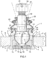
- Figure 1 shows an axial sectional view through a prior art ball joint 1 mounted by press fitting into an opening through an automotive component 2.
- the automotive component could be any that use ball joint connections of various configurations such as: a control arm; a stabilizer link; a stabilizer bar; and a steering linkage.
- a laterally radially extending flange 4 limits the axial installation of the housing 3 into the opening during press fitting when a seating surface 5 abuts the adjacent first side 6 of the automotive component 2.
- a removable retention spring clip 7 is provided adjacent the opposite second side 8 of the automotive component 2.
- the retention spring clip 7 can be a standard C-shaped snap ring clip or retaining ring removable with needle nosed pliers that are conventionally used.
- the retention spring clip 7 is radially biased inward and snaps into a peripheral retention groove 9 disposed in the exterior surface of the housing 3.
- the retention groove 9 is spaced axially from the seating surface 5 a predetermined distance that equals the thickness "t" of the automotive component 2 plus a gap "g".
- the gap "g” is generally provided to accommodate manufacturing tolerances and to provide clearance for the points of the snap ring pliers used in installation or removal that project into holes (not shown) in the ends of the C-shaped retention spring clip 7.
- the housing 3 encloses a ball stud 10 having a ball end 11 mounted within a lower spherical bearing 12.
- the upper portion of the ball end 11 bears against a spherical surface of the interior of the housing 3, however alternatively an upper bearing may be provided.
- the ball end 11 and bearing 12 are lubricated and held in the housing 3 by a roll formed edge 15 that is mechanically formed after the closure plate 16 and spring washer 17 are installed in the housing 3.
- Port 18 is fitted with a grease nipple (not shown) and lubricant is injected into the interior of the housing 3.
- the ball stud 10 has a shank 13 extending axially out of a crown 14 of the housing 3.
- a threaded end 19 of the ball stud 10 has a castle nut 20 and spring pin 21 to connect the ball stud 10 and automotive component 2 to other parts of the automotive suspension or steering system (not shown).
- a flexible boot 22 is secured in an upper groove 23 in the ball joint housing 3 using an outer spiral metal spring 24.
- the flexible boot 22 is installed by sliding the lower boot end over the crown 14 of the housing 3.
- the spiral metal spring 24 or other retention ring is radially stretched and placed on the exterior of the boot end outside the upper groove 23 to resiliently secure the boot end in the upper groove 23.
- a distal end 25 of the flexible boot 22 is sealingly engaged with seal lips (not shown) to slide on the ball stud shank 13 as the ball stud 10 pivots.
- the sealing of the flexible boot 22 with the spiral metal spring 24 in the groove 23, and with a sliding seal at the distal end 25, contains the lubricant within the interior of the housing 3 and within the interior of the flexible boot 22 and impedes contamination by abrasive particles, moisture and chemicals.
- Figures 2-8 illustrate an example embodiment of the invention relating to the housing, boot and automotive component shown without the ball stud, and bearing for simplicity.
- the embodiment uses a single peripheral groove 26 in the exterior of the ball joint housing 27 and a single metal base ring 28 embedded in the base end 29 of the flexible boot 30 to perform the dual tasks of (1) securing the flexible protective boot 30 to the ball joint housing 27 and (2) securing the press fit ball joint housing 27 in the through hole of an automotive component (31- Fig. 3 ) as a safety measure in the event that the press fit fails and the housing 27 is dislodged.
- Figure 2 is a side view of the ball joint housing 27 which in Fig. 3 is installed in a through opening 32 extending through the automotive component 31.
- the peripheral groove 26 is disposed above the adjacent surface 33 of the automotive component 31 to receive the flexible detents 34 (see Fig. 6 ) of the metal base ring 28.
- the base end 29 of the flexible boot 30 is installed over the crown 36 of the housing 27.
- the detents 34 resiliently bend and when pushed down further will snap lock into the peripheral groove 26 as indicated in Figure 8 .
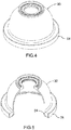
- Figures 4 and 5 show the flexible boot 30 with the metal base ring 28 embedded in the rubber of the boot 30 with inwardly directed detents 34.
- Figure 6 shows the base ring 28 alone showing the inward directed flexible metal detents 34 as sheet metal tabs.
- Figure 7 is an axial sectional detail through the base ring 28 and boot base end 29 showing the generally L shaped cross-section of the base ring 28 with inward directed flexible metal detents 34 or tabs and flexible seal lips 37 of the rubber boot 30 within which the base ring 28 is embedded.
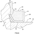
- Figure 8 shows the installed position of the base ring 28 and boot base 29 with the flexible metal detents 34 or tabs of the base ring 28 resiliently engaged in the peripheral groove 26 of the housing 27. The resilient rubber seal lips 37 are fully compressed against the housing 27 and the adjacent surface 33 of the automotive component 31.
- the invention provides a ball joint housing 27 for mounting into an opening 32 through an automotive component 33.
- a flexible protective boot 30 seals against the shank (not shown) of a ball stud (not shown) with a ball end (not shown) mounted within the housing 27.
- the shank extends axially upward out of a crown 36 of the housing 27.
- the housing 27 has an exterior substantially cylindrical surface that is press fit into the opening 32 from bottom to top as drawn. When fully press fit in place, a flange 38 radially extending from the exterior surface of the housing 27 has a seating surface 39 abutting an adjacent first side 40 of the automotive component 31.
- the peripheral groove 26 in the exterior surface of the housing 27 is spaced axially from the seating surface 39 a predetermined distance "x" as shown in Figure 2 . Distance "x" is at least the thickness of the automotive component 31, and may include a tolerance for manufacturing and to allow the detents 34 to engage the groove 26.
- the peripheral groove 26 has a radially extending detent surface 41 recessed radially inwardly by a dimension "z".
- the peripheral groove 26 has a tapered surface 42 extending from the radially inward edge of the detent surface 41 to the exterior cylindrical surface of the housing 27 a distance of "y".
- Other shapes of grooves 26 can be used.
- a tapered surface 42 provides the required detent surface 41 and a surface against which to seal the lips 37 ( Fig. 8 ) without unnecessarily removing material from the wall of the housing 27.
- the base end 29 includes a metal base ring 28 with inwardly extending flexible detents 34 engaged in the peripheral groove 26 when installed.
- the base end 29 of the rubber flexible boot 30 has flexible rubber lips 37 that form a base seal sealing engaged on the exterior surface of the housing 27.
- the base ring 28 is generally L-shaped having a radially extending abutment surface 43 for retaining an adjacent second side 44 of the automotive component 31.
- the base ring 28 best seen in Figures 6-8 also can have an annular exterior wall 45 extending from an outer periphery of the abutment surface 43.
- the base ring 28 can be vulcanized with the rubber boot 30 when the boot 30 is molded.
- the base ring 28 illustrated is stamped from sheet metal and the detent 34 comprises multiple radially extending resilient tabs.
- the detent tabs 34 extend from an inner periphery of the abutment surface 43 in an inclined axial and radial inward direction toward the crown 36 of the housing 27.
- the crown 36 of the housing 27 in the example is shown with a rounded edge but a tapered edge would serve equally to guide the detents 34.
- the crown outer diameter is less than the at rest inner detent diameter so that the detents 34 are gradually flexed on contact with the crown 36 and then resiliently engage the detent surface 41 of the groove 26 when the abutment surface 43 of the base ring 28 is fully engaged with the second side 44 of the automotive component 31.
- the base end 29 of the flexible boot 30 includes a laterally extending installation flange 46 of flexible material joined to the metal base ring 28 opposite the abutment surface 43.
- an annular tubular installation tool 35 may be used to hold the base end 29 and metal base ring 28.
- the annular contact end of the tool 35 is shaped to engage with the laterally extending installation flange 46 of the boot 30.
- the metal base ring 28 may also include an annular exterior wall 45 that engages in the tool 35 and transfers impact loads to the base ring 28 from the tool 35 .
- the tool 35 can be simply struck with a rubber mallet on an impact end (not shown) opposite the annular contact end engaging the metal base ring 28 to force the boot 30 in the direction of arrows shown in Figure 3 .
- the present invention uses a single metal base ring 28 to perform two functions, namely to retain the flexible boot 30 on the housing 27 and provide a secondary retention to retain the housing 27 in the automotive component 31 in the event that the primary retention means fails, namely the press fit between the ball joint housing and the automotive component.
- the size of the housing 27 can be reduced axially compared to the prior art since a single retention groove 26 in the exterior surface of the housing 27 is required to engage a single base ring 28 and detents 34. Installation is simplified since only one part is handled and used.
- a more durable, protected, superior seal against contaminants is provided for the base end 29 of the flexible boot 27 which fits tightly against the adjacent surface 44 of the automotive component 31 and against the tapered surface 42 of the housing 27.
- the housing 27 is secured tightly to the automotive component 31 without a gap between the retention device (metal base ring 28) and the automotive component 31.
Abstract
Description
- The invention relates to a locking boot for a flexible protective boot of a ball joint, used in an automotive suspension system, steering system or the like, having the dual purposes of retaining the boot securely sealed to the ball joint housing and also axially retaining the ball joint housing in an mating automotive component.
- Ball joints allow pivoting movement of automotive suspension or steering components relative to each other while retaining the capacity to transmit axial and shear forces thereby accommodating wheel movement, steering movement, stability and wheel alignment. Ball joints include a stud with a shank that is typically threaded at one end for releasably connecting to an adjacent component. Other types of connections between the stud and component are also used. The stud has a spherical ball at the opposite end mounted within spherical bearings housed in a ball joint housing. Wear between the ball end and bearings is reduced by use of fluid lubricants.
- A flexible rubber boot is resiliently sealed with a sliding seal to the outer surface of the stud shank and a base of the flexible boot is sealed and secured to the outer surface of the housing, to prevent contamination of the lubricant and contact surfaces by abrasive particles, moisture or chemicals like salt, and the accompanying abrasive wear, lubricant degradation and metal corrosion. The protective rubber boot holds the lubricant within the boot interior and the boot seals prevent contaminants from contacting the moving parts and lubricant within. Common means of mounting the base of a "press-in" flexible boot to the housing is to press, stretch and slide the boot base over the exterior of the rigid cylindrical housing. A press-in boot base is conventionally secured using a recessed groove in the housing, a spiral ring clip contracting the exterior of flexible boot around the exterior of the boot base, a resilient metal ring clip embedded in the rubber boot base, or a combination of these elements.
- Such flexible boots can be easily removed since the retaining ring clips remain flexible and during heavy use the seal between the base of the boot and the housing can be damaged or unintentionally loosened thereby allowing penetration of contaminants into the lubricant and into contact with the bearings, ball end and other interior parts of the ball joint. Once contaminants such as abrasive particles, salt, moisture or chemicals are present within the interior of the ball joint, wear and corrosion are accelerated and the useful service life of the ball joint is reduced significantly.
- Ball joints are mounted to adjacent automotive suspension, stabilization and steering components by mechanical press fitting or threading the cylindrical housing of the ball joint into a matching through hole in the component. For example ball joints are mounted to upper and lower control arms in wheel suspension systems, mounted at both ends of a stabilizer link, mounted to stabilizer bars and mounted in steering linkages.
- A through hole is cast or forged, reamed, drilled or machined into the automotive component to match the exterior cylindrical surface of the ball joint housing. The housing often includes a laterally extending flange to abut the surface on the side of the component through which the ball joint is inserted. Once the housing is press fit or threaded and securely seated with the flange against the component surface, a resilient retention ring clip is mounted into a matching groove in the exterior of the housing.
- The retention ring clip together with the flange secures the housing on opposite sides of the automotive component to limit relative axial movement. In the event that the press fit or threading connection fails, the retention ring clip provides a safety back-up system to prevent the ball joint and component from separating axially. Catastrophic failure and loss of vehicle control could occur if the ball joint housing becomes axially dislodged from the automotive component, particularly critical steering or suspension components.
- The retention ring clip is often spaced an axial distance from the adjacent surface of the automotive component to allow access with tools and aid in installation. When dislodgement occurs, the axial distance between the retention ring clip and automotive component causes significant rattling noise, fretting and impact damage that further reduces the useful service life of the ball joint. A tight engagement between the retention ring clip and component surface would interfere with inserting the points of locking snap-ring pliers or other tools into matching holes in the ends of C-shaped retention ring clips during installation and manufacture.
- Therefore some degree of gap is provided for tool access despite the possibility of rattling when the housing is dislodged, since the retention ring clip may be considered to be an emergency or seldom required back up safety measure to prevent catastrophic failure. Any rattling may be considered to be an audible warning that something is out of place or damaged in the suspension or steering system which requires investigation by a mechanic before a major failure occurs.
- It is desirable to provide an improved connection between the ball joint housing and the automotive component, an improved connection between the ball joint housing and the flexible protective boot, and to simplify manufacture, installation and maintenance of auto motive ball joints.
- Features that distinguish the present invention from the background art will be apparent from review of the disclosure, drawings and description of the invention presented below.
- The invention provides a ball joint and an assembled automotive component having an opening through which a ball joint extends, the ball joint comprising: a housing having an exterior substantially cylindrical surface, a seating surface radially extending from the exterior surface for abutting an adjacent first side of the automotive component, and a peripheral groove disposed in the exterior surface spaced axially from the seating surface a predetermined distance; a ball stud having a ball end mounted within the housing and a shank extending axially out of a crown of the housing; a flexible boot having an distal end sealingly engaged on the shank and an opposing proximal base end, the base end including a metal base ring with an inwardly extending flexible detent engaged in the peripheral groove in the housing and a base seal sealing engaged on the exterior surface, the base ring having a radially extending abutment surface for retaining an adjacent second side of the automotive component, and wherein the automotive component is selected from the group consisting of: a control arm; a stabilizer link; a stabilizer bar; and a steering linkage.
- Prior art ball joints as described above use two pieces of hardware to perform the tasks of (1) securing the base of the flexible protective boot to the ball joint housing and (2) securing the press fit ball joint housing in the through hole of an automotive component as a safety measure in the event that the press fit fails and the housing is dislodged. In contrast, the present invention uses a single piece of hardware to perform both functions, namely the metal base ring with an inwardly flexible detent located at the base end of the flexible boot as described below.
- In order that the invention may be readily understood, one embodiment of the invention is illustrated by way of example in the accompanying drawings.
-
Figure 1 is an axial sectional view through a prior art ball joint having a flexible boot secured in an upper groove in the ball joint housing using an outer spiral metal spring and having a retention spring clip in a lower groove that together with the lower flange abut both sides of the automotive component through which the ball joint housing extends. -
Figure 2 is a side view of a ball joint housing in accordance with an embodiment of the invention that is adapted to receive an upper and a lower bearing, having a lower flange and a single upper groove. -
Figure 3 is a side view of the ball joint inFig. 2 shown installed in a through opening extending through an automotive component where the groove is disposed above the adjacent surface of the automotive component to receive the detents of the metal base ring slidingly installed using an annular installation tool. -
Figure 4 is a top side isometric view of a flexible boot having a metal base ring embedded in the rubber of the boot. -
Figure 5 is a cutaway top side isometric view likeFig. 4 with an axial section through the flexible boot and base ring showing the generally L shaped cross-section with inward directed flexible metal tabs and resilient rubber sealing lips. -
Figure 6 is a top side isometric view of the base ring alone showing inward directed flexible metal detent tabs. -
Figure 7 is an axial sectional detail through the base ring and boot base as inFig. 5 showing the generally L shaped cross-section of the metal base ring with inward directed flexible metal detent tabs and flexible seal lips of the rubber boot within which the metal base ring is embedded. -
Figure 8 is an axial sectional detail through the base ring and boot base as inFig. 7 with the flexible metal tabs of the base ring resiliently engaged in the groove of the housing and seal lips compressed against the housing. - Further details of the invention and its advantages will be apparent from the detailed description included below.
-
Figure 1 shows an axial sectional view through a prior art ball joint 1 mounted by press fitting into an opening through anautomotive component 2. The automotive component could be any that use ball joint connections of various configurations such as: a control arm; a stabilizer link; a stabilizer bar; and a steering linkage. A laterally radially extendingflange 4 limits the axial installation of thehousing 3 into the opening during press fitting when aseating surface 5 abuts the adjacentfirst side 6 of theautomotive component 2. - To retain the
housing 3 in thecomponent 2 if the press fit connection fails, a removableretention spring clip 7 is provided adjacent the oppositesecond side 8 of theautomotive component 2. Theretention spring clip 7 can be a standard C-shaped snap ring clip or retaining ring removable with needle nosed pliers that are conventionally used. Theretention spring clip 7 is radially biased inward and snaps into aperipheral retention groove 9 disposed in the exterior surface of thehousing 3. Theretention groove 9 is spaced axially from the seating surface 5 a predetermined distance that equals the thickness "t" of theautomotive component 2 plus a gap "g". The gap "g" is generally provided to accommodate manufacturing tolerances and to provide clearance for the points of the snap ring pliers used in installation or removal that project into holes (not shown) in the ends of the C-shapedretention spring clip 7. - The
housing 3 encloses aball stud 10 having aball end 11 mounted within a lowerspherical bearing 12. In the example shown the upper portion of theball end 11 bears against a spherical surface of the interior of thehousing 3, however alternatively an upper bearing may be provided. Theball end 11 andbearing 12 are lubricated and held in thehousing 3 by a roll formededge 15 that is mechanically formed after theclosure plate 16 andspring washer 17 are installed in thehousing 3.Port 18 is fitted with a grease nipple (not shown) and lubricant is injected into the interior of thehousing 3. - The
ball stud 10 has ashank 13 extending axially out of acrown 14 of thehousing 3. A threadedend 19 of theball stud 10 has acastle nut 20 andspring pin 21 to connect theball stud 10 andautomotive component 2 to other parts of the automotive suspension or steering system (not shown). - In the prior art example of
Figure 1 , aflexible boot 22 is secured in anupper groove 23 in theball joint housing 3 using an outerspiral metal spring 24. Theflexible boot 22 is installed by sliding the lower boot end over thecrown 14 of thehousing 3. Thespiral metal spring 24 or other retention ring is radially stretched and placed on the exterior of the boot end outside theupper groove 23 to resiliently secure the boot end in theupper groove 23. Adistal end 25 of theflexible boot 22 is sealingly engaged with seal lips (not shown) to slide on theball stud shank 13 as theball stud 10 pivots. The sealing of theflexible boot 22 with thespiral metal spring 24 in thegroove 23, and with a sliding seal at thedistal end 25, contains the lubricant within the interior of thehousing 3 and within the interior of theflexible boot 22 and impedes contamination by abrasive particles, moisture and chemicals. -
Figures 2-8 illustrate an example embodiment of the invention relating to the housing, boot and automotive component shown without the ball stud, and bearing for simplicity. The embodiment uses a singleperipheral groove 26 in the exterior of the balljoint housing 27 and a singlemetal base ring 28 embedded in thebase end 29 of theflexible boot 30 to perform the dual tasks of (1) securing the flexibleprotective boot 30 to the balljoint housing 27 and (2) securing the press fit balljoint housing 27 in the through hole of an automotive component (31-Fig. 3 ) as a safety measure in the event that the press fit fails and thehousing 27 is dislodged. -
Figure 2 is a side view of the balljoint housing 27 which inFig. 3 is installed in a throughopening 32 extending through theautomotive component 31. Theperipheral groove 26 is disposed above theadjacent surface 33 of theautomotive component 31 to receive the flexible detents 34 (seeFig. 6 ) of themetal base ring 28. As shown inFigure 3 , using anannular installation tool 35 and pressing in the direction of the arrows, thebase end 29 of theflexible boot 30 is installed over thecrown 36 of thehousing 27. Thedetents 34 resiliently bend and when pushed down further will snap lock into theperipheral groove 26 as indicated inFigure 8 . -
Figures 4 and 5 show theflexible boot 30 with themetal base ring 28 embedded in the rubber of theboot 30 with inwardly directeddetents 34.Figure 6 shows thebase ring 28 alone showing the inward directedflexible metal detents 34 as sheet metal tabs.Figure 7 is an axial sectional detail through thebase ring 28 and bootbase end 29 showing the generally L shaped cross-section of thebase ring 28 with inward directedflexible metal detents 34 or tabs andflexible seal lips 37 of therubber boot 30 within which thebase ring 28 is embedded.Figure 8 shows the installed position of thebase ring 28 andboot base 29 with theflexible metal detents 34 or tabs of thebase ring 28 resiliently engaged in theperipheral groove 26 of thehousing 27. The resilientrubber seal lips 37 are fully compressed against thehousing 27 and theadjacent surface 33 of theautomotive component 31. - Referring to
Figures 2-3 , the invention provides a balljoint housing 27 for mounting into anopening 32 through anautomotive component 33. A flexibleprotective boot 30 seals against the shank (not shown) of a ball stud (not shown) with a ball end (not shown) mounted within thehousing 27. The shank extends axially upward out of acrown 36 of thehousing 27. - The
housing 27 has an exterior substantially cylindrical surface that is press fit into the opening 32 from bottom to top as drawn. When fully press fit in place, aflange 38 radially extending from the exterior surface of thehousing 27 has aseating surface 39 abutting an adjacentfirst side 40 of theautomotive component 31. Theperipheral groove 26 in the exterior surface of thehousing 27 is spaced axially from the seating surface 39 a predetermined distance "x" as shown inFigure 2 . Distance "x" is at least the thickness of theautomotive component 31, and may include a tolerance for manufacturing and to allow thedetents 34 to engage thegroove 26. Theperipheral groove 26 has a radially extendingdetent surface 41 recessed radially inwardly by a dimension "z". As shown in the example, theperipheral groove 26 has a taperedsurface 42 extending from the radially inward edge of thedetent surface 41 to the exterior cylindrical surface of the housing 27 a distance of "y". Other shapes ofgrooves 26 can be used. A taperedsurface 42 provides the requireddetent surface 41 and a surface against which to seal the lips 37 (Fig. 8 ) without unnecessarily removing material from the wall of thehousing 27. - Referring to
Figure 3-8 , thebase end 29 includes ametal base ring 28 with inwardly extendingflexible detents 34 engaged in theperipheral groove 26 when installed. As best seen inFigures 7-8 Thebase end 29 of the rubberflexible boot 30 hasflexible rubber lips 37 that form a base seal sealing engaged on the exterior surface of thehousing 27. Thebase ring 28 is generally L-shaped having a radially extendingabutment surface 43 for retaining an adjacentsecond side 44 of theautomotive component 31. - The
base ring 28 best seen inFigures 6-8 also can have anannular exterior wall 45 extending from an outer periphery of theabutment surface 43. Thebase ring 28 can be vulcanized with therubber boot 30 when theboot 30 is molded. Thebase ring 28 illustrated is stamped from sheet metal and thedetent 34 comprises multiple radially extending resilient tabs. Thedetent tabs 34 extend from an inner periphery of theabutment surface 43 in an inclined axial and radial inward direction toward thecrown 36 of thehousing 27. Thecrown 36 of thehousing 27 in the example is shown with a rounded edge but a tapered edge would serve equally to guide thedetents 34. The crown outer diameter is less than the at rest inner detent diameter so that thedetents 34 are gradually flexed on contact with thecrown 36 and then resiliently engage thedetent surface 41 of thegroove 26 when theabutment surface 43 of thebase ring 28 is fully engaged with thesecond side 44 of theautomotive component 31. - The
base end 29 of theflexible boot 30 includes a laterally extendinginstallation flange 46 of flexible material joined to themetal base ring 28 opposite theabutment surface 43. As indicated inFigure 3 an annulartubular installation tool 35 may be used to hold thebase end 29 andmetal base ring 28. The annular contact end of thetool 35 is shaped to engage with the laterally extendinginstallation flange 46 of theboot 30. Themetal base ring 28 may also include anannular exterior wall 45 that engages in thetool 35 and transfers impact loads to thebase ring 28 from thetool 35 . Thetool 35 can be simply struck with a rubber mallet on an impact end (not shown) opposite the annular contact end engaging themetal base ring 28 to force theboot 30 in the direction of arrows shown inFigure 3 . - The present invention uses a single
metal base ring 28 to perform two functions, namely to retain theflexible boot 30 on thehousing 27 and provide a secondary retention to retain thehousing 27 in theautomotive component 31 in the event that the primary retention means fails, namely the press fit between the ball joint housing and the automotive component. The size of thehousing 27 can be reduced axially compared to the prior art since asingle retention groove 26 in the exterior surface of thehousing 27 is required to engage asingle base ring 28 anddetents 34. Installation is simplified since only one part is handled and used. A more durable, protected, superior seal against contaminants is provided for thebase end 29 of theflexible boot 27 which fits tightly against theadjacent surface 44 of theautomotive component 31 and against the taperedsurface 42 of thehousing 27. Thehousing 27 is secured tightly to theautomotive component 31 without a gap between the retention device (metal base ring 28) and theautomotive component 31. - Although the above description relates to a specific preferred embodiment as presently contemplated by the inventors, it will be understood that the invention in its broad aspect includes mechanical and functional equivalents of the elements described herein.
Claims (10)
- A ball joint, for mounting into an opening through an automotive component, the ball joint comprising:a housing having an exterior substantially cylindrical surface, a seating surface radially extending from the exterior surface for abutting an adjacent first side of the automotive component, and a peripheral groove disposed in the exterior surface spaced axially from the seating surface a predetermined distance;a ball stud having a ball end mounted within the housing and a shank extending axially out of a crown of the housing;a flexible boot having an distal end sealingly engaged on the shank and an opposing proximal base end, the base end including a metal base ring with an inwardly extending flexible detent engaged in the peripheral groove in the housing and a base seal sealing engaged on the exterior surface, the base ring having a radially extending abutment surface for retaining an adjacent second side of the automotive component.
- The ball joint according to claim 1, wherein the base ring has an annular exterior wall extending from an outer periphery of the abutment surface.
- The ball joint according to claim 2, wherein the base ring is formed of sheet metal and the detent comprises radially extending resilient tabs.
- The ball joint according to claim 3, wherein the tabs extend from an inner periphery of the abutment surface in an axial direction toward the crown of the housing.
- The ball joint according to claim 1 wherein the peripheral groove in the housing has a radially extending detent surface.
- The ball joint according to claim 5 wherein the peripheral groove in the housing has a tapered surface extending from a radially inward edge of the detent surface to the exterior substantially cylindrical surface of the housing.
- The ball joint according to claim 1 wherein the crown of the housing has a distal crown diameter less than an at rest inner detent diameter.
- The ball joint according to claim 1 wherein the base end of the flexible boot includes a laterally extending installation flange of flexible material joined to the metal base ring opposite the abutment surface.
- The ball joint according to claim 8 comprising a tubular installation tool having an annular contact end engageable with the laterally extending installation flange of the flexible boot and an impact end opposite the annular contact end.
- An automotive component having an opening through which a ball joint extends, the ball joint comprising:a housing having an exterior substantially cylindrical surface, a seating surface radially extending from the exterior surface for abutting an adjacent first side of the automotive component, and a peripheral groove disposed in the exterior surface spaced axially from the seating surface a predetermined distance;a ball stud having a ball end mounted within the housing and a shank extending axially out of a crown of the housing;a flexible boot having an distal end sealingly engaged on the shank and an opposing proximal base end, the base end including a metal base ring with an inwardly extending flexible detent engaged in the peripheral groove in the housing and a base seal sealing engaged on the exterior surface, the base ring having a radially extending abutment surface for retaining an adjacent second side of the automotive component, andwherein the automotive component is selected from the group consisting of: a control arm; a stabilizer link; a stabilizer bar; and a steering linkage.
Applications Claiming Priority (1)
| Application Number | Priority Date | Filing Date | Title |
|---|---|---|---|
| US15/338,933 US9771971B1 (en) | 2016-10-31 | 2016-10-31 | Locking boot for ball joint |
Publications (3)
| Publication Number | Publication Date |
|---|---|
| EP3330555A2 true EP3330555A2 (en) | 2018-06-06 |
| EP3330555A3 EP3330555A3 (en) | 2018-06-20 |
| EP3330555B1 EP3330555B1 (en) | 2019-04-24 |
Family
ID=59775509
Family Applications (1)
| Application Number | Title | Priority Date | Filing Date |
|---|---|---|---|
| EP17020479.6A Active EP3330555B1 (en) | 2016-10-31 | 2017-10-18 | Locking boot for ball joint |
Country Status (5)
| Country | Link |
|---|---|
| US (1) | US9771971B1 (en) |
| EP (1) | EP3330555B1 (en) |
| CN (1) | CN108019419B (en) |
| CA (1) | CA2967428C (en) |
| MX (1) | MX369569B (en) |
Families Citing this family (6)
| Publication number | Priority date | Publication date | Assignee | Title |
|---|---|---|---|---|
| US10359071B2 (en) * | 2016-11-16 | 2019-07-23 | Federal-Mogul Motorparts Llc | Socket assembly and method of making |
| USD839796S1 (en) * | 2017-03-07 | 2019-02-05 | Nan-Chang Chiu | Bearer container for a multi-axis aircraft |
| US11466727B2 (en) * | 2019-09-10 | 2022-10-11 | Federal-Mogul Motorparts Llc | Ball socket assembly, dust boot therefor and method of construction thereof |
| CN111536244A (en) * | 2020-04-08 | 2020-08-14 | 上海机电工程研究所 | Staggered rain-proof structure suitable for rotating shaft |
| CN111873732B (en) * | 2020-07-14 | 2021-09-17 | 中车大同电力机车有限公司 | Macpherson type independent suspension device and vehicle |
| CN116792399B (en) * | 2023-06-19 | 2024-01-23 | 玉环津力汽车配件有限公司 | Steering pull rod ball head structure and steering pull rod assembly |
Family Cites Families (30)
| Publication number | Priority date | Publication date | Assignee | Title |
|---|---|---|---|---|
| US2786359A (en) | 1955-01-14 | 1957-03-26 | Panseal Inc | Waterproof panel seal nut |
| GB1005682A (en) * | 1963-04-23 | 1965-09-29 | Automotive Prod Co Ltd | Improvements in and relating to sealing boots for joint assemblies |
| US3322445A (en) | 1964-10-13 | 1967-05-30 | Chrysler Corp | Ball joint seal |
| US3310326A (en) | 1964-11-19 | 1967-03-21 | Illinois Tool Works | Retainer |
| JPS523068B2 (en) * | 1973-09-25 | 1977-01-26 | ||
| JPS5349658A (en) | 1976-10-15 | 1978-05-06 | Nippon Oil Seal Ind Co Ltd | Ball joint seal |
| US4322175A (en) | 1980-05-12 | 1982-03-30 | Trw Inc. | Joint assembly |
| DE3339874C1 (en) * | 1983-11-04 | 1985-06-13 | TRW Ehrenreich GmbH & Co KG, 4000 Düsseldorf | Attachment of a sealing bellows to the joint housing of a ball joint |
| DE3741347C1 (en) * | 1987-12-07 | 1989-05-11 | Trw Ehrenreich Gmbh | Fastening and method for fastening a sealing bellows to the joint housing of a ball joint |
| DE3930741C1 (en) * | 1989-09-14 | 1990-12-13 | Lemfoerder Metallwaren Ag, 2844 Lemfoerde, De | |
| US5380114A (en) * | 1993-01-25 | 1995-01-10 | Trw Inc. | Ball joint assembly and method of mounting |
| DE69413186T2 (en) * | 1993-12-17 | 1999-04-15 | Chrysler Corp | Ball joint |
| US5466084A (en) | 1994-06-16 | 1995-11-14 | Dana Corporation | Dust boot retainer ring |
| JP2865273B2 (en) * | 1994-06-20 | 1999-03-08 | 武蔵精密工業株式会社 | Ball joint |
| JP3090588B2 (en) * | 1995-05-12 | 2000-09-25 | 株式会社ソミック石川 | Ball joint |
| US5876149A (en) * | 1995-06-29 | 1999-03-02 | Trw Fahrwerksysteme Gmbh & Co. Kg | Ball joint |
| DE19542071C2 (en) * | 1995-11-11 | 2000-03-30 | Trw Fahrwerksyst Gmbh & Co | Ball joint |
| US5697723A (en) * | 1995-12-12 | 1997-12-16 | Trw Inc. | Joint assembly |
| DE19952427A1 (en) * | 1999-10-30 | 2001-05-03 | Audi Ag | Ball joint |
| BR0006515B1 (en) * | 2000-12-18 | 2009-01-13 | Spherical hinged seal cap fastening ring. | |
| US6439795B1 (en) | 2000-12-20 | 2002-08-27 | Federal-Mogul Technology Limited | Ball joint cover |
| US6773197B2 (en) * | 2002-10-09 | 2004-08-10 | Trw Inc. | Ball joint |
| US7237978B2 (en) * | 2004-07-22 | 2007-07-03 | ZF Lemförder Metallwaren AG | Joint sealing bellows with sealing ring and assembly/installation method |
| DE102005006884B4 (en) | 2005-02-15 | 2019-01-10 | THK RHYTHM AUTOMOTIVE GmbH | ball joint |
| US7670078B2 (en) * | 2005-08-25 | 2010-03-02 | James Elterman | Dust boot with grease relief passage |
| JP4873122B2 (en) | 2005-11-21 | 2012-02-08 | Nok株式会社 | Dust cover |
| US7980564B2 (en) | 2006-10-13 | 2011-07-19 | Nok Corporation | Metal fixture for dust cover |
| US9476447B2 (en) * | 2008-05-21 | 2016-10-25 | Federal-Mogul Powertrain, Inc. | Ball joint assembly and method of making |
| JP6376426B2 (en) * | 2012-11-28 | 2018-08-22 | 株式会社ソミック石川 | Ball joint |
| CN204187015U (en) * | 2014-10-27 | 2015-03-04 | 四川望锦机械有限公司 | Automobile ball pivot two-way enhancing sealing and dustproof cover |
-
2016
- 2016-10-31 US US15/338,933 patent/US9771971B1/en active Active
-
2017
- 2017-05-12 CA CA2967428A patent/CA2967428C/en active Active
- 2017-06-08 CN CN201710429962.2A patent/CN108019419B/en active Active
- 2017-10-18 EP EP17020479.6A patent/EP3330555B1/en active Active
- 2017-10-30 MX MX2017013938A patent/MX369569B/en active IP Right Grant
Also Published As
| Publication number | Publication date |
|---|---|
| CN108019419B (en) | 2020-02-21 |
| MX2017013938A (en) | 2018-09-28 |
| EP3330555B1 (en) | 2019-04-24 |
| CA2967428C (en) | 2018-06-05 |
| MX369569B (en) | 2019-11-12 |
| CN108019419A (en) | 2018-05-11 |
| US9771971B1 (en) | 2017-09-26 |
| CA2967428A1 (en) | 2017-09-06 |
| EP3330555A3 (en) | 2018-06-20 |
Similar Documents
| Publication | Publication Date | Title |
|---|---|---|
| CA2967428C (en) | Locking boot for ball joint | |
| US5374089A (en) | High pressure quick connector | |
| US10473146B2 (en) | Ball socket assembly | |
| US9145990B2 (en) | Fluid coupling | |
| CN109312775B (en) | Socket assembly and method of manufacturing socket assembly | |
| EP2392477A2 (en) | Spindle nut | |
| EP3542077B1 (en) | Improved socket assembly and method of making | |
| EP3592999B1 (en) | Ball joint assembly | |
| KR20170033315A (en) | Dust boot for a moveable joint | |
| US11441597B2 (en) | Socket assembly with a pressed cover plate and method of construction thereof | |
| EP3433503B1 (en) | Boot for a socket assembly | |
| US5078533A (en) | Driveline yoke with improved seal retainer | |
| US6371682B1 (en) | Anchor post non-articulating idler socket joint | |
| EP3453593B1 (en) | Kingpin assembly with a torque receiving configuration | |
| CN111065830B (en) | Improved socket assembly and method of manufacture | |
| JP4514937B2 (en) | Ball joint | |
| US9982819B2 (en) | Tube seal assembly | |
| US10954995B2 (en) | Socket assembly and method of making | |
| US10473149B2 (en) | Pivot joint assembly for vehicle steering and suspension systems | |
| JP2021001626A (en) | Separation prevention structure of pipe connection portion | |
| US6076815A (en) | Sealing device for spring suspension | |
| US20060175831A1 (en) | Fluid quick connect contamination cover | |
| CN115711329A (en) | Pipe joint and method of mounting the same |
Legal Events
| Date | Code | Title | Description |
|---|---|---|---|
| PUAI | Public reference made under article 153(3) epc to a published international application that has entered the european phase |
Free format text: ORIGINAL CODE: 0009012 |
|
| STAA | Information on the status of an ep patent application or granted ep patent |
Free format text: STATUS: THE APPLICATION HAS BEEN PUBLISHED |
|
| PUAL | Search report despatched |
Free format text: ORIGINAL CODE: 0009013 |
|
| AK | Designated contracting states |
Kind code of ref document: A2 Designated state(s): AL AT BE BG CH CY CZ DE DK EE ES FI FR GB GR HR HU IE IS IT LI LT LU LV MC MK MT NL NO PL PT RO RS SE SI SK SM TR |
|
| AX | Request for extension of the european patent |
Extension state: BA ME |
|
| AK | Designated contracting states |
Kind code of ref document: A3 Designated state(s): AL AT BE BG CH CY CZ DE DK EE ES FI FR GB GR HR HU IE IS IT LI LT LU LV MC MK MT NL NO PL PT RO RS SE SI SK SM TR |
|
| AX | Request for extension of the european patent |
Extension state: BA ME |
|
| RIC1 | Information provided on ipc code assigned before grant |
Ipc: B60G 7/00 20060101ALI20180515BHEP Ipc: F16J 3/04 20060101ALI20180515BHEP Ipc: B62D 7/16 20060101ALI20180515BHEP Ipc: F16C 11/06 20060101AFI20180515BHEP |
|
| STAA | Information on the status of an ep patent application or granted ep patent |
Free format text: STATUS: REQUEST FOR EXAMINATION WAS MADE |
|
| 17P | Request for examination filed |
Effective date: 20181113 |
|
| RBV | Designated contracting states (corrected) |
Designated state(s): AL AT BE BG CH CY CZ DE DK EE ES FI FR GB GR HR HU IE IS IT LI LT LU LV MC MK MT NL NO PL PT RO RS SE SI SK SM TR |
|
| GRAP | Despatch of communication of intention to grant a patent |
Free format text: ORIGINAL CODE: EPIDOSNIGR1 |
|
| STAA | Information on the status of an ep patent application or granted ep patent |
Free format text: STATUS: GRANT OF PATENT IS INTENDED |
|
| INTG | Intention to grant announced |
Effective date: 20190214 |
|
| GRAS | Grant fee paid |
Free format text: ORIGINAL CODE: EPIDOSNIGR3 |
|
| GRAA | (expected) grant |
Free format text: ORIGINAL CODE: 0009210 |
|
| STAA | Information on the status of an ep patent application or granted ep patent |
Free format text: STATUS: THE PATENT HAS BEEN GRANTED |
|
| AK | Designated contracting states |
Kind code of ref document: B1 Designated state(s): AL AT BE BG CH CY CZ DE DK EE ES FI FR GB GR HR HU IE IS IT LI LT LU LV MC MK MT NL NO PL PT RO RS SE SI SK SM TR |
|
| REG | Reference to a national code |
Ref country code: GB Ref legal event code: FG4D |
|
| REG | Reference to a national code |
Ref country code: CH Ref legal event code: EP |
|
| REG | Reference to a national code |
Ref country code: AT Ref legal event code: REF Ref document number: 1124491 Country of ref document: AT Kind code of ref document: T Effective date: 20190515 Ref country code: IE Ref legal event code: FG4D |
|
| REG | Reference to a national code |
Ref country code: DE Ref legal event code: R096 Ref document number: 602017003393 Country of ref document: DE |
|
| REG | Reference to a national code |
Ref country code: NL Ref legal event code: MP Effective date: 20190424 |
|
| REG | Reference to a national code |
Ref country code: LT Ref legal event code: MG4D |
|
| PG25 | Lapsed in a contracting state [announced via postgrant information from national office to epo] |
Ref country code: NL Free format text: LAPSE BECAUSE OF FAILURE TO SUBMIT A TRANSLATION OF THE DESCRIPTION OR TO PAY THE FEE WITHIN THE PRESCRIBED TIME-LIMIT Effective date: 20190424 |
|
| PG25 | Lapsed in a contracting state [announced via postgrant information from national office to epo] |
Ref country code: ES Free format text: LAPSE BECAUSE OF FAILURE TO SUBMIT A TRANSLATION OF THE DESCRIPTION OR TO PAY THE FEE WITHIN THE PRESCRIBED TIME-LIMIT Effective date: 20190424 Ref country code: LT Free format text: LAPSE BECAUSE OF FAILURE TO SUBMIT A TRANSLATION OF THE DESCRIPTION OR TO PAY THE FEE WITHIN THE PRESCRIBED TIME-LIMIT Effective date: 20190424 Ref country code: FI Free format text: LAPSE BECAUSE OF FAILURE TO SUBMIT A TRANSLATION OF THE DESCRIPTION OR TO PAY THE FEE WITHIN THE PRESCRIBED TIME-LIMIT Effective date: 20190424 Ref country code: HR Free format text: LAPSE BECAUSE OF FAILURE TO SUBMIT A TRANSLATION OF THE DESCRIPTION OR TO PAY THE FEE WITHIN THE PRESCRIBED TIME-LIMIT Effective date: 20190424 Ref country code: PT Free format text: LAPSE BECAUSE OF FAILURE TO SUBMIT A TRANSLATION OF THE DESCRIPTION OR TO PAY THE FEE WITHIN THE PRESCRIBED TIME-LIMIT Effective date: 20190824 Ref country code: NO Free format text: LAPSE BECAUSE OF FAILURE TO SUBMIT A TRANSLATION OF THE DESCRIPTION OR TO PAY THE FEE WITHIN THE PRESCRIBED TIME-LIMIT Effective date: 20190724 Ref country code: AL Free format text: LAPSE BECAUSE OF FAILURE TO SUBMIT A TRANSLATION OF THE DESCRIPTION OR TO PAY THE FEE WITHIN THE PRESCRIBED TIME-LIMIT Effective date: 20190424 Ref country code: SE Free format text: LAPSE BECAUSE OF FAILURE TO SUBMIT A TRANSLATION OF THE DESCRIPTION OR TO PAY THE FEE WITHIN THE PRESCRIBED TIME-LIMIT Effective date: 20190424 |
|
| PG25 | Lapsed in a contracting state [announced via postgrant information from national office to epo] |
Ref country code: GR Free format text: LAPSE BECAUSE OF FAILURE TO SUBMIT A TRANSLATION OF THE DESCRIPTION OR TO PAY THE FEE WITHIN THE PRESCRIBED TIME-LIMIT Effective date: 20190725 Ref country code: LV Free format text: LAPSE BECAUSE OF FAILURE TO SUBMIT A TRANSLATION OF THE DESCRIPTION OR TO PAY THE FEE WITHIN THE PRESCRIBED TIME-LIMIT Effective date: 20190424 Ref country code: PL Free format text: LAPSE BECAUSE OF FAILURE TO SUBMIT A TRANSLATION OF THE DESCRIPTION OR TO PAY THE FEE WITHIN THE PRESCRIBED TIME-LIMIT Effective date: 20190424 Ref country code: BG Free format text: LAPSE BECAUSE OF FAILURE TO SUBMIT A TRANSLATION OF THE DESCRIPTION OR TO PAY THE FEE WITHIN THE PRESCRIBED TIME-LIMIT Effective date: 20190724 Ref country code: RS Free format text: LAPSE BECAUSE OF FAILURE TO SUBMIT A TRANSLATION OF THE DESCRIPTION OR TO PAY THE FEE WITHIN THE PRESCRIBED TIME-LIMIT Effective date: 20190424 |
|
| REG | Reference to a national code |
Ref country code: AT Ref legal event code: MK05 Ref document number: 1124491 Country of ref document: AT Kind code of ref document: T Effective date: 20190424 |
|
| PG25 | Lapsed in a contracting state [announced via postgrant information from national office to epo] |
Ref country code: IS Free format text: LAPSE BECAUSE OF FAILURE TO SUBMIT A TRANSLATION OF THE DESCRIPTION OR TO PAY THE FEE WITHIN THE PRESCRIBED TIME-LIMIT Effective date: 20190824 |
|
| REG | Reference to a national code |
Ref country code: DE Ref legal event code: R097 Ref document number: 602017003393 Country of ref document: DE |
|
| PG25 | Lapsed in a contracting state [announced via postgrant information from national office to epo] |
Ref country code: DK Free format text: LAPSE BECAUSE OF FAILURE TO SUBMIT A TRANSLATION OF THE DESCRIPTION OR TO PAY THE FEE WITHIN THE PRESCRIBED TIME-LIMIT Effective date: 20190424 Ref country code: AT Free format text: LAPSE BECAUSE OF FAILURE TO SUBMIT A TRANSLATION OF THE DESCRIPTION OR TO PAY THE FEE WITHIN THE PRESCRIBED TIME-LIMIT Effective date: 20190424 Ref country code: EE Free format text: LAPSE BECAUSE OF FAILURE TO SUBMIT A TRANSLATION OF THE DESCRIPTION OR TO PAY THE FEE WITHIN THE PRESCRIBED TIME-LIMIT Effective date: 20190424 Ref country code: CZ Free format text: LAPSE BECAUSE OF FAILURE TO SUBMIT A TRANSLATION OF THE DESCRIPTION OR TO PAY THE FEE WITHIN THE PRESCRIBED TIME-LIMIT Effective date: 20190424 Ref country code: RO Free format text: LAPSE BECAUSE OF FAILURE TO SUBMIT A TRANSLATION OF THE DESCRIPTION OR TO PAY THE FEE WITHIN THE PRESCRIBED TIME-LIMIT Effective date: 20190424 Ref country code: SK Free format text: LAPSE BECAUSE OF FAILURE TO SUBMIT A TRANSLATION OF THE DESCRIPTION OR TO PAY THE FEE WITHIN THE PRESCRIBED TIME-LIMIT Effective date: 20190424 |
|
| PG25 | Lapsed in a contracting state [announced via postgrant information from national office to epo] |
Ref country code: SM Free format text: LAPSE BECAUSE OF FAILURE TO SUBMIT A TRANSLATION OF THE DESCRIPTION OR TO PAY THE FEE WITHIN THE PRESCRIBED TIME-LIMIT Effective date: 20190424 Ref country code: IT Free format text: LAPSE BECAUSE OF FAILURE TO SUBMIT A TRANSLATION OF THE DESCRIPTION OR TO PAY THE FEE WITHIN THE PRESCRIBED TIME-LIMIT Effective date: 20190424 |
|
| PLBE | No opposition filed within time limit |
Free format text: ORIGINAL CODE: 0009261 |
|
| STAA | Information on the status of an ep patent application or granted ep patent |
Free format text: STATUS: NO OPPOSITION FILED WITHIN TIME LIMIT |
|
| PG25 | Lapsed in a contracting state [announced via postgrant information from national office to epo] |
Ref country code: TR Free format text: LAPSE BECAUSE OF FAILURE TO SUBMIT A TRANSLATION OF THE DESCRIPTION OR TO PAY THE FEE WITHIN THE PRESCRIBED TIME-LIMIT Effective date: 20190424 |
|
| 26N | No opposition filed |
Effective date: 20200127 |
|
| PG25 | Lapsed in a contracting state [announced via postgrant information from national office to epo] |
Ref country code: MC Free format text: LAPSE BECAUSE OF FAILURE TO SUBMIT A TRANSLATION OF THE DESCRIPTION OR TO PAY THE FEE WITHIN THE PRESCRIBED TIME-LIMIT Effective date: 20190424 Ref country code: SI Free format text: LAPSE BECAUSE OF FAILURE TO SUBMIT A TRANSLATION OF THE DESCRIPTION OR TO PAY THE FEE WITHIN THE PRESCRIBED TIME-LIMIT Effective date: 20190424 |
|
| PG25 | Lapsed in a contracting state [announced via postgrant information from national office to epo] |
Ref country code: LU Free format text: LAPSE BECAUSE OF NON-PAYMENT OF DUE FEES Effective date: 20191018 |
|
| REG | Reference to a national code |
Ref country code: BE Ref legal event code: MM Effective date: 20191031 |
|
| PG25 | Lapsed in a contracting state [announced via postgrant information from national office to epo] |
Ref country code: BE Free format text: LAPSE BECAUSE OF NON-PAYMENT OF DUE FEES Effective date: 20191031 |
|
| PG25 | Lapsed in a contracting state [announced via postgrant information from national office to epo] |
Ref country code: IE Free format text: LAPSE BECAUSE OF NON-PAYMENT OF DUE FEES Effective date: 20191018 |
|
| PG25 | Lapsed in a contracting state [announced via postgrant information from national office to epo] |
Ref country code: CY Free format text: LAPSE BECAUSE OF FAILURE TO SUBMIT A TRANSLATION OF THE DESCRIPTION OR TO PAY THE FEE WITHIN THE PRESCRIBED TIME-LIMIT Effective date: 20190424 |
|
| REG | Reference to a national code |
Ref country code: CH Ref legal event code: PL |
|
| PG25 | Lapsed in a contracting state [announced via postgrant information from national office to epo] |
Ref country code: LI Free format text: LAPSE BECAUSE OF FAILURE TO SUBMIT A TRANSLATION OF THE DESCRIPTION OR TO PAY THE FEE WITHIN THE PRESCRIBED TIME-LIMIT Effective date: 20201031 Ref country code: CH Free format text: LAPSE BECAUSE OF FAILURE TO SUBMIT A TRANSLATION OF THE DESCRIPTION OR TO PAY THE FEE WITHIN THE PRESCRIBED TIME-LIMIT Effective date: 20201031 |
|
| PG25 | Lapsed in a contracting state [announced via postgrant information from national office to epo] |
Ref country code: HU Free format text: LAPSE BECAUSE OF FAILURE TO SUBMIT A TRANSLATION OF THE DESCRIPTION OR TO PAY THE FEE WITHIN THE PRESCRIBED TIME-LIMIT; INVALID AB INITIO Effective date: 20171018 Ref country code: MT Free format text: LAPSE BECAUSE OF FAILURE TO SUBMIT A TRANSLATION OF THE DESCRIPTION OR TO PAY THE FEE WITHIN THE PRESCRIBED TIME-LIMIT Effective date: 20190424 |
|
| PG25 | Lapsed in a contracting state [announced via postgrant information from national office to epo] |
Ref country code: MK Free format text: LAPSE BECAUSE OF FAILURE TO SUBMIT A TRANSLATION OF THE DESCRIPTION OR TO PAY THE FEE WITHIN THE PRESCRIBED TIME-LIMIT Effective date: 20190424 |
|
| PGFP | Annual fee paid to national office [announced via postgrant information from national office to epo] |
Ref country code: GB Payment date: 20230824 Year of fee payment: 7 |
|
| PGFP | Annual fee paid to national office [announced via postgrant information from national office to epo] |
Ref country code: FR Payment date: 20230821 Year of fee payment: 7 |
|
| PGFP | Annual fee paid to national office [announced via postgrant information from national office to epo] |
Ref country code: DE Payment date: 20230822 Year of fee payment: 7 |