EP3330222A1 - Process for reducing nitrogen oxides - Google Patents
Process for reducing nitrogen oxides Download PDFInfo
- Publication number
- EP3330222A1 EP3330222A1 EP17173506.1A EP17173506A EP3330222A1 EP 3330222 A1 EP3330222 A1 EP 3330222A1 EP 17173506 A EP17173506 A EP 17173506A EP 3330222 A1 EP3330222 A1 EP 3330222A1
- Authority
- EP
- European Patent Office
- Prior art keywords
- composition
- reservoir
- exhaust stream
- ammonium carbamate
- flow path
- Prior art date
- Legal status (The legal status is an assumption and is not a legal conclusion. Google has not performed a legal analysis and makes no representation as to the accuracy of the status listed.)
- Withdrawn
Links
Images


Classifications
-
- B—PERFORMING OPERATIONS; TRANSPORTING
- B01—PHYSICAL OR CHEMICAL PROCESSES OR APPARATUS IN GENERAL
- B01D—SEPARATION
- B01D53/00—Separation of gases or vapours; Recovering vapours of volatile solvents from gases; Chemical or biological purification of waste gases, e.g. engine exhaust gases, smoke, fumes, flue gases, aerosols
- B01D53/34—Chemical or biological purification of waste gases
- B01D53/46—Removing components of defined structure
- B01D53/54—Nitrogen compounds
- B01D53/56—Nitrogen oxides
-
- B—PERFORMING OPERATIONS; TRANSPORTING
- B01—PHYSICAL OR CHEMICAL PROCESSES OR APPARATUS IN GENERAL
- B01D—SEPARATION
- B01D53/00—Separation of gases or vapours; Recovering vapours of volatile solvents from gases; Chemical or biological purification of waste gases, e.g. engine exhaust gases, smoke, fumes, flue gases, aerosols
- B01D53/34—Chemical or biological purification of waste gases
- B01D53/74—General processes for purification of waste gases; Apparatus or devices specially adapted therefor
- B01D53/86—Catalytic processes
- B01D53/90—Injecting reactants
-
- B—PERFORMING OPERATIONS; TRANSPORTING
- B01—PHYSICAL OR CHEMICAL PROCESSES OR APPARATUS IN GENERAL
- B01D—SEPARATION
- B01D53/00—Separation of gases or vapours; Recovering vapours of volatile solvents from gases; Chemical or biological purification of waste gases, e.g. engine exhaust gases, smoke, fumes, flue gases, aerosols
- B01D53/34—Chemical or biological purification of waste gases
- B01D53/74—General processes for purification of waste gases; Apparatus or devices specially adapted therefor
- B01D53/86—Catalytic processes
- B01D53/8621—Removing nitrogen compounds
- B01D53/8625—Nitrogen oxides
- B01D53/8631—Processes characterised by a specific device
-
- B—PERFORMING OPERATIONS; TRANSPORTING
- B01—PHYSICAL OR CHEMICAL PROCESSES OR APPARATUS IN GENERAL
- B01D—SEPARATION
- B01D53/00—Separation of gases or vapours; Recovering vapours of volatile solvents from gases; Chemical or biological purification of waste gases, e.g. engine exhaust gases, smoke, fumes, flue gases, aerosols
- B01D53/34—Chemical or biological purification of waste gases
- B01D53/92—Chemical or biological purification of waste gases of engine exhaust gases
-
- B—PERFORMING OPERATIONS; TRANSPORTING
- B01—PHYSICAL OR CHEMICAL PROCESSES OR APPARATUS IN GENERAL
- B01D—SEPARATION
- B01D53/00—Separation of gases or vapours; Recovering vapours of volatile solvents from gases; Chemical or biological purification of waste gases, e.g. engine exhaust gases, smoke, fumes, flue gases, aerosols
- B01D53/34—Chemical or biological purification of waste gases
- B01D53/92—Chemical or biological purification of waste gases of engine exhaust gases
- B01D53/94—Chemical or biological purification of waste gases of engine exhaust gases by catalytic processes
- B01D53/9404—Removing only nitrogen compounds
- B01D53/9409—Nitrogen oxides
- B01D53/9431—Processes characterised by a specific device
-
- C—CHEMISTRY; METALLURGY
- C01—INORGANIC CHEMISTRY
- C01B—NON-METALLIC ELEMENTS; COMPOUNDS THEREOF; METALLOIDS OR COMPOUNDS THEREOF NOT COVERED BY SUBCLASS C01C
- C01B21/00—Nitrogen; Compounds thereof
- C01B21/082—Compounds containing nitrogen and non-metals and optionally metals
- C01B21/12—Carbamic acid or thiocarbamic acid; Salts thereof
-
- C—CHEMISTRY; METALLURGY
- C01—INORGANIC CHEMISTRY
- C01C—AMMONIA; CYANOGEN; COMPOUNDS THEREOF
- C01C1/00—Ammonia; Compounds thereof
- C01C1/02—Preparation, purification or separation of ammonia
- C01C1/08—Preparation of ammonia from nitrogenous organic substances
- C01C1/086—Preparation of ammonia from nitrogenous organic substances from urea
-
- C—CHEMISTRY; METALLURGY
- C01—INORGANIC CHEMISTRY
- C01C—AMMONIA; CYANOGEN; COMPOUNDS THEREOF
- C01C1/00—Ammonia; Compounds thereof
- C01C1/26—Carbonates or bicarbonates of ammonium
-
- C—CHEMISTRY; METALLURGY
- C07—ORGANIC CHEMISTRY
- C07C—ACYCLIC OR CARBOCYCLIC COMPOUNDS
- C07C269/00—Preparation of derivatives of carbamic acid, i.e. compounds containing any of the groups, the nitrogen atom not being part of nitro or nitroso groups
- C07C269/04—Preparation of derivatives of carbamic acid, i.e. compounds containing any of the groups, the nitrogen atom not being part of nitro or nitroso groups from amines with formation of carbamate groups
-
- F—MECHANICAL ENGINEERING; LIGHTING; HEATING; WEAPONS; BLASTING
- F01—MACHINES OR ENGINES IN GENERAL; ENGINE PLANTS IN GENERAL; STEAM ENGINES
- F01N—GAS-FLOW SILENCERS OR EXHAUST APPARATUS FOR MACHINES OR ENGINES IN GENERAL; GAS-FLOW SILENCERS OR EXHAUST APPARATUS FOR INTERNAL-COMBUSTION ENGINES
- F01N3/00—Exhaust or silencing apparatus having means for purifying, rendering innocuous, or otherwise treating exhaust
- F01N3/08—Exhaust or silencing apparatus having means for purifying, rendering innocuous, or otherwise treating exhaust for rendering innocuous
- F01N3/0807—Exhaust or silencing apparatus having means for purifying, rendering innocuous, or otherwise treating exhaust for rendering innocuous by using absorbents or adsorbents
- F01N3/0828—Exhaust or silencing apparatus having means for purifying, rendering innocuous, or otherwise treating exhaust for rendering innocuous by using absorbents or adsorbents characterised by the absorbed or adsorbed substances
- F01N3/0842—Nitrogen oxides
-
- F—MECHANICAL ENGINEERING; LIGHTING; HEATING; WEAPONS; BLASTING
- F01—MACHINES OR ENGINES IN GENERAL; ENGINE PLANTS IN GENERAL; STEAM ENGINES
- F01N—GAS-FLOW SILENCERS OR EXHAUST APPARATUS FOR MACHINES OR ENGINES IN GENERAL; GAS-FLOW SILENCERS OR EXHAUST APPARATUS FOR INTERNAL-COMBUSTION ENGINES
- F01N3/00—Exhaust or silencing apparatus having means for purifying, rendering innocuous, or otherwise treating exhaust
- F01N3/08—Exhaust or silencing apparatus having means for purifying, rendering innocuous, or otherwise treating exhaust for rendering innocuous
- F01N3/10—Exhaust or silencing apparatus having means for purifying, rendering innocuous, or otherwise treating exhaust for rendering innocuous by thermal or catalytic conversion of noxious components of exhaust
- F01N3/18—Exhaust or silencing apparatus having means for purifying, rendering innocuous, or otherwise treating exhaust for rendering innocuous by thermal or catalytic conversion of noxious components of exhaust characterised by methods of operation; Control
- F01N3/20—Exhaust or silencing apparatus having means for purifying, rendering innocuous, or otherwise treating exhaust for rendering innocuous by thermal or catalytic conversion of noxious components of exhaust characterised by methods of operation; Control specially adapted for catalytic conversion
- F01N3/206—Adding periodically or continuously substances to exhaust gases for promoting purification, e.g. catalytic material in liquid form, NOx reducing agents
- F01N3/2066—Selective catalytic reduction [SCR]
-
- F—MECHANICAL ENGINEERING; LIGHTING; HEATING; WEAPONS; BLASTING
- F01—MACHINES OR ENGINES IN GENERAL; ENGINE PLANTS IN GENERAL; STEAM ENGINES
- F01N—GAS-FLOW SILENCERS OR EXHAUST APPARATUS FOR MACHINES OR ENGINES IN GENERAL; GAS-FLOW SILENCERS OR EXHAUST APPARATUS FOR INTERNAL-COMBUSTION ENGINES
- F01N3/00—Exhaust or silencing apparatus having means for purifying, rendering innocuous, or otherwise treating exhaust
- F01N3/08—Exhaust or silencing apparatus having means for purifying, rendering innocuous, or otherwise treating exhaust for rendering innocuous
- F01N3/10—Exhaust or silencing apparatus having means for purifying, rendering innocuous, or otherwise treating exhaust for rendering innocuous by thermal or catalytic conversion of noxious components of exhaust
- F01N3/18—Exhaust or silencing apparatus having means for purifying, rendering innocuous, or otherwise treating exhaust for rendering innocuous by thermal or catalytic conversion of noxious components of exhaust characterised by methods of operation; Control
- F01N3/20—Exhaust or silencing apparatus having means for purifying, rendering innocuous, or otherwise treating exhaust for rendering innocuous by thermal or catalytic conversion of noxious components of exhaust characterised by methods of operation; Control specially adapted for catalytic conversion
- F01N3/206—Adding periodically or continuously substances to exhaust gases for promoting purification, e.g. catalytic material in liquid form, NOx reducing agents
- F01N3/208—Control of selective catalytic reduction [SCR], e.g. by adjusting the dosing of reducing agent
-
- B—PERFORMING OPERATIONS; TRANSPORTING
- B01—PHYSICAL OR CHEMICAL PROCESSES OR APPARATUS IN GENERAL
- B01D—SEPARATION
- B01D2251/00—Reactants
- B01D2251/20—Reductants
- B01D2251/206—Ammonium compounds
-
- B—PERFORMING OPERATIONS; TRANSPORTING
- B01—PHYSICAL OR CHEMICAL PROCESSES OR APPARATUS IN GENERAL
- B01D—SEPARATION
- B01D2251/00—Reactants
- B01D2251/20—Reductants
- B01D2251/206—Ammonium compounds
- B01D2251/2067—Urea
-
- B—PERFORMING OPERATIONS; TRANSPORTING
- B01—PHYSICAL OR CHEMICAL PROCESSES OR APPARATUS IN GENERAL
- B01D—SEPARATION
- B01D2257/00—Components to be removed
- B01D2257/40—Nitrogen compounds
- B01D2257/404—Nitrogen oxides other than dinitrogen oxide
-
- B—PERFORMING OPERATIONS; TRANSPORTING
- B01—PHYSICAL OR CHEMICAL PROCESSES OR APPARATUS IN GENERAL
- B01D—SEPARATION
- B01D2258/00—Sources of waste gases
- B01D2258/01—Engine exhaust gases
- B01D2258/012—Diesel engines and lean burn gasoline engines
-
- C—CHEMISTRY; METALLURGY
- C07—ORGANIC CHEMISTRY
- C07C—ACYCLIC OR CARBOCYCLIC COMPOUNDS
- C07C273/00—Preparation of urea or its derivatives, i.e. compounds containing any of the groups, the nitrogen atoms not being part of nitro or nitroso groups
- C07C273/02—Preparation of urea or its derivatives, i.e. compounds containing any of the groups, the nitrogen atoms not being part of nitro or nitroso groups of urea, its salts, complexes or addition compounds
-
- F—MECHANICAL ENGINEERING; LIGHTING; HEATING; WEAPONS; BLASTING
- F01—MACHINES OR ENGINES IN GENERAL; ENGINE PLANTS IN GENERAL; STEAM ENGINES
- F01N—GAS-FLOW SILENCERS OR EXHAUST APPARATUS FOR MACHINES OR ENGINES IN GENERAL; GAS-FLOW SILENCERS OR EXHAUST APPARATUS FOR INTERNAL-COMBUSTION ENGINES
- F01N2610/00—Adding substances to exhaust gases
- F01N2610/02—Adding substances to exhaust gases the substance being ammonia or urea
-
- Y—GENERAL TAGGING OF NEW TECHNOLOGICAL DEVELOPMENTS; GENERAL TAGGING OF CROSS-SECTIONAL TECHNOLOGIES SPANNING OVER SEVERAL SECTIONS OF THE IPC; TECHNICAL SUBJECTS COVERED BY FORMER USPC CROSS-REFERENCE ART COLLECTIONS [XRACs] AND DIGESTS
- Y02—TECHNOLOGIES OR APPLICATIONS FOR MITIGATION OR ADAPTATION AGAINST CLIMATE CHANGE
- Y02A—TECHNOLOGIES FOR ADAPTATION TO CLIMATE CHANGE
- Y02A50/00—TECHNOLOGIES FOR ADAPTATION TO CLIMATE CHANGE in human health protection, e.g. against extreme weather
- Y02A50/20—Air quality improvement or preservation, e.g. vehicle emission control or emission reduction by using catalytic converters
-
- Y—GENERAL TAGGING OF NEW TECHNOLOGICAL DEVELOPMENTS; GENERAL TAGGING OF CROSS-SECTIONAL TECHNOLOGIES SPANNING OVER SEVERAL SECTIONS OF THE IPC; TECHNICAL SUBJECTS COVERED BY FORMER USPC CROSS-REFERENCE ART COLLECTIONS [XRACs] AND DIGESTS
- Y02—TECHNOLOGIES OR APPLICATIONS FOR MITIGATION OR ADAPTATION AGAINST CLIMATE CHANGE
- Y02T—CLIMATE CHANGE MITIGATION TECHNOLOGIES RELATED TO TRANSPORTATION
- Y02T10/00—Road transport of goods or passengers
- Y02T10/10—Internal combustion engine [ICE] based vehicles
- Y02T10/12—Improving ICE efficiencies
Definitions
- This invention relates to a process for reducing nitrogen oxides (NOx) in an exhaust stream, in particular to a process for reducing NOx in a vehicle exhaust stream.
- the invention also relates to apparatus for carrying out the process.
- NOx Nitrogen oxides
- EU European Union
- a selective catalytic reduction (SCR) system can be employed to reduce NOx emissions.
- SCR selective catalytic reduction
- the SCR system has been used in power plants for some time and uses ammonia as a reductant which reacts with NOx in the presence of a catalyst and produces nitrogen and water.
- ammonia as a reductant which reacts with NOx in the presence of a catalyst and produces nitrogen and water.
- the use of SCR in vehicles is a more recent development and employs an ammonia precursor in place of ammonia because ammonia is impractical to refuel and potentially unsafe to carry.
- This aqueous urea solution is standardised as AUS32 (aqueous urea solution) in ISO 22241. It is commonly known as AdBlue® or diesel exhaust fuel (DEF).
- AdBlue® is injected directly into a hot exhaust stream where, due to the elevated temperatures, it decomposes producing ammonia. However, a temperature of 350°C within the exhaust stream is desirable for full decomposition. Therefore periods of operation can exist where temperatures are insufficient to fully support decomposition to ammonia. SCR operation must be ceased since the urea can produce alternative decomposition products, which form deposits. These deposits can build up within the exhaust system increasing back pressure and leading to engine failure. Additionally, due to its high water content AdBlue® is prone to freezing.
- the present invention seeks to overcome one or more of the drawbacks of the current processes for reducing nitrogen oxides in exhaust streams, particularly in relation to vehicle exhaust streams.
- a process for reducing nitrogen oxides (NOx) in an exhaust stream comprising providing a first composition comprising urea and water; providing a second composition comprising ammonium carbamate; providing an exhaust stream comprising nitrogen oxides; and introducing the second composition into the exhaust stream when the exhaust stream has a temperature below a threshold temperature and introducing the first composition into the exhaust stream when the exhaust stream has a temperature at or above the threshold temperature.
- urea and ammonium carbamate decompose on heating to form ammonia and the resulting ammonia reduces NOx.
- Ammonium carbamate decomposes to form ammonia more readily than urea.
- An advantage of the process is that NOx can be reduced even when present in a low temperature exhaust stream i.e. a cold-start process. The process has a significant environmental impact. Not only does the process reduce NOx, it may also have a positive impact on other engine emissions such as particulate matter (PM) and CO 2 since the increased ability to treat NOx allows for more efficient engine operation.
- PM particulate matter
- Urea has the formula (I):
- the first composition comprises water and urea: CO(NH 2 ) 2 .
- the first composition is typically an aqueous solution of urea.
- the first composition consists essentially of urea and water, e.g. AdBlue® (aqueous urea solution, standardised to AUS32, also known as a diesel engine fuel (DEF)).
- AdBlue® aqueous urea solution, standardised to AUS32, also known as a diesel engine fuel (DEF)
- the first composition comprises at least 5, 10, 15, 20, 25, 30, 35, 40, 45 or 50wt% urea / or no more than 80, 70, 60, 50, 40, 30, 20 or 10wt% urea.
- the balance may be water.
- the first composition comprises 30 to 35wt%, 31 to 34wt%, 32 to 33wt% or approximately 32.5% urea, with the balance being water.
- the commercially available product AdBlue® consists of 32.5wt% urea and 67.5wt% water. This is said to be correspond closely to a eutectic mixture.
- the first composition is AdBlue®.
- the first composition may be introduced into the exhaust stream in any conventional way e.g. by injection.
- the second reducing agent comprises ammonium carbamate: H 2 NCO 2 NH 4 .
- Ammonium carbamate is the ammonium salt of carbamic acid (NH 2 CO 2 H) and has the formula (II):
- Ammonium carbamate decomposes to produce ammonia and carbon dioxide. Decomposition can occur as early as 25°C, meaning that the reduction of NOx can occur even at low temperatures (c.f. 350°C for AdBlue®). This is a benefit at low temperature but leads to difficulties at higher ambient temperatures, since sealed storage is required.
- ammonium carbamate solution for the selective catalytic reduction of NOx is known ( WO96/06674 ). However, it would not be practical to employ ammonium carbamate solution as a direct replacement of AdBlue®, especially in vehicle engines.
- AdBlue® A benefit of AdBlue® is that it is very stable at ambient temperatures; it is stored in a tank in a vehicle and refilled as necessary.
- a passenger car may have a tank that holds 15 to 20 litres of AdBlue®.
- a heavy goods vehicle would have a much larger tank. It would not be safe or practical to carry such high volumes of ammonium carbamate solution. The ammonium carbamate would decompose to form ammonia, which is toxic and also flammable in sufficient quantities. Therefore a specifically designed tank would be required to maintain the vapour pressure and prevent sublimation.
- WO96/06674 confirms that shipping of the aqueous solution is impractical and recommends shipping the ammonium carbamate in dry form and then dissolving it on the site of the NOx reduction process.
- the second composition is an aqueous composition i.e. a solution of the ammonium carbamate in water.
- the first composition consists of ammonium carbamate and water.
- the second composition comprises at least 5, 10, 15, 20, 25, 30, 35, 40, 45 or 50wt% ammonium carbamate and / or no more than 70, 60, 50, 40, 45, 30, 35, 20 or 10wt% ammonium carbamate.
- the balance may be water.
- the second composition comprises from 25 to 45wt%, from 30 to 44wt%, from 33 to 43wt% or approximately 42wt% ammonium carbamate.
- the ammonium carbamate is produced in situ from AdBlue® (32.5wt% urea and 67.5wt% water)
- the resulting ammonium carbamate solution comprises approximately 42.25wt% ammonium carbamate (assuming complete conversion).
- the second composition may be introduced into the exhaust stream in any conventional way e.g. by injection.
- the suitability of the first and second compositions for reducing NOx depends on the temperature of the exhaust stream.
- the first composition (comprising urea) is more appropriate at higher temperatures and the second composition (comprising ammonium carbamate) is more appropriate at lower temperatures.
- the threshold temperature can be selected depending on his needs.
- the skilled person will appreciate that the threshold temperature can be selected depending on a number of factors familiar to him including the relative financial costs of the first and second compositions (which may vary over time), the amount of NOx and other emissions that he is willing to tolerate, the quantities of the first and second compositions that are available, the amount of deposition (from urea) that he is willing to tolerate, any additional components present in the first and second compositions, and the operating conditions.
- an exhaust stream temperature of at least 350°C is desirable for full decomposition of AdBlue® to form ammonia and deposits are likely to form when the temperature is less than 190°C. Therefore, if AdBlue® is employed as the first composition the skilled person may select a threshold temperature of at least 200°C.
- the threshold temperature is at least 100, 150, 200, 230, 250, 270, 300, 350 or 400°C and / or no more than 1000, 800, 600, 400, 200 or 100°C. In a particular embodiment, the threshold temperature is selected from the range 200 to 400°C.
- the process may be employed such that only the first composition or only the second composition is introduced into the exhaust stream at a given temperature i.e. the threshold temperature can act as a cut-off.
- the first composition is only introduced into the exhaust stream when the exhaust stream has a temperature at or above the threshold temperature.
- the second composition is only introduced into the exhaust stream when the exhaust stream has a temperature below the threshold temperature.
- the process may be employed such that both of the first composition and the second composition are introduced into the exhaust stream at a given temperature.
- the first composition is only introduced into the exhaust stream when the exhaust stream has temperature (the exhaust stream temperature)
- the second composition is only introduced into the exhaust stream when the exhaust stream has temperature (the exhaust stream temperature)
- the process additionally comprises measuring the temperature of the exhaust stream.
- the temperature of the exhaust stream may be compared to the threshold temperature and the first composition and / or the second composition can be selected for introduction into the exhaust stream.
- the process comprises measuring the temperature of the exhaust stream and reporting the value to a programmable electronic control unit (ECU).
- the ECU can be programmed to release the first composition and / or the second composition into the exhaust steam, e.g. by means of a dosing valve.
- ammonium carbamate is prepared in situ. As discussed above, it is not practical or safe to employ ammonium carbamate solution as a direct replacement for AdBlue®. It would be necessary to transport large volumes of the solution, which is technically difficult and potentially unsafe. Instead generation of ammonium carbamate in situ allows small quantities to be prepared, optionally stored, and used as needed.
- US'963 discloses the use of a canister of metal-ammine salts, which offer a solid storage medium for ammonia.
- the metal-ammine acts as a "reservoir” for the ammonia and cannot be generated in situ.
- the process additionally comprises the preparation of ammonium carbamate from the first composition.
- the ammonium carbamate may be prepared by means of the process of the second aspect (below).
- the urea solution and the ammonium carbamate solution each produce ammonia, which reduces NOx in the exhaust stream.
- the exhaust stream comprises a reduction chamber having a selective catalytic reduction (SCR) catalyst therein.
- the process comprises reducing NOx in an exhaust steam from a combustor, such as an internal combustion engine.
- a combustor such as an internal combustion engine.
- the combustor may be stationary (e.g. a utility boiler or diesel generator) or mobile (e.g. a vehicle).
- the process is especially useful for on highway and off highway vehicles which currently employ SCR reduction of NOx.
- the process comprises reducing NOx in a vehicle exhaust stream.
- the process comprises reducing NOx in a vehicle exhaust stream where the ammonium carbamate is prepared in situ i.e. on vehicle.
- a process for the preparation of ammonium carbamate comprising providing a first reservoir having an aqueous solution of urea therein; transferring a portion of the aqueous solution of urea along a flow path, the flow path being in communication with a second reservoir; heating the portion of the aqueous solution of urea to produce a mixture comprising ammonia, carbon dioxide and water; cooling the mixture to generate an aqueous solution of ammonium carbamate; wherein each of the heating and the cooling takes place in the flow path or in the second reservoir.
- aqueous solution of urea and the aqueous solution of ammonium carbamate may constitute the first and second compositions of the first aspect of the invention. In embodiments only a portion of the aqueous urea solution is converted into ammonium carbamate; a volume of aqueous urea solution remains within the first reservoir.
- the process of the present invention provides 8g of ammonium carbamate solution per minute. This is sufficient to reduce 2.8g NOx.
- WO96/06674 describes a method for the selective catalytic reduction of NOx where a solution of ammonium carbamate is employed to generate ammonia.
- the ammonium carbamate is said to be produced in equipment conventional for urea synthesis. It will be understood that the present process is carried out on a smaller scale. Hence, the volumes employed will be much smaller than in the industrial production of urea.
- the first reservoir may correspond to a conventional AdBlue® tank on a vehicle.
- the first reservoir has a volume of no more than 500, 200, 100, 50, 30 or 20 litres and / or at least 10, 20 or 50 litres.
- the first reservoir has a volume of 10 to 100 litres.
- the second reservoir stores the aqueous ammonium carbamate that is produced. Hence a portion of the aqueous solution of urea is transferred from the first reservoir, along the flow path, to the second reservoir and may be converted to ammonium carbamate on the way or in the second reservoir. As discussed above, it may not be safe or practical to store large volumes of aqueous ammonium carbamate.
- the second reservoir has a volume of no more than 10, 8, 5, 3, 2, 1 or 0.5 litres and / or at least 0.05, 0.1, 0.2, 0.5, or 1 litres.
- the first reservoir has a greater volume than the second reservoir. In embodiments, the volume of the first reservoir is at least 5, 10, 20, 50 or 100 times greater than the volume of the second reservoir.
- the portion of the aqueous urea is heated by an electrical heater.
- the portion is heated by a heat-exchanger, e.g. a heat-exchanger in communication with an exhaust stream, engine coolant or an electrical heater. It is an advantage of the present process that the ammonium carbamate can be produced when an exhaust stream is hot, using energy that would otherwise be wasted.
- a heat-exchanger e.g. a heat-exchanger in communication with an exhaust stream, engine coolant or an electrical heater.
- the heating comprises heating the portion of the aqueous urea solution to a temperature of at least 100, 150, 200, 250, 300, 350 or 400°C and / or no more than 1000, 800, 600 or 500°C. Higher temperatures minimise the generation of alternative decomposition products which cause deposits. However, the skilled person may be willing to tolerate some deposits to obtain ammonium carbamate at lower temperatures.
- heating is carried out at or above atmospheric pressure.
- heating may be carried out in a sealed environment, such that pressure increases as ammonia and carbon dioxide is generated.
- a pressure release valve may be employed to maintain a constant pressure.
- the heating is carried out at a pressure of at least 100, 130, 150, 200, 250, 300, 500, 1000, 2000, 3000, 4000, 5000, 10000 or 15000kPa and / or no more than 200000, 150000, 100000, 50000, 10000, 5000, 4000, 3000, 2000, 1500, 1000, 800, 600, 400, 200 or 100kPa.
- the heating takes place at a pressure of 100 to 300kPa.
- the heating is carried out below atmospheric pressure. In a series of such embodiments the heating is carried out at a pressure of no more than 99, 95, 90, 80 or 70kPa and/or at least 10, 30 or 50kPa.
- heating comprises heating the portion of the aqueous solution of urea to generate ammonia and carbon dioxide in liquid water.
- a benefit of heating at elevated pressure is that the water in the aqueous urea solution may be kept liquid, rather than becoming a gas (steam), which encourages full decomposition of the urea.
- the heating takes place in the flow path.
- the flow path comprises or constitutes a decomposition chamber.
- the decomposition chamber may have a volume of at least 0.05, 0.1, 0.15, 0.2, 0.3 or 0.5 litres and / or no more than 2, 1.5, 1 or 0.5 litres.
- Ammonia can be corrosive so the flow path should be made from a material that can withstand ammonia, especially if heating is to take place there.
- the flow path is formed from stainless steel.
- the cooling takes place in the flow path.
- the flow path comprises a chiller, e.g. a condenser having a coolant fluid flowing therein.
- the flow path may comprise a pressure reducing valve e.g. a constant back pressure valve. Since enthalpy is constant over the valve, expansion of a gas forces a temperature drop.
- the cooling comprises cooling the mixture of ammonia, carbon dioxide and water to a temperature of no more than 200, 150, 100, 50, 40 or 30°C and / or at least 5, 10, 15, 20 or 25°C.
- cooling is carried out at or above atmospheric pressure. Ambient and higher pressures bias the reaction towards the formation of ammonium carbamate.
- cooling may be carried out in a sealed environment, such that pressure reduces as aqueous ammonium carbamate is generated.
- a pressure release valve may be employed to maintain a constant pressure.
- the heating and the cooling take place in the flow path.
- the heating takes place in the flow path and the cooling takes place in the second reservoir.
- each of the heating and the cooling takes place in the second reservoir.
- the second reservoir comprises a heat exchanger which heats the aqueous urea solution and cools the resulting mixture comprising ammonia, carbon dioxide and water.
- Ammonia can be corrosive so the second reservoir should be made from a material that can withstand ammonia, especially if heating or cooling is to take place there.
- the second reservoir is formed from stainless steel.
- the process is carried out to produce no more than 500, 400, 300, 200, 100, 80, 60, 40, 30, 20 or 10g of ammonium carbamate solution per minute. Such quantities may not be useful in a commercial process, but may provide sufficient ammonium carbamate for a cold-start reduction of NOx.
- apparatus for delivering first and second compositions to an exhaust stream, the apparatus comprising a first reservoir for storing a first solution and means for delivering a first composition from the first reservoir to an exhaust stream; a second reservoir for storing a second composition and means for delivering a second composition from the second reservoir to an exhaust stream; a flow path from the first reservoir to the second reservoir, the flow path and the second reservoir being configured to convert the first composition into the second composition.
- the apparatus may be employed to convert aqueous urea solution (a first composition) to aqueous ammonium carbamate solution (a second composition) in accordance with the second aspect of the invention and thereby reduce NOx in accordance with the first aspect of the invention.
- aqueous urea solution a first composition
- aqueous ammonium carbamate solution a second composition
- the means for delivering the first composition to an exhaust stream and /or the means for delivering the second composition to an exhaust stream comprises an injector.
- a single injector is employed to deliver the first composition and the second composition to an exhaust stream.
- the apparatus additionally comprises a programmable control unit (ECU).
- the ECU may be programmed to deliver the first composition and / or the second composition to the exhaust stream in accordance with specific criteria.
- the ECU controls one or more valves and / or pumps which limit the release of the first and / or second compositions into the exhaust stream.
- the ECU controls one or more valves and /or pump which meter the transfer of the first composition into the flow path.
- the apparatus additionally comprises a reduction chamber having a selective catalytic reduction (SCR) catalyst therein for reducing NOx in an exhaust stream.
- SCR selective catalytic reduction
- the reduction chamber will be located downstream of the first and second reservoirs.
- the reduction chamber may be a conventional reduction chamber having an SCR catalyst (e.g. WTiO 2 ) therein.
- the SCR catalyst comprises a wall flow catalyst e.g. a wall flow WTiO 2 catalyst. This is useful for filtration of diesel particulates.
- the apparatus additionally comprises an ammonia oxidation catalyst (AMOX) located downstream from the reduction chamber, to oxidize any excess ammonia.
- AMOX ammonia oxidation catalyst
- the apparatus comprises a temperature sensor located in the exhaust stream to determine the exhaust stream temperature. This information can be relayed to the ECU.
- the apparatus comprises at least one NOx sensor.
- an NOx sensor is located upstream of the first reservoir (and reduction chamber). The NOx sensor can then provide information to the ECU to determine whether NOx reduction is required.
- a further NOx sensor is located downstream of the reduction chamber. The NOx sensor can provide information to determine the efficiency of the reduction.
- the apparatus comprises at least one ammonia sensor.
- the ammonia sensor is located downstream from the reduction chamber (and optional AMOX) to determine whether excess ammonia is present.
- the invention also resides in fitting the apparatus of the third aspect to a combustor, e.g. a vehicle or generator.
- the apparatus may be fitted when the combustor (e.g. vehicle or generator) is manufactured or at a later date (retro-fitting).
- the system requires very little engine design alteration whilst dramatically reducing the total NOx output. Increased NOx reduction capability can also benefit other regulated emissions allowing an engine to operate at a more efficient condition reducing both CO 2 and PM.
- the invention also resides in a combustor configured for the process of the first aspect; configured for the process of the second aspect; or comprising the apparatus of the third aspect.
- the invention also resides in a system comprising such a combustor e.g. a vehicle or generator.
- FIG. 1 there is shown an exhaust stream 10 containing NOx that flows from left (upstream) to right (downstream), as indicated by an arrow.
- the system comprises a first reservoir 12 containing aqueous urea (e.g. an AdBlue® tank).
- aqueous urea e.g. an AdBlue® tank
- the aqueous urea is metered into the exhaust stream 10 via a conventional delivery system 14, which comprises an injector 16.
- An ECU 18 is programmed with a given threshold temperature (e.g. 300°C), such that the aqueous urea is injected into the exhaust stream 10 when the exhaust stream temperature is at or above the threshold temperature.
- a given threshold temperature e.g. 300°C
- the aqueous urea decomposes in the exhaust stream 10 to generate ammonia and carbon dioxide which passes downstream to a reduction chamber (not shown) having a selective catalytic reduction catalyst therein.
- the ammonia reduces the NOx in the reduction chamber.
- a portion of the aqueous urea solution is released from the first reservoir 12 and transferred via a first valve 20 to a decomposition heat exchanger 22 (also known as a decomposition chamber).
- the decomposition heat exchanger 22 is in communication with the exhaust stream 10 and uses heat from the exhaust stream 10 to decompose the aqueous urea solution to form carbon dioxide and ammonia.
- the mixture comprising water, carbon dioxide and ammonia is then transferred to a sealed reservoir 24 by means of a pressure reducing valve 26.
- the mixture is cooled by passing through the valve 26 and also radiates heat from the reservoir 24, thereby generating ammonium carbamate solution.
- the sealed reservoir 24 is at lower pressure that the decomposition heat exchanger 22 and its pressure is measured by means of a pressure sensor 28.
- Conversion of aqueous urea to ammonium carbamate is controlled by the ECU 18, which opens the flow valve 20 when required.
- the ammonium carbamate solution is transferred from the reservoir 24 via a valve 30 to an injector 32 and injected into the exhaust stream 10 when the exhaust stream temperature is below the threshold temperature.
- the ammonium carbamate solution decomposes to form ammonia and carbon dioxide which passes downstream to a reduction chamber where the ammonia reduces NOx.
- FIG 2 there is shown another exhaust system in accordance with an embodiment of the invention.
- the system is similar to that shown in figure 1 except that the decomposition heat exchanger 22 is in communication with an electrical heater 34, rather than using heat from the exhaust stream 10.
- the temperature of the heater 34 is measured by a temperature sensor 36, and controlled by the ECU 18.
- the system in figure 3 is similar to the system of figure 1 except that it employs the injector 16 of the conventional delivery system 14 (e.g. AdBlue® delivery system) to deliver the ammonium carbamate, rather than a dedicated ammonium carbamate injector. Hence, a second injector is not required and the apparatus is more compact.
- the injector 16 of the conventional delivery system 14 e.g. AdBlue® delivery system
- the system of figure 4 is similar to that in figure 1 except that a heat exchanger 38 is located in the sealed reservoir 24, rather than in the flow path between the reservoirs 12, 24. A portion of the aqueous urea solution is transferred from the first reservoir 12 though the valve 20 to the second reservoir 24.
- the heat exchanger 38 uses heat from the exhaust system to heat the aqueous urea solution to form ammonia and carbon dioxide and subsequently cools the mixture comprising water, ammonia and carbon dioxide to form ammonium carbamate, which remains in the reservoir 24.
- the temperature and pressure is measured by sensors 36, 28 and controlled by the ECU 18.
- the system of figure 5 is similar to that of figure 4 except that the reservoir 24 contains an electrical heater 40 instead of a heat exchanger. Cooling takes place by radiation from the reservoir 24. Alternatively a piezo electrical heater is employed that can also cool the mixture. Furthermore, the conventional injector 16 is employed to deliver both the urea solution and the ammonium carbamate to the exhaust stream 10, thereby making the apparatus more compact.
- the system of figure 6 is similar to figure 3 except that a dosing pump 42 is employed in place of the second flow valve 30.
- the dosing pump 42 transfers ammonium carbamate to the injector 16.
- the dosing pump 42 ensures that the ammonium carbamate is transferred consistently, even when the pressure in the reservoir 24 is low.
- a dosing pump is also useful if atomisation from the injector 16 is desired.
Landscapes
- Chemical & Material Sciences (AREA)
- Engineering & Computer Science (AREA)
- Organic Chemistry (AREA)
- Chemical Kinetics & Catalysis (AREA)
- Environmental & Geological Engineering (AREA)
- Health & Medical Sciences (AREA)
- Analytical Chemistry (AREA)
- Oil, Petroleum & Natural Gas (AREA)
- General Chemical & Material Sciences (AREA)
- Biomedical Technology (AREA)
- Combustion & Propulsion (AREA)
- Inorganic Chemistry (AREA)
- Mechanical Engineering (AREA)
- General Engineering & Computer Science (AREA)
- Toxicology (AREA)
- Exhaust Gas After Treatment (AREA)
- Treating Waste Gases (AREA)
- Exhaust Gas Treatment By Means Of Catalyst (AREA)
Abstract
A process for reducing nitrogen oxides in an exhaust stream, such as a vehicle exhaust stream, and apparatus for carrying out the process.
The process comprises providing a first composition comprising urea and water, a second composition comprising ammonium carbamate and an exhaust stream comprising nitrogen oxides.
The second composition is introduced into the exhaust stream (10) when the exhaust stream has a temperature below a threshold temperature and the first composition is introduced into the exhaust stream when the exhaust stream has a temperature at or above the threshold temperature.
A process for producing ammonium carbamate is also provided.
Description
- This invention relates to a process for reducing nitrogen oxides (NOx) in an exhaust stream, in particular to a process for reducing NOx in a vehicle exhaust stream. The invention also relates to apparatus for carrying out the process.
- Vehicle engines manufactured for sale in Europe must abide by a set of stringent emission targets laid out by the European Commission which covers a range of possible pollutants. Nitrogen oxides (NO and NO2, referred to collectively as NOx) are one such emission. The transport sector is the largest contributor to NOx emissions in the European Union (EU), accounting for 46% of total emissions in 2013. As such the emission limits for NOx are being reduced and becoming increasingly difficult to meet. Similar legislation exists in many other jurisdictions, such as China, India and Japan.
- A selective catalytic reduction (SCR) system can be employed to reduce NOx emissions. The SCR system has been used in power plants for some time and uses ammonia as a reductant which reacts with NOx in the presence of a catalyst and produces nitrogen and water. The use of SCR in vehicles is a more recent development and employs an ammonia precursor in place of ammonia because ammonia is impractical to refuel and potentially unsafe to carry. There has been an industry-wide adoption of an ammonia precursor consisting of 32.5% urea and 67.5% deionized water. This aqueous urea solution is standardised as AUS32 (aqueous urea solution) in ISO 22241. It is commonly known as AdBlue® or diesel exhaust fuel (DEF).
- AdBlue® is injected directly into a hot exhaust stream where, due to the elevated temperatures, it decomposes producing ammonia. However, a temperature of 350°C within the exhaust stream is desirable for full decomposition. Therefore periods of operation can exist where temperatures are insufficient to fully support decomposition to ammonia. SCR operation must be ceased since the urea can produce alternative decomposition products, which form deposits. These deposits can build up within the exhaust system increasing back pressure and leading to engine failure. Additionally, due to its high water content AdBlue® is prone to freezing.
- The present invention seeks to overcome one or more of the drawbacks of the current processes for reducing nitrogen oxides in exhaust streams, particularly in relation to vehicle exhaust streams.
- According to a first aspect of the present invention there is provided a process for reducing nitrogen oxides (NOx) in an exhaust stream, the process comprising providing a first composition comprising urea and water;
providing a second composition comprising ammonium carbamate;
providing an exhaust stream comprising nitrogen oxides; and
introducing the second composition into the exhaust stream when the exhaust stream has a temperature below a threshold temperature and introducing the first composition into the exhaust stream when the exhaust stream has a temperature at or above the threshold temperature. - Both urea and ammonium carbamate decompose on heating to form ammonia and the resulting ammonia reduces NOx. Ammonium carbamate decomposes to form ammonia more readily than urea. Hence, we propose the use of ammonium carbamate to generate ammonia at lower temperatures and urea at higher temperatures. An advantage of the process is that NOx can be reduced even when present in a low temperature exhaust stream i.e. a cold-start process. The process has a significant environmental impact. Not only does the process reduce NOx, it may also have a positive impact on other engine emissions such as particulate matter (PM) and CO2 since the increased ability to treat NOx allows for more efficient engine operation.
- Urea has the formula (I):
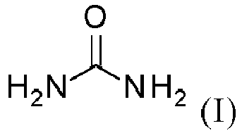
- The first composition comprises water and urea: CO(NH2)2. The first composition is typically an aqueous solution of urea. In one such embodiment the first composition consists essentially of urea and water, e.g. AdBlue® (aqueous urea solution, standardised to AUS32, also known as a diesel engine fuel (DEF)). There is already an existing market acceptance for AdBlue® as an ammonia precursor and an extensive distribution network.
- In one series of embodiments the first composition comprises at least 5, 10, 15, 20, 25, 30, 35, 40, 45 or 50wt% urea / or no more than 80, 70, 60, 50, 40, 30, 20 or 10wt% urea. The balance may be water.
- In one embodiment the first composition comprises 30 to 35wt%, 31 to 34wt%, 32 to 33wt% or approximately 32.5% urea, with the balance being water. The commercially available product AdBlue® consists of 32.5wt% urea and 67.5wt% water. This is said to be correspond closely to a eutectic mixture. In a preferred embodiment the first composition is AdBlue®.
- The first composition may be introduced into the exhaust stream in any conventional way e.g. by injection.
- The second reducing agent comprises ammonium carbamate: H2NCO2NH4. Ammonium carbamate is the ammonium salt of carbamic acid (NH2CO2H) and has the formula (II):

- Ammonium carbamate decomposes to produce ammonia and carbon dioxide. Decomposition can occur as early as 25°C, meaning that the reduction of NOx can occur even at low temperatures (c.f. 350°C for AdBlue®). This is a benefit at low temperature but leads to difficulties at higher ambient temperatures, since sealed storage is required.
- The use of ammonium carbamate solution for the selective catalytic reduction of NOx is known (
WO96/06674 - A benefit of AdBlue® is that it is very stable at ambient temperatures; it is stored in a tank in a vehicle and refilled as necessary. A passenger car may have a tank that holds 15 to 20 litres of AdBlue®. A heavy goods vehicle would have a much larger tank. It would not be safe or practical to carry such high volumes of ammonium carbamate solution. The ammonium carbamate would decompose to form ammonia, which is toxic and also flammable in sufficient quantities. Therefore a specifically designed tank would be required to maintain the vapour pressure and prevent sublimation.
WO96/06674 - In embodiments the second composition is an aqueous composition i.e. a solution of the ammonium carbamate in water. In embodiments the first composition consists of ammonium carbamate and water.
- In embodiments the second composition comprises at least 5, 10, 15, 20, 25, 30, 35, 40, 45 or 50wt% ammonium carbamate and / or no more than 70, 60, 50, 40, 45, 30, 35, 20 or 10wt% ammonium carbamate. The balance may be water.
- In embodiments the second composition comprises from 25 to 45wt%, from 30 to 44wt%, from 33 to 43wt% or approximately 42wt% ammonium carbamate. When the ammonium carbamate is produced in situ from AdBlue® (32.5wt% urea and 67.5wt% water), the resulting ammonium carbamate solution comprises approximately 42.25wt% ammonium carbamate (assuming complete conversion).
- The second composition may be introduced into the exhaust stream in any conventional way e.g. by injection.
- The suitability of the first and second compositions for reducing NOx depends on the temperature of the exhaust stream. The first composition (comprising urea) is more appropriate at higher temperatures and the second composition (comprising ammonium carbamate) is more appropriate at lower temperatures.
- The skilled person can select the threshold temperature depending on his needs. The skilled person will appreciate that the threshold temperature can be selected depending on a number of factors familiar to him including the relative financial costs of the first and second compositions (which may vary over time), the amount of NOx and other emissions that he is willing to tolerate, the quantities of the first and second compositions that are available, the amount of deposition (from urea) that he is willing to tolerate, any additional components present in the first and second compositions, and the operating conditions.
- For example, an exhaust stream temperature of at least 350°C is desirable for full decomposition of AdBlue® to form ammonia and deposits are likely to form when the temperature is less than 190°C. Therefore, if AdBlue® is employed as the first composition the skilled person may select a threshold temperature of at least 200°C.
- In one series of embodiments the threshold temperature is at least 100, 150, 200, 230, 250, 270, 300, 350 or 400°C and / or no more than 1000, 800, 600, 400, 200 or 100°C. In a particular embodiment, the threshold temperature is selected from the range 200 to 400°C.
- The process may be employed such that only the first composition or only the second composition is introduced into the exhaust stream at a given temperature i.e. the threshold temperature can act as a cut-off. In some embodiments the first composition is only introduced into the exhaust stream when the exhaust stream has a temperature at or above the threshold temperature. In some embodiments the second composition is only introduced into the exhaust stream when the exhaust stream has a temperature below the threshold temperature.
- Alternatively the process may be employed such that both of the first composition and the second composition are introduced into the exhaust stream at a given temperature.
- In some circumstances a gradual change from the second composition to the first composition as the temperature of the exhaust stream increases may be beneficial. Such an approach would avoid the risk of no reducing agent being available for even a short period of time.
- In embodiments the first composition is only introduced into the exhaust stream when the exhaust stream has temperature (the exhaust stream temperature)
- (i) at or above the threshold temperature; or
- (ii) no more than 100, 50, 20 or 10°C below the threshold temperature.
- In embodiments the second composition is only introduced into the exhaust stream when the exhaust stream has temperature (the exhaust stream temperature)
- (i) below the threshold temperature; or
- (ii) no more than 100, 50, 20 or 10°C above the threshold temperature.
- It will be understood that it is necessary to know the temperature of the exhaust stream in order to determine whether the first composition and / or the second composition should be introduced. The temperature could be measured by means of a dedicated sensor. Alternatively an approximate temperature might be inferred from the conditions. In embodiments the process additionally comprises measuring the temperature of the exhaust stream. The temperature of the exhaust stream may be compared to the threshold temperature and the first composition and / or the second composition can be selected for introduction into the exhaust stream. In embodiments the process comprises measuring the temperature of the exhaust stream and reporting the value to a programmable electronic control unit (ECU). The ECU can be programmed to release the first composition and / or the second composition into the exhaust steam, e.g. by means of a dosing valve.
- In embodiments the ammonium carbamate is prepared in situ. As discussed above, it is not practical or safe to employ ammonium carbamate solution as a direct replacement for AdBlue®. It would be necessary to transport large volumes of the solution, which is technically difficult and potentially unsafe. Instead generation of ammonium carbamate in situ allows small quantities to be prepared, optionally stored, and used as needed.
- This embodiment provides particular benefits relative to the prior art process described in
US2014/0214963 . US'963 discloses the use of a canister of metal-ammine salts, which offer a solid storage medium for ammonia. The metal-ammine acts as a "reservoir" for the ammonia and cannot be generated in situ. - In embodiments the process additionally comprises the preparation of ammonium carbamate from the first composition. The ammonium carbamate may be prepared by means of the process of the second aspect (below).
- The urea solution and the ammonium carbamate solution each produce ammonia, which reduces NOx in the exhaust stream. In embodiments the exhaust stream comprises a reduction chamber having a selective catalytic reduction (SCR) catalyst therein.
- The process comprises reducing NOx in an exhaust steam from a combustor, such as an internal combustion engine. The combustor may be stationary (e.g. a utility boiler or diesel generator) or mobile (e.g. a vehicle). The process is especially useful for on highway and off highway vehicles which currently employ SCR reduction of NOx.
- In embodiments the process comprises reducing NOx in a vehicle exhaust stream.
- In one such embodiment, the process comprises reducing NOx in a vehicle exhaust stream where the ammonium carbamate is prepared in situ i.e. on vehicle.
- According to a second aspect of the present invention there is provided a process for the preparation of ammonium carbamate comprising
providing a first reservoir having an aqueous solution of urea therein;
transferring a portion of the aqueous solution of urea along a flow path, the flow path being in communication with a second reservoir;
heating the portion of the aqueous solution of urea to produce a mixture comprising ammonia, carbon dioxide and water;
cooling the mixture to generate an aqueous solution of ammonium carbamate;
wherein each of the heating and the cooling takes place in the flow path or in the second reservoir. - It will be understood that the aqueous solution of urea and the aqueous solution of ammonium carbamate may constitute the first and second compositions of the first aspect of the invention. In embodiments only a portion of the aqueous urea solution is converted into ammonium carbamate; a volume of aqueous urea solution remains within the first reservoir.
- In one example, the process of the present invention provides 8g of ammonium carbamate solution per minute. This is sufficient to reduce 2.8g NOx.
-
WO96/06674 - The first reservoir may correspond to a conventional AdBlue® tank on a vehicle. In embodiments the first reservoir has a volume of no more than 500, 200, 100, 50, 30 or 20 litres and / or at least 10, 20 or 50 litres. In embodiments the first reservoir has a volume of 10 to 100 litres.
- The second reservoir stores the aqueous ammonium carbamate that is produced. Hence a portion of the aqueous solution of urea is transferred from the first reservoir, along the flow path, to the second reservoir and may be converted to ammonium carbamate on the way or in the second reservoir. As discussed above, it may not be safe or practical to store large volumes of aqueous ammonium carbamate. In embodiments the second reservoir has a volume of no more than 10, 8, 5, 3, 2, 1 or 0.5 litres and / or at least 0.05, 0.1, 0.2, 0.5, or 1 litres.
- In embodiments the first reservoir has a greater volume than the second reservoir. In embodiments, the volume of the first reservoir is at least 5, 10, 20, 50 or 100 times greater than the volume of the second reservoir.
- In embodiments the portion of the aqueous urea is heated by an electrical heater.
- In embodiments the portion is heated by a heat-exchanger, e.g. a heat-exchanger in communication with an exhaust stream, engine coolant or an electrical heater. It is an advantage of the present process that the ammonium carbamate can be produced when an exhaust stream is hot, using energy that would otherwise be wasted.
- In embodiments the heating comprises heating the portion of the aqueous urea solution to a temperature of at least 100, 150, 200, 250, 300, 350 or 400°C and / or no more than 1000, 800, 600 or 500°C. Higher temperatures minimise the generation of alternative decomposition products which cause deposits. However, the skilled person may be willing to tolerate some deposits to obtain ammonium carbamate at lower temperatures.
- In embodiments the heating is carried out at or above atmospheric pressure. In one embodiment heating may be carried out in a sealed environment, such that pressure increases as ammonia and carbon dioxide is generated. In another embodiment a pressure release valve may be employed to maintain a constant pressure.
- In embodiments the heating is carried out at a pressure of at least 100, 130, 150, 200, 250, 300, 500, 1000, 2000, 3000, 4000, 5000, 10000 or 15000kPa and / or no more than 200000, 150000, 100000, 50000, 10000, 5000, 4000, 3000, 2000, 1500, 1000, 800, 600, 400, 200 or 100kPa. In a particular embodiment the heating takes place at a pressure of 100 to 300kPa.
- In embodiments the heating is carried out below atmospheric pressure. In a series of such embodiments the heating is carried out at a pressure of no more than 99, 95, 90, 80 or 70kPa and/or at least 10, 30 or 50kPa.
- In embodiments heating comprises heating the portion of the aqueous solution of urea to generate ammonia and carbon dioxide in liquid water. A benefit of heating at elevated pressure is that the water in the aqueous urea solution may be kept liquid, rather than becoming a gas (steam), which encourages full decomposition of the urea.
- In embodiments the heating takes place in the flow path. In one such embodiment the flow path comprises or constitutes a decomposition chamber. In embodiments the decomposition chamber may have a volume of at least 0.05, 0.1, 0.15, 0.2, 0.3 or 0.5 litres and / or no more than 2, 1.5, 1 or 0.5 litres. Ammonia can be corrosive so the flow path should be made from a material that can withstand ammonia, especially if heating is to take place there. In one embodiment the flow path is formed from stainless steel.
- In embodiments the cooling takes place in the flow path. In one such embodiment the flow path comprises a chiller, e.g. a condenser having a coolant fluid flowing therein. Additionally or alternatively, the flow path may comprise a pressure reducing valve e.g. a constant back pressure valve. Since enthalpy is constant over the valve, expansion of a gas forces a temperature drop.
- In embodiments the cooling comprises cooling the mixture of ammonia, carbon dioxide and water to a temperature of no more than 200, 150, 100, 50, 40 or 30°C and / or at least 5, 10, 15, 20 or 25°C.
- In embodiments the cooling is carried out at or above atmospheric pressure. Ambient and higher pressures bias the reaction towards the formation of ammonium carbamate. In one embodiment cooling may be carried out in a sealed environment, such that pressure reduces as aqueous ammonium carbamate is generated. In another embodiment a pressure release valve may be employed to maintain a constant pressure.
- In embodiments the heating and the cooling take place in the flow path.
- In embodiments the heating takes place in the flow path and the cooling takes place in the second reservoir.
- In embodiments each of the heating and the cooling takes place in the second reservoir. In one such embodiment the second reservoir comprises a heat exchanger which heats the aqueous urea solution and cools the resulting mixture comprising ammonia, carbon dioxide and water.
- Ammonia can be corrosive so the second reservoir should be made from a material that can withstand ammonia, especially if heating or cooling is to take place there. In one embodiment the second reservoir is formed from stainless steel.
- In embodiments the process is carried out to produce no more than 500, 400, 300, 200, 100, 80, 60, 40, 30, 20 or 10g of ammonium carbamate solution per minute. Such quantities may not be useful in a commercial process, but may provide sufficient ammonium carbamate for a cold-start reduction of NOx.
- According to a third aspect of the present invention there is provided apparatus for delivering first and second compositions to an exhaust stream, the apparatus comprising
a first reservoir for storing a first solution and means for delivering a first composition from the first reservoir to an exhaust stream;
a second reservoir for storing a second composition and means for delivering a second composition from the second reservoir to an exhaust stream;
a flow path from the first reservoir to the second reservoir, the flow path and the second reservoir being configured to convert the first composition into the second composition. - It will be understood that the apparatus may be employed to convert aqueous urea solution (a first composition) to aqueous ammonium carbamate solution (a second composition) in accordance with the second aspect of the invention and thereby reduce NOx in accordance with the first aspect of the invention. Hence the comments above in relation to the first and second aspects of the invention may apply here.
- In embodiments the means for delivering the first composition to an exhaust stream and /or the means for delivering the second composition to an exhaust stream comprises an injector. In embodiments a single injector is employed to deliver the first composition and the second composition to an exhaust stream.
- In embodiments the apparatus additionally comprises a programmable control unit (ECU). The ECU may be programmed to deliver the first composition and / or the second composition to the exhaust stream in accordance with specific criteria. In one such embodiment the ECU controls one or more valves and / or pumps which limit the release of the first and / or second compositions into the exhaust stream. In one such embodiment the ECU controls one or more valves and /or pump which meter the transfer of the first composition into the flow path.
- In embodiments the apparatus additionally comprises a reduction chamber having a selective catalytic reduction (SCR) catalyst therein for reducing NOx in an exhaust stream. The reduction chamber will be located downstream of the first and second reservoirs.
- The reduction chamber may be a conventional reduction chamber having an SCR catalyst (e.g. WTiO2) therein. In embodiments the SCR catalyst comprises a wall flow catalyst e.g. a wall flow WTiO2 catalyst. This is useful for filtration of diesel particulates.
- In embodiments the apparatus additionally comprises an ammonia oxidation catalyst (AMOX) located downstream from the reduction chamber, to oxidize any excess ammonia.
- In embodiments the apparatus comprises a temperature sensor located in the exhaust stream to determine the exhaust stream temperature. This information can be relayed to the ECU.
- In embodiments the apparatus comprises at least one NOx sensor. In one embodiment an NOx sensor is located upstream of the first reservoir (and reduction chamber). The NOx sensor can then provide information to the ECU to determine whether NOx reduction is required. In one embodiment a further NOx sensor is located downstream of the reduction chamber. The NOx sensor can provide information to determine the efficiency of the reduction.
- In embodiments the apparatus comprises at least one ammonia sensor. In one such embodiment the ammonia sensor is located downstream from the reduction chamber (and optional AMOX) to determine whether excess ammonia is present.
- The invention also resides in fitting the apparatus of the third aspect to a combustor, e.g. a vehicle or generator. The apparatus may be fitted when the combustor (e.g. vehicle or generator) is manufactured or at a later date (retro-fitting). The system requires very little engine design alteration whilst dramatically reducing the total NOx output. Increased NOx reduction capability can also benefit other regulated emissions allowing an engine to operate at a more efficient condition reducing both CO2 and PM.
- The invention also resides in a combustor configured for the process of the first aspect; configured for the process of the second aspect; or comprising the apparatus of the third aspect. The invention also resides in a system comprising such a combustor e.g. a vehicle or generator.
- Embodiments of the invention will now be described with reference to the following figures in which:
-
Figures 1 to 6 are schematic diagrams of systems in accordance with embodiments of the invention. - Referring to
figure 1 there is shown anexhaust stream 10 containing NOx that flows from left (upstream) to right (downstream), as indicated by an arrow. The system comprises afirst reservoir 12 containing aqueous urea (e.g. an AdBlue® tank). The aqueous urea is metered into theexhaust stream 10 via aconventional delivery system 14, which comprises aninjector 16. AnECU 18 is programmed with a given threshold temperature (e.g. 300°C), such that the aqueous urea is injected into theexhaust stream 10 when the exhaust stream temperature is at or above the threshold temperature. The aqueous urea decomposes in theexhaust stream 10 to generate ammonia and carbon dioxide which passes downstream to a reduction chamber (not shown) having a selective catalytic reduction catalyst therein. The ammonia reduces the NOx in the reduction chamber. - A portion of the aqueous urea solution is released from the
first reservoir 12 and transferred via afirst valve 20 to a decomposition heat exchanger 22 (also known as a decomposition chamber). Thedecomposition heat exchanger 22 is in communication with theexhaust stream 10 and uses heat from theexhaust stream 10 to decompose the aqueous urea solution to form carbon dioxide and ammonia. The mixture comprising water, carbon dioxide and ammonia is then transferred to a sealedreservoir 24 by means of apressure reducing valve 26. The mixture is cooled by passing through thevalve 26 and also radiates heat from thereservoir 24, thereby generating ammonium carbamate solution. The sealedreservoir 24 is at lower pressure that thedecomposition heat exchanger 22 and its pressure is measured by means of apressure sensor 28. Conversion of aqueous urea to ammonium carbamate is controlled by theECU 18, which opens theflow valve 20 when required. The ammonium carbamate solution is transferred from thereservoir 24 via avalve 30 to aninjector 32 and injected into theexhaust stream 10 when the exhaust stream temperature is below the threshold temperature. The ammonium carbamate solution decomposes to form ammonia and carbon dioxide which passes downstream to a reduction chamber where the ammonia reduces NOx. - Referring to
figure 2 there is shown another exhaust system in accordance with an embodiment of the invention. The system is similar to that shown infigure 1 except that thedecomposition heat exchanger 22 is in communication with anelectrical heater 34, rather than using heat from theexhaust stream 10. The temperature of theheater 34 is measured by atemperature sensor 36, and controlled by theECU 18. - The system in
figure 3 is similar to the system offigure 1 except that it employs theinjector 16 of the conventional delivery system 14 (e.g. AdBlue® delivery system) to deliver the ammonium carbamate, rather than a dedicated ammonium carbamate injector. Hence, a second injector is not required and the apparatus is more compact. - The system of
figure 4 is similar to that infigure 1 except that aheat exchanger 38 is located in the sealedreservoir 24, rather than in the flow path between thereservoirs first reservoir 12 though thevalve 20 to thesecond reservoir 24. Theheat exchanger 38 uses heat from the exhaust system to heat the aqueous urea solution to form ammonia and carbon dioxide and subsequently cools the mixture comprising water, ammonia and carbon dioxide to form ammonium carbamate, which remains in thereservoir 24. The temperature and pressure is measured bysensors ECU 18. - The system of
figure 5 is similar to that offigure 4 except that thereservoir 24 contains anelectrical heater 40 instead of a heat exchanger. Cooling takes place by radiation from thereservoir 24. Alternatively a piezo electrical heater is employed that can also cool the mixture. Furthermore, theconventional injector 16 is employed to deliver both the urea solution and the ammonium carbamate to theexhaust stream 10, thereby making the apparatus more compact. - The system of
figure 6 is similar tofigure 3 except that adosing pump 42 is employed in place of thesecond flow valve 30. Thedosing pump 42 transfers ammonium carbamate to theinjector 16. Thedosing pump 42 ensures that the ammonium carbamate is transferred consistently, even when the pressure in thereservoir 24 is low. A dosing pump is also useful if atomisation from theinjector 16 is desired.
Claims (15)
- A process for reducing nitrogen oxides in an exhaust stream, the process comprising providing
a first composition comprising urea and water;
a second composition comprising ammonium carbamate;
an exhaust stream comprising nitrogen oxides; and
introducing the second composition into the exhaust stream when the exhaust stream has a temperature below a threshold temperature and introducing the first composition into the exhaust stream when the exhaust stream has a temperature at or above the threshold temperature. - The process of claim 1, wherein the ammonium carbamate is prepared by a process comprising
providing a first reservoir having the first composition therein;
transferring a portion of the first composition along a flow path, the flow path being in communication with a second reservoir;
heating the portion of the first composition to produce a mixture comprising ammonia, carbon dioxide and water; and
cooling the mixture to generate the second composition, the second composition comprising an aqueous solution of ammonium carbamate;
wherein each of the heating and the cooling takes place in the flow path or in the second reservoir. - The process of claim 1 or claim 2, wherein (i) the threshold temperature is at least 250°C; and/or (ii) the threshold temperature is no more than 400°C.
- The process of any one of the preceding claims wherein (i) the first composition comprises at least 20wt% urea and / or (ii) the second composition comprises at least 20wt% ammonium carbamate.
- The process of any one of the preceding claims, wherein the ammonium carbamate is prepared in situ.
- The process of claim 5, wherein the ammonium carbamate is prepared from the first composition.
- The process of any one of the preceding claims, wherein the exhaust stream is a vehicle exhaust stream.
- A process for the preparation of ammonium carbamate comprising providing a first reservoir having a first composition therein, the first composition comprising an aqueous solution of urea;
transferring a portion of the first composition along a flow path, the flow path being in communication with a second reservoir;
heating the portion of the first composition to produce a mixture comprising ammonia, carbon dioxide and water;
cooling the mixture to generate a second composition, the second composition comprising an aqueous solution of ammonium carbamate;
wherein each of the heating and the cooling takes place in the flow path or in the second reservoir. - The process of any one of claims 2 to 8, wherein (i) the volume of the first reservoir is greater than the volume of the second reservoir; and/or (ii) the second reservoir has a volume of no more than 5 litres; and/or (iii) the portion of the first composition is heated by means of a heat-exchanger in communication with the exhaust stream; and/or (iv) the cooling comprises passing the ammonia and carbon dioxide through a pressure reducing valve.
- An apparatus for delivering first and second compositions to an exhaust stream, the apparatus comprising
a first reservoir for storing a first composition and means for delivering a portion of the first composition from the first reservoir to an exhaust stream;
a second reservoir for storing a second composition and means for delivering a portion of the second composition from the second reservoir to an exhaust stream; and
a flow path from the first reservoir to the second reservoir, the flow path and the second reservoir being configured to convert the first composition into the second composition. - The apparatus of claim 10, additionally comprising a reduction chamber located downstream of the first and second reservoirs.
- The apparatus of claim 10 or 11, additionally comprising an aqueous solution of urea in the first reservoir.
- The apparatus of any one of claims 10 to 12, additionally comprising an internal combustion engine.
- A vehicle that is fitted with the apparatus of any one of claim 10 to 13.
- A process for fitting the apparatus of any one of claims 10 to 13 to a vehicle.
Priority Applications (7)
| Application Number | Priority Date | Filing Date | Title |
|---|---|---|---|
| JP2019528530A JP2020503467A (en) | 2016-12-01 | 2017-12-01 | Formation of ammonium carbamate and reduction of nitrogen oxides |
| BR112019011172A BR112019011172A2 (en) | 2016-12-01 | 2017-12-01 | process for nitrogen oxides reduction and ammonium carbamate preparation, apparatus, combustion system and vehicle |
| KR1020197018468A KR20190091480A (en) | 2016-12-01 | 2017-12-01 | Preparation of Ammonium Carbamate and Reduction of Nitrogen Oxide |
| EP17836003.8A EP3548429A1 (en) | 2016-12-01 | 2017-12-01 | Producing ammonium carbamate and reducing nitrogen oxides |
| US16/465,825 US10695719B2 (en) | 2016-12-01 | 2017-12-01 | Producing ammonium carbamate and reducing nitrogen oxides |
| CN201780079109.0A CN110099866A (en) | 2016-12-01 | 2017-12-01 | Generate aminoquinoxaline and nitrogen oxides reduction |
| PCT/EP2017/081246 WO2018100187A1 (en) | 2016-12-01 | 2017-12-01 | Producing ammonium carbamate and reducing nitrogen oxides |
Applications Claiming Priority (1)
| Application Number | Priority Date | Filing Date | Title |
|---|---|---|---|
| GB1620445.5A GB2552040B (en) | 2016-12-01 | 2016-12-01 | Process for reducing nitrogen oxides |
Publications (1)
| Publication Number | Publication Date |
|---|---|
| EP3330222A1 true EP3330222A1 (en) | 2018-06-06 |
Family
ID=58159864
Family Applications (2)
| Application Number | Title | Priority Date | Filing Date |
|---|---|---|---|
| EP17173506.1A Withdrawn EP3330222A1 (en) | 2016-12-01 | 2017-05-30 | Process for reducing nitrogen oxides |
| EP17836003.8A Withdrawn EP3548429A1 (en) | 2016-12-01 | 2017-12-01 | Producing ammonium carbamate and reducing nitrogen oxides |
Family Applications After (1)
| Application Number | Title | Priority Date | Filing Date |
|---|---|---|---|
| EP17836003.8A Withdrawn EP3548429A1 (en) | 2016-12-01 | 2017-12-01 | Producing ammonium carbamate and reducing nitrogen oxides |
Country Status (8)
| Country | Link |
|---|---|
| US (1) | US10695719B2 (en) |
| EP (2) | EP3330222A1 (en) |
| JP (1) | JP2020503467A (en) |
| KR (1) | KR20190091480A (en) |
| CN (1) | CN110099866A (en) |
| BR (1) | BR112019011172A2 (en) |
| GB (1) | GB2552040B (en) |
| WO (1) | WO2018100187A1 (en) |
Cited By (10)
| Publication number | Priority date | Publication date | Assignee | Title |
|---|---|---|---|---|
| EP3650667A1 (en) * | 2018-11-08 | 2020-05-13 | Faurecia Emissions Control Technologies, USA, LLC | Automotive exhaust aftertreatment sytem having onboard ammonia reactor with heated doser |
| EP3650666A1 (en) * | 2018-11-08 | 2020-05-13 | Faurecia Emissions Control Technologies, USA, LLC | Automotive exhaust aftertreatment system having onboard ammonia reactor with hybrid heating |
| US10876454B2 (en) | 2018-11-08 | 2020-12-29 | Faurecia Emissions Control Technologies, Usa, Llc | Automotive exhaust aftertreatment system with multi-reductant injection and doser controls |
| US11022014B1 (en) | 2020-04-28 | 2021-06-01 | Faurecia Emissions Control Technologies, Usa, Llc | Exhaust aftertreatment system with heated flash-boiling doser |
| US11092054B1 (en) | 2020-04-29 | 2021-08-17 | Faurecia Emissions Control Technologies, Usa, Llc | Flash-boiling doser with thermal transfer helix |
| US11193413B2 (en) | 2019-12-12 | 2021-12-07 | Faurecia Emissions Control Technologies, Usa, Llc | Exhaust aftertreatment system with virtual temperature determination and control |
| US11225894B1 (en) | 2020-06-30 | 2022-01-18 | Faurecia Emissions Control Technologies, Usa, Llc | Exhaust aftertreatment system with thermally controlled reagent doser |
| US11319853B2 (en) | 2020-03-31 | 2022-05-03 | Faurecia Emissions Control Technologies, Usa, Llc | Automotive exhaust aftertreatment system with doser |
| US11384667B2 (en) | 2020-05-29 | 2022-07-12 | Faurecia Emissions Control Technologies, Usa, Llc | Exhaust aftertreatment system with heated dosing control |
| US11511239B2 (en) | 2020-04-29 | 2022-11-29 | Faurecia Emissions Control Technologies, Usa, Llc | Heated flash-boiling doser with integrated helix |
Families Citing this family (1)
| Publication number | Priority date | Publication date | Assignee | Title |
|---|---|---|---|---|
| GB2576511A (en) * | 2018-08-20 | 2020-02-26 | Univ Loughborough | Producing ammonium carbamate and reducing nitrogen oxides |
Citations (11)
| Publication number | Priority date | Publication date | Assignee | Title |
|---|---|---|---|---|
| GB345494A (en) * | 1930-03-24 | 1931-03-26 | Ig Farbenindustrie Ag | Improvements in the manufacture and production of ammonium carbamate |
| GB757016A (en) * | 1952-03-11 | 1956-09-12 | Montedison Spa | Process for the production of ammonium carbamate |
| GB756934A (en) * | 1952-03-11 | 1956-09-12 | Montedison Spa | Process for the production of urea and ammonium carbamate |
| EP0524953B1 (en) * | 1990-03-07 | 1995-06-21 | Fuel Tech, Inc. | Process for reducing nitrogen oxides without generating nitrous oxide |
| WO1999056858A2 (en) * | 1998-04-30 | 1999-11-11 | Siemens Aktiengesellschaft | Method and device for catalytic reduction of nitrogen oxide |
| US20010053342A1 (en) * | 1997-07-03 | 2001-12-20 | Armin Marko | Method and device for selective catalytic nox reduction |
| WO2008020207A1 (en) * | 2006-08-15 | 2008-02-21 | Imi Vision Limited | Exhaust gas treatment |
| US20110110841A1 (en) * | 2007-08-24 | 2011-05-12 | Powerspan Corp | Method and apparatus for producing ammonium carbonate from urea |
| US20140241963A1 (en) * | 2011-09-06 | 2014-08-28 | International Engine Intellectual Property Company, Llc | Cold start startup unit for urea-based systems |
| EP2865860A1 (en) * | 2013-10-28 | 2015-04-29 | Cummins Emission Solutions Inc. | Systems and methods for control of engine NOx emissions using liquid and dry reductant sources |
| US20160153335A1 (en) * | 2014-11-27 | 2016-06-02 | Toyota Jidosha Kabushiki Kaisha | Exhaust gas purification apparatus of internal combustion engine |
Family Cites Families (12)
| Publication number | Priority date | Publication date | Assignee | Title |
|---|---|---|---|---|
| IT1037576B (en) | 1975-04-23 | 1979-11-20 | Snam Progetti | Ammonium carbonate condensation in urea synthesis - by contacting liq. and vapour phases in a horizontal heat exchanger (NL261076) |
| IL49998A (en) | 1976-07-08 | 1979-11-30 | Snam Progetti | Method of formation of ammonium carbamate solution |
| US4777024A (en) * | 1987-03-06 | 1988-10-11 | Fuel Tech, Inc. | Multi-stage process for reducing the concentration of pollutants in an effluent |
| TW278050B (en) | 1994-08-29 | 1996-06-11 | Nalco Fuel Tech | |
| JP2004536011A (en) | 2001-07-24 | 2004-12-02 | ディーエスエム アイピー アセッツ ビー.ブイ. | Method for obtaining an ammonium carbamate solution from a gas mixture comprising NH3, H2O and CO2 |
| CA2606784C (en) * | 2005-05-13 | 2013-07-30 | Dsm Ip Assets B.V. | Method for concentrating an aqueous ammonium carbamate stream |
| EP1918274A1 (en) * | 2006-11-04 | 2008-05-07 | Urea Casale S.A. | Integrated process for urea and melamine production |
| BR112013003925A2 (en) * | 2010-08-23 | 2016-06-07 | Univ Ohio | "Combustion engine exhaust gas treatment system, ammonia generator and method for supplying the system with nh3" |
| US8844269B2 (en) | 2012-03-16 | 2014-09-30 | Cummins Inc. | Aftertreatment system and method for pre-decomposed reductant solution |
| CN103437865B (en) | 2013-07-25 | 2015-12-09 | 吉林大学 | A kind of automotive SCR system ammonia production method and device |
| US9624111B2 (en) * | 2014-12-10 | 2017-04-18 | Ethan Novek | Integrated process for carbon capture and energy production |
| US20190234283A1 (en) * | 2018-01-31 | 2019-08-01 | International Engine Intellectual Property Company, Llc | ENGINE OUT NOx REDUCTION USING ENHANCED DEF |
-
2016
- 2016-12-01 GB GB1620445.5A patent/GB2552040B/en not_active Expired - Fee Related
-
2017
- 2017-05-30 EP EP17173506.1A patent/EP3330222A1/en not_active Withdrawn
- 2017-12-01 US US16/465,825 patent/US10695719B2/en not_active Expired - Fee Related
- 2017-12-01 WO PCT/EP2017/081246 patent/WO2018100187A1/en not_active Ceased
- 2017-12-01 JP JP2019528530A patent/JP2020503467A/en active Pending
- 2017-12-01 EP EP17836003.8A patent/EP3548429A1/en not_active Withdrawn
- 2017-12-01 BR BR112019011172A patent/BR112019011172A2/en not_active Application Discontinuation
- 2017-12-01 KR KR1020197018468A patent/KR20190091480A/en not_active Withdrawn
- 2017-12-01 CN CN201780079109.0A patent/CN110099866A/en active Pending
Patent Citations (11)
| Publication number | Priority date | Publication date | Assignee | Title |
|---|---|---|---|---|
| GB345494A (en) * | 1930-03-24 | 1931-03-26 | Ig Farbenindustrie Ag | Improvements in the manufacture and production of ammonium carbamate |
| GB757016A (en) * | 1952-03-11 | 1956-09-12 | Montedison Spa | Process for the production of ammonium carbamate |
| GB756934A (en) * | 1952-03-11 | 1956-09-12 | Montedison Spa | Process for the production of urea and ammonium carbamate |
| EP0524953B1 (en) * | 1990-03-07 | 1995-06-21 | Fuel Tech, Inc. | Process for reducing nitrogen oxides without generating nitrous oxide |
| US20010053342A1 (en) * | 1997-07-03 | 2001-12-20 | Armin Marko | Method and device for selective catalytic nox reduction |
| WO1999056858A2 (en) * | 1998-04-30 | 1999-11-11 | Siemens Aktiengesellschaft | Method and device for catalytic reduction of nitrogen oxide |
| WO2008020207A1 (en) * | 2006-08-15 | 2008-02-21 | Imi Vision Limited | Exhaust gas treatment |
| US20110110841A1 (en) * | 2007-08-24 | 2011-05-12 | Powerspan Corp | Method and apparatus for producing ammonium carbonate from urea |
| US20140241963A1 (en) * | 2011-09-06 | 2014-08-28 | International Engine Intellectual Property Company, Llc | Cold start startup unit for urea-based systems |
| EP2865860A1 (en) * | 2013-10-28 | 2015-04-29 | Cummins Emission Solutions Inc. | Systems and methods for control of engine NOx emissions using liquid and dry reductant sources |
| US20160153335A1 (en) * | 2014-11-27 | 2016-06-02 | Toyota Jidosha Kabushiki Kaisha | Exhaust gas purification apparatus of internal combustion engine |
Cited By (14)
| Publication number | Priority date | Publication date | Assignee | Title |
|---|---|---|---|---|
| US10876454B2 (en) | 2018-11-08 | 2020-12-29 | Faurecia Emissions Control Technologies, Usa, Llc | Automotive exhaust aftertreatment system with multi-reductant injection and doser controls |
| CN111156070A (en) * | 2018-11-08 | 2020-05-15 | 佛吉亚排放控制技术美国有限公司 | Automotive exhaust aftertreatment system with on-board ammonia reactor with hybrid heating |
| CN111156074A (en) * | 2018-11-08 | 2020-05-15 | 佛吉亚排放控制技术美国有限公司 | Automotive exhaust aftertreatment system with on-board ammonia reactor with heated feeder |
| US10683787B2 (en) | 2018-11-08 | 2020-06-16 | Faurecia Emissions Control Technologies, Usa, Llc | Automotive exhaust aftertreatment system having onboard ammonia reactor with hybrid heating |
| US10767529B2 (en) | 2018-11-08 | 2020-09-08 | Faurecia Emissions Control Technologies, Usa, Llc | Automotive exhaust aftertreatment system having onboard ammonia reactor with heated doser |
| EP3650667A1 (en) * | 2018-11-08 | 2020-05-13 | Faurecia Emissions Control Technologies, USA, LLC | Automotive exhaust aftertreatment sytem having onboard ammonia reactor with heated doser |
| EP3650666A1 (en) * | 2018-11-08 | 2020-05-13 | Faurecia Emissions Control Technologies, USA, LLC | Automotive exhaust aftertreatment system having onboard ammonia reactor with hybrid heating |
| US11193413B2 (en) | 2019-12-12 | 2021-12-07 | Faurecia Emissions Control Technologies, Usa, Llc | Exhaust aftertreatment system with virtual temperature determination and control |
| US11319853B2 (en) | 2020-03-31 | 2022-05-03 | Faurecia Emissions Control Technologies, Usa, Llc | Automotive exhaust aftertreatment system with doser |
| US11022014B1 (en) | 2020-04-28 | 2021-06-01 | Faurecia Emissions Control Technologies, Usa, Llc | Exhaust aftertreatment system with heated flash-boiling doser |
| US11092054B1 (en) | 2020-04-29 | 2021-08-17 | Faurecia Emissions Control Technologies, Usa, Llc | Flash-boiling doser with thermal transfer helix |
| US11511239B2 (en) | 2020-04-29 | 2022-11-29 | Faurecia Emissions Control Technologies, Usa, Llc | Heated flash-boiling doser with integrated helix |
| US11384667B2 (en) | 2020-05-29 | 2022-07-12 | Faurecia Emissions Control Technologies, Usa, Llc | Exhaust aftertreatment system with heated dosing control |
| US11225894B1 (en) | 2020-06-30 | 2022-01-18 | Faurecia Emissions Control Technologies, Usa, Llc | Exhaust aftertreatment system with thermally controlled reagent doser |
Also Published As
| Publication number | Publication date |
|---|---|
| KR20190091480A (en) | 2019-08-06 |
| GB2552040B (en) | 2018-08-01 |
| WO2018100187A1 (en) | 2018-06-07 |
| US10695719B2 (en) | 2020-06-30 |
| GB2552040A (en) | 2018-01-10 |
| US20200023312A1 (en) | 2020-01-23 |
| BR112019011172A2 (en) | 2019-10-08 |
| CN110099866A (en) | 2019-08-06 |
| JP2020503467A (en) | 2020-01-30 |
| GB201620445D0 (en) | 2017-01-18 |
| EP3548429A1 (en) | 2019-10-09 |
Similar Documents
| Publication | Publication Date | Title |
|---|---|---|
| GB2552040A (en) | Process for reducing nitrogen oxides | |
| GB2562178A (en) | Process for reducing nitrogen oxides | |
| CN104847459B (en) | internal combustion engine | |
| CN103748329B (en) | Cold start starter unit for urea based systems | |
| KR102309224B1 (en) | Method for purifying diesel engine exhaust gases | |
| US8518354B2 (en) | Diesel exhaust fluid formulation having a high ammonium content and a low freezing point | |
| US20100293927A1 (en) | Method and device for safe and controlled delivery of ammonia from a solid ammonia storage medium | |
| CA2806591A1 (en) | Method and devices for heating urea-containing materials in vehicle emission control system | |
| JP2005507985A (en) | Method and apparatus for reducing nitrogen oxides in exhaust gas | |
| Johannessen et al. | Ammonia storage and delivery systems for automotive NOx aftertreatment | |
| EP2662549B1 (en) | Method and system for purifying the exhaust gases of a combustion engine. | |
| CN107327332B (en) | SSCR system based on solid ammonia storage material | |
| JP2002510005A (en) | Method and apparatus for catalytic reduction of nitrogen oxides in exhaust gas of combustion equipment | |
| US9644515B2 (en) | Gaseous ammonia injection system | |
| Hesser et al. | SCR technology for NOx reduction: series experience and state of development | |
| US20140325964A1 (en) | Ammonia gas pressure booster | |
| KR20180076684A (en) | Reductant supply system and method for supplying reductant | |
| WO2018041754A1 (en) | System and method for increasing the urea concentration of an aqueous solution on-board a vehicle | |
| CN105074150B (en) | A flow manifold system | |
| JP2010506079A (en) | Method and apparatus for providing a reducing agent precursor | |
| Wang et al. | An Experimental Comparative Study of a Solid-State Ammonia Dosing System and Traditional Adblue Dosing System on a Heavy-Duty Diesel Engine SCR System | |
| Hüthwohl et al. | Urea Solution Dosing System for Improved Catalyst Efficiency | |
| KR20220028981A (en) | Gas-state Amonia Supply Apparatus from Solid-state Amonia | |
| KR20200078015A (en) | A System for Purification of NOx Emissions | |
| WO2009098484A1 (en) | Urea-hydrolysis and injection system for exhaust gas treatment |
Legal Events
| Date | Code | Title | Description |
|---|---|---|---|
| PUAI | Public reference made under article 153(3) epc to a published international application that has entered the european phase |
Free format text: ORIGINAL CODE: 0009012 |
|
| AK | Designated contracting states |
Kind code of ref document: A1 Designated state(s): AL AT BE BG CH CY CZ DE DK EE ES FI FR GB GR HR HU IE IS IT LI LT LU LV MC MK MT NL NO PL PT RO RS SE SI SK SM TR |
|
| AX | Request for extension of the european patent |
Extension state: BA ME |
|
| STAA | Information on the status of an ep patent application or granted ep patent |
Free format text: STATUS: THE APPLICATION IS DEEMED TO BE WITHDRAWN |
|
| 18D | Application deemed to be withdrawn |
Effective date: 20181207 |