EP3330219A1 - Dispensing apparatus provided with a cooling unit - Google Patents
Dispensing apparatus provided with a cooling unit Download PDFInfo
- Publication number
- EP3330219A1 EP3330219A1 EP16201501.0A EP16201501A EP3330219A1 EP 3330219 A1 EP3330219 A1 EP 3330219A1 EP 16201501 A EP16201501 A EP 16201501A EP 3330219 A1 EP3330219 A1 EP 3330219A1
- Authority
- EP
- European Patent Office
- Prior art keywords
- cooling
- foils
- web
- cartridge
- mesh
- Prior art date
- Legal status (The legal status is an assumption and is not a legal conclusion. Google has not performed a legal analysis and makes no representation as to the accuracy of the status listed.)
- Ceased
Links
- 238000001816 cooling Methods 0.000 title claims abstract description 188
- 239000011888 foil Substances 0.000 claims abstract description 67
- 239000007788 liquid Substances 0.000 claims abstract description 47
- 239000000463 material Substances 0.000 claims abstract description 46
- 230000037361 pathway Effects 0.000 claims abstract description 25
- 239000012530 fluid Substances 0.000 claims abstract description 16
- 238000004891 communication Methods 0.000 claims abstract description 15
- 235000013361 beverage Nutrition 0.000 claims description 62
- 239000003085 diluting agent Substances 0.000 claims description 18
- 235000021557 concentrated beverage Nutrition 0.000 claims description 8
- 238000003780 insertion Methods 0.000 claims description 7
- 230000037431 insertion Effects 0.000 claims description 7
- 238000002156 mixing Methods 0.000 claims description 7
- 230000001939 inductive effect Effects 0.000 claims description 6
- 239000007769 metal material Substances 0.000 claims description 6
- 229910052782 aluminium Inorganic materials 0.000 claims description 5
- XAGFODPZIPBFFR-UHFFFAOYSA-N aluminium Chemical compound [Al] XAGFODPZIPBFFR-UHFFFAOYSA-N 0.000 claims description 5
- 239000004411 aluminium Substances 0.000 claims description 4
- 238000011144 upstream manufacturing Methods 0.000 description 16
- 235000013405 beer Nutrition 0.000 description 10
- 230000008878 coupling Effects 0.000 description 10
- 238000010168 coupling process Methods 0.000 description 10
- 238000005859 coupling reaction Methods 0.000 description 10
- 238000010079 rubber tapping Methods 0.000 description 7
- XLYOFNOQVPJJNP-UHFFFAOYSA-N water Substances O XLYOFNOQVPJJNP-UHFFFAOYSA-N 0.000 description 7
- 230000008901 benefit Effects 0.000 description 6
- 239000007789 gas Substances 0.000 description 5
- LYCAIKOWRPUZTN-UHFFFAOYSA-N Ethylene glycol Chemical compound OCCO LYCAIKOWRPUZTN-UHFFFAOYSA-N 0.000 description 4
- WYTGDNHDOZPMIW-RCBQFDQVSA-N alstonine Natural products C1=CC2=C3C=CC=CC3=NC2=C2N1C[C@H]1[C@H](C)OC=C(C(=O)OC)[C@H]1C2 WYTGDNHDOZPMIW-RCBQFDQVSA-N 0.000 description 4
- 239000003507 refrigerant Substances 0.000 description 4
- 238000004026 adhesive bonding Methods 0.000 description 3
- 230000007423 decrease Effects 0.000 description 3
- 239000010410 layer Substances 0.000 description 3
- 239000002184 metal Substances 0.000 description 3
- 229910052751 metal Inorganic materials 0.000 description 3
- -1 polyethylene Polymers 0.000 description 3
- 238000012546 transfer Methods 0.000 description 3
- 238000003466 welding Methods 0.000 description 3
- IJGRMHOSHXDMSA-UHFFFAOYSA-N Atomic nitrogen Chemical compound N#N IJGRMHOSHXDMSA-UHFFFAOYSA-N 0.000 description 2
- CURLTUGMZLYLDI-UHFFFAOYSA-N Carbon dioxide Chemical compound O=C=O CURLTUGMZLYLDI-UHFFFAOYSA-N 0.000 description 2
- GXCLVBGFBYZDAG-UHFFFAOYSA-N N-[2-(1H-indol-3-yl)ethyl]-N-methylprop-2-en-1-amine Chemical compound CN(CCC1=CNC2=C1C=CC=C2)CC=C GXCLVBGFBYZDAG-UHFFFAOYSA-N 0.000 description 2
- 230000005679 Peltier effect Effects 0.000 description 2
- 239000004698 Polyethylene Substances 0.000 description 2
- 238000005219 brazing Methods 0.000 description 2
- WGCNASOHLSPBMP-UHFFFAOYSA-N hydroxyacetaldehyde Natural products OCC=O WGCNASOHLSPBMP-UHFFFAOYSA-N 0.000 description 2
- 238000000034 method Methods 0.000 description 2
- 229920000573 polyethylene Polymers 0.000 description 2
- 239000010409 thin film Substances 0.000 description 2
- RYGMFSIKBFXOCR-UHFFFAOYSA-N Copper Chemical compound [Cu] RYGMFSIKBFXOCR-UHFFFAOYSA-N 0.000 description 1
- 239000004743 Polypropylene Substances 0.000 description 1
- CDBYLPFSWZWCQE-UHFFFAOYSA-L Sodium Carbonate Chemical compound [Na+].[Na+].[O-]C([O-])=O CDBYLPFSWZWCQE-UHFFFAOYSA-L 0.000 description 1
- 239000005030 aluminium foil Substances 0.000 description 1
- QVGXLLKOCUKJST-UHFFFAOYSA-N atomic oxygen Chemical compound [O] QVGXLLKOCUKJST-UHFFFAOYSA-N 0.000 description 1
- 230000001580 bacterial effect Effects 0.000 description 1
- 230000004888 barrier function Effects 0.000 description 1
- 230000015572 biosynthetic process Effects 0.000 description 1
- 229910002092 carbon dioxide Inorganic materials 0.000 description 1
- 239000001569 carbon dioxide Substances 0.000 description 1
- 235000014171 carbonated beverage Nutrition 0.000 description 1
- 239000003795 chemical substances by application Substances 0.000 description 1
- 235000019987 cider Nutrition 0.000 description 1
- 229910052802 copper Inorganic materials 0.000 description 1
- 239000010949 copper Substances 0.000 description 1
- 230000001419 dependent effect Effects 0.000 description 1
- 238000013461 design Methods 0.000 description 1
- 230000001627 detrimental effect Effects 0.000 description 1
- 238000009413 insulation Methods 0.000 description 1
- 239000012774 insulation material Substances 0.000 description 1
- 238000012423 maintenance Methods 0.000 description 1
- 238000004519 manufacturing process Methods 0.000 description 1
- 230000013011 mating Effects 0.000 description 1
- 239000000203 mixture Substances 0.000 description 1
- 230000007935 neutral effect Effects 0.000 description 1
- 229910052757 nitrogen Inorganic materials 0.000 description 1
- 239000001301 oxygen Substances 0.000 description 1
- 229910052760 oxygen Inorganic materials 0.000 description 1
- 239000013047 polymeric layer Substances 0.000 description 1
- 229920000098 polyolefin Polymers 0.000 description 1
- 229920001155 polypropylene Polymers 0.000 description 1
- 238000003825 pressing Methods 0.000 description 1
- 230000008569 process Effects 0.000 description 1
- 230000001737 promoting effect Effects 0.000 description 1
- BALXUFOVQVENIU-KXNXZCPBSA-N pseudoephedrine hydrochloride Chemical compound [H+].[Cl-].CN[C@@H](C)[C@@H](O)C1=CC=CC=C1 BALXUFOVQVENIU-KXNXZCPBSA-N 0.000 description 1
- 230000009467 reduction Effects 0.000 description 1
- 238000005057 refrigeration Methods 0.000 description 1
- 235000019640 taste Nutrition 0.000 description 1
Images


Classifications
-
- B—PERFORMING OPERATIONS; TRANSPORTING
- B67—OPENING, CLOSING OR CLEANING BOTTLES, JARS OR SIMILAR CONTAINERS; LIQUID HANDLING
- B67D—DISPENSING, DELIVERING OR TRANSFERRING LIQUIDS, NOT OTHERWISE PROVIDED FOR
- B67D1/00—Apparatus or devices for dispensing beverages on draught
- B67D1/08—Details
- B67D1/0857—Cooling arrangements
- B67D1/0858—Cooling arrangements using compression systems
- B67D1/0861—Cooling arrangements using compression systems the evaporator acting through an intermediate heat transfer means
- B67D1/0862—Cooling arrangements using compression systems the evaporator acting through an intermediate heat transfer means in the form of a cold plate or a cooling block
-
- B—PERFORMING OPERATIONS; TRANSPORTING
- B67—OPENING, CLOSING OR CLEANING BOTTLES, JARS OR SIMILAR CONTAINERS; LIQUID HANDLING
- B67D—DISPENSING, DELIVERING OR TRANSFERRING LIQUIDS, NOT OTHERWISE PROVIDED FOR
- B67D1/00—Apparatus or devices for dispensing beverages on draught
- B67D1/0042—Details of specific parts of the dispensers
-
- B—PERFORMING OPERATIONS; TRANSPORTING
- B67—OPENING, CLOSING OR CLEANING BOTTLES, JARS OR SIMILAR CONTAINERS; LIQUID HANDLING
- B67D—DISPENSING, DELIVERING OR TRANSFERRING LIQUIDS, NOT OTHERWISE PROVIDED FOR
- B67D1/00—Apparatus or devices for dispensing beverages on draught
- B67D1/08—Details
- B67D1/0857—Cooling arrangements
- B67D1/0869—Cooling arrangements using solid state elements, e.g. Peltier cells
-
- F—MECHANICAL ENGINEERING; LIGHTING; HEATING; WEAPONS; BLASTING
- F25—REFRIGERATION OR COOLING; COMBINED HEATING AND REFRIGERATION SYSTEMS; HEAT PUMP SYSTEMS; MANUFACTURE OR STORAGE OF ICE; LIQUEFACTION SOLIDIFICATION OF GASES
- F25D—REFRIGERATORS; COLD ROOMS; ICE-BOXES; COOLING OR FREEZING APPARATUS NOT OTHERWISE PROVIDED FOR
- F25D31/00—Other cooling or freezing apparatus
- F25D31/002—Liquid coolers, e.g. beverage cooler
-
- F—MECHANICAL ENGINEERING; LIGHTING; HEATING; WEAPONS; BLASTING
- F28—HEAT EXCHANGE IN GENERAL
- F28F—DETAILS OF HEAT-EXCHANGE AND HEAT-TRANSFER APPARATUS, OF GENERAL APPLICATION
- F28F3/00—Plate-like or laminated elements; Assemblies of plate-like or laminated elements
- F28F3/12—Elements constructed in the shape of a hollow panel, e.g. with channels
-
- B—PERFORMING OPERATIONS; TRANSPORTING
- B67—OPENING, CLOSING OR CLEANING BOTTLES, JARS OR SIMILAR CONTAINERS; LIQUID HANDLING
- B67D—DISPENSING, DELIVERING OR TRANSFERRING LIQUIDS, NOT OTHERWISE PROVIDED FOR
- B67D2210/00—Indexing scheme relating to aspects and details of apparatus or devices for dispensing beverages on draught or for controlling flow of liquids under gravity from storage containers for dispensing purposes
- B67D2210/00028—Constructional details
- B67D2210/00031—Housing
- B67D2210/00034—Modules
Definitions
- the present invention concerns a dispensing apparatus for domestic use or of the type found in pubs and bars for dispensing a liquid, typically a beverage such as a beer or other carbonated beverages which are to be served at a low temperature.
- a liquid typically a beverage such as a beer or other carbonated beverages which are to be served at a low temperature.
- the dispensing apparatus of the present invention is provided with a cooling cartridge which can be engaged into a cooling unit and thus form a section of a dispensing tube which is in thermal contact with cooling plates mounted in the cooling unit.
- beverage or beverage components must often be cooled prior to or upon dispensing. This is the case for dispensing malt based beverages, such as beer, or any soda.
- beverage dispensers comprise a cooled compartment for storing and cooling a container or reservoir.
- a common cooling system is based on the compression-expansion of a refrigerant gas of the type used in household refrigerators.
- Thermoelectric cooling systems using the Peltier effect have also been proposed in the art for cooling a container stored in a dispensing apparatus.
- One disadvantage of cooling the whole container/reservoir is that when an empty container must be replaced by a new one or when a reservoir needs to be refilled, it takes considerable time to bring the content of the new container or refilled reservoir down to the desired low temperature.
- a solution to this problem is of course to constantly store a full container in a cooled compartment so that it can be used immediately after being loaded into a dispensing apparatus in replacement of an empty container.
- This solution requires the investment of an additional cooling compartment for storing cooled containers in the wait of being loaded, and requires extra work to store a new container into the cooled compartment after having loaded a new cooled container onto the dispensing apparatus.
- Cooling only the volume of beverage flowing through the dispensing tube clearly has many potential advantages: no need to pre-cool a container in reserve as discussed supra, the volume of liquid being cooled is restricted to the volume being dispensed or even less, etc. These advantages are, however, difficult to attain, because of the numerous challenges of such process. It must be taken into consideration that the dispensing tube must be cleaned or changed at regular intervals, either because the type of beverage (type of beer) changes from one container to the other, or because with time bacterial deposits may form in a dispensing tube.
- beer must be dispensed at a relatively high flow rate, of typically 2 oz / s or 3.5 l / min, and it is difficult to extract all the thermal energy required to bring the temperature of the beverage to the desired value at such flow rates.
- the dispensing tube of a dispensing apparatus bringing in fluid communication the interior of a container/reservoir with a tapping valve comprises a serpentine or coil dipped into a vessel of iced water or any other secondary refrigerant such as glycol.
- a vessel of iced water occupies a substantial space which is often scarce behind a bar counter or at home.
- the temperature of the iced water is limited to zero degree Celsius (0°C).
- the level of ice and water must be controlled and ice refilled at regular intervals.
- a compressor can be used to form ice, so that the vessel needs not be refilled. Subzero temperatures can be reached with e.g., glycol.
- the coil or serpentine is usually made of copper or other heat conductive metal and must be cleaned at regular intervals, which is not easy in view of the coiled geometry of the serpentine.
- thermoelectric cooling systems have the great advantage of not requiring any refrigerant gas, nor any source of cold refrigerant liquid and only require to be plugged to a source of power.
- beverage dispensing apparatuses comprising a thermoelectric cooling system are disclosed in EP1188995 .
- a dispensing apparatus comprising a Peltier or thermoelectric cooling system for cooling a section of a dispensing tube
- a dispensing tube comprises a section of deformable walls disposed in a passage extending through a cooling block cooled by a Peltier cooling system.
- the deformability of the material of the disposable tube is such that the outer surface of the wall of the tube abuts against the inner surface of said passage when the beverage is pressurized. This ensures a better thermal contact between the cooling block and the dispensing tube.
- the passage through the cooling blocks comprises successive chambers separated from one another by thin passages.
- JP2002046799 discloses a domestic beverage dispensing device comprising a detachable cooling means placed in tight contact with a flexible dispensing tube, so as to allow the beer supplied from the barrel to be cooled and supplied at an appropriate temperature.
- the cooling means comprises a gelatinous cold-insulation agent filled in a predetermined container.
- a wall surface of the cooling member is formed with a guide for placing the flexible dispensing tube.
- the present invention concerns a cooling unit for a beverage dispensing apparatus, comprising:
- the web or mesh of material disposed between both foils defining a non-rectilinear trajectory to the liquid pathway.
- the web or mesh of material disposed between both foils comprising a perimeter wall defining the perimeter of the cooling cartridge with both foils sealed to the perimeter wall, the web or mesh extending in the inner area defining a non-rectilinear trajectory of the liquid pathway between the foils.
- the part of the foils situated in the inner area is stretchable or has dimensions larger than the inner area, such as to allow that the foils are at least locally spaced apart from the contact zones wall parts in a direction perpendicular to the cooling surfaces when the inner volume of the liquid line is pressurized, thereby creating short-cuts in the trajectory of the channel in the cooling unit.
- the distance separating the first surface and second surface of the first and second cooling plates can preferably be varied
- the cooling plates When spaced at a distance dc, the cooling plates preferably press the foils against the contact zones of the web or mesh.
- baffles or turbulence inducing elements are provided in the non-rectilinear trajectory of the liquid pathway.
- the foils In order to make the cooling unit compact, it is preferred to manufacture the foils in a material having good heat transfer rates such as a metallic material, for example aluminium.
- a material having good heat transfer rates such as a metallic material, for example aluminium.
- the web or mesh can be made in either a polymeric material or a metallic material.
- wall parts of the web defining the contac zones are as thin as possible. Not or only at distinct points welding or glueing the foils to the wall parts of the web allows for reducing the thickness of these wall parts to 2 mm or less, preferably 1 mm or less.
- the present invention also concerns a beverage dispensing apparatus comprising a cooling unit according to the present invention, such beverage dispensing apparatus can be of any type, including a domestic apparatus or an on-trade apparatus for use in eg. bars, hotels or pubs.
- the dispensing apparatus is preferably designed for dispensing carbonated malt-based beverages.
- the dispensing apparatus is of a type comprising a source of a concentrated beverage component fluidly connected to a dispense tap by a first dispense line and a source of a diluent fluidly connected to the dispense tap by a second dispense line, the cooling unit integrated in the apparatus for cooling the concentrated beverage component and/or diluent when flowing to the first and/or second dispense line.
- the dispensing apparatus may comprise a mixing unit having an inlet in fluid communication with the first and second dispense lines and an outlet in fluid communication with the dispense tap, in which case, the cooling unit is preferably integrated in the apparatus for cooling the concentrated beverage component and/or diluent downstream the mixing unit.
- the dispensing apparatus may comprise a carbonation unit, preferably an in-line carbonation unit, having an inlet in fluid communication with the source of diluent and an outlet in fluid communication with the dispense tap, in which case, the cooling unit is preferably integrated in the apparatus for cooling the diluent downstream the carbonation unit.
- a carbonation unit preferably an in-line carbonation unit, having an inlet in fluid communication with the source of diluent and an outlet in fluid communication with the dispense tap, in which case, the cooling unit is preferably integrated in the apparatus for cooling the diluent downstream the carbonation unit.
- the present invention concerns a beverage dispensing apparatus and a kit-in-parts for forming such a beverage dispensing apparatus comprising the following elements:
- the gist of the invention is that the foils are not or only at distinct locations attached to the wall parts or contact zones of the web or mesh, thereby creating short-cuts in the trajectory of the channel in the cooling unit promoting a turbulent liquid flow in the cartridge and hence improving cooling efficiency of the liquid and/or allowing the web wall parts to be dimensioned to have a cross-section in the plane of the cooling surfaces that is as small as possible to increase the contact area between the liquid to be cooled and the foils and on the cooling surface, which in turn are in contact with the cooling surfaces.
- the footprint of the contact zones, in this case the web walls is minimized without influencing the length of the channel in the cartridge.
- a liquid pathway or in this case channel can be defined by an axial direction, parallel to an axial axis, which defines the trajectory of the channel (which is not necessarily rectilinear).
- the axial axis often corresponds to an axis of symmetry of the channel or, for non rectilinear channels, is often defined by the succession of points of symmetry put side by side to form a continuous line.
- a channel is also defined by radial directions, including any direction normal to the axial axis.
- the axial axis is the axis of revolution of the cylinder and the radial directions are defined by any radius of a cross- section normal to the axial axis.
- the first and second foils are not welded or glued to the web wall parts and allow as such short cuts to be created in the channel of the cartridge.
- the at least one radial direction along which the channel must be flexible is thus defined in use by the moving direction of the foils in view of the web wall parts.
- the cooling unit comprises a cold source (2C) for cooling the first and second cooling plates.
- a cold source known in the art can be used to cool the first and second cooling plates.
- compressor based refrigeration systems or thermoelectric cooling systems are well suited for cooling the cooling plates. Any other method can, however, be used without departing from the present invention.
- the cooling unit is preferably provided with insulation material (2i) arranged such as to enhance heat exchange only from the first and second surfaces facing each other and designed to contact the foils of the cartridge.
- a dispensing tube running continuously from a beverage keg, container or reservoir (5) to a dispensing tap (9V) is composed of three sections:
- upstream and downstream are defined herein with respect to the flow direction of the beverage from a container to a tapping valve, i.e., from the upstream proximal end (3Up) to the downstream distal end (3Dd).
- One or more valves may be provided in any of the foregoing three sections. At least a valve may be advantageous at the time of coupling the upstream proximal end (3Up) to the keg before the downstream distal end (3Dd) is correctly coupled to the dispensing tap (9V) and the latter is closed, to prevent undesired and uncontrolled spilling of the beverage.
- the valve may also be provided on the keg itself or on the coupling ring used for coupling the dispensing tube to the keg. Strictly speaking, a valve is not essential since if the downstream dispensing tube section (3D) is coupled to the dispensing tap (9V) before coupling the upstream dispensing tube section (3U) to the keg, no spilling can occur.
- a valve is, however, advantageous as a fool proof measure, considering that kegs in a pub may be handled by unexperienced staff or in stressful conditions of noise, crowd, hurry, etc.
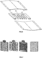
- a cartridge in accordance with the present invention is illustrated in Figure 6 .
- the foils (1F) (thin film material) of the cartridge are preferably slightly larger than the perimeter of the cartridge defined by the perimeter wall (1W) of the web and/or are manufactured in a stretchable material, to allow that the foils can be locally spaced apart from the web wall parts, especially when the liquid flowing through the channel is pressurised at a pressure higher than atmospheric pressure.
- the foils are preferably manufactured in a polymeric material or a metallic material or a metalized polymeric material such as a metallic/polymeric hybrid material having an oxygen transfer of maximally 4 cc/metre/day/bar @20°C, preferably maximally 1cc/metre/day/bar @20°C and most preferably maximally 0,05 cc/metre/day/bar @20°C.
- a suitable material is aluminium, preferably an aluminium foil with a thickness of of 80 ⁇ m or less.
- the web material is preferably either a polymeric material (preferably a polyolefin such as polyethylene, polypropylene, etc.) or a metallic material (preferably aluminium) or a metallic/polymeric hybrid material such as a metal coated polymeric material, with the perimeter wall providing a minimum stiffness to the cartridge.
- the foils can be fixed to the perimeter wall and, if desired, at some distinct points or sections to the web wall parts by welding, brazing or glueing.
- the web wall parts are preferably made as thin as possible to limit the area of the cartridge occupied by web material and hence to maximise the contact area of liquid to be cooled with the foils of the cartridge. Since welding, brazing or glueing of the foils to the web wall parts is optional, the thickness of the web wall parts can be limited, preferably to a thickness of 2 mm or less, preferably 1 mm or less.
- the foils may comprise a metallic, preferably aluminum layer of at least 30 ⁇ m, preferably at least 40 ⁇ m and a polymeric, preferably polyethylene layer having a thickness preferably in a range of 10 ⁇ m to 20 ⁇ m.
- the metallic layer serves preferably provides for the barrier properties and the heat conductive properties of the foils, whereas the polymeric layer allows the foils to be welded to the web material.
- the non-continuous fixation of the foils to the web wall parts provides two important advantages to the cooling cartridge.
- First, is allows for the formation of short-cuts when a pressurized fluid flows through the channel as the foils are spaced from the web wall parts and liquid flows from one section of the channel to another, thereby inducing a turbulent flow in the channel which increases cooling efficiency.
- Second, the absence of a continuous fixation allows for maximise the contact area of liquid to be cooled with the foils of the cartridge again improving cooling efficiency.
- baffles or turbulence inducing elements can be provided in the channel. As illustrated in figure 7 , such turbulence inducing elements (IT) can be made in one piece with the web.
- turbulence inducing elements IT
- the web of material is executed as a mesh having the function of both the web of material (defining the non-rectilinear trajectory of the channel or pathway) and of the baffles.
- the wall parts are more difficult to define, one can define contact zones between the foils and the mesh of material, which contact zones are places where the foils contact the web or mesh of material in the inner area of the cooling cartridge when the pressure reigning in the inner area equals ambient pressure.
- the perimeter wall of the web is defined by four edges, including a first pair of edges which are substantially parallel to one another and a second pair of edges which are substantially parallel to one another and are preferably normal to the first pair of edges, thus defining a rectangle or square.
- the upstream dispensing tube section is permanently coupled to the channel inlet and, similarly, the downstream dispensing tube section is permanently coupled to the channel outlet of the cartridge.
- both upstream and downstream dispensing tube sections are reversibly coupled to the cooling cartridge.
- a cartridge is provided with channel inlet and channel outlet protruding from the perimeter wall.
- the inlet channel is reversibly engaged and coupled to the distal end of the upstream dispensing tube section and, similarly the channel outlet (1o) is reversibly coupled to the proximal end of the downstream dispensing tube section. It can be very advantageous when using kegs provided with an upstream dispensing tube section permanently coupled to said keg, as sometimes available on the market.
- the first surface and second surface of the first and second cooling plates can be varied. This ensures a good contact between the channel (1C) and the cooling plates (2P) so that the heat transfer from the beverage to the cooling plates is optimized.
- the first and second cooling plates are each coupled to resilient means (2F) such as to apply a pressure thereon which tends to decrease the distance separating the first surface and second surface of the first and second cooling plates.
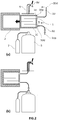
- the two cooling plates are separated from one another by a loading distance, d0, greater than a thickness of the cartridge and forming an insertion slot (2S).
- a cartridge (1) can be inserted into said slot as shown in Figure 4(b) .
- the channel (1C) is generally deflated as the dispensing channel is not yet pressurized at this stage.
- the cartridge channel is inflated (i.e., the foils move apart) and filled with liquid.
- the cold plates are then allowed to yield to the pressure of the resilient means and the first and second surfaces get closer to one another until they reach a cooling distance, dc, at which they contact the thin films of the cartridge forming the tortuous channel (1C).
- the first and second surfaces may comprise a structure mating the surface of the tortuous channel so as to further increase the contact area between the channel and the cooling plates.
- the flexible channel deflates and the first and second surfaces keep contact with the cartridge foils by getting closer to one another following the volume variations of the flexible channel.
- the pressure may decrease when the keg is empty or, in some cases, the keg is not constantly pressurized, but only upon dispensing.
- the advantage of the cooling plates keeping contact with the channel regardless of the volume of the channel is advantageous in that after each dispensing or after a keg got empty; the liquid remaining in the dispensing tube is at least partially pressed out from the channel towards the downstream dispensing tube section to the tapping valve, thus emptying a substantial part of the dispensing tube from any remaining liquid.
- the cooling plates are positioned at a fixed distance from one another and the cartridge is inserted in the slot defined by the distance between the cooling plates with the channel non-pressurised.
- the cartridge channel is inflated (i.e., the foils move apart) and are pressed against the cooling plates.
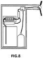
- a cooling unit (2) as defined in the present invention allows dispensing cooled beverages without any chamber for storing one or more containers, be it refrigerated or not.
- a chamber (11) can of course be used to store one or more kegs (5) coupled to a source of pressurized gas (7), but said chamber needs not be refrigerated.
- the cooling unit can be fixed to a wall of said chamber, which comprises means for passing the downstream dispensing tube section from the inside to the outside of the chamber, to a tapping column and a tapping valve.
- FIG. 1(c) illustrates a cooling unit as defined in the present invention in a typical home appliance setup. As discussed above, a cartridge can be very cheap and cooling becomes very easy and economical with the present invention.
- FIG. 7 illustrates a three alternatives of a cooling unit (2) as defined in the present invention in a dispensing apparatus suited for dispensing a beverage starting from a concentrated beverage component, such as a concentrated beer or cider, a diluent and potentially, a source of compressed gas (eg. carbon dioxide, nitrogen or a mixture of both).
- a concentrated beverage component such as a concentrated beer or cider
- a diluent such as a concentrated beer or cider
- a source of compressed gas eg. carbon dioxide, nitrogen or a mixture of both.
- the cooling unit is positioned in a dispense line section connecting a keg or reservoir (10R) with diluent (eg. water or a neutral beer base) with a carbonation unit (10C) as carbonation of the diluent can be performed more efficiently at sub room temperature.
- diluent eg. water or a neutral beer base
- the carbonation unit is preferably positioned downstream a mixing unit (10M) wherein a concentrated beverage component is mixed with the pre-carbonated diluent.
- the cooling unit can be positioned in any other of the dispense line sections, however, it is preferred to cool the diluent or final beverage as the diluent represents the largest volume fraction of the final beverage. Positioning the cooling unit in a dispense line section of the diluent downstream the mixing unit is also advantageous when the diluent is water, for the reason that water is less prone to biological spoilage than the mixed beverage, especially in the case of beer.
- a beverage dispensing apparatus comprising a container/keg/reservoir containing a beverage or beverage component, and further comprising:
- the cartridge is inserted in the insertion slot (2S) of the cooling unit (2).
- a continuous dispensing tube runs from the upstream proximal end (3Up) in fluid communication with the interior of the container to the downstream distal end (3Dd) coupled to the tapping valve and opening to the ambient atmosphere.
- the beverage being dispensed is cooled as it flows through the tortuous channel of the cartridge by exchanging heat with the first and second surfaces of the first and second cooling plates in intimate thermal contact with the thin walls of the channel. A cold or chilled beverage can thus be served without having to cool the whole content of the container.
- a beverage dispensing appliance may comprise more than one cooling units according to the present invention, the different cooling units cooperating with a single dispense line between a beverage or beverage component reservoir and a tap valve or cooperating with multiple dispense lines each coupling a beverage reservoir or beverage component reservoir with a dedicated beverage tap, allowing dispensing more than one beverage from the appliance, whereby each beverage is dispensed through a different dispense line and each of the dispense lines cooperate with a dedicated cooling unit (as such allowing dispensing the different beverages each at its own preferred temperature).
Landscapes
- Engineering & Computer Science (AREA)
- Physics & Mathematics (AREA)
- Thermal Sciences (AREA)
- Mechanical Engineering (AREA)
- General Engineering & Computer Science (AREA)
- Chemical & Material Sciences (AREA)
- Combustion & Propulsion (AREA)
- Devices For Dispensing Beverages (AREA)
- Heat-Exchange Devices With Radiators And Conduit Assemblies (AREA)
- Automatic Analysis And Handling Materials Therefor (AREA)
- Thermotherapy And Cooling Therapy Devices (AREA)
- Separation Using Semi-Permeable Membranes (AREA)
Priority Applications (15)
| Application Number | Priority Date | Filing Date | Title |
|---|---|---|---|
| EP16201501.0A EP3330219A1 (en) | 2016-11-30 | 2016-11-30 | Dispensing apparatus provided with a cooling unit |
| RU2019115805A RU2746611C2 (ru) | 2016-11-30 | 2017-11-29 | Выдачное устройство, снабженное охлаждающим блоком |
| KR1020197018331A KR102506578B1 (ko) | 2016-11-30 | 2017-11-29 | 냉각 유닛을 포함하는 분배 장치 |
| BR112019011088-7A BR112019011088B1 (pt) | 2016-11-30 | 2017-11-29 | Aparelho de dispensação dotado de uma unidade de resfriame |
| ES17811894T ES2866353T3 (es) | 2016-11-30 | 2017-11-29 | Aparato dispensador provisto de una unidad de enfriamiento |
| EP17811894.9A EP3548422B1 (en) | 2016-11-30 | 2017-11-29 | Dispensing apparatus provided with a cooling unit |
| BE2017/5866A BE1025843B1 (nl) | 2016-11-30 | 2017-11-29 | Afgifte-inrichting die wordt geleverd met een koeleenheid |
| AU2017368284A AU2017368284A1 (en) | 2016-11-30 | 2017-11-29 | Dispensing apparatus provided with a cooling unit |
| US16/465,129 US11008205B2 (en) | 2016-11-30 | 2017-11-29 | Dispensing apparatus provided with a cooling unit |
| MX2019006229A MX2019006229A (es) | 2016-11-30 | 2017-11-29 | Aparato dispensador proporcionado con una unidad de enfriamiento. |
| PCT/EP2017/080778 WO2018099947A1 (en) | 2016-11-30 | 2017-11-29 | Dispensing apparatus provided with a cooling unit |
| DK17811894.9T DK3548422T3 (da) | 2016-11-30 | 2017-11-29 | Aftapningsanordning forsynet med en køleenhed |
| CA3045368A CA3045368A1 (en) | 2016-11-30 | 2017-11-29 | Dispensing apparatus provided with a cooling unit |
| JP2019528669A JP2019536702A (ja) | 2016-11-30 | 2017-11-29 | 冷却ユニットを備えた分配装置 |
| ARP170103347A AR110285A1 (es) | 2016-11-30 | 2017-11-30 | Aparato de dispendio provisto con una unidad de enfriamiento |
Applications Claiming Priority (1)
| Application Number | Priority Date | Filing Date | Title |
|---|---|---|---|
| EP16201501.0A EP3330219A1 (en) | 2016-11-30 | 2016-11-30 | Dispensing apparatus provided with a cooling unit |
Publications (1)
| Publication Number | Publication Date |
|---|---|
| EP3330219A1 true EP3330219A1 (en) | 2018-06-06 |
Family
ID=57460372
Family Applications (2)
| Application Number | Title | Priority Date | Filing Date |
|---|---|---|---|
| EP16201501.0A Ceased EP3330219A1 (en) | 2016-11-30 | 2016-11-30 | Dispensing apparatus provided with a cooling unit |
| EP17811894.9A Active EP3548422B1 (en) | 2016-11-30 | 2017-11-29 | Dispensing apparatus provided with a cooling unit |
Family Applications After (1)
| Application Number | Title | Priority Date | Filing Date |
|---|---|---|---|
| EP17811894.9A Active EP3548422B1 (en) | 2016-11-30 | 2017-11-29 | Dispensing apparatus provided with a cooling unit |
Country Status (13)
| Country | Link |
|---|---|
| US (1) | US11008205B2 (es) |
| EP (2) | EP3330219A1 (es) |
| JP (1) | JP2019536702A (es) |
| KR (1) | KR102506578B1 (es) |
| AR (1) | AR110285A1 (es) |
| AU (1) | AU2017368284A1 (es) |
| BE (1) | BE1025843B1 (es) |
| CA (1) | CA3045368A1 (es) |
| DK (1) | DK3548422T3 (es) |
| ES (1) | ES2866353T3 (es) |
| MX (1) | MX2019006229A (es) |
| RU (1) | RU2746611C2 (es) |
| WO (1) | WO2018099947A1 (es) |
Families Citing this family (2)
| Publication number | Priority date | Publication date | Assignee | Title |
|---|---|---|---|---|
| US11034569B2 (en) | 2018-02-14 | 2021-06-15 | Taphandles Llc | Cooled beverage dispensing systems and associated devices |
| US11608259B2 (en) * | 2018-08-27 | 2023-03-21 | LNJ Group, LLC | Beverage dispensing machine and pouch for use with beverage dispensing machine |
Citations (13)
| Publication number | Priority date | Publication date | Assignee | Title |
|---|---|---|---|---|
| DE3446383A1 (de) * | 1983-12-23 | 1985-07-11 | Matsushita Electric Works, Ltd., Kadoma, Osaka | Waermetauschermatte und verfahren zu ihrer herstellung |
| WO1987007361A1 (en) | 1984-05-07 | 1987-12-03 | Vapor Corporation | Peltier thermoelectric element mounting |
| US5634343A (en) | 1994-01-24 | 1997-06-03 | Alko Group, Ltd. | Beverage cooling dispenser |
| JP2002046799A (ja) | 2000-08-02 | 2002-02-12 | Namco Ltd | 冷却機能を備えた家庭用ビールサーバー |
| EP1188995A1 (fr) | 2000-09-19 | 2002-03-20 | Thierry Ancel | Dispositif de refroidissement ou de réchauffement d'un récipient de liquide alimentaire |
| US6658859B2 (en) | 2001-11-26 | 2003-12-09 | Vin Valet, Inc. | Cooling system for wine or champagne preservation and dispensing apparatus |
| WO2004051163A2 (en) | 2002-11-29 | 2004-06-17 | Interbrew S.A. | Alcoholic beverage dispensing apparatus |
| EP1642863A1 (en) | 2004-09-29 | 2006-04-05 | CELLI S.p.A. | A wine bottle storage and multiple dispensing apparatus |
| DE102006005381A1 (de) | 2005-12-31 | 2006-07-20 | Glen Dimplex Deutschland Gmbh | Getränkezapfgerät |
| WO2007076584A2 (en) | 2006-01-03 | 2007-07-12 | Dirk Daluwein | An automatic home multi beer dispensing apparatus |
| EP2103565A1 (fr) | 2008-03-20 | 2009-09-23 | Seb S.A. | Appareil de distribution de boisson muni d'un élément caloporteur |
| WO2010064191A1 (en) | 2008-12-02 | 2010-06-10 | Koninklijke Philips Electronics N.V. | A domestic beverage dispensing device having cooling means |
| WO2013013059A1 (en) * | 2011-07-20 | 2013-01-24 | Scr Inc. | Athletic cooling and heating systems, devices and methods |
Family Cites Families (13)
| Publication number | Priority date | Publication date | Assignee | Title |
|---|---|---|---|---|
| US4829771A (en) * | 1988-03-24 | 1989-05-16 | Koslow Technologies Corporation | Thermoelectric cooling device |
| US4901887A (en) * | 1988-08-08 | 1990-02-20 | Burton John W | Beverage dispensing system |
| JP2002128197A (ja) * | 2000-10-20 | 2002-05-09 | Fuji Electric Co Ltd | 飲料ディスペンサ |
| US6871015B2 (en) * | 2001-12-21 | 2005-03-22 | Nestec S.A. | Compartmentalized dispensing device and method for dispensing a flowable product therefrom |
| US20030188540A1 (en) * | 2002-04-03 | 2003-10-09 | John Van Winkle | Cooling system for a beverage dispenser |
| JP2004060986A (ja) * | 2002-07-29 | 2004-02-26 | Ube Ind Ltd | フレキシブル熱交換器及びその製造方法 |
| IT1396527B1 (it) * | 2008-09-24 | 2012-12-14 | Saeco Ipr Ltd | "macchina da caffe' con sistema per la produzione di caffe' freddo" |
| GB2491623A (en) * | 2011-06-09 | 2012-12-12 | Alberto Martinez Albalat | Multilayer fluid heat exchanger comprising plastic and metal layers |
| JP2015067326A (ja) * | 2013-09-30 | 2015-04-13 | 富士電機株式会社 | フローズン飲料ディスペンサ |
| US20160060089A1 (en) * | 2014-08-27 | 2016-03-03 | Armand R. NETTER | Fluid dispenser |
| WO2017075584A1 (en) * | 2015-10-30 | 2017-05-04 | Lvd Acquisition, Llc | Thermoelectric cooling tank system and methods |
| EP3244157A1 (en) * | 2016-05-13 | 2017-11-15 | Anheuser-Busch InBev S.A. | Dispensing appliance provided with a disposable cooling cartridge |
| KR102515331B1 (ko) * | 2016-10-13 | 2023-03-29 | 엘지전자 주식회사 | 냉수 생성 장치 |
-
2016
- 2016-11-30 EP EP16201501.0A patent/EP3330219A1/en not_active Ceased
-
2017
- 2017-11-29 US US16/465,129 patent/US11008205B2/en active Active
- 2017-11-29 BE BE2017/5866A patent/BE1025843B1/nl active IP Right Grant
- 2017-11-29 MX MX2019006229A patent/MX2019006229A/es unknown
- 2017-11-29 AU AU2017368284A patent/AU2017368284A1/en not_active Abandoned
- 2017-11-29 CA CA3045368A patent/CA3045368A1/en active Pending
- 2017-11-29 EP EP17811894.9A patent/EP3548422B1/en active Active
- 2017-11-29 KR KR1020197018331A patent/KR102506578B1/ko active IP Right Grant
- 2017-11-29 JP JP2019528669A patent/JP2019536702A/ja active Pending
- 2017-11-29 RU RU2019115805A patent/RU2746611C2/ru active
- 2017-11-29 DK DK17811894.9T patent/DK3548422T3/da active
- 2017-11-29 WO PCT/EP2017/080778 patent/WO2018099947A1/en active Application Filing
- 2017-11-29 ES ES17811894T patent/ES2866353T3/es active Active
- 2017-11-30 AR ARP170103347A patent/AR110285A1/es active IP Right Grant
Patent Citations (13)
| Publication number | Priority date | Publication date | Assignee | Title |
|---|---|---|---|---|
| DE3446383A1 (de) * | 1983-12-23 | 1985-07-11 | Matsushita Electric Works, Ltd., Kadoma, Osaka | Waermetauschermatte und verfahren zu ihrer herstellung |
| WO1987007361A1 (en) | 1984-05-07 | 1987-12-03 | Vapor Corporation | Peltier thermoelectric element mounting |
| US5634343A (en) | 1994-01-24 | 1997-06-03 | Alko Group, Ltd. | Beverage cooling dispenser |
| JP2002046799A (ja) | 2000-08-02 | 2002-02-12 | Namco Ltd | 冷却機能を備えた家庭用ビールサーバー |
| EP1188995A1 (fr) | 2000-09-19 | 2002-03-20 | Thierry Ancel | Dispositif de refroidissement ou de réchauffement d'un récipient de liquide alimentaire |
| US6658859B2 (en) | 2001-11-26 | 2003-12-09 | Vin Valet, Inc. | Cooling system for wine or champagne preservation and dispensing apparatus |
| WO2004051163A2 (en) | 2002-11-29 | 2004-06-17 | Interbrew S.A. | Alcoholic beverage dispensing apparatus |
| EP1642863A1 (en) | 2004-09-29 | 2006-04-05 | CELLI S.p.A. | A wine bottle storage and multiple dispensing apparatus |
| DE102006005381A1 (de) | 2005-12-31 | 2006-07-20 | Glen Dimplex Deutschland Gmbh | Getränkezapfgerät |
| WO2007076584A2 (en) | 2006-01-03 | 2007-07-12 | Dirk Daluwein | An automatic home multi beer dispensing apparatus |
| EP2103565A1 (fr) | 2008-03-20 | 2009-09-23 | Seb S.A. | Appareil de distribution de boisson muni d'un élément caloporteur |
| WO2010064191A1 (en) | 2008-12-02 | 2010-06-10 | Koninklijke Philips Electronics N.V. | A domestic beverage dispensing device having cooling means |
| WO2013013059A1 (en) * | 2011-07-20 | 2013-01-24 | Scr Inc. | Athletic cooling and heating systems, devices and methods |
Also Published As
| Publication number | Publication date |
|---|---|
| KR20190108562A (ko) | 2019-09-24 |
| RU2019115805A3 (es) | 2021-02-24 |
| WO2018099947A1 (en) | 2018-06-07 |
| EP3548422A1 (en) | 2019-10-09 |
| KR102506578B1 (ko) | 2023-03-06 |
| BE1025843B1 (nl) | 2019-08-14 |
| DK3548422T3 (da) | 2021-04-06 |
| RU2746611C2 (ru) | 2021-04-16 |
| US20190322517A1 (en) | 2019-10-24 |
| EP3548422B1 (en) | 2020-12-30 |
| MX2019006229A (es) | 2019-07-10 |
| BE1025843A1 (nl) | 2019-07-23 |
| BR112019011088A2 (pt) | 2019-10-01 |
| JP2019536702A (ja) | 2019-12-19 |
| AU2017368284A1 (en) | 2019-06-06 |
| RU2019115805A (ru) | 2021-01-11 |
| AR110285A1 (es) | 2019-03-13 |
| US11008205B2 (en) | 2021-05-18 |
| ES2866353T3 (es) | 2021-10-19 |
| CA3045368A1 (en) | 2018-06-07 |
Similar Documents
| Publication | Publication Date | Title |
|---|---|---|
| EP3455572B1 (en) | Dispensing appliance provided with a disposable cooling cartridge | |
| EP3548422B1 (en) | Dispensing apparatus provided with a cooling unit | |
| US11981556B2 (en) | Cooled beverage dispensing systems and associated devices | |
| US20110006078A1 (en) | Beverage device and tank thereof | |
| CA2482264A1 (en) | Method and apparatus for chilling draught beverages | |
| EP3548814B1 (en) | Dispensing apparatus provided with a cooling unit | |
| US20160023882A1 (en) | Beverage system ice maker and ice and water reservoir | |
| BR112019011088B1 (pt) | Aparelho de dispensação dotado de uma unidade de resfriame | |
| EP1862427A1 (en) | A beverage dispense system | |
| CA2486630A1 (en) | Method and apparatus for chilling draught beverages in a trunk line | |
| CA2612800A1 (en) | Beverage dispenser cooling system |
Legal Events
| Date | Code | Title | Description |
|---|---|---|---|
| PUAI | Public reference made under article 153(3) epc to a published international application that has entered the european phase |
Free format text: ORIGINAL CODE: 0009012 |
|
| STAA | Information on the status of an ep patent application or granted ep patent |
Free format text: STATUS: THE APPLICATION HAS BEEN PUBLISHED |
|
| AK | Designated contracting states |
Kind code of ref document: A1 Designated state(s): AL AT BE BG CH CY CZ DE DK EE ES FI FR GB GR HR HU IE IS IT LI LT LU LV MC MK MT NL NO PL PT RO RS SE SI SK SM TR |
|
| AX | Request for extension of the european patent |
Extension state: BA ME |
|
| STAA | Information on the status of an ep patent application or granted ep patent |
Free format text: STATUS: THE APPLICATION HAS BEEN REFUSED |
|
| STAA | Information on the status of an ep patent application or granted ep patent |
Free format text: STATUS: THE APPLICATION HAS BEEN REFUSED |
|
| 18R | Application refused |
Effective date: 20180629 |