EP3330196A1 - Device for receiving objects - Google Patents
Device for receiving objects Download PDFInfo
- Publication number
- EP3330196A1 EP3330196A1 EP16201630.7A EP16201630A EP3330196A1 EP 3330196 A1 EP3330196 A1 EP 3330196A1 EP 16201630 A EP16201630 A EP 16201630A EP 3330196 A1 EP3330196 A1 EP 3330196A1
- Authority
- EP
- European Patent Office
- Prior art keywords
- connecting body
- square
- tangent
- base
- receiving
- Prior art date
- Legal status (The legal status is an assumption and is not a legal conclusion. Google has not performed a legal analysis and makes no representation as to the accuracy of the status listed.)
- Granted
Links
- 239000000463 material Substances 0.000 claims description 3
- 239000007769 metal material Substances 0.000 claims description 3
- 230000007704 transition Effects 0.000 claims description 3
- 238000001746 injection moulding Methods 0.000 claims description 2
- 238000012545 processing Methods 0.000 description 4
- 230000007797 corrosion Effects 0.000 description 3
- 238000005260 corrosion Methods 0.000 description 3
- 238000011161 development Methods 0.000 description 3
- 230000018109 developmental process Effects 0.000 description 3
- 238000003860 storage Methods 0.000 description 3
- 238000004140 cleaning Methods 0.000 description 2
- 230000001419 dependent effect Effects 0.000 description 1
- 238000003487 electrochemical reaction Methods 0.000 description 1
- 239000012530 fluid Substances 0.000 description 1
- 239000007788 liquid Substances 0.000 description 1
- 238000003754 machining Methods 0.000 description 1
- 238000004519 manufacturing process Methods 0.000 description 1
- 238000000034 method Methods 0.000 description 1
Images


Classifications
-
- B—PERFORMING OPERATIONS; TRANSPORTING
- B65—CONVEYING; PACKING; STORING; HANDLING THIN OR FILAMENTARY MATERIAL
- B65D—CONTAINERS FOR STORAGE OR TRANSPORT OF ARTICLES OR MATERIALS, e.g. BAGS, BARRELS, BOTTLES, BOXES, CANS, CARTONS, CRATES, DRUMS, JARS, TANKS, HOPPERS, FORWARDING CONTAINERS; ACCESSORIES, CLOSURES, OR FITTINGS THEREFOR; PACKAGING ELEMENTS; PACKAGES
- B65D19/00—Pallets or like platforms, with or without side walls, for supporting loads to be lifted or lowered
- B65D19/38—Details or accessories
- B65D19/44—Elements or devices for locating articles on platforms
-
- B—PERFORMING OPERATIONS; TRANSPORTING
- B65—CONVEYING; PACKING; STORING; HANDLING THIN OR FILAMENTARY MATERIAL
- B65D—CONTAINERS FOR STORAGE OR TRANSPORT OF ARTICLES OR MATERIALS, e.g. BAGS, BARRELS, BOTTLES, BOXES, CANS, CARTONS, CRATES, DRUMS, JARS, TANKS, HOPPERS, FORWARDING CONTAINERS; ACCESSORIES, CLOSURES, OR FITTINGS THEREFOR; PACKAGING ELEMENTS; PACKAGES
- B65D2519/00—Pallets or like platforms, with or without side walls, for supporting loads to be lifted or lowered
- B65D2519/00004—Details relating to pallets
- B65D2519/00009—Materials
- B65D2519/00014—Materials for the load supporting surface
- B65D2519/00024—Metal
-
- B—PERFORMING OPERATIONS; TRANSPORTING
- B65—CONVEYING; PACKING; STORING; HANDLING THIN OR FILAMENTARY MATERIAL
- B65D—CONTAINERS FOR STORAGE OR TRANSPORT OF ARTICLES OR MATERIALS, e.g. BAGS, BARRELS, BOTTLES, BOXES, CANS, CARTONS, CRATES, DRUMS, JARS, TANKS, HOPPERS, FORWARDING CONTAINERS; ACCESSORIES, CLOSURES, OR FITTINGS THEREFOR; PACKAGING ELEMENTS; PACKAGES
- B65D2519/00—Pallets or like platforms, with or without side walls, for supporting loads to be lifted or lowered
- B65D2519/00004—Details relating to pallets
- B65D2519/00009—Materials
- B65D2519/00049—Materials for the base surface
- B65D2519/00059—Metal
-
- B—PERFORMING OPERATIONS; TRANSPORTING
- B65—CONVEYING; PACKING; STORING; HANDLING THIN OR FILAMENTARY MATERIAL
- B65D—CONTAINERS FOR STORAGE OR TRANSPORT OF ARTICLES OR MATERIALS, e.g. BAGS, BARRELS, BOTTLES, BOXES, CANS, CARTONS, CRATES, DRUMS, JARS, TANKS, HOPPERS, FORWARDING CONTAINERS; ACCESSORIES, CLOSURES, OR FITTINGS THEREFOR; PACKAGING ELEMENTS; PACKAGES
- B65D2519/00—Pallets or like platforms, with or without side walls, for supporting loads to be lifted or lowered
- B65D2519/00004—Details relating to pallets
- B65D2519/00258—Overall construction
- B65D2519/00263—Overall construction of the pallet
- B65D2519/00273—Overall construction of the pallet made of more than one piece
-
- B—PERFORMING OPERATIONS; TRANSPORTING
- B65—CONVEYING; PACKING; STORING; HANDLING THIN OR FILAMENTARY MATERIAL
- B65D—CONTAINERS FOR STORAGE OR TRANSPORT OF ARTICLES OR MATERIALS, e.g. BAGS, BARRELS, BOTTLES, BOXES, CANS, CARTONS, CRATES, DRUMS, JARS, TANKS, HOPPERS, FORWARDING CONTAINERS; ACCESSORIES, CLOSURES, OR FITTINGS THEREFOR; PACKAGING ELEMENTS; PACKAGES
- B65D2519/00—Pallets or like platforms, with or without side walls, for supporting loads to be lifted or lowered
- B65D2519/00004—Details relating to pallets
- B65D2519/00258—Overall construction
- B65D2519/00283—Overall construction of the load supporting surface
- B65D2519/00293—Overall construction of the load supporting surface made of more than one piece
-
- B—PERFORMING OPERATIONS; TRANSPORTING
- B65—CONVEYING; PACKING; STORING; HANDLING THIN OR FILAMENTARY MATERIAL
- B65D—CONTAINERS FOR STORAGE OR TRANSPORT OF ARTICLES OR MATERIALS, e.g. BAGS, BARRELS, BOTTLES, BOXES, CANS, CARTONS, CRATES, DRUMS, JARS, TANKS, HOPPERS, FORWARDING CONTAINERS; ACCESSORIES, CLOSURES, OR FITTINGS THEREFOR; PACKAGING ELEMENTS; PACKAGES
- B65D2519/00—Pallets or like platforms, with or without side walls, for supporting loads to be lifted or lowered
- B65D2519/00004—Details relating to pallets
- B65D2519/00258—Overall construction
- B65D2519/00283—Overall construction of the load supporting surface
- B65D2519/00298—Overall construction of the load supporting surface skeleton type
-
- B—PERFORMING OPERATIONS; TRANSPORTING
- B65—CONVEYING; PACKING; STORING; HANDLING THIN OR FILAMENTARY MATERIAL
- B65D—CONTAINERS FOR STORAGE OR TRANSPORT OF ARTICLES OR MATERIALS, e.g. BAGS, BARRELS, BOTTLES, BOXES, CANS, CARTONS, CRATES, DRUMS, JARS, TANKS, HOPPERS, FORWARDING CONTAINERS; ACCESSORIES, CLOSURES, OR FITTINGS THEREFOR; PACKAGING ELEMENTS; PACKAGES
- B65D2519/00—Pallets or like platforms, with or without side walls, for supporting loads to be lifted or lowered
- B65D2519/00004—Details relating to pallets
- B65D2519/00258—Overall construction
- B65D2519/00313—Overall construction of the base surface
- B65D2519/00323—Overall construction of the base surface made of more than one piece
-
- B—PERFORMING OPERATIONS; TRANSPORTING
- B65—CONVEYING; PACKING; STORING; HANDLING THIN OR FILAMENTARY MATERIAL
- B65D—CONTAINERS FOR STORAGE OR TRANSPORT OF ARTICLES OR MATERIALS, e.g. BAGS, BARRELS, BOTTLES, BOXES, CANS, CARTONS, CRATES, DRUMS, JARS, TANKS, HOPPERS, FORWARDING CONTAINERS; ACCESSORIES, CLOSURES, OR FITTINGS THEREFOR; PACKAGING ELEMENTS; PACKAGES
- B65D2519/00—Pallets or like platforms, with or without side walls, for supporting loads to be lifted or lowered
- B65D2519/00004—Details relating to pallets
- B65D2519/00258—Overall construction
- B65D2519/00313—Overall construction of the base surface
- B65D2519/00328—Overall construction of the base surface shape of the contact surface of the base
- B65D2519/00338—Overall construction of the base surface shape of the contact surface of the base contact surface having a discrete foot-like shape
-
- B—PERFORMING OPERATIONS; TRANSPORTING
- B65—CONVEYING; PACKING; STORING; HANDLING THIN OR FILAMENTARY MATERIAL
- B65D—CONTAINERS FOR STORAGE OR TRANSPORT OF ARTICLES OR MATERIALS, e.g. BAGS, BARRELS, BOTTLES, BOXES, CANS, CARTONS, CRATES, DRUMS, JARS, TANKS, HOPPERS, FORWARDING CONTAINERS; ACCESSORIES, CLOSURES, OR FITTINGS THEREFOR; PACKAGING ELEMENTS; PACKAGES
- B65D2519/00—Pallets or like platforms, with or without side walls, for supporting loads to be lifted or lowered
- B65D2519/00004—Details relating to pallets
- B65D2519/00736—Details
- B65D2519/0081—Elements or devices for locating articles
- B65D2519/00815—Elements or devices for locating articles on the pallet
-
- F—MECHANICAL ENGINEERING; LIGHTING; HEATING; WEAPONS; BLASTING
- F16—ENGINEERING ELEMENTS AND UNITS; GENERAL MEASURES FOR PRODUCING AND MAINTAINING EFFECTIVE FUNCTIONING OF MACHINES OR INSTALLATIONS; THERMAL INSULATION IN GENERAL
- F16B—DEVICES FOR FASTENING OR SECURING CONSTRUCTIONAL ELEMENTS OR MACHINE PARTS TOGETHER, e.g. NAILS, BOLTS, CIRCLIPS, CLAMPS, CLIPS OR WEDGES; JOINTS OR JOINTING
- F16B21/00—Means for preventing relative axial movement of a pin, spigot, shaft or the like and a member surrounding it; Stud-and-socket releasable fastenings
- F16B21/02—Releasable fastening devices locking by rotation
Definitions
- the invention relates to a device for receiving objects, such as workpieces or tools, according to the preamble of claim 1 and to a connecting body as part of the device and for use in such a device according to claim 2.
- Such devices are versatile and should keep for transport, storage or processing purposes inserted workpieces reliable and damage-free.
- such devices consist of a plurality of parallel and spaced apart wire strands, which are orthogonal to each other in two different planes and thus form a lattice structure, which is used as a support frame.
- a device is for example the EP 2 860 127 B1 or the DE 10 2012 0205 91 A1 refer to.
- the connecting bodies to be locked to the supporting frame have a holding base on which two radially projecting retaining lugs are formed, by means of which the connecting body can be inserted into the lattice structure and locked by rotation through 90 °.
- the tags and the connecting bodies attached thereto are often fed together with the workpieces to a machining process and the process fluids can drain quickly through the grid structure after processing.
- the grid structure must provide rectangular receiving openings available, in which the connecting body can be used and rotated.
- the spacing between the parallel and spaced wire strands in the lower and upper levels is thus different, typically with the spacing between the strands of wire sized to be greater in the upper level than in the lower, thereby forming the rectangular grid structure.
- the crossing wire strands are firmly connected to each other in the nodes, so that the support frame has a grid structure with high intrinsic stability and the individual rectangular receiving openings are dimensionally stable.
- connection body can not be used with conventional square lattice structures and always custom-made lattice structures with rectangular receiving openings must be provided, since a screwing of the connecting body is feasible only in a rectangular grid structure.
- Such special designs are known to be associated with considerable costs.
- the connecting bodies are intended to be inexpensive to produce in an injection molding process and be mountable in conventional square lattice structures, so that the surface utilization is optimal on a support frame.
- the support base is square in cross section and adapted to the respective mesh size of the receiving opening, that the support base in the respective plane has at least two clamping grooves which extend diametrically and mirror symmetrically over one of the longitudinal edges of the support base, that the respective clamping groove of a rounding radius and a tangent is formed and that the rounding radius transitions within a quarter-pitch circle in the tangent, the connecting body can be inserted into the square receiving opening and locked by a rotation about the pitch circle angle.
- the radius of the radius of curvature corresponds to half the mesh size.
- the wire strands are thus at the turning of the connecting body in the clamping groove approximately selective, so that the connecting body is easily rotatable and is supported from all sides in the receiving opening.
- the rounding radius merges into the tangent at a pitch circle angle of 45 °, so that the connecting body is locked to the support frame after a rotation of 45 °.
- pitch circle dimensions are possible as long as the pitch angle is less than 90 °. Accordingly, angle dimensions of 30 ° or 60 ° are also possible.
- a detent Between the rounding radius and the tangent can be arranged a detent, are bent slightly by the twisting of the connecting body in the receiving opening two opposite strands of wire, so that the detent on the one hand haptic feedback when reaching the end position and on the other hand in the locked state, a rotation forms.
- the clamping grooves may have a V, round or rectangular shape, wherein the width of the grooves is adapted to the respective thickness or diameter of the wire strands.
- the wire strands can be made of a metallic material. It is particularly advantageous if the metallic wire strands are made of a corrosion-resistant material or coated with a corrosion-resistant material.
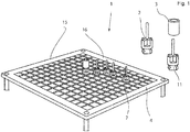
- FIG. 1 a device 1 is shown, by means of which a connecting body 2 is fixed in a position-oriented and rotationally fixed manner as part of the device 1 for receiving objects 3.
- the objects 3 inserted into the connecting body 2, for example workpieces or tools, are intended to be supported by the connecting bodies 2 without damage for transport, cleaning, storage and processing purposes.
- the device 1 comprises a box section 16 which is formed from four frame parts 15 which run perpendicular to one another and which are firmly connected to one another at their respective free ends. These box sections 16 can be used as transport aids or as holding means for workpieces and tools of all kinds.
- a plurality of mutually parallel and objected to each other extending wire strands 7 are arranged, which extend in two different planes 5, 6 and thus form a provided with a square grid structure support frame 4.
- the clear distance between two parallel and spaced wire strands 7 corresponds to the mesh size W, thus consequently the receiving opening 8 has the square dimensions of W * W.
- the wire strands 7 in the planes 5, 6 are arranged equidistant and the wire strands 7 in the two different planes 5, 6 are aligned orthogonal to each other.
- the wire strands 7 are preferably made of a corrosion-resistant metallic material and have a rotationally symmetrical cross-section whose thickness or diameter d 1 or d 2 corresponds.
- the distance I 1 between the support base 11 facing side of the bottom 10 and the upper level 5 corresponds to half the thickness or the diameter d 1 of the wire strand 7 in the upper level 5.
- I 2 the distance between the upper and the lower level 5, 6 which corresponds to the distance between the two wire strands 7 in the upper and lower levels 5, 6, measured from their respective centers.
- the distance between the planes 5 and 6 corresponds to the diameter d 1 or d 2 wire strands 7.
- the connecting body 2 consists essentially of a bottom 7 at the first end side of a support base 11 is worked or molded and on the second end side of a holding and receiving element 12 is aligned with a longitudinal axis 9 of the connecting body 2.
- the longitudinal axis 9 thus extends through the center of the square support base 11th
- the bottom 7 of the connecting body 2 serves on the one hand as a horizontal support for the objects 3 which are held in a spaced manner supported by the connecting body 2 on the support frame 4 and on the other hand serves the support base 11 facing side as a support surface of the connecting body 2 on the wire strands 7 and the support frame 4.
- the base of the support base 11 facing side of the support base 11 is at least as large as the area of the receiving opening 8, so that the bottom 10 of the receiving body 2 when inserted into the receiving opening 8 forms a stop by the vertical position of the connecting body. 2 is specified on the support frame 4.
- the base is circular in shape, wherein the diameter corresponds to at least the mesh width W.
- the support base 11 has a square basic shape with four side edges, which corresponds to the mesh size W minus a tolerance.
- On the support base 11 extend parallel and spaced from the longitudinal axis 9 four longitudinal edges 31, 32, 33, 34.
- the longitudinal edges 31, 32, 33, 34 and the side edges frame the respective side surface, which is part of the lateral surface of the support base and can be rounded for manufacturing reasons or with a chamfer be provided. This rounding or bevel is dimensioned small in relation to a side edge of the retaining base 11.
- the length of the support base 11 parallel to the longitudinal axis 9 corresponds at least to the depth of the receiving opening 8, so that the support base 11 of the connecting body 2, the receiving opening 8 completely engages in the assembled state.
- the length of the holding base 11 preferably corresponds to the sum of the two respective diameters d 1 and d 2 of the wire strands 7.
- FIGS. 4b and 4c can be seen in the two planes 5, 6 clamping grooves 13 incorporated.
- the clamping grooves 13 are each incorporated in the outer circumferential surface 14 of the support base 11 in one of the planes 5, 6 perpendicular to the longitudinal axis 9 and each extend over one of the longitudinal edges 31, 32, 33, 34 of the support base eleventh
- the clamping grooves 13 in the respective plane 5 or 6 are arranged diametrically and mirror-inverted to each other or positioned rotated by 180 ° about the longitudinal axis 9 to each other.
- the arrangement of the clamping grooves 13 in the lower and upper levels 5, 6 is analogous, but the clamping grooves 13 are the two planes 5, 6 rotated against each other by 90 ° about the longitudinal axis 9. Consequently, the clamping grooves 13 extend in the upper plane over the longitudinal edges 31 and 33 and in the lower level 6 over the longitudinal edges 32 and 34.
- a clamping groove thirteenth located on each longitudinal edge 31, 32, 33, 34 of the support base 11, a clamping groove thirteenth
- the radius of the rounding radius R corresponds to half of the mesh width W, ie W / 2, or half of the length of the side edges and whose center is arranged on the longitudinal axis 9.
- the connecting body 2 is thus about the longitudinal axis 9 in the direction of rotation designated by the reference numeral 20 rotatable by 45 °.
- the wire strands 7 at the rounding radius R of the respective clamping groove 13 are approximately selectively. After 45 °, the end position of the connecting body 2 is reached and the tangent T of the clamping groove 13 has long been applied to the respective wire strand 7. A further rotation of the connecting body 2 about the longitudinal axis 9 in the direction of rotation 20 is not possible.
- a latching lug 18 is arranged between the rounding radius R and the tangent T.
- the locking lug 18 is designed such that it protrudes in the clamping groove 13 from the longitudinal axis 9 in the radial direction, so that upon rotation of the connecting body 2, the respective adjacent in the clamping groove 13 wire strands 7 are bent apart and then in a further rotation in to return to their original position.
- the clamping grooves 13 can for this purpose have a rectangular, round, V-shaped, or adapted to the shape of the wire strands 7 geometry.
- FIGS. 5a to 5c a connecting body 2 is shown attached to the four vertically projecting from the bottom 7 holding elements 12, which are distributed uniformly over the circumference.
- the holding elements 12 are parallel and objected to each other and arranged parallel to the longitudinal axis 9 and define an externally accessible space 25 such that the object 3 is accessible only from an opposite end of the bottom 7.
- Two adjacent holding elements 12 are each connected to a support ribs 21 and thus supported against each other.
- On the side facing away from the space 25 of the connecting body 2 7 four evenly distributed over the circumference paragraphs 23 are integrally formed or worked on the bottom and aligned parallel to the bottom 7.
- the longitudinal edges 31, 32, 33, 34 of the square support base 11 are aligned with the support members 12.
- Further possible angles are between 0 ° and .90 ° are possible, preferably 30 °, 60 °, 90 °.
- connecting bodies 2 are mounted correspondingly adjacent to a support frame 4, a further space 25 is enclosed between the connecting bodies 2, in which an object 3 can be held.
- the paragraphs 23 of the connecting body 2 in this case form the horizontal support surface for the object 3 so that it is held at a distance from the wire strands 7 or the support frame 4.
- the objectionable storage of the objects 3 is advantageous in order to avoid electrochemical reactions.
- one or more grooves 24 may be incorporated on the side facing away from the support base 11 of the bottom 7.
- the grooves 24 may also be configured as a through hole, which penetrates parallel to the longitudinal axis 9, the bottom and the support base 11.
Abstract
Vorrichtung (1) zur Aufnahme und zur Arretierung von Gegenständen (3), mit einem nach Art einer Quadrat-Gitterstruktur aufgebauten Traggestell (4), das aus in jeweils einer Ebene (5, 6) parallel und beabstandet zueinander angeordneten Drahtsträngen (7) gebildet ist, durch die mindestens eine quadratische Aufnahmeöffnung (8) geschaffen ist, und mit mindestens einem Verbindungskörper (2) mit einem Boden (10), an dessen einer Stirnseite fluchtend zu einer Längsachse (9) ein Haltesockel (11) vorgesehen ist, der in eine der Aufnahmeöffnungen (8) des Traggestells (4) einsteckbar ist und diese durchgreift und an dessen gegenüberliegenden Stirnseite eine oder mehrere Halte- oder Aufnahmeelemente (12) angebracht sind, durch die die Gegenstände (3) mit dem Verbindungskörper (2) und dem Traggestell (4) fixierbar sind. Der Haltesockel (11) ist im Querschnitt quadratisch und an die jeweilige Maschenweite (W) der Aufnahmeöffnung (8) angepasst, wobei der Haltesockel (11) in der jeweiligen Ebene (5, 6) mindestens zwei Klemmnuten (13) aufweist, die diametral und spiegelsymmetrisch jeweils über eine der Längskanten (31 und 33, 32 und 34) des Haltesockels (11) verlaufen, die jeweilige Klemmnut (13) aus einem Verrundungsradius (R) und einer Tangente (T) gebildet ist, und der Verrundungsradius (R) innerhalb eines Viertelteilkreises in die Tangente (T) übergeht.

Description
Die Erfindung bezieht sich auf eine Vorrichtung zur Aufnahme von Gegenständen, beispielsweise von Werkstücken oder Werkzeugen, nach dem Oberbegriff des Patentanspruches 1 sowie auf einen Verbindungskörper als Bestandteil der Vorrichtung und zur Anwendung in einer solchen nach Patentanspruch 2.The invention relates to a device for receiving objects, such as workpieces or tools, according to the preamble of
Derartige Vorrichtungen sind vielseitig einsetzbar und sollen zu Transport-, Lager- oder Bearbeitungszwecken eingesteckte Werkstücke zuverlässig und beschädigungsfrei halten.Such devices are versatile and should keep for transport, storage or processing purposes inserted workpieces reliable and damage-free.
Üblicherweise bestehen solche Vorrichtungen aus einer Vielzahl von parallel und beabstandet zueinander verlaufenden Drahtsträngen, die in zwei unterschiedlichen Ebenen orthogonal zueinander verlaufen und somit eine Gitterstruktur bilden, die als Traggestell verwendet ist. Eine derartige Vorrichtung ist beispielsweise der
Die Taggestelle und die daran befestigten Verbindungskörper werden oftmals gemeinsam mit den Werkstücken einem Bearbeitungsprozess zugeführt und die Prozess-Flüssigkeiten können durch die Gitterstruktur nach der Bearbeitung schnell abfließen.The tags and the connecting bodies attached thereto are often fed together with the workpieces to a machining process and the process fluids can drain quickly through the grid structure after processing.
Bei solchen Traggestellen hat es sich als nachteilig erwiesen, dass die Gitterstruktur rechteckförmige Aufnahmeöffnungen zur Verfügung stellen muss, in die die Verbindungskörper einsetzbar und verdrehbar sind. Der Abstand zwischen den parallel und beabstandeten Drahtsträngen in der unteren und der oberen Ebene unterschiedlich ist folglich bemessen, wobei typischerweise der Abstand zwischen den Drahtsträngen in der oberen Ebene größer bemessen ist als in der unteren, wodurch die rechteckige Gitterstruktur gebildet ist. Die sich überkreuzenden Drahtstränge sind in den Knotenpunkten fest miteinander verbunden, so dass das Traggestell eine Gitterstruktur mit hoher Eigenstabilität aufweist und die einzelnen reckteckförmigen Aufnahmeöffnungen formstabil sind.In such support frames, it has proven to be disadvantageous that the grid structure must provide rectangular receiving openings available, in which the connecting body can be used and rotated. The spacing between the parallel and spaced wire strands in the lower and upper levels is thus different, typically with the spacing between the strands of wire sized to be greater in the upper level than in the lower, thereby forming the rectangular grid structure. The crossing wire strands are firmly connected to each other in the nodes, so that the support frame has a grid structure with high intrinsic stability and the individual rectangular receiving openings are dimensionally stable.
Nachteilig an diesem Stand der Technik hat sich herausgestellt, dass insbesondere bei rotationssymmetrischen Werkstücken die Lagerdichte aufgrund der rechteckigen Form gering ist.A disadvantage of this prior art has been found that, especially in rotationally symmetrical workpieces, the bearing density is low due to the rectangular shape.
Darüber hinaus hat es sich als nachteilig erweisen, dass die Verbindungskörper nicht mit herkömmlichen quadratischen Gitterstrukturen einsetzbar sind und stets sondergefertigte Gitterstrukturen mit rechteckigen Aufnahmeöffnungen zur Verfügung gestellt werden müssen, da ein Eindrehen der Verbindungskörper ausschließlich bei einer rechteckförmigen Gitterstruktur durchführbar ist. Solche Sonderanfertigungen sind bekanntlich mit erheblichen Kosten verbunden.In addition, it has proven to be disadvantageous that the connection body can not be used with conventional square lattice structures and always custom-made lattice structures with rectangular receiving openings must be provided, since a screwing of the connecting body is feasible only in a rectangular grid structure. Such special designs are known to be associated with considerable costs.
Es ist daher Aufgabe der Erfindung eine Vorrichtung sowie einen Verbindungskörper der eingangs genannten Gattung als Befestigungskörper für Gegenstände in einem Traggestell bereitzustellen, durch die eine zuverlässige dauerhafte, jedoch lösbare Verbindung zwischen dem Verbindungskörper und dem Traggestell vorliegt, deren Befestigung ausschließlich mittels eines vorgegebenen Drehmomentes geschaffen bzw. gelöst werden kann. Die Verbindungskörper sollen dabei in einem Spritzgussverfahren kostengünstig herstellbar sein und in herkömmliche quadratischen Gitterstrukturen montierbar sein, so dass die Flächenausnutzung auf einem Traggestell optimal ist.It is therefore an object of the invention to provide a device and a connecting body of the type mentioned as a fastening body for objects in a support frame through which a reliable permanent, but releasable connection between the connecting body and the support frame is present, the attachment created exclusively by means of a predetermined torque or can be solved. The connecting bodies are intended to be inexpensive to produce in an injection molding process and be mountable in conventional square lattice structures, so that the surface utilization is optimal on a support frame.
Diese Aufgabe ist erfindungsgemäß durch die Merkmale der kennzeichnenden Teile von Patentanspruch 1 bzw. 2 gelöst.This object is achieved by the features of the characterizing parts of
Weitere vorteilhafte Weiterbildungen der Erfindung ergeben sich aus den Unteransprüchen.Further advantageous developments of the invention will become apparent from the dependent claims.
Dadurch, dass der Haltesockel im Querschnitt quadratisch und an die jeweilige Maschenweite der Aufnahmeöffnung angepasst ist, dass der Haltesockel in der jeweiligen Ebene mindestens zwei Klemmnuten aufweist, die diametral und spiegelsymmetrisch jeweils über eine der Längskanten des Haltesockels verlaufen, dass die jeweilige Klemmnut aus einem Verrundungsradius und einer Tangente gebildet ist und dass der Verrundungsradius innerhalb eines Viertelteilkreises in die Tangente übergeht, kann der Verbindungskörper in die quadratische Aufnahmeöffnung eingesetzt werden und durch eine Drehung um den Teilkreiswinkel arretiert werden.Characterized in that the support base is square in cross section and adapted to the respective mesh size of the receiving opening, that the support base in the respective plane has at least two clamping grooves which extend diametrically and mirror symmetrically over one of the longitudinal edges of the support base, that the respective clamping groove of a rounding radius and a tangent is formed and that the rounding radius transitions within a quarter-pitch circle in the tangent, the connecting body can be inserted into the square receiving opening and locked by a rotation about the pitch circle angle.
Darüber hinaus hat es sich als besonders vorteilhaft erwiesen, wenn der Radius des Verrundungsradius der Hälfte der Maschenweite entspricht. Die Drahtstränge liegen somit bei dem Verdrehen des Verbindungskörpers in der Klemmnut annähernd punktuelle an, so dass der Verbindungskörper leichtläufig verdrehbar ist und von allen Seiten in der Aufnahmeöffnung abgestützt ist. Ferner ist es vorteilhaft, wenn der Verrundungsradius nach einem Teilkreiswinkel von 45° in die Tangente übergeht, so dass der Verbindungskörper nach einer Drehung um 45° an dem Traggestell arretiert ist. Weitere Teilkreiswinkel-Maße sind möglich, solange der Teilkreiswinkel kleiner als 90° ist. Demnach sind Winkelmaße von 30° oder 60° auch möglich.In addition, it has proved to be particularly advantageous if the radius of the radius of curvature corresponds to half the mesh size. The wire strands are thus at the turning of the connecting body in the clamping groove approximately selective, so that the connecting body is easily rotatable and is supported from all sides in the receiving opening. Further, it is advantageous if the rounding radius merges into the tangent at a pitch circle angle of 45 °, so that the connecting body is locked to the support frame after a rotation of 45 °. Further pitch circle dimensions are possible as long as the pitch angle is less than 90 °. Accordingly, angle dimensions of 30 ° or 60 ° are also possible.
Zwischen dem Verrundungsradius und der Tangente kann eine Rastnase angeordnet sein, durch die beim Verdrehen des Verbindungskörpers in der Aufnahmeöffnung zwei gegenüberliegende Drahtstränge geringfügig auseinander gebogen werden, so dass die Rastnase einerseits eine haptische Rückmeldung bei dem Erreichen der Endposition gibt und andererseits im eingerasteten Zustand eine Verdrehsicherung bildet.Between the rounding radius and the tangent can be arranged a detent, are bent slightly by the twisting of the connecting body in the receiving opening two opposite strands of wire, so that the detent on the one hand haptic feedback when reaching the end position and on the other hand in the locked state, a rotation forms.
Die Klemmnuten können eine V-, Rund- oder Reckeckform aufweisen, wobei die Breite der Nuten an den jeweiligen Dicke bzw. Durchmesser der Drahtstränge angepasst ist. Die Drahtstränge können aus einem metallischen Werkstoff hergestellt sein. Besonders vorteilhaft ist dabei, wenn die metallischen Drahtstränge aus einem korrosionsbeständigen Werkstoff hergestellt sind oder mit einem korrosionsbeständigen Werkstoff beschichtet sind.The clamping grooves may have a V, round or rectangular shape, wherein the width of the grooves is adapted to the respective thickness or diameter of the wire strands. The wire strands can be made of a metallic material. It is particularly advantageous if the metallic wire strands are made of a corrosion-resistant material or coated with a corrosion-resistant material.
In der Zeichnung ist ein erfindungsgemäßes Ausführungsbeispiel dargestellt sowie eine Weiterbildung dessen, das nachstehend näher erläutert ist. Im Einzelnen zeigt:
Figur 1- eine Vorrichtung, bestehend aus einer Vielzahl von parallel und beabstandet zueinander verlaufenden Drahtsträngen, die jeweils in zwei unterschiedlichen Ebenen angeordnet sind und gemeinsam eine Vielzahl von quadratischen Aufnahmeöffnungen zur Bildung eines Traggestelles aufweisen und aus mehreren Verbindungskörpern und einem daran an geformten Haltesockel, der in eine der Aufnahmeöffnungen einsteckbar ist, in perspektivischer Darstellung,
Figur 2- einen vergrößerten Ausschnitt der Vorrichtung gemäß
Figur 1 Figur 3- einen Verbindungskörper, gemäß
Figur 12 , in Seitenansicht, - Figur 4a
- den Verbindungskörper gemäß
Figur 3 - Figur 4b
- den Verbindungskörper gemäß
Figur 4a entlang der Schnittlinie IVb-IVb, - Figur 4c
- den Verbindungskörper gemäß
Figur 3 - Figur 4d
- den Verbindungskörper gemäß
Figur 3 - Figur 5a
- eine Weiterbildung des Verbindungskörpers gemäß
Figur 1 - Figur 5b
- eine Seitenansicht des Verbindungskörpers gemäß
Figur 5a und - Figur 5c
- eine Draufsicht des Verbindungskörpers gemäß
Figur 5a .
- FIG. 1
- a device consisting of a plurality of parallel and spaced apart wire strands, each arranged in two different planes and collectively having a plurality of square receiving openings to form a support frame and a plurality of connecting bodies and a thereto formed support base, which in one of Receiving openings can be inserted, in perspective,
- FIG. 2
- an enlarged section of the device according to
FIG. 1 , with an inserted connecting body, - FIG. 3
- a connecting body, according to
FIG. 1 or2 , in side view, - FIG. 4a
- according to the connecting body
FIG. 3 along the section line IVa-IVa, - FIG. 4b
- according to the connecting body
FIG. 4a along the section line IVb-IVb, - Figure 4c
- according to the connecting body
FIG. 3 along the section line IVc-IVc, - FIG. 4d
- according to the connecting body
FIG. 3 along the section line IVd-IVd, - FIG. 5a
- a development of the connecting body according to
FIG. 1 with four parallel and spaced retaining elements, which form a space for receiving an object, in perspective view, - FIG. 5b
- a side view of the connecting body according to
FIG. 5a and - FIG. 5c
- a plan view of the connecting body according to
FIG. 5a ,
In
Die Vorrichtung 1 umfasst ein Kastenprofil 16, das aus vier senkrecht zueinander verlaufenden Rahmenteilen 15 gebildet ist, die an ihren jeweiligen freien Enden fest miteinander verbunden sind. Diese Kastenprofile 16 können Transporthilfen oder als Haltemittel für Werkstücke und Werkzeuge aller Art verwendet werden.The
Zwischen den Rahmenteilen 15 und den Kastenprofil 16 sind eine Vielzahl von parallel und beanstandet zueinander verlaufenden Drahtsträngen 7 angeordnet, die in zwei unterschiedlichen Ebenen 5, 6 verlaufen und folglich ein mit einer Quadrat-Gitterstruktur versehenes Traggestell 4 bilden. Die parallel und beanstandet zueinander angeordneten Drahtstränge 7 liegen in einer der Ebenen 5 oder 6 und sind in ihren Knotenpunkten fest miteinander verbunden. Zwischen jeweils zwei benachbarten Drahtsträngen 7 sind somit eine Vielzahl von quadratischen Aufnahmeöffnungen 8 geschaffen ist. Der lichte Abstand zwischen zwei parallel und beanstandeten Drahtstränge 7 entspricht dabei der Maschenweite W, wodurch folglich die Aufnahmeöffnung 8 die quadratischen Maße von W ∗ W aufweist. Die Drahtstränge 7 in den Ebenen 5, 6 sind equidistant angeordnet und die Drahtstränge 7 in den zwei unterschiedlichen Ebenen 5, 6 sind orthogonal zueinander ausgerichtet.Between the
Die Drahtstränge 7 sind vorzugsweise aus einem korrosionsbeständigen metallischen Werkstoff hergestellt und weisen einen rotationssymmetrischen Querschnitt auf dessen Dicke bzw. Durchmesser d1 bzw. d2 entspricht.The
Der Abstand I1 zwischen der dem Haltesockel 11 zugewandten Seite des Bodens 10 und der oberen Ebene 5 entspricht der Hälfte der Dicke bzw. des Durchmessers d1 des Drahtstranges 7 in der oberen Ebene 5. Mit I2 ist der Abstand zwischen der oberen und der unteren Ebene 5, 6 gekennzeichnet der dem Abstand der beiden Drahtstränge 7 in der oberen und unteren Ebene 5, 6 entspricht, gemessen von deren jeweiligen Mittelpunkten. Bei geometrisch identisch ausgeprägten runden Drahtsträngen 7 entspricht der Abstand zwischen der Ebene 5 und 6 dem Durchmesser d1 oder d2 Drahtstränge 7.The distance I 1 between the
Der Verbindungskörper 2 besteht im Wesentlichen aus einem Boden 7 an dessen erster Stirnseite ein Haltesockel 11 angearbeitet oder angeformt ist und an dessen zweiter Stirnseite ein Halte- und Aufnahmeelement 12 fluchtend zu einer Längsachse 9 des Verbindungskörpers 2 ausgerichtet ist. Die Längsachse 9 verläuft somit durch den Flächenmittelpunkt des quadratischen Haltesockels 11.The connecting
Der Boden 7 des Verbindungskörpers 2 dient einerseits als horizontale Abstützung für die Gegenstände 3 die durch den Verbindungskörper 2 auf dem Traggestell 4 beabstandet gelagert gehalten sind und andererseits dient die dem Haltesockel 11 zugewandte Seite als Auflagefläche des Verbindungskörpers 2 auf den Drahtsträngen 7 bzw. dem Traggestell 4. Die Grundfläche der dem Haltesockels 11 zugewandten Seite des Haltesockels 11 ist mindestens so groß bemessen wie die Fläche der Aufnahmeöffnung 8, so dass der Boden 10 des Aufnahmekörpers 2 beim Einsetzen in die Aufnahmeöffnung 8 einen Anschlag bildet durch den die vertikale Position des Verbindungskörpers 2 auf dem Traggestell 4 vorgegeben ist. Vorzugsweise ist jedoch die Grundfläche kreisförmig ausgestaltet, wobei der Durchmesser mindestens der Maschenweite W entspricht.The
Insbesondere den
Die Länge des Haltesockels 11 parallel zu der Längsachse 9 entspricht mindestens der Tiefe der Aufnahmeöffnung 8, so dass der Haltesockel 11 des Verbindungskörpers 2 die Aufnahmeöffnung 8 im montierten zustand vollständig durchgreift. Vorzugsweise entspricht die Länge des Haltesockels 11 der Summe der beiden jeweiligen Durchmesser d1 und d2 der Drahtstränge 7.The length of the
In den Haltesockel 11, dies ist insbesondere den
Die Klemmnuten 13 in der jeweilige Ebene 5 oder 6 sind diametral und spiegelverkehrt zueinander angeordnet bzw. um 180° um die Längsachse 9 zueinander verdreht positioniert. Die Anordnung der Klemmnuten 13 in der unteren und oberen Ebenen 5, 6 ist analog, jedoch sind die Klemmnuten 13 den beiden Ebenen 5, 6 gegeneinander um 90° um die Längsachse 9 verdreht. Folglich erstrecken sich die Klemmnuten 13 in der oberen Ebene über die Längskanten 31 und 33 und in der unteren Ebene 6 über die Längskanten 32 und 34. Somit befindet sich an jeder Längskante 31, 32, 33, 34 des Haltesockels 11 eine Klemmnut 13.The clamping
Um ein Verdrehen des Verbindungskörpers 2 in der Aufnahmeöffnung 8 zu ermöglichen, ist die jeweilige Klemmnut 13 als ein Verrundungsradius R ausgebildet, der nach einem Teilkreis von Π/4 (= 45°) in eine Tangent T übergeht. Der Radius des Verrundungsradius R entspricht dabei der Hälfte der Maschenweite W, also W/2, bzw. der Hälfte der Länge der Seitenkanten und dessen Mittelpunkt auf der Längsachse 9 angeordnet ist. Der Verbindungskörper 2 ist somit um die Längsachse 9 in die mit der Bezugsziffer 20 gekennzeichnete Drehrichtung um 45° verdrehbar. Beim Verdrehen des Verbindungskörpers 2 in der Aufnahmeöffnung 8 liegen die Drahtstränge 7 am Verrundungsradius R der jeweiligen Klemmnut 13 annäherungsweise punktuell an. Nach 45° ist die Endposition des Verbindungskörpers 2 erreicht und die Tangente T der Klemmnut 13 liegt längst an dem jeweiligen Drahtstrang 7 an. Eine weitere Verdrehung des Verbindungskörpers 2 um die Längsachse 9 in Drehrichtung 20 ist nicht möglich.In order to allow a rotation of the connecting
Um die Verbindungskörper 2 in der Endposition zu arretieren, ist zwischen dem Verrundungsradius R und der Tangente T eine Rastnase 18 angeordnet. Die Rastnase 18 ist dabei derart ausgebildet, dass diese in der Klemmnut 13 von der Längsachse 9 in radialer Richtung absteht, so dass bei dem Verdrehen des Verbindungskörpers 2 die jeweiligen in der Klemmnut 13 anliegenden Drahtstränge 7 auseinander gebogen werden und anschließend bei einer weiteren Drehung in ihre ursprüngliche Position zurückkehren. Durch die Rastnase 18 ist somit einerseits eine Verdrehsicherung geschaffenen und andererseits ist eine taktile Rückmeldung erzeugt. Bei dem Verdrehen steigt nämlich kurz vor dem Erreichen der Endposition das zum Verdrehen benötigte Drehmoment deutlich an und sinkt anschließend wieder schlagartig.In order to lock the connecting
Im montierten Zustand des Verbindungskörpers 2 sind folglich die Drahtstränge 7 in den Klemmnuten 13 gehalten. Die Klemmnuten 13 können hierzu eine rechteckige, runde, V-förmige, oder an die Form der Drahtstränge 7 angepasste Geometrie aufweisen.In the assembled state of the connecting
In den
Sind drei oder mehrere Verbindungskörper 2 entsprechend benachbart auf einem Traggestell 4 montiert, ist zwischen den Verbindungskörper 2 ein weiterer Raum 25 umschlossen, in den ein Gegenstand 3 gehalten werden kann. Die Absätze 23 der Verbindungskörper 2 bilden hierbei für den Gegenstand 3 die horizontale Auflagefläche, so dass dieser beabstandet zu den Drahtsträngen 7 bzw. dem Traggestell 4 gehalten ist. Insbesondere bei metallischen Gegenständen ist die beanstandete Lagerung der Gegenstände 3 vorteilhaft um elektrochemische Reaktionen zu vermeiden.If three or more
Insbesondere bei Bearbeitungsschritten mit flüssigen bzw. viskosen Medien, beispielsweise der Reinigung, soll darüber hinaus sichergestellt sein, dass das Medium von den Gegenständen 3 ungehindert abfließen kann. Um dies zu ermöglichen können ein oder mehrere Rinnen 24 auf der dem Haltesockel 11 abgewandten Seite des Bodens 7 eingearbeitet sein. Die Rinnen 24 können auch als einen Durchgangsbohrung ausgestaltet, die parallel zur Längsachse 9 den Boden und den Haltesockel 11 durchdringt.In particular, in processing steps with liquid or viscous media, for example, the cleaning, should also be ensured that the medium can flow away from the
Claims (13)
dadurch gekennzeichnet,
characterized,
dadurch gekennzeichnet,
dass der Radius des Verrundungsradiuses (R) der Hälfte der Maschenweite (W), W/2, entspricht und dessen Mittelpunkt in auf der Längsachse (9) liegt.Device (1) or connecting body (2) according to claim 1,
characterized,
that the radius of Verrundungsradiuses (R) of half the mesh width (W), W / 2, and corresponds in its center on the longitudinal axis (9).
dass der Radius des Verrundungsradiuses (R) der Hälfte der Seitenlänge des quadratischen Haltesockels (11), entspricht und dessen Mittelpunkt auf der Längsachse (9) liegt.Device (1) or connecting body (2) according to claim 2,
in that the radius of the radius of curvature (R) corresponds to half the side length of the square retaining base (11), and its center lies on the longitudinal axis (9).
dadurch gekennzeichnet,
dass der Verrundungsradius (R) nach einem Teilkreis von 45° in die Tangente (T) übergeht.Device (1) or connecting body (2) according to one of the preceding claims,
characterized,
that the rounding radius transitions (R) to a pitch circle of 45 ° with the tangent (T).
dadurch gekennzeichnet,
dass in der Klemmnut (13) eine Rastnase (18) angeformt oder angearbeitet ist und dass die Rastnase (18) in der Klemmnut (13) radial bezogen auf die Längsachse (9) absteht.Device (1) or connecting body (2) according to one of the preceding claims,
characterized,
that in the clamping groove (13) has a latching nose (18) is formed or worked on and that the latching lug (18) in the clamping groove (13) radially with respect to the longitudinal axis (9) protrudes.
dadurch gekennzeichnet,
dass die Rastnase (18) in der Klemmnut (13) im Übergangsbereichs zwischen dem Verrundungsradius (R) und der Tangente (T) angeordnet ist.Device (1) or connecting body (2) according to claim 5,
characterized,
in that the latching lug (18) is arranged in the clamping groove (13) in the transition region between the rounding radius (R) and the tangent (T).
dadurch gekennzeichnet,
dass der Boden (7) des Verbindungskörpers (2) mindestens eine Rinne (24) aufweist durch die viskose Medien von dem Boden (7) des Verbindungskörpers (2) abfließen können.Device (1) or connecting body (2) according to one of the preceding claims,
characterized,
in that the bottom (7) of the connecting body (2) has at least one channel (24) through which viscous media can flow away from the bottom (7) of the connecting body (2).
dadurch gekennzeichnet,
dass die Klemmnuten (13) im Querschnitt V-förmig, rund oder rechteckig ausgebildet sind.Device (1) or connecting body (2) according to one of the preceding claims,
characterized,
that the clamping grooves (13) are formed round or rectangular in cross-section V-shaped.
dadurch gekennzeichnet,
dass die Drahtstränge (7) im Querschnitt rund, quadratisch oder vieleckig ausgebildet sind.Device (1) or connecting body (2) according to one of the preceding claims,
characterized,
that the wire strands (7) are round, square or polygonal in cross section.
dadurch gekennzeichnet,
dass die Drahtstränge (7) aus einem metallischen Werkstoff und das Verbindungskörper (2) aus einem Kunststoff-Werkstoff, vorzugsweise in einem Spritzgussverfahren, hergestellt sind.Device (1) or connecting body (2) according to one of the preceding claims,
characterized,
in that the wire strands (7) are made of a metallic material and the connecting body (2) is made of a plastic material, preferably in an injection molding process.
dadurch gekennzeichnet,
dass die freien Enden der jeweiligen Drahtstränge (7) der beiden oberen und unteren Ebenen (5, 6) an einem geschlossenen Kastenprofil (16) befestigt sind.Supporting frame (4) or connecting body (2) according to one of the preceding claims,
characterized,
in that the free ends of the respective wire strands (7) of the two upper and lower levels (5, 6) are fastened to a closed box profile (16).
dadurch gekennzeichnet,
dass das Kastenprofil (16) aus vier miteinander verbundenen Rahmenteilen (15) gebildet ist.Supporting frame (4) or connecting body (2) according to claim 11,
characterized,
in that the box profile (16) is formed from four frame parts (15) connected to one another.
Priority Applications (1)
| Application Number | Priority Date | Filing Date | Title |
|---|---|---|---|
| EP16201630.7A EP3330196B1 (en) | 2016-12-01 | 2016-12-01 | Device for receiving objects and corresponding connector |
Applications Claiming Priority (1)
| Application Number | Priority Date | Filing Date | Title |
|---|---|---|---|
| EP16201630.7A EP3330196B1 (en) | 2016-12-01 | 2016-12-01 | Device for receiving objects and corresponding connector |
Publications (2)
| Publication Number | Publication Date |
|---|---|
| EP3330196A1 true EP3330196A1 (en) | 2018-06-06 |
| EP3330196B1 EP3330196B1 (en) | 2019-05-01 |
Family
ID=57482213
Family Applications (1)
| Application Number | Title | Priority Date | Filing Date |
|---|---|---|---|
| EP16201630.7A Active EP3330196B1 (en) | 2016-12-01 | 2016-12-01 | Device for receiving objects and corresponding connector |
Country Status (1)
| Country | Link |
|---|---|
| EP (1) | EP3330196B1 (en) |
Cited By (6)
| Publication number | Priority date | Publication date | Assignee | Title |
|---|---|---|---|---|
| EP3608246A1 (en) | 2018-08-08 | 2020-02-12 | ALWA GmbH & Co. KG Konstruktion & Formenbau | Device for mounting objects |
| CN113830395A (en) * | 2021-10-20 | 2021-12-24 | 安徽信息工程学院 | Spare part conveyer |
| USD945735S1 (en) | 2019-05-15 | 2022-03-08 | Chep Technology Pty Limited | Part for a pallet |
| USD949509S1 (en) | 2019-05-15 | 2022-04-19 | Chep Technology Pty Limited | Part for a pallet |
| USD951580S1 (en) | 2019-05-15 | 2022-05-10 | Chep Technology Pty Limited | Part for a pallet |
| US11542062B2 (en) | 2017-11-16 | 2023-01-03 | Chep Technology Pty Limited | Pallet with support modules |
Citations (4)
| Publication number | Priority date | Publication date | Assignee | Title |
|---|---|---|---|---|
| DE102012020591A1 (en) | 2012-10-22 | 2014-04-24 | Fischer-Draht Gmbh | Workpiece carrier e.g. pallet used in industrial sectors for storage of workpiece, has workpiece receiving portion that is held on mounting interface of base portion, by pivoting rotary latch of locking device below base portion |
| EP2860126A1 (en) * | 2013-10-11 | 2015-04-15 | ALWA GmbH & Co. KG Konstruktion & Formenbau | Device for receiving and retaining objects and corresponding connecting device |
| EP2860127B1 (en) | 2013-10-11 | 2016-06-29 | ALWA GmbH & Co. KG Konstruktion & Formenbau | Device for holding objects and corresponding connecting device |
| AT14852U1 (en) * | 2015-07-30 | 2016-07-15 | Fries Planungs- Und Marketinggesellschaft M B H | carrier assembly |
-
2016
- 2016-12-01 EP EP16201630.7A patent/EP3330196B1/en active Active
Patent Citations (4)
| Publication number | Priority date | Publication date | Assignee | Title |
|---|---|---|---|---|
| DE102012020591A1 (en) | 2012-10-22 | 2014-04-24 | Fischer-Draht Gmbh | Workpiece carrier e.g. pallet used in industrial sectors for storage of workpiece, has workpiece receiving portion that is held on mounting interface of base portion, by pivoting rotary latch of locking device below base portion |
| EP2860126A1 (en) * | 2013-10-11 | 2015-04-15 | ALWA GmbH & Co. KG Konstruktion & Formenbau | Device for receiving and retaining objects and corresponding connecting device |
| EP2860127B1 (en) | 2013-10-11 | 2016-06-29 | ALWA GmbH & Co. KG Konstruktion & Formenbau | Device for holding objects and corresponding connecting device |
| AT14852U1 (en) * | 2015-07-30 | 2016-07-15 | Fries Planungs- Und Marketinggesellschaft M B H | carrier assembly |
Cited By (7)
| Publication number | Priority date | Publication date | Assignee | Title |
|---|---|---|---|---|
| US11542062B2 (en) | 2017-11-16 | 2023-01-03 | Chep Technology Pty Limited | Pallet with support modules |
| US11912462B2 (en) | 2017-11-16 | 2024-02-27 | Chep Technology Pty Limited | Support module |
| EP3608246A1 (en) | 2018-08-08 | 2020-02-12 | ALWA GmbH & Co. KG Konstruktion & Formenbau | Device for mounting objects |
| USD945735S1 (en) | 2019-05-15 | 2022-03-08 | Chep Technology Pty Limited | Part for a pallet |
| USD949509S1 (en) | 2019-05-15 | 2022-04-19 | Chep Technology Pty Limited | Part for a pallet |
| USD951580S1 (en) | 2019-05-15 | 2022-05-10 | Chep Technology Pty Limited | Part for a pallet |
| CN113830395A (en) * | 2021-10-20 | 2021-12-24 | 安徽信息工程学院 | Spare part conveyer |
Also Published As
| Publication number | Publication date |
|---|---|
| EP3330196B1 (en) | 2019-05-01 |
Similar Documents
| Publication | Publication Date | Title |
|---|---|---|
| EP3330196B1 (en) | Device for receiving objects and corresponding connector | |
| EP2860126B1 (en) | Device for holding objects and corresponding connecting device | |
| DE60304318T2 (en) | ATTACHING A TUBE CLAMP | |
| EP2860127B1 (en) | Device for holding objects and corresponding connecting device | |
| EP3649353B1 (en) | Fastening arrangement | |
| EP2952439A1 (en) | Carrier | |
| DE102015100666A1 (en) | Holder for a blank | |
| WO2016071351A1 (en) | Clamping device | |
| DE1759845A1 (en) | Lamella holder for a wall or ceiling cladding with lamellas arranged on mounting rails | |
| DE102015116421A1 (en) | toggle bolts | |
| WO2018153929A1 (en) | Fastening device and fastening subassembly | |
| DE10240999B4 (en) | Device for angled connection of mounting rails | |
| DE202007019242U1 (en) | Arrangement for securing the position of a fastening screw on a rail and component therefor | |
| DE102014218922B4 (en) | Positioning aid for a sealing element of a flange connection | |
| EP2767659B1 (en) | Height adjustable round rod guide | |
| EP3443233B1 (en) | Clip for fastening a first element to a second element | |
| DE102014103651A1 (en) | Plastic clip for attaching an object to a bolt | |
| DE3009058C2 (en) | ||
| DE202014100913U1 (en) | Double rod Matt connector | |
| EP3074649B1 (en) | Spacer for a sliding guide and lifting post | |
| EP3608246B1 (en) | Device for mounting objects | |
| DE102017103769A1 (en) | Fastening device and mounting assembly | |
| DE202009001991U1 (en) | Two-stage tool connector | |
| DE7825830U1 (en) | Device for attaching a retaining nut in a retaining rail | |
| DE202016101225U1 (en) | Substructure with honeycomb structure and height adjustment means |
Legal Events
| Date | Code | Title | Description |
|---|---|---|---|
| PUAI | Public reference made under article 153(3) epc to a published international application that has entered the european phase |
Free format text: ORIGINAL CODE: 0009012 |
|
| STAA | Information on the status of an ep patent application or granted ep patent |
Free format text: STATUS: THE APPLICATION HAS BEEN PUBLISHED |
|
| AK | Designated contracting states |
Kind code of ref document: A1 Designated state(s): AL AT BE BG CH CY CZ DE DK EE ES FI FR GB GR HR HU IE IS IT LI LT LU LV MC MK MT NL NO PL PT RO RS SE SI SK SM TR |
|
| AX | Request for extension of the european patent |
Extension state: BA ME |
|
| STAA | Information on the status of an ep patent application or granted ep patent |
Free format text: STATUS: REQUEST FOR EXAMINATION WAS MADE |
|
| 17P | Request for examination filed |
Effective date: 20181017 |
|
| RBV | Designated contracting states (corrected) |
Designated state(s): AL AT BE BG CH CY CZ DE DK EE ES FI FR GB GR HR HU IE IS IT LI LT LU LV MC MK MT NL NO PL PT RO RS SE SI SK SM TR |
|
| GRAP | Despatch of communication of intention to grant a patent |
Free format text: ORIGINAL CODE: EPIDOSNIGR1 |
|
| STAA | Information on the status of an ep patent application or granted ep patent |
Free format text: STATUS: GRANT OF PATENT IS INTENDED |
|
| RIC1 | Information provided on ipc code assigned before grant |
Ipc: F16B 21/02 20060101ALN20190122BHEP Ipc: B65D 19/44 20060101AFI20190122BHEP |
|
| INTG | Intention to grant announced |
Effective date: 20190212 |
|
| GRAS | Grant fee paid |
Free format text: ORIGINAL CODE: EPIDOSNIGR3 |
|
| GRAA | (expected) grant |
Free format text: ORIGINAL CODE: 0009210 |
|
| STAA | Information on the status of an ep patent application or granted ep patent |
Free format text: STATUS: THE PATENT HAS BEEN GRANTED |
|
| AK | Designated contracting states |
Kind code of ref document: B1 Designated state(s): AL AT BE BG CH CY CZ DE DK EE ES FI FR GB GR HR HU IE IS IT LI LT LU LV MC MK MT NL NO PL PT RO RS SE SI SK SM TR |
|
| REG | Reference to a national code |
Ref country code: GB Ref legal event code: FG4D Free format text: NOT ENGLISH |
|
| REG | Reference to a national code |
Ref country code: CH Ref legal event code: EP Ref country code: AT Ref legal event code: REF Ref document number: 1126627 Country of ref document: AT Kind code of ref document: T Effective date: 20190515 |
|
| REG | Reference to a national code |
Ref country code: DE Ref legal event code: R096 Ref document number: 502016004410 Country of ref document: DE |
|
| REG | Reference to a national code |
Ref country code: IE Ref legal event code: FG4D Free format text: LANGUAGE OF EP DOCUMENT: GERMAN |
|
| REG | Reference to a national code |
Ref country code: NL Ref legal event code: MP Effective date: 20190501 |
|
| REG | Reference to a national code |
Ref country code: LT Ref legal event code: MG4D |
|
| PG25 | Lapsed in a contracting state [announced via postgrant information from national office to epo] |
Ref country code: SE Free format text: LAPSE BECAUSE OF FAILURE TO SUBMIT A TRANSLATION OF THE DESCRIPTION OR TO PAY THE FEE WITHIN THE PRESCRIBED TIME-LIMIT Effective date: 20190501 Ref country code: ES Free format text: LAPSE BECAUSE OF FAILURE TO SUBMIT A TRANSLATION OF THE DESCRIPTION OR TO PAY THE FEE WITHIN THE PRESCRIBED TIME-LIMIT Effective date: 20190501 Ref country code: PT Free format text: LAPSE BECAUSE OF FAILURE TO SUBMIT A TRANSLATION OF THE DESCRIPTION OR TO PAY THE FEE WITHIN THE PRESCRIBED TIME-LIMIT Effective date: 20190901 Ref country code: NL Free format text: LAPSE BECAUSE OF FAILURE TO SUBMIT A TRANSLATION OF THE DESCRIPTION OR TO PAY THE FEE WITHIN THE PRESCRIBED TIME-LIMIT Effective date: 20190501 Ref country code: AL Free format text: LAPSE BECAUSE OF FAILURE TO SUBMIT A TRANSLATION OF THE DESCRIPTION OR TO PAY THE FEE WITHIN THE PRESCRIBED TIME-LIMIT Effective date: 20190501 Ref country code: LT Free format text: LAPSE BECAUSE OF FAILURE TO SUBMIT A TRANSLATION OF THE DESCRIPTION OR TO PAY THE FEE WITHIN THE PRESCRIBED TIME-LIMIT Effective date: 20190501 Ref country code: HR Free format text: LAPSE BECAUSE OF FAILURE TO SUBMIT A TRANSLATION OF THE DESCRIPTION OR TO PAY THE FEE WITHIN THE PRESCRIBED TIME-LIMIT Effective date: 20190501 Ref country code: NO Free format text: LAPSE BECAUSE OF FAILURE TO SUBMIT A TRANSLATION OF THE DESCRIPTION OR TO PAY THE FEE WITHIN THE PRESCRIBED TIME-LIMIT Effective date: 20190801 Ref country code: FI Free format text: LAPSE BECAUSE OF FAILURE TO SUBMIT A TRANSLATION OF THE DESCRIPTION OR TO PAY THE FEE WITHIN THE PRESCRIBED TIME-LIMIT Effective date: 20190501 |
|
| PG25 | Lapsed in a contracting state [announced via postgrant information from national office to epo] |
Ref country code: BG Free format text: LAPSE BECAUSE OF FAILURE TO SUBMIT A TRANSLATION OF THE DESCRIPTION OR TO PAY THE FEE WITHIN THE PRESCRIBED TIME-LIMIT Effective date: 20190801 Ref country code: GR Free format text: LAPSE BECAUSE OF FAILURE TO SUBMIT A TRANSLATION OF THE DESCRIPTION OR TO PAY THE FEE WITHIN THE PRESCRIBED TIME-LIMIT Effective date: 20190802 Ref country code: LV Free format text: LAPSE BECAUSE OF FAILURE TO SUBMIT A TRANSLATION OF THE DESCRIPTION OR TO PAY THE FEE WITHIN THE PRESCRIBED TIME-LIMIT Effective date: 20190501 Ref country code: RS Free format text: LAPSE BECAUSE OF FAILURE TO SUBMIT A TRANSLATION OF THE DESCRIPTION OR TO PAY THE FEE WITHIN THE PRESCRIBED TIME-LIMIT Effective date: 20190501 |
|
| PG25 | Lapsed in a contracting state [announced via postgrant information from national office to epo] |
Ref country code: IS Free format text: LAPSE BECAUSE OF FAILURE TO SUBMIT A TRANSLATION OF THE DESCRIPTION OR TO PAY THE FEE WITHIN THE PRESCRIBED TIME-LIMIT Effective date: 20190901 |
|
| PG25 | Lapsed in a contracting state [announced via postgrant information from national office to epo] |
Ref country code: DK Free format text: LAPSE BECAUSE OF FAILURE TO SUBMIT A TRANSLATION OF THE DESCRIPTION OR TO PAY THE FEE WITHIN THE PRESCRIBED TIME-LIMIT Effective date: 20190501 Ref country code: SK Free format text: LAPSE BECAUSE OF FAILURE TO SUBMIT A TRANSLATION OF THE DESCRIPTION OR TO PAY THE FEE WITHIN THE PRESCRIBED TIME-LIMIT Effective date: 20190501 Ref country code: RO Free format text: LAPSE BECAUSE OF FAILURE TO SUBMIT A TRANSLATION OF THE DESCRIPTION OR TO PAY THE FEE WITHIN THE PRESCRIBED TIME-LIMIT Effective date: 20190501 Ref country code: CZ Free format text: LAPSE BECAUSE OF FAILURE TO SUBMIT A TRANSLATION OF THE DESCRIPTION OR TO PAY THE FEE WITHIN THE PRESCRIBED TIME-LIMIT Effective date: 20190501 Ref country code: EE Free format text: LAPSE BECAUSE OF FAILURE TO SUBMIT A TRANSLATION OF THE DESCRIPTION OR TO PAY THE FEE WITHIN THE PRESCRIBED TIME-LIMIT Effective date: 20190501 |
|
| REG | Reference to a national code |
Ref country code: DE Ref legal event code: R097 Ref document number: 502016004410 Country of ref document: DE |
|
| PG25 | Lapsed in a contracting state [announced via postgrant information from national office to epo] |
Ref country code: SM Free format text: LAPSE BECAUSE OF FAILURE TO SUBMIT A TRANSLATION OF THE DESCRIPTION OR TO PAY THE FEE WITHIN THE PRESCRIBED TIME-LIMIT Effective date: 20190501 Ref country code: IT Free format text: LAPSE BECAUSE OF FAILURE TO SUBMIT A TRANSLATION OF THE DESCRIPTION OR TO PAY THE FEE WITHIN THE PRESCRIBED TIME-LIMIT Effective date: 20190501 |
|
| PLBE | No opposition filed within time limit |
Free format text: ORIGINAL CODE: 0009261 |
|
| STAA | Information on the status of an ep patent application or granted ep patent |
Free format text: STATUS: NO OPPOSITION FILED WITHIN TIME LIMIT |
|
| PG25 | Lapsed in a contracting state [announced via postgrant information from national office to epo] |
Ref country code: TR Free format text: LAPSE BECAUSE OF FAILURE TO SUBMIT A TRANSLATION OF THE DESCRIPTION OR TO PAY THE FEE WITHIN THE PRESCRIBED TIME-LIMIT Effective date: 20190501 |
|
| 26N | No opposition filed |
Effective date: 20200204 |
|
| PG25 | Lapsed in a contracting state [announced via postgrant information from national office to epo] |
Ref country code: PL Free format text: LAPSE BECAUSE OF FAILURE TO SUBMIT A TRANSLATION OF THE DESCRIPTION OR TO PAY THE FEE WITHIN THE PRESCRIBED TIME-LIMIT Effective date: 20190501 |
|
| PG25 | Lapsed in a contracting state [announced via postgrant information from national office to epo] |
Ref country code: SI Free format text: LAPSE BECAUSE OF FAILURE TO SUBMIT A TRANSLATION OF THE DESCRIPTION OR TO PAY THE FEE WITHIN THE PRESCRIBED TIME-LIMIT Effective date: 20190501 |
|
| REG | Reference to a national code |
Ref country code: BE Ref legal event code: MM Effective date: 20191231 |
|
| PG25 | Lapsed in a contracting state [announced via postgrant information from national office to epo] |
Ref country code: MC Free format text: LAPSE BECAUSE OF FAILURE TO SUBMIT A TRANSLATION OF THE DESCRIPTION OR TO PAY THE FEE WITHIN THE PRESCRIBED TIME-LIMIT Effective date: 20190501 |
|
| PG25 | Lapsed in a contracting state [announced via postgrant information from national office to epo] |
Ref country code: FR Free format text: LAPSE BECAUSE OF NON-PAYMENT OF DUE FEES Effective date: 20191231 Ref country code: LU Free format text: LAPSE BECAUSE OF NON-PAYMENT OF DUE FEES Effective date: 20191201 Ref country code: IE Free format text: LAPSE BECAUSE OF NON-PAYMENT OF DUE FEES Effective date: 20191201 |
|
| PG25 | Lapsed in a contracting state [announced via postgrant information from national office to epo] |
Ref country code: BE Free format text: LAPSE BECAUSE OF NON-PAYMENT OF DUE FEES Effective date: 20191231 |
|
| PG25 | Lapsed in a contracting state [announced via postgrant information from national office to epo] |
Ref country code: CY Free format text: LAPSE BECAUSE OF FAILURE TO SUBMIT A TRANSLATION OF THE DESCRIPTION OR TO PAY THE FEE WITHIN THE PRESCRIBED TIME-LIMIT Effective date: 20190501 |
|
| PG25 | Lapsed in a contracting state [announced via postgrant information from national office to epo] |
Ref country code: HU Free format text: LAPSE BECAUSE OF FAILURE TO SUBMIT A TRANSLATION OF THE DESCRIPTION OR TO PAY THE FEE WITHIN THE PRESCRIBED TIME-LIMIT; INVALID AB INITIO Effective date: 20161201 Ref country code: MT Free format text: LAPSE BECAUSE OF FAILURE TO SUBMIT A TRANSLATION OF THE DESCRIPTION OR TO PAY THE FEE WITHIN THE PRESCRIBED TIME-LIMIT Effective date: 20190501 |
|
| GBPC | Gb: european patent ceased through non-payment of renewal fee |
Effective date: 20201201 |
|
| PG25 | Lapsed in a contracting state [announced via postgrant information from national office to epo] |
Ref country code: GB Free format text: LAPSE BECAUSE OF NON-PAYMENT OF DUE FEES Effective date: 20201201 |
|
| REG | Reference to a national code |
Ref country code: DE Ref legal event code: R082 Ref document number: 502016004410 Country of ref document: DE Representative=s name: GEITZ PATENTANWAELTE PARTG MBB, DE Ref country code: DE Ref legal event code: R082 Ref document number: 502016004410 Country of ref document: DE Representative=s name: GEITZ TRUCKENMUELLER LUCHT CHRIST PATENTANWAEL, DE |
|
| PG25 | Lapsed in a contracting state [announced via postgrant information from national office to epo] |
Ref country code: MK Free format text: LAPSE BECAUSE OF FAILURE TO SUBMIT A TRANSLATION OF THE DESCRIPTION OR TO PAY THE FEE WITHIN THE PRESCRIBED TIME-LIMIT Effective date: 20190501 |
|
| PGFP | Annual fee paid to national office [announced via postgrant information from national office to epo] |
Ref country code: CH Payment date: 20230103 Year of fee payment: 7 |
|
| P01 | Opt-out of the competence of the unified patent court (upc) registered |
Effective date: 20230512 |
|
| PGFP | Annual fee paid to national office [announced via postgrant information from national office to epo] |
Ref country code: DE Payment date: 20231214 Year of fee payment: 8 Ref country code: AT Payment date: 20231214 Year of fee payment: 8 |