EP3330135A1 - Detection device, imaging device, vehicle, and detection method - Google Patents
Detection device, imaging device, vehicle, and detection method Download PDFInfo
- Publication number
- EP3330135A1 EP3330135A1 EP16830072.1A EP16830072A EP3330135A1 EP 3330135 A1 EP3330135 A1 EP 3330135A1 EP 16830072 A EP16830072 A EP 16830072A EP 3330135 A1 EP3330135 A1 EP 3330135A1
- Authority
- EP
- European Patent Office
- Prior art keywords
- vehicle
- road
- parking
- controller
- imaging apparatus
- Prior art date
- Legal status (The legal status is an assumption and is not a legal conclusion. Google has not performed a legal analysis and makes no representation as to the accuracy of the status listed.)
- Granted
Links
- 238000003384 imaging method Methods 0.000 title claims abstract description 84
- 238000001514 detection method Methods 0.000 title claims abstract description 42
- 238000000034 method Methods 0.000 description 66
- 230000003287 optical effect Effects 0.000 description 11
- 238000012545 processing Methods 0.000 description 11
- 238000004891 communication Methods 0.000 description 7
- 230000006870 function Effects 0.000 description 7
- 238000010586 diagram Methods 0.000 description 3
- 238000005259 measurement Methods 0.000 description 3
- 238000010276 construction Methods 0.000 description 2
- 230000033001 locomotion Effects 0.000 description 2
- 238000012986 modification Methods 0.000 description 2
- 230000004048 modification Effects 0.000 description 2
- UFHFLCQGNIYNRP-UHFFFAOYSA-N Hydrogen Chemical compound [H][H] UFHFLCQGNIYNRP-UHFFFAOYSA-N 0.000 description 1
- 239000011230 binding agent Substances 0.000 description 1
- 230000005540 biological transmission Effects 0.000 description 1
- 230000015572 biosynthetic process Effects 0.000 description 1
- 238000006243 chemical reaction Methods 0.000 description 1
- 238000002485 combustion reaction Methods 0.000 description 1
- 230000000295 complement effect Effects 0.000 description 1
- 230000002596 correlated effect Effects 0.000 description 1
- 230000000875 corresponding effect Effects 0.000 description 1
- 230000012447 hatching Effects 0.000 description 1
- 229910052739 hydrogen Inorganic materials 0.000 description 1
- 239000001257 hydrogen Substances 0.000 description 1
- 229910044991 metal oxide Inorganic materials 0.000 description 1
- 150000004706 metal oxides Chemical class 0.000 description 1
- 238000005070 sampling Methods 0.000 description 1
- 239000004065 semiconductor Substances 0.000 description 1
- 238000003786 synthesis reaction Methods 0.000 description 1
- 238000012546 transfer Methods 0.000 description 1
Images


Classifications
-
- G—PHYSICS
- G06—COMPUTING; CALCULATING OR COUNTING
- G06V—IMAGE OR VIDEO RECOGNITION OR UNDERSTANDING
- G06V20/00—Scenes; Scene-specific elements
- G06V20/50—Context or environment of the image
- G06V20/56—Context or environment of the image exterior to a vehicle by using sensors mounted on the vehicle
- G06V20/588—Recognition of the road, e.g. of lane markings; Recognition of the vehicle driving pattern in relation to the road
-
- G—PHYSICS
- G08—SIGNALLING
- G08G—TRAFFIC CONTROL SYSTEMS
- G08G1/00—Traffic control systems for road vehicles
- G08G1/16—Anti-collision systems
- G08G1/165—Anti-collision systems for passive traffic, e.g. including static obstacles, trees
-
- B—PERFORMING OPERATIONS; TRANSPORTING
- B60—VEHICLES IN GENERAL
- B60R—VEHICLES, VEHICLE FITTINGS, OR VEHICLE PARTS, NOT OTHERWISE PROVIDED FOR
- B60R1/00—Optical viewing arrangements; Real-time viewing arrangements for drivers or passengers using optical image capturing systems, e.g. cameras or video systems specially adapted for use in or on vehicles
- B60R1/20—Real-time viewing arrangements for drivers or passengers using optical image capturing systems, e.g. cameras or video systems specially adapted for use in or on vehicles
- B60R1/22—Real-time viewing arrangements for drivers or passengers using optical image capturing systems, e.g. cameras or video systems specially adapted for use in or on vehicles for viewing an area outside the vehicle, e.g. the exterior of the vehicle
- B60R1/23—Real-time viewing arrangements for drivers or passengers using optical image capturing systems, e.g. cameras or video systems specially adapted for use in or on vehicles for viewing an area outside the vehicle, e.g. the exterior of the vehicle with a predetermined field of view
- B60R1/25—Real-time viewing arrangements for drivers or passengers using optical image capturing systems, e.g. cameras or video systems specially adapted for use in or on vehicles for viewing an area outside the vehicle, e.g. the exterior of the vehicle with a predetermined field of view to the sides of the vehicle
-
- B—PERFORMING OPERATIONS; TRANSPORTING
- B60—VEHICLES IN GENERAL
- B60R—VEHICLES, VEHICLE FITTINGS, OR VEHICLE PARTS, NOT OTHERWISE PROVIDED FOR
- B60R21/00—Arrangements or fittings on vehicles for protecting or preventing injuries to occupants or pedestrians in case of accidents or other traffic risks
-
- B—PERFORMING OPERATIONS; TRANSPORTING
- B60—VEHICLES IN GENERAL
- B60W—CONJOINT CONTROL OF VEHICLE SUB-UNITS OF DIFFERENT TYPE OR DIFFERENT FUNCTION; CONTROL SYSTEMS SPECIALLY ADAPTED FOR HYBRID VEHICLES; ROAD VEHICLE DRIVE CONTROL SYSTEMS FOR PURPOSES NOT RELATED TO THE CONTROL OF A PARTICULAR SUB-UNIT
- B60W30/00—Purposes of road vehicle drive control systems not related to the control of a particular sub-unit, e.g. of systems using conjoint control of vehicle sub-units, or advanced driver assistance systems for ensuring comfort, stability and safety or drive control systems for propelling or retarding the vehicle
- B60W30/06—Automatic manoeuvring for parking
-
- G—PHYSICS
- G06—COMPUTING; CALCULATING OR COUNTING
- G06T—IMAGE DATA PROCESSING OR GENERATION, IN GENERAL
- G06T1/00—General purpose image data processing
-
- G—PHYSICS
- G08—SIGNALLING
- G08G—TRAFFIC CONTROL SYSTEMS
- G08G1/00—Traffic control systems for road vehicles
- G08G1/16—Anti-collision systems
- G08G1/166—Anti-collision systems for active traffic, e.g. moving vehicles, pedestrians, bikes
-
- G—PHYSICS
- G08—SIGNALLING
- G08G—TRAFFIC CONTROL SYSTEMS
- G08G1/00—Traffic control systems for road vehicles
- G08G1/16—Anti-collision systems
- G08G1/168—Driving aids for parking, e.g. acoustic or visual feedback on parking space
-
- B—PERFORMING OPERATIONS; TRANSPORTING
- B60—VEHICLES IN GENERAL
- B60R—VEHICLES, VEHICLE FITTINGS, OR VEHICLE PARTS, NOT OTHERWISE PROVIDED FOR
- B60R2300/00—Details of viewing arrangements using cameras and displays, specially adapted for use in a vehicle
- B60R2300/10—Details of viewing arrangements using cameras and displays, specially adapted for use in a vehicle characterised by the type of camera system used
- B60R2300/105—Details of viewing arrangements using cameras and displays, specially adapted for use in a vehicle characterised by the type of camera system used using multiple cameras
-
- B—PERFORMING OPERATIONS; TRANSPORTING
- B60—VEHICLES IN GENERAL
- B60R—VEHICLES, VEHICLE FITTINGS, OR VEHICLE PARTS, NOT OTHERWISE PROVIDED FOR
- B60R2300/00—Details of viewing arrangements using cameras and displays, specially adapted for use in a vehicle
- B60R2300/80—Details of viewing arrangements using cameras and displays, specially adapted for use in a vehicle characterised by the intended use of the viewing arrangement
- B60R2300/8093—Details of viewing arrangements using cameras and displays, specially adapted for use in a vehicle characterised by the intended use of the viewing arrangement for obstacle warning
-
- B—PERFORMING OPERATIONS; TRANSPORTING
- B60—VEHICLES IN GENERAL
- B60W—CONJOINT CONTROL OF VEHICLE SUB-UNITS OF DIFFERENT TYPE OR DIFFERENT FUNCTION; CONTROL SYSTEMS SPECIALLY ADAPTED FOR HYBRID VEHICLES; ROAD VEHICLE DRIVE CONTROL SYSTEMS FOR PURPOSES NOT RELATED TO THE CONTROL OF A PARTICULAR SUB-UNIT
- B60W40/00—Estimation or calculation of non-directly measurable driving parameters for road vehicle drive control systems not related to the control of a particular sub unit, e.g. by using mathematical models
- B60W40/02—Estimation or calculation of non-directly measurable driving parameters for road vehicle drive control systems not related to the control of a particular sub unit, e.g. by using mathematical models related to ambient conditions
-
- G—PHYSICS
- G06—COMPUTING; CALCULATING OR COUNTING
- G06T—IMAGE DATA PROCESSING OR GENERATION, IN GENERAL
- G06T2207/00—Indexing scheme for image analysis or image enhancement
- G06T2207/30—Subject of image; Context of image processing
- G06T2207/30248—Vehicle exterior or interior
- G06T2207/30252—Vehicle exterior; Vicinity of vehicle
- G06T2207/30264—Parking
Definitions
- the present disclosure relates to a detection apparatus, an imaging apparatus, a vehicle, and a detection method.
- a technique for detecting a parking space using distance data obtained by calculation on the basis of an image captured by an on-vehicle camera for example, patent literature (PTL) 1.
- PTL patent literature
- a detection apparatus includes an image acquisition interface and a controller.
- the image acquisition interface is configured to acquire captured images from an imaging apparatus that is installed in a vehicle and captures images of an area surrounding the vehicle.
- the controller is configured to calculate, on the basis of the captured images, a distance from the imaging apparatus to a road edge in a width direction of a road on which the vehicle is traveling or to an obstacle on the road.
- the controller is configured to determine, on the basis of the calculated distance and information on an outer dimension of the vehicle, whether travel on the road by other vehicles will be possible after the vehicle has parked on the road.
- An imaging apparatus includes an image sensor and a controller.
- the image sensor is installed in a vehicle and generates captured images of an area surrounding the vehicle.
- the controller is configured to calculate, on the basis of the captured images, a distance from the image sensor to a road edge in a width direction of a road on which the vehicle is traveling or to an obstacle on the road.
- the controller is configured to determine, on the basis of the calculated distance and information on an outer dimension of the vehicle, whether travel on the road by other vehicles will be possible after the vehicle has parked on the road.
- a vehicle is a vehicle with an imaging apparatus installed therein, the imaging apparatus comprising an image acquisition interface and a controller.
- the image acquisition interface is configured to acquire captured images from the imaging apparatus that is installed in the vehicle and captures images of an area surrounding the vehicle.
- the controller is configured to calculate, on the basis of the captured images, a distance from the imaging apparatus to a road edge in a width direction of a road on which the vehicle is traveling or to an obstacle on the road.
- the controller is configured to determine, on the basis of the calculated distance and information on an outer dimension of the vehicle, whether travel on the road by other vehicles will be possible after the vehicle has parked on the road.
- a detection method is used in a detection apparatus and comprises acquiring captured images from an imaging apparatus that is installed in a vehicle and captures images of an area surrounding the vehicle.
- the detection method according to an embodiment of the present disclosure, that is used in a detection apparatus further comprises calculating, on the basis of the captured images, a distance from the imaging apparatus to a road edge in a width direction of a road on which the vehicle is traveling or to an obstacle on the road.
- the detection method, according to an embodiment of the present disclosure, that is used in a detection apparatus further comprises determining, on the basis of the calculated distance and information on an outer dimension of the vehicle, whether travel on the road by other vehicles will be possible after the vehicle has parked on the road.
- a detection apparatus includes an image acquisition interface and a controller.
- the controller On the basis of captured images acquired by the image acquisition interface, the controller detects the edge of the road on which the vehicle is traveling or an obstacle on the road and calculates the distance to the detected road edge or obstacle.
- the controller determines whether travel on the road by other vehicles will be possible after the vehicle has parked on the road. Therefore, the detection apparatus can determine whether the vehicle can park in a parking space without parking lines, for example, after taking into consideration the size of the vehicle to determine whether there is room for other vehicles to travel on the road. Accordingly, the detection apparatus can detect an appropriate parking position that does not obstruct other vehicles.
- the detection apparatus can implement automatic parking at low cost without necessarily increasing the number of on-vehicle devices.
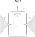
- FIG. 1 is a simplified view of a vehicle 10 that is traveling on a road.
- the vehicle 10 is traveling in the direction of the arrow D.
- At least a first imaging apparatus 1, a second imaging apparatus 2, a detection apparatus 4, and a display apparatus 7 are installed in the vehicle 10.
- vehicle in the present embodiment encompasses automobiles, industrial vehicles, and vehicles for daily life.
- Automobiles include, but are not limited to, passenger vehicles, trucks, buses, motorcycles, and trolley buses, and may include other vehicles that travel on the road.
- Industrial vehicles include industrial vehicles for agriculture and for construction.
- Industrial vehicles include, but are not limited to, forklifts and golf carts.
- Industrial vehicles for agriculture include, but are not limited to, tractors, cultivators, transplanters, binders, combines, and lawnmowers.
- Industrial vehicles for construction include, but are not limited to, bulldozers, scrapers, backhoes, cranes, dump cars, and road rollers.
- Vehicles for daily life include, but are not limited to, bicycles, wheelchairs, baby carriages, wheelbarrows, and motorized, two-wheeled standing vehicles.
- Power engines for the vehicle include, but are not limited to, internal-combustion engines including diesel engines, gasoline engines, and hydrogen engines, and electrical engines including motors.
- vehicle includes man-powered vehicles. The vehicle is not limited to the above-listed types. For example, automobiles may include industrial vehicles that can travel on the road, and the same vehicle may be included in multiple categories.
- the first imaging apparatus 1 and the second imaging apparatus 2 are side cameras with an image sensing function.
- CMOS complementary metal oxide semiconductor
- the first imaging apparatus 1 and the second imaging apparatus 2 are each fixed at the same height position, with the optical axis oriented towards or slightly downward from the horizontal direction, and can capture various subjects, such as the road edges, obstacles, and the like.
- the first imaging apparatus 1 in the present embodiment is installed on the left side of the vehicle 10 when viewing the vehicle 10 in the direction of travel thereof and captures subjects in an area R1 to the left of the vehicle 10.
- the second imaging apparatus 2 is installed on the right side of the vehicle 10 when viewing the vehicle 10 in the direction of travel thereof and captures subjects in an area R2 to the right of the vehicle 10.
- the first imaging apparatus 1 and the second imaging apparatus 2 are, for example, installed on the side mirrors.
- the first imaging apparatus 1 and the second imaging apparatus 2 respectively capture subjects to the left and right of the vehicle 10.
- the first imaging apparatus 1 may be a rear camera provided at the back of the vehicle 10 and may capture subjects on both the left and right of the vehicle 10.
- Such a rear camera includes a fisheye lens, for example.
- a controller 42 can execute the below-described processing of the present embodiment on the basis of captured images acquired from the first imaging apparatus 1 without acquiring captured images from the second imaging apparatus 2.
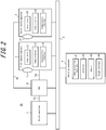
- the detection system 90 includes the first imaging apparatus 1, the second imaging apparatus 2, a network bus 3, a detection apparatus 4, dedicated wires 5a to 5c, an electronic control unit (ECU) 6, and the display apparatus 7.
- ECU electronice control unit
- the first imaging apparatus 1 includes an optical system 11, an image sensor 12, an image processor 13, and a communication interface 14.
- the optical system 11 is configured to include an aperture and a plurality of lenses and forms an image of a subject.
- the optical system 11 has a wide field of view and can image a subject (road edge, obstacle, or the like) in the area surrounding the vehicle 10.
- the image sensor 12 is, for example, a CMOS image sensor installed in the vehicle 10 and generates captured images of the area surrounding the vehicle 10 by capturing subjects imaged by the optical system 11.
- the image sensor 12 can generate images captured at a wide angle, since the optical system 11 has a wide field of view, as described above.
- the image processor 13 performs any appropriate image processing on the analog captured image generated by the image sensor 12, such as correlated double sampling (CDS), automatic gain control (AGC), and/or analog-to-digital conversion (ADC).
- CDS correlated double sampling
- ADC automatic gain control
- ADC analog-to-digital conversion
- the image processor 13 may also use a dedicated processor for image processing, for example a digital signal processor (DSP), to perform typical image processing, such as exposure adjustment, and/or image processing corresponding to activated functions and the like.
- DSP digital signal processor
- the communication interface 14 is an interface for outputting images processed by the image processor 13 to the detection apparatus 4 or the like over the network bus 3.
- the second imaging apparatus 2 includes an optical system 21, an image sensor 22, an image processor 23, and a communication interface 24. Since the functional block diagram of the second imaging apparatus 2 is similar to the functional block diagram of the first imaging apparatus 1, a description thereof is omitted.
- the network bus 3 is a physical signal line conforming to a communication standard such as controller area network (CAN), Ethernet, or the like.
- the detection apparatus 4 includes an image acquisition interface 41, the controller 42, a memory 43, and an output interface 44.
- the image acquisition interface 41 is an interface for acquiring captured images from an imaging apparatus (at least one of the first imaging apparatus 1 and the second imaging apparatus 2) that is installed in the vehicle 10 and captures images of the area surrounding the vehicle 10.
- the image acquisition interface 41 also acquires control information of the vehicle 10 from the network bus 3.
- Information indicating the travel direction (forward or backward), speed, steering angle of the steering wheel, open or closed state of the doors, presence or absence of an instruction to open or close the doors, and the like of the vehicle 10 is included in the control information of the vehicle 10.
- the control information is not limited to these examples and may include various information related to the vehicle 10.
- the control information of the vehicle 10 is used by the controller 42 to detect various states of the vehicle 10.
- the controller 42 is, for example, a dedicated microprocessor or a general-purpose central processing unit (CPU) that executes specific processing by reading specific programs.
- the controller 42 controls overall operation of the detection apparatus 4.
- the controller 42 can recognize vehicles, pedestrians, white lines, road edges, obstacles, and the like from the captured images acquired from the first imaging apparatus 1 and the second imaging apparatus 2.
- the controller 42 can measure the distance to the recognized subject by a motion stereo method or the like.
- the controller 42 can determine a parking space on the basis of information on distance measurement and on the recognition result. Details are provided below.
- the controller 42 is provided in the detection apparatus 4, which is external to the first imaging apparatus 1.
- one of the first imaging apparatus 1 and the second imaging apparatus 2 may be a master and the other may be a slave, and the controller 42 may be provided inside the master.
- the below-described parking space search process can be performed and a parking area detected by communication between the master and slave, without transmission and reception of captured images between the master and the detection apparatus 4.
- the memory 43 is, for example, a memory storing a variety of information and programs necessary for the detection apparatus 4 to operate.
- the output interface 44 outputs the result of the determination by the controller 42 and the like to the network bus 3.
- the dedicated line 5a is a physical video signal line between the first imaging apparatus 1 and the below-described ECU 6.
- Video signals that conform to the national television system committee (NTSC) system, for example, are transmitted and received over the dedicated line 5a.
- Video signals conforming to the NTSC system, for example, are similarly transmitted and received over the below-described dedicated line 5b and dedicated line 5c.
- NTSC national television system committee
- the dedicated line 5b is a video signal line between the second imaging apparatus 2 and the below-described ECU 6.
- the dedicated line 5c is a video signal line between the ECU 6 and the display apparatus 7.
- the ECU 6 performs any video synthesis process, such as switching (SW) and/or image clipping, on the images or video from the first imaging apparatus 1 and the second imaging apparatus 2.
- SW switching
- image clipping image clipping
- the display apparatus 7 displays images acquired from the detection apparatus 4 or the ECU 6. Therefore, the driver of the vehicle 10 can visually confirm the images.
- the display apparatus 7 can also receive a switching (SW) operation by the user via a button, a touch panel, or the like.
- SW switching
- parking refers to parking in a first parking mode.
- Parking in the first parking mode refers to parking in front of or behind an obstacle (another stopped or parked vehicle) on the road.
- the controller 42 starts the parking space search process upon determining that an automatic parking function has been activated by the driver of the vehicle 10 or the like and that the first imaging apparatus 1 and the second imaging apparatus 2 have been activated.
- the parking space search process includes a parking space candidate recognition process, a passing space recognition process, and a road marking recognition process.
- the parking space candidate recognition process is for determining whether a space larger than the vehicle width, i.e. the outer dimension of the vehicle 10, exists.
- TL and Sh respectively represent the total length of the vehicle 10 in the travel direction and the width of the vehicle 10.
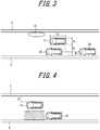
- FIG. 3 illustrates a vehicle on the road and the surrounding environment at the start of the parking space search process.
- the controller 42 Upon acquiring the captured images of the left side of the vehicle 10 from the first imaging apparatus 1 through the image acquisition interface 41, the controller 42 performs a road edge recognition process and an obstacle recognition process. On the basis of the captured images, the controller 42 detects a road edge, E, in the width direction on the left side of the road on which the vehicle 10 is traveling or an obstacle O2 on the road (another stopped or parked vehicle). For example, the controller 42 recognizes a subject that is 15 cm or taller as an obstacle and recognizes a subject under 15 cm tall as the road edge.
- the controller 42 Upon determining the presence of a road edge during the road edge recognition process, the controller 42 calculates the left-side distance, XL (m), from the first imaging apparatus 1 to the road edge, E. Upon determining the presence of an obstacle during the obstacle recognition process, the controller 42 calculates the front-rear distance, YL (m), of the obstacle O2 on the basis of the speed of the vehicle 10 and changes in images, for example.
- the front-rear distance, YL is the distance from the obstacle O2 to another obstacle O3 (another stopped or parked vehicle) in front of or behind the obstacle O2.
- the controller 42 repeats the parking space candidate recognition process until determining that a parking space exists. At this time, the vehicle 10 is preferably traveling at low speed.
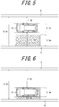
- FIG. 4 illustrates the state when the controller 42 determines that a parking space exists. Upon determining that the parking space indicated by hatching exists, the controller 42 performs the following passing space recognition process. The passing space recognition process is for determining whether there is sufficient depth for another vehicle to pass on the opposite side of the parking space candidate.
- the controller 42 Upon acquiring the captured images of the right side of the vehicle 10 from the second imaging apparatus 2, the controller 42 performs the road edge recognition process and the obstacle recognition process using the captured images. Upon determining that no obstacle exists in the width direction, the controller 42 determines whether a road edge exists in the width direction, and if so, calculates the distance from the second imaging apparatus 2 to the road edge, E, as the right-side distance, ZR (m). Conversely, upon determining that an obstacle is present, the controller 42 calculates the distance from the second imaging apparatus 2 to the obstacle as the right-side distance, ZR. When no road edge exists, the controller 42 sets the right-side distance, ZR, to a predetermined value that is sufficiently larger than the below-described necessary road width.
- the controller 42 determines whether the sum of the left-side distance, XL, calculated in the parking space candidate recognition process, the right-side distance, ZR, calculated in the passing space recognition process, and the vehicle width, Sh, is equal to or greater than a predetermined necessary road width.
- the necessary road width is the road width that needs to be set aside for other vehicles to pass by when the vehicle is parked.
- the necessary road width is 8.2 m in the present embodiment.
- the necessary road width of 8.2 m is the sum of the 0.8 m space from the road edge, E, to the vehicle 10, the 2.7 m width of the vehicle 10 (in the case of a private automobile), the 2.7 m width of another vehicle, and an extra 2 m in the left-right direction of the other vehicle.
- the setting of these values (such as the vehicle width) can be changed as necessary.
- the controller 42 determines whether the following inequality (1) holds (for parking in the first parking mode). XL + ZR + Sh ⁇ 8.2
- the hatched portion is a parking space candidate.
- no obstacle is illustrated in FIG. 5 .
- XL + ZR + Sh 8.2. Since the aforementioned inequality (1) holds, the controller 42 determines that parking is possible.
- XL + ZR + Sh 8.2. Since the aforementioned inequality (for parking in the first parking mode) holds, the controller 42 determines that parking is possible.
- parking refers to parking in the first parking mode.
- parking in the first parking mode may refer to parallel parking, i.e. parking between a plurality of other vehicles that are parked in a line.
- parking may refer to parking in a second parking mode.
- Parking in the second parking mode refers to parking alongside, i.e. to the left or right of an obstacle (another stopped or parked vehicle) on the road.
- the controller 42 may determine whether to park in the first parking mode or the second parking mode in accordance with input from the user, or the controller 42 may determine whether parking is possible in each of the first parking mode and the second parking.
- the controller 42 may determine the parking mode (parking in the first parking mode or parking in the second parking mode) of another vehicle that is already parked nearby and may determine whether the vehicle 10 can be parked in the same mode.
- the controller 42 may also determine on a priority basis whether parking in the first parking mode is possible or may determine whether to park in the first parking mode or the second parking mode in accordance with the value of XL + ZR + Sh.
- an example of the necessary road width for parking is 10.2 m.
- the necessary road width of 10.2 m is the sum of the total length 5.5 m of the vehicle 10 in the travel direction, the 2.7 m width of another vehicle 10, and an extra 2 m in the left-right direction of the other vehicle.
- the controller 42 determines whether the following inequality (2) holds (for parking in the second parking mode). XL + ZR + Sh ⁇ 10.2
- FIG. 8 illustrates the state when the vehicle 10 is searching for a parking area while traveling, the vehicle 10 is facing the travel direction (the left-right direction in the figure). Once the vehicle 10 has parked in the second parking mode, the vehicle 10 will face a direction that crosses the road (the up-down direction in the figure).
- the controller 42 can perform the parking space candidate recognition process and the passing space recognition process even when the vehicle 10 is traveling diagonally (in a non-parallel state) relative to the road edge, E.
- FIG. 9 illustrates an example of the positional relationship between a parking space on the road and the vehicle 10 during a parking space search in this case.
- the controller 42 calculates the distance to the road edge or an obstacle as a direction component that is perpendicular to the road edge of the distance from the first imaging apparatus 1 or the second imaging apparatus 2, which are the reference points of the vehicle 10 from which distances to the road edge or to the obstacle are measured.
- ⁇ cos ⁇ + ⁇ cos ⁇ +Shcos ⁇ ⁇ 8.2 In the case of parking in the second mode, it suffices for the right side of the aforementioned inequality (3) to be 10.2.
- ⁇ is the distance from the reference point for measurement by the first imaging apparatus 1 of the vehicle 10 to the intersection of the optical axis of the first imaging apparatus 1 with the road edge or an obstacle on the left side of the vehicle 10, when looking in the perpendicular direction.
- ⁇ is the distance from the reference point for measurement by the second imaging apparatus 2 of the vehicle 10 to the intersection of the optical axis of the second imaging apparatus 2 with the road edge or an obstacle on the right side of the vehicle 10, when looking in the perpendicular direction.
- FIG. 10 illustrates an example of the vehicle 10 on the road and the surrounding environment during the passing space recognition process at this time.
- the right-side distance, ZR necessary to satisfy inequality (1) is unattainable, since an obstacle O1 is present on the right side of the vehicle 10. Therefore, the controller 42 continues the passing space recognition process while the vehicle 10 is traveling.
- FIG. 11 illustrates the vehicle and the surrounding environment after completion of the passing space recognition process.
- the road marking recognition process is for recognizing road markings drawn on the road, road signs installed on the road, and the like and to determine whether a parking space can be definitively selected.
- the controller 42 determines that parking is not possible when recognizing a no-parking marking or a disabled marking in the image captured by the first imaging apparatus 1.
- the controller 42 also determines that parking is not possible when determining, from the images captured by the first imaging apparatus 1 and the second imaging apparatus 2, that the vehicle 10 is within 5 m of an intersection.
- FIG. 12 illustrates an example of the vehicle 10 and the surrounding environment upon completion of the automatic parking control. Since a variety of techniques have been proposed as methods of automatic parking control, further description is omitted.
- the vehicle 10 is parked on the left side in the travel direction.
- the controller 42 may instead determine whether parking is possible on the right side in the travel direction by performing the passing space recognition process on the basis of captured images from the first imaging apparatus 1 and performing the parking space candidate recognition process on the basis of captured images from the second imaging apparatus 2.
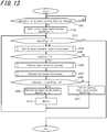
- FIG. 13 is a flowchart illustrating operations by the controller 42 of the detection apparatus 4. The operations by the controller 42 are described below in accordance with FIG. 13 .
- step S101 the controller 42 determines whether the automatic parking function is activated.
- the Searchflag is a flag indicating the state of the parking space candidate recognition process.
- step S101 is No, the controller 42 repeats step S101.
- step S104 the controller 42 performs the parking space candidate recognition process in step S104. Details on step S104 are provided in FIG. 14 .
- Pflag is a flag indicating whether a parking space candidate exists.
- step S105 determines whether the result of step S105 is Yes.
- the controller 42 performs the passing space recognition process in step S106. Details on step S106 are provided in FIG. 15 .
- step S107 the controller 42 performs the road marking recognition process in step S107. Details on step S107 are provided in FIG. 16 .
- step S110 after step S109, the controller 42 notifies other control apparatuses of the vehicle 10 over the network bus 3 that automatic parking is possible. After step S110 or step Sill, the controller 42 executes step S103.
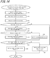
- FIG. 14 illustrates a subroutine of step S104 (the parking space candidate recognition process).
- the parking space candidate recognition process of FIG. 14 is described below.
- step S11 the controller 42 acquires captured images from the first imaging apparatus 1.
- step S12 and step S13 the controller 42 uses the captured images to perform the road edge recognition process and the obstacle recognition process.
- step S14 the controller 42 determines whether a road edge has been recognized.
- the controller 42 calculates the left-side distance to the road edge and sets XL to the result in step S15.
- step S16 the controller 42 determines whether an obstacle has been recognized during the obstacle recognition process.
- step S16 When the result of step S16 is Yes, the controller 42 calculates the front-rear distance, YL, of the obstacle in step S17. When the result of step S16 is No, the controller 42 sets the front-rear distance, YL, in step S18 to a predetermined value that is sufficiently larger than the total length, TL, of the vehicle 10 in the travel direction.
- step S19 the controller 42 determines in step S19 whether the front-rear distance, YL, is equal to or greater than the total length, TL, of the vehicle 10 in the travel direction.
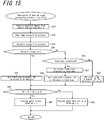
- FIG. 15 illustrates a subroutine of step S106 (the passing space recognition process).
- step S31 the controller 42 acquires captured images from the second imaging apparatus 2.
- step S32 and step S33 the controller 42 uses the captured images to perform the road edge recognition process and the obstacle recognition process.
- step S34 the controller 42 determines whether an obstacle has been recognized during the obstacle recognition process.
- the controller 42 calculates the right-side distance, ZR, to the obstacle in step S35.
- the controller 42 determines in step S36 whether a road edge has been recognized in the road edge recognition process.
- the controller 42 calculates the distance to the road edge in step S37.
- step S38 the controller 42 sets the right-side distance, ZR, to this distance.
- the controller 42 in step S39 sets the right-side distance, ZR, to a sufficiently larger value than the necessary road width (for example, the maximum imageable distance).
- step S40 after step S35, step S38, or step S39, the controller 42 determines whether expression (1), i.e. the inequality ZR + XL + Sh (vehicle width) ⁇ 8.2, holds.
- Expression (1) indicates a condition for parking in the first parking mode.
- the controller 42 determines whether the inequality in expression (2) holds, in which the right side of expression (1) is set to 10.2.
- the controller 42 may determine whether parking is possible in both of the first parking mode and the second parking mode or may make the determination for only one of the modes.
- FIG. 16 illustrates a subroutine of step S107 (the road marking recognition process).
- the controller 42 calculates, on the basis of captured images acquired from the first imaging apparatus 1 and the second imaging apparatus 2, the distance from the first imaging apparatus 1 or the second imaging apparatus 2 to the road edge of the road on which the vehicle 10 is traveling or to an obstacle on the road. Furthermore, on the basis of the calculated distance and information on the outer dimension of the vehicle 10, the controller 42 determines whether travel on the road by other vehicles will be possible after the vehicle 10 has parked on the road. Therefore, the controller 42 determines whether the vehicle can park in a parking space without parking lines, for example, after taking into consideration the size of the vehicle to determine whether there is room for other vehicles to travel on the road. Accordingly, the controller 42 can detect an appropriate parking position that does not obstruct other vehicles. Furthermore, automatic parking can be implemented at low cost without necessarily increasing the number of on-vehicle devices.
- the controller 42 in the present embodiment can use the vehicle width, Sh, or the total length, TL, in the travel direction as information on the outer dimension of the vehicle 10 to determine whether other vehicles can travel on the road when the vehicle 10 parks in the first parking mode or the second parking mode. Therefore, the controller 42 can accurately determine whether other vehicles can travel on the road in accordance with whether the vehicle 10 parks in the first parking mode or the second parking mode.
- the controller 42 of the present embodiment determines whether travel on the road by other vehicles will be possible after the vehicle 10 has parked on the road on the basis of a direction component, perpendicular to the road edge, of the distance from the first imaging apparatus 1 or the second imaging apparatus 2 to the road edge or to an obstacle. Therefore, the controller 42 can accurately calculate the width of the road even when the vehicle 10 is traveling at an angle (in a non-parallel state) relative to the road edge.
- the controller 42 of the detection apparatus 4 may be configured by a computer.
- a program containing a description of the processing for achieving the functions is stored within the computer or in an external memory, and the controller 42 is implemented by the CPU of the computer reading and executing the program.
- a program can, for example, be distributed by the sale, transfer, lending, or the like of a portable recording medium such as a digital versatile disk (DVD) or a compact disk-read only memory (CD-ROM).
- DVD digital versatile disk
- CD-ROM compact disk-read only memory
- Such a program can also, for example, be distributed by being stored in the memory of a server on a network and then transferred from the server to another computer over the network.
- the computer that executes such a program can temporarily store, in its own memory, the program recorded on the portable recording medium or transferred from the server.
- a computer may read the program directly from the portable recording medium and execute processing in accordance with the program. Furthermore, each time the program is transferred from the server to the computer, the computer may execute processing in accordance with the received program.
Landscapes
- Engineering & Computer Science (AREA)
- Physics & Mathematics (AREA)
- General Physics & Mathematics (AREA)
- Mechanical Engineering (AREA)
- Multimedia (AREA)
- Theoretical Computer Science (AREA)
- Automation & Control Theory (AREA)
- Transportation (AREA)
- Traffic Control Systems (AREA)
- Image Analysis (AREA)
Abstract
Description
- The present application claims priority to and the benefit of Japanese Patent Application No.
2015-149857 filed July 29, 2015 - The present disclosure relates to a detection apparatus, an imaging apparatus, a vehicle, and a detection method.
- A technique is known for detecting a parking space using distance data obtained by calculation on the basis of an image captured by an on-vehicle camera (for example, patent literature (PTL) 1). However, on a road which does not have parking lines, simply detecting a parking space allows a vehicle to park but the vehicle may block the movement of other vehicles or become an obstacle for other vehicles depending on the surrounding conditions, such as the road width.
- PTL 1:
JP H6-111198 A - A detection apparatus according to an embodiment of the present disclosure includes an image acquisition interface and a controller. The image acquisition interface is configured to acquire captured images from an imaging apparatus that is installed in a vehicle and captures images of an area surrounding the vehicle. The controller is configured to calculate, on the basis of the captured images, a distance from the imaging apparatus to a road edge in a width direction of a road on which the vehicle is traveling or to an obstacle on the road. The controller is configured to determine, on the basis of the calculated distance and information on an outer dimension of the vehicle, whether travel on the road by other vehicles will be possible after the vehicle has parked on the road.
- An imaging apparatus according to an embodiment of the present disclosure includes an image sensor and a controller. The image sensor is installed in a vehicle and generates captured images of an area surrounding the vehicle. The controller is configured to calculate, on the basis of the captured images, a distance from the image sensor to a road edge in a width direction of a road on which the vehicle is traveling or to an obstacle on the road. The controller is configured to determine, on the basis of the calculated distance and information on an outer dimension of the vehicle, whether travel on the road by other vehicles will be possible after the vehicle has parked on the road.
- A vehicle according to an embodiment of the present disclosure is a vehicle with an imaging apparatus installed therein, the imaging apparatus comprising an image acquisition interface and a controller. The image acquisition interface is configured to acquire captured images from the imaging apparatus that is installed in the vehicle and captures images of an area surrounding the vehicle. The controller is configured to calculate, on the basis of the captured images, a distance from the imaging apparatus to a road edge in a width direction of a road on which the vehicle is traveling or to an obstacle on the road. The controller is configured to determine, on the basis of the calculated distance and information on an outer dimension of the vehicle, whether travel on the road by other vehicles will be possible after the vehicle has parked on the road.
- A detection method according to an embodiment of the present disclosure is used in a detection apparatus and comprises acquiring captured images from an imaging apparatus that is installed in a vehicle and captures images of an area surrounding the vehicle. The detection method, according to an embodiment of the present disclosure, that is used in a detection apparatus further comprises calculating, on the basis of the captured images, a distance from the imaging apparatus to a road edge in a width direction of a road on which the vehicle is traveling or to an obstacle on the road. The detection method, according to an embodiment of the present disclosure, that is used in a detection apparatus further comprises determining, on the basis of the calculated distance and information on an outer dimension of the vehicle, whether travel on the road by other vehicles will be possible after the vehicle has parked on the road.
- In the accompanying drawings:
-
FIG. 1 illustrates a vehicle according to an embodiment of the present disclosure; -
FIG. 2 is a functional block diagram of a detection system including a detection apparatus according to an embodiment of the present disclosure; -
FIG. 3 illustrates an example of a vehicle on the road and the surrounding environment at the start of a parking space search process; -
FIG. 4 illustrates an example of a vehicle on the road and the surrounding environment during a parking space candidate recognition process; -
FIG. 5 illustrates a first example of the positional relationship between a parking space on the road and a vehicle during a parking space search; -
FIG. 6 illustrates a second example of the positional relationship between a parking space on the road and a vehicle during a parking space search; -
FIG. 7 illustrates a third example of the positional relationship between a parking space on the road and a vehicle during a parking space search; -
FIG. "8 illustrates a fourth example of the positional relationship between a parking space on the road and a vehicle during a parking space search; -
FIG. 9 illustrates a fifth example of the positional relationship between a parking space on the road and a vehicle during a parking space search; -
FIG. 10 illustrates an example of a vehicle on the road and the surrounding environment during a passing space recognition process; -
FIG. 11 illustrates an example of a vehicle and the surrounding environment after completion of the passing space recognition process; -
FIG. 12 illustrates an example of a vehicle on the road and the surrounding environment upon completion of a road marking recognition process and automatic parking control; -
FIG. 13 is a flowchart illustrating operations by a controller in the detection apparatus ofFIG. 2 ; -
FIG. 14 illustrates a subroutine of a parking space candidate recognition process inFIG. 13 ; -
FIG. 15 illustrates a subroutine of a passing space recognition process inFIG. 13 ; and -
FIG. 16 illustrates a subroutine of a road marking recognition process inFIG. 13 . - A detection apparatus according to an embodiment of the present disclosure includes an image acquisition interface and a controller. On the basis of captured images acquired by the image acquisition interface, the controller detects the edge of the road on which the vehicle is traveling or an obstacle on the road and calculates the distance to the detected road edge or obstacle. On the basis of the calculated distance and information on the outer dimension of the vehicle, the controller determines whether travel on the road by other vehicles will be possible after the vehicle has parked on the road. Therefore, the detection apparatus can determine whether the vehicle can park in a parking space without parking lines, for example, after taking into consideration the size of the vehicle to determine whether there is room for other vehicles to travel on the road. Accordingly, the detection apparatus can detect an appropriate parking position that does not obstruct other vehicles. Furthermore, the detection apparatus can implement automatic parking at low cost without necessarily increasing the number of on-vehicle devices. An embodiment of the present disclosure is described below with reference to the drawings.
-
FIG. 1 is a simplified view of avehicle 10 that is traveling on a road. Thevehicle 10 is traveling in the direction of the arrow D. At least afirst imaging apparatus 1, asecond imaging apparatus 2, adetection apparatus 4, and adisplay apparatus 7 are installed in thevehicle 10. The term "vehicle" in the present embodiment encompasses automobiles, industrial vehicles, and vehicles for daily life. Automobiles include, but are not limited to, passenger vehicles, trucks, buses, motorcycles, and trolley buses, and may include other vehicles that travel on the road. Industrial vehicles include industrial vehicles for agriculture and for construction. Industrial vehicles include, but are not limited to, forklifts and golf carts. Industrial vehicles for agriculture include, but are not limited to, tractors, cultivators, transplanters, binders, combines, and lawnmowers. Industrial vehicles for construction include, but are not limited to, bulldozers, scrapers, backhoes, cranes, dump cars, and road rollers. Vehicles for daily life include, but are not limited to, bicycles, wheelchairs, baby carriages, wheelbarrows, and motorized, two-wheeled standing vehicles. Power engines for the vehicle include, but are not limited to, internal-combustion engines including diesel engines, gasoline engines, and hydrogen engines, and electrical engines including motors. The term "vehicle" includes man-powered vehicles. The vehicle is not limited to the above-listed types. For example, automobiles may include industrial vehicles that can travel on the road, and the same vehicle may be included in multiple categories. - The
first imaging apparatus 1 and thesecond imaging apparatus 2 are side cameras with an image sensing function. A charge coupled device (CCD) or a complementary metal oxide semiconductor (CMOS), for example, is suitably used as such a side camera. Thefirst imaging apparatus 1 and thesecond imaging apparatus 2 are each fixed at the same height position, with the optical axis oriented towards or slightly downward from the horizontal direction, and can capture various subjects, such as the road edges, obstacles, and the like. Thefirst imaging apparatus 1 in the present embodiment is installed on the left side of thevehicle 10 when viewing thevehicle 10 in the direction of travel thereof and captures subjects in an area R1 to the left of thevehicle 10. Thesecond imaging apparatus 2 is installed on the right side of thevehicle 10 when viewing thevehicle 10 in the direction of travel thereof and captures subjects in an area R2 to the right of thevehicle 10. Thefirst imaging apparatus 1 and thesecond imaging apparatus 2 are, for example, installed on the side mirrors. - In the present embodiment, the
first imaging apparatus 1 and thesecond imaging apparatus 2 respectively capture subjects to the left and right of thevehicle 10. As an alternative example, thefirst imaging apparatus 1 may be a rear camera provided at the back of thevehicle 10 and may capture subjects on both the left and right of thevehicle 10. Such a rear camera includes a fisheye lens, for example. Acontroller 42 can execute the below-described processing of the present embodiment on the basis of captured images acquired from thefirst imaging apparatus 1 without acquiring captured images from thesecond imaging apparatus 2. - Next, the configuration of a
detection system 90 installed in thevehicle 10 is described in detail with reference toFIG. 2 . Thedetection system 90 includes thefirst imaging apparatus 1, thesecond imaging apparatus 2, anetwork bus 3, adetection apparatus 4,dedicated wires 5a to 5c, an electronic control unit (ECU) 6, and thedisplay apparatus 7. - The
first imaging apparatus 1 includes anoptical system 11, animage sensor 12, an image processor 13, and acommunication interface 14. - The
optical system 11 is configured to include an aperture and a plurality of lenses and forms an image of a subject. In the present embodiment, theoptical system 11 has a wide field of view and can image a subject (road edge, obstacle, or the like) in the area surrounding thevehicle 10. - The
image sensor 12 is, for example, a CMOS image sensor installed in thevehicle 10 and generates captured images of the area surrounding thevehicle 10 by capturing subjects imaged by theoptical system 11. Here, theimage sensor 12 can generate images captured at a wide angle, since theoptical system 11 has a wide field of view, as described above. - The image processor 13 performs any appropriate image processing on the analog captured image generated by the
image sensor 12, such as correlated double sampling (CDS), automatic gain control (AGC), and/or analog-to-digital conversion (ADC). The image processor 13 may also use a dedicated processor for image processing, for example a digital signal processor (DSP), to perform typical image processing, such as exposure adjustment, and/or image processing corresponding to activated functions and the like. - The
communication interface 14 is an interface for outputting images processed by the image processor 13 to thedetection apparatus 4 or the like over thenetwork bus 3. - The
second imaging apparatus 2 includes anoptical system 21, animage sensor 22, animage processor 23, and acommunication interface 24. Since the functional block diagram of thesecond imaging apparatus 2 is similar to the functional block diagram of thefirst imaging apparatus 1, a description thereof is omitted. - The
network bus 3 is a physical signal line conforming to a communication standard such as controller area network (CAN), Ethernet, or the like. - The
detection apparatus 4 includes animage acquisition interface 41, thecontroller 42, amemory 43, and anoutput interface 44. - The
image acquisition interface 41 is an interface for acquiring captured images from an imaging apparatus (at least one of thefirst imaging apparatus 1 and the second imaging apparatus 2) that is installed in thevehicle 10 and captures images of the area surrounding thevehicle 10. Theimage acquisition interface 41 also acquires control information of thevehicle 10 from thenetwork bus 3. Information indicating the travel direction (forward or backward), speed, steering angle of the steering wheel, open or closed state of the doors, presence or absence of an instruction to open or close the doors, and the like of thevehicle 10 is included in the control information of thevehicle 10. However, the control information is not limited to these examples and may include various information related to thevehicle 10. The control information of thevehicle 10 is used by thecontroller 42 to detect various states of thevehicle 10. - The
controller 42 is, for example, a dedicated microprocessor or a general-purpose central processing unit (CPU) that executes specific processing by reading specific programs. Thecontroller 42 controls overall operation of thedetection apparatus 4. Thecontroller 42 can recognize vehicles, pedestrians, white lines, road edges, obstacles, and the like from the captured images acquired from thefirst imaging apparatus 1 and thesecond imaging apparatus 2. Thecontroller 42 can measure the distance to the recognized subject by a motion stereo method or the like. Thecontroller 42 can determine a parking space on the basis of information on distance measurement and on the recognition result. Details are provided below. - In the present embodiment, the
controller 42 is provided in thedetection apparatus 4, which is external to thefirst imaging apparatus 1. As an alternative example, one of thefirst imaging apparatus 1 and thesecond imaging apparatus 2 may be a master and the other may be a slave, and thecontroller 42 may be provided inside the master. In this case, the below-described parking space search process can be performed and a parking area detected by communication between the master and slave, without transmission and reception of captured images between the master and thedetection apparatus 4. - The
memory 43 is, for example, a memory storing a variety of information and programs necessary for thedetection apparatus 4 to operate. - The
output interface 44 outputs the result of the determination by thecontroller 42 and the like to thenetwork bus 3. - The
dedicated line 5a is a physical video signal line between thefirst imaging apparatus 1 and the below-describedECU 6. Video signals that conform to the national television system committee (NTSC) system, for example, are transmitted and received over thededicated line 5a. Video signals conforming to the NTSC system, for example, are similarly transmitted and received over the below-describeddedicated line 5b and dedicated line 5c. - The
dedicated line 5b is a video signal line between thesecond imaging apparatus 2 and the below-describedECU 6. - The dedicated line 5c is a video signal line between the
ECU 6 and thedisplay apparatus 7. - The
ECU 6 performs any video synthesis process, such as switching (SW) and/or image clipping, on the images or video from thefirst imaging apparatus 1 and thesecond imaging apparatus 2. - The
display apparatus 7 displays images acquired from thedetection apparatus 4 or theECU 6. Therefore, the driver of thevehicle 10 can visually confirm the images. Thedisplay apparatus 7 can also receive a switching (SW) operation by the user via a button, a touch panel, or the like. - The detection method of the present embodiment is described below in detail. In the present embodiment, parking refers to parking in a first parking mode. Parking in the first parking mode refers to parking in front of or behind an obstacle (another stopped or parked vehicle) on the road.
- The
controller 42 starts the parking space search process upon determining that an automatic parking function has been activated by the driver of thevehicle 10 or the like and that thefirst imaging apparatus 1 and thesecond imaging apparatus 2 have been activated. The parking space search process includes a parking space candidate recognition process, a passing space recognition process, and a road marking recognition process. The parking space candidate recognition process is for determining whether a space larger than the vehicle width, i.e. the outer dimension of thevehicle 10, exists. In the following explanation, TL and Sh respectively represent the total length of thevehicle 10 in the travel direction and the width of thevehicle 10.FIG. 3 illustrates a vehicle on the road and the surrounding environment at the start of the parking space search process. - Upon acquiring the captured images of the left side of the
vehicle 10 from thefirst imaging apparatus 1 through theimage acquisition interface 41, thecontroller 42 performs a road edge recognition process and an obstacle recognition process. On the basis of the captured images, thecontroller 42 detects a road edge, E, in the width direction on the left side of the road on which thevehicle 10 is traveling or an obstacle O2 on the road (another stopped or parked vehicle). For example, thecontroller 42 recognizes a subject that is 15 cm or taller as an obstacle and recognizes a subject under 15 cm tall as the road edge. - Upon determining the presence of a road edge during the road edge recognition process, the
controller 42 calculates the left-side distance, XL (m), from thefirst imaging apparatus 1 to the road edge, E. Upon determining the presence of an obstacle during the obstacle recognition process, thecontroller 42 calculates the front-rear distance, YL (m), of the obstacle O2 on the basis of the speed of thevehicle 10 and changes in images, for example. The front-rear distance, YL, is the distance from the obstacle O2 to another obstacle O3 (another stopped or parked vehicle) in front of or behind the obstacle O2. Thecontroller 42 determines whether the front-rear distance, YL, is equal to or greater than the total length, TL, of thevehicle 10 in the travel direction (information on the outer dimension of the vehicle 10). When no obstacle exists, the front-rear distance, YL, is set to a predetermined distance that is sufficiently larger than the total length, TL, of thevehicle 10 in the travel direction. In other words, thecontroller 42 determines whether a parking space candidate for thevehicle 10 exists in front or behind the obstacle O2. Upon determining that a parking space exists, thecontroller 42 sets a flag in thememory 43 indicating the existence of a parking space candidate (Pflag = 1). InFIG. 3 , thecontroller 42 determines that no parking space candidate exists (Pflag = 0), since the obstacle O2 is present on the left side in the travel direction of thevehicle 10. - The
controller 42 repeats the parking space candidate recognition process until determining that a parking space exists. At this time, thevehicle 10 is preferably traveling at low speed.FIG. 4 illustrates the state when thecontroller 42 determines that a parking space exists. Upon determining that the parking space indicated by hatching exists, thecontroller 42 performs the following passing space recognition process. The passing space recognition process is for determining whether there is sufficient depth for another vehicle to pass on the opposite side of the parking space candidate. - Upon acquiring the captured images of the right side of the
vehicle 10 from thesecond imaging apparatus 2, thecontroller 42 performs the road edge recognition process and the obstacle recognition process using the captured images. Upon determining that no obstacle exists in the width direction, thecontroller 42 determines whether a road edge exists in the width direction, and if so, calculates the distance from thesecond imaging apparatus 2 to the road edge, E, as the right-side distance, ZR (m). Conversely, upon determining that an obstacle is present, thecontroller 42 calculates the distance from thesecond imaging apparatus 2 to the obstacle as the right-side distance, ZR. When no road edge exists, thecontroller 42 sets the right-side distance, ZR, to a predetermined value that is sufficiently larger than the below-described necessary road width. - The
controller 42 determines whether the sum of the left-side distance, XL, calculated in the parking space candidate recognition process, the right-side distance, ZR, calculated in the passing space recognition process, and the vehicle width, Sh, is equal to or greater than a predetermined necessary road width. The necessary road width is the road width that needs to be set aside for other vehicles to pass by when the vehicle is parked. As an example, the necessary road width is 8.2 m in the present embodiment. The necessary road width of 8.2 m is the sum of the 0.8 m space from the road edge, E, to thevehicle 10, the 2.7 m width of the vehicle 10 (in the case of a private automobile), the 2.7 m width of another vehicle, and an extra 2 m in the left-right direction of the other vehicle. However, the setting of these values (such as the vehicle width) can be changed as necessary. Thecontroller 42 determines whether the following inequality (1) holds (for parking in the first parking mode).
-
FIG. 5 illustrates an example of the positional relationship between a parking space on the road and thevehicle 10 during a parking space search when, for example, XL = 4.5 (m), ZR = 1.0 (m), and the vehicle width, Sh, = 2.7 (m). The hatched portion is a parking space candidate. For the sake of simplicity, no obstacle is illustrated inFIG. 5 . In this case, XL + ZR + Sh = 8.2. Since the aforementioned inequality (1) holds, thecontroller 42 determines that parking is possible. -
FIG. 6 illustrates an example of the positional relationship between a parking space on the road and thevehicle 10 during a parking space search when, for example, XL = 0.8 (m), ZR = 4.7 (m), and the vehicle width, Sh, = 2.7 (m). In this case, XL + ZR + Sh = 8.2. Since the aforementioned inequality (for parking in the first parking mode) holds, thecontroller 42 determines that parking is possible. - In the present embodiment, parking refers to parking in the first parking mode. However, in another embodiment, parking in the first parking mode may refer to parallel parking, i.e. parking between a plurality of other vehicles that are parked in a line. In an alternative example, parking may refer to parking in a second parking mode. Parking in the second parking mode refers to parking alongside, i.e. to the left or right of an obstacle (another stopped or parked vehicle) on the road. The
controller 42 may determine whether to park in the first parking mode or the second parking mode in accordance with input from the user, or thecontroller 42 may determine whether parking is possible in each of the first parking mode and the second parking. Furthermore, thecontroller 42 may determine the parking mode (parking in the first parking mode or parking in the second parking mode) of another vehicle that is already parked nearby and may determine whether thevehicle 10 can be parked in the same mode. Thecontroller 42 may also determine on a priority basis whether parking in the first parking mode is possible or may determine whether to park in the first parking mode or the second parking mode in accordance with the value of XL + ZR + Sh. - When parking in the second parking mode, an example of the necessary road width for parking is 10.2 m. The necessary road width of 10.2 m is the sum of the total length 5.5 m of the
vehicle 10 in the travel direction, the 2.7 m width of anothervehicle 10, and an extra 2 m in the left-right direction of the other vehicle. However, the setting of these values can be changed as necessary. Instead of the aforementioned inequality (1), thecontroller 42 determines whether the following inequality (2) holds (for parking in the second parking mode).
-
FIG. 7 illustrates an example of the positional relationship between a parking space on the road and thevehicle 10 during a parking space search when, for example, XL = 6.5 (m), ZR = 1.0 (m), and the vehicle width, Sh, = 2.7 (m). In this case, XL + ZR + Sh = 10.2. Since the aforementioned inequality (2) holds, thecontroller 42 determines that parking is possible. -
FIG. 8 illustrates an example of the positional relationship between a parking space on the road and thevehicle 10 during a parking space search when, for example, XL = 0.8 (m), ZR = 6.7 (m), and the vehicle width, Sh, = 2.7 (m). In this case, thecontroller 42 determines that the aforementioned inequality (2) holds, because XL + ZR + Sh = 10.2. SinceFIG. 8 illustrates the state when thevehicle 10 is searching for a parking area while traveling, thevehicle 10 is facing the travel direction (the left-right direction in the figure). Once thevehicle 10 has parked in the second parking mode, thevehicle 10 will face a direction that crosses the road (the up-down direction in the figure). - As a different function, the
controller 42 can perform the parking space candidate recognition process and the passing space recognition process even when thevehicle 10 is traveling diagonally (in a non-parallel state) relative to the road edge, E.FIG. 9 illustrates an example of the positional relationship between a parking space on the road and thevehicle 10 during a parking space search in this case. When, on the basis of information such as the steering angle of the body of thevehicle 10, thecontroller 42 determines that thevehicle 10 is traveling at an angle θ relative to the road edge, E, thecontroller 42 determines whether the following inequality (3) holds. At this time, thecontroller 42 calculates the distance to the road edge or an obstacle as a direction component that is perpendicular to the road edge of the distance from thefirst imaging apparatus 1 or thesecond imaging apparatus 2, which are the reference points of thevehicle 10 from which distances to the road edge or to the obstacle are measured.
first imaging apparatus 1 of thevehicle 10 to the intersection of the optical axis of thefirst imaging apparatus 1 with the road edge or an obstacle on the left side of thevehicle 10, when looking in the perpendicular direction. Furthermore, β is the distance from the reference point for measurement by thesecond imaging apparatus 2 of thevehicle 10 to the intersection of the optical axis of thesecond imaging apparatus 2 with the road edge or an obstacle on the right side of thevehicle 10, when looking in the perpendicular direction. - Returning now to the passing space recognition process, when the
vehicle 10 is traveling parallel to the road edge, E, thecontroller 42 determines that no passing space exists upon determining that the aforementioned expression (1) does not hold. Thecontroller 42 then clears the flag in thememory 43 indicating that a passing space exists (Pathflag = 0).FIG. 10 illustrates an example of thevehicle 10 on the road and the surrounding environment during the passing space recognition process at this time. InFIG. 10 , the right-side distance, ZR, necessary to satisfy inequality (1) is unattainable, since an obstacle O1 is present on the right side of thevehicle 10. Therefore, thecontroller 42 continues the passing space recognition process while thevehicle 10 is traveling. - Upon determining that the aforementioned inequality (1) holds, the
controller 42 determines that a passing space exists and sets the flag indicating the existence of a passing space (Pathflag = 1).FIG. 11 illustrates the vehicle and the surrounding environment after completion of the passing space recognition process. - Upon completion of the passing space recognition process, the
controller 42 performs the road marking recognition process. The road marking recognition process is for recognizing road markings drawn on the road, road signs installed on the road, and the like and to determine whether a parking space can be definitively selected. - For example, the
controller 42 determines that parking is not possible when recognizing a no-parking marking or a disabled marking in the image captured by thefirst imaging apparatus 1. Thecontroller 42 also determines that parking is not possible when determining, from the images captured by thefirst imaging apparatus 1 and thesecond imaging apparatus 2, that thevehicle 10 is within 5 m of an intersection. At this time, thecontroller 42 sets a flag indicating that parking is prohibited in the memory 43 (Wflag = 1). Conversely, thecontroller 42 clears this flag in thememory 43 when determining that parking is possible (Wflag = 0). - The
controller 42 refers to thememory 43 and determines whether the condition "Pathflag = 1 and Wflag = 0" is satisfied. When the condition is satisfied, thevehicle 10 performs automatic parking control and parks itself in the parking space that was found in the parking space candidate recognition process.FIG. 12 illustrates an example of thevehicle 10 and the surrounding environment upon completion of the automatic parking control. Since a variety of techniques have been proposed as methods of automatic parking control, further description is omitted. - In the present embodiment, the
vehicle 10 is parked on the left side in the travel direction. However, thecontroller 42 may instead determine whether parking is possible on the right side in the travel direction by performing the passing space recognition process on the basis of captured images from thefirst imaging apparatus 1 and performing the parking space candidate recognition process on the basis of captured images from thesecond imaging apparatus 2. -
FIG. 13 is a flowchart illustrating operations by thecontroller 42 of thedetection apparatus 4. The operations by thecontroller 42 are described below in accordance withFIG. 13 . - In step S101, the
controller 42 determines whether the automatic parking function is activated. When the result of step S101 is Yes, thecontroller 42 sets the Searchflag in thememory 43, i.e. Searchflag = 1, in step S102. The Searchflag is a flag indicating the state of the parking space candidate recognition process. When step S101 is No, thecontroller 42 repeats step S101. - In step S103, the
controller 42 determines whether Searchflag = 0 and terminates the processing flow when the result of step S103 is Yes. - Conversely, when the result of step S103 is No, the
controller 42 performs the parking space candidate recognition process in step S104. Details on step S104 are provided inFIG. 14 . - Next, in step S105, the
controller 42 determines whether Pflag = 1 in thememory 43. As described above, Pflag is a flag indicating whether a parking space candidate exists. When the result of step S105 is No, thecontroller 42 continues the parking space candidate recognition process in step S111 and therefore leaves the Searchflag set, i.e. Searchflag = 1. - Conversely, when the result of step S105 is Yes, the
controller 42 performs the passing space recognition process in step S106. Details on step S106 are provided inFIG. 15 . After step S106, thecontroller 42 performs the road marking recognition process in step S107. Details on step S107 are provided inFIG. 16 . - In step S108, the
controller 42 next determines whether "Pathflag = 1 and Wflag = 0" is satisfied. As described above, Pathflag and Wflag are flags respectively indicating that a parking space exists and that parking is prohibited. When the result of step S108 is Yes, thecontroller 42 completes the parking space search process in step S109 and clears the Searchflag, i.e. Searchflag = 0. Conversely, when the result of step S108 is No, thecontroller 42 continues the parking space search process in step Sill and therefore leaves the Searchflag set, i.e. Searchflag = 1. - In step S110 after step S109, the
controller 42 notifies other control apparatuses of thevehicle 10 over thenetwork bus 3 that automatic parking is possible. After step S110 or step Sill, thecontroller 42 executes step S103. -
FIG. 14 illustrates a subroutine of step S104 (the parking space candidate recognition process). The parking space candidate recognition process ofFIG. 14 is described below. - In step S11, the
controller 42 acquires captured images from thefirst imaging apparatus 1. In step S12 and step S13, thecontroller 42 uses the captured images to perform the road edge recognition process and the obstacle recognition process. - Next, in step S14, the
controller 42 determines whether a road edge has been recognized. When the result of step S14 is No, thecontroller 42 determines in step S21 that no parking space candidate exists and clears the Pflag, i.e. Pflag = 0. Conversely, when the result of step S14 is Yes, thecontroller 42 calculates the left-side distance to the road edge and sets XL to the result in step S15. In step S16, thecontroller 42 determines whether an obstacle has been recognized during the obstacle recognition process. - When the result of step S16 is Yes, the
controller 42 calculates the front-rear distance, YL, of the obstacle in step S17. When the result of step S16 is No, thecontroller 42 sets the front-rear distance, YL, in step S18 to a predetermined value that is sufficiently larger than the total length, TL, of thevehicle 10 in the travel direction. - After step S17 or step S18, the
controller 42 determines in step S19 whether the front-rear distance, YL, is equal to or greater than the total length, TL, of thevehicle 10 in the travel direction. When the result of step S19 is Yes, thecontroller 42 sets the Pflag in thememory 43, i.e. Pflag = 1, in step S20 to indicate that a parking space candidate exists. Conversely, when the result of step S19 is No, thecontroller 42 clears the Pflag, i.e. Pflag = 0, in step S21 to indicate that no parking space candidate exists. -
FIG. 15 illustrates a subroutine of step S106 (the passing space recognition process). - In step S31, the
controller 42 acquires captured images from thesecond imaging apparatus 2. In step S32 and step S33, thecontroller 42 uses the captured images to perform the road edge recognition process and the obstacle recognition process. - In step S34, the
controller 42 determines whether an obstacle has been recognized during the obstacle recognition process. When the result of step S34 is Yes, thecontroller 42 calculates the right-side distance, ZR, to the obstacle in step S35. When the result of step S34 is No, thecontroller 42 determines in step S36 whether a road edge has been recognized in the road edge recognition process. When the result of step S36 is Yes, thecontroller 42 calculates the distance to the road edge in step S37. In step S38, thecontroller 42 sets the right-side distance, ZR, to this distance. When the result of step S36 is No, thecontroller 42 in step S39 sets the right-side distance, ZR, to a sufficiently larger value than the necessary road width (for example, the maximum imageable distance). - In step S40 after step S35, step S38, or step S39, the
controller 42 determines whether expression (1), i.e. the inequality ZR + XL + Sh (vehicle width) ≥ 8.2, holds. Expression (1) indicates a condition for parking in the first parking mode. When parking in the second parking mode, thecontroller 42 determines whether the inequality in expression (2) holds, in which the right side of expression (1) is set to 10.2. Thecontroller 42 may determine whether parking is possible in both of the first parking mode and the second parking mode or may make the determination for only one of the modes. When the result of step S40 is Yes, thecontroller 42 determines in step S41 that a passing space exists and sets the Pathflag in thememory 43, i.e. Pathflag = 1. Conversely, when the result of step S40 is No, thecontroller 42 determines in step S42 that a passing space does not exist and clears the Pathflag, i.e. Pathflag = 0. -
FIG. 16 illustrates a subroutine of step S107 (the road marking recognition process). - In step S51, the
controller 42 determines whether parking is possible. Specifically, thecontroller 42 determines that parking is not possible when recognizing a no-parking marking or a disabled marking. Thecontroller 42 also determines that parking is not possible when determining that thevehicle 10 is within 5 m of an intersection. At this time, thecontroller 42 sets the Wflag in thememory 43, i.e. Wflag = 1, in step S52. Conversely, upon determining that parking is possible, thecontroller 42 clears the Wflag in thememory 43, i.e. Wflag = 0, in step S53. - According to the present embodiment, the
controller 42 calculates, on the basis of captured images acquired from thefirst imaging apparatus 1 and thesecond imaging apparatus 2, the distance from thefirst imaging apparatus 1 or thesecond imaging apparatus 2 to the road edge of the road on which thevehicle 10 is traveling or to an obstacle on the road. Furthermore, on the basis of the calculated distance and information on the outer dimension of thevehicle 10, thecontroller 42 determines whether travel on the road by other vehicles will be possible after thevehicle 10 has parked on the road. Therefore, thecontroller 42 determines whether the vehicle can park in a parking space without parking lines, for example, after taking into consideration the size of the vehicle to determine whether there is room for other vehicles to travel on the road. Accordingly, thecontroller 42 can detect an appropriate parking position that does not obstruct other vehicles. Furthermore, automatic parking can be implemented at low cost without necessarily increasing the number of on-vehicle devices. - The
controller 42 in the present embodiment can use the vehicle width, Sh, or the total length, TL, in the travel direction as information on the outer dimension of thevehicle 10 to determine whether other vehicles can travel on the road when thevehicle 10 parks in the first parking mode or the second parking mode. Therefore, thecontroller 42 can accurately determine whether other vehicles can travel on the road in accordance with whether thevehicle 10 parks in the first parking mode or the second parking mode. - The
controller 42 of the present embodiment determines whether travel on the road by other vehicles will be possible after thevehicle 10 has parked on the road on the basis of a direction component, perpendicular to the road edge, of the distance from thefirst imaging apparatus 1 or thesecond imaging apparatus 2 to the road edge or to an obstacle. Therefore, thecontroller 42 can accurately calculate the width of the road even when thevehicle 10 is traveling at an angle (in a non-parallel state) relative to the road edge. - Although an embodiment of the present disclosure has been described based on embodiments and drawings, it is to be noted that various changes and modifications will be apparent to those skilled in the art based on the present disclosure. Therefore, such changes and modifications are to be understood as included within the scope of the present disclosure. For example, the functions and the like included in the various members, units, steps, and the like may be reordered in any logically consistent way. Furthermore, when embodying a method according to the present disclosure, units or steps may be combined into one or divided.
- The
controller 42 of thedetection apparatus 4 according to an embodiment of the present disclosure may be configured by a computer. In this case, a program containing a description of the processing for achieving the functions is stored within the computer or in an external memory, and thecontroller 42 is implemented by the CPU of the computer reading and executing the program. Such a program can, for example, be distributed by the sale, transfer, lending, or the like of a portable recording medium such as a digital versatile disk (DVD) or a compact disk-read only memory (CD-ROM). Such a program can also, for example, be distributed by being stored in the memory of a server on a network and then transferred from the server to another computer over the network. For example, the computer that executes such a program can temporarily store, in its own memory, the program recorded on the portable recording medium or transferred from the server. As another embodiment of the program, a computer may read the program directly from the portable recording medium and execute processing in accordance with the program. Furthermore, each time the program is transferred from the server to the computer, the computer may execute processing in accordance with the received program. -
- 1
- First imaging apparatus
- 11
- Optical system
- 12
- Image sensor
- 13
- Image processor
- 14
- Communication interface
- 2
- Second imaging apparatus
- 21
- Optical system
- 22
- Image sensor
- 23
- Image processor
- 24
- Communication interface
- 3
- Network bus
- 4
- Detection apparatus
- 41
- Image acquisition interface
- 42
- Controller
- 43
- Memory
- 44
- Output interface
- 5a
- Dedicated line
- 5b
- Dedicated line
- 5c
- Dedicated line
- 6
- ECU
- 7
- Display apparatus
- 10
- Vehicle
- 90
- Detection system
- E
- Road edge
- O1,O2,O3
- Obstacle
Claims (7)
- A detection apparatus comprising:an image acquisition interface configured to acquire captured images from an imaging apparatus that is installed in a vehicle and captures images of an area surrounding the vehicle; anda controller configured to calculate, on the basis of the captured images, a distance from the imaging apparatus to a road edge in a width direction of a road on which the vehicle is traveling or to an obstacle on the road and to determine, on the basis of the calculated distance and information on an outer dimension of the vehicle, whether travel on the road by other vehicles will be possible after the vehicle has parked on the road.
- The detection apparatus of claim 1, wherein the controller determines whether travel on the road by the other vehicles will be possible after the vehicle has performed parking in a first parking mode or parking in a second parking mode respectively on the basis of a vehicle width or a total length in a travel direction as the outer dimension of the vehicle.
- The detection apparatus of claim 2, wherein parking in the first parking mode includes parking in front of or behind an obstacle on the road, and parking in the second parking mode includes parking to the left or right of an obstacle on the road.
- The detection apparatus of any one of claims 1 to 3, wherein the controller determines whether travel on the road by the other vehicles will be possible after the vehicle has parked on the road using a direction component that is perpendicular to the road edge of the distance from the imaging apparatus to the road edge or the obstacle.
- An imaging apparatus comprising:an image sensor installed in a vehicle and configured to generate captured images of an area surrounding the vehicle; anda controller configured to calculate, on the basis of the captured images, a distance from the image sensor to a road edge in a width direction of a road on which the vehicle is traveling or to an obstacle on the road and to determine, on the basis of the calculated distance and information on an outer dimension of the vehicle, whether travel on the road by other vehicles will be possible after the vehicle has parked on the road.
- A vehicle in which an imaging apparatus is installed, wherein the imaging apparatus comprises:an image acquisition interface configured to acquire captured images from an imaging apparatus that is installed in a vehicle and captures images of an area surrounding the vehicle; anda controller configured to calculate, on the basis of the captured images, a distance from the imaging apparatus to a road edge in a width direction of a road on which the vehicle is traveling or to an obstacle on the road and to determine, on the basis of the calculated distance and information on an outer dimension of the vehicle, whether travel on the road by other vehicles will be possible after the vehicle has parked on the road.
- A detection method used in a detection apparatus, the detection method comprising:acquiring captured images from an imaging apparatus that is installed in a vehicle and captures images of an area surrounding the vehicle;calculating, on the basis of the captured images, a distance from the imaging apparatus to a road edge in a width direction of a road on which the vehicle is traveling or to an obstacle on the road; anddetermining, on the basis of the calculated distance and information on an outer dimension of the vehicle, whether travel on the road by other vehicles will be possible after the vehicle has parked on the road.
Applications Claiming Priority (2)
| Application Number | Priority Date | Filing Date | Title |
|---|---|---|---|
| JP2015149857 | 2015-07-29 | ||
| PCT/JP2016/003529 WO2017017967A1 (en) | 2015-07-29 | 2016-07-29 | Detection device, imaging device, vehicle, and detection method |
Publications (3)
| Publication Number | Publication Date |
|---|---|
| EP3330135A1 true EP3330135A1 (en) | 2018-06-06 |
| EP3330135A4 EP3330135A4 (en) | 2019-06-05 |
| EP3330135B1 EP3330135B1 (en) | 2022-08-03 |
Family
ID=57884189
Family Applications (1)
| Application Number | Title | Priority Date | Filing Date |
|---|---|---|---|
| EP16830072.1A Active EP3330135B1 (en) | 2015-07-29 | 2016-07-29 | Detection device, imaging device, vehicle, and detection method |
Country Status (4)
| Country | Link |
|---|---|
| US (1) | US10668855B2 (en) |
| EP (1) | EP3330135B1 (en) |
| JP (1) | JP6774948B2 (en) |
| WO (1) | WO2017017967A1 (en) |
Families Citing this family (4)
| Publication number | Priority date | Publication date | Assignee | Title |
|---|---|---|---|---|
| EP3396412A4 (en) * | 2015-12-21 | 2019-08-21 | Koito Manufacturing Co., Ltd. | Vehicular sensor, and vehicle provided with same |
| US10606272B2 (en) * | 2016-07-20 | 2020-03-31 | Hyundai Motor Company | Method for guiding parking mode in remote automatic parking support system |
| KR101916515B1 (en) * | 2016-07-20 | 2018-11-07 | 현대자동차주식회사 | Method for guiding parking mode in remote automatic parking assist system |
| US11393340B2 (en) * | 2016-12-30 | 2022-07-19 | Hyundai Motor Company | Automatic parking system and automatic parking method |
Family Cites Families (69)
| Publication number | Priority date | Publication date | Assignee | Title |
|---|---|---|---|---|
| US2610364A (en) * | 1948-12-11 | 1952-09-16 | William P Brower | Vehicular parking installation |
| US3105221A (en) * | 1959-06-01 | 1963-09-24 | Peter D Schwarz | Traffic counting apparatus |
| US7663502B2 (en) * | 1992-05-05 | 2010-02-16 | Intelligent Technologies International, Inc. | Asset system control arrangement and method |
| US7164117B2 (en) * | 1992-05-05 | 2007-01-16 | Automotive Technologies International, Inc. | Vehicular restraint system control system and method using multiple optical imagers |
| JPS6315105A (en) * | 1986-07-04 | 1988-01-22 | Daihatsu Motor Co Ltd | Parking space meter |
| US5365516A (en) * | 1991-08-16 | 1994-11-15 | Pinpoint Communications, Inc. | Communication system and method for determining the location of a transponder unit |
| JPH06111198A (en) | 1992-09-29 | 1994-04-22 | Toyota Motor Corp | Parking space detecting device |
| US7209221B2 (en) * | 1994-05-23 | 2007-04-24 | Automotive Technologies International, Inc. | Method for obtaining and displaying information about objects in a vehicular blind spot |
| US7049945B2 (en) * | 2000-05-08 | 2006-05-23 | Automotive Technologies International, Inc. | Vehicular blind spot identification and monitoring system |
| US6885968B2 (en) * | 2000-05-08 | 2005-04-26 | Automotive Technologies International, Inc. | Vehicular exterior identification and monitoring system-agricultural product distribution |
| US7783403B2 (en) * | 1994-05-23 | 2010-08-24 | Automotive Technologies International, Inc. | System and method for preventing vehicular accidents |
| US7630806B2 (en) * | 1994-05-23 | 2009-12-08 | Automotive Technologies International, Inc. | System and method for detecting and protecting pedestrians |
| US7359782B2 (en) * | 1994-05-23 | 2008-04-15 | Automotive Technologies International, Inc. | Vehicular impact reactive system and method |
| US7629899B2 (en) * | 1997-10-22 | 2009-12-08 | Intelligent Technologies International, Inc. | Vehicular communication arrangement and method |
| JP3358709B2 (en) * | 1997-08-11 | 2002-12-24 | 富士重工業株式会社 | Driving support device for vehicles |
| JP4114292B2 (en) * | 1998-12-03 | 2008-07-09 | アイシン・エィ・ダブリュ株式会社 | Driving support device |
| JP3183284B2 (en) * | 1999-01-19 | 2001-07-09 | 株式会社豊田自動織機製作所 | Steering support device for reversing a vehicle |
| US6611744B1 (en) * | 1999-08-12 | 2003-08-26 | Kabushiki Kaisha Toyoda Jidoshokki Seisakusho | Steering assist apparatus for traveling in reverse |
| JP3575364B2 (en) * | 1999-12-28 | 2004-10-13 | 株式会社豊田自動織機 | Steering support device |
| JP4380870B2 (en) * | 2000-01-26 | 2009-12-09 | 日本車輌製造株式会社 | Consumer bulk lorry |
| JP2003159994A (en) * | 2001-11-22 | 2003-06-03 | Mitsubishi Motors Corp | Vehicle circumference monitoring apparatus |
| DE10250021A1 (en) * | 2002-10-25 | 2004-05-13 | Donnelly Hohe Gmbh & Co. Kg | Operating method for automobile visual representation system for locating parking bay evaluating images from onboard camera |
| JP3853307B2 (en) * | 2003-07-08 | 2006-12-06 | 株式会社興研 | Dry high-voltage load system apparatus and chain disconnection / arc discharge prevention method of the apparatus |
| DE10332961A1 (en) * | 2003-07-21 | 2005-02-17 | Robert Bosch Gmbh | Method and device for determining the position and / or the expected position of a vehicle during a parking operation in relation to the opposite lane of a multi-lane road |
| JP2005326963A (en) * | 2004-05-12 | 2005-11-24 | Fujitsu Ten Ltd | Operation supporting device |
| JP4847051B2 (en) | 2005-06-09 | 2011-12-28 | クラリオン株式会社 | Vehicle surrounding monitoring method and system |
| JP2007099261A (en) * | 2005-09-12 | 2007-04-19 | Aisin Aw Co Ltd | Parking assistance method and parking assistance device |
| JP4631750B2 (en) * | 2006-03-06 | 2011-02-16 | トヨタ自動車株式会社 | Image processing system |
| JP4741394B2 (en) * | 2006-03-30 | 2011-08-03 | 株式会社トヨタマップマスター | Parking assistance system |
| JP2007316827A (en) * | 2006-05-24 | 2007-12-06 | Toyota Motor Corp | Intersection traffic control system |
| JP5217152B2 (en) * | 2006-11-14 | 2013-06-19 | アイシン精機株式会社 | Vehicle periphery display device |
| US8189962B2 (en) * | 2006-12-19 | 2012-05-29 | Hitachi Kokusai Electric Inc. | Image processing apparatus |
| JP4900120B2 (en) | 2007-08-01 | 2012-03-21 | トヨタ自動車株式会社 | Parking stoppage determination device |
| JP4501983B2 (en) * | 2007-09-28 | 2010-07-14 | アイシン・エィ・ダブリュ株式会社 | Parking support system, parking support method, parking support program |
| WO2009078356A1 (en) * | 2007-12-18 | 2009-06-25 | Honda Motor Co., Ltd. | Parking availability judging device for vehicle, parking space detector for vehicle and movable range detector for vehicle |
| JP2009162567A (en) * | 2007-12-28 | 2009-07-23 | Aisin Aw Co Ltd | Navigation device and computer program |
| JP5082905B2 (en) * | 2008-02-11 | 2012-11-28 | アイシン・エィ・ダブリュ株式会社 | Parking assistance device, parking assistance method, and computer program |
| JP4530060B2 (en) * | 2008-02-19 | 2010-08-25 | トヨタ自動車株式会社 | Parking support apparatus and method |
| JP5303356B2 (en) * | 2009-05-21 | 2013-10-02 | 本田技研工業株式会社 | Vehicle parking support system |
| JP5634046B2 (en) * | 2009-09-25 | 2014-12-03 | クラリオン株式会社 | Sensor controller, navigation device, and sensor control method |
| JP4970516B2 (en) * | 2009-09-30 | 2012-07-11 | 日立オートモティブシステムズ株式会社 | Surrounding confirmation support device |
| JP5482167B2 (en) * | 2009-12-10 | 2014-04-23 | アイシン・エィ・ダブリュ株式会社 | Vehicle travel guidance device, vehicle travel guidance method, and computer program |
| US8868255B2 (en) * | 2010-04-12 | 2014-10-21 | Toyota Jidosha Kabushiki Kaisha | Vehicle remote operating system and in-vehicle device |
| US8442763B2 (en) * | 2010-04-16 | 2013-05-14 | CSR Technology Holdings Inc. | Method and apparatus for geographically aiding navigation satellite system solution |
| JP5408344B2 (en) * | 2010-04-23 | 2014-02-05 | トヨタ自動車株式会社 | Parking assistance device |
| JP5516992B2 (en) * | 2010-11-30 | 2014-06-11 | アイシン精機株式会社 | Parking position adjustment device |
| JP5218532B2 (en) * | 2010-12-01 | 2013-06-26 | 株式会社日本自動車部品総合研究所 | Driving support device and driving support system |
| IL211838A (en) * | 2011-03-21 | 2015-10-29 | Boris Tsukerman | Dimensionally adjustable vehicle |
| DE102011082126B4 (en) * | 2011-09-05 | 2020-07-23 | Robert Bosch Gmbh | SAFETY DEVICE FOR MOTOR VEHICLES |
| KR20130036431A (en) * | 2011-10-04 | 2013-04-12 | 주식회사 만도 | Method, apparatus, and system for parking control |
| KR101316501B1 (en) * | 2011-10-14 | 2013-10-10 | 현대자동차주식회사 | Parking area detection system and method thereof using mesh space analysis |
| CN102425090B (en) * | 2011-12-28 | 2014-12-03 | 陈清伟 | Urban three-dimensional road for aggregating and utilizing land and avoiding traffic jam |
| JP5831269B2 (en) * | 2012-02-08 | 2015-12-09 | 三菱自動車工業株式会社 | Driving assistance device |
| WO2013124694A1 (en) * | 2012-02-23 | 2013-08-29 | Tsitimakis Panagiotis | Method-system of parking a vehicle using only front road course and placement of the rear of the vehicle in a final parking position by an auxiliary mechanism |
| JP5855249B2 (en) * | 2012-06-27 | 2016-02-09 | 三菱電機株式会社 | Positioning device |
| KR101358423B1 (en) * | 2012-08-31 | 2014-02-04 | 주식회사 에스엘 서봉 | System and method for controlling automotive head lamp |
| JP5981322B2 (en) * | 2012-11-27 | 2016-08-31 | クラリオン株式会社 | In-vehicle image processing device |
| CN104837683A (en) * | 2012-12-12 | 2015-08-12 | 本田技研工业株式会社 | Parking space detector |
| US9110169B2 (en) * | 2013-03-08 | 2015-08-18 | Advanced Scientific Concepts, Inc. | LADAR enabled impact mitigation system |
| US20140310277A1 (en) * | 2013-04-15 | 2014-10-16 | Flextronics Ap, Llc | Suspending user profile modification based on user context |
| JP5975172B2 (en) * | 2013-04-26 | 2016-08-23 | トヨタ自動車株式会社 | Parking assistance device |
| KR101448786B1 (en) * | 2013-05-22 | 2014-10-13 | 현대자동차 주식회사 | Smart parking assistant system and parking balance method |
| US9069080B2 (en) * | 2013-05-24 | 2015-06-30 | Advanced Scientific Concepts, Inc. | Automotive auxiliary ladar sensor |
| KR20150022436A (en) * | 2013-08-23 | 2015-03-04 | 주식회사 만도 | Apparatus, method and system for parking control |
| US9644986B2 (en) * | 2013-09-09 | 2017-05-09 | Mitsubishi Electric Corporation | Drive support system and drive support method |
| US9443430B2 (en) * | 2013-09-11 | 2016-09-13 | Here Global B.V. | Method and apparatus for determining an adjustment in parking position based on proximate parked vehicle information |
| JP6303377B2 (en) * | 2013-10-04 | 2018-04-04 | アイシン精機株式会社 | Parking assistance device |
| KR101470240B1 (en) * | 2013-11-14 | 2014-12-08 | 현대자동차주식회사 | Parking area detecting apparatus and method thereof |
| KR101477232B1 (en) * | 2013-11-29 | 2014-12-29 | 현대모비스 주식회사 | Apparatus and method for controlling head-in parking of vehicle, and system for head-in parking of vehicle with the said apparatus |
-
2016
- 2016-07-29 EP EP16830072.1A patent/EP3330135B1/en active Active
- 2016-07-29 WO PCT/JP2016/003529 patent/WO2017017967A1/en active Application Filing
- 2016-07-29 JP JP2017531025A patent/JP6774948B2/en active Active
- 2016-07-29 US US15/747,196 patent/US10668855B2/en active Active
Also Published As
| Publication number | Publication date |
|---|---|
| US20180208114A1 (en) | 2018-07-26 |
| WO2017017967A1 (en) | 2017-02-02 |
| JP6774948B2 (en) | 2020-10-28 |
| EP3330135B1 (en) | 2022-08-03 |
| JPWO2017017967A1 (en) | 2018-03-15 |
| EP3330135A4 (en) | 2019-06-05 |
| US10668855B2 (en) | 2020-06-02 |
Similar Documents
| Publication | Publication Date | Title |
|---|---|---|
| EP3330135B1 (en) | Detection device, imaging device, vehicle, and detection method | |
| WO2016002163A1 (en) | Image display device and image display method | |
| US20110199197A1 (en) | System for monitoring the area around a vehicle | |
| WO2015083228A1 (en) | Display control apparatus, display control method, and program | |
| US20160314357A1 (en) | Method and Device for Monitoring an External Dimension of a Vehicle | |
| JP2020043400A (en) | Periphery monitoring device | |
| CN108664883B (en) | Method and apparatus for initiating a hook view | |
| JP5253017B2 (en) | Perimeter monitoring device, obstacle detection method, and computer program | |
| JP2019204364A (en) | Periphery monitoring apparatus | |
| JP6778620B2 (en) | Road marking device, road marking system, and road marking method | |
| CN104697491A (en) | Distance determination using a monoscopic imager in a vehicle | |
| WO2018139187A1 (en) | Solid-state image capturing device, method for driving same, and electronic device | |
| WO2019073909A1 (en) | Towing support device | |
| JP2004252837A (en) | Vehicle periphery display device and vehicle periphery display program | |
| US20160101733A1 (en) | System and method for assisting vehicle driving for using smart phone | |
| US8872921B2 (en) | Vehicle rearview back-up system and method | |
| JP3158933B2 (en) | Obstacle detection device | |
| JP2009202609A (en) | Parking assist system | |
| JP7060334B2 (en) | Training data collection device, training data collection system and training data collection method | |
| CN101938635A (en) | Composite image-type parking assisting system | |
| US20190141263A1 (en) | Control device and control method | |
| EP3511911A1 (en) | Video output system | |
| CN112660121A (en) | Hidden danger vehicle identification early warning method and device, vehicle-mounted terminal and storage medium | |
| CN111819122B (en) | vehicle control device | |
| EP2919191B1 (en) | Disparity value deriving device, equipment control system, movable apparatus, robot, and disparity value producing method |
Legal Events
| Date | Code | Title | Description |
|---|---|---|---|
| STAA | Information on the status of an ep patent application or granted ep patent |
Free format text: STATUS: THE INTERNATIONAL PUBLICATION HAS BEEN MADE |
|
| PUAI | Public reference made under article 153(3) epc to a published international application that has entered the european phase |
Free format text: ORIGINAL CODE: 0009012 |
|
| STAA | Information on the status of an ep patent application or granted ep patent |
Free format text: STATUS: REQUEST FOR EXAMINATION WAS MADE |
|
| 17P | Request for examination filed |
Effective date: 20180116 |
|
| AK | Designated contracting states |
Kind code of ref document: A1 Designated state(s): AL AT BE BG CH CY CZ DE DK EE ES FI FR GB GR HR HU IE IS IT LI LT LU LV MC MK MT NL NO PL PT RO RS SE SI SK SM TR |
|
| AX | Request for extension of the european patent |
Extension state: BA ME |
|
| DAV | Request for validation of the european patent (deleted) | ||
| DAX | Request for extension of the european patent (deleted) | ||
| A4 | Supplementary search report drawn up and despatched |
Effective date: 20190503 |
|
| RIC1 | Information provided on ipc code assigned before grant |
Ipc: B60R 1/00 20060101ALI20190426BHEP Ipc: B60W 40/02 20060101ALI20190426BHEP Ipc: G06T 1/00 20060101ALI20190426BHEP Ipc: G08G 1/16 20060101ALI20190426BHEP Ipc: B60R 21/00 20060101AFI20190426BHEP Ipc: B60W 30/06 20060101ALI20190426BHEP |
|
| STAA | Information on the status of an ep patent application or granted ep patent |
Free format text: STATUS: EXAMINATION IS IN PROGRESS |
|
| STAA | Information on the status of an ep patent application or granted ep patent |
Free format text: STATUS: EXAMINATION IS IN PROGRESS |
|
| 17Q | First examination report despatched |
Effective date: 20210120 |
|
| GRAP | Despatch of communication of intention to grant a patent |
Free format text: ORIGINAL CODE: EPIDOSNIGR1 |
|
| STAA | Information on the status of an ep patent application or granted ep patent |
Free format text: STATUS: GRANT OF PATENT IS INTENDED |
|
| INTG | Intention to grant announced |
Effective date: 20220223 |
|
| GRAS | Grant fee paid |
Free format text: ORIGINAL CODE: EPIDOSNIGR3 |
|
| GRAA | (expected) grant |
Free format text: ORIGINAL CODE: 0009210 |
|
| STAA | Information on the status of an ep patent application or granted ep patent |
Free format text: STATUS: THE PATENT HAS BEEN GRANTED |
|
| AK | Designated contracting states |
Kind code of ref document: B1 Designated state(s): AL AT BE BG CH CY CZ DE DK EE ES FI FR GB GR HR HU IE IS IT LI LT LU LV MC MK MT NL NO PL PT RO RS SE SI SK SM TR |
|
| REG | Reference to a national code |
Ref country code: AT Ref legal event code: REF Ref document number: 1508500 Country of ref document: AT Kind code of ref document: T Effective date: 20220815 Ref country code: CH Ref legal event code: EP |
|
| REG | Reference to a national code |
Ref country code: DE Ref legal event code: R096 Ref document number: 602016074017 Country of ref document: DE |
|
| REG | Reference to a national code |
Ref country code: IE Ref legal event code: FG4D |
|
| REG | Reference to a national code |
Ref country code: LT Ref legal event code: MG9D |
|
| REG | Reference to a national code |
Ref country code: NL Ref legal event code: MP Effective date: 20220803 |
|
| PG25 | Lapsed in a contracting state [announced via postgrant information from national office to epo] |
Ref country code: SE Free format text: LAPSE BECAUSE OF FAILURE TO SUBMIT A TRANSLATION OF THE DESCRIPTION OR TO PAY THE FEE WITHIN THE PRESCRIBED TIME-LIMIT Effective date: 20220803 Ref country code: RS Free format text: LAPSE BECAUSE OF FAILURE TO SUBMIT A TRANSLATION OF THE DESCRIPTION OR TO PAY THE FEE WITHIN THE PRESCRIBED TIME-LIMIT Effective date: 20220803 Ref country code: PT Free format text: LAPSE BECAUSE OF FAILURE TO SUBMIT A TRANSLATION OF THE DESCRIPTION OR TO PAY THE FEE WITHIN THE PRESCRIBED TIME-LIMIT Effective date: 20221205 Ref country code: NO Free format text: LAPSE BECAUSE OF FAILURE TO SUBMIT A TRANSLATION OF THE DESCRIPTION OR TO PAY THE FEE WITHIN THE PRESCRIBED TIME-LIMIT Effective date: 20221103 Ref country code: NL Free format text: LAPSE BECAUSE OF FAILURE TO SUBMIT A TRANSLATION OF THE DESCRIPTION OR TO PAY THE FEE WITHIN THE PRESCRIBED TIME-LIMIT Effective date: 20220803 Ref country code: LV Free format text: LAPSE BECAUSE OF FAILURE TO SUBMIT A TRANSLATION OF THE DESCRIPTION OR TO PAY THE FEE WITHIN THE PRESCRIBED TIME-LIMIT Effective date: 20220803 Ref country code: LT Free format text: LAPSE BECAUSE OF FAILURE TO SUBMIT A TRANSLATION OF THE DESCRIPTION OR TO PAY THE FEE WITHIN THE PRESCRIBED TIME-LIMIT Effective date: 20220803 Ref country code: FI Free format text: LAPSE BECAUSE OF FAILURE TO SUBMIT A TRANSLATION OF THE DESCRIPTION OR TO PAY THE FEE WITHIN THE PRESCRIBED TIME-LIMIT Effective date: 20220803 Ref country code: ES Free format text: LAPSE BECAUSE OF FAILURE TO SUBMIT A TRANSLATION OF THE DESCRIPTION OR TO PAY THE FEE WITHIN THE PRESCRIBED TIME-LIMIT Effective date: 20220803 |
|
| REG | Reference to a national code |
Ref country code: AT Ref legal event code: MK05 Ref document number: 1508500 Country of ref document: AT Kind code of ref document: T Effective date: 20220803 |
|
| PG25 | Lapsed in a contracting state [announced via postgrant information from national office to epo] |
Ref country code: PL Free format text: LAPSE BECAUSE OF FAILURE TO SUBMIT A TRANSLATION OF THE DESCRIPTION OR TO PAY THE FEE WITHIN THE PRESCRIBED TIME-LIMIT Effective date: 20220803 Ref country code: IS Free format text: LAPSE BECAUSE OF FAILURE TO SUBMIT A TRANSLATION OF THE DESCRIPTION OR TO PAY THE FEE WITHIN THE PRESCRIBED TIME-LIMIT Effective date: 20221203 Ref country code: HR Free format text: LAPSE BECAUSE OF FAILURE TO SUBMIT A TRANSLATION OF THE DESCRIPTION OR TO PAY THE FEE WITHIN THE PRESCRIBED TIME-LIMIT Effective date: 20220803 Ref country code: GR Free format text: LAPSE BECAUSE OF FAILURE TO SUBMIT A TRANSLATION OF THE DESCRIPTION OR TO PAY THE FEE WITHIN THE PRESCRIBED TIME-LIMIT Effective date: 20221104 |
|
| PG25 | Lapsed in a contracting state [announced via postgrant information from national office to epo] |
Ref country code: SM Free format text: LAPSE BECAUSE OF FAILURE TO SUBMIT A TRANSLATION OF THE DESCRIPTION OR TO PAY THE FEE WITHIN THE PRESCRIBED TIME-LIMIT Effective date: 20220803 Ref country code: RO Free format text: LAPSE BECAUSE OF FAILURE TO SUBMIT A TRANSLATION OF THE DESCRIPTION OR TO PAY THE FEE WITHIN THE PRESCRIBED TIME-LIMIT Effective date: 20220803 Ref country code: DK Free format text: LAPSE BECAUSE OF FAILURE TO SUBMIT A TRANSLATION OF THE DESCRIPTION OR TO PAY THE FEE WITHIN THE PRESCRIBED TIME-LIMIT Effective date: 20220803 Ref country code: CZ Free format text: LAPSE BECAUSE OF FAILURE TO SUBMIT A TRANSLATION OF THE DESCRIPTION OR TO PAY THE FEE WITHIN THE PRESCRIBED TIME-LIMIT Effective date: 20220803 Ref country code: AT Free format text: LAPSE BECAUSE OF FAILURE TO SUBMIT A TRANSLATION OF THE DESCRIPTION OR TO PAY THE FEE WITHIN THE PRESCRIBED TIME-LIMIT Effective date: 20220803 |
|
| REG | Reference to a national code |
Ref country code: DE Ref legal event code: R097 Ref document number: 602016074017 Country of ref document: DE |
|
| PG25 | Lapsed in a contracting state [announced via postgrant information from national office to epo] |
Ref country code: SK Free format text: LAPSE BECAUSE OF FAILURE TO SUBMIT A TRANSLATION OF THE DESCRIPTION OR TO PAY THE FEE WITHIN THE PRESCRIBED TIME-LIMIT Effective date: 20220803 Ref country code: EE Free format text: LAPSE BECAUSE OF FAILURE TO SUBMIT A TRANSLATION OF THE DESCRIPTION OR TO PAY THE FEE WITHIN THE PRESCRIBED TIME-LIMIT Effective date: 20220803 |
|
| PLBE | No opposition filed within time limit |
Free format text: ORIGINAL CODE: 0009261 |
|
| STAA | Information on the status of an ep patent application or granted ep patent |
Free format text: STATUS: NO OPPOSITION FILED WITHIN TIME LIMIT |
|
| P01 | Opt-out of the competence of the unified patent court (upc) registered |
Effective date: 20230505 |
|
| PG25 | Lapsed in a contracting state [announced via postgrant information from national office to epo] |
Ref country code: AL Free format text: LAPSE BECAUSE OF FAILURE TO SUBMIT A TRANSLATION OF THE DESCRIPTION OR TO PAY THE FEE WITHIN THE PRESCRIBED TIME-LIMIT Effective date: 20220803 |
|
| 26N | No opposition filed |
Effective date: 20230504 |
|
| PGFP | Annual fee paid to national office [announced via postgrant information from national office to epo] |
Ref country code: FR Payment date: 20230608 Year of fee payment: 8 |
|
| PG25 | Lapsed in a contracting state [announced via postgrant information from national office to epo] |
Ref country code: SI Free format text: LAPSE BECAUSE OF FAILURE TO SUBMIT A TRANSLATION OF THE DESCRIPTION OR TO PAY THE FEE WITHIN THE PRESCRIBED TIME-LIMIT Effective date: 20220803 |
|
| PGFP | Annual fee paid to national office [announced via postgrant information from national office to epo] |
Ref country code: GB Payment date: 20230608 Year of fee payment: 8 |
|
| PGFP | Annual fee paid to national office [announced via postgrant information from national office to epo] |
Ref country code: DE Payment date: 20230607 Year of fee payment: 8 |
|
| PG25 | Lapsed in a contracting state [announced via postgrant information from national office to epo] |
Ref country code: MC Free format text: LAPSE BECAUSE OF FAILURE TO SUBMIT A TRANSLATION OF THE DESCRIPTION OR TO PAY THE FEE WITHIN THE PRESCRIBED TIME-LIMIT Effective date: 20220803 |
|
| PG25 | Lapsed in a contracting state [announced via postgrant information from national office to epo] |
Ref country code: MC Free format text: LAPSE BECAUSE OF FAILURE TO SUBMIT A TRANSLATION OF THE DESCRIPTION OR TO PAY THE FEE WITHIN THE PRESCRIBED TIME-LIMIT Effective date: 20220803 |
|
| REG | Reference to a national code |
Ref country code: CH Ref legal event code: PL |
|
| REG | Reference to a national code |
Ref country code: BE Ref legal event code: MM Effective date: 20230731 |
|
| PG25 | Lapsed in a contracting state [announced via postgrant information from national office to epo] |
Ref country code: LU Free format text: LAPSE BECAUSE OF NON-PAYMENT OF DUE FEES Effective date: 20230729 |
|
| PG25 | Lapsed in a contracting state [announced via postgrant information from national office to epo] |
Ref country code: LU Free format text: LAPSE BECAUSE OF NON-PAYMENT OF DUE FEES Effective date: 20230729 |
|
| PG25 | Lapsed in a contracting state [announced via postgrant information from national office to epo] |
Ref country code: CH Free format text: LAPSE BECAUSE OF NON-PAYMENT OF DUE FEES Effective date: 20230731 |