EP3330044A1 - Portable machine tool - Google Patents
Portable machine tool Download PDFInfo
- Publication number
- EP3330044A1 EP3330044A1 EP17198177.2A EP17198177A EP3330044A1 EP 3330044 A1 EP3330044 A1 EP 3330044A1 EP 17198177 A EP17198177 A EP 17198177A EP 3330044 A1 EP3330044 A1 EP 3330044A1
- Authority
- EP
- European Patent Office
- Prior art keywords
- bearing
- tool holder
- drive
- drive shaft
- tool
- Prior art date
- Legal status (The legal status is an assumption and is not a legal conclusion. Google has not performed a legal analysis and makes no representation as to the accuracy of the status listed.)
- Granted
Links
- 238000005096 rolling process Methods 0.000 claims description 24
- 238000000034 method Methods 0.000 claims description 9
- 238000005520 cutting process Methods 0.000 claims description 3
- 238000003860 storage Methods 0.000 description 5
- 238000004519 manufacturing process Methods 0.000 description 2
- 238000004026 adhesive bonding Methods 0.000 description 1
- 230000008878 coupling Effects 0.000 description 1
- 238000010168 coupling process Methods 0.000 description 1
- 238000005859 coupling reaction Methods 0.000 description 1
- 238000002347 injection Methods 0.000 description 1
- 239000007924 injection Substances 0.000 description 1
- 238000001746 injection moulding Methods 0.000 description 1
- 238000003754 machining Methods 0.000 description 1
- 238000003466 welding Methods 0.000 description 1
Images


Classifications
-
- B—PERFORMING OPERATIONS; TRANSPORTING
- B25—HAND TOOLS; PORTABLE POWER-DRIVEN TOOLS; MANIPULATORS
- B25F—COMBINATION OR MULTI-PURPOSE TOOLS NOT OTHERWISE PROVIDED FOR; DETAILS OR COMPONENTS OF PORTABLE POWER-DRIVEN TOOLS NOT PARTICULARLY RELATED TO THE OPERATIONS PERFORMED AND NOT OTHERWISE PROVIDED FOR
- B25F5/00—Details or components of portable power-driven tools not particularly related to the operations performed and not otherwise provided for
-
- B—PERFORMING OPERATIONS; TRANSPORTING
- B24—GRINDING; POLISHING
- B24B—MACHINES, DEVICES, OR PROCESSES FOR GRINDING OR POLISHING; DRESSING OR CONDITIONING OF ABRADING SURFACES; FEEDING OF GRINDING, POLISHING, OR LAPPING AGENTS
- B24B23/00—Portable grinding machines, e.g. hand-guided; Accessories therefor
- B24B23/02—Portable grinding machines, e.g. hand-guided; Accessories therefor with rotating grinding tools; Accessories therefor
-
- B—PERFORMING OPERATIONS; TRANSPORTING
- B24—GRINDING; POLISHING
- B24B—MACHINES, DEVICES, OR PROCESSES FOR GRINDING OR POLISHING; DRESSING OR CONDITIONING OF ABRADING SURFACES; FEEDING OF GRINDING, POLISHING, OR LAPPING AGENTS
- B24B23/00—Portable grinding machines, e.g. hand-guided; Accessories therefor
- B24B23/04—Portable grinding machines, e.g. hand-guided; Accessories therefor with oscillating grinding tools; Accessories therefor
-
- B—PERFORMING OPERATIONS; TRANSPORTING
- B24—GRINDING; POLISHING
- B24B—MACHINES, DEVICES, OR PROCESSES FOR GRINDING OR POLISHING; DRESSING OR CONDITIONING OF ABRADING SURFACES; FEEDING OF GRINDING, POLISHING, OR LAPPING AGENTS
- B24B27/00—Other grinding machines or devices
- B24B27/06—Grinders for cutting-off
- B24B27/08—Grinders for cutting-off being portable
-
- B—PERFORMING OPERATIONS; TRANSPORTING
- B24—GRINDING; POLISHING
- B24B—MACHINES, DEVICES, OR PROCESSES FOR GRINDING OR POLISHING; DRESSING OR CONDITIONING OF ABRADING SURFACES; FEEDING OF GRINDING, POLISHING, OR LAPPING AGENTS
- B24B47/00—Drives or gearings; Equipment therefor
- B24B47/10—Drives or gearings; Equipment therefor for rotating or reciprocating working-spindles carrying grinding wheels or workpieces
- B24B47/12—Drives or gearings; Equipment therefor for rotating or reciprocating working-spindles carrying grinding wheels or workpieces by mechanical gearing or electric power
-
- B—PERFORMING OPERATIONS; TRANSPORTING
- B25—HAND TOOLS; PORTABLE POWER-DRIVEN TOOLS; MANIPULATORS
- B25F—COMBINATION OR MULTI-PURPOSE TOOLS NOT OTHERWISE PROVIDED FOR; DETAILS OR COMPONENTS OF PORTABLE POWER-DRIVEN TOOLS NOT PARTICULARLY RELATED TO THE OPERATIONS PERFORMED AND NOT OTHERWISE PROVIDED FOR
- B25F5/00—Details or components of portable power-driven tools not particularly related to the operations performed and not otherwise provided for
- B25F5/001—Gearings, speed selectors, clutches or the like specially adapted for rotary tools
-
- B—PERFORMING OPERATIONS; TRANSPORTING
- B25—HAND TOOLS; PORTABLE POWER-DRIVEN TOOLS; MANIPULATORS
- B25F—COMBINATION OR MULTI-PURPOSE TOOLS NOT OTHERWISE PROVIDED FOR; DETAILS OR COMPONENTS OF PORTABLE POWER-DRIVEN TOOLS NOT PARTICULARLY RELATED TO THE OPERATIONS PERFORMED AND NOT OTHERWISE PROVIDED FOR
- B25F5/00—Details or components of portable power-driven tools not particularly related to the operations performed and not otherwise provided for
- B25F5/02—Construction of casings, bodies or handles
-
- B—PERFORMING OPERATIONS; TRANSPORTING
- B27—WORKING OR PRESERVING WOOD OR SIMILAR MATERIAL; NAILING OR STAPLING MACHINES IN GENERAL
- B27B—SAWS FOR WOOD OR SIMILAR MATERIAL; COMPONENTS OR ACCESSORIES THEREFOR
- B27B19/00—Other reciprocating saws with power drive; Fret-saws
- B27B19/006—Other reciprocating saws with power drive; Fret-saws with oscillating saw blades; Hand saws with oscillating saw blades
Definitions
- the invention relates to a portable machine tool, in particular grinding machine, with at least one oscillating drivable tool holder, with at least one drive unit, which has at least one drive shaft with at least one drive shaft cutting the tool holder to a drive at least the tool holder, and at least one bearing unit to a movable mounting of the tool holder about a bearing axis of the bearing unit, which cuts the tool holder.
- the drive axle is formed differently from the bearing axle.
- a "portable machine tool” is to be understood here in particular as a machine tool for machining workpieces which can be transported without transport machine by an operator.
- the machine tool is designed as an electrically operated machine tool.
- the machine tool is designed in particular as a mains-operated machine tool and / or preferably as a battery-operated machine tool.
- the machine tool has a battery mount, which is provided to receive a battery for operation of the machine tool.
- the battery holder is arranged at least substantially in a handle of the machine tool.
- the battery for operating the machine tool only has a battery cell.
- the battery has a volume of at most 0.9 l, preferably of not more than 0.7 l and particularly preferably of not more than 0.5 l.
- the battery has an electrical output power of at least 50 W, preferably at least 75 W, and particularly preferably at least 100 W.
- the portable power tool has a mass which, in particular including the battery, is smaller than 700 g, preferably smaller than 600 g and particularly preferably smaller than 500 g.
- the machine tool has a nominal power of at least 50 W, preferably of at least 75 W and particularly preferably of at least 100 W.
- a ratio between a gripping surface and a total surface of the machine tool is between 0.4 and 0.9, but preferably between 0.5 and 0.75.
- the machine tool is designed as a delta sander, orbital sander or multi-sander.
- a “drive unit” in this context is to be understood in particular as a unit which is intended to convert, in particular, electrical energy into kinetic energy, in particular rotational energy.
- the drive unit has in particular at least one electric motor.
- a drive shaft of the drive unit is in particular at least partially formed by an armature shaft of the electric motor.
- "Provided” is to be understood in particular to be specially designed, specially programmed and / or specially equipped.
- a tool holder is intended in particular a means for Coupling with a drive shaft
- a tool holder on which, for example, a grinding plate can be fastened, as is often the case with a delta sander, or even a grinding plate itself, which can be attached directly to the drive shaft, as is often the case with power tools with an oscillating drive is the case, and to which an abrasive sheet is fastened.
- the tool holder is provided to receive the insert tool, in particular an abrasive sheet by an operator in a re-releasable manner.
- substantially perpendicular is intended here to define, in particular, an orientation of a direction relative to a reference direction, the direction and the reference direction, in particular in one plane, including an angle of 90 ° and the angle a maximum deviation of, in particular, less than 10 °, advantageously less than 5 ° and particularly advantageously less than 2 °.
- a "storage unit” is to be understood as meaning, in particular, a unit which supports at least two components movable relative to one another.
- the bearing unit is in particular provided for movably supporting the tool holder relative to a housing of the machine tool.
- the bearing unit is designed as a radial bearing unit.
- the bearing unit can be designed in particular as a sliding bearing and / or roller bearing unit.
- the bearing unit is provided to support the tool holder rotatably about a bearing axis.
- the drive unit is in particular provided to oscillate the tool holder about a bearing axis of the bearing unit. A bearing axis of the bearing unit cuts the tool holder at least substantially vertically.
- the bearing axis and the drive shaft are formed by two separate components.
- the drive axle and the bearing axle are formed by two components spaced apart from one another.
- the bearing axis and the drive axis extend at least substantially spatially spaced from each other.
- the bearing axis runs in particular exclusively from at least along a component of the bearing unit.
- the drive axle extends in particular exclusively along at least one component of the drive unit, in particular along the drive shaft of the drive unit.
- the bearing axis runs along a component of the bearing unit, which has no direct physical contact, in particular an adhesion and / or adhesion, with a component of the drive unit, in particular the drive shaft of the drive unit, which forms the drive axle.
- Such a configuration can provide a generic machine tool with advantageous structural properties and / or advantageous operating properties.
- the bearing axis offset the tool holder offset to the drive axle.
- the bearing axis and the drive axis cut the tool holder in two spatially spaced intersections.
- the drive axle can cut the tool receptacle at an intersection which lies on a circle enclosing the point of intersection between the bearing axis and the tool receptacle.
- the circle enclosing the point of intersection between the bearing axis and the tool holder can have an at least essentially arbitrary radius.
- the point of intersection between the bearing axis and the tool holder at least substantially forms a center of the circle on which lies the point of intersection between the drive axis and the tool holder.
- the drive shaft cuts the tool holder along a main working direction of the machine tool viewed in an intersection, which lies in front of or behind an intersection between the bearing axis and the tool holder.
- the drive shaft intersects the tool holder in an intersection between the circle enclosing the intersection between the bearing axis and the tool holder and a main extension direction of the machine tool. This allows an advantageous drive of the tool holder and / or an advantageous arrangement of the tool holder are made possible on a base housing of the machine tool. Due to the staggered arrangement of the bearing axis and the drive axle can be advantageously dispensed with a use of vibrating elements.
- the drive axle extends at least substantially offset parallel to the bearing axis.
- substantially parallel is to be understood here as meaning in particular an alignment of a direction relative to a reference direction, in particular in a plane, wherein the direction relative to the reference direction is a deviation, in particular less than 10 °, advantageously less than 5 ° and particularly advantageously less than 2 °.
- an advantageous arrangement and / or an advantageous course of the bearing axis and the drive axis can be achieved, in particular within the machine tool.
- the bearing axis intersects the grinding plate at least substantially in the center.
- an intersection of the bearing axis with the tool holder is at least substantially identical to the center of the tool holder.
- the intersection of the bearing axis with the tool holder differs by a maximum of 5 mm, preferably by a maximum of 2 mm, advantageously by a maximum of 1 mm and particularly preferably by a maximum of 0.5 mm from the center of the tool holder. Due to the central bearing and the eccentric drive of the tool holder, the tool holder can advantageously be driven without oscillating elements oscillating about the bearing axis.
- the bearing unit has at least one bearing journal extending along the bearing axis, on which the tool receptacle is rotatably mounted about the bearing axis.
- the bearing pin is at least substantially cylindrical.
- the bearing pin is in particular at least frictionally formed with a housing of the machine tool.
- the bearing journal can be formed integrally with a housing of the machine tool.
- one piece should be understood in particular at least materially connected connected, for example by a welding process, a gluing process, an injection process and / or another process which appears expedient to the person skilled in the art, and / or advantageously shaped in one piece, for example by production from a cast and / or by production in an on or multi-component injection molding and advantageously from a single blank.
- the bearing axis extends in particular at least substantially along a main extension direction of the bearing journal.
- the bearing unit has at least one radial bearing, which is provided for a rotatable mounting of the grinding plate about the bearing axis.
- the radial bearing is at least partially and preferably arranged completely on the bearing journal.
- the radial bearing may in particular be designed as a plain bearing and / or preferably as a roller bearing, in particular as a ball bearing.
- the radial bearing can be connected by means of a press fit with the bearing pin.
- the tool holder has at least one receptacle which is provided to at least partially accommodate the radial bearing of the bearing unit.
- the drive unit has an eccentric to the drive shaft arranged on the drive shaft bearings, which is intended to transmit a movement of the drive shaft to the tool holder.
- the rolling bearing is arranged eccentrically on the drive shaft.
- the rolling bearing describes during a rotation of the drive shaft in particular an eccentric movement about the drive axis.
- the tool holder has at least one running surface corresponding to the rolling bearing, via which the rolling bearing transmits the eccentric movement extending about the drive axis to the tool holder.
- the tool holder has at least one running surface, which is provided to transfer a movement of the rolling bearing into a pendulum movement of the tool holder about the bearing axis.
- the tool holder has at least two running surfaces, which are provided to transfer a movement of the rolling bearing into a pendulum movement of the tool holder about the bearing axis.
- the running surfaces are formed integrally with the tool holder.
- the treads in particular run at least substantially parallel to each other.
- the rolling bearing arranged eccentrically to the drive shaft on the drive shaft is provided in particular during a rotation of the drive shaft to act on the running surfaces alternately with a force.
- the mutual loading of the running surfaces is provided to enable the tool holder in a pendulum motion.
- the tool holder can advantageously be displaced easily and / or efficiently into an oscillating pendulum movement about the bearing axis. Due to the pendulum motion, tips of the tool holder describe a long way despite their small eccentricity. As a result, a high removal during grinding can be achieved at the edge of the tool holder.
- a tool holder in particular a grinding plate for a machine tool
- the tool holder has at least one receptacle for a radial bearing, which is provided for a rotatable mounting of the tool holder about a bearing axis, and at least one tread, which is intended to a movement a rolling bearing in a pendulum movement of the tool holder to transfer the bearing axis.
- a tool holder can be provided with advantageous structural properties and / or advantageous operating characteristics.
- an advantageously oscillating oscillating drive of the tool holder can take place about the bearing axis.
- the tool holder can advantageously be driven oscillating about the bearing axis without oscillating elements.
- a method for an oscillating drive of a tool holder in which a movement of a roller bearing arranged eccentrically to a drive shaft on a drive shaft is converted into a pendulum movement of the tool holder about a bearing axis different from the drive axle.
- the tool holder is mounted at least substantially centrally rotatable about the bearing axis.
- the rolling bearing describes during a rotation of the drive shaft in particular an eccentric movement about the drive shaft.
- the running surfaces of the tool holder are acted upon by an eccentric to the drive shaft arranged on the drive shaft bearings alternately with a force.
- the tool holder is offset by the mutual application of the running surfaces in an oscillating pendulum motion about the bearing axis.
- the tool holder can advantageously be displaced easily and / or efficiently into an oscillating pendulum movement about the bearing axis.
- the machine tool according to the invention, the tool holder according to the invention, and / or the method according to the invention should / should not be limited to the application and embodiment described above.
- the machine tool according to the invention, the tool holder according to the invention, and / or the method according to the invention for performing a function described herein can have a number deviating from a number of individual elements, components and units and method steps mentioned herein.
- values lying within the stated limits are also to be disclosed as disclosed and used as desired.
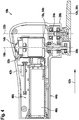
- FIG. 1 shows a side view of a portable power tool 10a.
- FIG. 2 shows a side sectional view of the machine tool 10a FIG. 1 ,
- the machine tool 10a is in the in FIG. 1 illustrated embodiment as a grinding machine, in particular as a delta sander formed. However, it is also conceivable for the machine tool 10a to have another configuration that appears appropriate to a person skilled in the art.
- the machine tool 10a is designed as an electrically driven machine tool 10a.
- the machine tool 10a is battery operated. Alternatively or additionally, it is conceivable that the machine tool 10a can be operated by cable.
- the machine tool 10a has a battery holder 40a, which is arranged in a housing 42a of the machine tool 10a.
- the housing 42a is designed in particular as a shell housing.
- the battery holder 40a is arranged at least substantially in a handle 44a of the machine tool 10a.
- the battery holder 40a is provided to receive a battery 46a for operation of the machine tool 10a.
- the battery 46a preferably has only one battery cell.
- the battery 46a has a maximum volume of 0.9 l, preferably of not more than 0.7 l and more preferably of not more than 0.5 l.
- the battery 46a has an electrical output power of at least 50 W, preferably at least 75 W and particularly preferably at least 100 W.
- the machine tool 10a has, in particular, a mass which, in particular including the battery 46a, is smaller than 700 g, preferably smaller than 600 g and particularly preferably smaller than 500 g.
- the machine tool 10a has a nominal power of at least 50 W, preferably at least 75 W, and particularly preferably at least 100 W.
- the machine tool 10a has an oscillating drivable tool holder 12a.
- the tool holder 12a is formed as a grinding plate 38a.
- the tool holder 12a is provided to receive an insert tool, in particular an abrasive sheet from an operator in a re-releasable manner.
- FIG. 3 shows a plan view of an underside of the tool holder 12a.
- the machine tool 10a has a drive unit 14a for driving the tool holder 12a.
- the drive unit 14a has an electric motor 52a, which is provided to convert electrical energy provided by the battery 46a into kinetic energy, in particular rotational energy.
- the drive unit 14a has a drive shaft 16a with a drive shaft 18a intersecting the tool holder 12a to drive at least the tool holder 12a.
- the drive shaft 16a is in particular at least partially formed by an armature shaft 54a of the electric motor 52a.
- the machine tool 10a comprises a bearing unit 20a for movably supporting the tool receptacle 12a about a bearing axis 22a of the bearing unit 20a, which cuts the tool receptacle 12a.
- the bearing unit 20a is provided in particular for movably supporting the tool holder 12a relative to the housing 42a of the machine tool 10a.
- the drive unit 14a is arranged inside the housing 42a in front of the storage unit 20a.
- the drive shaft 18a is formed differently from the bearing shaft 22a.
- the bearing axis 22a and the drive shaft 18a extend at least substantially spatially spaced from each other.
- the bearing axis 22a extends in particular exclusively along at least one component of the bearing unit 20a.
- the drive axle 18a runs in particular exclusively along at least one component of the drive unit 14a, in particular along the drive shaft 16a.
- the drive axle 18a extends at least substantially along the drive shaft 16a, in particular along the armature shaft 54a of the electric motor 52a.
- the drive axle 18a extends at least substantially parallel to the bearing axle 22a.
- the bearing axis 22a cuts the tool holder 12a offset from the drive shaft 18a.
- the bearing axis 22a cuts the tool holder 12a at least essentially in the middle.
- the bearing shaft 22a and the drive shaft 18a intersect the tool holder 12a in two spatially spaced intersection points 56a, 58a.
- the drive shaft 18a cuts the tool holder 12a at an intersection point 56a, which lies on a circle 60a enclosing the point of intersection 58a between the bearing axis 22a and the tool holder 12a.
- the drive shaft 18a intersects the tool holder 12a at an intersection 56a between the circle 60a enclosing the intersection 58a between the bearing shaft 22a and the tool holder 12a and a main extension direction 62a of the machine tool 10a.
- the drive shaft 18a cuts the tool holder 12a in front of the bearing axis 22a.
- the bearing unit 20a has a bearing pin 24a extending along the bearing axis 22a, on which the tool holder 12a is rotatably mounted about the bearing axis 22a.
- the bearing pin 24a is at least substantially cylindrical.
- the bearing pin 24a is in particular at least non-positively formed with the housing 42a of the machine tool 10a.
- the bearing pin 24a may be formed integrally with the housing 42a of the machine tool 10a.
- the bearing axis 22a extends in particular at least substantially along a main extension direction of the journal 24a.
- the bearing unit 20a further comprises a radial bearing 26a, which is provided for a rotatable mounting of the tool holder 12a about the bearing axis 22a.
- the radial bearing 26a is arranged on the bearing pin 24a.
- the radial bearing 26a is designed as a roller bearing, in particular as a ball bearing.
- the radial bearing 26a may be connected by means of an interference fit with the bearing pin 24a.
- the tool holder 12a has a receptacle 34a, which is provided for receiving the radial bearing 26a.
- the drive unit 14a has a rolling bearing 28a arranged eccentrically to the drive axle 18a on the drive shaft 16a.
- the rolling bearing 28a is designed in particular as a ball bearing.
- the rolling bearing 28a is provided to transmit a movement from the drive shaft 16a to the tool holder 12a.
- the tool holder 12a has two running surfaces 30a, 32a, which are provided, a movement of the rolling bearing 28a in a pendulum motion 36a of the tool holder 12a to transfer about the bearing axis 22a.
- the running surfaces 30a, 32a are in particular formed integrally with the tool holder 12a.
- the running surfaces 30a, 32a in particular run at least substantially parallel to one another.
- the rolling bearing 28a describes during a rotation of the drive shaft 16a an eccentric movement about the drive shaft 18a.
- the eccentric to the drive shaft 18a disposed on the drive shaft 16a roller bearing 28a is provided during rotation of the drive shaft 16a to apply the treads 30a, 32a alternately with a force.
- the mutual loading of the running surfaces 30a, 32a is intended to put the tool holder 12a in a pendulum motion 36a about the bearing axis 22a. Due to the central mounting of the tool holder 12a and the off-center drive no vibration elements are necessary.
- the tool holder 12a is excited in a pendulum fashion, whereby tips 64a of the tool holder 12a describe a long way despite small eccentricity. As a result, a high removal during grinding can be achieved at the edge of the tool holder 12a.
- FIGS. 4 and 5 a further embodiment of the invention is shown.
- the following descriptions and the drawings are essentially limited to the differences between the exemplary embodiments, with reference in principle to the same reference components, in particular with respect to components with the same reference numerals, to the drawings and / or the description of the other embodiments, in particular FIGS. 1 to 3 , can be referenced.
- To distinguish the embodiments of the letter a is the reference numerals of the embodiment in the FIGS. 1 to 3 readjusted.
- the letter a is replaced by the letter b.
- FIG. 4 shows a side sectional view of an alternative machine tool 10b.
- the machine tool 10b is in the in FIG. 4 illustrated embodiment as a grinding machine, in particular as a delta sander formed. However, it is also conceivable for the machine tool 10b to have another configuration that appears appropriate to a person skilled in the art.
- the machine tool 10b is designed as an electrically driven machine tool 10b.
- the machine tool 10b is battery operated. Alternatively or In addition, it is conceivable that the machine tool 10b can be operated by cable.
- the machine tool 10b has a battery receptacle 40b, which is arranged in a housing 42b of the machine tool 10b.
- the housing 42b is designed in particular as a shell housing.
- the battery holder 40b is arranged at least substantially in a handle 44b of the machine tool 10b.
- the battery receptacle 40b is provided to receive a battery 46b for operation of the machine tool 10a.
- the machine tool 10b has an oscillating drivable tool holder 12b.
- the tool holder 12b is formed as a grinding plate 38b.
- the tool holder 12b is provided to receive an insert tool, in particular an abrasive sheet from an operator in a detachable manner.
- FIG. 5 shows a plan view of an underside of the tool holder 12b.
- the machine tool 10b has a drive unit 14b for driving the tool holder 12b.
- the drive unit 14b has an electric motor 52b, which is provided to convert electrical energy provided by the battery 46b into kinetic energy, in particular rotational energy.
- the drive unit 14b has a drive shaft 16b with a drive shaft 18b which cuts the tool holder 12b to drive at least the tool holder 12b.
- the drive shaft 16b is in particular at least partially formed by an armature shaft 54b of the electric motor 52b.
- the machine tool 10b comprises a bearing unit 20b for a movable mounting of the tool holder 12b about a bearing axis 22b of the bearing unit 20b, which cuts the tool holder 12b.
- the bearing unit 20b is provided in particular for movably supporting the tool holder 12b relative to the housing 42b of the machine tool 10b.
- the drive unit 14b is disposed inside the housing 42b behind the storage unit 20b.
- the drive shaft 18b is formed differently from the bearing shaft 22b.
- the bearing axis 22b and the drive axle 18b extend at least substantially spatially spaced from each other.
- the bearing axis 22b extends in particular exclusively along at least one component of the bearing unit 20b.
- the drive axle 18b extends in particular exclusively along at least one component of the drive unit 14b, in particular along the drive shaft 16b.
- the drive axle 18b extends at least substantially along the drive shaft 16b, in particular along the armature shaft 54b of the electric motor 52b.
- the drive axle 18b extends at least substantially parallel to the bearing axle 22b.
- the bearing axis 22b cuts the tool holder 12b offset to the drive axis 18b.
- the bearing axis 22b cuts the tool holder 12b at least substantially in the center.
- the bearing shaft 22b and the drive shaft 18a intersect the tool holder 12b in two spatially spaced intersection points 56b, 58b.
- the drive shaft 18b intersects the tool holder 12b at an intersection point 56b, which lies on a circle 60b enclosing the point of intersection 58b between the bearing axis 22b and the tool holder 12b.
- the drive shaft 18b intersects the tool holder 12a at an intersection 56b between the circle 60b enclosing the intersection 58a between the bearing shaft 22b and the tool holder 12b and a main extension direction 62b of the machine tool 10b.
- the drive shaft 18b cuts the tool holder 12a behind the bearing axis 22b.
- the bearing unit 20b has a bearing pin 24b extending along the bearing axis 22b, on which the tool holder 12b is rotatably mounted about the bearing axis 22b.
- the bearing pin 24b is at least substantially cylindrical.
- the bearing pin 24b is in particular at least frictionally formed with the housing 42b of the machine tool 10b.
- the bearing pin 24b may be formed integrally with the housing 42b of the machine tool 10b.
- the bearing axis 22b extends in particular at least substantially along a main extension direction of the journal 24b.
- the drive unit 14b has a rolling bearing 28b arranged eccentrically to the drive axle 18b on the drive shaft 16b.
- the rolling bearing 28b is designed in particular as a ball bearing.
- the rolling bearing 28b is provided to transmit a movement from the drive shaft 16b to the tool holder 12b.
- the tool holder 12b has two running surfaces 30b, 32b, which are provided to transfer a movement of the roller bearing 28b into a pendulum movement 36b of the tool holder 12b about the bearing axis 22b.
- the running surfaces 30b, 32b are in particular formed integrally with the tool holder 12b.
- the running surfaces 30b, 32b in particular run at least substantially parallel to one another.
- the rolling bearing 28b describes during a rotation of the drive shaft 16b an eccentric movement about the drive axis 18b.
- the eccentric to the drive shaft 18b disposed on the drive shaft 16b roller bearing 28b is provided during rotation of the drive shaft 16b to apply the treads 30b, 32b alternately with a force.
- the mutual loading of the running surfaces 30b, 32b is intended to put the tool holder 12b in a pendulum movement 36b about the bearing axis 22b.
Abstract
Die Erfindung geht aus von einer tragbaren Werkzeugmaschine, insbesondere einer Schleifmaschine, mit zumindest einer oszillierend antreibbaren Werkzeugaufnahme (12a; 12b), mit zumindest einer Antriebseinheit (14a; 14b), welche zumindest eine Antriebswelle (16a; 16b) mit zumindest einer die Werkzeugaufnahme (12a; 12b) schneidenden Antriebsachse (18a; 18b) zu einem Antrieb zumindest der Werkzeugaufnahme (12a; 12b) aufweist, und mit zumindest einer Lagereinheit (20a; 20b) zu einer beweglichen Lagerung der Werkzeugaufnahme (12a; 12b) um eine Lagerachse (22a; 22b) der Lagereinheit (20a; 20b), die die Werkzeugaufnahme (12a; 12b) schneidet. Es wird vorgeschlagen, dass die Antriebsachse (18a; 18b) verschieden von der Lagerachse (22a; 22b) ausgebildet ist.The invention is based on a portable machine tool, in particular a grinding machine, with at least one oscillatingly drivable tool holder (12a, 12b), with at least one drive unit (14a, 14b) having at least one drive shaft (16a; 12a, 12b) for driving at least the tool holder (12a, 12b), and with at least one bearing unit (20a, 20b) for movably supporting the tool holder (12a, 12b) about a bearing axis (22a 22b) of the bearing unit (20a; 20b) which cuts the tool holder (12a; 12b). It is proposed that the drive axle (18a, 18b) is designed differently from the bearing axle (22a, 22b).
Description
Es ist bereits eine tragbare Werkzeugmaschine, insbesondere Schleifmaschine, mit zumindest einer oszillierend antreibbaren Werkzeugaufnahme, mit zumindest einer Antriebseinheit, welche zumindest eine Antriebswelle mit zumindest einer die Werkzeugaufnahme schneidenden Antriebsachse zu einem Antrieb zumindest der Werkzeugaufnahme aufweist, und mit zumindest einer Lagereinheit zu einer beweglichen Lagerung der Werkzeugaufnahme um eine Lagerachse der Lagereinheit, die die Werkzeugaufnahme schneidet, bekannt.It is already a portable machine tool, in particular grinding machine, with at least one oscillating drivable tool holder, with at least one drive unit which has at least one drive shaft with at least one drive shaft cutting the tool holder to a drive at least the tool holder, and with at least one storage unit to a movable storage the tool holder about a bearing axis of the bearing unit, which cuts the tool holder known.
Die Erfindung geht aus von einer tragbare Werkzeugmaschine, insbesondere Schleifmaschine, mit zumindest einer oszillierend antreibbaren Werkzeugaufnahme, mit zumindest einer Antriebseinheit, welche zumindest eine Antriebswelle mit zumindest einer die Werkzeugaufnahme schneidenden Antriebsachse zu einem Antrieb zumindest der Werkzeugaufnahme aufweist, und mit zumindest einer Lagereinheit zu einer beweglichen Lagerung der Werkzeugaufnahme um eine Lagerachse der Lagereinheit, die die Werkzeugaufnahme schneidet.The invention relates to a portable machine tool, in particular grinding machine, with at least one oscillating drivable tool holder, with at least one drive unit, which has at least one drive shaft with at least one drive shaft cutting the tool holder to a drive at least the tool holder, and at least one bearing unit to a movable mounting of the tool holder about a bearing axis of the bearing unit, which cuts the tool holder.
Es wird vorgeschlagen, dass die Antriebsachse verschieden von der Lagerachse ausgebildet ist.It is proposed that the drive axle is formed differently from the bearing axle.
Unter einer "tragbaren Werkzeugmaschine" soll hier insbesondere eine Werkzeugmaschine zu einer Bearbeitung von Werkstücken verstanden werden, die von einem Bediener transportmaschinenlos transportiert werden kann. Insbesondere ist die Werkzeugmaschine als eine elektrisch betriebene Werkzeugmaschine ausgebildet. Die Werkzeugmaschine ist insbesondere als eine netzbetriebene Werkzeugmaschine und/oder vorzugsweise als eine akkubetriebene Werkzeugmaschine ausgebildet. Insbesondere weist die Werkzeugmaschine eine Akkuaufnahme auf, welche dazu vorgesehen ist, einen Akku zu einem Betrieb der Werkzeugmaschine aufzunehmen. Insbesondere ist die Akkuaufnahme zumindest im Wesentlichen in einem Handgriff der Werkzeugmaschine angeordnet. Insbesondere weist der Akku zum Betrieb der Werkzeugmaschine lediglich eine Akkuzelle auf. Der Akku weist insbesondere ein Volumen von maximal 0,9 l, vorzugsweise von maximal 0,7 l und besonders bevorzugt von maximal 0,5 l auf. Insbesondere weist der Akku eine elektrische Ausgangsleistung von zumindest 50 W, vorzugsweise von zumindest 75 W und besonders bevorzugt von zumindest 100 W auf. Die tragbare Werkzeugmaschine weist insbesondere eine Masse auf, die, insbesondere inklusive Akku, kleiner ist als 700 g, bevorzugt kleiner ist als 600 g und besonders bevorzugt kleiner ist als 500 g. Insbesondere weist die Werkzeugmaschine eine Nennleistung von zumindest 50 W, vorzugsweise von zumindest 75 W und besonders bevorzugt von zumindest 100 W auf. Insbesondere liegt ein Verhältnis zwischen einer Grifffläche und einer Gesamtoberfläche der Werkzeugmaschine zwischen 0,4 und 0,9, bevorzugt aber zwischen 0,5 und 0,75. Bevorzugt ist die Werkzeugmaschine als Deltaschleifer, Schwingschleifer oder Multischleifer ausgebildet.A "portable machine tool" is to be understood here in particular as a machine tool for machining workpieces which can be transported without transport machine by an operator. In particular, the machine tool is designed as an electrically operated machine tool. The machine tool is designed in particular as a mains-operated machine tool and / or preferably as a battery-operated machine tool. In particular, the machine tool has a battery mount, which is provided to receive a battery for operation of the machine tool. In particular, the battery holder is arranged at least substantially in a handle of the machine tool. In particular, the battery for operating the machine tool only has a battery cell. In particular, the battery has a volume of at most 0.9 l, preferably of not more than 0.7 l and particularly preferably of not more than 0.5 l. In particular, the battery has an electrical output power of at least 50 W, preferably at least 75 W, and particularly preferably at least 100 W. In particular, the portable power tool has a mass which, in particular including the battery, is smaller than 700 g, preferably smaller than 600 g and particularly preferably smaller than 500 g. In particular, the machine tool has a nominal power of at least 50 W, preferably of at least 75 W and particularly preferably of at least 100 W. In particular, a ratio between a gripping surface and a total surface of the machine tool is between 0.4 and 0.9, but preferably between 0.5 and 0.75. Preferably, the machine tool is designed as a delta sander, orbital sander or multi-sander.
Unter einer "Antriebseinheit" in diesem Zusammenhang soll insbesondere eine Einheit verstanden werden, welche dazu vorgesehen ist, insbesondere elektrische Energie in kinetische Energie, insbesondere Rotationsenergie, umzuwandeln. Die Antriebseinheit weist insbesondere zumindest einen Elektromotor auf. Eine Antriebswelle der Antriebseinheit ist insbesondere zumindest teilweise von einer Ankerwelle des Elektromotors gebildet. Unter "vorgesehen" soll insbesondere speziell ausgelegt, speziell programmiert und/oder speziell ausgestattet verstanden werden. Darunter, dass ein Element und/oder eine Einheit zu einer bestimmten Funktion vorgesehen ist, soll insbesondere verstanden werden, dass das Element und/oder die Einheit diese bestimmte Funktion in zumindest einem Anwendungs- und/oder Betriebszustand erfüllen/erfüllt und/oder ausführen/ausführt. Unter einer "Werkzeugaufnahme" soll insbesondere ein Mittel zur Kopplung mit einer Antriebswelle verstanden werden, wie insbesondere eine Werkzeugaufnahme, an der beispielsweise eine Schleifplatte befestigbar ist, wie dies bei einem Deltaschleifer häufig der Fall ist, oder auch eine Schleifplatte selbst, die direkt an der Antriebswelle befestigt werden kann, wie dies häufig bei Handwerkzeugmaschinen mit einem oszillierenden Antrieb der Fall ist, und an der ein Schleifblatt befestigbar ist. Bevorzugt ist die Werkzeugaufnahme dazu vorgesehen, das Einsatzwerkzeug, insbesondere ein Schleifblatt von einem Bediener auf eine wieder lösbare Weise aufzunehmen. Eine zumindest im Wesentlichen entlang der Antriebswelle der Antriebseinheit, insbesondere entlang einer Ankerwelle eines Elektromotors der Antriebseinheit, verlaufende Antriebsachse schneidet die Werkzeugaufnahme zumindest im Wesentlichen senkrecht. Der Ausdruck "im Wesentlichen senkrecht" soll hier insbesondere eine Ausrichtung einer Richtung relativ zu einer Bezugsrichtung definieren, wobei die Richtung und die Bezugsrichtung, insbesondere in einer Ebene betrachtet, einen Winkel von 90° einschließen und der Winkel eine maximale Abweichung von insbesondere kleiner als 10°, vorteilhaft kleiner als 5° und besonders vorteilhaft kleiner als 2° aufweist.A "drive unit" in this context is to be understood in particular as a unit which is intended to convert, in particular, electrical energy into kinetic energy, in particular rotational energy. The drive unit has in particular at least one electric motor. A drive shaft of the drive unit is in particular at least partially formed by an armature shaft of the electric motor. "Provided" is to be understood in particular to be specially designed, specially programmed and / or specially equipped. By providing an element and / or a unit for a specific function, it should be understood in particular that the element and / or the unit fulfill / fulfill and / or execute this specific function in at least one application and / or operating state. performs. Under a "tool holder" is intended in particular a means for Coupling with a drive shaft are understood, in particular a tool holder, on which, for example, a grinding plate can be fastened, as is often the case with a delta sander, or even a grinding plate itself, which can be attached directly to the drive shaft, as is often the case with power tools with an oscillating drive is the case, and to which an abrasive sheet is fastened. Preferably, the tool holder is provided to receive the insert tool, in particular an abrasive sheet by an operator in a re-releasable manner. An at least substantially along the drive shaft of the drive unit, in particular along an armature shaft of an electric motor of the drive unit, extending drive shaft intersects the tool holder at least substantially perpendicular. The term "substantially perpendicular" is intended here to define, in particular, an orientation of a direction relative to a reference direction, the direction and the reference direction, in particular in one plane, including an angle of 90 ° and the angle a maximum deviation of, in particular, less than 10 °, advantageously less than 5 ° and particularly advantageously less than 2 °.
Unter einer "Lagereinheit" soll in diesem Zusammenhang insbesondere eine Einheit verstanden werden, die zumindest zwei Bauteile beweglich zueinander lagert. Die Lagereinheit ist insbesondere dazu vorgesehen, die Werkzeugaufnahme relativ zu einem Gehäuse der Werkzeugmaschine beweglich zu lagern. Insbesondere ist die Lagereinheit als eine Radiallagereinheit ausgebildet. Die Lagereinheit kann insbesondere als eine Gleitlager- und/oder Wälzlagereinheit ausgebildet sein. Insbesondere ist die Lagereinheit dazu vorgesehen, die Werkzeugaufnahme drehbar um eine Lagerachse zu lagern. Die Antriebseinheit ist insbesondere dazu vorgesehen, die Werkzeugaufnahme oszillierend um eine Lagerachse der Lagereinheit anzutreiben. Eine Lagerachse der Lagereinheit schneidet die Werkzeugaufnahme zumindest im Wesentlichen senkrecht.In this context, a "storage unit" is to be understood as meaning, in particular, a unit which supports at least two components movable relative to one another. The bearing unit is in particular provided for movably supporting the tool holder relative to a housing of the machine tool. In particular, the bearing unit is designed as a radial bearing unit. The bearing unit can be designed in particular as a sliding bearing and / or roller bearing unit. In particular, the bearing unit is provided to support the tool holder rotatably about a bearing axis. The drive unit is in particular provided to oscillate the tool holder about a bearing axis of the bearing unit. A bearing axis of the bearing unit cuts the tool holder at least substantially vertically.
Darunter, dass die Antriebsachse verschieden von der Lagerachse ausgebildet ist, soll in diesem Zusammenhang insbesondere verstanden werden, dass die Lagerachse und die Antriebsachse von zwei separaten Bauteilen gebildet sind. Insbesondere sind die Antriebsachse und die Lagerachse von zwei räumlich voneinander beabstandet angeordneten Bauteilen gebildet. Die Lagerachse und die Antriebsachse verlaufen zumindest im Wesentlichen räumlich beabstandet voneinander. Die Lagerachse verläuft insbesondere ausschließlich von zumindest entlang eines Bauteils der Lagereinheit. Die Antriebsachse verläuft insbesondere ausschließlich zumindest entlang eines Bauteils der Antriebseinheit, insbesondere entlang der Antriebswelle der Antriebseinheit. Insbesondere verläuft die Lagerachse entlang eines Bauteils der Lagereinheit, welches keinen unmittelbaren physikalischen Kontakt, insbesondere einen Stoffschluss und/oder Kraftschluss, mit einem Bauteil der Antriebseinheit, insbesondere der Antriebswelle der Antriebseinheit, hat, welches die Antriebsachse ausbildet.Including that the drive shaft is formed differently from the bearing axis should be understood in this context in particular, that the bearing axis and the drive shaft are formed by two separate components. In particular, the drive axle and the bearing axle are formed by two components spaced apart from one another. The bearing axis and the drive axis extend at least substantially spatially spaced from each other. The bearing axis runs in particular exclusively from at least along a component of the bearing unit. The drive axle extends in particular exclusively along at least one component of the drive unit, in particular along the drive shaft of the drive unit. In particular, the bearing axis runs along a component of the bearing unit, which has no direct physical contact, in particular an adhesion and / or adhesion, with a component of the drive unit, in particular the drive shaft of the drive unit, which forms the drive axle.
Durch eine derartige Ausgestaltung kann eine gattungsgemäße Werkzeugmaschine mit vorteilhaften konstruktiven Eigenschaften und/oder vorteilhaften Betriebseigenschaften bereitgestellt werden. Insbesondere kann durch die getrennte Ausbildung von einer Lagerachse in einer Antriebsachse ein vorteilhafter pendelnd oszillierender Antrieb der Werkzeugaufnahme um die Lagerachse erfolgen.Such a configuration can provide a generic machine tool with advantageous structural properties and / or advantageous operating properties. In particular, can be done by the separate training of a bearing axis in a drive axle, a more advantageous oscillating oscillating drive the tool holder to the bearing axis.
Ferner wird vorgeschlagen, dass die Lagerachse die Werkzeugaufnahme versetzt zu der Antriebsachse schneidet. Insbesondere schneiden die Lagerachse und die Antriebsachse die Werkzeugaufnahme in zwei räumlich voneinander beabstandeten Schnittpunkten. Insbesondere kann die Antriebsachse die Werkzeugaufnahme in einem Schnittpunkt, welcher auf einem den Schnittpunkt zwischen der Lagerachse und der Werkzeugaufnahme umschließenden Kreis liegt, schneiden. Insbesondere kann der den Schnittpunkt zwischen der Lagerachse und der Werkzeugaufnahme umschließende Kreis einen zumindest im Wesentlichen beliebigen Radius aufweisen. Insbesondere bildet der Schnittpunkt zwischen der Lagerachse und der Werkzeugaufnahme zumindest im Wesentlichen einen Mittelpunkt des Kreises, auf welchem der Schnittpunkt zwischen der Antriebsachse und der Werkzeugaufnahme liegt. Vorzugsweise schneidet die Antriebsachse die Werkzeugaufnahme entlang einer Hauptarbeitsrichtung der Werkzeugmaschine betrachtet in einem Schnittpunkt, welcher vor oder hinter einem Schnittpunkt zwischen der Lagerachse und der Werkzeugaufnahme liegt. Insbesondere schneidet die Antriebsachse die Werkzeugaufnahme in einem Schnittpunkt zwischen dem den Schnittpunkt zwischen der Lagerachse und der Werkzeugaufnahme umschließenden Kreis und einer Haupterstreckungsrichtung der Werkzeugmaschine. Hierdurch kann ein vorteilhafter Antrieb der Werkzeugaufnahme und/oder eine vorteilhafte Anordnung der Werkzeugaufnahme an einem Grundgehäuse der Werkzeugmaschine ermöglicht werden. Durch die versetzte Anordnung der Lagerachse und der Antriebsachse kann auf eine Verwendung von Schwingelementen vorteilhaft verzichtet werden.It is also proposed that the bearing axis offset the tool holder offset to the drive axle. In particular, the bearing axis and the drive axis cut the tool holder in two spatially spaced intersections. In particular, the drive axle can cut the tool receptacle at an intersection which lies on a circle enclosing the point of intersection between the bearing axis and the tool receptacle. In particular, the circle enclosing the point of intersection between the bearing axis and the tool holder can have an at least essentially arbitrary radius. In particular, the point of intersection between the bearing axis and the tool holder at least substantially forms a center of the circle on which lies the point of intersection between the drive axis and the tool holder. Preferably, the drive shaft cuts the tool holder along a main working direction of the machine tool viewed in an intersection, which lies in front of or behind an intersection between the bearing axis and the tool holder. In particular, the drive shaft intersects the tool holder in an intersection between the circle enclosing the intersection between the bearing axis and the tool holder and a main extension direction of the machine tool. This allows an advantageous drive of the tool holder and / or an advantageous arrangement of the tool holder are made possible on a base housing of the machine tool. Due to the staggered arrangement of the bearing axis and the drive axle can be advantageously dispensed with a use of vibrating elements.
Des Weiteren wird vorgeschlagen, dass die Antriebsachse zumindest im Wesentlichen parallel versetzt zu der Lagerachse verläuft. Unter "im Wesentlichen parallel" soll hier insbesondere eine Ausrichtung einer Richtung relativ zu einer Bezugsrichtung, insbesondere in einer Ebene, verstanden werden, wobei die Richtung gegenüber der Bezugsrichtung eine Abweichung insbesondere kleiner als 10°, vorteilhaft kleiner als 5° und besonders vorteilhaft kleiner als 2° aufweist. Hierdurch kann eine vorteilhafte Anordnung und/oder ein vorteilhafter Verlauf der Lagerachse und der Antriebsachse insbesondere innerhalb der Werkzeugmaschine erreicht werden.Furthermore, it is proposed that the drive axle extends at least substantially offset parallel to the bearing axis. "Substantially parallel" is to be understood here as meaning in particular an alignment of a direction relative to a reference direction, in particular in a plane, wherein the direction relative to the reference direction is a deviation, in particular less than 10 °, advantageously less than 5 ° and particularly advantageously less than 2 °. In this way, an advantageous arrangement and / or an advantageous course of the bearing axis and the drive axis can be achieved, in particular within the machine tool.
Ferner wird vorgeschlagen, dass die Lagerachse die Schleifplatte zumindest im Wesentlichen mittig schneidet. Darunter dass die die Lagerachse die Schleifplatte zumindest im Wesentlichen mittig schneidet, soll insbesondere verstanden werden, dass ein Schnittpunkt der Lagerachse mit der Werkzeugaufnahme zumindest im Wesentlichen identisch ist mit dem Mittelpunkt der Werkzeugaufnahme. Insbesondere weicht der Schnittpunkt der Lagerachse mit der Werkzeugaufnahme um maximal 5 mm, vorzugsweise um maximal 2 mm, vorteilhaft um maximal 1 mm und besonders bevorzugt um maximal 0,5 mm von dem Mittelpunkt der Werkzeugaufnahme ab. Durch die mittige Lagerung und den außermittigen Antrieb der Werkzeugaufnahme kann die Werkzeugaufnahme vorteilhaft ohne Schwingelemente pendelnd um die Lagerachse angetrieben werden.It is also proposed that the bearing axis intersects the grinding plate at least substantially in the center. By virtue of the fact that the bearing axis intersects the grinding plate at least substantially in the center, it should be understood in particular that an intersection of the bearing axis with the tool holder is at least substantially identical to the center of the tool holder. In particular, the intersection of the bearing axis with the tool holder differs by a maximum of 5 mm, preferably by a maximum of 2 mm, advantageously by a maximum of 1 mm and particularly preferably by a maximum of 0.5 mm from the center of the tool holder. Due to the central bearing and the eccentric drive of the tool holder, the tool holder can advantageously be driven without oscillating elements oscillating about the bearing axis.
Zudem wird vorgeschlagen, dass die Lagereinheit zumindest einen sich entlang der Lagerachse erstreckenden Lagerzapfen aufweist, an welchem die Werkzeugaufnahme um die Lagerachse drehbar befestigt ist. Insbesondere ist der Lagerzapfen zumindest im Wesentlichen zylindrisch ausgebildet. Der Lagerzapfen ist insbesondere zumindest kraftschlüssig mit einem Gehäuse der Werkzeugmaschine ausgebildet. Insbesondere kann der Lagerzapfen einstückig mit einem Gehäuse der Werkzeugmaschine ausgebildet sein. Unter "einstückig" soll insbesondere zumindest stoffschlüssig verbunden verstanden werden, beispielsweise durch einen Schweißprozess, einen Klebeprozess, einen Anspritzprozess und/oder einen anderen, dem Fachmann als sinnvoll erscheinenden Prozess, und/oder vorteilhaft in einem Stück geformt verstanden werden, wie beispielsweise durch eine Herstellung aus einem Guss und/oder durch eine Herstellung in einem Ein- oder Mehrkomponentenspritzverfahren und vorteilhaft aus einem einzelnen Rohling. Die Lagerachse erstreckt sich insbesondere zumindest im Wesentlichen entlang einer Haupterstreckungsrichtung des Lagerzapfens. Vorzugsweise weist die Lagereinheit zumindest ein Radiallager auf, welches zu einer drehbaren Lagerung der Schleifplatte um die Lagerachse vorgesehen ist. Insbesondere ist das Radiallager zumindest teilweise und vorzugsweise vollständig an dem Lagerzapfen angeordnet. Das Radiallager kann insbesondere als ein Gleitlager und/oder vorzugsweise als ein Wälzlager, insbesondere als ein Kugellager, ausgebildet sein. Insbesondere kann das Radiallager mittels eines Presssitzes mit dem Lagerzapfen verbunden sein. Insbesondere weist die Werkzeugaufnahme zumindest eine Aufnahme auf, welche dazu vorgesehen ist, das Radiallager der Lagereinheit zumindest teilweise aufzunehmen. Hierdurch kann die Werkzeugaufnahme vorteilhaft einfach und/oder zuverlässig drehbar um die Lagerachse an der Werkzeugmaschine befestigt werden.In addition, it is proposed that the bearing unit has at least one bearing journal extending along the bearing axis, on which the tool receptacle is rotatably mounted about the bearing axis. In particular, the bearing pin is at least substantially cylindrical. The bearing pin is in particular at least frictionally formed with a housing of the machine tool. In particular, the bearing journal can be formed integrally with a housing of the machine tool. By "one piece" should be understood in particular at least materially connected connected, for example by a welding process, a gluing process, an injection process and / or another process which appears expedient to the person skilled in the art, and / or advantageously shaped in one piece, for example by production from a cast and / or by production in an on or multi-component injection molding and advantageously from a single blank. The bearing axis extends in particular at least substantially along a main extension direction of the bearing journal. Preferably, the bearing unit has at least one radial bearing, which is provided for a rotatable mounting of the grinding plate about the bearing axis. In particular, the radial bearing is at least partially and preferably arranged completely on the bearing journal. The radial bearing may in particular be designed as a plain bearing and / or preferably as a roller bearing, in particular as a ball bearing. In particular, the radial bearing can be connected by means of a press fit with the bearing pin. In particular, the tool holder has at least one receptacle which is provided to at least partially accommodate the radial bearing of the bearing unit. As a result, the tool holder can advantageously be easily and / or reliably mounted rotatable about the bearing axis on the machine tool.
Ferner wird vorgeschlagen, dass die Antriebseinheit ein exzentrisch zur Antriebsachse an der Antriebswelle angeordnetes Wälzlager aufweist, welches dazu vorgesehen ist, eine Bewegung von der Antriebswelle auf die Werkzeugaufnahme zu übertragen. Insbesondere ist das Wälzlager exzentrisch an der Antriebswelle angeordnet. Das Wälzlager beschreibt während einer Rotation der Antriebswelle insbesondere eine exzentrische Bewegung um die Antriebsachse. Insbesondere weist die Werkzeugaufnahme zumindest eine zu dem Wälzlager korrespondierende Lauffläche auf, über welche das Wälzlager die exzentrische um die Antriebsachse verlaufende Bewegung auf die Werkzeugaufnahme überträgt. Insbesondere weist die Werkzeugaufnahme zumindest eine Lauffläche auf, welche dazu vorgesehen ist, eine Bewegung des Wälzlagers in eine Pendelbewegung der Werkzeugaufnahme um die Lagerachse zu überführen. Insbesondere weist die Werkzeugaufnahme zumindest zwei Laufflächen auf, welche dazu vorgesehen sind, eine Bewegung des Wälzlagers in eine Pendelbewegung der Werkzeugaufnahme um die Lagerachse zu überführen. Insbesondere sind die Laufflächen einstückig mit der Werkzeugaufnahme ausgebildet. Die Laufflächen verlaufen insbesondere zumindest im Wesentlichen parallel zueinander. Das exzentrisch zur Antriebsachse an der Antriebswelle angeordnete Wälzlager ist insbesondere während einer Rotation der Antriebswelle dazu vorgesehen, die Laufflächen im Wechsel mit einer Kraft zu beaufschlagen. Insbesondere ist die wechselseitige Beaufschlagung der Laufflächen dazu vorgesehen, die Werkzeugaufnahme in eine Pendelbewegung zu versetzen. Hierdurch kann die Werkzeugaufnahme vorteilhaft einfach und/oder effizient in eine oszillierende Pendelbewegung um die Lagerachse versetzt werden. Durch die Pendelbewegung beschreiben Spitzen der Werkzeugaufnahme trotz kleiner Exzentrizität einen großen Weg. Hierdurch kann am Rand der Werkzeugaufnahme ein hoher Abtrag beim Schleifen erreicht werden.It is also proposed that the drive unit has an eccentric to the drive shaft arranged on the drive shaft bearings, which is intended to transmit a movement of the drive shaft to the tool holder. In particular, the rolling bearing is arranged eccentrically on the drive shaft. The rolling bearing describes during a rotation of the drive shaft in particular an eccentric movement about the drive axis. In particular, the tool holder has at least one running surface corresponding to the rolling bearing, via which the rolling bearing transmits the eccentric movement extending about the drive axis to the tool holder. In particular, the tool holder has at least one running surface, which is provided to transfer a movement of the rolling bearing into a pendulum movement of the tool holder about the bearing axis. In particular, the tool holder has at least two running surfaces, which are provided to transfer a movement of the rolling bearing into a pendulum movement of the tool holder about the bearing axis. In particular, the running surfaces are formed integrally with the tool holder. The treads in particular run at least substantially parallel to each other. The rolling bearing arranged eccentrically to the drive shaft on the drive shaft is provided in particular during a rotation of the drive shaft to act on the running surfaces alternately with a force. In particular, the mutual loading of the running surfaces is provided to enable the tool holder in a pendulum motion. As a result, the tool holder can advantageously be displaced easily and / or efficiently into an oscillating pendulum movement about the bearing axis. Due to the pendulum motion, tips of the tool holder describe a long way despite their small eccentricity. As a result, a high removal during grinding can be achieved at the edge of the tool holder.
Zudem wird eine Werkzeugaufnahme, insbesondere eine Schleifplatte für eine Werkzeugmaschine vorgeschlagen, wobei die Werkzeugaufnahme zumindest eine Aufnahme für ein Radiallager aufweist, welches zu einer drehbaren Lagerung der Werkzeugaufnahme um eine Lagerachse vorgesehen ist, und zumindest eine Lauffläche aufweist, welche dazu vorgesehen ist, eine Bewegung eines Wälzlagers in eine Pendelbewegung der Werkzeugaufnahme um die Lagerachse zu überführen. Hierdurch kann eine Werkzeugaufnahme mit vorteilhaften konstruktiven Eigenschaften und/oder vorteilhaften Betriebseigenschaften bereitgestellt werden. Insbesondere kann ein vorteilhafter pendelnd oszillierender Antrieb der Werkzeugaufnahme um die Lagerachse erfolgen. Ferner kann die Werkzeugaufnahme vorteilhaft ohne Schwingelemente pendelnd um die Lagerachse angetrieben werden.In addition, a tool holder, in particular a grinding plate for a machine tool is proposed, wherein the tool holder has at least one receptacle for a radial bearing, which is provided for a rotatable mounting of the tool holder about a bearing axis, and at least one tread, which is intended to a movement a rolling bearing in a pendulum movement of the tool holder to transfer the bearing axis. In this way, a tool holder can be provided with advantageous structural properties and / or advantageous operating characteristics. In particular, an advantageously oscillating oscillating drive of the tool holder can take place about the bearing axis. Furthermore, the tool holder can advantageously be driven oscillating about the bearing axis without oscillating elements.
Zudem wird ein Verfahren zu einem oszillierenden Antrieb einer Werkzeugaufnahme vorgeschlagen, bei welchem eine Bewegung eines exzentrisch zu einer Antriebsachse an einer Antriebswelle angeordneten Wälzlagers in eine Pendelbewegung der Werkzeugaufnahme um eine von der Antriebsachse verschiedene Lagerachse überführt wird. Insbesondere wird die Werkzeugaufnahme zumindest im Wesentlichen mittig drehbar um die Lagerachse gelagert. Das Wälzlager beschreibt während einer Rotation der Antriebswelle insbesondere eine exzentrische Bewegung um die Antriebswelle. Insbesondere wird eine exzentrische um die Antriebsachse verlaufende Bewegung des Wälzlagers über zumindest eine Lauffläche, vorzugsweise über zumindest zwei Laufflächen, auf die Werkzeugaufnahme übertragen. Insbesondere während einer Rotation der Antriebswelle werden die Laufflächen der Werkzeugaufnahme durch ein exzentrisch zur Antriebsachse an der Antriebswelle angeordnetes Wälzlager im Wechsel mit einer Kraft zu beaufschlagt. Insbesondere wird die Werkzeugaufnahme durch die wechselseitige Beaufschlagung der Laufflächen in eine oszillierende Pendelbewegung um die Lagerachse versetzt. Hierdurch kann die Werkzeugaufnahme vorteilhaft einfach und/oder effizient in eine oszillierende Pendelbewegung um die Lagerachse versetzt werden.In addition, a method for an oscillating drive of a tool holder is proposed, in which a movement of a roller bearing arranged eccentrically to a drive shaft on a drive shaft is converted into a pendulum movement of the tool holder about a bearing axis different from the drive axle. In particular, the tool holder is mounted at least substantially centrally rotatable about the bearing axis. The rolling bearing describes during a rotation of the drive shaft in particular an eccentric movement about the drive shaft. In particular, an eccentric movement of the rolling bearing running about the drive axis via at least one running surface, preferably via at least two running surfaces, on the tool holder transfer. In particular, during a rotation of the drive shaft, the running surfaces of the tool holder are acted upon by an eccentric to the drive shaft arranged on the drive shaft bearings alternately with a force. In particular, the tool holder is offset by the mutual application of the running surfaces in an oscillating pendulum motion about the bearing axis. As a result, the tool holder can advantageously be displaced easily and / or efficiently into an oscillating pendulum movement about the bearing axis.
Die erfindungsgemäße Werkzeugmaschine, die erfindungsgemäße Werkzeugaufnahme, und/oder das erfindungsgemäße Verfahren sollen/soll hierbei nicht auf die oben beschriebene Anwendung und Ausführungsform beschränkt sein. Insbesondere können/kann die erfindungsgemäße Werkzeugmaschine, die erfindungsgemäße Werkzeugaufnahme, und/oder das erfindungsgemäße Verfahren zu einer Erfüllung einer hierin beschriebenen Funktionsweise eine von einer hierin genannten Anzahl von einzelnen Elementen, Bauteilen und Einheiten sowie Verfahrensschritten abweichende Anzahl aufweisen. Zudem sollen bei den in dieser Offenbarung angegebenen Wertebereichen auch innerhalb der genannten Grenzen liegende Werte als offenbart und als beliebig einsetzbar gelten.The machine tool according to the invention, the tool holder according to the invention, and / or the method according to the invention should / should not be limited to the application and embodiment described above. In particular, the machine tool according to the invention, the tool holder according to the invention, and / or the method according to the invention for performing a function described herein can have a number deviating from a number of individual elements, components and units and method steps mentioned herein. In addition, in the value ranges indicated in this disclosure, values lying within the stated limits are also to be disclosed as disclosed and used as desired.
Weitere Vorteile ergeben sich aus der folgenden Zeichnungsbeschreibung. In der Zeichnung sind zwei Ausführungsbeispiele der Erfindung dargestellt. Die Zeichnung, die Beschreibung und die Ansprüche enthalten zahlreiche Merkmale in Kombination. Der Fachmann wird die Merkmale zweckmäßigerweise auch einzeln betrachten und zu sinnvollen weiteren Kombinationen zusammenfassen.Further advantages emerge from the following description of the drawing. In the drawing, two embodiments of the invention are shown. The drawing, the description and the claims contain numerous features in combination. The person skilled in the art will expediently also consider the features individually and combine them into meaningful further combinations.
Es zeigen:
- Fig. 1
- eine seitliche Ansicht einer als Deltaschleifer ausgebildeten tragbaren Werkzeugmaschine mit einer oszillierend antreibbaren Werkzeugaufnahme,
- Fig. 2
- eine seitliche Schnittansicht der tragbaren Werkzeugmaschine,
- Fig. 3
- eine Draufsicht auf eine Unterseite der Werkzeugaufnahme,
- Fig. 4
- eine seitliche Schnittansicht einer alternativen tragbaren Werkzeugmaschine und
- Fig. 5
- eine Draufsicht auf eine Unterseite einer Werkzeugaufnahme der Werkzeugmaschine gemäß
Figur 4 .
- Fig. 1
- a side view of a designed as a delta sander portable power tool with an oscillating drivable tool holder,
- Fig. 2
- a side sectional view of the portable power tool,
- Fig. 3
- a top view of an underside of the tool holder,
- Fig. 4
- a side sectional view of an alternative portable power tool and
- Fig. 5
- a plan view of an underside of a tool holder of the machine tool according to
FIG. 4 ,
Die Werkzeugmaschine 10a weist eine oszillierend antreibbare Werkzeugaufnahme 12a auf. Die Werkzeugaufnahme 12a ist als eine Schleifplatte 38a ausgebildet. Bevorzugt ist die Werkzeugaufnahme 12a dazu vorgesehen, ein Einsatzwerkzeug, insbesondere ein Schleifblatt von einem Bediener auf eine wieder lösbare Weise aufzunehmen.
Die Lagerachse 22a schneidet die Werkzeugaufnahme 12a versetzt zu der Antriebsachse 18a. Die Lagerachse 22a schneidet die Werkzeugaufnahme 12a zumindest im Wesentlichen mittig. Die Lagerachse 22a und die Antriebsachse 18a schneiden die Werkzeugaufnahme 12a in zwei räumlich voneinander beabstandeten Schnittpunkten 56a, 58a. Insbesondere schneidet die Antriebsachse 18a die Werkzeugaufnahme 12a in einem Schnittpunkt 56a, welcher auf einem den Schnittpunkt 58a zwischen der Lagerachse 22a und der Werkzeugaufnahme 12a umschließenden Kreis 60a liegt. Die Antriebsachse 18a schneidet die Werkzeugaufnahme 12a in einem Schnittpunkt 56a zwischen dem den Schnittpunkt 58a zwischen der Lagerachse 22a und der Werkzeugaufnahme 12a umschließenden Kreis 60a und einer Haupterstreckungsrichtung 62a der Werkzeugmaschine 10a. Die Antriebsachse 18a schneidet die Werkzeugaufnahme 12a vor der Lagerachse 22a.The bearing
Die Lagereinheit 20a weist einen sich entlang der Lagerachse 22a erstreckenden Lagerzapfen 24a auf, an welchem die Werkzeugaufnahme 12a um die Lagerachse 22a drehbar befestigt ist. Der Lagerzapfen 24a ist zumindest im Wesentlichen zylindrisch ausgebildet. Der Lagerzapfen 24a ist insbesondere zumindest kraftschlüssig mit dem Gehäuse 42a der Werkzeugmaschine 10a ausgebildet. Insbesondere kann der Lagerzapfen 24a einstückig mit dem Gehäuse 42a der Werkzeugmaschine 10a ausgebildet sein. Die Lagerachse 22a erstreckt sich insbesondere zumindest im Wesentlichen entlang einer Haupterstreckungsrichtung des Lagerzapfens 24a. Die Lagereinheit 20a umfasst ferner ein Radiallager 26a, welches zu einer drehbaren Lagerung der Werkzeugaufnahme 12a um die Lagerachse 22a vorgesehen ist. Das Radiallager 26a ist an dem Lagerzapfen 24a angeordnet. Das Radiallager 26a ist als ein Wälzlager, insbesondere als ein Kugellager, ausgebildet. Insbesondere kann das Radiallager 26a mittels eines Presssitzes mit dem Lagerzapfen 24a verbunden sein. Die Werkzeugaufnahme 12a weist eine Aufnahme 34a auf, welche zu einer Aufnahme des Radiallagers 26a vorgesehen ist.The
Die Antriebseinheit 14a weist ein exzentrisch zur Antriebsachse 18a an der Antriebswelle 16a angeordnetes Wälzlager 28a auf. Das Wälzlager 28a ist insbesondere als ein Kugellager ausgebildet. Das Wälzlager 28a ist dazu vorgesehen, eine Bewegung von der Antriebswelle 16a auf die Werkzeugaufnahme 12a zu übertragen. Die Werkzeugaufnahme 12a weist zwei Laufflächen 30a, 32a auf, welche dazu vorgesehen sind, eine Bewegung des Wälzlagers 28a in eine Pendelbewegung 36a der Werkzeugaufnahme 12a um die Lagerachse 22a zu überführen. Die Laufflächen 30a, 32a sind insbesondere einstückig mit der Werkzeugaufnahme 12a ausgebildet. Die Laufflächen 30a, 32a verlaufen insbesondere zumindest im Wesentlichen parallel zueinander. Das Wälzlager 28a beschreibt während einer Rotation der Antriebswelle 16a eine exzentrische Bewegung um die Antriebsachse 18a. Das exzentrisch zur Antriebsachse 18a an der Antriebswelle 16a angeordnete Wälzlager 28a ist während einer Rotation der Antriebswelle 16a dazu vorgesehen, die Laufflächen 30a, 32a im Wechsel mit einer Kraft zu beaufschlagen. Die wechselseitige Beaufschlagung der Laufflächen 30a, 32a ist dazu vorgesehen, die Werkzeugaufnahme 12a in eine Pendelbewegung 36a um die Lagerachse 22a zu versetzen. Durch die mittige Lagerung der Werkzeugaufnahme 12a und den außermittigen Antrieb sind keine Schwingelemente notwendig. Die Werkzeugaufnahme 12a wird pendelnd angeregt, wodurch Spitzen 64a der Werkzeugaufnahme 12a trotz kleiner Exzentrizität einen großen Weg beschreiben. Hierdurch kann am Rand der Werkzeugaufnahme 12a ein hoher Abtrag beim Schleifen erreicht werden.The
In den
Die Werkzeugmaschine 10b weist eine oszillierend antreibbare Werkzeugaufnahme 12b auf. Die Werkzeugaufnahme 12b ist als eine Schleifplatte 38b ausgebildet. Bevorzugt ist die Werkzeugaufnahme 12b dazu vorgesehen, ein Einsatzwerkzeug, insbesondere ein Schleifblatt von einem Bediener auf eine wieder lösbare Weise aufzunehmen.
Die Lagerachse 22b schneidet die Werkzeugaufnahme 12b versetzt zu der Antriebsachse 18b. Die Lagerachse 22b schneidet die Werkzeugaufnahme 12b zumindest im Wesentlichen mittig. Die Lagerachse 22b und die Antriebsachse 18a schneiden die Werkzeugaufnahme 12b in zwei räumlich voneinander beabstandeten Schnittpunkten 56b, 58b. Insbesondere schneidet die Antriebsachse 18b die Werkzeugaufnahme 12b in einem Schnittpunkt 56b, welcher auf einem den Schnittpunkt 58b zwischen der Lagerachse 22b und der Werkzeugaufnahme 12b umschließenden Kreis 60b liegt. Die Antriebsachse 18b schneidet die Werkzeugaufnahme 12a in einem Schnittpunkt 56b zwischen dem den Schnittpunkt 58a zwischen der Lagerachse 22b und der Werkzeugaufnahme 12b umschließenden Kreis 60b und einer Haupterstreckungsrichtung 62b der Werkzeugmaschine 10b. Die Antriebsachse 18b schneidet die Werkzeugaufnahme 12a hinter der Lagerachse 22b.The bearing
Die Lagereinheit 20b weist einen sich entlang der Lagerachse 22b erstreckenden Lagerzapfen 24b auf, an welchem die Werkzeugaufnahme 12b um die Lagerachse 22b drehbar befestigt ist. Der Lagerzapfen 24b ist zumindest im Wesentlichen zylindrisch ausgebildet. Der Lagerzapfen 24b ist insbesondere zumindest kraftschlüssig mit dem Gehäuse 42b der Werkzeugmaschine 10b ausgebildet. Insbesondere kann der Lagerzapfen 24b einstückig mit dem Gehäuse 42b der Werkzeugmaschine 10b ausgebildet sein. Die Lagerachse 22b erstreckt sich insbesondere zumindest im Wesentlichen entlang einer Haupterstreckungsrichtung des Lagerzapfens 24b.The
Die Antriebseinheit 14b weist ein exzentrisch zur Antriebsachse 18b an der Antriebswelle 16b angeordnetes Wälzlager 28b auf. Das Wälzlager 28b ist insbesondere als ein Kugellager ausgebildet. Das Wälzlager 28b ist dazu vorgesehen, eine Bewegung von der Antriebswelle 16b auf die Werkzeugaufnahme 12b zu übertragen. Die Werkzeugaufnahme 12b weist zwei Laufflächen 30b, 32b auf, welche dazu vorgesehen sind, eine Bewegung des Wälzlagers 28b in eine Pendelbewegung 36b der Werkzeugaufnahme 12b um die Lagerachse 22b zu überführen. Die Laufflächen 30b, 32b sind insbesondere einstückig mit der Werkzeugaufnahme 12b ausgebildet. Die Laufflächen 30b, 32b verlaufen insbesondere zumindest im Wesentlichen parallel zueinander. Das Wälzlager 28b beschreibt während einer Rotation der Antriebswelle 16b eine exzentrische Bewegung um die Antriebsachse 18b. Das exzentrisch zur Antriebsachse 18b an der Antriebswelle 16b angeordnete Wälzlager 28b ist während einer Rotation der Antriebswelle 16b dazu vorgesehen, die Laufflächen 30b, 32b im Wechsel mit einer Kraft zu beaufschlagen. Die wechselseitige Beaufschlagung der Laufflächen 30b, 32b ist dazu vorgesehen, die Werkzeugaufnahme 12b in eine Pendelbewegung 36b um die Lagerachse 22b zu versetzen.The
Claims (10)
Applications Claiming Priority (1)
| Application Number | Priority Date | Filing Date | Title |
|---|---|---|---|
| DE102016223508.7A DE102016223508A1 (en) | 2016-11-28 | 2016-11-28 | Portable machine tool |
Publications (2)
| Publication Number | Publication Date |
|---|---|
| EP3330044A1 true EP3330044A1 (en) | 2018-06-06 |
| EP3330044B1 EP3330044B1 (en) | 2023-08-16 |
Family
ID=60182430
Family Applications (1)
| Application Number | Title | Priority Date | Filing Date |
|---|---|---|---|
| EP17198177.2A Active EP3330044B1 (en) | 2016-11-28 | 2017-10-25 | Portable machine tool |
Country Status (3)
| Country | Link |
|---|---|
| EP (1) | EP3330044B1 (en) |
| CN (1) | CN108115621B (en) |
| DE (1) | DE102016223508A1 (en) |
Cited By (1)
| Publication number | Priority date | Publication date | Assignee | Title |
|---|---|---|---|---|
| WO2020136087A1 (en) * | 2018-12-27 | 2020-07-02 | Robert Bosch Gmbh | Hand-held power tool |
Citations (2)
| Publication number | Priority date | Publication date | Assignee | Title |
|---|---|---|---|---|
| EP2377647A1 (en) * | 2010-04-16 | 2011-10-19 | C. & E. Fein GmbH | Hand tool |
| JP5363870B2 (en) * | 2009-05-14 | 2013-12-11 | 日東工器株式会社 | Polishing device with eccentric rotational motion |
Family Cites Families (8)
| Publication number | Priority date | Publication date | Assignee | Title |
|---|---|---|---|---|
| JPH0634929Y2 (en) * | 1988-09-01 | 1994-09-14 | ヤスハラ株式会社 | Polishing equipment |
| DE4233728A1 (en) * | 1992-10-07 | 1994-04-14 | Bosch Gmbh Robert | Eccentric disc grinder |
| DE19546310A1 (en) * | 1995-12-12 | 1997-06-19 | Troeger Johannes Dr Ing Habil | Reduced-vibration linear super-finish grinder |
| DE19826340A1 (en) * | 1998-06-12 | 1999-12-16 | Bosch Gmbh Robert | Orbital sander with oscillating plate |
| DE102007018465A1 (en) * | 2007-04-19 | 2008-10-23 | Robert Bosch Gmbh | Motor driven machine tool |
| DE102007018464A1 (en) * | 2007-04-19 | 2008-10-23 | Robert Bosch Gmbh | Motor driven machine tool |
| WO2014023229A1 (en) * | 2012-08-07 | 2014-02-13 | 苏州宝时得电动工具有限公司 | Grinding power tool |
| DE102013100085A1 (en) * | 2013-01-07 | 2014-07-10 | C. & E. Fein Gmbh | Oscillating powered machine tool |
-
2016
- 2016-11-28 DE DE102016223508.7A patent/DE102016223508A1/en active Pending
-
2017
- 2017-10-25 EP EP17198177.2A patent/EP3330044B1/en active Active
- 2017-11-28 CN CN201711213239.7A patent/CN108115621B/en active Active
Patent Citations (2)
| Publication number | Priority date | Publication date | Assignee | Title |
|---|---|---|---|---|
| JP5363870B2 (en) * | 2009-05-14 | 2013-12-11 | 日東工器株式会社 | Polishing device with eccentric rotational motion |
| EP2377647A1 (en) * | 2010-04-16 | 2011-10-19 | C. & E. Fein GmbH | Hand tool |
Non-Patent Citations (2)
| Title |
|---|
| ANONYMOUS: "SKIL 7.2V Detail Sander (00024250001), Part #: 2425_Type_1", TOOLPARTS, 1 July 1996 (1996-07-01), pages 1 - 3, XP093043998 |
| ANONYMOUS: "Skil", WIKIPEDIA, 30 March 2021 (2021-03-30), pages 1 - 4, XP093043978 |
Cited By (2)
| Publication number | Priority date | Publication date | Assignee | Title |
|---|---|---|---|---|
| WO2020136087A1 (en) * | 2018-12-27 | 2020-07-02 | Robert Bosch Gmbh | Hand-held power tool |
| WO2020136086A1 (en) * | 2018-12-27 | 2020-07-02 | Robert Bosch Gmbh | Hand-held power tool |
Also Published As
| Publication number | Publication date |
|---|---|
| CN108115621B (en) | 2022-09-20 |
| CN108115621A (en) | 2018-06-05 |
| DE102016223508A1 (en) | 2018-05-30 |
| EP3330044B1 (en) | 2023-08-16 |
Similar Documents
| Publication | Publication Date | Title |
|---|---|---|
| EP2139647B1 (en) | Motor-driven machine tool | |
| EP2242613B1 (en) | Motor-driven machine tool | |
| DE102005007843A1 (en) | band saw | |
| DE102007018465A1 (en) | Motor driven machine tool | |
| DE102010042605A1 (en) | Work tool, in particular power tool | |
| WO2015015015A1 (en) | Assembly having a handheld power tool and a roughing disk | |
| WO2005053916A1 (en) | Cutting head for an electric hair cutting machine | |
| EP2669044B1 (en) | System with a hand-held machine tool and a plate tool | |
| WO2016096244A1 (en) | Machine tool system | |
| WO2012013389A1 (en) | Insert tool | |
| EP3330044B1 (en) | Portable machine tool | |
| WO2013131666A1 (en) | Insertion tool | |
| EP2377647B1 (en) | Hand tool | |
| EP0875338B1 (en) | Knife ring cutter | |
| EP2681023A1 (en) | Machine tool separating device | |
| DE102012215950A1 (en) | Interchangeable tool e.g. grinding plate, for use with handheld machine tool for processing workpiece, has auxiliary retainer provided in flange region and including polarity opposite to retainer, which is designed as form-fit element | |
| WO2019115082A1 (en) | Hand-held power tool | |
| DE4447162B4 (en) | Device for processing surfaces | |
| DE3402010A1 (en) | Working appliance to be operated by hand | |
| DE102014218122A1 (en) | Battery-powered hand tool machine with at least one motor housing part | |
| DE102011005015A1 (en) | Machine tool system | |
| EP2436489B1 (en) | Material distribution unit | |
| DE3539666C1 (en) | Motor-driven, manual machine for deburring, especially perforated or punched sheets | |
| DE19700599C1 (en) | Knife sharpener with cutting head | |
| DE342484C (en) | Hand tool with motor |
Legal Events
| Date | Code | Title | Description |
|---|---|---|---|
| PUAI | Public reference made under article 153(3) epc to a published international application that has entered the european phase |
Free format text: ORIGINAL CODE: 0009012 |
|
| STAA | Information on the status of an ep patent application or granted ep patent |
Free format text: STATUS: THE APPLICATION HAS BEEN PUBLISHED |
|
| AK | Designated contracting states |
Kind code of ref document: A1 Designated state(s): AL AT BE BG CH CY CZ DE DK EE ES FI FR GB GR HR HU IE IS IT LI LT LU LV MC MK MT NL NO PL PT RO RS SE SI SK SM TR |
|
| AX | Request for extension of the european patent |
Extension state: BA ME |
|
| STAA | Information on the status of an ep patent application or granted ep patent |
Free format text: STATUS: REQUEST FOR EXAMINATION WAS MADE |
|
| 17P | Request for examination filed |
Effective date: 20181206 |
|
| RBV | Designated contracting states (corrected) |
Designated state(s): AL AT BE BG CH CY CZ DE DK EE ES FI FR GB GR HR HU IE IS IT LI LT LU LV MC MK MT NL NO PL PT RO RS SE SI SK SM TR |
|
| STAA | Information on the status of an ep patent application or granted ep patent |
Free format text: STATUS: EXAMINATION IS IN PROGRESS |
|
| 17Q | First examination report despatched |
Effective date: 20190916 |
|
| STAA | Information on the status of an ep patent application or granted ep patent |
Free format text: STATUS: EXAMINATION IS IN PROGRESS |
|
| RAP1 | Party data changed (applicant data changed or rights of an application transferred) |
Owner name: ROBERT BOSCH GMBH |
|
| TPAC | Observations filed by third parties |
Free format text: ORIGINAL CODE: EPIDOSNTIPA |
|
| RIC1 | Information provided on ipc code assigned before grant |
Ipc: B24B 47/12 20060101ALI20230208BHEP Ipc: B25F 5/00 20060101ALI20230208BHEP Ipc: B24B 23/04 20060101AFI20230208BHEP |
|
| GRAP | Despatch of communication of intention to grant a patent |
Free format text: ORIGINAL CODE: EPIDOSNIGR1 |
|
| STAA | Information on the status of an ep patent application or granted ep patent |
Free format text: STATUS: GRANT OF PATENT IS INTENDED |
|
| INTG | Intention to grant announced |
Effective date: 20230420 |
|
| P01 | Opt-out of the competence of the unified patent court (upc) registered |
Effective date: 20230509 |
|
| GRAS | Grant fee paid |
Free format text: ORIGINAL CODE: EPIDOSNIGR3 |
|
| GRAA | (expected) grant |
Free format text: ORIGINAL CODE: 0009210 |
|
| STAA | Information on the status of an ep patent application or granted ep patent |
Free format text: STATUS: THE PATENT HAS BEEN GRANTED |
|
| AK | Designated contracting states |
Kind code of ref document: B1 Designated state(s): AL AT BE BG CH CY CZ DE DK EE ES FI FR GB GR HR HU IE IS IT LI LT LU LV MC MK MT NL NO PL PT RO RS SE SI SK SM TR |
|
| REG | Reference to a national code |
Ref country code: GB Ref legal event code: FG4D Free format text: NOT ENGLISH |
|
| REG | Reference to a national code |
Ref country code: CH Ref legal event code: EP |
|
| REG | Reference to a national code |
Ref country code: DE Ref legal event code: R096 Ref document number: 502017015223 Country of ref document: DE |
|
| REG | Reference to a national code |
Ref country code: IE Ref legal event code: FG4D Free format text: LANGUAGE OF EP DOCUMENT: GERMAN |
|
| REG | Reference to a national code |
Ref country code: LT Ref legal event code: MG9D |
|
| REG | Reference to a national code |
Ref country code: NL Ref legal event code: MP Effective date: 20230816 |
|
| PG25 | Lapsed in a contracting state [announced via postgrant information from national office to epo] |
Ref country code: GR Free format text: LAPSE BECAUSE OF FAILURE TO SUBMIT A TRANSLATION OF THE DESCRIPTION OR TO PAY THE FEE WITHIN THE PRESCRIBED TIME-LIMIT Effective date: 20231117 |
|
| PGFP | Annual fee paid to national office [announced via postgrant information from national office to epo] |
Ref country code: GB Payment date: 20231025 Year of fee payment: 7 |
|
| PG25 | Lapsed in a contracting state [announced via postgrant information from national office to epo] |
Ref country code: IS Free format text: LAPSE BECAUSE OF FAILURE TO SUBMIT A TRANSLATION OF THE DESCRIPTION OR TO PAY THE FEE WITHIN THE PRESCRIBED TIME-LIMIT Effective date: 20231216 |
|
| PG25 | Lapsed in a contracting state [announced via postgrant information from national office to epo] |
Ref country code: SE Free format text: LAPSE BECAUSE OF FAILURE TO SUBMIT A TRANSLATION OF THE DESCRIPTION OR TO PAY THE FEE WITHIN THE PRESCRIBED TIME-LIMIT Effective date: 20230816 Ref country code: RS Free format text: LAPSE BECAUSE OF FAILURE TO SUBMIT A TRANSLATION OF THE DESCRIPTION OR TO PAY THE FEE WITHIN THE PRESCRIBED TIME-LIMIT Effective date: 20230816 Ref country code: PT Free format text: LAPSE BECAUSE OF FAILURE TO SUBMIT A TRANSLATION OF THE DESCRIPTION OR TO PAY THE FEE WITHIN THE PRESCRIBED TIME-LIMIT Effective date: 20231218 Ref country code: NO Free format text: LAPSE BECAUSE OF FAILURE TO SUBMIT A TRANSLATION OF THE DESCRIPTION OR TO PAY THE FEE WITHIN THE PRESCRIBED TIME-LIMIT Effective date: 20231116 Ref country code: NL Free format text: LAPSE BECAUSE OF FAILURE TO SUBMIT A TRANSLATION OF THE DESCRIPTION OR TO PAY THE FEE WITHIN THE PRESCRIBED TIME-LIMIT Effective date: 20230816 Ref country code: LV Free format text: LAPSE BECAUSE OF FAILURE TO SUBMIT A TRANSLATION OF THE DESCRIPTION OR TO PAY THE FEE WITHIN THE PRESCRIBED TIME-LIMIT Effective date: 20230816 Ref country code: LT Free format text: LAPSE BECAUSE OF FAILURE TO SUBMIT A TRANSLATION OF THE DESCRIPTION OR TO PAY THE FEE WITHIN THE PRESCRIBED TIME-LIMIT Effective date: 20230816 Ref country code: IS Free format text: LAPSE BECAUSE OF FAILURE TO SUBMIT A TRANSLATION OF THE DESCRIPTION OR TO PAY THE FEE WITHIN THE PRESCRIBED TIME-LIMIT Effective date: 20231216 Ref country code: HR Free format text: LAPSE BECAUSE OF FAILURE TO SUBMIT A TRANSLATION OF THE DESCRIPTION OR TO PAY THE FEE WITHIN THE PRESCRIBED TIME-LIMIT Effective date: 20230816 Ref country code: GR Free format text: LAPSE BECAUSE OF FAILURE TO SUBMIT A TRANSLATION OF THE DESCRIPTION OR TO PAY THE FEE WITHIN THE PRESCRIBED TIME-LIMIT Effective date: 20231117 Ref country code: FI Free format text: LAPSE BECAUSE OF FAILURE TO SUBMIT A TRANSLATION OF THE DESCRIPTION OR TO PAY THE FEE WITHIN THE PRESCRIBED TIME-LIMIT Effective date: 20230816 |
|
| PGFP | Annual fee paid to national office [announced via postgrant information from national office to epo] |
Ref country code: FR Payment date: 20231023 Year of fee payment: 7 |
|
| PG25 | Lapsed in a contracting state [announced via postgrant information from national office to epo] |
Ref country code: PL Free format text: LAPSE BECAUSE OF FAILURE TO SUBMIT A TRANSLATION OF THE DESCRIPTION OR TO PAY THE FEE WITHIN THE PRESCRIBED TIME-LIMIT Effective date: 20230816 |