EP3329886B1 - Cornea transplantation - Google Patents
Cornea transplantation Download PDFInfo
- Publication number
- EP3329886B1 EP3329886B1 EP17210736.9A EP17210736A EP3329886B1 EP 3329886 B1 EP3329886 B1 EP 3329886B1 EP 17210736 A EP17210736 A EP 17210736A EP 3329886 B1 EP3329886 B1 EP 3329886B1
- Authority
- EP
- European Patent Office
- Prior art keywords
- cornea
- cut surface
- transplant
- corneal
- transplantation
- Prior art date
- Legal status (The legal status is an assumption and is not a legal conclusion. Google has not performed a legal analysis and makes no representation as to the accuracy of the status listed.)
- Active
Links
- 210000004087 cornea Anatomy 0.000 title claims description 118
- 238000002054 transplantation Methods 0.000 title claims description 91
- 239000000463 material Substances 0.000 claims description 59
- 238000011282 treatment Methods 0.000 claims description 42
- 238000005259 measurement Methods 0.000 claims description 35
- 230000005855 radiation Effects 0.000 claims description 28
- 238000000034 method Methods 0.000 claims description 21
- 230000000694 effects Effects 0.000 claims description 17
- 230000004438 eyesight Effects 0.000 claims description 8
- 230000007547 defect Effects 0.000 claims description 7
- 238000012634 optical imaging Methods 0.000 claims description 6
- 230000008859 change Effects 0.000 claims description 5
- 239000012237 artificial material Substances 0.000 claims description 4
- 238000004590 computer program Methods 0.000 claims description 4
- 238000003384 imaging method Methods 0.000 claims description 4
- 230000000007 visual effect Effects 0.000 claims description 3
- 238000013532 laser treatment Methods 0.000 claims 1
- 238000005520 cutting process Methods 0.000 description 11
- 230000003287 optical effect Effects 0.000 description 9
- 239000007943 implant Substances 0.000 description 7
- 230000002093 peripheral effect Effects 0.000 description 7
- 238000012937 correction Methods 0.000 description 6
- 238000013461 design Methods 0.000 description 6
- 230000006870 function Effects 0.000 description 4
- 238000002955 isolation Methods 0.000 description 4
- 230000007246 mechanism Effects 0.000 description 4
- 238000001356 surgical procedure Methods 0.000 description 4
- 241001465754 Metazoa Species 0.000 description 3
- 230000005540 biological transmission Effects 0.000 description 3
- 238000010276 construction Methods 0.000 description 3
- 230000001419 dependent effect Effects 0.000 description 3
- 238000003780 insertion Methods 0.000 description 3
- 230000037431 insertion Effects 0.000 description 3
- 238000012986 modification Methods 0.000 description 3
- 230000004048 modification Effects 0.000 description 3
- 238000012014 optical coherence tomography Methods 0.000 description 3
- 238000000926 separation method Methods 0.000 description 3
- 238000013459 approach Methods 0.000 description 2
- 238000004891 communication Methods 0.000 description 2
- 238000010586 diagram Methods 0.000 description 2
- 238000005516 engineering process Methods 0.000 description 2
- 210000002919 epithelial cell Anatomy 0.000 description 2
- 239000011521 glass Substances 0.000 description 2
- 241000446313 Lamella Species 0.000 description 1
- 239000003795 chemical substances by application Substances 0.000 description 1
- 208000021921 corneal disease Diseases 0.000 description 1
- 230000002349 favourable effect Effects 0.000 description 1
- 239000000835 fiber Substances 0.000 description 1
- 230000035876 healing Effects 0.000 description 1
- 238000002513 implantation Methods 0.000 description 1
- 230000036512 infertility Effects 0.000 description 1
- 238000004519 manufacturing process Methods 0.000 description 1
- 238000012544 monitoring process Methods 0.000 description 1
- 230000009022 nonlinear effect Effects 0.000 description 1
- 238000005457 optimization Methods 0.000 description 1
- 210000000056 organ Anatomy 0.000 description 1
- 230000008569 process Effects 0.000 description 1
- 238000004393 prognosis Methods 0.000 description 1
- 230000004044 response Effects 0.000 description 1
- 241000894007 species Species 0.000 description 1
- 210000000130 stem cell Anatomy 0.000 description 1
- 239000003356 suture material Substances 0.000 description 1
- 238000012360 testing method Methods 0.000 description 1
Images


Classifications
-
- A—HUMAN NECESSITIES
- A61—MEDICAL OR VETERINARY SCIENCE; HYGIENE
- A61B—DIAGNOSIS; SURGERY; IDENTIFICATION
- A61B3/00—Apparatus for testing the eyes; Instruments for examining the eyes
- A61B3/10—Objective types, i.e. instruments for examining the eyes independent of the patients' perceptions or reactions
- A61B3/107—Objective types, i.e. instruments for examining the eyes independent of the patients' perceptions or reactions for determining the shape or measuring the curvature of the cornea
-
- A—HUMAN NECESSITIES
- A61—MEDICAL OR VETERINARY SCIENCE; HYGIENE
- A61F—FILTERS IMPLANTABLE INTO BLOOD VESSELS; PROSTHESES; DEVICES PROVIDING PATENCY TO, OR PREVENTING COLLAPSING OF, TUBULAR STRUCTURES OF THE BODY, e.g. STENTS; ORTHOPAEDIC, NURSING OR CONTRACEPTIVE DEVICES; FOMENTATION; TREATMENT OR PROTECTION OF EYES OR EARS; BANDAGES, DRESSINGS OR ABSORBENT PADS; FIRST-AID KITS
- A61F2/00—Filters implantable into blood vessels; Prostheses, i.e. artificial substitutes or replacements for parts of the body; Appliances for connecting them with the body; Devices providing patency to, or preventing collapsing of, tubular structures of the body, e.g. stents
- A61F2/02—Prostheses implantable into the body
- A61F2/14—Eye parts, e.g. lenses, corneal implants; Implanting instruments specially adapted therefor; Artificial eyes
- A61F2/142—Cornea, e.g. artificial corneae, keratoprostheses or corneal implants for repair of defective corneal tissue
-
- A—HUMAN NECESSITIES
- A61—MEDICAL OR VETERINARY SCIENCE; HYGIENE
- A61F—FILTERS IMPLANTABLE INTO BLOOD VESSELS; PROSTHESES; DEVICES PROVIDING PATENCY TO, OR PREVENTING COLLAPSING OF, TUBULAR STRUCTURES OF THE BODY, e.g. STENTS; ORTHOPAEDIC, NURSING OR CONTRACEPTIVE DEVICES; FOMENTATION; TREATMENT OR PROTECTION OF EYES OR EARS; BANDAGES, DRESSINGS OR ABSORBENT PADS; FIRST-AID KITS
- A61F2/00—Filters implantable into blood vessels; Prostheses, i.e. artificial substitutes or replacements for parts of the body; Appliances for connecting them with the body; Devices providing patency to, or preventing collapsing of, tubular structures of the body, e.g. stents
- A61F2/02—Prostheses implantable into the body
- A61F2/14—Eye parts, e.g. lenses, corneal implants; Implanting instruments specially adapted therefor; Artificial eyes
- A61F2/147—Implants to be inserted in the stroma for refractive correction, e.g. ring-like implants
-
- A—HUMAN NECESSITIES
- A61—MEDICAL OR VETERINARY SCIENCE; HYGIENE
- A61F—FILTERS IMPLANTABLE INTO BLOOD VESSELS; PROSTHESES; DEVICES PROVIDING PATENCY TO, OR PREVENTING COLLAPSING OF, TUBULAR STRUCTURES OF THE BODY, e.g. STENTS; ORTHOPAEDIC, NURSING OR CONTRACEPTIVE DEVICES; FOMENTATION; TREATMENT OR PROTECTION OF EYES OR EARS; BANDAGES, DRESSINGS OR ABSORBENT PADS; FIRST-AID KITS
- A61F9/00—Methods or devices for treatment of the eyes; Devices for putting-in contact lenses; Devices to correct squinting; Apparatus to guide the blind; Protective devices for the eyes, carried on the body or in the hand
- A61F9/007—Methods or devices for eye surgery
- A61F9/008—Methods or devices for eye surgery using laser
- A61F9/00825—Methods or devices for eye surgery using laser for photodisruption
- A61F9/00831—Transplantation
-
- A—HUMAN NECESSITIES
- A61—MEDICAL OR VETERINARY SCIENCE; HYGIENE
- A61F—FILTERS IMPLANTABLE INTO BLOOD VESSELS; PROSTHESES; DEVICES PROVIDING PATENCY TO, OR PREVENTING COLLAPSING OF, TUBULAR STRUCTURES OF THE BODY, e.g. STENTS; ORTHOPAEDIC, NURSING OR CONTRACEPTIVE DEVICES; FOMENTATION; TREATMENT OR PROTECTION OF EYES OR EARS; BANDAGES, DRESSINGS OR ABSORBENT PADS; FIRST-AID KITS
- A61F9/00—Methods or devices for treatment of the eyes; Devices for putting-in contact lenses; Devices to correct squinting; Apparatus to guide the blind; Protective devices for the eyes, carried on the body or in the hand
- A61F9/007—Methods or devices for eye surgery
- A61F9/008—Methods or devices for eye surgery using laser
- A61F2009/00861—Methods or devices for eye surgery using laser adapted for treatment at a particular location
- A61F2009/00872—Cornea
-
- A—HUMAN NECESSITIES
- A61—MEDICAL OR VETERINARY SCIENCE; HYGIENE
- A61F—FILTERS IMPLANTABLE INTO BLOOD VESSELS; PROSTHESES; DEVICES PROVIDING PATENCY TO, OR PREVENTING COLLAPSING OF, TUBULAR STRUCTURES OF THE BODY, e.g. STENTS; ORTHOPAEDIC, NURSING OR CONTRACEPTIVE DEVICES; FOMENTATION; TREATMENT OR PROTECTION OF EYES OR EARS; BANDAGES, DRESSINGS OR ABSORBENT PADS; FIRST-AID KITS
- A61F9/00—Methods or devices for treatment of the eyes; Devices for putting-in contact lenses; Devices to correct squinting; Apparatus to guide the blind; Protective devices for the eyes, carried on the body or in the hand
- A61F9/007—Methods or devices for eye surgery
- A61F9/008—Methods or devices for eye surgery using laser
- A61F2009/00878—Planning
- A61F2009/0088—Planning based on wavefront
-
- A—HUMAN NECESSITIES
- A61—MEDICAL OR VETERINARY SCIENCE; HYGIENE
- A61F—FILTERS IMPLANTABLE INTO BLOOD VESSELS; PROSTHESES; DEVICES PROVIDING PATENCY TO, OR PREVENTING COLLAPSING OF, TUBULAR STRUCTURES OF THE BODY, e.g. STENTS; ORTHOPAEDIC, NURSING OR CONTRACEPTIVE DEVICES; FOMENTATION; TREATMENT OR PROTECTION OF EYES OR EARS; BANDAGES, DRESSINGS OR ABSORBENT PADS; FIRST-AID KITS
- A61F9/00—Methods or devices for treatment of the eyes; Devices for putting-in contact lenses; Devices to correct squinting; Apparatus to guide the blind; Protective devices for the eyes, carried on the body or in the hand
- A61F9/007—Methods or devices for eye surgery
- A61F9/008—Methods or devices for eye surgery using laser
- A61F9/00825—Methods or devices for eye surgery using laser for photodisruption
- A61F9/00827—Refractive correction, e.g. lenticle
Definitions
- the invention relates to a planning device for generating control data for a treatment apparatus for cornea transplantation, said apparatus using a laser device to separate, by at least one cut surface in the cornea, a corneal volume from the surrounding cornea, which corneal volume is to be removed, and to separate, by at least one cut surface in a transplantation material, a transplant from the surrounding transplantation material, which transplant is to be inserted into the cornea.
- the invention further relates to a treatment apparatus for cornea transplantation, which comprises a planning device of the aforementioned type.
- the invention relates to a method of generating control data for a treatment apparatus for cornea transplantation, which apparatus uses a laser device to separate a corneal volume, which is to be removed, from the surrounding cornea by at least one cut surface in the cornea and to separate a transplant, which is to be inserted into the cornea, from a surrounding transplantation material by at least one cut surface in the transplantation material.
- transplantation is understood in this context and also in the following description in the broadest sense, i.e. it comprises an allogenic transplantation, in which the cornea donor and the recipient belong to the same species, i.e. human cornea is transplanted.
- the term also comprises xenogenic transplantation, wherein animal cornea is implanted in the human eye.
- the term also comprises alloplastic transplantation, wherein artificial material is implanted. The latter is often referred to also as implantation.
- said term comprises a transplantation, wherein biotechnologically produced cornea (e.g. from stem cells) is used.
- EP 1719483 A1 relates to laser-based cutting of cornea and donor material in transplantation surgery.
- An ablating laser is used to ablate a volume from the cornea which should be replaced by donor material.
- the laser radiation acts by ablating material, i.e. the laser radiation is absorbed at the front surface of the material to which the laser radiation is directed.
- DE 102004057343 A1 discloses special suture techniques in transplantation surgery. By suturing material at special locations, the introduction of visual errors can be avoided. As an option it is disclosed to obtain a targeted deformation of the cornea by applying a particular suture technology.
- transplantations are also known in the state of the art for correction of eyesight defects.
- reference is made especially to WO 03/005920 A1 which teaches to form a pocket in the cornea, into which pocket a transplant is then inserted.
- the optical effect of the transplant is such that a desired correction of an eyesight defect is achieved thereby.
- This document also describes it as advantageous to use a laser radiation treatment apparatus to generate the pocket, which is, of course, adapted to the dimensions of the implant.
- US 2006/0020259 A1 which intends to replace damaged or deceased cornea by way of transplantation, discloses that a cavity is generated in the cornea by means of laser radiation according to a predetermined cutting pattern. Next, a piece of cornea having, if possible, identical dimensions is cut out of the donor material by laser radiation and is then inserted into the previously generated cavity.
- the US document describes it as essential for the generated cavity and the cut-out piece to be identical, if possible, and a certain oversize of the transplant is regarded as advantageous for the transplant to be placed in the cavity as securely as possibly.
- the US document starts out from a predetermined cutting pattern for the cavity and allows the surgeon to perform minor modifications while cutting the transplant. Based on a pre-set shape of the cavity, the surgeon can, thus, design the transplant such that its dimensions vary slightly, in order to achieve optimum in-growth of the transplant into the cornea of the recipient.
- WO 03/005920 A1 takes a slightly different approach as compared to the US document, because in the latter, the size of the implant which consists of an artificial material in the WO document, is already fixed and the cavity as well as a required insertion channel are cut to match the given implant.
- the cut surfaces in the eye are produced by known laser technology using an optical effect of laser radiation in the cornea, for example, by producing an optical breakthrough.
- pulsed laser radiation is usually applied.
- both references do not provide a person skilled in the art with any clue as to the cutting pattern to be selected.
- This is the starting point of the invention. It is an object of the invention to provide assistance allowing exhaustive use of the large variety of possible cut geometries, without undesired influences resulting from predetermined shapes of an implant or predetermined cut surfaces in the recipient's cornea. Also, there is to be greater freedom in selecting the transplantation material.
- this object is achieved by a planning device for generating control data for a treatment apparatus for cornea transplantation, which apparatus uses a laser device to separate, by at least one cut surface in the cornea, a corneal volume from the surrounding cornea, which corneal volume is to be removed, and to separate, by at least one cut surface in a transplantation material, a transplant from the surrounding transplantation material, which transplant is to be inserted into the cornea
- the planning device comprises an interface for supplying measurement data relating to parameters of the cornea, computing means for defining the corneal cut surface on the basis of the measurement data, which cut surface confines the corneal volume to be removed, wherein said computing means further determine the transplant cut surface, which transplant cut surface depends on the defined corneal cut surface and confines the transplant, and said computing means generate control data sets for the corneal cut surface and the transplant cut surface to control the laser device, wherein the respective cut surfaces can be produced by the laser device when using the control data sets, so as to isolate the corneal volume and the transplant and to make them
- a treatment apparatus for transplantation of cornea of a patient's eye comprising an interface for supplying measurement data relating to parameters of the cornea and for supplying transplantation material data relating to parameters of the transplantation material, the laser device which separates, by at least one cut surface in the cornea, a corneal volume from the surrounding cornea by means of laser radiation according to control data, which corneal volume is to be removed, and separates, by at least one cut surface in the transplantation material, a transplant from a surrounding transplantation material, which transplant is to be inserted into the cornea, and a planning device of the above-described type for generating the control data of the above-described type.
- the object is further achieved by a method generating control data for a treatment apparatus for cornea transplantation, said method using a laser device to separate, by at least one cut surface in the cornea, a corneal volume from the surrounding cornea, which corneal volume is to be removed, and to separate, by at least one cut surface in the transplantation material, a transplant from a surrounding transplantation material, which transplant is to be inserted into the cornea, said method comprising the following steps: providing measurement data relating to parameters of the cornea, defining a corneal cut surface using said measurement data, which cut surface confines the corneal volume to be removed, automatically determining a transplant cut surface, said transplant cut surface depending on the defined corneal cut surface and confining the transplant, and generating control data sets for the corneal cut surface and the transplant cut surface in order to control the laser device, so that the respective cut surfaces can be produced by the laser device using the control data sets, in order to isolate the corneal volume and the transplant and to make them removable, as well as to make the transplant transplantable.
- the invention provides for a planning device and a treatment apparatus, as well as corresponding planning methods, which assist the generation of control data or the transplantation of cornea such that the corneal cut surface to be formed in the recipient's cornea can be freely selected without having to consider the production of the transplant cut surface by which the transplant is produced from the donor material.
- the transplant material may comprise both human or animal donor cornea as well as an artificial, in particular a biotechnologically produced material.
- the planning device as well as the treatment apparatus equipped therewith and the method for generating the control data automatically generates the control data set matching the freely defined corneal cut surface and causes the appropriate control of the treatment apparatus in order to cut the transplant accordingly.
- the corneal cut surface can, thus, be selected from a predetermined set as well as be freely defined or composed of predetermined patterns or by modifications of predetermined patterns.
- transplantation material data are preferably taken into consideration, because this provides greater freedom in the selection of the transplantation material.
- the planning device conveniently comprises an interface for supplying transplantation material data relating to parameters of the transplantation material.
- the measurement data concerning parameters of the recipient's cornea as well as, where applicable, also the transplantation material data concerning parameters of the transplantation material are conveniently obtained by measuring the recipient's eye or the recipient's cornea or the transplantation material, respectively.
- OCT and ultrasonic systems are suitable, for example, the IOL Master or AC Master or Visante devices of Carl Zeiss Meditec AG, or other systems using optical coherence tomography.
- the geometries thus determined for the recipient and the donor can relate, for example, to the anterior surface of the cornea and the posterior surface of the cornea, and, where applicable, also to structures within the cornea. If necessary, the position of the eye lens and the parameters of further boundary surfaces or optically active surfaces can be measured and taken into consideration.
- the planning device is preferably provided in the form of a planning station, which graphically displays to a user on a screen the acquired measurement data or transplantation material data, either individually or jointly, or even in a superimposed manner. Since the planning task is a spatially complex task in some cases, a 3D screen is provided for easier working.
- the computing means conveniently allow a user to input cut geometries, which are subsequently realized.
- the planning of the cut geometries can then be effected, in a manner similar to a CAD system, in the form of a special linguistic syntax or by a graphic input. It is basically possible that the user may also select, dimension and combine desired shapes from a sort of kit.
- software-based control mechanisms are further available in order to check the geometric consistency of the pre-selected cuts, for example, in order to determine and evaluate regions of overlap or contact between cuts.
- the computing means allow the user to design the cut individually with utmost liberty in terms of shape.
- the computing means may comprise a computer.
- the computing means or the respective method provide to evaluate the application of symmetries in order to simplify the definition of the corneal cut surface.
- face and peripheral cuts can be defined in a cylinder-symmetrical manner.
- angle-dependent aspect ratios for forming ellipses are possible.
- the defining means allow the user to program or define peripheral or rim shapes which he knows or assumes to be favorable for the in-growth of the transplant. This includes the possibility for the user to define peripheral cuts allowing him to dispense with sutures for fixing the transplant.
- a refractive correction or the change in refraction by the transplantation is additionally taken into consideration in order to avoid, if possible, any potentially required subsequent refractive corrections.
- the computing means to cause a geometrical deviation between the corneal volume and the transplant according to a predetermined change in refraction, when determining the transplant cut surface, in order to achieve not only a replacement of tissue by said transplantation, but also a selective refractive effect.
- the invention preferably comprises a software tool for evaluating the refractive effect of transplantation as well as means for optimizing at least one refractive cut with respect to the predetermined change in refraction.
- the invention provides a further embodiment of the planning device or of the treatment apparatus, respectively, wherein the computing means compute the transplanted eye's optical imaging quality which is obtained upon carrying out the transplantation, such computing being effected as a function of the corneal cut surface, and display the imaging quality on a display device. For example, a test image or wavefront prognosis data are possible here, whose reproduction is modified according to the imaging quality.
- the computing means compute the transplanted eye's optical imaging quality which is obtained upon carrying out the transplantation, such computing being effected as a function of the corneal cut surface, and display the imaging quality on a display device.
- a test image or wavefront prognosis data are possible here, whose reproduction is modified according to the imaging quality.
- the computing means In order to achieve a maximum degree of automation, it is also possible to input or predetermine in the computing means only the corneal volume which is to be removed during corneal transplantation, and the computing means can then automatically define a setting for the corneal cut surface using predetermined cut geometries or numerical optimization algorithms respectively. This setting is then still optionally modifiable.
- Such modification is particularly easy for a user, if a display device for visual representation of the cornea and of the transplantation material is provided with simultaneous representation of the corneal cut surface and of the transplant cut surface.
- the measurement data or the transplantation material data, respectively, can be optionally generated by one or more of the following devices: autorefractor, refractometer, keratometer, aberrometer, wavefront measurement device, OCT.
- intra-operative monitoring of the cut is provided in the treatment apparatus, so that the progress of the cut is being monitored continuously.
- the measurement of the result of surgery can be provided by means of an integrated diagnostic device or a linked diagnostic device, which may be one of the aforementioned measurement devices, for example.
- the surgical result can be defined in terms of the exact fit of the inserted transplant, the sizes of cavities or the absence of cavities, respectively, warping of the cornea or of the inserted transplant, the number and size of epithelial cells carried into the stroma, or the absence of such epithelial cells, respectively, soiling of the cornea, for example, by fibers etc.
- a treatment apparatus for cornea transplantation is shown in Fig. 1 and bears the general reference numeral 1.
- the treatment apparatus 1 comprises a laser device 4, which emits a laser beam 6 from a laser source 5, said laser beam 6 being directed into the eye 2 or the cornea, respectively, as a focused beam 7.
- the laser beam 6 is preferably a pulsed laser beam having a wavelength of between 400 nanometers and 10 micrometers. Further, the pulse duration of the laser beam 6 is in the range between 1 femtosecond and 10 picoseconds, allowing pulse repetition frequencies of 1 to 1000 kilohertz and pulse energies of between 0.01 microjoules and 10 microjoules.
- the treatment apparatus 1 produces a cut surface in the cornea of the eye 2 by deflecting the pulsed laser radiation.
- a scanner 8 as well as a radiation-intensity modulator 9 is provided in the laser device 4 or its laser source 5, respectively.
- the patient 3 is lying on a table 10, which is shiftable in three spatial directions in order to align the eye 2 with the incidence of the laser beam 6.
- the table 10 is shiftable by a motor drive.
- Control may be effected, in particular, by a control device 11 which generally controls the operation of the treatment apparatus 1 and is connected to the treatment apparatus via suitable data links, for example connecting lines 12, for this purpose.
- This communication may, of course, be effected also via other paths, for example by light guides or by radio.
- the control device 11 performs the corresponding settings, time control of the treatment apparatus 1, in particular of the laser device 4, and thus performs corresponding functions of the treatment apparatus 1.
- a fixture 13 which holds donor cornea (not shown in Fig. 1 ), for example, by the use of a mount 14.
- the fixture 13 is provided such that it matches the shape of the present donor cornea.
- the mount 14 shown as an example in Fig. 1 can be used.
- the fixture can also be designed differently, for example, without the mount 14.
- the mount 14 generally has a design matching the transplantation material from which the transplant is cut out.
- the treatment apparatus 1 further comprises a fixing device 15, which positionally fixes the cornea of the eye 2 with respect to the laser device 4.
- This fixing device 15 may comprise a known contact glass 45, which is placed in contact with the cornea by a vacuum and which imparts a desired geometrical shape to the cornea.
- Such contact glasses are known to the person skilled in the art from the state of the art, for example from DE 102005040338 A1 .
- the control device 11 of the treatment apparatus 1 further comprises a planning device 16, which will be explained in more detail below.
- Fig. 2 schematically shows the effect of the incident laser beam 6.
- the laser beam 6 is focused and is incident as the focused laser beam 7 in the cornea 17 of the eye 2.
- Schematically shown optics 18 are provided for focusing. They effect a focus in the cornea 17, in which focus the laser radiation energy density is so high that, in combination with the pulse duration of the pulsed laser radiation 6, a non-linear effect appears in the cornea 17.
- each pulse of the pulsed laser radiation 6 in the focus 19 may produce an optical breakthrough in the cornea 17, which in turn initiates a plasma bubble indicated only schematically in Fig. 2 .
- the tissue layer separation comprises an area larger than the focus 19, although the conditions for producing the optical breakthrough are achieved only in the focus 19.
- the energy density i.e. the fluence of the laser radiation
- the energy density must be above a certain pulse duration-dependent threshold value.
- a tissue-separating effect can also be achieved by pulsed laser radiation in that several laser radiation pulses are emitted into a region where the focus spots overlap. In this case, several laser radiation pulses cooperate to achieve a tissue-separating effect.
- tissue separation used by the treatment apparatus is not really relevant to the following description; it is only essential that a cut surface is generated in the cornea 17 of the eye 2.
- a corneal volume is removed from a region within the cornea 17 by means of the laser radiation 6, separating tissue layers therein which isolate the corneal volume and enable removal of the latter then.
- the position of the focus 17 of the focused laser radiation 7 in the cornea 17 is shifted for example, in cases where pulsed laser radiation is introduced. This is schematically shown in Fig. 3 .
- Fig. 3 shows the elements of the treatment apparatus 1 only insofar as they are required in order to understand how the cut surfaces are produced.
- the laser beam 6 is bundled into a focus 19 in the cornea 17, and the position of the focus 19 in the cornea is shifted such that focused energy from laser radiation pulses is introduced into the tissue of the cornea 17 at different locations so as to produce cut surfaces.
- the laser radiation 6 is preferably provided by the laser source 5 as pulsed radiation.
- the scanner 8 has a two-part design in the construction of Fig. 3 and consists of an xy-scanner 8a, which is realized, in one variant, by two galvanometer mirrors with substantially orthogonal deflection.
- the scanner 8a two-dimensionally deflects the laser beam 6 coming from the laser source 5, so that a deflected laser beam 20 is present behind the scanner 8.
- the scanner 8a causes shifting of the position of the focus 19 substantially perpendicular to the main direction of incidence of the laser beam 6 in the cornea 17.
- a z-scanner 8b is provided in the scanner 8 in addition to the xy-scanner 8a, for example, in the form of an adjustable telescope.
- the z-scanner 8b provides for changes of the z-position of the focus 19, i.e. of its position along the optical axis of incidence.
- the z-scanner 8b may be arranged preceding or following the xy-scanner 8a.
- any scanner may be used which can shift the focus 19 in a plane in which the axis of incidence of the optical radiation is not located.
- the position of the focus 19 is controlled by the scanners 8a, 8b under control of the control device 11, which performs suitable settings of the laser source 5, of the modulator 9 (not shown in Fig. 3 ) as well as the scanner 8.
- the control device 11 ensures suitable operation of the laser source 5 as well as the three-dimensional focus shift described here as an example, thus finally producing a cut surface which isolates a defined corneal volume that is to be removed for transplantation.
- the control device 11 works according to predetermined control data, which are specified, for example, to the laser device 4 described here merely as an example, as target points for focus shifting.
- the control data are usually compiled in a control data set, which provides geometrical parameters for the cut surface to be formed, e.g. the coordinates of the target points as a pattern.
- the control data set then also includes concrete set values for the focus position shifting mechanism, e.g. for the scanner 8.
- Fig. 4 shows an example of how to produce the cut surface using the treatment apparatus 1.
- a corneal volume 21 is isolated in the cornea 17 by shifting the focus 19, into which the focused beam 7 is bundled.
- cut surfaces are formed, which are provided here, by way of example, as an interior flap cut surface 22 as well as a posterior lenticle cut surface 23.
- These terms are to be understood here merely as examples and are intended to refer to the conventional LASIK or FLEX methods, for which the treatment apparatus 1 is known, as already described. It is only essential here that the cut surfaces 22 and 23 as well as peripheral cuts, which are not referred to in detail, isolate the corneal volume 21.
- a corneal lamella anteriorly limiting the corneal volume 21 can be folded aside due to a peripheral cut 24 so as to allow removal of the corneal volume 21.
- the type of isolation of the corneal volume 21 and its removal is not vital for the present invention and other embodiments are also possible.
- Fig. 5a schematically shows the state after removal of the corneal volume.
- a chamber 25 has been formed in the cornea 17, said chamber serving as a cavity which receives the transplant.
- the transplant is cut out from a transplantation material, also using the treatment apparatus 1, preferably using precisely the same effects and mechanisms which were employed in order to produce the chamber 25.
- the transplant 26 thus produced is then inserted, as Fig. 5b shows, into the chamber 25, which process is illustrated by arrows 27 in Fig. 5b .
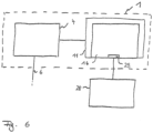
- Fig. 6 schematically shows the treatment apparatus 1, by reference to which the importance of the planning device 16 shall be explained in more detail.
- the treatment apparatus 1 comprises at least two devices or modules.
- the laser device 4 already described emits the laser beam 6 onto the eye 2.
- operation of the laser device 4 is effected fully automatically by the control device 11, i.e. the laser device 4 starts generating and deflecting the laser beam 6 in response to a corresponding start signal and, thus, generates cut surfaces, which are structured as described, in order to remove the corneal volume 21 or to generate the transplant 26 from the transplantation material.
- the laser device 4 receives the control signals required for operation from the control device 11, to which corresponding control data have been provided before. This is effected by the planning device 16, which is shown in Fig.
- the planning device 16 may also be provided separately and may communicate with the control device 11 either in a wire-bound or wireless manner. It is then only essential to provide a corresponding data transmission channel between the planning device 16 and the control device 11.
- the planning device 16 generates a control data set which is provided to the control device 11 to carry out the transplantation.
- the planning device uses measurement data relating to the cornea of the eye as well as transplantation material data relating to the transplantation material from which the transplant 26 is to be cut out.
- these data come from a measurement device 28, which has previously measured the eye 2 of the patient 2.
- a similar measurement device 28 may, of course, be provided for the transplantation material as well.
- the measurement device 28 may have any design whatsoever and may transmit the corresponding data to the interface 29 of the planning device 16.
- the data relating to the transplantation material may also come from other sources and need not be generated before directly by a measurement.
- the planning device assists the user of the treatment apparatus 1 in defining the cut surface for isolation of the corneal volume 21.
- This may even include a fully automatic definition of the cut surfaces, which may be effected, for example, by the planning device 16 recognizing the corneal volume 21 to be removed from the measurement data, defining the boundary surfaces of said corneal volume 21 as cut surfaces, and generating therefrom suitable control data for the control device 11.
- the planning device 16 may provide input means by which a user inputs the cut surfaces in the form of geometrical parameters, etc.
- Intermediate degrees provide suggestions for the cut surfaces, which the planning device 16 generates automatically and which can then be modified by an operator. Basically, all the concepts already explained in the above, more generic part of the specification can be applied here in the planning device 16.
- the planning device 16 uses a computing unit (e.g. a computer) provided therein, on the one hand, to generate the control data for producing the chamber 25, and, on the other hand, also to compute the cut surfaces for cutting the transplant 26. In doing so, it preferably takes the transplantation material data into consideration.
- the control data for the transplantation cut are generated automatically.
- a desired correction of an eyesight defect can be defined, which the computing unit then converts into a geometrical deviation between the chamber 25 and the transplant 26 in order to modify the corneal refraction accordingly.
- Fig. 7 shows a block diagram explaining the function of the planning device 16.
- the planning device 16 serves to define cut surfaces for cornea transplantation. For this purpose, it is supplied with data relating to the eye as well as data relating to the transplantation material and generates, preferably depending on previously input parameters, the control data for producing the cut surface on the eye, and automatically generates matching control data for cutting the transplant. In doing so, it is essential for the planning device that, first, the cut surface is defined for isolation of the corneal volume and then, based on such corneal cut surface, the corresponding transplant cut surfaces are determined. Such determination is preferably effected fully automatically.
- parameters can be taken into consideration which result from the geometry and structure of the transplantation material. Additional parameters, which may be included in automatically determining the transplant cut surfaces, comprise the already mentioned correction of eyesight defects.
- the transplant cut surface is formed to deviate from the corneal cut surface such that the transplant, once inserted, has a certain refractive effect together with the remaining refractive elements of the recipient's eye to modify the initial pre-transplantation refraction.
- the planning device 16 uses the determination of the geometry of the recipient's eye, in particular of the cornea of the recipient's eye, and preferably, as already explained, also the geometry of the transplantation material, e.g. of donor cornea.
- the measurement devices or diagnostic devices already mentioned in the generic part of the specification are suitable for this purpose and can communicate with the planning device 16 via a corresponding data communication channel, as already described above.
- the detectable geometries of the recipient's eye or of the transplantation material comprise, for example, the shape of the anterior corneal surface and of the posterior corneal surface as well as structures within the recipient's cornea, and, where applicable, also the position of the eye lens and of further boundary surface parameters.
- individual or several of these geometries or geometrical parameters, respectively are graphically displayed for the user on a screen, in which case a superimposed graphic display is also possible.
- Planning of the cut geometries can be assisted by the planning device 16 in a manner similar to a CAD system in the form of a special linguistic syntax or by means of a graphic input.
- the planning device 16 may comprise further special control mechanisms which examine and evaluate the overlap or the contact of cut surfaces in determining the corneal cut surface and, where applicable, effect a corresponding display or reject a cut input by the user.
- the planning device In order to make it easier to define a certain shape, it is preferred for the planning device to utilize symmetries when producing cut surfaces.
- face and peripheral cuts may preferably be designed to have cylindrical symmetry.
- angle-dependent aspect ratios for generating elliptical shapes are possible.
- the planning device may allow for the peripheral surfaces of the corneal volume to be defined such that sutures for fixing the transplants become unnecessary.
- the planning device as well as the treatment apparatus may be combined with each other and with further devices as desired.
- a data network of diagnostic devices and treatment devices may be used.
- an independent planning device 16 has advantages in terms of sterility, because the planning device 16 can then be arranged outside the sterile operating area, which facilitates intensive planning work. Of course, if priority is given to very rapid planning, the planning device may also be arranged within the sterile operating area.
- the cut surfaces for both the cornea and the transplant are usually two-dimensionally curved cuts. Therefore, the planning device provides corresponding input possibilities and, in particular a graphic input of the corneal cut surfaces, a graphic representation of the cut resulting there from, as well as means for computing and optimizing a refractive effect.
- treatment apparatus 1 or the planning device 16 also specifically executes the method generally explained above.
- a further embodiment of the planning device is in the form of a computer program or of a corresponding data carrier comprising a computer program, which implements the planning device on one or more interconnected computers, so that the input of the measurement data or the transplantation material data into the computer is effected by a suitable data transmission means, and the control data are transmitted from this computer to the control device 11, for which purpose data transmission means, again known to the person skilled in the art, are suitable.
Description
- The invention relates to a planning device for generating control data for a treatment apparatus for cornea transplantation, said apparatus using a laser device to separate, by at least one cut surface in the cornea, a corneal volume from the surrounding cornea, which corneal volume is to be removed, and to separate, by at least one cut surface in a transplantation material, a transplant from the surrounding transplantation material, which transplant is to be inserted into the cornea.
- The invention further relates to a treatment apparatus for cornea transplantation, which comprises a planning device of the aforementioned type.
- Further, the invention relates to a method of generating control data for a treatment apparatus for cornea transplantation, which apparatus uses a laser device to separate a corneal volume, which is to be removed, from the surrounding cornea by at least one cut surface in the cornea and to separate a transplant, which is to be inserted into the cornea, from a surrounding transplantation material by at least one cut surface in the transplantation material.
- It has been known for a long time in ophthalmic surgery to correct changes in the cornea by means of transplantations. The term "transplantation" is understood in this context and also in the following description in the broadest sense, i.e. it comprises an allogenic transplantation, in which the cornea donor and the recipient belong to the same species, i.e. human cornea is transplanted. However, the term also comprises xenogenic transplantation, wherein animal cornea is implanted in the human eye. Further, the term also comprises alloplastic transplantation, wherein artificial material is implanted. The latter is often referred to also as implantation. Further, said term comprises a transplantation, wherein biotechnologically produced cornea (e.g. from stem cells) is used.
- It has been known for a long time in the state of the art to carry out transplantations of cornea by cutting a corneal volume to be removed out of the cornea and replacing it with a transplant having, if possible, the same size. In this connection,
US 2006/0020259 A1 discloses that the conventional cutting by a knife can be replaced by the use of a treatment apparatus comprising a laser, so that cutting is effected in a contact-free manner by laser radiation. -
EP 1719483 A1 relates to laser-based cutting of cornea and donor material in transplantation surgery. An ablating laser is used to ablate a volume from the cornea which should be replaced by donor material. The laser radiation acts by ablating material, i.e. the laser radiation is absorbed at the front surface of the material to which the laser radiation is directed. -
DE 102004057343 A1 discloses special suture techniques in transplantation surgery. By suturing material at special locations, the introduction of visual errors can be avoided. As an option it is disclosed to obtain a targeted deformation of the cornea by applying a particular suture technology. - In addition to healing corneal diseases, transplantations are also known in the state of the art for correction of eyesight defects. In this connection, reference is made especially to
WO 03/005920 A1 - The already mentioned
US 2006/0020259 A1 , which intends to replace damaged or deceased cornea by way of transplantation, discloses that a cavity is generated in the cornea by means of laser radiation according to a predetermined cutting pattern. Next, a piece of cornea having, if possible, identical dimensions is cut out of the donor material by laser radiation and is then inserted into the previously generated cavity. The US document describes it as essential for the generated cavity and the cut-out piece to be identical, if possible, and a certain oversize of the transplant is regarded as advantageous for the transplant to be placed in the cavity as securely as possibly. In this case, the US document starts out from a predetermined cutting pattern for the cavity and allows the surgeon to perform minor modifications while cutting the transplant. Based on a pre-set shape of the cavity, the surgeon can, thus, design the transplant such that its dimensions vary slightly, in order to achieve optimum in-growth of the transplant into the cornea of the recipient. -
WO 03/005920 A1 - In both cases, the cut surfaces in the eye are produced by known laser technology using an optical effect of laser radiation in the cornea, for example, by producing an optical breakthrough. In this case, pulsed laser radiation is usually applied. It is also known to introduce individual pulses, whose energy is below a threshold value for an optical breakthrough, into the tissue or material in a superimposed manner such that a separation of material or tissue is achieved thereby as well.
- This concept of producing cuts in the corneal tissue allows a large variety of cuts. The treating surgeon, therefore, theoretically has very great freedom in selecting the cut. However, this does not apply to the approach of
WO 03/005920 US 2006/0020259 A1 does not relate to the shape of the cut at all, but merely refers to a "predetermined cutting pattern". Also, in this reference, the geometry of the cornea of both the recipient and the donor is the same; therefore, the control parameters of the laser device are also identical. - Thus, both references do not provide a person skilled in the art with any clue as to the cutting pattern to be selected. This is the starting point of the invention. It is an object of the invention to provide assistance allowing exhaustive use of the large variety of possible cut geometries, without undesired influences resulting from predetermined shapes of an implant or predetermined cut surfaces in the recipient's cornea. Also, there is to be greater freedom in selecting the transplantation material.
- According to the invention, as defined in the independent claims, this object is achieved by a planning device for generating control data for a treatment apparatus for cornea transplantation, which apparatus uses a laser device to separate, by at least one cut surface in the cornea, a corneal volume from the surrounding cornea, which corneal volume is to be removed, and to separate, by at least one cut surface in a transplantation material, a transplant from the surrounding transplantation material, which transplant is to be inserted into the cornea, wherein the planning device comprises an interface for supplying measurement data relating to parameters of the cornea, computing means for defining the corneal cut surface on the basis of the measurement data, which cut surface confines the corneal volume to be removed, wherein said computing means further determine the transplant cut surface, which transplant cut surface depends on the defined corneal cut surface and confines the transplant, and said computing means generate control data sets for the corneal cut surface and the transplant cut surface to control the laser device, wherein the respective cut surfaces can be produced by the laser device when using the control data sets, so as to isolate the corneal volume and the transplant and to make them removable, as well as to make the transplant transplantable.
- The object is further achieved by a treatment apparatus for transplantation of cornea of a patient's eye, said apparatus comprising an interface for supplying measurement data relating to parameters of the cornea and for supplying transplantation material data relating to parameters of the transplantation material, the laser device which separates, by at least one cut surface in the cornea, a corneal volume from the surrounding cornea by means of laser radiation according to control data, which corneal volume is to be removed, and separates, by at least one cut surface in the transplantation material, a transplant from a surrounding transplantation material, which transplant is to be inserted into the cornea, and a planning device of the above-described type for generating the control data of the above-described type.
- The object is further achieved by a method generating control data for a treatment apparatus for cornea transplantation, said method using a laser device to separate, by at least one cut surface in the cornea, a corneal volume from the surrounding cornea, which corneal volume is to be removed, and to separate, by at least one cut surface in the transplantation material, a transplant from a surrounding transplantation material, which transplant is to be inserted into the cornea, said method comprising the following steps: providing measurement data relating to parameters of the cornea, defining a corneal cut surface using said measurement data, which cut surface confines the corneal volume to be removed, automatically determining a transplant cut surface, said transplant cut surface depending on the defined corneal cut surface and confining the transplant, and generating control data sets for the corneal cut surface and the transplant cut surface in order to control the laser device, so that the respective cut surfaces can be produced by the laser device using the control data sets, in order to isolate the corneal volume and the transplant and to make them removable, as well as to make the transplant transplantable.
- Thus, the invention provides for a planning device and a treatment apparatus, as well as corresponding planning methods, which assist the generation of control data or the transplantation of cornea such that the corneal cut surface to be formed in the recipient's cornea can be freely selected without having to consider the production of the transplant cut surface by which the transplant is produced from the donor material. The transplant material may comprise both human or animal donor cornea as well as an artificial, in particular a biotechnologically produced material.
- According to the invention, the planning device as well as the treatment apparatus equipped therewith and the method for generating the control data automatically generates the control data set matching the freely defined corneal cut surface and causes the appropriate control of the treatment apparatus in order to cut the transplant accordingly. The corneal cut surface can, thus, be selected from a predetermined set as well as be freely defined or composed of predetermined patterns or by modifications of predetermined patterns.
- When defining the transplant cut surface, transplantation material data are preferably taken into consideration, because this provides greater freedom in the selection of the transplantation material. For this purpose, the planning device conveniently comprises an interface for supplying transplantation material data relating to parameters of the transplantation material. The measurement data concerning parameters of the recipient's cornea as well as, where applicable, also the transplantation material data concerning parameters of the transplantation material are conveniently obtained by measuring the recipient's eye or the recipient's cornea or the transplantation material, respectively. In particular, it is possible to determine the geometry of the eye, in particular of the recipient's cornea and, where applicable, of the donor, using a diagnostic device. For this purpose, OCT and ultrasonic systems are suitable, for example, the IOL Master or AC Master or Visante devices of Carl Zeiss Meditec AG, or other systems using optical coherence tomography. The geometries thus determined for the recipient and the donor can relate, for example, to the anterior surface of the cornea and the posterior surface of the cornea, and, where applicable, also to structures within the cornea. If necessary, the position of the eye lens and the parameters of further boundary surfaces or optically active surfaces can be measured and taken into consideration.
- The planning device is preferably provided in the form of a planning station, which graphically displays to a user on a screen the acquired measurement data or transplantation material data, either individually or jointly, or even in a superimposed manner. Since the planning task is a spatially complex task in some cases, a 3D screen is provided for easier working.
- The computing means conveniently allow a user to input cut geometries, which are subsequently realized. The planning of the cut geometries can then be effected, in a manner similar to a CAD system, in the form of a special linguistic syntax or by a graphic input. It is basically possible that the user may also select, dimension and combine desired shapes from a sort of kit. In preferred embodiments, software-based control mechanisms are further available in order to check the geometric consistency of the pre-selected cuts, for example, in order to determine and evaluate regions of overlap or contact between cuts.
- The computing means allow the user to design the cut individually with utmost liberty in terms of shape. For this purpose, the computing means may comprise a computer.
- For further assistance, the computing means or the respective method provide to evaluate the application of symmetries in order to simplify the definition of the corneal cut surface. For example, face and peripheral cuts can be defined in a cylinder-symmetrical manner. Additionally and alternatively, angle-dependent aspect ratios for forming ellipses are possible. Preferably, the defining means allow the user to program or define peripheral or rim shapes which he knows or assumes to be favorable for the in-growth of the transplant. This includes the possibility for the user to define peripheral cuts allowing him to dispense with sutures for fixing the transplant.
- The primary goal of cornea transplantation is usually to replace the diseased or injured corneal tissue, thereby restoring the patient's eyesight. Therefore, in a preferred further embodiment, a refractive correction or the change in refraction by the transplantation is additionally taken into consideration in order to avoid, if possible, any potentially required subsequent refractive corrections. Thus, a further embodiment provides for the computing means to cause a geometrical deviation between the corneal volume and the transplant according to a predetermined change in refraction, when determining the transplant cut surface, in order to achieve not only a replacement of tissue by said transplantation, but also a selective refractive effect. This allows to provide a transplant such that, after insertion, it has a specific refractive effect together with the remaining refractively effective organs of the recipient's eye, said effect, for example, correcting a previously present eyesight defect. According to this further embodiment, the invention preferably comprises a software tool for evaluating the refractive effect of transplantation as well as means for optimizing at least one refractive cut with respect to the predetermined change in refraction.
- The replacement of corneal tissue by way of transplantation quite fundamentally also has an effect on the optical imaging quality, of course, because boundary surfaces which did not exist before are produced in the cornea. The position of the boundary surfaces and, thus, the position of the corneal cut surface is of great importance. Now, in order to allow placing of the cut surface such that the effects on the eye's optical imaging quality after transplantation are minimal, the invention provides a further embodiment of the planning device or of the treatment apparatus, respectively, wherein the computing means compute the transplanted eye's optical imaging quality which is obtained upon carrying out the transplantation, such computing being effected as a function of the corneal cut surface, and display the imaging quality on a display device. For example, a test image or wavefront prognosis data are possible here, whose reproduction is modified according to the imaging quality. Thus, when defining the cut surface, one will automatically see how the selection of the cut surface geometry affects the optical imaging quality.
- In order to achieve a maximum degree of automation, it is also possible to input or predetermine in the computing means only the corneal volume which is to be removed during corneal transplantation, and the computing means can then automatically define a setting for the corneal cut surface using predetermined cut geometries or numerical optimization algorithms respectively. This setting is then still optionally modifiable.
- Such modification is particularly easy for a user, if a display device for visual representation of the cornea and of the transplantation material is provided with simultaneous representation of the corneal cut surface and of the transplant cut surface.
- The measurement data or the transplantation material data, respectively, can be optionally generated by one or more of the following devices: autorefractor, refractometer, keratometer, aberrometer, wavefront measurement device, OCT.
- In a further embodiment of the invention, intra-operative monitoring of the cut is provided in the treatment apparatus, so that the progress of the cut is being monitored continuously. In addition, the measurement of the result of surgery can be provided by means of an integrated diagnostic device or a linked diagnostic device, which may be one of the aforementioned measurement devices, for example. The surgical result can be defined in terms of the exact fit of the inserted transplant, the sizes of cavities or the absence of cavities, respectively, warping of the cornea or of the inserted transplant, the number and size of epithelial cells carried into the stroma, or the absence of such epithelial cells, respectively, soiling of the cornea, for example, by fibers etc.
- It will be appreciated that the aforementioned features and those yet to be explained below can be employed not only in the indicated combinations, but also in other combinations or alone, without departing from the scope of the present invention. The scope of the invention is defined by the following claims.
- The invention will be explained in more detail below, by way of example and with reference to the drawing, wherein:
- Fig. 1
- shows a schematic representation of a treatment apparatus comprising a planning device for carrying out a cornea transplantation;
- Fig. 2
- shows a schematic representation of the effect of laser radiation used in the treatment apparatus of
Fig. 1 ; - Fig. 3
- shows a further schematic representation of the treatment apparatus of
Fig. 1 with respect to the introduction of laser radiation; - Fig. 4
- shows a schematic sectional view of the cornea, illustrating the removal of the corneal volume in connection with the cornea transplantation;
- Fig. 5a
- shows a perspective view of a cavity produced in the recipient's cornea;
- Fig. 5b
- shows a perspective view of the transplant prior to insertion into the recipient's cornea;
- Fig. 6
- shows a schematic view of the construction of the treatment apparatus of
Fig. 1 with particular reference to the planning device present wherein, and - Fig. 7
- shows a block diagram concerning the function of the planning device.
- A treatment apparatus for cornea transplantation is shown in
Fig. 1 and bears the general reference numeral 1. Using the treatment apparatus 1, a cornea transplantation is carried out on aneye 2 of apatient 3. For this purpose, the treatment apparatus 1 comprises a laser device 4, which emits alaser beam 6 from alaser source 5, saidlaser beam 6 being directed into theeye 2 or the cornea, respectively, as afocused beam 7. Thelaser beam 6 is preferably a pulsed laser beam having a wavelength of between 400 nanometers and 10 micrometers. Further, the pulse duration of thelaser beam 6 is in the range between 1 femtosecond and 10 picoseconds, allowing pulse repetition frequencies of 1 to 1000 kilohertz and pulse energies of between 0.01 microjoules and 10 microjoules. Thereby, the treatment apparatus 1 produces a cut surface in the cornea of theeye 2 by deflecting the pulsed laser radiation. Further, a scanner 8 as well as a radiation-intensity modulator 9 is provided in the laser device 4 or itslaser source 5, respectively. - The
patient 3 is lying on a table 10, which is shiftable in three spatial directions in order to align theeye 2 with the incidence of thelaser beam 6. In a preferred construction, the table 10 is shiftable by a motor drive. - Control may be effected, in particular, by a
control device 11 which generally controls the operation of the treatment apparatus 1 and is connected to the treatment apparatus via suitable data links, forexample connecting lines 12, for this purpose. This communication may, of course, be effected also via other paths, for example by light guides or by radio. Thecontrol device 11 performs the corresponding settings, time control of the treatment apparatus 1, in particular of the laser device 4, and thus performs corresponding functions of the treatment apparatus 1. - As shown in
Fig. 1 , not only the table 10, on which thepatient 3 is lying, is provided in connection with the treatment apparatus 1, but also afixture 13, which holds donor cornea (not shown inFig. 1 ), for example, by the use of amount 14. Thefixture 13 is provided such that it matches the shape of the present donor cornea. For example, in the case of a donor's eye, themount 14 shown as an example inFig. 1 can be used. In the case of already removed cornea or in the case of synthetically produced cornea or cornea from animal tissue, respectively, the fixture can also be designed differently, for example, without themount 14. Themount 14 generally has a design matching the transplantation material from which the transplant is cut out. - The treatment apparatus 1 further comprises a fixing
device 15, which positionally fixes the cornea of theeye 2 with respect to the laser device 4. This fixingdevice 15 may comprise a knowncontact glass 45, which is placed in contact with the cornea by a vacuum and which imparts a desired geometrical shape to the cornea. Such contact glasses are known to the person skilled in the art from the state of the art, for example fromDE 102005040338 A1 . - The
control device 11 of the treatment apparatus 1 further comprises aplanning device 16, which will be explained in more detail below. -
Fig. 2 schematically shows the effect of theincident laser beam 6. Thelaser beam 6 is focused and is incident as thefocused laser beam 7 in thecornea 17 of theeye 2. Schematically shownoptics 18 are provided for focusing. They effect a focus in thecornea 17, in which focus the laser radiation energy density is so high that, in combination with the pulse duration of thepulsed laser radiation 6, a non-linear effect appears in thecornea 17. For example, each pulse of thepulsed laser radiation 6 in thefocus 19 may produce an optical breakthrough in thecornea 17, which in turn initiates a plasma bubble indicated only schematically inFig. 2 . When the plasma bubble forms, the tissue layer separation comprises an area larger than thefocus 19, although the conditions for producing the optical breakthrough are achieved only in thefocus 19. In order for an optical breakthrough to be produced by each laser pulse, the energy density, i.e. the fluence of the laser radiation, must be above a certain pulse duration-dependent threshold value. This connection is known to the person skilled in the art, for example, fromDE 69500997 T2 . Alternatively, a tissue-separating effect can also be achieved by pulsed laser radiation in that several laser radiation pulses are emitted into a region where the focus spots overlap. In this case, several laser radiation pulses cooperate to achieve a tissue-separating effect. - However, the type of tissue separation used by the treatment apparatus is not really relevant to the following description; it is only essential that a cut surface is generated in the
cornea 17 of theeye 2. - Now, in order to perform a transplantation of cornea, a corneal volume is removed from a region within the
cornea 17 by means of thelaser radiation 6, separating tissue layers therein which isolate the corneal volume and enable removal of the latter then. For isolation of the corneal volume to be removed, the position of thefocus 17 of thefocused laser radiation 7 in thecornea 17 is shifted for example, in cases where pulsed laser radiation is introduced. This is schematically shown inFig. 3 . -
Fig. 3 shows the elements of the treatment apparatus 1 only insofar as they are required in order to understand how the cut surfaces are produced. As already mentioned, thelaser beam 6 is bundled into afocus 19 in thecornea 17, and the position of thefocus 19 in the cornea is shifted such that focused energy from laser radiation pulses is introduced into the tissue of thecornea 17 at different locations so as to produce cut surfaces. Thelaser radiation 6 is preferably provided by thelaser source 5 as pulsed radiation. The scanner 8 has a two-part design in the construction ofFig. 3 and consists of an xy-scanner 8a, which is realized, in one variant, by two galvanometer mirrors with substantially orthogonal deflection. The scanner 8a two-dimensionally deflects thelaser beam 6 coming from thelaser source 5, so that a deflectedlaser beam 20 is present behind the scanner 8. Thus, the scanner 8a causes shifting of the position of thefocus 19 substantially perpendicular to the main direction of incidence of thelaser beam 6 in thecornea 17. For shifting of the depth position, a z-scanner 8b is provided in the scanner 8 in addition to the xy-scanner 8a, for example, in the form of an adjustable telescope. The z-scanner 8b provides for changes of the z-position of thefocus 19, i.e. of its position along the optical axis of incidence. The z-scanner 8b may be arranged preceding or following the xy-scanner 8a. - It is not essential for the functional principle of the treatment apparatus 1 how the individual coordinates are assigned to the spatial directions nor that deflection by the scanner 8a is effected along mutually orthogonal axes. On the contrary, any scanner may be used which can shift the
focus 19 in a plane in which the axis of incidence of the optical radiation is not located. - Of course, it is also possible to use any non-Cartesian coordinate systems whatsoever for deflection or control of the position of the
focus 19. Examples include spherical coordinates or cylindrical coordinates. - The position of the
focus 19 is controlled by thescanners 8a, 8b under control of thecontrol device 11, which performs suitable settings of thelaser source 5, of the modulator 9 (not shown inFig. 3 ) as well as the scanner 8. Thecontrol device 11 ensures suitable operation of thelaser source 5 as well as the three-dimensional focus shift described here as an example, thus finally producing a cut surface which isolates a defined corneal volume that is to be removed for transplantation. - The
control device 11 works according to predetermined control data, which are specified, for example, to the laser device 4 described here merely as an example, as target points for focus shifting. The control data are usually compiled in a control data set, which provides geometrical parameters for the cut surface to be formed, e.g. the coordinates of the target points as a pattern. In this embodiment, the control data set then also includes concrete set values for the focus position shifting mechanism, e.g. for the scanner 8. -
Fig. 4 shows an example of how to produce the cut surface using the treatment apparatus 1. Acorneal volume 21 is isolated in thecornea 17 by shifting thefocus 19, into which thefocused beam 7 is bundled. For this purpose, cut surfaces are formed, which are provided here, by way of example, as an interior flap cutsurface 22 as well as a posterior lenticle cutsurface 23. These terms are to be understood here merely as examples and are intended to refer to the conventional LASIK or FLEX methods, for which the treatment apparatus 1 is known, as already described. It is only essential here that the cut surfaces 22 and 23 as well as peripheral cuts, which are not referred to in detail, isolate thecorneal volume 21. Further, a corneal lamella anteriorly limiting thecorneal volume 21 can be folded aside due to aperipheral cut 24 so as to allow removal of thecorneal volume 21. The type of isolation of thecorneal volume 21 and its removal is not vital for the present invention and other embodiments are also possible. -
Fig. 5a schematically shows the state after removal of the corneal volume. Thus, achamber 25 has been formed in thecornea 17, said chamber serving as a cavity which receives the transplant. The transplant is cut out from a transplantation material, also using the treatment apparatus 1, preferably using precisely the same effects and mechanisms which were employed in order to produce thechamber 25. Thetransplant 26 thus produced is then inserted, asFig. 5b shows, into thechamber 25, which process is illustrated by arrows 27 inFig. 5b . -
Fig. 6 schematically shows the treatment apparatus 1, by reference to which the importance of theplanning device 16 shall be explained in more detail. In this variant, the treatment apparatus 1 comprises at least two devices or modules. The laser device 4 already described emits thelaser beam 6 onto theeye 2. As already described, operation of the laser device 4 is effected fully automatically by thecontrol device 11, i.e. the laser device 4 starts generating and deflecting thelaser beam 6 in response to a corresponding start signal and, thus, generates cut surfaces, which are structured as described, in order to remove thecorneal volume 21 or to generate thetransplant 26 from the transplantation material. The laser device 4 receives the control signals required for operation from thecontrol device 11, to which corresponding control data have been provided before. This is effected by theplanning device 16, which is shown inFig. 6 merely by way of example, as part of thecontrol device 11. Of course, theplanning device 16 may also be provided separately and may communicate with thecontrol device 11 either in a wire-bound or wireless manner. It is then only essential to provide a corresponding data transmission channel between the planningdevice 16 and thecontrol device 11. - The
planning device 16 generates a control data set which is provided to thecontrol device 11 to carry out the transplantation. In doing so, the planning device uses measurement data relating to the cornea of the eye as well as transplantation material data relating to the transplantation material from which thetransplant 26 is to be cut out. In the present embodiment, these data come from ameasurement device 28, which has previously measured theeye 2 of thepatient 2. Asimilar measurement device 28 may, of course, be provided for the transplantation material as well. Of course, themeasurement device 28 may have any design whatsoever and may transmit the corresponding data to theinterface 29 of theplanning device 16. - The data relating to the transplantation material may also come from other sources and need not be generated before directly by a measurement.
- Now, the planning device assists the user of the treatment apparatus 1 in defining the cut surface for isolation of the
corneal volume 21. This may even include a fully automatic definition of the cut surfaces, which may be effected, for example, by theplanning device 16 recognizing thecorneal volume 21 to be removed from the measurement data, defining the boundary surfaces of saidcorneal volume 21 as cut surfaces, and generating therefrom suitable control data for thecontrol device 11. At the other end of the degree of automation, theplanning device 16 may provide input means by which a user inputs the cut surfaces in the form of geometrical parameters, etc. Intermediate degrees provide suggestions for the cut surfaces, which theplanning device 16 generates automatically and which can then be modified by an operator. Basically, all the concepts already explained in the above, more generic part of the specification can be applied here in theplanning device 16. - After defining the cut surfaces for the
corneal volume 21, theplanning device 16 uses a computing unit (e.g. a computer) provided therein, on the one hand, to generate the control data for producing thechamber 25, and, on the other hand, also to compute the cut surfaces for cutting thetransplant 26. In doing so, it preferably takes the transplantation material data into consideration. The control data for the transplantation cut are generated automatically. - Further, a desired correction of an eyesight defect can be defined, which the computing unit then converts into a geometrical deviation between the
chamber 25 and thetransplant 26 in order to modify the corneal refraction accordingly. - Fig. 7 shows a block diagram explaining the function of the
planning device 16. Theplanning device 16 serves to define cut surfaces for cornea transplantation. For this purpose, it is supplied with data relating to the eye as well as data relating to the transplantation material and generates, preferably depending on previously input parameters, the control data for producing the cut surface on the eye, and automatically generates matching control data for cutting the transplant. In doing so, it is essential for the planning device that, first, the cut surface is defined for isolation of the corneal volume and then, based on such corneal cut surface, the corresponding transplant cut surfaces are determined. Such determination is preferably effected fully automatically. - In this case, parameters can be taken into consideration which result from the geometry and structure of the transplantation material. Additional parameters, which may be included in automatically determining the transplant cut surfaces, comprise the already mentioned correction of eyesight defects. In this case, the transplant cut surface is formed to deviate from the corneal cut surface such that the transplant, once inserted, has a certain refractive effect together with the remaining refractive elements of the recipient's eye to modify the initial pre-transplantation refraction.
- In a specific embodiment, the
planning device 16 uses the determination of the geometry of the recipient's eye, in particular of the cornea of the recipient's eye, and preferably, as already explained, also the geometry of the transplantation material, e.g. of donor cornea. The measurement devices or diagnostic devices already mentioned in the generic part of the specification are suitable for this purpose and can communicate with theplanning device 16 via a corresponding data communication channel, as already described above. - The detectable geometries of the recipient's eye or of the transplantation material comprise, for example, the shape of the anterior corneal surface and of the posterior corneal surface as well as structures within the recipient's cornea, and, where applicable, also the position of the eye lens and of further boundary surface parameters. In a preferred embodiment, individual or several of these geometries or geometrical parameters, respectively, are graphically displayed for the user on a screen, in which case a superimposed graphic display is also possible. Planning of the cut geometries can be assisted by the
planning device 16 in a manner similar to a CAD system in the form of a special linguistic syntax or by means of a graphic input. - Conveniently, it is also possible to provide the planning device with a memory, which stores possible geometries for the corneal cut surface, for example in the manner of a kit. The user can then select, dimension and combine the desired shapes. Moreover, the
planning device 16 may comprise further special control mechanisms which examine and evaluate the overlap or the contact of cut surfaces in determining the corneal cut surface and, where applicable, effect a corresponding display or reject a cut input by the user. - In this manner, an individual design of the cut can be facilitated for the user, with almost complete freedom in terms of shapes. In order to make it easier to define a certain shape, it is preferred for the planning device to utilize symmetries when producing cut surfaces. For example, face and peripheral cuts may preferably be designed to have cylindrical symmetry. In addition, angle-dependent aspect ratios for generating elliptical shapes are possible. Moreover, the planning device may allow for the peripheral surfaces of the corneal volume to be defined such that sutures for fixing the transplants become unnecessary.
- Of course, the planning device as well as the treatment apparatus may be combined with each other and with further devices as desired. In particular, a data network of diagnostic devices and treatment devices may be used.
- However, an
independent planning device 16 has advantages in terms of sterility, because theplanning device 16 can then be arranged outside the sterile operating area, which facilitates intensive planning work. Of course, if priority is given to very rapid planning, the planning device may also be arranged within the sterile operating area. - The cut surfaces for both the cornea and the transplant are usually two-dimensionally curved cuts. Therefore, the planning device provides corresponding input possibilities and, in particular a graphic input of the corneal cut surfaces, a graphic representation of the cut resulting there from, as well as means for computing and optimizing a refractive effect.
- It should also be noted that the treatment apparatus 1 or the
planning device 16, of course, also specifically executes the method generally explained above. - A further embodiment of the planning device is in the form of a computer program or of a corresponding data carrier comprising a computer program, which implements the planning device on one or more interconnected computers, so that the input of the measurement data or the transplantation material data into the computer is effected by a suitable data transmission means, and the control data are transmitted from this computer to the
control device 11, for which purpose data transmission means, again known to the person skilled in the art, are suitable.
Claims (13)
- A planning device for generating control data for a treatment apparatus (1) for cornea transplantation, said apparatus is configured for using a laser device (4) to separate, by at least one cut surface (20, 23) in the cornea (17), a corneal volume (21), which corneal volume (21) is to be removed from surrounding cornea (5), and to separate, by at least one cut surface in a transplantation material, a transplant (26) from the surrounding transplantation material, which transplant (26) is to be inserted into the cornea, wherein the planning device (16) comprises:- an interface (29) for supplying measurement data relating to parameters of the cornea (17), and- computing means configured for defining a corneal cut surface (22, 23) on the basis of the measurement data, which corneal cut surface (22, 23) confines the corneal volume (21) to be removed, wherein this corneal volume (21) is located within the cornea (17) and below a front face of the cornea (17),- wherein said computing means are further configured- to determine a transplant cut surface, which transplant cut surface depends on the defined corneal cut surface (22, 23) and confines the transplant (26), and- to generate control data sets for the corneal cut surface (22, 23) and the transplant cut surface to control the laser device (4), wherein the respective cut surfaces can be produced by the laser device (4) when using the control data sets, so as to isolate the corneal volume (21) and the transplant (26) from the surrounding cornea and transplantation material respectively and to make them removable, as well as to make the transplant (26) transplantable,- wherein the computing means, when determining the transplant cut surface, are further configured to cause a geometrical deviation between the corneal volume (21) and the transplant (26), which deviation depends on a predetermined change in refraction, so as to achieve not only a replacement of tissue by said transplantation but also a selective refractive effect in order to correct eyesight defects.
- The device as claimed in claim 1, wherein the computing means comprise a storage medium in which different user-selectable cut surface geometries are stored, wherein in particular the stored cut geometries are modifiable and means for re-storing modified cut geometries are provided.
- The device as claimed in claim 1 or 2, wherein the transplant material is artificial material.
- The device as claimed in any one of the above claims, wherein the computing means compute an optical imaging quality of the transplanted eye (2), which imaging quality results after carrying out the transplantation, as a function of the corneal cut surface (22, 23) and represent the imaging quality on a display device.
- The device as claimed in any one of the above claims, comprising a display device for visual representation of the cornea (17) and of the transplantation material with simultaneous representation of the corneal cut surface (22, 23) and of the transplant cut surface.
- The device as claimed in any one of the above claims, wherein a measurement device (28) is connected to the interface (29), said measurement device (28) generating measurement data from a measurement of the eye (2) and supplying said data to the planning device (16), and said measurement device (28) comprising one or more of the following devices: autorefractor, refractometer, keratometer, aberrometer, wavefront measurement device, OCT.
- A treatment apparatus for cornea transplantation, said apparatus comprising- an interface (29) supplying measurement data relating to parameters of the cornea (17),- a laser device (4), which uses laser radiation to separate, by at least one cut surface (22, 23) in the cornea (17), a corneal volume (21) from the surrounding cornea (17), which corneal volume (21) is to be removed, and to separate, by at least one cut surface in the transplantation material, a transplant (26) from a surrounding transplantation material, which transplant (26) is to be inserted into the cornea, and- a planning device (16) for generating the control data according to any one of the above claims.
- A method for generating control data for a laser treatment apparatus (1) for cornea transplantation, said apparatus using a laser device (4) to separate, by at least one cut surface (22, 23) in the cornea (17), a corneal volume (21) from the surrounding cornea (17), which corneal volume (21) is to be removed, and to separate, by at least one cut surface in the transplantation material, a transplant (26) from a surrounding transplantation material, which transplant (26) is to be inserted into the cornea (17), said method comprising the following steps:- providing measurement data relating to parameters of the cornea (17),- using the measurement data to define a corneal cut surface (22, 23) which confines the corneal volume (21) within the cornea (17) and below a front face of the cornea (17),- automatically determining a transplant cut surface, said transplant cut surface depending on the defined corneal cut surface (22, 23) and confining the transplant (26), and generating control data sets for the corneal cut surface (22, 23) and the transplant cut surface to control the laser device (4) such that the respective cut surfaces will be generated by the laser device when using the control data sets, so as to isolate the corneal volume (21) and the transplant (26) and to make them removable, as well as to make the transplant (26) transplantable,- wherein, when determining the transplant cut surface, a geometrical deviation between the corneal volume (21) and the transplant (26) is caused, which deviation depends on a predetermined change in refraction, so as to achieve not only a replacement of tissue by said transplantation but also a selective refractive effect in order to correct eyesight defects, wherein in particular the transplant material is artificial material.
- The method as claimed in claim 8, wherein a user is offered a selection of pre-stored cut surface geometries when defining the corneal cut surface, wherein optionally the pre-stored cut surface geometries are modified and stored again.
- The method as claimed in any one of the above method claims, wherein the optical imaging quality the transplanted eye (2) will have after carrying out the transplantation is computed as a function of the corneal cut surface (22, 23) and is represented on a display device.
- The method as claimed in any one of the above method claims, wherein the cornea (17) and the transplantation material are represented on a display simultaneously with the corneal cut surface (19, 20) and the transplant cut surface.
- The method as claimed in any one of the above method claims, wherein the measurement data are generated from a measurement of the eye (2) and/or the transplantation material data are generated from a measurement of the transplantation material, optionally using one or more of the following measurement devices (28): refractometer, keratometer, aberrometer, wavefront measurement device.
- A computer program product comprising program code which, when being executed on a computer, carries out the method as claimed in claim 8, or a data carrier comprising such computer program product.
Applications Claiming Priority (4)
| Application Number | Priority Date | Filing Date | Title |
|---|---|---|---|
| US91418607P | 2007-04-26 | 2007-04-26 | |
| DE102007019815A DE102007019815A1 (en) | 2007-04-26 | 2007-04-26 | Corneal transplantation |
| EP08749046.2A EP2136748B1 (en) | 2007-04-26 | 2008-04-22 | Cornea transplantation |
| PCT/EP2008/003222 WO2008131888A1 (en) | 2007-04-26 | 2008-04-22 | Cornea transplantation |
Related Parent Applications (1)
| Application Number | Title | Priority Date | Filing Date |
|---|---|---|---|
| EP08749046.2A Division EP2136748B1 (en) | 2007-04-26 | 2008-04-22 | Cornea transplantation |
Publications (2)
| Publication Number | Publication Date |
|---|---|
| EP3329886A1 EP3329886A1 (en) | 2018-06-06 |
| EP3329886B1 true EP3329886B1 (en) | 2023-11-15 |
Family
ID=39777479
Family Applications (2)
| Application Number | Title | Priority Date | Filing Date |
|---|---|---|---|
| EP17210736.9A Active EP3329886B1 (en) | 2007-04-26 | 2008-04-22 | Cornea transplantation |
| EP08749046.2A Active EP2136748B1 (en) | 2007-04-26 | 2008-04-22 | Cornea transplantation |
Family Applications After (1)
| Application Number | Title | Priority Date | Filing Date |
|---|---|---|---|
| EP08749046.2A Active EP2136748B1 (en) | 2007-04-26 | 2008-04-22 | Cornea transplantation |
Country Status (8)
| Country | Link |
|---|---|
| US (2) | US10362937B2 (en) |
| EP (2) | EP3329886B1 (en) |
| DE (1) | DE102007019815A1 (en) |
| DK (1) | DK2136748T3 (en) |
| ES (1) | ES2664593T3 (en) |
| PL (1) | PL2136748T3 (en) |
| PT (1) | PT2136748T (en) |
| WO (1) | WO2008131888A1 (en) |
Families Citing this family (17)
| Publication number | Priority date | Publication date | Assignee | Title |
|---|---|---|---|---|
| DE102007019815A1 (en) * | 2007-04-26 | 2008-10-30 | Carl Zeiss Meditec Ag | Corneal transplantation |
| WO2009124143A1 (en) * | 2008-04-01 | 2009-10-08 | Amo Development Llc. | Corneal implant system, interface, and method |
| WO2009158723A2 (en) * | 2008-06-27 | 2009-12-30 | Amo Development, Llc. | Intracorneal inlay, system, and method |
| US9168175B2 (en) * | 2008-09-04 | 2015-10-27 | Vladimir Feingold | Method for laser cutting a corneal pocket |
| DE102011108645A1 (en) * | 2011-07-22 | 2013-01-24 | Carl Zeiss Meditec Ag | "Aftercare for ophthalmic refractive correction" |
| DE102013218415A1 (en) | 2012-09-14 | 2014-04-10 | Carl Zeiss Meditec Ag | Eye surgery procedure |
| US10092393B2 (en) | 2013-03-14 | 2018-10-09 | Allotex, Inc. | Corneal implant systems and methods |
| US9360284B1 (en) | 2013-03-15 | 2016-06-07 | Vista Outdoor Operations Llc | Manufacturing process to produce metalurgically programmed terminal performance projectiles |
| DE102014014566A1 (en) * | 2014-09-29 | 2016-03-31 | Carl Zeiss Meditec Ag | Eye surgery procedure |
| US10449090B2 (en) | 2015-07-31 | 2019-10-22 | Allotex, Inc. | Corneal implant systems and methods |
| DE102016208012A1 (en) * | 2016-05-10 | 2017-11-16 | Carl Zeiss Meditec Ag | Eye surgery procedure |
| DE102016116267A1 (en) * | 2016-08-01 | 2018-02-01 | Carl Zeiss Meditec Ag | An apparatus for operative vision correction of an eye and method for generating control data therefor |
| DE102019103851B4 (en) * | 2019-02-15 | 2023-03-09 | Schwind Eye-Tech-Solutions Gmbh | Method for controlling an ophthalmic surgical laser and treatment device |
| DE102019107182B4 (en) * | 2019-03-20 | 2021-12-23 | Schwind Eye-Tech-Solutions Gmbh | Control of an ophthalmic laser for the separation of a solid |
| DE112020001935T5 (en) | 2019-04-15 | 2022-01-13 | Carl Zeiss Meditec Ag | Devices and methods for laser eye surgery, in particular for keratoplasty |
| WO2021198106A1 (en) | 2020-04-01 | 2021-10-07 | Carl Zeiss Meditec Ag | Equipment and methods for refractive surgery, particularly for keratoplasty |
| DE102021124087A1 (en) | 2021-09-17 | 2023-03-23 | Carl Zeiss Meditec Ag | Correction of the refraction of an eye by corneal modification |
Family Cites Families (26)
| Publication number | Priority date | Publication date | Assignee | Title |
|---|---|---|---|---|
| EP0208950A3 (en) * | 1985-06-27 | 1987-12-16 | Patrik Dr. med. Gründler | Apparatus for human cornea transplantation |
| US5647865A (en) | 1991-11-01 | 1997-07-15 | Swinger; Casimir A. | Corneal surgery using laser, donor corneal tissue and synthetic material |
| US5984916A (en) * | 1993-04-20 | 1999-11-16 | Lai; Shui T. | Ophthalmic surgical laser and method |
| AU5540594A (en) | 1992-10-26 | 1994-05-24 | Shui T. Lai | Method of performing ophthalmic surgery |
| US5549632A (en) * | 1992-10-26 | 1996-08-27 | Novatec Laser Systems, Inc. | Method and apparatus for ophthalmic surgery |
| US5656186A (en) | 1994-04-08 | 1997-08-12 | The Regents Of The University Of Michigan | Method for controlling configuration of laser induced breakdown and ablation |
| US7892226B2 (en) | 1995-03-20 | 2011-02-22 | Amo Development, Llc. | Method of corneal surgery by laser incising a contoured corneal flap |
| CA2172471C (en) | 1995-03-29 | 1999-01-26 | Hua Qi | Apparatus for and method of simulating ocular optical system |
| US6280470B1 (en) | 1995-10-20 | 2001-08-28 | Gholam A. Peyman | Intrastromal corneal modification |
| US5722971A (en) * | 1995-10-20 | 1998-03-03 | Peyman; Gholam A. | Intrastromal corneal modification |
| US6129722A (en) * | 1999-03-10 | 2000-10-10 | Ruiz; Luis Antonio | Interactive corrective eye surgery system with topography and laser system interface |
| IT1318699B1 (en) * | 2000-09-15 | 2003-08-27 | Ligi Tecnologie Medicali S R L | EQUIPMENT TO DETERMINE AND ABLATE THE VOLUME OF THE CORNEAL TISSUE NECESSARY TO CARRY OUT A CORNEA LAMELLAR TRANSPLANT. |
| US20020077797A1 (en) * | 2000-12-18 | 2002-06-20 | Hall Gary W. | Method and apparatus for automated simulation and design of corneal refractive procedures |
| DE10124358C1 (en) * | 2001-05-18 | 2002-10-17 | Wavelight Laser Technologie Ag | Laser system for eye surgery, e.g. cornea transplantation, has laser pulse focus controlled for providing rebated cut within cornea |
| US20030014042A1 (en) | 2001-07-13 | 2003-01-16 | Tibor Juhasz | Method of creating stromal pockets for corneal implants |
| US20050117118A1 (en) * | 2001-10-05 | 2005-06-02 | David Miller | Digital ophthalmic workstation |
| US20030199858A1 (en) * | 2002-04-18 | 2003-10-23 | Schelonka Lee Paul | Multifocal refractive surgery optimized to pupil dimensions and visual acuity requirements |
| DE10237945A1 (en) * | 2002-08-20 | 2004-03-11 | Quintis Gmbh | Laser-based device for non-mechanical, three-dimensional trepanation in corneal transplants |
| CN100515371C (en) * | 2002-12-16 | 2009-07-22 | 俄亥俄州立大学 | Parametric model based ablative surgical systems and implementing method by computer |
| US7351241B2 (en) * | 2003-06-02 | 2008-04-01 | Carl Zeiss Meditec Ag | Method and apparatus for precision working of material |
| US20060020259A1 (en) | 2004-07-20 | 2006-01-26 | Klaus Baumeister | System for performing a corneal transplantation |
| DE102004057343A1 (en) * | 2004-11-27 | 2006-06-01 | Koch, Reinhard, Prof. Dr. | Procedure for eye surgery e.g. connecting cornea element of human eye involves two cornea element connected by seam element inserted into opening of cornea steered with laser and seam material becomes strained accordingly |
| ATE519461T1 (en) * | 2005-05-02 | 2011-08-15 | Schwind Eye Tech Solutions Gmbh & Co Kg | METHOD FOR CONTROLLING A LASER FOR ABLATION OF A CORNEAL LAYER OF AN EYE |
| DE102005040338B4 (en) | 2005-08-25 | 2019-08-29 | Carl Zeiss Meditec Ag | Contact glass for eye surgery |
| US20080082086A1 (en) * | 2006-09-05 | 2008-04-03 | Kurtz Ronald M | System and method for resecting corneal tissue |
| DE102007019815A1 (en) * | 2007-04-26 | 2008-10-30 | Carl Zeiss Meditec Ag | Corneal transplantation |
-
2007
- 2007-04-26 DE DE102007019815A patent/DE102007019815A1/en active Pending
-
2008
- 2008-04-22 EP EP17210736.9A patent/EP3329886B1/en active Active
- 2008-04-22 ES ES08749046.2T patent/ES2664593T3/en active Active
- 2008-04-22 PL PL08749046T patent/PL2136748T3/en unknown
- 2008-04-22 US US12/597,728 patent/US10362937B2/en active Active
- 2008-04-22 DK DK08749046.2T patent/DK2136748T3/en active
- 2008-04-22 PT PT87490462T patent/PT2136748T/en unknown
- 2008-04-22 WO PCT/EP2008/003222 patent/WO2008131888A1/en active Application Filing
- 2008-04-22 EP EP08749046.2A patent/EP2136748B1/en active Active
-
2019
- 2019-07-01 US US16/458,799 patent/US11154191B2/en active Active
Also Published As
| Publication number | Publication date |
|---|---|
| PL2136748T3 (en) | 2018-06-29 |
| EP3329886A1 (en) | 2018-06-06 |
| DE102007019815A1 (en) | 2008-10-30 |
| DK2136748T3 (en) | 2018-04-16 |
| EP2136748B1 (en) | 2018-01-03 |
| US20190387968A1 (en) | 2019-12-26 |
| WO2008131888A1 (en) | 2008-11-06 |
| ES2664593T3 (en) | 2018-04-20 |
| US10362937B2 (en) | 2019-07-30 |
| US11154191B2 (en) | 2021-10-26 |
| EP2136748A1 (en) | 2009-12-30 |
| US20100087802A1 (en) | 2010-04-08 |
| PT2136748T (en) | 2018-02-09 |
Similar Documents
| Publication | Publication Date | Title |
|---|---|---|
| US11154191B2 (en) | Cornea transplantation | |
| US11471327B2 (en) | Re-treatment for ophthalmic correction of refraction | |
| US11446180B2 (en) | Laser fiducials for axis alignment in cataract surgery | |
| US20210121323A1 (en) | Device and method for producing control data for the surgical correction of the defective eye vision | |
| US20230029999A1 (en) | Re-treatment for ophthalmic correction of refraction | |
| EP2865362B1 (en) | Apparatus for ophthalmologic surgical procedures using a femtosecond fiber laser | |
| CN109152659B (en) | Ophthalmic surgical method | |
| CN106667658A (en) | Laser system for eye surgical operation and interface device | |
| CN110582255B (en) | Retreatment in ophthalmic refractive correction surgery | |
| JP6580580B2 (en) | System and method for laser keratotomy for corneal transplantation | |
| CN107072816B (en) | Ophthalmic surgical method | |
| US8480661B2 (en) | Apparatus and method for removing a lenticle from the cornea |
Legal Events
| Date | Code | Title | Description |
|---|---|---|---|
| PUAI | Public reference made under article 153(3) epc to a published international application that has entered the european phase |
Free format text: ORIGINAL CODE: 0009012 |
|
| STAA | Information on the status of an ep patent application or granted ep patent |
Free format text: STATUS: THE APPLICATION HAS BEEN PUBLISHED |
|
| AC | Divisional application: reference to earlier application |
Ref document number: 2136748 Country of ref document: EP Kind code of ref document: P |
|
| AK | Designated contracting states |
Kind code of ref document: A1 Designated state(s): AT BE BG CH CY CZ DE DK EE ES FI FR GB GR HR HU IE IS IT LI LT LU LV MC MT NL NO PL PT RO SE SI SK TR |
|
| STAA | Information on the status of an ep patent application or granted ep patent |
Free format text: STATUS: REQUEST FOR EXAMINATION WAS MADE |
|
| 17P | Request for examination filed |
Effective date: 20181127 |
|
| RBV | Designated contracting states (corrected) |
Designated state(s): AT BE BG CH CY CZ DE DK EE ES FI FR GB GR HR HU IE IS IT LI LT LU LV MC MT NL NO PL PT RO SE SI SK TR |
|
| STAA | Information on the status of an ep patent application or granted ep patent |
Free format text: STATUS: EXAMINATION IS IN PROGRESS |
|
| STAA | Information on the status of an ep patent application or granted ep patent |
Free format text: STATUS: EXAMINATION IS IN PROGRESS |
|
| 17Q | First examination report despatched |
Effective date: 20201209 |
|
| STAA | Information on the status of an ep patent application or granted ep patent |
Free format text: STATUS: EXAMINATION IS IN PROGRESS |
|
| RIC1 | Information provided on ipc code assigned before grant |
Ipc: A61F 2/14 20060101ALN20230525BHEP Ipc: A61B 17/00 20060101ALN20230525BHEP Ipc: A61B 3/107 20060101ALI20230525BHEP Ipc: A61F 9/008 20060101ALI20230525BHEP Ipc: A61F 9/01 20060101AFI20230525BHEP |
|
| GRAP | Despatch of communication of intention to grant a patent |
Free format text: ORIGINAL CODE: EPIDOSNIGR1 |
|
| STAA | Information on the status of an ep patent application or granted ep patent |
Free format text: STATUS: GRANT OF PATENT IS INTENDED |
|
| RIC1 | Information provided on ipc code assigned before grant |
Ipc: A61F 2/14 20060101ALN20230622BHEP Ipc: A61B 17/00 20060101ALN20230622BHEP Ipc: A61B 3/107 20060101ALI20230622BHEP Ipc: A61F 9/008 20060101ALI20230622BHEP Ipc: A61F 9/01 20060101AFI20230622BHEP |
|
| INTG | Intention to grant announced |
Effective date: 20230704 |
|
| P01 | Opt-out of the competence of the unified patent court (upc) registered |
Effective date: 20230830 |
|
| GRAS | Grant fee paid |
Free format text: ORIGINAL CODE: EPIDOSNIGR3 |
|
| GRAA | (expected) grant |
Free format text: ORIGINAL CODE: 0009210 |
|
| STAA | Information on the status of an ep patent application or granted ep patent |
Free format text: STATUS: THE PATENT HAS BEEN GRANTED |
|
| AC | Divisional application: reference to earlier application |
Ref document number: 2136748 Country of ref document: EP Kind code of ref document: P |
|
| AK | Designated contracting states |
Kind code of ref document: B1 Designated state(s): AT BE BG CH CY CZ DE DK EE ES FI FR GB GR HR HU IE IS IT LI LT LU LV MC MT NL NO PL PT RO SE SI SK TR |
|
| REG | Reference to a national code |
Ref country code: CH Ref legal event code: EP Ref country code: GB Ref legal event code: FG4D |
|
| REG | Reference to a national code |
Ref country code: DE Ref legal event code: R096 Ref document number: 602008064903 Country of ref document: DE |
|
| REG | Reference to a national code |
Ref country code: IE Ref legal event code: FG4D |
|
| REG | Reference to a national code |
Ref country code: LT Ref legal event code: MG9D |
|
| REG | Reference to a national code |
Ref country code: NL Ref legal event code: MP Effective date: 20231115 |
|
| PG25 | Lapsed in a contracting state [announced via postgrant information from national office to epo] |
Ref country code: GR Free format text: LAPSE BECAUSE OF FAILURE TO SUBMIT A TRANSLATION OF THE DESCRIPTION OR TO PAY THE FEE WITHIN THE PRESCRIBED TIME-LIMIT Effective date: 20240216 |
|
| PG25 | Lapsed in a contracting state [announced via postgrant information from national office to epo] |
Ref country code: IS Free format text: LAPSE BECAUSE OF FAILURE TO SUBMIT A TRANSLATION OF THE DESCRIPTION OR TO PAY THE FEE WITHIN THE PRESCRIBED TIME-LIMIT Effective date: 20240315 |
|
| PG25 | Lapsed in a contracting state [announced via postgrant information from national office to epo] |
Ref country code: LT Free format text: LAPSE BECAUSE OF FAILURE TO SUBMIT A TRANSLATION OF THE DESCRIPTION OR TO PAY THE FEE WITHIN THE PRESCRIBED TIME-LIMIT Effective date: 20231115 |
|
| REG | Reference to a national code |
Ref country code: AT Ref legal event code: MK05 Ref document number: 1631096 Country of ref document: AT Kind code of ref document: T Effective date: 20231115 |
|
| PG25 | Lapsed in a contracting state [announced via postgrant information from national office to epo] |
Ref country code: NL Free format text: LAPSE BECAUSE OF FAILURE TO SUBMIT A TRANSLATION OF THE DESCRIPTION OR TO PAY THE FEE WITHIN THE PRESCRIBED TIME-LIMIT Effective date: 20231115 |