EP3329596B1 - Erkennung von codierten niedrigleistungssignalen - Google Patents
Erkennung von codierten niedrigleistungssignalen Download PDFInfo
- Publication number
- EP3329596B1 EP3329596B1 EP16751053.6A EP16751053A EP3329596B1 EP 3329596 B1 EP3329596 B1 EP 3329596B1 EP 16751053 A EP16751053 A EP 16751053A EP 3329596 B1 EP3329596 B1 EP 3329596B1
- Authority
- EP
- European Patent Office
- Prior art keywords
- fed
- narrow band
- energy
- signal
- frequencies
- Prior art date
- Legal status (The legal status is an assumption and is not a legal conclusion. Google has not performed a legal analysis and makes no representation as to the accuracy of the status listed.)
- Active
Links
Images



Classifications
-
- H—ELECTRICITY
- H04—ELECTRIC COMMUNICATION TECHNIQUE
- H04B—TRANSMISSION
- H04B1/00—Details of transmission systems, not covered by a single one of groups H04B3/00 - H04B13/00; Details of transmission systems not characterised by the medium used for transmission
- H04B1/06—Receivers
- H04B1/10—Means associated with receiver for limiting or suppressing noise or interference
- H04B1/12—Neutralising, balancing, or compensation arrangements
- H04B1/123—Neutralising, balancing, or compensation arrangements using adaptive balancing or compensation means
-
- H—ELECTRICITY
- H03—ELECTRONIC CIRCUITRY
- H03K—PULSE TECHNIQUE
- H03K5/00—Manipulating of pulses not covered by one of the other main groups of this subclass
- H03K5/22—Circuits having more than one input and one output for comparing pulses or pulse trains with each other according to input signal characteristics, e.g. slope, integral
- H03K5/26—Circuits having more than one input and one output for comparing pulses or pulse trains with each other according to input signal characteristics, e.g. slope, integral the characteristic being duration, interval, position, frequency, or sequence
-
- H—ELECTRICITY
- H04—ELECTRIC COMMUNICATION TECHNIQUE
- H04B—TRANSMISSION
- H04B1/00—Details of transmission systems, not covered by a single one of groups H04B3/00 - H04B13/00; Details of transmission systems not characterised by the medium used for transmission
- H04B1/06—Receivers
- H04B1/10—Means associated with receiver for limiting or suppressing noise or interference
- H04B1/1027—Means associated with receiver for limiting or suppressing noise or interference assessing signal quality or detecting noise/interference for the received signal
-
- H—ELECTRICITY
- H04—ELECTRIC COMMUNICATION TECHNIQUE
- H04B—TRANSMISSION
- H04B1/00—Details of transmission systems, not covered by a single one of groups H04B3/00 - H04B13/00; Details of transmission systems not characterised by the medium used for transmission
- H04B1/06—Receivers
- H04B1/10—Means associated with receiver for limiting or suppressing noise or interference
- H04B1/1027—Means associated with receiver for limiting or suppressing noise or interference assessing signal quality or detecting noise/interference for the received signal
- H04B1/1036—Means associated with receiver for limiting or suppressing noise or interference assessing signal quality or detecting noise/interference for the received signal with automatic suppression of narrow band noise or interference, e.g. by using tuneable notch filters
-
- H—ELECTRICITY
- H04—ELECTRIC COMMUNICATION TECHNIQUE
- H04B—TRANSMISSION
- H04B1/00—Details of transmission systems, not covered by a single one of groups H04B3/00 - H04B13/00; Details of transmission systems not characterised by the medium used for transmission
- H04B1/06—Receivers
- H04B1/16—Circuits
- H04B1/18—Input circuits, e.g. for coupling to an antenna or a transmission line
Definitions
- This disclosure relates generally to encoded signal detectors and methods and more particularly to low power encoded signal detectors and methods.
- these wake-up signal receivers in addition to requiring that the ultra-low power consumption, these wake-up signal receivers also require a high wake up signal detection probability in the presence of background noise.
- One such wake-up signal receiver stores in a digital memory a digital code representative of a code embedded in the wake -up signal.
- the receiver includes digital processing circuitry, including for example a correlator, and timing circuitry response to a source of clock pules, to detect whether signals received by the receiver have embedded therein a code which correlates with the code stored in the memory. While such a receiver is able to detect the wake-up signal, it requires relatively high power consuming digital circuitry.
- EP 2 096 769 relates to a communication device that includes a communication antenna that receives a transmission signal where a spectrum spread signal subjected to a spectrum spread is modulated, an intermediate frequency converting unit that converts the transmission signal received by the communication antenna into an intermediate frequency signal having a predetermined frequency, an analogue to digital converting unit that discretizes the intermediate frequency signal and outputs a discretization signal, a noise removing unit that detects a noise other than a normal thermal noise included in the discretization signal and removes the detected noise from the discretization signal, and a demodulating unit that demodulates the spectrum spread signal, based on the discretization signal that is output from the noise removing unit.
- a receiver for detecting a signal wherein the signal is encoded the signal with a pair of spaced predetermined frequencies and wherein energy is detected in each of the pair of predetermined frequencies and in a predetermined frequency between the pair of predetermined frequencies. Energy in each of the pair of predetermined frequencies is compared with the energy in the predetermined frequency between the pair of predetermined frequencies.
- the detecting includes passing the encoded signal through narrow band filters, each one of the filters being tuned to a corresponding one of the pair of predetermined frequencies and the predetermined frequency between the pair of predetermined frequencies.
- a receiver for detecting an encoded signal, having a pair of spaced predetermined frequencies, in the presence of unwanted signals having frequencies extending over the pair of spaced predetermined frequencies.
- the receiver includes three narrow band filters; a pair of the filters being a system for detecting an encoded signal is provided having a receiver for receiving the encoded signal together with unwanted signals having frequencies extending over the pair of spaced predetermined frequencies.
- the encoded signal has energy at a pair of spaced predetermined frequencies.
- the receiver includes: three narrow band filters, a pair of the filters being tuned to the paired predetermined frequencies for receiving energy from the encoded signal and a third one of the filters being tuned to a third predetermined frequency between the pair of frequencies for receiving energy from a portion of the unwanted signals; and a detection section for indicating detection of the encoded signal as a function of the peak voltage, which is a function of the energy, in pair of the filters tuned to the paired predetermined frequencies relative to the energy in the third one of the three filters, the energy in the third one of the three filters indicating a level of the unwanted signals having frequencies included over the pair of spaced predetermined frequencies.
- a receiver for detecting an encoded signal, having a pair of spaced predetermined frequencies, in the presence of unwanted signals having frequencies extending over the pair of spaced predetermined frequencies.
- the receiver includes: three narrow band filters, a pair of the filters being tuned to a corresponding one of the paired predetermined frequencies and a third one of the filters being tuned to a third predetermined frequency between the pair of frequencies; three detector sections, each one of the detector sections being fed by a corresponding one of the three narrow band filters for producing an output representative of the energy received by such one of the three narrow band filters fed thereto, the energy in the third predetermined frequency providing a reference signal representative of the level of the unwanted signals having frequencies included over the pair of spaced predetermined frequencies; a logic section for detecting the reception of the encoded signal as a function of the level of the peak voltages in pair of the filters tuned to a corresponding one of the paired predetermined frequencies relative to the energy in the third one of the pair of filters.
- the pair of predetermined frequencies are f a and f c and the third predetermined frequency is f b , where f c >f b >f a and the logic section includes a pair of comparators, a first one of the comparators being fed by: one of the detector section fed by the one of the narrow band filters fed by the signal having the predetermined frequency f a , and the one of the detector section fed by the one of the narrow band filters fed by the signal having the predetermined frequency f b , for producing an output logic signal indicating whether the energy in the one of the narrow band filters fed by the signal having the predetermined frequency f a , is greater than the energy in the one of the narrow band filters fed by the signal having the predetermined frequency f b ; and a second one of the comparators being fed by: the one of the detector section fed by the one of the narrow band filters fed by the signal having the predetermined frequency f c , and the one of the detector section fed by the one of the narrow band filters fed by the
- the logic network indicates detection of the encoded signal as a function of whether both: the logic signal produced by the first comparator indicated that the energy in the one of the narrow band filters fed by the signal having the predetermined frequency f a , is greater than the energy in the one of the narrow band filters fed by the signal having the predetermined frequency f b ; and the logic signal produced by the second comparator indicated that the energy in the one of the narrow band filters fed by the signal having the predetermined frequency f c is greater than the amount of energy in the one of the narrow band filters fed by the signal having the predetermined frequency f c .
- a receiver for detecting an encoded signal having time sequence of M pulses P m , where M is an integer.
- M is an integer.
- Each one of the M pulses, P m includes a lower predetermined frequency, f am , and a predetermined upper frequency f cm , the predetermined lower frequency, f am , and the predetermined upper frequency f cm being separated in frequency by a predetermined third frequency, f bm , where f cm >f bm >f am .
- the receiver includes three narrow band filter sections, each one of the three narrow band filter sections having M narrow band filters, each one the M narrow filters in each one of the three narrow band filter sections being tuned to a corresponding one of the three predetermined frequencies, f cm , f bm , and f am .
- the receiver includes three detector sections, a first one of the three detector sections being fed by the M narrow band filters tuned to the predetermined frequencies f am , a second one of the three detector sections being fed by the M narrow band filters tuned to the predetermined frequencies f bm , and a third one of the three detector sections being fed by the M narrow band filters tuned to the predetermined frequencies f cm .
- Each one of the three detector sections includes: M detector circuits, each one of the M detector circuits being fed a corresponding one of the M narrow band filters in the one of the three narrow band filter sections fed thereto.
- Each one of the three detection sections includes circuity for summing peak voltages of each one the outputs of the M band pass filter fed thereto.
- the receiver includes a pair of comparators, a first one of the pair of comparators being fed by the first one of the three detector sections and a second one of the three detector sections, for producing an output logic signal indicating whether the sum of the peak voltages in the M narrow band filters tuned to the frequencies f am is greater than the sum of the peak voltages in the M narrow tuned to the frequencies f bm ; and a second one of the pair of comparators being fed by the third one of the three detector sections and the second one of the three detector sections, for producing an output logic signal indicating whether sum of the peak voltages in the M narrow band filters tuned to the frequencies f cm is greater than the sum of the peak voltages in the M narrow tuned to the frequencies f bm .
- the receiver includes a logic network fed by the output logic signal produced by the first one of the comparators and the logic signal produced by the second one of the comparators, for indicating detection of the encoded signal when both: (a) the logic signal produced by the first comparator indicated that sum of the peak voltages in the M narrow band filters tuned to the frequencies f am is greater than the sum of the peak voltages in the M narrow tuned to the frequencies f bm ; and (b) the sum of the peak voltages in the M narrow band filters tuned to the frequencies f cm is greater than the sum of the peak voltages in the M narrow tuned to the frequencies f bm .
- the detector circuits are multi-stage rectifier circuits.
- a method for detecting a signal. The method includes: encoding the signal with a pair of spaced predetermined frequencies; and detecting the energy in each of the pair of predetermined frequencies and in a predetermined frequency between the pair of predetermined frequencies.
- the method includes comparing energy detected in each of the pair of predetermined frequencies with the energy detected in the predetermined frequency between the pair of predetermined frequencies.
- the detecting comprises passing the encoded signal through narrow band filters, each one of the filters being tuned to a corresponding one of the pair of predetermined frequencies and the predetermined frequency between the pair of predetermined frequencies.
- the detecting comprises passing outputs from the narrow band filters to a corresponding rectifier circuit.
- the detecting comprises passing outputs of the rectifiers circuits to a comparator section for comparing the peak voltages passing through the filters being tuned to the pair of predetermined frequencies with peak voltages passing through the filter tuned to the predetermined frequency between the pair of predetermined frequencies.
- the peak voltages in the narrow band filters tuned to the frequency between the pair of predetermined frequencies represent the received the noise and offset from the rectifier itself.
- This output is served as reference voltage and then compared to the detection output from the other two sets of narrow band filters.
- the comparators are followed by logic to identify the wakeup signal and create a wake-up signal for the rest of the wireless sensor.
- This system rejects wideband and random interferers. Therefore false alarm rates are reduced.
- multiple groups of such three closely spaced Radio Frequency (RF) signals can be exploited as the low power wake-up signal.
- the signals are summed passively to linearly increase the total detection voltage.
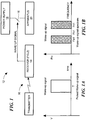
- a transmitter 10 for transmitting a wake up signal to a remote station 12.
- the remote station 12 includes a receiver 14 ( FIG. 2 ) which operates with low power and in response to the detection of the transmitted wake up signal may, here for example, activate a switch 16 turn couple a power supply 18 for other apparatus 20 at the remote location.
- the transmitter wake up signal is encoded with a predetermined signature.
- the signature is a pulse ( FIG. 1A ) having two spaced carrier frequencies, f a and f c . More particularly the time history of the encoded transmitted signal or pulse is shown in FIG. 1A and the frequency spectrum of the two RF carrier frequency signals f a and f c is shown in FIG. 1B .
- the transmitted encoded signal ( FIG. 1A ), having a pair of spaced predetermined frequencies, f a and f c separated by a predetermined frequency, f b , ( FIG. 1B ) is received by the receiver 14 along with unwanted signals, such as noise or other interfering signals, such unwanted signals having frequencies extending over the pair of spaced predetermined frequencies, f a and f c .
- unwanted signals such as noise or other interfering signals
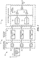
- the receiver 14 ( FIG. 2 ) includes a front end section having an antenna and impedance matching network 20 having an antenna 22 and an impedance matching network 24, arranged as shown,
- the receiver 14 includes a narrow band filter section 26 having three narrow band filters 26a, 26b and 26c; a pair of the filters, here filters 26a and 26c being tuned to a corresponding one of the paired predetermined frequencies, f a and f c , respectively, (filter 26a being tuned to the frequency f a and filter 26c being tuned to the frequency f c ) and a third one of the filters 26b being tuned to the third predetermined frequency, f b , between the pair of frequencies.
- the receiver 14 includes a detection section 28 having three detector circuits, 28a, 28b and 28c, each one of the detector circuits 28a-28c being fed by a corresponding one of the three narrow band filters 26a, 26b and 26c, respectively as shown, for producing an output representative of the amount of energy, which is a function of detected peak voltage, received by such one of the three narrow band filters 26a, 26b and 26c, respectively fed thereto, the energy in the third predetermined frequency providing a reference signal representative of the level of the unwanted signals having frequencies included over the pair of spaced predetermined frequencies.
- detector circuit 28 a is fed by filter 26a
- detector circuit 28b is fed by filter 26b
- detector circuit 28c is fed by filter 28c; with the energy detected by circuit 28b representing the amount of energy in the third predetermined frequency, f b , and thereby provides a reference signal representative of the level of the unwanted signals having frequencies included over the pair of spaced predetermined frequencies.
- Each one of the detector circuits 28a-28c is identical in construction; an exemplary one thereof, here detector circuit 28a being shown in detail in FIG. 3 .
- the detector circuit 28a is an n-stage rectifier circuit and includes 2N, where N is an integer greater than 1, diodes Dl-D2N and capacitors C1-CN and coupling capacitors C C1 - C CN , arranged as shown to produce an output N times the peak voltage, V peak , of the signal produced at the output of the narrow band filter 26a. More particularly, the output from the narrow band filter 26a is fed, in parallel to N, serially connected, coupling capacitors C C1 - C CN , each of which store the peak voltage, V peak , of the signal passing through narrow band filter 26a. The voltage V peak on capacitor C C1 is coupled through diode D2 to capacitor C 1 .
- V peak of the signal passing through the narrow band filter 28a passes through diodes D2; however, the total voltage stored on capacitor C 2 is the sum of the peak voltages stored on capacitor C 1 and C 2 ; i.e., 2 V peak .
- the capacitor C N stores N V peak . It is noted the peak voltage V peak is representative of the energy in the signals passing through the narrow band filters 28a-28c.
- the receiver 14 ( FIG. 2 ) also includes a detection/logic section 27 for detecting the reception of the encoded signal as a function of the level of the energy in pair of the filters tuned to a corresponding one of the paired predetermined frequencies relative to the energy in the third one of the pair of filters.
- More particularly detection/logic section 27 includes a pair of comparators 30 1 , 30 2 ; a first one of the comparators 30 1 being fed by: one of the detector section 28a-28c fed by the one of the narrow band filters 26a- 26c fed by the signal having the predetermined frequency f a , and the one of the detector section 28a-28c fed by the one of the narrow band filters 26a-26c fed by the signal having the predetermined frequency f b , for producing an output logic signal indicating whether the amount of energy in the one of the narrow band filters fed by the signal having the predetermined frequency f a , is greater than the amount of energy in the one of the narrow band filters fed by the signal having the predetermined frequency f b .
- comparator 30 1 is fed by detector circuits 28a and 28b; with the + input being coupled to the output of detector circuit 28a and the - input being coupled to detector circuit 28b, as shown.
- a second one of the comparators 30 2 is fed by: the one of the detector section 28a-28c fed by the one of the narrow band filters 26a-26c fed by the signal having the predetermined frequency f c , and the one of the detector section 28a-28c fed by the one of the narrow band filters 26a-26c fed by the signal having the predetermined frequency f b , for producing an output logic signal indicating whether the amount of energy in the one of the narrow band filters 26a-26c fed by the signal having the predetermined frequency f c is greater than the amount of energy in the one of the narrow band filters fed by the signal having the predetermined frequency, f b .
- comparator 30 2 is fed by detector circuits 28c and 28b; with the + input being coupled to the output detector circuit 28c and the - input being coupled to detector circuit 28b, as shown.
- the receiver 10 also includes a logic network fed by the output logic signal produced by first one of the comparators and the logic signal produced by the second one of the comparators, for indication detection of the signal.
- the logic network indicates detection of the encoded signal as a function of whether both: the logic signal produced by the first comparator indicated that the amount of energy in the one of the narrow band filters fed by the signal having the predetermined frequency f a , is greater than the amount of energy in the one of the narrow band filters fed by the signal having the predetermined frequency f b ; and the logic signal produced by the second comparator indicated that the amount of energy in the one of the narrow band filters fed by the signal having the predetermined frequency f c is greater than the amount of energy in the one of the narrow band filters fed by the signal having the predetermined frequency f c .
- comparator 30 2 is fed by detector circuit 26c and 26b; with the + input being coupled to the output of detector circuit 28c and the - input being coupled to detector circuit 28b, as shown.
- a logic network 32 is provided having, here for example, a pair of Schmitt triggers 34a, 34b, each one fed by a corresponding one of the pair of comparators 34 1 , 34 2 , respectively as shown.
- a NOR gate 36 is fed by the outputs of the pair of Schmitt triggers 34a, 34b.
- the Schmitt triggers 34 1 and 34 2 convert a logic 1 fed thereto to a logic 0 signal and conversely converts a logic 0 signal to a logic 1 signal.
- a logic 1 signal is produced by NOR gate only if a logic 1 is produced by both comparator 30 1 and comparator 30 2 .
- a wake up signal is produced only by a logic 1 signal at the output of the NOR gate 36.
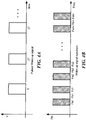
- a receiver 14' for detecting an encoded signal ( FIG. 4A ) having time sequence of M pulses P m , where M is an integer, each one of the M pulses, P m , includes a lower predetermined frequency, f am ( FIG. 4B ), and a predetermined upper frequency f cm , the predetermined lower frequency, f am , and the predetermined upper frequency f cm being separated in frequency by a predetermined third frequency, f bm , where f cm >f bm >f am .
- the receiver sensitivity is improved by utilizing multiple wake-up signal pulses, here M pulses and set of three narrow band filter for the frequencies in each one of the pluses.
- band pass filter section 26'a includes M narrow band filters 26' fa1 - faM , each one tuned to a corresponding one of the frequencies fa 1 -fa M , respectively;
- band pass filter section 28'b includes M narrow band filters 26' fb1 - fbM , each one tuned to a corresponding one of the frequencies fb 1 -fb M , respectively;
- section 28c includes M narrow band filters includes M narrow band filters 26' fc1-fcM , each one tuned to a corresponding one of the frequencies fc 1 -fc M , respectively, as shown.
- the outputs of the band pass filter sections 26'a-26'c are fed to a corresponding one of three detector sections 28'a-28'c, respectively, as shown.
- Each one of the detector sections 28'a -28'c is identical in construction and an exemplary one thereof, here section 28'a is shown in detail in FIG. 6 .
- detection section 28'a has M inputs, each one being fed by a corresponding one of the M band pass filters 26' fa1 -26' faM , fed thereto.
- the section 28'a is also an n-stage rectifier circuit and includes M coupling capacitors C C1 -C CM , 2M diodes D 1 -D 2M and capacitors C 1 -C M arranged as shown to sum the peak voltages V peak1 - V peakM of each one the outputs of the M band pass filters 26' fa1 -26' faM , respectively, fed thereto, as indicated.
- the voltage at the capacitor C M equals: V peak1 + V peak2 + ... V peakM .
- detection/logic section 27 includes a pair of comparators 30 1 , 30 2 ; a first one of the comparators 30 1 being fed by: one of the detector sections 28'a and 28'b. More particularly, comparator 30' 1 is fed by detector circuits 28'a and 28'b; with the + input being coupled to the output of detector circuit 28'a and the - input being coupled to detector circuit 28b', as shown. A second one of the comparators 30' 2 is fed by detector section 28b' and detector section 28c' with the + input being coupled to the output of detector circuit 28'c and the - input being coupled to detector circuit 28'b, as shown.
- the receiver 14' also includes a logic network fed by the output logic signal produced by first one of the comparators and the logic signal produced by the second one of the comparators, for indication detection of the signal.
- the logic network indicates detection of the encoded signal as a function of whether both: the logic signal produced by the first comparator indicated that the amount of energy in the one of the narrow band filters fed by the signal having the predetermined frequency f a , is greater than the amount of energy in the one of the narrow band filters fed by the signal having the predetermined frequency f b ; and the logic signal produced by the second comparator indicated that the amount of energy in the one of the narrow band filters fed by the signal having the predetermined frequency f c is greater than the amount of energy in the one of the narrow band filters fed by the signal having the predetermined frequency f c .
- comparator 30 2 is fed by detector circuit 26c and 26b; with the + input being coupled to the output of detector circuit 28c and the - input being coupled to detector circuit 28b, as shown.
- a logic network 32 is provided having, here for example, a pair of Schmitt triggers 34a, 34b, each one fed by a corresponding one of the pair of comparators 34 1 , 34 2 , respectively as shown.
- a NOR gate 36 is fed by the outputs of the pair of Schmitt triggers 34a, 34b.
- the Schmitt triggers 34 1 and 34 2 convert a logic 1 fed thereto to a logic 0 signal and conversely converts a logic 0 signal to a logic 1 signal.
- a logic 1 signal is produced by NOR gate only if a logic 1 is produced by both comparator 30 1 and comparator 30 2 .
- a wake up signal is produced only by a logic 1 signal at the output of the NOR gate 36.
- the receivers include: (A) three narrow band filter sections, each one of the three narrow band filter sections having M narrow band filters, each one the M narrow filters in each one of the three narrow band filter sections being tuned to a corresponding one of the three predetermined frequencies, f cm , f bm , and f am; (B) three detector sections; a first one of the three detector sections being fed by the M narrow band filters tuned to the predetermined frequencies f am; a second one of the three detector sections being fed by the M narrow band filters tuned to the predetermined frequencies f bm , and a third one of the three detector sections being fed by the M narrow band filters tuned to the predetermined frequencies f cm ; wherein each one of the three detector sections includes: M detector circuits, each one of the M detector circuits being fed a corresponding one of the M narrow band filters in the one of the narrow band filter sections fed thereto; each one of the three detection sections includes circuity for summing peak voltages of each one the outputs of the M band pass filter fed thereto;
- a method for detecting a signal comprising: encoding the signal with a pair of spaced predetermined frequencies; and detecting energy in each of the pair of predetermined frequencies and in a predetermined frequency between the pair of predetermined frequencies.
- the method includes comparing energy detected in each of the pair of predetermined frequencies with the energy detected in the predetermined frequency between the pair of predetermined frequencies.
- the detecting comprises passing the encoded signal through narrow band filters, each one of the filters being tuned to a corresponding one of the pair of predetermined frequencies and the predetermined frequency between the pair of predetermined frequencies. More particularly, the detecting comprises passing outputs from the narrow band filters to a corresponding rectifier circuit. Still more particularly, the detecting comprises passing outputs of the rectifiers circuits to a comparator section for comparing energy passing through the filters being tuned to the pair of predetermined frequencies with energy passing through the filter tuned to the predetermined frequency between the pair of predetermined frequencies.
- a receiver for detecting an encoded signal, having a pair of spaced predetermined frequencies, in the presence of unwanted signals having frequencies extending over the pair of spaced predetermined frequencies includes: three narrow band filters, a pair of the filters being tuned to the paired predetermined frequencies for receiving energy from the encoded signal and a third one of the filters being tuned to a third predetermined frequency between the pair of frequencies for receiving energy from a portion of the unwanted signals; and a detection section for indicating detection of the encoded signal as a function of the energy in the pair of filters tuned to the paired predetermined frequencies relative to the energy in the third one of the three filters, the energy in the third one of the three filters indicating a level of the unwanted signals having frequencies included over the pair of spaced predetermined frequencies.
- a receiver for detecting an encoded signal, having a pair of spaced predetermined frequencies, in the presence of unwanted signals having frequencies extending over the pair of spaced predetermined frequencies includes: three narrow band filters, a pair of the filters being tuned to a corresponding one of the paired predetermined frequencies and a third one of the filters being tuned to a third predetermined frequency between the pair of frequencies; three detector sections, each one of the detector sections being fed by a corresponding one of the three narrow band filters for producing an output representative of the amount of energy received by such one of the three narrow band filters fed thereto, the energy in the third predetermined frequency providing a reference signal representative of the level of the unwanted signals having frequencies included over the pair of spaced predetermined frequencies; and a logic section for detecting the reception of the encoded signal as a function of the level of the energy in the pair of filters tuned to a corresponding one of the paired predetermined frequencies relative to the energy in the third one of the pair of filters.
- the receiver may include one or more of the following features independently or in combination with another feature to include: wherein pair of predetermined frequencies are f a and f c and the third predetermined frequency is f b , where f c >f b >f a and the logic section comprises a pair of comparators, a first one of the comparators being fed by: one of the detector section fed by the one of the narrow band filters fed by the signal having the predetermined frequency f a , and the one of the detector section fed by the one of the narrow band filters fed by the signal having the predetermined frequency f b , for producing an output logic signal indicating whether the amount of energy in the one of the narrow band filters fed by the signal having the predetermined frequency f a , is greater than the amount of energy in the one of the narrow band filters fed by the signal having the predetermined frequency f b and a second one of the comparators being fed by: the one of the detector section fed by the one of the narrow band filters fed by the signal having the predetermined frequency f c
- each one of the M pulses, P m includes a lower predetermined frequency, f am , and a predetermined upper frequency f cm , the predetermined lower frequency, f am , and the predetermined upper frequency f cm being separated in frequency by a predetermined third frequency, f bm , where f cm >f bm >f am , according to the disclosure includes: (A) three narrow band filter sections, each one of the three narrow band filter sections having M narrow band filters, each one the M narrow filters in each one of the three narrow band filter sections being tuned to a corresponding one of the three predetermined frequencies, f cm , f bm , and f am; (B) three detector sections, a first one of the three detector sections being fed by the M narrow band filters tuned to the predetermined frequencies f am , a second one of the three detector sections being fed by the M narrow band filters tuned
- a method for detecting a signal includes: encoding the signal with a pair of spaced predetermined frequencies; and detecting energy in each of the pair of predetermined frequencies and in a predetermined frequency between the pair of predetermined frequencies.
- the method may include one or more of the following features independently or in combination with another feature to include: comparing energy detected in each of the pair of predetermined frequencies with the energy detected in the predetermined frequency between the pair of predetermined frequencies; wherein the detecting comprises passing the encoded signal through narrow band filters, each one of the filters being tuned to a corresponding one of the pair of predetermined frequencies and the predetermined frequency between the pair of predetermined frequencies; wherein the detecting comprises passing outputs from the narrow band filters to a corresponding rectifier circuit; and wherein the detecting comprises passing outputs of the rectifiers circuits to a comparator section for comparing energy passing through the filters being tuned to the pair of predetermined frequencies with energy passing through the filter tuned to the predetermined frequency between the pair of predetermined frequencies.
Landscapes
- Engineering & Computer Science (AREA)
- Computer Networks & Wireless Communication (AREA)
- Signal Processing (AREA)
- Physics & Mathematics (AREA)
- Nonlinear Science (AREA)
- Circuits Of Receivers In General (AREA)
Claims (12)
- Empfänger (14) zum Erkennen eines codierten Signals mit einem Paar beabstandeter vorbestimmter Frequenzen bei Vorhandensein unerwünschter Signale mit Frequenzen, die sich über das Paar beabstandeter vorbestimmter Frequenzen erstrecken, wobei der Empfänger umfasst:drei Schmalbandfilter (26a, 26b, 26c), wobei ein Paar der Filter (26a, 26c) auf die gepaarten vorbestimmten Frequenzen abgestimmt ist, um Energie aus dem codierten Signal zu empfangen, und ein drittes der Filter (26b) auf eine dritte vorbestimmte Frequenz zwischen dem Paar von Frequenzen abgestimmt ist, um Energie aus einem Abschnitt der unerwünschten Signale zu empfangen; undeinen Erkennungsabschnitt (28, 27) zum Anzeigen der Erkennung des codierten Signals in Abhängigkeit von der Energie in dem Paar von Filtern (26a, 26c), die auf die gepaarten vorbestimmten Frequenzen relativ zur Energie in dem dritten der drei Filter (26b) abgestimmt sind, wobei die Energie in dem dritten der drei Filter (26b) einen Pegel der unerwünschten Signale mit über das Paar von beabstandeten vorbestimmten Frequenzen enthaltenen Frequenzen anzeigt.
- Empfänger (14) nach Anspruch 1, wobei der Erkennungsabschnitt (28, 27) umfasst:drei Detektorabschnitte (28a, 28b, 28c), wobei jeder der Detektorabschnitte (28a, 28b, 28c) durch ein entsprechendes der drei Schmalbandfilter (26a, 26b, 26c) gespeist wird, um ein Ausgangssignal zu erzeugen, das für die Energiemenge repräsentativ ist, die durch eines der drei zugespeisten Schmalbandfilter (26a, 26b, 26c) empfangen wird, wobei die Energie in der dritten vorbestimmten Frequenz ein Referenzsignal liefert, das für den Pegel der unerwünschten Signale mit enthaltenen Frequenzen über dem Paar beabstandeter vorbestimmter Frequenzen repräsentativ ist; undeinen Logikabschnitt (27) zum Erkennen des Empfangs des codierten Signals in Abhängigkeit von dem Pegel der Energie in dem Paar von Filtern, die auf eine entsprechende der gepaarten vorbestimmten Frequenzen relativ zur Energie in dem dritten des Paares von Filtern abgestimmt sind.
- Empfänger nach Anspruch 2, wobei das Paar vorbestimmter Frequenzen fa und fc sind und die dritte vorbestimmte Frequenz fb ist, wobei fc>fb>fa und der Logikabschnitt umfasst:ein Paar von Komparatoren,wobei ein erster der Komparatoren gespeist wird durch: einen der Detektorabschnitte, der durch das eine der Schmalbandfilter gespeist wird, das durch das Signal mit der vorbestimmten Frequenz fa gespeist wird, und den einen der Detektorabschnitte, der durch das eine der Schmalbandfilter gespeist wird, das durch das Signal mit der vorbestimmten Frequenz fb gespeist wird, um ein logisches Ausgangssignal zu erzeugen, das anzeigt, ob die Energiemenge in dem einen der Schmalbandfilter, das durch das Signal mit der vorbestimmten Frequenz fa gespeist wird, größer als die Energiemenge in dem einen der Schmalbandfilter ist, das durch das Signal mit der vorbestimmten Frequenz fb gespeist wird; undwobei ein zweiter der Komparatoren gespeist wird durch: einen der Detektorabschnitte, der durch das eine der Schmalbandfilter gespeist wird, das durch das Signal mit der vorbestimmten Frequenz fc gespeist wird, und den einen der Detektorabschnitte, der durch das eine der Schmalbandfilter gespeist wird, das durch das Signal mit der vorbestimmten Frequenz fb gespeist wird, um ein logisches Ausgangssignal zu erzeugen, das angibt, ob die Energiemenge in dem einen der Schmalbandfilter, das durch das Signal mit der vorbestimmten Frequenz fc gespeist wird, größer als die Energiemenge in dem einen der Schmalbandfilter ist, das durch das Signal mit der vorbestimmten Frequenz gespeist wird; undein Logiknetzwerk, das durch das durch den ersten der Komparatoren erzeugte logische Ausgangssignal und das durch den zweiten der Komparatoren erzeugte logische Signal gespeist wird, zur Anzeigeerkennung des Signals.
- Empfänger nach Anspruch 3, wobei das Logiknetzwerk die Erkennung des codierten Signals in Abhängigkeit davon anzeigt, ob sowohl: das durch den ersten Komparator erzeugte logische Signal anzeigt, dass die Energiemenge in dem einen der Schmalbandfilter, das durch das Signal mit der vorbestimmten Frequenz fa gespeist wird, größer als die Energiemenge in dem einen der Schmalbandfilter ist, das durch das Signal mit der vorbestimmten Frequenz fb gespeist wird; als auch das durch den zweiten Komparator erzeugte Logiksignal anzeigt, dass die Energiemenge in dem einen der Schmalbandfilter, das durch das Signal mit der vorbestimmten Frequenz fb gespeist wird, größer als die Energiemenge in dem einen der Schmalbandfilter ist, das durch das Signal mit der vorbestimmten Frequenz fc gespeist wird.
- Empfänger (14) zum Erkennen eines codierten Signals mit einer Zeitsequenz von M Impulsen Pm, wobei M eine ganze Zahl ist, jeder der M Impulse Pm eine vorbestimmte untere Frequenz fam und eine vorbestimmte obere Frequenz fcm aufweist, wobei die vorbestimmte untere Frequenz fam und die vorbestimmte obere Frequenz fcm frequenzmäßig durch eine vorbestimmte dritte Frequenz fbm getrennt sind, wobei fcm>fbm>fam, wobei der Empfänger (14) umfasst:(A) drei Schmalbandfilterabschnitte (26'A, 26'B, 26'C), wobei jeder der drei Schmalbandfilterabschnitte (26'A, 26'B, 26'C) M Schmalbandfilter (26) aufweist, wobei jedes der M Schmalbandfilter (26) in jedem der drei Schmalbandfilterabschnitte auf eine entsprechende der drei vorbestimmten Frequenzen fcm, fbm und fam abgestimmt ist;(B) drei Detektorabschnitte (28'a, 28'b, 28'c),jeder der drei Detektorabschnitte (28'a, 28'b, 28'c) umfasst:wobei ein erster der drei Detektorabschnitte (28'a) durch die M Schmalbandfilter (26) gespeist wird, die auf die vorbestimmten Frequenzen fam abgestimmt sind,wobei ein zweiter der drei Detektorabschnitte (28'b) durch die M Schmalbandfilter (26) gespeist wird, die auf die vorbestimmten Frequenzen fbm abgestimmt sind, undwobei ein dritter der drei Detektorabschnitte (28'c) durch die M Schmalbandfilter (26) gespeist wird, die auf die vorbestimmten Frequenzen fcm abgestimmt sind; wobeiM Detektorschaltungen, wobei jeder der M Detektorschaltungen ein entsprechendes der M Schmalbandfilter in dem einen der ihr zugespeisten Schmalbandfilterabschnitte zugespeist wird; wobei jeder der drei Detektorabschnitte (28'a, 28'b, 28'c) eine Schaltungsanordnung zum Summieren der Spitzenspannungen jedes der Ausgänge der zugespeisten M Bandpassfilter aufweist;(C) ein Paar von Komparatoren (301, 302),wobei ein erster des Paars von Komparatoren (301) durch den ersten der drei Detektorabschnitte (28'a) und den zweiten der drei Detektorabschnitte (28'b) gespeist wird, um ein logisches Ausgangssignal zu erzeugen, das anzeigt, ob die Energiemenge in den M Schmalbandfiltern (26), die auf die Frequenzen fam abgestimmt sind, größer als die Energiemenge in den M Schmalbandfiltern ist, die auf die Frequenzen fbm abgestimmt sind; undwobei ein zweiter des Paars von Komparatoren (302) durch den dritten der drei Detektorabschnitte (28'c) und den zweiten der drei Detektorabschnitte (28'b) gespeist wird, um ein logisches Ausgangssignal zu erzeugen, das anzeigt, ob die Energiemenge in den M Schmalbandfiltern (26), die auf die Frequenzen fcm abgestimmt sind, größer als die Energiemenge in den M Schmalbandfiltern ist, die auf die Frequenzen fbm abgestimmt sind; und(D) ein Logiknetzwerk (32), das durch das durch den ersten der Komparatoren erzeugte logische Ausgangssignal (301) und das durch den zweiten der Komparatoren (302) erzeugte logische Signal gespeist wird, zur Anzeigeerkennung des codierten Signals, wenn sowohl: (a) das durch den ersten Komparator erzeugte logische Signal anzeigte, dass Energiemenge in der Energiemenge in den M Schmalbandfiltern (26), die auf die Frequenzen fam abgestimmt sind, größer als die Energiemenge in den M Schmalbandfiltern (26) ist, die auf die Frequenzen fbm abgestimmt sind; und (b) die Energiemenge in den M Schmalbandfiltern (26), die auf die Frequenzen fcm abgestimmt sind, größer als die Energiemenge in den M Schmalbandfiltern (26) ist, die auf die Frequenzen fbm abgestimmt sind.
- Empfänger nach Anspruch 1, wobei der Erkennungsabschnitt Gleichrichterschaltungen aufweist.
- Empfänger nach Anspruch 2, wobei der Logikabschnitt Gleichrichterschaltungen aufweist.
- Empfänger nach Anspruch 3, wobei der Logikabschnitt Gleichrichterschaltungen aufweist.
- Empfänger nach Anspruch 4, wobei die Detektorschaltungen Gleichrichterschaltungen aufweisen.
- Empfänger nach Anspruch 7, wobei die Gleichrichterschaltungen mehrstufige Gleichrichterschaltungen sind.
- Empfänger nach Anspruch 8, wobei die Gleichrichterschaltungen mehrstufige Gleichrichterschaltungen sind.
- Empfänger nach Anspruch 9, wobei die Gleichrichterschaltungen mehrstufige Gleichrichterschaltungen sind.
Applications Claiming Priority (2)
| Application Number | Priority Date | Filing Date | Title |
|---|---|---|---|
| US14/812,283 US9634703B2 (en) | 2015-07-29 | 2015-07-29 | Low power encoded signal detection |
| PCT/US2016/041857 WO2017019290A1 (en) | 2015-07-29 | 2016-07-12 | Low power encoded signal detection |
Publications (2)
| Publication Number | Publication Date |
|---|---|
| EP3329596A1 EP3329596A1 (de) | 2018-06-06 |
| EP3329596B1 true EP3329596B1 (de) | 2020-08-19 |
Family
ID=56684235
Family Applications (1)
| Application Number | Title | Priority Date | Filing Date |
|---|---|---|---|
| EP16751053.6A Active EP3329596B1 (de) | 2015-07-29 | 2016-07-12 | Erkennung von codierten niedrigleistungssignalen |
Country Status (4)
| Country | Link |
|---|---|
| US (1) | US9634703B2 (de) |
| EP (1) | EP3329596B1 (de) |
| CN (1) | CN108028644B (de) |
| WO (1) | WO2017019290A1 (de) |
Cited By (1)
| Publication number | Priority date | Publication date | Assignee | Title |
|---|---|---|---|---|
| US20230259078A1 (en) * | 2020-06-12 | 2023-08-17 | Korea Electrotechnology Research Institute | Temperature discretization digital device |
Families Citing this family (2)
| Publication number | Priority date | Publication date | Assignee | Title |
|---|---|---|---|---|
| US9652963B2 (en) * | 2015-07-29 | 2017-05-16 | Dell Products, Lp | Provisioning and managing autonomous sensors |
| CN111431559B (zh) * | 2020-04-29 | 2022-07-15 | 瑞美达电子(深圳)有限公司 | 一种物联网唤醒、数据传输装置及方法 |
Family Cites Families (6)
| Publication number | Priority date | Publication date | Assignee | Title |
|---|---|---|---|---|
| US5185591A (en) * | 1991-07-12 | 1993-02-09 | Abb Power T&D Co., Inc. | Power distribution line communication system for and method of reducing effects of signal cancellation |
| FI99166C (fi) * | 1994-10-14 | 1997-10-10 | Nokia Telecommunications Oy | Menetelmä ennalta määrätyn taajuisen signaalin detektoimiseksi sekä ilmaisinpiiri |
| EP1081870A1 (de) | 1999-09-03 | 2001-03-07 | Sony International (Europe) GmbH | Rauschdetektion in einem frequenzdemodulierten FM-Rundfunkaudiosignal |
| WO2007034366A2 (en) * | 2005-09-19 | 2007-03-29 | Nxp B.V. | Data communication circuit with equalization control |
| JP2008199209A (ja) | 2007-02-09 | 2008-08-28 | Matsushita Electric Ind Co Ltd | 無線受信装置 |
| JP4535145B2 (ja) | 2008-02-26 | 2010-09-01 | ソニー株式会社 | 通信装置、ノイズ除去方法、およびプログラム |
-
2015
- 2015-07-29 US US14/812,283 patent/US9634703B2/en active Active
-
2016
- 2016-07-12 WO PCT/US2016/041857 patent/WO2017019290A1/en not_active Ceased
- 2016-07-12 EP EP16751053.6A patent/EP3329596B1/de active Active
- 2016-07-12 CN CN201680053576.1A patent/CN108028644B/zh active Active
Non-Patent Citations (1)
| Title |
|---|
| None * |
Cited By (2)
| Publication number | Priority date | Publication date | Assignee | Title |
|---|---|---|---|---|
| US20230259078A1 (en) * | 2020-06-12 | 2023-08-17 | Korea Electrotechnology Research Institute | Temperature discretization digital device |
| US12517477B2 (en) * | 2020-06-12 | 2026-01-06 | Korea Electrotechnology Research Institute | Temperature discretization digital device |
Also Published As
| Publication number | Publication date |
|---|---|
| US20170033817A1 (en) | 2017-02-02 |
| CN108028644A (zh) | 2018-05-11 |
| EP3329596A1 (de) | 2018-06-06 |
| CN108028644B (zh) | 2021-07-13 |
| US9634703B2 (en) | 2017-04-25 |
| WO2017019290A1 (en) | 2017-02-02 |
Similar Documents
| Publication | Publication Date | Title |
|---|---|---|
| Bagwari et al. | Comparison between adaptive double-threshold based energy detection and cyclostationary detection technique for cognitive radio networks | |
| EP3329596B1 (de) | Erkennung von codierten niedrigleistungssignalen | |
| EP3306349A3 (de) | Systeme und verfahren zur ais-transponder-integration mit ils/vor-empfängern | |
| RU2019115832A (ru) | Оптимизированное сочетание преамбулы и полей данных для сетей датчиков, имеющих низкое потребление электричества, на основе способа разделения телеграмм | |
| WO2013064835A3 (en) | Communication apparatus and method | |
| KR102036081B1 (ko) | 펄스 위치변조를 이용한 전력선 통신방법 및 장치 | |
| JP2018007240A (ja) | Rfid受信装置および無線信号に符合化されたデータビットを抽出する方法 | |
| JP2008298596A (ja) | Dme地上装置 | |
| US9064396B2 (en) | Receiver, apparatus, and methods for wirelessly receiving data from a power infrastructure | |
| RU2011109037A (ru) | Способ обнаружения проникновения коротковолнового радиосигнала в систему передачи данных по линии электропередач и модем передачи данных по линии электропередач | |
| MX2020012067A (es) | Deteccion del canal fisico de acceso aleatorio (prach) rentable. | |
| CN107852193A (zh) | 接收由双态符号序列调制相位或频率的信号的方法和设备 | |
| KR101060303B1 (ko) | Ook 및 fsk 이중 모드 복조 방법 및 장치 | |
| US8111781B2 (en) | Radio frequency identification (RFID) interrogators | |
| US20080001731A1 (en) | Multi-frequency alarm system receiver with interference detection | |
| WO2016079534A1 (en) | Am demodulation with phase and symbol edge detection | |
| GB2314237A (en) | Communications system | |
| JP6229518B2 (ja) | 無線受信装置及び無線受信方法 | |
| US11363531B2 (en) | Encoding and decoding data in communication frames of a communications protocol | |
| KR101543016B1 (ko) | 송수신 장치 | |
| JP6382130B2 (ja) | 無線受信装置及び無線受信方法 | |
| US9595984B2 (en) | Concept for transmitting and receiving an information symbol | |
| US8837560B2 (en) | Method and device for the contactless transmission of electrical power and information | |
| EP0813318B1 (de) | Punkt zur Mehrpunktzweiwegübertragungsanordnung mit Frequenzwahl für Basisstation | |
| Didkowsky et al. | Symbol timing synchronization with the usage of Barker sequences in communication systems utilizing stochastic signals |
Legal Events
| Date | Code | Title | Description |
|---|---|---|---|
| STAA | Information on the status of an ep patent application or granted ep patent |
Free format text: STATUS: THE INTERNATIONAL PUBLICATION HAS BEEN MADE |
|
| PUAI | Public reference made under article 153(3) epc to a published international application that has entered the european phase |
Free format text: ORIGINAL CODE: 0009012 |
|
| STAA | Information on the status of an ep patent application or granted ep patent |
Free format text: STATUS: REQUEST FOR EXAMINATION WAS MADE |
|
| 17P | Request for examination filed |
Effective date: 20180206 |
|
| AK | Designated contracting states |
Kind code of ref document: A1 Designated state(s): AL AT BE BG CH CY CZ DE DK EE ES FI FR GB GR HR HU IE IS IT LI LT LU LV MC MK MT NL NO PL PT RO RS SE SI SK SM TR |
|
| AX | Request for extension of the european patent |
Extension state: BA ME |
|
| RIN1 | Information on inventor provided before grant (corrected) |
Inventor name: LARDIZABAL, STEVEN, M. Inventor name: WANG, ZHAOYANG, C. |
|
| DAV | Request for validation of the european patent (deleted) | ||
| DAX | Request for extension of the european patent (deleted) | ||
| GRAP | Despatch of communication of intention to grant a patent |
Free format text: ORIGINAL CODE: EPIDOSNIGR1 |
|
| STAA | Information on the status of an ep patent application or granted ep patent |
Free format text: STATUS: GRANT OF PATENT IS INTENDED |
|
| INTG | Intention to grant announced |
Effective date: 20200219 |
|
| GRAS | Grant fee paid |
Free format text: ORIGINAL CODE: EPIDOSNIGR3 |
|
| GRAA | (expected) grant |
Free format text: ORIGINAL CODE: 0009210 |
|
| STAA | Information on the status of an ep patent application or granted ep patent |
Free format text: STATUS: THE PATENT HAS BEEN GRANTED |
|
| AK | Designated contracting states |
Kind code of ref document: B1 Designated state(s): AL AT BE BG CH CY CZ DE DK EE ES FI FR GB GR HR HU IE IS IT LI LT LU LV MC MK MT NL NO PL PT RO RS SE SI SK SM TR |
|
| REG | Reference to a national code |
Ref country code: CH Ref legal event code: EP |
|
| REG | Reference to a national code |
Ref country code: DE Ref legal event code: R096 Ref document number: 602016042308 Country of ref document: DE |
|
| REG | Reference to a national code |
Ref country code: AT Ref legal event code: REF Ref document number: 1305117 Country of ref document: AT Kind code of ref document: T Effective date: 20200915 |
|
| REG | Reference to a national code |
Ref country code: IE Ref legal event code: FG4D |
|
| REG | Reference to a national code |
Ref country code: LT Ref legal event code: MG4D |
|
| REG | Reference to a national code |
Ref country code: NL Ref legal event code: MP Effective date: 20200819 |
|
| PG25 | Lapsed in a contracting state [announced via postgrant information from national office to epo] |
Ref country code: GR Free format text: LAPSE BECAUSE OF FAILURE TO SUBMIT A TRANSLATION OF THE DESCRIPTION OR TO PAY THE FEE WITHIN THE PRESCRIBED TIME-LIMIT Effective date: 20201120 Ref country code: BG Free format text: LAPSE BECAUSE OF FAILURE TO SUBMIT A TRANSLATION OF THE DESCRIPTION OR TO PAY THE FEE WITHIN THE PRESCRIBED TIME-LIMIT Effective date: 20201119 Ref country code: HR Free format text: LAPSE BECAUSE OF FAILURE TO SUBMIT A TRANSLATION OF THE DESCRIPTION OR TO PAY THE FEE WITHIN THE PRESCRIBED TIME-LIMIT Effective date: 20200819 Ref country code: LT Free format text: LAPSE BECAUSE OF FAILURE TO SUBMIT A TRANSLATION OF THE DESCRIPTION OR TO PAY THE FEE WITHIN THE PRESCRIBED TIME-LIMIT Effective date: 20200819 Ref country code: PT Free format text: LAPSE BECAUSE OF FAILURE TO SUBMIT A TRANSLATION OF THE DESCRIPTION OR TO PAY THE FEE WITHIN THE PRESCRIBED TIME-LIMIT Effective date: 20201221 Ref country code: NO Free format text: LAPSE BECAUSE OF FAILURE TO SUBMIT A TRANSLATION OF THE DESCRIPTION OR TO PAY THE FEE WITHIN THE PRESCRIBED TIME-LIMIT Effective date: 20201119 Ref country code: FI Free format text: LAPSE BECAUSE OF FAILURE TO SUBMIT A TRANSLATION OF THE DESCRIPTION OR TO PAY THE FEE WITHIN THE PRESCRIBED TIME-LIMIT Effective date: 20200819 Ref country code: SE Free format text: LAPSE BECAUSE OF FAILURE TO SUBMIT A TRANSLATION OF THE DESCRIPTION OR TO PAY THE FEE WITHIN THE PRESCRIBED TIME-LIMIT Effective date: 20200819 |
|
| REG | Reference to a national code |
Ref country code: AT Ref legal event code: MK05 Ref document number: 1305117 Country of ref document: AT Kind code of ref document: T Effective date: 20200819 |
|
| PG25 | Lapsed in a contracting state [announced via postgrant information from national office to epo] |
Ref country code: RS Free format text: LAPSE BECAUSE OF FAILURE TO SUBMIT A TRANSLATION OF THE DESCRIPTION OR TO PAY THE FEE WITHIN THE PRESCRIBED TIME-LIMIT Effective date: 20200819 Ref country code: NL Free format text: LAPSE BECAUSE OF FAILURE TO SUBMIT A TRANSLATION OF THE DESCRIPTION OR TO PAY THE FEE WITHIN THE PRESCRIBED TIME-LIMIT Effective date: 20200819 Ref country code: LV Free format text: LAPSE BECAUSE OF FAILURE TO SUBMIT A TRANSLATION OF THE DESCRIPTION OR TO PAY THE FEE WITHIN THE PRESCRIBED TIME-LIMIT Effective date: 20200819 Ref country code: PL Free format text: LAPSE BECAUSE OF FAILURE TO SUBMIT A TRANSLATION OF THE DESCRIPTION OR TO PAY THE FEE WITHIN THE PRESCRIBED TIME-LIMIT Effective date: 20200819 Ref country code: IS Free format text: LAPSE BECAUSE OF FAILURE TO SUBMIT A TRANSLATION OF THE DESCRIPTION OR TO PAY THE FEE WITHIN THE PRESCRIBED TIME-LIMIT Effective date: 20201219 |
|
| PG25 | Lapsed in a contracting state [announced via postgrant information from national office to epo] |
Ref country code: EE Free format text: LAPSE BECAUSE OF FAILURE TO SUBMIT A TRANSLATION OF THE DESCRIPTION OR TO PAY THE FEE WITHIN THE PRESCRIBED TIME-LIMIT Effective date: 20200819 Ref country code: SM Free format text: LAPSE BECAUSE OF FAILURE TO SUBMIT A TRANSLATION OF THE DESCRIPTION OR TO PAY THE FEE WITHIN THE PRESCRIBED TIME-LIMIT Effective date: 20200819 Ref country code: CZ Free format text: LAPSE BECAUSE OF FAILURE TO SUBMIT A TRANSLATION OF THE DESCRIPTION OR TO PAY THE FEE WITHIN THE PRESCRIBED TIME-LIMIT Effective date: 20200819 Ref country code: DK Free format text: LAPSE BECAUSE OF FAILURE TO SUBMIT A TRANSLATION OF THE DESCRIPTION OR TO PAY THE FEE WITHIN THE PRESCRIBED TIME-LIMIT Effective date: 20200819 Ref country code: RO Free format text: LAPSE BECAUSE OF FAILURE TO SUBMIT A TRANSLATION OF THE DESCRIPTION OR TO PAY THE FEE WITHIN THE PRESCRIBED TIME-LIMIT Effective date: 20200819 |
|
| REG | Reference to a national code |
Ref country code: DE Ref legal event code: R097 Ref document number: 602016042308 Country of ref document: DE |
|
| PG25 | Lapsed in a contracting state [announced via postgrant information from national office to epo] |
Ref country code: AT Free format text: LAPSE BECAUSE OF FAILURE TO SUBMIT A TRANSLATION OF THE DESCRIPTION OR TO PAY THE FEE WITHIN THE PRESCRIBED TIME-LIMIT Effective date: 20200819 Ref country code: AL Free format text: LAPSE BECAUSE OF FAILURE TO SUBMIT A TRANSLATION OF THE DESCRIPTION OR TO PAY THE FEE WITHIN THE PRESCRIBED TIME-LIMIT Effective date: 20200819 Ref country code: ES Free format text: LAPSE BECAUSE OF FAILURE TO SUBMIT A TRANSLATION OF THE DESCRIPTION OR TO PAY THE FEE WITHIN THE PRESCRIBED TIME-LIMIT Effective date: 20200819 |
|
| PLBE | No opposition filed within time limit |
Free format text: ORIGINAL CODE: 0009261 |
|
| STAA | Information on the status of an ep patent application or granted ep patent |
Free format text: STATUS: NO OPPOSITION FILED WITHIN TIME LIMIT |
|
| PG25 | Lapsed in a contracting state [announced via postgrant information from national office to epo] |
Ref country code: SK Free format text: LAPSE BECAUSE OF FAILURE TO SUBMIT A TRANSLATION OF THE DESCRIPTION OR TO PAY THE FEE WITHIN THE PRESCRIBED TIME-LIMIT Effective date: 20200819 |
|
| 26N | No opposition filed |
Effective date: 20210520 |
|
| PG25 | Lapsed in a contracting state [announced via postgrant information from national office to epo] |
Ref country code: IT Free format text: LAPSE BECAUSE OF FAILURE TO SUBMIT A TRANSLATION OF THE DESCRIPTION OR TO PAY THE FEE WITHIN THE PRESCRIBED TIME-LIMIT Effective date: 20200819 |
|
| PG25 | Lapsed in a contracting state [announced via postgrant information from national office to epo] |
Ref country code: SI Free format text: LAPSE BECAUSE OF FAILURE TO SUBMIT A TRANSLATION OF THE DESCRIPTION OR TO PAY THE FEE WITHIN THE PRESCRIBED TIME-LIMIT Effective date: 20200819 |
|
| REG | Reference to a national code |
Ref country code: CH Ref legal event code: PL |
|
| PG25 | Lapsed in a contracting state [announced via postgrant information from national office to epo] |
Ref country code: MC Free format text: LAPSE BECAUSE OF FAILURE TO SUBMIT A TRANSLATION OF THE DESCRIPTION OR TO PAY THE FEE WITHIN THE PRESCRIBED TIME-LIMIT Effective date: 20200819 |
|
| REG | Reference to a national code |
Ref country code: BE Ref legal event code: MM Effective date: 20210731 |
|
| PG25 | Lapsed in a contracting state [announced via postgrant information from national office to epo] |
Ref country code: LI Free format text: LAPSE BECAUSE OF NON-PAYMENT OF DUE FEES Effective date: 20210731 Ref country code: CH Free format text: LAPSE BECAUSE OF NON-PAYMENT OF DUE FEES Effective date: 20210731 |
|
| PG25 | Lapsed in a contracting state [announced via postgrant information from national office to epo] |
Ref country code: LU Free format text: LAPSE BECAUSE OF NON-PAYMENT OF DUE FEES Effective date: 20210712 |
|
| PG25 | Lapsed in a contracting state [announced via postgrant information from national office to epo] |
Ref country code: IE Free format text: LAPSE BECAUSE OF NON-PAYMENT OF DUE FEES Effective date: 20210712 Ref country code: BE Free format text: LAPSE BECAUSE OF NON-PAYMENT OF DUE FEES Effective date: 20210731 |
|
| PG25 | Lapsed in a contracting state [announced via postgrant information from national office to epo] |
Ref country code: HU Free format text: LAPSE BECAUSE OF FAILURE TO SUBMIT A TRANSLATION OF THE DESCRIPTION OR TO PAY THE FEE WITHIN THE PRESCRIBED TIME-LIMIT; INVALID AB INITIO Effective date: 20160712 |
|
| PG25 | Lapsed in a contracting state [announced via postgrant information from national office to epo] |
Ref country code: CY Free format text: LAPSE BECAUSE OF FAILURE TO SUBMIT A TRANSLATION OF THE DESCRIPTION OR TO PAY THE FEE WITHIN THE PRESCRIBED TIME-LIMIT Effective date: 20200819 |
|
| P01 | Opt-out of the competence of the unified patent court (upc) registered |
Effective date: 20230530 |
|
| PG25 | Lapsed in a contracting state [announced via postgrant information from national office to epo] |
Ref country code: MK Free format text: LAPSE BECAUSE OF FAILURE TO SUBMIT A TRANSLATION OF THE DESCRIPTION OR TO PAY THE FEE WITHIN THE PRESCRIBED TIME-LIMIT Effective date: 20200819 |
|
| PG25 | Lapsed in a contracting state [announced via postgrant information from national office to epo] |
Ref country code: MT Free format text: LAPSE BECAUSE OF FAILURE TO SUBMIT A TRANSLATION OF THE DESCRIPTION OR TO PAY THE FEE WITHIN THE PRESCRIBED TIME-LIMIT Effective date: 20200819 |
|
| PGFP | Annual fee paid to national office [announced via postgrant information from national office to epo] |
Ref country code: GB Payment date: 20250619 Year of fee payment: 10 |
|
| PGFP | Annual fee paid to national office [announced via postgrant information from national office to epo] |
Ref country code: FR Payment date: 20250620 Year of fee payment: 10 |
|
| PGFP | Annual fee paid to national office [announced via postgrant information from national office to epo] |
Ref country code: DE Payment date: 20250620 Year of fee payment: 10 |
|
| PG25 | Lapsed in a contracting state [announced via postgrant information from national office to epo] |
Ref country code: TR Free format text: LAPSE BECAUSE OF FAILURE TO SUBMIT A TRANSLATION OF THE DESCRIPTION OR TO PAY THE FEE WITHIN THE PRESCRIBED TIME-LIMIT Effective date: 20200819 |