EP3329319B1 - Système de projection d'un afficheur tête haute - Google Patents
Système de projection d'un afficheur tête haute Download PDFInfo
- Publication number
- EP3329319B1 EP3329319B1 EP16754203.4A EP16754203A EP3329319B1 EP 3329319 B1 EP3329319 B1 EP 3329319B1 EP 16754203 A EP16754203 A EP 16754203A EP 3329319 B1 EP3329319 B1 EP 3329319B1
- Authority
- EP
- European Patent Office
- Prior art keywords
- screen
- cone
- function
- apex
- indicator
- Prior art date
- Legal status (The legal status is an assumption and is not a legal conclusion. Google has not performed a legal analysis and makes no representation as to the accuracy of the status listed.)
- Active
Links
- 230000003287 optical effect Effects 0.000 claims description 45
- 238000005286 illumination Methods 0.000 claims description 41
- 238000012886 linear function Methods 0.000 claims description 5
- 230000001419 dependent effect Effects 0.000 claims description 3
- 230000007423 decrease Effects 0.000 claims description 2
- 238000012887 quadratic function Methods 0.000 claims 1
- 230000006872 improvement Effects 0.000 description 5
- 230000009467 reduction Effects 0.000 description 5
- 230000015572 biosynthetic process Effects 0.000 description 4
- 239000004973 liquid crystal related substance Substances 0.000 description 4
- 230000004048 modification Effects 0.000 description 3
- 238000012986 modification Methods 0.000 description 3
- 238000005516 engineering process Methods 0.000 description 2
- 238000000034 method Methods 0.000 description 2
- 230000002093 peripheral effect Effects 0.000 description 2
- 238000003491 array Methods 0.000 description 1
- 239000004020 conductor Substances 0.000 description 1
- 230000000694 effects Effects 0.000 description 1
- 238000005265 energy consumption Methods 0.000 description 1
- 230000004424 eye movement Effects 0.000 description 1
- 230000000750 progressive effect Effects 0.000 description 1
- 229910052710 silicon Inorganic materials 0.000 description 1
- 239000010703 silicon Substances 0.000 description 1
- 239000010409 thin film Substances 0.000 description 1
Images


Classifications
-
- G—PHYSICS
- G02—OPTICS
- G02F—OPTICAL DEVICES OR ARRANGEMENTS FOR THE CONTROL OF LIGHT BY MODIFICATION OF THE OPTICAL PROPERTIES OF THE MEDIA OF THE ELEMENTS INVOLVED THEREIN; NON-LINEAR OPTICS; FREQUENCY-CHANGING OF LIGHT; OPTICAL LOGIC ELEMENTS; OPTICAL ANALOGUE/DIGITAL CONVERTERS
- G02F1/00—Devices or arrangements for the control of the intensity, colour, phase, polarisation or direction of light arriving from an independent light source, e.g. switching, gating or modulating; Non-linear optics
- G02F1/01—Devices or arrangements for the control of the intensity, colour, phase, polarisation or direction of light arriving from an independent light source, e.g. switching, gating or modulating; Non-linear optics for the control of the intensity, phase, polarisation or colour
- G02F1/13—Devices or arrangements for the control of the intensity, colour, phase, polarisation or direction of light arriving from an independent light source, e.g. switching, gating or modulating; Non-linear optics for the control of the intensity, phase, polarisation or colour based on liquid crystals, e.g. single liquid crystal display cells
- G02F1/133—Constructional arrangements; Operation of liquid crystal cells; Circuit arrangements
- G02F1/1333—Constructional arrangements; Manufacturing methods
- G02F1/1335—Structural association of cells with optical devices, e.g. polarisers or reflectors
- G02F1/1336—Illuminating devices
- G02F1/133602—Direct backlight
-
- G—PHYSICS
- G02—OPTICS
- G02B—OPTICAL ELEMENTS, SYSTEMS OR APPARATUS
- G02B27/00—Optical systems or apparatus not provided for by any of the groups G02B1/00 - G02B26/00, G02B30/00
- G02B27/01—Head-up displays
- G02B27/0101—Head-up displays characterised by optical features
-
- G—PHYSICS
- G02—OPTICS
- G02B—OPTICAL ELEMENTS, SYSTEMS OR APPARATUS
- G02B27/00—Optical systems or apparatus not provided for by any of the groups G02B1/00 - G02B26/00, G02B30/00
- G02B27/01—Head-up displays
- G02B27/0101—Head-up displays characterised by optical features
- G02B2027/0118—Head-up displays characterised by optical features comprising devices for improving the contrast of the display / brillance control visibility
-
- G—PHYSICS
- G02—OPTICS
- G02B—OPTICAL ELEMENTS, SYSTEMS OR APPARATUS
- G02B27/00—Optical systems or apparatus not provided for by any of the groups G02B1/00 - G02B26/00, G02B30/00
- G02B27/01—Head-up displays
- G02B27/0101—Head-up displays characterised by optical features
- G02B2027/0127—Head-up displays characterised by optical features comprising devices increasing the depth of field
-
- G—PHYSICS
- G02—OPTICS
- G02B—OPTICAL ELEMENTS, SYSTEMS OR APPARATUS
- G02B27/00—Optical systems or apparatus not provided for by any of the groups G02B1/00 - G02B26/00, G02B30/00
- G02B27/01—Head-up displays
- G02B27/0149—Head-up displays characterised by mechanical features
- G02B2027/0161—Head-up displays characterised by mechanical features characterised by the relative positioning of the constitutive elements
-
- G—PHYSICS
- G02—OPTICS
- G02F—OPTICAL DEVICES OR ARRANGEMENTS FOR THE CONTROL OF LIGHT BY MODIFICATION OF THE OPTICAL PROPERTIES OF THE MEDIA OF THE ELEMENTS INVOLVED THEREIN; NON-LINEAR OPTICS; FREQUENCY-CHANGING OF LIGHT; OPTICAL LOGIC ELEMENTS; OPTICAL ANALOGUE/DIGITAL CONVERTERS
- G02F1/00—Devices or arrangements for the control of the intensity, colour, phase, polarisation or direction of light arriving from an independent light source, e.g. switching, gating or modulating; Non-linear optics
- G02F1/01—Devices or arrangements for the control of the intensity, colour, phase, polarisation or direction of light arriving from an independent light source, e.g. switching, gating or modulating; Non-linear optics for the control of the intensity, phase, polarisation or colour
- G02F1/13—Devices or arrangements for the control of the intensity, colour, phase, polarisation or direction of light arriving from an independent light source, e.g. switching, gating or modulating; Non-linear optics for the control of the intensity, phase, polarisation or colour based on liquid crystals, e.g. single liquid crystal display cells
- G02F1/133—Constructional arrangements; Operation of liquid crystal cells; Circuit arrangements
- G02F1/1333—Constructional arrangements; Manufacturing methods
- G02F1/1335—Structural association of cells with optical devices, e.g. polarisers or reflectors
- G02F1/1336—Illuminating devices
- G02F1/133602—Direct backlight
- G02F1/133603—Direct backlight with LEDs
-
- G—PHYSICS
- G02—OPTICS
- G02F—OPTICAL DEVICES OR ARRANGEMENTS FOR THE CONTROL OF LIGHT BY MODIFICATION OF THE OPTICAL PROPERTIES OF THE MEDIA OF THE ELEMENTS INVOLVED THEREIN; NON-LINEAR OPTICS; FREQUENCY-CHANGING OF LIGHT; OPTICAL LOGIC ELEMENTS; OPTICAL ANALOGUE/DIGITAL CONVERTERS
- G02F1/00—Devices or arrangements for the control of the intensity, colour, phase, polarisation or direction of light arriving from an independent light source, e.g. switching, gating or modulating; Non-linear optics
- G02F1/01—Devices or arrangements for the control of the intensity, colour, phase, polarisation or direction of light arriving from an independent light source, e.g. switching, gating or modulating; Non-linear optics for the control of the intensity, phase, polarisation or colour
- G02F1/13—Devices or arrangements for the control of the intensity, colour, phase, polarisation or direction of light arriving from an independent light source, e.g. switching, gating or modulating; Non-linear optics for the control of the intensity, phase, polarisation or colour based on liquid crystals, e.g. single liquid crystal display cells
- G02F1/133—Constructional arrangements; Operation of liquid crystal cells; Circuit arrangements
- G02F1/1333—Constructional arrangements; Manufacturing methods
- G02F1/1335—Structural association of cells with optical devices, e.g. polarisers or reflectors
- G02F1/1336—Illuminating devices
- G02F1/133602—Direct backlight
- G02F1/133606—Direct backlight including a specially adapted diffusing, scattering or light controlling members
- G02F1/133607—Direct backlight including a specially adapted diffusing, scattering or light controlling members the light controlling member including light directing or refracting elements, e.g. prisms or lenses
Definitions
- the invention relates to projection systems, in particular for head-up displays.
- the invention relates to a system for projecting a virtual image and a head-up display intended for a motor vehicle.
- a head-up display enables the formation of a virtual image using projection optics.
- the virtual image is formed by a projection system, which notably comprises a screen which forms on its surface a real image which is projected so as to form the virtual image visible to the user of the display, superimposed on the environment, for example the road in the case of automobile use.
- the display In the context of the use of the display as a head-up display in a motor vehicle, the driver of the vehicle, for whom the information appearing on the head-up display is intended, has an almost fixed position when he is on the driver's seat while driving the vehicle. Thus, the virtual image is visible only in a zone called an eye box, which represents the zone in which the driver's eyes can be found under normal driving conditions.
- the screen emits light with strong directivity, so that most of the light power is emitted so as to be directed towards the eye box.
- Existing displays are generally equipped with light-emitting projection systems allowing the eyebox to be illuminated at a minimum, but these projection systems also emit light in an area around and outside the eyebox. Thus, the light emitted outside the eye box is not perceived by the driver and the light power in this zone is lost, which reduces the optical efficiency of the projection system.
- the document US 2014/022645 A1 discloses a head-up display for a vehicle in which a backlight illuminates an LCD panel, the actual image of which is reflected from a semi-reflecting windshield to a driver's eye box.
- the backlight's lens system is designed so that the cones of light emitted by each pixel are effectively directed towards the eyebox.
- the document US 2014/063359 discloses a liquid crystal head-up display for a vehicle.
- the display uses two lens systems to ensure that the cones of light emitted by the pixels are aimed exactly at the driver's eye box.
- the invention aims to overcome at least some of the drawbacks of the systems of known projections.
- the invention also aims to provide, in at least one embodiment of the invention, a projection system allowing better illumination of the eye box.
- the invention also aims to provide, in at least one embodiment, a projection system whose optical efficiency is improved.
- the invention also aims to provide, in at least one embodiment of the invention, a projection system allowing the reduction of energy consumption.
- the invention also aims to provide, in at least one embodiment, a projection system allowing the reduction of stray light.
- the invention also aims to provide, in at least one embodiment, a projection system allowing the contrast of the lighting to be increased.
- the invention relates to a projection system for a display, in particular a head-up display, according to claim 1.
- a projection system for a display in particular a head-up display, according to claim 1.
- Other embodiments of the invention are defined in the dependent claims.
- a projection system according to the invention therefore makes it possible to adapt the direction of the indicators of the illumination cones as a function of the distance of these cones with the cone whose vertex is the center of the screen.
- some projection systems of the prior art have illumination cones all of whose indicators have the same direction, generally orthogonal to the screen.
- the invention therefore makes it possible to obtain indicators oriented in several different directions, which allows more precise and optimized illumination of the eyebox.
- ⁇ the horizontal angle of the direction of the indicatrix of the
- the orientation of the direction of the indicators is done by combining angular offsets of the direction of the indicator of each cone with respect to the direction of the indicator whose cone has as vertex the center of the screen.
- the horizontal orientation function and the vertical orientation function are functions such that the angle of each indicatrix of any vertex increases with the increase in the distance of said any vertex from the center of the screen.
- the horizontal orientation function is a zero function and the vertical orientation function is a non-zero linear function.
- the vertical orientation function is a zero function and the horizontal orientation function is a non-zero linear function.
- the modification of the direction as a function of the distance of the vertices of the cones from the center of the screen is carried out only along an axis, either vertical or horizontal, and this in a linear manner.
- the horizontal orientation function and the vertical orientation function are linear and non-zero functions.
- the modification of the direction as a function of the distance of the vertices of the cones from the center of the screen is carried out linearly along the two axes, horizontal and vertical.
- the horizontal orientation function and the vertical orientation function are quadratic and non-zero functions.
- the horizontal orientation function and the vertical orientation function are biquadratic and non-zero functions.
- the illumination cones have an apex angle whose value depends on the distance of each cone apex from the center of the screen.
- the method makes it possible to adjust the size of the illumination cones by modifying the angle at the top of each cone.
- the further the apex of the cone is from the center of the screen the more the value of the angle at the apex decreases.
- Reducing the angles at the apex of the cones and therefore the size of the cones makes it possible to improve the optical efficiency of the device, by concentrating the light rays in a narrower zone delimited by the cone.
- This improvement in optical efficiency is all the more important in the peripheral zones of illumination, where an angle cone at the top that is too high would lead to inaccurate illumination of the semi-reflecting optical element and therefore of the eye box, in particular because part of the light propagates in an area outside the eye box and is therefore lost, which reduces the optical efficiency.
- the reduction of the angle at the apex of each cone which is greater in the peripheral zones, that is to say remote from the center of the screen, therefore allows the improvement of the optical efficiency.
- the indicator starting from the center of the screen has a direction orthogonal to the screen.
- the backlighting device comprising a plurality of light sources
- the orientation means comprise a curved support of the light sources so as to orient the light coming from each light source so that said light, incident on a point of incidence of the screen, or in the same direction as the indicatrix of the cone of which said point of incidence is the vertex.
- the modification of the support of the light sources makes it possible to precisely orient the direction of the illumination of the light sources in the direction of the screen, in order to obtain precise directions of indicators and best illuminate the eye box.
- the invention also relates to a head-up display comprising an image projection system according to the invention.
- the figure 1 represents a projection system 10 and a semi-reflecting optical element 12, according to one embodiment of the invention.
- the projection system 10 comprises a screen 14, for example a liquid crystal display (or LCD screen for Liquid Crystal Display in English), allowing the emission of light in the direction of the semi-reflecting optical element 12. More specifically, the light emitted by the screen 14 on the semi-reflecting optical element 12 allows the formation of a virtual image 16 in the field of vision of a user of the semi-reflecting optical element 12, for example the conductor of a vehicle equipped with the semi-reflecting optical element 12.
- the screen 14 illuminates the semi-reflecting optical element 12 according to a plurality of cones of illumination whose vertices are points situated on the screen, each cone of illumination being in particular defined by its axis, called the indicator of the cone.
- the semi-reflecting optical element 12 is a projection optic capable of allowing the formation of the virtual image 16.
- this projection optic is for example a semi-reflecting blade placed between the driver and the windshield of the vehicle, or directly the windshield of the vehicle.
- the driver 18 of the vehicle is here represented by one of his eyes.
- the purpose of the screen 14 is to allow the illumination of the semi-reflecting optical element 12 and thus the display of the virtual image 16 so that it is visible to the driver 18 in an area limited corresponding to both eyes and adjusted to take account of any eye movements that occur under normal driving conditions.
- This zone in which the virtual image 16 must be visible is called an eye box.
- the objective of the invention is to illuminate this eye box as well as possible, so that the virtual image 16 is clearly visible to the driver 18 and to avoid losses of optical efficiency due to lighting of an area that is too wide exceeding the eye box.
- the optical efficiency is the ratio between the light power of the lighting received over the light power of the lighting emitted.
- the picture 2 represents part of a screen 14 of a projection system according to one embodiment of the invention, as well as an indicator 20 of an illumination cone which starts from a vertex 22 located on the screen 14 and is directed towards the semi-reflecting optical element 12 on the figure 1 , not shown in this figure.
- a straight line d perpendicular to the screen 14 and passing through the vertex 22 represents a conventional indicator of a projection system according to the prior art.
- a system according to one embodiment of the invention allows the orientation of an indicator 20 along a different direction from the conventional indicator, the orientation of the indicator with respect to this straight line d being represented by the combination of two angles, a so-called horizontal angle ⁇ , which represents the orientation of the indicator 20 with respect to the straight line d according to a first direction dx of an orthonormal reference frame, direction hereinafter called the horizontal direction, and a so-called vertical angle ⁇ which represents the orientation of the indicator 20 with respect to the line d along a second direction dy of said orthonormal reference frame, direction hereinafter referred to as the vertical direction.
- each angle ⁇ , ⁇ is calculated according to the invention as a function of the distance between the apex 22 of the cone and the point located at the center of the screen 14 (not shown in this figure).
- the function f h of horizontal orientation and the function f v of vertical orientation are determined according to various parameters, for example the position of the eyebox and the dimension of the eyebox, the position of the semi -reflective, the curvature of the semi-reflective element, the distance between the reflective element and the screen, etc.
- the first two examples are each a linear variation on a single axis (horizontal or vertical).
- the third example is a bilinear variation, on two axes.
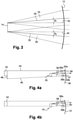
- the picture 3 schematically represents cones of illumination of a projection system according to one embodiment of the invention.
- a first illumination cone 24 has a first indicator 26 as its axis and a second illumination cone 28 has a second indicator 30 as its axis.
- the first indicator 26 is oriented at an angle ⁇ 1 horizontal and the second indicator 30 is oriented at an angle ⁇ 2 horizontal with respect to a direction perpendicular to the screen represented by the straight lines 32, 34 perpendicular to the screen.
- the orientation according to the vertical angle is not shown in this figure.
- the illumination cones 24, 28 are oriented in the same way as the indicators 26, 30, and are thus offset with respect to an illumination cone according to the prior art whose indicators are in the direction perpendicular to the screen.
- the figures 4a and 4b show the effects of this orientation on the illumination of an eyebox and on the optical efficiency of the projection system.
- the figure 4a represents the illumination of an eyebox by a projection system 35 according to the prior art, by means of a semi-reflecting optical element 36.
- An indicator 37 of an illumination cone is represented, and is perpendicular to the screen of the projection system 35.
- the cone of illumination allows the illumination of a zone 38 of the semi-reflecting optical element delimited by the points referenced 40a and 40b.
- a driver of a vehicle equipped with the projection system and the semi-reflecting optical element can see the virtual image displayed by the semi-reflecting optical element from the eye box 42, that is to say a zone in which the driver's eyes are likely to be located, in the context of a normal driving situation.
- the virtual image is visible in a zone delimited by two straight lines, a straight line 44 for upper display and a straight line 46 for lower display.
- the right 44 upper display indicates that the illumination reaches exactly the upper part of the eye box 42
- the lower display line 46 indicates that the illumination reaches the lower part of the eye box 42 as well as an interval 48 additional outside the eye box 42.
- the figure 4b represents the illumination of the eyebox 42 by a projection system 10 according to one embodiment of the invention, by means of a semi-reflecting optical element 12.
- the indicator 50 represented is oriented with respect to a direction perpendicular to the screen 14 of the projection system according to a non-zero horizontal angle.
- the virtual image formed by the semi-reflecting optical element is visible in a zone delimited by two straight lines, a straight line 52 of upper reflection and a straight line 54 of lower reflection.
- the line 52 of upper reflection indicates that the illumination reaches exactly the upper part of the eye box 42
- the line 54 of lower reflection indicates that the illumination reaches exactly the lower part of the eye box 42.
- the projection system 10 allows more suitable lighting of the eyebox 42, by illuminating only the eyebox 42 without loss of lighting, thus improving the optical efficiency, and this thanks to the adjustment of the orientation of the indicators and the opening angle of the cones of illumination coming from the screen. Illuminating only the eyebox 42 also allows the reduction of stray light and the increase of the effective contrast of the virtual image displayed on the semi-reflecting optical element 12.
- the improvement in optical efficiency is also achieved by reducing the angle at the apex of the cone.
- the vertex angle 56 is divided into two angles 56a and 56b between the indicatrix and the cone, called vertex half-angles, of equal values since the indicatrix is the axis of the cone.
- vertex angle 58 is divided into two vertex half-angles 58a and 58b.
- the angle 58 at the top of the cone necessary to cover the entire eye box 42 and made possible by the projection system 10 according to one embodiment of the invention, is less than the angle 56 at the top of the cone obtained by the projection system 35 according to the prior art.
- the cone obtained by the projection system 10 according to a mode of embodiment of the invention is narrower and therefore allows a reduction in the light power to be emitted to obtain the same light power received in the eye box 42.
- the orientation of the indicators is variable depending on the position of the top of the cones and the opening angle of the cone of illumination is preferably constant.
- the improvement in optical efficiency is equal to: 4 ⁇ 1 ⁇ cos 20 ° 4 ⁇ 1 ⁇ cos 15 ° ⁇ 20 ° 15 ° 2 ⁇ 1.77
- the difference in angle between the half-angle 56a, for example, in the system 35 according to the prior art and the corresponding half-angle 58a in the system 10 according to the invention is equal to the angle at which is oriented the indicator 50 of the system 10 with respect to the direction perpendicular to the screen, that is to say the angular difference between the two indicators.
- the improvement in the optical efficiency according to the preceding formula is 1.44, or 40% of additional light power perceived in the eyebox 42.
- one method is to modify the orientation of the light coming from one or more light sources of a backlighting device of the screen 14 of the projection system 10.
- the way in which the light leaves the screen 14 to illuminate the semi-reflecting optical element 12 is determined by the way in which the light coming from the backlighting device enters the screen 14.
- Orientation means indicators allow this orientation in the backlighting device, and these can take several forms, as represented in figures 5a and 5b .
- the figure 5a represents a projection system 10a which is not according to the invention, comprising a backlighting device 59a comprising orientation means composed of an optical system 60a placed between at least one source light, here three light sources 62a, 64a, 66a, and the screen 14.
- the sources 62a, 64a, 66a each emit light, represented here by a single light beam 68a, 70a, 72a for each source, for more than clarity.
- the beams 68a, 70a, 72a are directed towards the screen 14 in a direction perpendicular to the screen.
- the optical system 60a constituting the orientation means allows the orientation of the incident light beams 68a, 70a, 72a on the screen 14, thus allowing the orientation of the indicators 74a, 76a, 78a of the cones of illumination emitted by the screen 14 in the direction of the semi-reflecting optical element 12.
- the optical system 60a is for example composed of a lens 80, 82, 84 per source 62a, 64a, 66a whose axis is offset so as to orient the beams 68a, 70a, 72a according to the desired orientation so as to obtain the desired indicators 74a, 76a, 78a.
- the figure 5b represents a projection system 10b according to the invention comprising a backlighting device 59b comprising orientation means composed of a support 60b of the light sources here three light sources 62b, 64b, 66b, adapted to orient the lighting of each source 62b, 64b, 66b so that the light incident on a point of incidence of the screen 14 is in the direction of the indicatrix desired for the cone of which said point of incidence is the apex.
- the support 60b is curved and the sources 62b, 64b, 66b are placed on this curved support so that the light beams 68b, 70b, 72b emitted by the sources 62b, 64b, 66b are directed along the angle desired for the indicators 74b, 76b, 78b of the cones of illumination emitted from the screen 14.
- the support 60b can be for example spherical, allowing an orientation of the indicators in all directions, or cylindrical , allowing an orientation of the indicators in a limited number of directions, but easier to achieve.
- the orientation means according to the invention can be combined with the optical system 60a of the figure 5a , so that the light is emitted by a plurality of sources placed on the curved support (60b) allowing the orientation of all or part of the emitted light, the light emitted then passing through the optical system (60a) again allowing the orientation of all or part of the light emitted, so that the light incident on a point of incidence of the screen is in the direction desired for the indicator of the cone of which said point of incidence is the vertex.
- the projection system can use different types of screen and backlight technologies, such as Thin Film Transistor (TFT) systems, DLP micro-mirror arrays (for Digital Light Processing in English), laser scanning, micro-mirror LCOS (for Liquid Crystal on Silicon in English), etc.
- TFT Thin Film Transistor
- DLP micro-mirror arrays for Digital Light Processing in English
- laser scanning micro-mirror LCOS (for Liquid Crystal on Silicon in English)
- the orientation means are either one or more optical systems, or a suitable support, or a combination of the two.
Landscapes
- Physics & Mathematics (AREA)
- General Physics & Mathematics (AREA)
- Optics & Photonics (AREA)
- Nonlinear Science (AREA)
- Mathematical Physics (AREA)
- Chemical & Material Sciences (AREA)
- Crystallography & Structural Chemistry (AREA)
- Instrument Panels (AREA)
- Projection Apparatus (AREA)
- Non-Portable Lighting Devices Or Systems Thereof (AREA)
Description
- L'invention concerne les systèmes de projection, notamment pour afficheurs tête haute. En particulier, l'invention concerne un système de projection d'une image virtuelle et un afficheur tête haute destinés à un véhicule automobile.
- Un afficheur tête haute permet la formation d'une image virtuelle grâce à une optique de projection. L'image virtuelle est formée par un système de projection, qui comprend notamment un écran qui forme sur sa surface une image réelle qui est projetée de sorte à former l'image virtuelle visible par l'utilisateur de l'afficheur, se superposant à l'environnement, par exemple la route dans le cas d'une utilisation automobile.
- Dans le cadre de l'utilisation de l'afficheur comme afficheur tête haute dans un véhicule automobile, le conducteur du véhicule, à qui se destinent les informations apparaissant sur l'afficheur tête haute, a une position quasi fixe quand il se trouve sur le siège conducteur pendant la conduite du véhicule. Ainsi, l'image virtuelle est visible uniquement dans une zone appelée boîte à œil, qui représente la zone dans laquelle les yeux du conducteur peuvent se trouver en conditions normales de conduite.
- Pour optimiser les performances énergétiques du système de projection, l'écran émet la lumière avec une forte directivité, afin que l'essentiel de la puissance lumineuse soit émise de façon à être dirigée vers la boîte à œil.
- Les afficheurs existants sont généralement équipés de systèmes de projection émettant de la lumière permettant l'éclairage au minimum de la boite à œil, mais ces systèmes de projection émettent aussi de la lumière dans une zone autour et en dehors de la boîte à œil. Ainsi, la lumière émise en dehors de la boîte à œil n'est pas perçue par le conducteur et la puissance lumineuse dans cette zone est perdue, ce qui diminue le rendement optique du système de projection.
- L'état de la technique antérieur pertinent comprend les documents suivants.
- Le document
US 2014/022645 A1 divulgue un affichage tête haute pour un véhicule dans lequel un rétro-éclairage éclaire un panneau LCD, dont l'image réelle est réfléchie par un pare-brise semiréfléchissant vers une boîte à œil du conducteur. Le système de lentilles du rétro-éclairage est conçu de manière à ce que les cônes de lumière émis par chaque pixel soient efficacement dirigés vers la boîte à œil . - Le document
US 2014/063359 divulgue un affichage tête haute à cristaux liquides pour un véhicule. L'affichage utilise deux systèmes de lentilles pour s'assurer que les cônes de lumière émis par les pixels sont dirigés exactement vers la boîte à œil du conducteur. - Finalement, le document
US 2015/049015 A1 divulgue un affichage tête haute pour un véhicule équipé d'un système de projection ayant écran et rétro-éclairage et d'un élément semi-réfléchissant. - L'invention vise à pallier au moins certains des inconvénients des systèmes de projection connus.
- En particulier, l'invention vise aussi à fournir, dans au moins un mode de réalisation de l'invention, un système de projection permettant un meilleur éclairage de la boite à œil.
- L'invention vise aussi à fournir, dans au moins un mode de réalisation, un système de projection dont le rendement optique est amélioré.
- L'invention vise aussi à fournir, dans au moins un mode de réalisation de l'invention, un système de projection permettant la réduction de la consommation énergétique.
- L'invention vise aussi à fournir, dans au moins un mode de réalisation, un système de projection permettant la réduction de lumière parasite.
- L'invention vise aussi à fournir, dans au moins un mode de réalisation, un système de projection permettant l'augmentation du contraste de l'éclairage.
- Pour ce faire, l'invention concerne un système de projection pour afficheur, notamment afficheur tête haute, selon la revendication 1. Autres modes de réalisation de l'invention sont définis dans les revendications dépendantes.
- Un système de projection selon l'invention permet donc d'adapter la direction des indicatrices des cônes d'éclairement en fonction de la distance de ces cônes avec le cône dont le sommet est le centre de l'écran.
- Pour éclairer la boîte à œil, quelques systèmes de projection de l'art antérieur ont des cônes d'éclairement dont toutes les indicatrices ont la même direction, généralement orthogonale à l'écran. L'invention permet donc d'obtenir des indicatrices orientées dans plusieurs directions différentes, ce qui permet un éclairage plus précis et optimisé de la boîte à œil.
- Avantageusement et selon l'invention, la direction de l'indicatrice de chaque cône est orientée par rapport à une direction perpendiculaire à l'écran, selon un angle θ horizontal défini par θ = θ0 + fh(x-x0) et un angle ψ vertical défini par ψ = ψ0 + fv(y-y0) avec fh une fonction d'orientation horizontale, fv une fonction d'orientation verticale, θ0 l'angle horizontal de la direction de l'indicatrice du cône dont le sommet est le centre de l'écran, ψ0 l'angle vertical de la direction de l'indicatrice du cône dont le sommet est le centre de l'écran, x la coordonnée du sommet de l'indicatrice sur un axe horizontal, x0 la coordonnée du centre de l'écran sur un axe horizontal, y la coordonnée du sommet de l'indicatrice sur un axe vertical et y0 la coordonnée du centre de l'écran sur un axe vertical. Dans ce système de coordonnées, l'axe dit horizontal (x) et l'axe dit vertical (y) se trouvent dans le plan de l'écran 14.
- Selon cet aspect de l'invention, l'orientation de la direction des indicatrices se fait par combinaison de décalages angulaires de la direction de l'indicatrice de chaque cône par rapport à la direction de l'indicatrice dont le cône a comme sommet le centre de l'écran. La fonction d'orientation horizontale et la fonction d'orientation verticale sont des fonctions telles que l'angle de chaque indicatrice de sommet quelconque augmente avec l'augmentation de la distance dudit sommet quelconque avec le centre de l'écran.
- Avantageusement et selon ce dernier aspect de l'invention, la fonction d'orientation horizontale est une fonction nulle et la fonction d'orientation verticale est une fonction linéaire non nulle.
- Autrement dit, θ = θ0 et ψ = ψ0 + av ∗(y-y0) avec av un réel non nul.
- Avantageusement et selon une variante de ce dernier aspect de l'invention, la fonction d'orientation verticale est une fonction nulle et la fonction d'orientation horizontale est une fonction linéaire non nulle.
- Autrement dit, ψ = ψ0 et θ = θ0 + ah ∗(x-x0) avec ah un réel non nul.
- Selon ces aspects de l'invention, la modification de la direction en fonction de l'éloignement des sommets des cônes avec le centre de l'écran s'effectue seulement selon un axe, soit vertical soit horizontal, et ce de façon linéaire.
- Avantageusement et selon une variante de ce dernier aspect de l'invention, la fonction d'orientation horizontale et la fonction d'orientation verticale sont des fonctions linéaires et non nulles.
- Selon cet aspect de l'invention, la modification de la direction en fonction de l'éloignement des sommets des cônes avec le centre de l'écran s'effectue de façon linéaire selon les deux axes, horizontal et vertical.
- Avantageusement et selon l'invention, la fonction d'orientation horizontale et la fonction d'orientation verticale sont des fonctions quadratiques et non nulles.
- Avantageusement et selon l'invention, la fonction d'orientation horizontale et la fonction d'orientation verticale sont des fonctions biquadratiques et non nulles.
- Avantageusement et selon l'invention, les cônes d'éclairement ont un angle au sommet dont la valeur dépend de la distance de chaque sommet de cône avec le centre de l'écran.
- Selon cet aspect de l'invention, le procédé permet d'ajuster la taille des cônes d'éclairement par modification de l'angle au sommet de chaque cône.
- Avantageusement, plus le sommet du cône est éloigné du centre de l'écran, plus la valeur de l'angle au sommet diminue. La réduction des angles au sommet des cônes et donc de la taille des cônes permet d'améliorer le rendement optique du dispositif, en concentrant les rayons lumineux dans une zone plus étroite délimitée par le cône. Cette amélioration du rendement optique est d'autant plus importante dans les zones périphériques d'éclairement, où un cône d'angle au sommet trop élevé entraînerait un éclairage peu précis de l'élément optique semi-réfléchissant et donc de la boîte à œil, en particulier parce qu'une partie de la lumière se propage dans une zone extérieure à la boite à œil et est donc perdue, ce qui réduit le rendement optique. La réduction de l'angle au sommet de chaque cône, plus important dans les zones périphériques c'est-à-dire éloignées du centre de l'écran, permettent donc l'amélioration du rendement optique.
- Avantageusement et selon l'invention, l'indicatrice partant du centre de l'écran a une direction orthogonale à l'écran.
- En d'autres termes, θ0 = ψ0 = 0.
- Selon l'invention, le dispositif de rétro-éclairage comprenant une pluralité de sources lumineuses, les moyens d'orientation comprennent un support courbe des sources lumineuses de sorte à orienter la lumière provenant de chaque source lumineuse de sorte à ce que ladite lumière, incidente sur un point d'incidence de l'écran, soit de même direction que l'indicatrice du cône dont ledit point d'incidence est le sommet.
- Selon l'invention, la modification du support des sources lumineuses permet d'orienter de façon précise la direction de l'éclairement des sources lumineuses en direction de l'écran, afin d'obtenir des directions d'indicatrices précises et éclairer au mieux la boite à œil.
- L'invention concerne également un afficheur tête haute comprenant un système de projection d'image selon l'invention.
- D'autres buts, caractéristiques et avantages de l'invention apparaîtront à la lecture de la description suivante donnée à titre uniquement non limitatif et qui se réfère aux figures annexées dans lesquelles :
- la
figure 1 est une vue schématique d'un système de projection selon un mode de réalisation de l'invention, - la
figure 2 est une vue schématique d'un écran d'un système de projection selon un mode de réalisation de l'invention, - la
figure 3 est une vue schématique d'indicatrices et de cônes d'éclairement d'un système de projection selon un mode de réalisation de l'invention, - la
figure 4a est une vue schématique de l'éclairement de la boite à œil par un élément optique semi-réfléchissant d'un système de projection selon l'art antérieur, - la
figure 4b est une vue schématique de l'éclairement de la boite à œil par un élément optique semi-réfléchissant d'un système de projection selon un mode de réalisation de l'invention, - la
figure 5a représente des moyens d'orientation et un système de projection qui ne sont pas selon l'invention, - la
figure 5b représente des moyens d'orientation et un système de projection selon l'invention. - Les réalisations suivantes sont des exemples. Bien que la description se réfère à un ou plusieurs modes de réalisation, ceci ne signifie pas nécessairement que chaque référence concerne le même mode de réalisation, ou que les caractéristiques s'appliquent seulement à un seul mode de réalisation. De simples caractéristiques de différents modes de réalisation peuvent également être combinées pour fournir d'autres réalisations, à condition que ces modes tombent à l'intérieur de la portée des revendications ci-jointes.
- La
figure 1 représente un système 10 de projection et un élément optique semi-réfléchissant 12, selon un mode de réalisation de l'invention. Le système 10 de projection comprend un écran 14, par exemple un écran à cristaux liquides (ou écran LCD pour Liquid Crystal Display en anglais), permettant l'émission de lumière en direction de l'élément optique semi-réfléchissant 12. Plus précisément, la lumière émise par l'écran 14 sur l'élément optique semi-réfléchissant 12 permet la formation d'une image 16 virtuelle dans le champ de vision d'un utilisateur de l'élément optique semi-réfléchissant 12, par exemple le conducteur d'un véhicule équipé de l'élément optique semi-réfléchissant 12. Pour permettre la formation de l'image virtuelle, l'écran 14 éclaire l'élément optique semi-réfléchissant 12 selon une pluralité de cônes d'éclairement dont les sommets sont des points situés sur l'écran, chaque cône d'éclairement étant notamment défini par son axe, appelé indicatrice du cône. - L'élément optique semi-réfléchissant 12 est une optique de projection susceptible de permettre la formation de l'image 16 virtuelle. Dans le cadre d'une utilisation dans un véhicule automobile, cette optique de projection est par exemple une lame semi-réfléchissante placée entre le conducteur et le pare-brise du véhicule, ou directement le pare-brise du véhicule.
- Le conducteur 18 du véhicule est ici représenté par un des ses yeux. L'objectif de l'écran 14 est de permettre l'éclairage de l'élément optique semi-réfléchissant 12 et ainsi l'affichage de l'image 16 virtuelle de façon à ce qu'elle soit visible par le conducteur 18 dans une zone limitée correspondant aux deux yeux et ajustée pour tenir compte d'éventuels déplacements des yeux qui adviennent dans des conditions normales de conduite. Cette zone dans laquelle l'image 16 virtuelle doit être visible est appelée boite à œil.
- L'objectif de l'invention est d'éclairer au mieux cette boite à œil, pour que l'image 16 virtuelle soit bien visible au conducteur 18 et pour éviter les pertes de rendement optique dues à un éclairage d'une zone trop large dépassant la boite à œil. Le rendement optique est le rapport entre la puissance lumineuse de l'éclairage reçue sur la puissance lumineuse de l'éclairage émise.
- La
figure 2 représente une partie d'un écran 14 d'un système de projection selon un mode de réalisation de l'invention, ainsi qu'une indicatrice 20 d'un cône d'éclairement qui part d'un sommet 22 situé sur l'écran 14 et est dirigée vers l'élément optique semi-réfléchissant 12 sur lafigure 1 , non représenté sur cette figure. - Une droite d perpendiculaire à l'écran 14 et passant par le sommet 22 représente une indicatrice classique d'un système de projection selon l'art antérieur. Un système selon un mode de réalisation de l'invention permet l'orientation d'une indicatrice 20 selon une direction différente de l'indicatrice classique, l'orientation de l'indicatrice par rapport à cette droite d étant représentée par la combinaison de deux angles, un angle θ dit horizontal, qui représente l'orientation de l'indicatrice 20 par rapport à la droite d selon une première direction dx d'un repère orthonormé, direction dite par la suite direction horizontale et un angle ψ dit vertical qui représente l'orientation de l'indicatrice 20 par rapport à la droite d selon une seconde direction dy dudit repère orthonormé, direction dite par la suite direction verticale. La valeur de chaque angle θ, ψ est calculée selon l'invention en fonction de l'éloignement du sommet 22 du cône avec le point situé au centre de l'écran 14 (non représenté sur cette figure). L'angle θ horizontal est défini par la formule θ = θ0 + fh(x-x0), avec fh une fonction d'orientation horizontale, θ0 l'angle horizontal de la direction de l'indicatrice du cône dont le sommet est le centre de l'écran 14, x la coordonnée du sommet 22 de l'indicatrice 20 sur un axe horizontal et x0 la coordonnée du centre de l'écran 14 sur un axe horizontal. L'angle ψ vertical est défini par la formule ψ = ψ0 + fv(y-y0), avec fv une fonction d'orientation verticale, ψ0 l'angle vertical de la direction de l'indicatrice du cône dont le sommet est le centre de l'écran, y la coordonnée du sommet 22 de l'indicatrice 20 sur un axe vertical, et y0 la coordonnée du centre de l'écran 14 sur un axe vertical.
- La fonction fh d'orientation horizontale et la fonction fv d'orientation verticale sont déterminées en fonction de différents paramètres, par exemple la position de la boite à œil et la dimension de la boite à œil, la position de l'élément semi-réfléchissant, la courbure de l'élément semi-réfléchissant, la distance entre l'élément réfléchissant et l'écran, etc.
- Elles peuvent être des fonctions de différent types, par exemple :
- la fonction fh d'orientation horizontale est linéaire non nulle et la fonction fv d'orientation verticale est nulle,
- la fonction fv d'orientation verticale est linéaire non nulle et la fonction fh d'orientation horizontale est nulle,
- la fonction fh d'orientation horizontale et la fonction fv d'orientation verticale sont des fonctions linéaires et non nulles,
- la fonction fh d'orientation horizontale et la fonction fv d'orientation verticale sont des fonctions quadratiques et non nulles,
- la fonction fh d'orientation horizontale et la fonction fv d'orientation verticale sont des fonctions biquadratiques et non nulles.
- Les deux premiers exemples sont chacun une variation linéaire sur un seul axe (horizontal ou vertical). Le troisième exemple est une variation bilinéaire, sur deux axes.
- Les modes de réalisations décrits par la suite utilisent une variation bilinéaire, qui est celle qui donne les meilleurs résultats, en permettant une variation progressive et linéaire de l'orientation de chaque indicatrice en fonction de sa distance avec le centre de l'écran 14. Pour des raisons de clarté, les
figures 3, 4a, 4b ,5 et 6 représentent le système de projection uniquement selon l'axe horizontal, et l'orientation des indicatrices est visible selon l'angle θ horizontal. Toutes les caractéristiques décrites en références auxfigures 3, 4a, 4b ,5 et 6 s'appliquent aussi à l'orientation des indicatrices selon l'angle ψ vertical. - La
figure 3 représente schématiquement des cônes d'éclairement d'un système de projection selon un mode de réalisation de l'invention. - Seul l'écran 14 du système de projection est représenté, ledit écran 14 permettant l'éclairage de l'élément optique semi-réfléchissant 12. L'écran 14 émet de la lumière vers l'élément optique semi-réfléchissant 12 selon des cônes d'éclairement, dont deux sont représentés sur cette figure : un premier cône 24 d'éclairement a comme axe une première indicatrice 26 et un deuxième cône 28 d'éclairement a comme axe une deuxième indicatrice 30. La première indicatrice 26 est orientée selon un angle θ1 horizontal et la deuxième indicatrice 30 est orientée selon un angle θ2 horizontal par rapport à une direction perpendiculaire à l'écran représentée par les droites 32, 34 perpendiculaires à l'écran. Comme expliqué précédemment, l'orientation selon l'angle vertical n'est pas représentée sur cette figure. Les cônes 24, 28 d'éclairement sont orientés de la même façon que les indicatrices 26, 30, et sont ainsi décalés par rapport à un cône d'éclairement selon l'art antérieur dont les indicatrices sont de direction perpendiculaire à l'écran.
- Les
figures 4a et 4b montrent les effets de cette orientation sur l'éclairage d'une boite à œil et sur le rendement optique du système de projection. - La
figure 4a représente l'éclairement d'une boite à œil par un système 35 de projection selon l'art antérieur, par le biais d'un élément optique semi-réfléchissant 36. Une indicatrice 37 d'un cône d'éclairement est représentée, et est perpendiculaire à l'écran du système de projection 35. Le cône d'éclairement permet l'éclairement d'une zone 38 de l'élément optique semi-réfléchissant délimitée par les points référencés 40a et 40b. Un conducteur d'un véhicule équipé du système de projection et de l'élément optique semi-réfléchissant peut voir l'image virtuelle affichée par l'élément optique semi-réfléchissant depuis la boite à œil 42, c'est-à-dire une zone dans laquelle les yeux du conducteur sont susceptibles de se situer, dans le cadre d'une situation normale de conduite. L'image virtuelle est visible dans une zone délimitée par deux droites, une droite 44 d'affichage supérieure et une droite 46 d'affichage inférieure. La droite 44 d'affichage supérieure indique que l'éclairement atteint exactement la partie supérieure de la boite à œil 42, et la droite 46 d'affichage inférieure indique que l'éclairement atteint la partie inférieure de la boite à œil 42 ainsi qu'un intervalle 48 supplémentaire extérieur à la boite à œil 42. - La
figure 4b représente l'éclairement de la boite à œil 42 par un système 10 de projection selon un mode de réalisation de l'invention, par le biais d'un élément optique semi-réfléchissant 12. Contrairement au système 35 de projection selon l'art antérieur décrit en référence à lafigure 4a , l'indicatrice 50 représentée est orientée par rapport à une direction perpendiculaire à l'écran 14 du système de projection selon un angle horizontal non nul. L'image virtuelle formée par l'élément optique semi-réfléchissant est visible dans une zone délimitée par deux droites, une droite 52 de réflexion supérieure et une droite 54 de réflexion inférieure. La droite 52 de réflexion supérieure indique que l'éclairement atteint exactement la partie supérieure de la boite à œil 42, et la droite 54 de réflexion inférieure indique que l'éclairement atteint exactement la partie inférieure de la boite à œil 42. Contrairement au système 35 de projection selon l'art antérieur représentéfigure 4a , le système 10 de projection selon ce mode de réalisation permet un éclairage plus adapté de la boite à œil 42, en éclairant seulement la boite à œil 42 sans pertes d'éclairage, améliorant ainsi le rendement optique, et ce grâce au réglage de l'orientation des indicatrices et de l'angle d'ouverture des cônes d'éclairement provenant de l'écran. Éclairer uniquement la boite à œil 42 permet en outre la réduction de la lumière parasite et l'augmentation du contraste effectif de l'image virtuelle affichée sur l'élément optique semi-réfléchissant 12. - En outre l'amélioration du rendement optique se fait aussi grâce à la réduction de l'angle au sommet du cône. Sur la
figure 4a , l'angle 56 au sommet est divisé en deux angles 56a et 56b entre l'indicatrice et le cône, appelés demi-angles au sommet, de valeurs égales puisque l'indicatrice est l'axe du cône. De la même façon, sur lafigure 4b , l'angle 58 au sommet est divisé en deux demi-angles au sommet 58a et 58b. L'angle 58 au sommet du cône nécessaire pour couvrir l'intégralité de la boite à œil 42 et rendu possible par le système 10 de projection selon un mode de réalisation de l'invention, est inférieur à l'angle 56 au sommet du cône obtenu par le système 35 de projection selon l'art antérieur. Ainsi, le cône obtenu par le système 10 de projection selon un mode de réalisation de l'invention est plus étroit et donc permet une réduction de la puissance lumineuse à émettre pour obtenir une même puissance lumineuse reçue dans la boite à œil 42. Avantageusement, l'orientation des indicatrices est variable en fonction de la position du sommet des cônes et l'angle d'ouverture du cône d'éclairement est constant de préférence. - En pratique, si la valeur des demi-angles 56a, 56b au sommet du cône obtenus par le système de projection selon l'art antérieur est égale à 20° et si la valeur des demi-angles 58a, 58b au sommet du cône obtenus par le système de projection selon un mode de réalisation de l'invention est égale à 15°, l'amélioration du rendement optique est égal à :

- En général, la différence d'angle entre le demi-angle 56a, par exemple, dans le système 35 selon l'art antérieur et le demi-angle 58a correspondant dans le système 10 selon l'invention est égale à l'angle selon lequel est orienté l'indicatrice 50 du système 10 par rapport à la direction perpendiculaire à l'écran, c'est-à-dire la différence angulaire entre les deux indicatrices. Dans le cas présenté ci-dessus, l'indicatrice est orientée de 20-15=5° par rapport à la direction perpendiculaire à l'écran. Pour une orientation de 3°, l'amélioration du rendement optique selon la formule précédente est de 1,44, soit 40% de puissance lumineuse perçue supplémentaire dans la boite à œil 42.
- Pour permettre l'orientation des indicatrices de chaque cône d'éclairement de l'écran, une méthode est de modifier l'orientation de la lumière provenant d'une ou de plusieurs sources lumineuses d'un dispositif de rétro-éclairage de l'écran 14 du système 10 de projection. Ainsi, la façon dont la lumière sort de l'écran 14 pour éclairer l'élément optique semi-réfléchissant 12 est déterminée par la façon dont la lumière provenant du dispositif de rétro-éclairage entre dans l'écran 14. Des moyens d'orientation des indicatrices permettent cette orientation dans le dispositif de rétro-éclairage, et ceux-ci peuvent prendre plusieurs formes, comme représentées aux
figures 5a et 5b . - La
figure 5a représente un système 10a de projection qui n'est pas selon l'invention, comprenant un dispositif 59a de rétro-éclairage comprenant des moyens d'orientation composés d'un système 60a optique placé entre au moins une source lumineuse, ici trois sources lumineuses 62a, 64a, 66a, et l'écran 14. Les sources 62a, 64a, 66a émettent chacune de la lumière, représentée ici par un faisceau 68a, 70a, 72a lumineux unique pour chaque source, pour plus de clarté. À la sortie des sources lumineuses, les faisceaux 68a, 70a, 72a sont dirigés vers l'écran 14 selon une direction perpendiculaire à l'écran. Le système 60a optique constituant les moyens d'orientation permet l'orientation des faisceaux 68a, 70a, 72a lumineux incidents sur l'écran 14, permettant ainsi l'orientation des indicatrices 74a, 76a, 78a des cônes d'éclairement émis par l'écran 14 en direction de l'élément optique semi-réfléchissant 12. L'indicatrice 76a au centre de l'écran 14 est ici perpendiculaire à l'écran, c'est-à-dire que θ0=ψ0=0. - Le système 60a optique est par exemple composé d'une lentille 80, 82, 84 par source 62a, 64a, 66a dont l'axe est décalé de façon à orienter les faisceaux 68a, 70a, 72a selon l'orientation souhaitée de façon à obtenir les indicatrices 74a, 76a, 78a souhaitées.
- La
figure 5b représente un système 10b de projection selon l'invention comprenant un dispositif 59b de rétro-éclairage comprenant des moyens d'orientation composés d'un support 60b des sources lumineuses ici trois sources lumineuses 62b, 64b, 66b, adapté pour orienter l'éclairage de chaque source 62b, 64b, 66b de sorte à ce que la lumière incidente sur un point d'incidence de l'écran 14 soit dans la direction de l'indicatrice souhaitée pour le cône dont ledit point d'incidence est le sommet. En l'occurrence, le support 60b est courbe et les sources 62b, 64b, 66b sont placées sur ce support courbe de façon à ce que les faisceaux 68b, 70b, 72b lumineux émis par les sources 62b, 64b, 66b soient dirigés selon l'angle souhaité pour les indicatrices 74b, 76b, 78b des cônes d'éclairement émis depuis l'écran 14. Selon les modes de réalisations, le support 60b peut être par exemple sphérique, permettant une orientation des indicatrices dans toutes les directions, ou cylindrique, permettant une orientation des indicatrices dans un nombre de directions limité, mais plus simple à réaliser. - L'invention ne se limite pas aux seuls modes de réalisation décrits. En particulier, les moyens d'orientation selon l'invention peut être combiné avec le système 60a optique de la
figure 5a , de sorte à ce que la lumière soit émise par une pluralité de sources placées sur le support (60b) courbe permettant l'orientation de tout ou partie de la lumière émise, la lumière émise traversant ensuite le système (60a) optique permettant à nouveau l'orientation de tout ou partie de la lumière émise, de sorte à ce que la lumière incidente sur un point d'incidence de l'écran soit dans la direction souhaitée pour l'indicatrice du cône dont ledit point d'incidence est le sommet. - De plus, le système de projection peut utiliser différents types de technologies d'écran et de rétro-éclairage, comme par exemple les systèmes de type transistor en couches minces (en anglais Thin Film Transistor ou TFT), matrice de micro-miroirs DLP (pour Digital Light Processing en anglais), balayage laser, micro-miroir LCOS (pour Liquid Crystal on Silicon en anglais), etc. Selon les technologies utilisées, les moyens d'orientation sont soit un ou plusieurs systèmes optiques, soit un support adapté, soit une combinaison des deux.
Claims (11)
- Système de projection pour afficheur, notamment afficheur tête haute destiné à un véhicule automobile, d'une image virtuelle visible uniquement dans une zone appelée boîte à œil (42) comprenant :- un élément optique semi-réfléchissant (12),- un dispositif (59b) de rétro-éclairage,- un écran (14), adapté pour être éclairé par ledit dispositif ( 59b) de rétro-éclairage et adapté pour éclairer l'élément optique semi-réfléchissant (12) selon des cônes (24, 28) d'éclairement, chaque cône (24, 28) d'éclairement ayant un axe, dit indicatrice (20, 26, 30, 50), partant d'un point (22), dit sommet du cône, situé sur l'écran (14) et dirigé vers l'élément optique semi-réfléchissant (12), ledit système de projection comprenant des moyens (60b) d'orientation des directions des indicatrices (20, 26, 30, 50) des cônes (24, 28), lesdits moyens d'orientation étant adaptés pour orienter les indicatrices (20, 26, 30, 50) selon une direction calculée par une fonction d'orientation dépendant de la distance de chaque sommet (22) de cône avec le centre de l'écran (14), le dispositif (59b) de rétro-éclairage comprenant des sources (62b, 64b, 66b) llumineuses ledit système de projection étant caractérisé en ce que les moyens d'orientation comprennent un support (60b) des sources (62b, 64b, 66b) lumineuses adapté pour orienter la lumière provenant de chaque source lumineuse de sorte à ce que ladite lumière, incidente sur un point d'incidence de l'écran (14), soit dans la direction de l'indicatrice du cône dont ledit point d'incidence est le sommet de sorte à éclairer la boîte à œil (42) sans pertes d'éclairage.
- Système de projection selon la revendication 1, dans lequel la direction de l'indicatrice de chaque cône (24, 28) est orientée par rapport à une direction perpendiculaire à l'écran (14), selon un angle θ dit horizontal défini par θ = θ0 + fh(x-x0) et un angle ψ dit vertical défini par ψ = ψ0 + fv(y-y0) avec fh une fonction d'orientation horizontale, fv une fonction d'orientation verticale, θ0 l'angle horizontal de la direction de l'indicatrice du cône dont le sommet est le centre de l'écran (14), ψ0 l'angle vertical de la direction de l'indicatrice du cône dont le sommet est le centre de l'écran (14), x la coordonnée du sommet (22) de l'indicatrice sur un premier axe qui est dit horizontal, x0 la coordonnée du centre de l'écran (14) sur le premier axe, y la coordonnée du sommet (22) de l'indicatrice sur un second axe qui est dit vertical, et y0 la coordonnée du centre de l'écran (14)sur le second axe, le premier axe et le second axe se trouvant dans le plan de l'écran (14).
- Système de projection selon la revendication 2, dans lequel la fonction d'orientation horizontale est une fonction nulle et la fonction d'orientation verticale est une fonction linéaire non nulle.
- Système de projection selon la revendication 2, dans lequel la fonction d'orientation verticale est une fonction nulle et la fonction d'orientation horizontale est une fonction linéaire non nulle.
- Système de projection selon la revendication 2, dans lequel la fonction d'orientation horizontale et la fonction d'orientation verticale sont des fonctions linéaires et non nulles.
- Système de projection selon la revendication 2, dans lequel l'une au moins des fonctions d'orientation horizontale et fonction d'orientation verticale est une fonction quadratique non nulle.
- Système de projection selon la revendication 2, dans lequel l'une au moins des fonctions d'orientation horizontale et fonction d'orientation verticale est une fonction biquadratique non nulle.
- Système de projection selon l'une des revendications 1 à 7, dans lequel les cônes (24, 28) d'éclairement ont un angle (58) au sommet dont la valeur est fonction de la distance de chaque sommet (22) de cône avec le centre de l'écran (14).
- Système de projection selon la revendication 8, dans lequel plus le sommet du cône est éloigné du centre de l'écran, plus la valeur de l'angle au sommet diminue.
- Système de projection selon l'une des revendications 1 à 9, dans lequel l'indicatrice partant du centre de l'écran (14) a une direction orthogonale à l'écran (14).
- Afficheur tête haute qui comprend un système de projection d'image selon l'une des revendications 1 à 10.
Applications Claiming Priority (2)
| Application Number | Priority Date | Filing Date | Title |
|---|---|---|---|
| FR1557151A FR3039664B1 (fr) | 2015-07-27 | 2015-07-27 | Systeme de projection pour afficheur et afficheur tete haute associe |
| PCT/EP2016/067960 WO2017017160A1 (fr) | 2015-07-27 | 2016-07-27 | Système de projection d'un afficheur tête haute |
Publications (2)
| Publication Number | Publication Date |
|---|---|
| EP3329319A1 EP3329319A1 (fr) | 2018-06-06 |
| EP3329319B1 true EP3329319B1 (fr) | 2022-01-19 |
Family
ID=56741008
Family Applications (1)
| Application Number | Title | Priority Date | Filing Date |
|---|---|---|---|
| EP16754203.4A Active EP3329319B1 (fr) | 2015-07-27 | 2016-07-27 | Système de projection d'un afficheur tête haute |
Country Status (3)
| Country | Link |
|---|---|
| EP (1) | EP3329319B1 (fr) |
| FR (1) | FR3039664B1 (fr) |
| WO (1) | WO2017017160A1 (fr) |
Families Citing this family (2)
| Publication number | Priority date | Publication date | Assignee | Title |
|---|---|---|---|---|
| FR3072785B1 (fr) * | 2017-10-24 | 2019-11-01 | Valeo Comfort And Driving Assistance | Afficheur tete haute |
| DE102019203500A1 (de) * | 2019-03-14 | 2020-09-17 | Volkswagen Aktiengesellschaft | Verfahren zur Beeinflussung von Lichtstrahlen im Innenraum eines Kraftfahrzeugs sowie Kraftfahrzeug zur Durchführung des Verfahrens und Spiegelbank für ein solches Kraftfahrzeug |
Family Cites Families (3)
| Publication number | Priority date | Publication date | Assignee | Title |
|---|---|---|---|---|
| JP5674032B2 (ja) * | 2011-03-25 | 2015-02-18 | 日本精機株式会社 | ヘッドアップディスプレイ装置 |
| FR2980856A1 (fr) * | 2011-10-01 | 2013-04-05 | Johnson Contr Automotive Elect | Dispositif d'affichage, notamment pour vehicule automobile |
| TWI459356B (zh) * | 2012-08-31 | 2014-11-01 | Nat Univ Tsing Hua | 區塊動態驅動之背光模組及其抬頭顯示裝置 |
-
2015
- 2015-07-27 FR FR1557151A patent/FR3039664B1/fr active Active
-
2016
- 2016-07-27 WO PCT/EP2016/067960 patent/WO2017017160A1/fr active Application Filing
- 2016-07-27 EP EP16754203.4A patent/EP3329319B1/fr active Active
Non-Patent Citations (1)
| Title |
|---|
| None * |
Also Published As
| Publication number | Publication date |
|---|---|
| WO2017017160A1 (fr) | 2017-02-02 |
| FR3039664B1 (fr) | 2019-09-13 |
| FR3039664A1 (fr) | 2017-02-03 |
| EP3329319A1 (fr) | 2018-06-06 |
Similar Documents
| Publication | Publication Date | Title |
|---|---|---|
| EP3213951B1 (fr) | Dispositif d'eclairage pour vehicule avec presentation d'information d'aide a la conduite | |
| EP2875398B1 (fr) | Dispositif et procede d'emission d'un faisceau lumineux destine a former une image, systeme de projection et afficheur utilisant ledit dispositif | |
| EP0737870A1 (fr) | Système de projection comportant un réflecteur et une lentille de champ à surface libre | |
| FR2993677A1 (fr) | Dispositif et procede d'emission d'un faisceau lumineux destine a former une image, systeme de projection et afficheur utilisant ledit dispositif | |
| FR2959022A1 (fr) | Dispositif de visualisation a "combineur" optique corrige des aberrations chromatiques | |
| EP1702225A1 (fr) | Lentille de fresnel et dispositif d affichage a projection u tilisant une telle lentille | |
| FR2986624A1 (fr) | Projecteur optique a ecran de projection semi-transparent | |
| EP3329319B1 (fr) | Système de projection d'un afficheur tête haute | |
| WO2016087803A1 (fr) | Afficheur tête haute à fenêtre de vue ajustable | |
| EP3084521B1 (fr) | Système et procédé de projection d'image et afficheur utilisant ledit système | |
| WO2007036550A1 (fr) | Dispositif optique de superposition d'images electroniques devant un objectif | |
| EP3201519B1 (fr) | Systeme d'eclairage a profil d'intensite optimise pour projecteur de vehicule automobile | |
| WO2017017162A1 (fr) | Afficheur tête-haute compact | |
| FR3002802A1 (fr) | Dispositif d'affichage tete haute avec diffuseur comportant un miroir | |
| FR3018929A1 (fr) | Dispositif de visualisation comprenant un combineur a taux de reflexion variable | |
| FR3039665B1 (fr) | Systeme de projection pour afficheur et afficheur tete haute | |
| FR2992071A1 (fr) | Dispositif d'affichage tete haute panoramique | |
| FR2858068A1 (fr) | Systeme de projection d'images pour viseur tete haute | |
| EP3396444B1 (fr) | Dispositif de production d'un faisceau lumineux polarisé, dispositif de génération d'image et afficheur tête haute | |
| EP3227744B1 (fr) | Afficheur tête-haute à générateur latéral | |
| FR3059642A1 (fr) | Masque de plongee avec affichage. | |
| FR3094098A1 (fr) | Afficheur tête haute avec écran courbe | |
| EP3017333B1 (fr) | Viseur tete-haute | |
| FR3072474A1 (fr) | Dispositif de generation d'images et afficheur tete haute comprenant un tel dispositif | |
| FR3000231A1 (fr) | Systeme et procede d'affichage d'informations pour vehicules automobile |
Legal Events
| Date | Code | Title | Description |
|---|---|---|---|
| STAA | Information on the status of an ep patent application or granted ep patent |
Free format text: STATUS: UNKNOWN |
|
| STAA | Information on the status of an ep patent application or granted ep patent |
Free format text: STATUS: THE INTERNATIONAL PUBLICATION HAS BEEN MADE |
|
| PUAI | Public reference made under article 153(3) epc to a published international application that has entered the european phase |
Free format text: ORIGINAL CODE: 0009012 |
|
| STAA | Information on the status of an ep patent application or granted ep patent |
Free format text: STATUS: REQUEST FOR EXAMINATION WAS MADE |
|
| 17P | Request for examination filed |
Effective date: 20180129 |
|
| AK | Designated contracting states |
Kind code of ref document: A1 Designated state(s): AL AT BE BG CH CY CZ DE DK EE ES FI FR GB GR HR HU IE IS IT LI LT LU LV MC MK MT NL NO PL PT RO RS SE SI SK SM TR |
|
| AX | Request for extension of the european patent |
Extension state: BA ME |
|
| DAV | Request for validation of the european patent (deleted) | ||
| DAX | Request for extension of the european patent (deleted) | ||
| STAA | Information on the status of an ep patent application or granted ep patent |
Free format text: STATUS: EXAMINATION IS IN PROGRESS |
|
| 17Q | First examination report despatched |
Effective date: 20190204 |
|
| STAA | Information on the status of an ep patent application or granted ep patent |
Free format text: STATUS: EXAMINATION IS IN PROGRESS |
|
| GRAP | Despatch of communication of intention to grant a patent |
Free format text: ORIGINAL CODE: EPIDOSNIGR1 |
|
| STAA | Information on the status of an ep patent application or granted ep patent |
Free format text: STATUS: GRANT OF PATENT IS INTENDED |
|
| INTG | Intention to grant announced |
Effective date: 20210223 |
|
| GRAJ | Information related to disapproval of communication of intention to grant by the applicant or resumption of examination proceedings by the epo deleted |
Free format text: ORIGINAL CODE: EPIDOSDIGR1 |
|
| STAA | Information on the status of an ep patent application or granted ep patent |
Free format text: STATUS: EXAMINATION IS IN PROGRESS |
|
| INTC | Intention to grant announced (deleted) | ||
| GRAP | Despatch of communication of intention to grant a patent |
Free format text: ORIGINAL CODE: EPIDOSNIGR1 |
|
| STAA | Information on the status of an ep patent application or granted ep patent |
Free format text: STATUS: GRANT OF PATENT IS INTENDED |
|
| INTG | Intention to grant announced |
Effective date: 20210823 |
|
| GRAS | Grant fee paid |
Free format text: ORIGINAL CODE: EPIDOSNIGR3 |
|
| GRAA | (expected) grant |
Free format text: ORIGINAL CODE: 0009210 |
|
| STAA | Information on the status of an ep patent application or granted ep patent |
Free format text: STATUS: THE PATENT HAS BEEN GRANTED |
|
| AK | Designated contracting states |
Kind code of ref document: B1 Designated state(s): AL AT BE BG CH CY CZ DE DK EE ES FI FR GB GR HR HU IE IS IT LI LT LU LV MC MK MT NL NO PL PT RO RS SE SI SK SM TR |
|
| REG | Reference to a national code |
Ref country code: GB Ref legal event code: FG4D Free format text: NOT ENGLISH |
|
| REG | Reference to a national code |
Ref country code: CH Ref legal event code: EP |
|
| REG | Reference to a national code |
Ref country code: DE Ref legal event code: R096 Ref document number: 602016068477 Country of ref document: DE |
|
| REG | Reference to a national code |
Ref country code: AT Ref legal event code: REF Ref document number: 1464133 Country of ref document: AT Kind code of ref document: T Effective date: 20220215 |
|
| REG | Reference to a national code |
Ref country code: IE Ref legal event code: FG4D Free format text: LANGUAGE OF EP DOCUMENT: FRENCH |
|
| REG | Reference to a national code |
Ref country code: LT Ref legal event code: MG9D |
|
| REG | Reference to a national code |
Ref country code: NL Ref legal event code: MP Effective date: 20220119 |
|
| REG | Reference to a national code |
Ref country code: AT Ref legal event code: MK05 Ref document number: 1464133 Country of ref document: AT Kind code of ref document: T Effective date: 20220119 |
|
| PG25 | Lapsed in a contracting state [announced via postgrant information from national office to epo] |
Ref country code: NL Free format text: LAPSE BECAUSE OF FAILURE TO SUBMIT A TRANSLATION OF THE DESCRIPTION OR TO PAY THE FEE WITHIN THE PRESCRIBED TIME-LIMIT Effective date: 20220119 |
|
| PG25 | Lapsed in a contracting state [announced via postgrant information from national office to epo] |
Ref country code: SE Free format text: LAPSE BECAUSE OF FAILURE TO SUBMIT A TRANSLATION OF THE DESCRIPTION OR TO PAY THE FEE WITHIN THE PRESCRIBED TIME-LIMIT Effective date: 20220119 Ref country code: RS Free format text: LAPSE BECAUSE OF FAILURE TO SUBMIT A TRANSLATION OF THE DESCRIPTION OR TO PAY THE FEE WITHIN THE PRESCRIBED TIME-LIMIT Effective date: 20220119 Ref country code: PT Free format text: LAPSE BECAUSE OF FAILURE TO SUBMIT A TRANSLATION OF THE DESCRIPTION OR TO PAY THE FEE WITHIN THE PRESCRIBED TIME-LIMIT Effective date: 20220519 Ref country code: NO Free format text: LAPSE BECAUSE OF FAILURE TO SUBMIT A TRANSLATION OF THE DESCRIPTION OR TO PAY THE FEE WITHIN THE PRESCRIBED TIME-LIMIT Effective date: 20220419 Ref country code: LT Free format text: LAPSE BECAUSE OF FAILURE TO SUBMIT A TRANSLATION OF THE DESCRIPTION OR TO PAY THE FEE WITHIN THE PRESCRIBED TIME-LIMIT Effective date: 20220119 Ref country code: HR Free format text: LAPSE BECAUSE OF FAILURE TO SUBMIT A TRANSLATION OF THE DESCRIPTION OR TO PAY THE FEE WITHIN THE PRESCRIBED TIME-LIMIT Effective date: 20220119 Ref country code: ES Free format text: LAPSE BECAUSE OF FAILURE TO SUBMIT A TRANSLATION OF THE DESCRIPTION OR TO PAY THE FEE WITHIN THE PRESCRIBED TIME-LIMIT Effective date: 20220119 Ref country code: BG Free format text: LAPSE BECAUSE OF FAILURE TO SUBMIT A TRANSLATION OF THE DESCRIPTION OR TO PAY THE FEE WITHIN THE PRESCRIBED TIME-LIMIT Effective date: 20220419 |
|
| PG25 | Lapsed in a contracting state [announced via postgrant information from national office to epo] |
Ref country code: PL Free format text: LAPSE BECAUSE OF FAILURE TO SUBMIT A TRANSLATION OF THE DESCRIPTION OR TO PAY THE FEE WITHIN THE PRESCRIBED TIME-LIMIT Effective date: 20220119 Ref country code: LV Free format text: LAPSE BECAUSE OF FAILURE TO SUBMIT A TRANSLATION OF THE DESCRIPTION OR TO PAY THE FEE WITHIN THE PRESCRIBED TIME-LIMIT Effective date: 20220119 Ref country code: GR Free format text: LAPSE BECAUSE OF FAILURE TO SUBMIT A TRANSLATION OF THE DESCRIPTION OR TO PAY THE FEE WITHIN THE PRESCRIBED TIME-LIMIT Effective date: 20220420 Ref country code: FI Free format text: LAPSE BECAUSE OF FAILURE TO SUBMIT A TRANSLATION OF THE DESCRIPTION OR TO PAY THE FEE WITHIN THE PRESCRIBED TIME-LIMIT Effective date: 20220119 Ref country code: AT Free format text: LAPSE BECAUSE OF FAILURE TO SUBMIT A TRANSLATION OF THE DESCRIPTION OR TO PAY THE FEE WITHIN THE PRESCRIBED TIME-LIMIT Effective date: 20220119 |
|
| PG25 | Lapsed in a contracting state [announced via postgrant information from national office to epo] |
Ref country code: IS Free format text: LAPSE BECAUSE OF FAILURE TO SUBMIT A TRANSLATION OF THE DESCRIPTION OR TO PAY THE FEE WITHIN THE PRESCRIBED TIME-LIMIT Effective date: 20220519 |
|
| REG | Reference to a national code |
Ref country code: DE Ref legal event code: R097 Ref document number: 602016068477 Country of ref document: DE |
|
| PG25 | Lapsed in a contracting state [announced via postgrant information from national office to epo] |
Ref country code: SM Free format text: LAPSE BECAUSE OF FAILURE TO SUBMIT A TRANSLATION OF THE DESCRIPTION OR TO PAY THE FEE WITHIN THE PRESCRIBED TIME-LIMIT Effective date: 20220119 Ref country code: SK Free format text: LAPSE BECAUSE OF FAILURE TO SUBMIT A TRANSLATION OF THE DESCRIPTION OR TO PAY THE FEE WITHIN THE PRESCRIBED TIME-LIMIT Effective date: 20220119 Ref country code: RO Free format text: LAPSE BECAUSE OF FAILURE TO SUBMIT A TRANSLATION OF THE DESCRIPTION OR TO PAY THE FEE WITHIN THE PRESCRIBED TIME-LIMIT Effective date: 20220119 Ref country code: EE Free format text: LAPSE BECAUSE OF FAILURE TO SUBMIT A TRANSLATION OF THE DESCRIPTION OR TO PAY THE FEE WITHIN THE PRESCRIBED TIME-LIMIT Effective date: 20220119 Ref country code: DK Free format text: LAPSE BECAUSE OF FAILURE TO SUBMIT A TRANSLATION OF THE DESCRIPTION OR TO PAY THE FEE WITHIN THE PRESCRIBED TIME-LIMIT Effective date: 20220119 Ref country code: CZ Free format text: LAPSE BECAUSE OF FAILURE TO SUBMIT A TRANSLATION OF THE DESCRIPTION OR TO PAY THE FEE WITHIN THE PRESCRIBED TIME-LIMIT Effective date: 20220119 |
|
| PLBE | No opposition filed within time limit |
Free format text: ORIGINAL CODE: 0009261 |
|
| STAA | Information on the status of an ep patent application or granted ep patent |
Free format text: STATUS: NO OPPOSITION FILED WITHIN TIME LIMIT |
|
| PG25 | Lapsed in a contracting state [announced via postgrant information from national office to epo] |
Ref country code: AL Free format text: LAPSE BECAUSE OF FAILURE TO SUBMIT A TRANSLATION OF THE DESCRIPTION OR TO PAY THE FEE WITHIN THE PRESCRIBED TIME-LIMIT Effective date: 20220119 |
|
| 26N | No opposition filed |
Effective date: 20221020 |
|
| PG25 | Lapsed in a contracting state [announced via postgrant information from national office to epo] |
Ref country code: SI Free format text: LAPSE BECAUSE OF FAILURE TO SUBMIT A TRANSLATION OF THE DESCRIPTION OR TO PAY THE FEE WITHIN THE PRESCRIBED TIME-LIMIT Effective date: 20220119 Ref country code: MC Free format text: LAPSE BECAUSE OF FAILURE TO SUBMIT A TRANSLATION OF THE DESCRIPTION OR TO PAY THE FEE WITHIN THE PRESCRIBED TIME-LIMIT Effective date: 20220119 |
|
| REG | Reference to a national code |
Ref country code: CH Ref legal event code: PL |
|
| GBPC | Gb: european patent ceased through non-payment of renewal fee |
Effective date: 20220727 |
|
| REG | Reference to a national code |
Ref country code: BE Ref legal event code: MM Effective date: 20220731 |
|
| PG25 | Lapsed in a contracting state [announced via postgrant information from national office to epo] |
Ref country code: LU Free format text: LAPSE BECAUSE OF NON-PAYMENT OF DUE FEES Effective date: 20220727 Ref country code: LI Free format text: LAPSE BECAUSE OF NON-PAYMENT OF DUE FEES Effective date: 20220731 Ref country code: CH Free format text: LAPSE BECAUSE OF NON-PAYMENT OF DUE FEES Effective date: 20220731 |
|
| PG25 | Lapsed in a contracting state [announced via postgrant information from national office to epo] |
Ref country code: GB Free format text: LAPSE BECAUSE OF NON-PAYMENT OF DUE FEES Effective date: 20220727 Ref country code: BE Free format text: LAPSE BECAUSE OF NON-PAYMENT OF DUE FEES Effective date: 20220731 |
|
| P01 | Opt-out of the competence of the unified patent court (upc) registered |
Effective date: 20230528 |
|
| PG25 | Lapsed in a contracting state [announced via postgrant information from national office to epo] |
Ref country code: IT Free format text: LAPSE BECAUSE OF FAILURE TO SUBMIT A TRANSLATION OF THE DESCRIPTION OR TO PAY THE FEE WITHIN THE PRESCRIBED TIME-LIMIT Effective date: 20220119 Ref country code: IE Free format text: LAPSE BECAUSE OF NON-PAYMENT OF DUE FEES Effective date: 20220727 |
|
| PGFP | Annual fee paid to national office [announced via postgrant information from national office to epo] |
Ref country code: FR Payment date: 20230727 Year of fee payment: 8 Ref country code: DE Payment date: 20230712 Year of fee payment: 8 |
|
| PG25 | Lapsed in a contracting state [announced via postgrant information from national office to epo] |
Ref country code: HU Free format text: LAPSE BECAUSE OF FAILURE TO SUBMIT A TRANSLATION OF THE DESCRIPTION OR TO PAY THE FEE WITHIN THE PRESCRIBED TIME-LIMIT; INVALID AB INITIO Effective date: 20160727 |
|
| PG25 | Lapsed in a contracting state [announced via postgrant information from national office to epo] |
Ref country code: MK Free format text: LAPSE BECAUSE OF FAILURE TO SUBMIT A TRANSLATION OF THE DESCRIPTION OR TO PAY THE FEE WITHIN THE PRESCRIBED TIME-LIMIT Effective date: 20220119 Ref country code: CY Free format text: LAPSE BECAUSE OF FAILURE TO SUBMIT A TRANSLATION OF THE DESCRIPTION OR TO PAY THE FEE WITHIN THE PRESCRIBED TIME-LIMIT Effective date: 20220119 |
|
| PG25 | Lapsed in a contracting state [announced via postgrant information from national office to epo] |
Ref country code: MT Free format text: LAPSE BECAUSE OF FAILURE TO SUBMIT A TRANSLATION OF THE DESCRIPTION OR TO PAY THE FEE WITHIN THE PRESCRIBED TIME-LIMIT Effective date: 20220119 |