EP3329236B1 - Drucksensor und verfahren zum überwachen eines drucksensors - Google Patents
Drucksensor und verfahren zum überwachen eines drucksensors Download PDFInfo
- Publication number
- EP3329236B1 EP3329236B1 EP16730853.5A EP16730853A EP3329236B1 EP 3329236 B1 EP3329236 B1 EP 3329236B1 EP 16730853 A EP16730853 A EP 16730853A EP 3329236 B1 EP3329236 B1 EP 3329236B1
- Authority
- EP
- European Patent Office
- Prior art keywords
- pressure sensor
- electrical signal
- change
- malfunction
- pressure
- Prior art date
- Legal status (The legal status is an assumption and is not a legal conclusion. Google has not performed a legal analysis and makes no representation as to the accuracy of the status listed.)
- Active
Links
- 238000000034 method Methods 0.000 title claims description 18
- 238000012544 monitoring process Methods 0.000 title claims description 6
- 230000003287 optical effect Effects 0.000 claims description 31
- 239000012528 membrane Substances 0.000 claims description 30
- 230000007257 malfunction Effects 0.000 claims description 24
- 230000005284 excitation Effects 0.000 claims description 23
- 239000004065 semiconductor Substances 0.000 claims description 9
- 238000011156 evaluation Methods 0.000 claims description 8
- 239000000463 material Substances 0.000 claims description 6
- 230000001419 dependent effect Effects 0.000 claims description 5
- 238000001514 detection method Methods 0.000 claims description 2
- 238000005259 measurement Methods 0.000 description 7
- 230000000694 effects Effects 0.000 description 5
- XUIMIQQOPSSXEZ-UHFFFAOYSA-N Silicon Chemical compound [Si] XUIMIQQOPSSXEZ-UHFFFAOYSA-N 0.000 description 4
- 229910052710 silicon Inorganic materials 0.000 description 4
- 239000010703 silicon Substances 0.000 description 4
- 238000012935 Averaging Methods 0.000 description 3
- 238000009530 blood pressure measurement Methods 0.000 description 2
- 238000010586 diagram Methods 0.000 description 2
- 230000032683 aging Effects 0.000 description 1
- 230000015572 biosynthetic process Effects 0.000 description 1
- 238000003745 diagnosis Methods 0.000 description 1
- 238000006073 displacement reaction Methods 0.000 description 1
- 238000005530 etching Methods 0.000 description 1
- 230000002093 peripheral effect Effects 0.000 description 1
- 210000002023 somite Anatomy 0.000 description 1
Images
Classifications
-
- G—PHYSICS
- G01—MEASURING; TESTING
- G01L—MEASURING FORCE, STRESS, TORQUE, WORK, MECHANICAL POWER, MECHANICAL EFFICIENCY, OR FLUID PRESSURE
- G01L9/00—Measuring steady of quasi-steady pressure of fluid or fluent solid material by electric or magnetic pressure-sensitive elements; Transmitting or indicating the displacement of mechanical pressure-sensitive elements, used to measure the steady or quasi-steady pressure of a fluid or fluent solid material, by electric or magnetic means
- G01L9/0041—Transmitting or indicating the displacement of flexible diaphragms
- G01L9/0076—Transmitting or indicating the displacement of flexible diaphragms using photoelectric means
-
- G—PHYSICS
- G01—MEASURING; TESTING
- G01L—MEASURING FORCE, STRESS, TORQUE, WORK, MECHANICAL POWER, MECHANICAL EFFICIENCY, OR FLUID PRESSURE
- G01L9/00—Measuring steady of quasi-steady pressure of fluid or fluent solid material by electric or magnetic pressure-sensitive elements; Transmitting or indicating the displacement of mechanical pressure-sensitive elements, used to measure the steady or quasi-steady pressure of a fluid or fluent solid material, by electric or magnetic means
- G01L9/0001—Transmitting or indicating the displacement of elastically deformable gauges by electric, electro-mechanical, magnetic or electro-magnetic means
- G01L9/0007—Transmitting or indicating the displacement of elastically deformable gauges by electric, electro-mechanical, magnetic or electro-magnetic means using photoelectric means
-
- G—PHYSICS
- G01—MEASURING; TESTING
- G01L—MEASURING FORCE, STRESS, TORQUE, WORK, MECHANICAL POWER, MECHANICAL EFFICIENCY, OR FLUID PRESSURE
- G01L9/00—Measuring steady of quasi-steady pressure of fluid or fluent solid material by electric or magnetic pressure-sensitive elements; Transmitting or indicating the displacement of mechanical pressure-sensitive elements, used to measure the steady or quasi-steady pressure of a fluid or fluent solid material, by electric or magnetic means
- G01L9/0001—Transmitting or indicating the displacement of elastically deformable gauges by electric, electro-mechanical, magnetic or electro-magnetic means
- G01L9/0008—Transmitting or indicating the displacement of elastically deformable gauges by electric, electro-mechanical, magnetic or electro-magnetic means using vibrations
- G01L9/0019—Transmitting or indicating the displacement of elastically deformable gauges by electric, electro-mechanical, magnetic or electro-magnetic means using vibrations of a semiconductive element
- G01L9/002—Optical excitation or measuring
-
- G—PHYSICS
- G01—MEASURING; TESTING
- G01L—MEASURING FORCE, STRESS, TORQUE, WORK, MECHANICAL POWER, MECHANICAL EFFICIENCY, OR FLUID PRESSURE
- G01L9/00—Measuring steady of quasi-steady pressure of fluid or fluent solid material by electric or magnetic pressure-sensitive elements; Transmitting or indicating the displacement of mechanical pressure-sensitive elements, used to measure the steady or quasi-steady pressure of a fluid or fluent solid material, by electric or magnetic means
- G01L9/0041—Transmitting or indicating the displacement of flexible diaphragms
- G01L9/0051—Transmitting or indicating the displacement of flexible diaphragms using variations in ohmic resistance
- G01L9/0052—Transmitting or indicating the displacement of flexible diaphragms using variations in ohmic resistance of piezoresistive elements
- G01L9/0054—Transmitting or indicating the displacement of flexible diaphragms using variations in ohmic resistance of piezoresistive elements integral with a semiconducting diaphragm
Definitions
- the invention relates to a pressure sensor for determining a measured pressure variable and a method for monitoring such a pressure sensor.
- Pressure sensors are used to record pressures and are often used in industrial measurement technology, e.g. for level measurement or flow measurement. Depending on the area of application, different types of pressure sensors are used.
- a pressure sensor can be designed, for example, as an absolute pressure sensor, as a relative pressure sensor or as a differential pressure sensor. In principle, however, all pressure sensors have the same structure and typically include a housing in which a pressure sensor element is arranged.
- semiconductor pressure sensor elements for example pressure sensor elements based on silicon, are often used. The semiconductor pressure sensor elements have a measuring diaphragm which typically has four resistance elements integrated in its edge area.
- the measuring membrane is subjected to a first pressure on its first side and a second pressure to its second side, so that the two pressures cause the measuring membrane to deflect.
- the pressure-dependent deflection of the measuring membrane is recorded and evaluated via the integrated resistance elements so that a pressure variable can be output.
- the measuring membrane is subjected to the corresponding two pressures.
- the pressure sensor is designed as an absolute pressure sensor, one of the two sides of the measuring membrane is exposed to a vacuum and the other side of the measuring membrane is supplied with a media pressure to be measured.
- the absolute pressure sensor thus measures the absolute pressure, i.e. the medium pressure to be measured in comparison to the vacuum as the reference pressure.
- the pressure sensor is designed as a relative pressure sensor, one of the two sides of the measuring membrane is exposed to atmospheric air pressure as a reference pressure and a media pressure to be measured is supplied to the other side of the measuring membrane.
- the relative pressure sensor thus measures a relative pressure, ie the media pressure to be measured in comparison to the atmospheric air pressure.
- the pressure sensor is designed as a differential pressure sensor, a first media pressure to be measured is fed to one of the two sides of the measuring membrane and a second media pressure to be measured is fed to the other side of the measuring membrane.
- the differential pressure sensor thus measures a differential pressure, i.e. the difference between the two medium pressures.
- the U.S. 3,714,829 A discloses a pressure measurement system having a light source and a pressure sensitive membrane illuminated by the light source and such is designed to reflect the light as a function of the detected pressure.
- the GB 2 039 414 A discloses a sensor block arranged in a housing, which comprises a semiconductor diaphragm and a peripheral support which is glued to the inside of the housing.
- U.S. 5,101,664A discloses a micromachined silicon pressure transducer with a vibrating bridge formed from the same silicon plate as the pressure sensitive diaphragm.
- the GB 2 185 106A discloses an optically driven vibration sensor.
- the U.S. 4,631,401A discloses an optical displacement sensor including first and second optical circuits.
- the invention is based on the object of demonstrating a solution that enables a pressure sensor to be monitored or checked.
- the object is achieved according to the invention by a pressure sensor and a method for monitoring a pressure sensor.
- the effect referred to as photoconduction is used to enable diagnosis or monitoring of a pressure sensor.
- Photoconduction is understood as meaning an effect associated with the internal photoelectric effect, in which the increase in the electrical conductivity of semiconductor materials occurs due to the formation of unbound electron-hole pairs during irradiation.
- the pressure sensor element which is a semiconductor material and a measuring membrane with at least one integrated resistance element
- the respective measurable electrical resistance of the resistance element and thus also an electrical signal for example a bridge voltage signal
- This change can be used to determine with a high degree of probability whether there is a malfunction in the pressure sensor.
- Typical malfunctions that can be determined in this way are, for example, a drift in the resistance elements and/or a fracture or tear in the measuring membrane.
- An advantageous embodiment of the pressure sensor according to the invention provides that in the event that there is a malfunction, the pressure sensor emits a warning signal.
- An advantageous embodiment of the pressure sensor according to the invention provides that the optical excitation includes a number of individual optical pulses.
- An advantageous embodiment of the pressure sensor according to the invention provides that the optical excitation of the pressure sensor element, in particular the integrated resistance element, takes place after a defined or fixed period of time.
- An advantageous embodiment of the pressure sensor according to the invention provides that the measuring membrane has further integrated resistance elements and a lamp is provided for each further resistance element.
- An advantageous embodiment of the pressure sensor according to the invention provides that the lighting means is a light-emitting diode.
- the object is achieved by a method for monitoring a pressure sensor according to claim 7.
- An advantageous embodiment provides that, in order to determine whether a malfunction of the pressure sensor is due to the detected change in the electrical signal is present, the detected change in the electrical signal is compared with an expected value and in the event that the detected change in the electrical signal is outside a tolerance range around the expected value, the malfunction of the pressure sensor is determined.
- a further advantageous embodiment provides that a number of individual optical pulses are used for the optical excitation and a number of individual electrical signal values are recorded to record the change in the electrical signal.
- the embodiment provides that the change in the electrical signal is determined by averaging the detected multiple electrical individual signal values.
- a further advantageous embodiment provides that a warning signal is output in the event that there is a malfunction in the pressure sensor.
- a further advantageous embodiment provides that the optical excitation is carried out at regular intervals during the measuring operation.
- a further advantageous embodiment provides that a time profile of the change in the electrical signal is recorded and the malfunction of the pressure sensor is determined on the basis of the time profile.
- a further advantageous embodiment provides that the pressure sensor element has a plurality of integrated resistance elements and a selective optical excitation of each of the integrated resistance elements is carried out, and a change in a respective electrical signal is detected for each of the integrated resistance elements and it is determined whether on the basis of the respectively detected change in the electrical signal there is a malfunction in the pressure sensor.
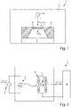
- FIG 1 shows a schematic representation of the pressure sensor 1 according to the invention. This comprises a housing 2, a pressure sensor element 3 arranged in the housing 2 and a lighting means 4 also arranged in the housing.
- the pressure sensor element 3 introduced into the housing 2 has a semiconductor material, preferably silicon.
- a measuring membrane 5 is introduced into the pressure sensor element 3, for example by means of an etching process.
- measuring diaphragm 5 is subjected to a first pressure p 1 , e.g. atmospheric pressure, on a first side, and a second pressure p 2 , e.g measuring media pressure, supplied.
- the measuring diaphragm again includes four resistance elements 6, which are generated, for example, by doping the semiconductor material.
- the resistance elements 6 integrated into the measuring membrane 5 in this way are typically arranged in the edge region of the measuring membrane 5 in order to detect the pressure-dependent deflection of the measuring membrane 5 in the form of a change in resistance. Based on the changes in resistance of the resistance elements 6, the pressure sensor 1 can determine or output a measured pressure variable.
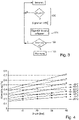
- FIG. 2 shows a schematic block diagram of the pressure sensor 1 according to the invention, which in addition to the light source 4 with a corresponding light source drive unit 7 and the resistance elements 6 also includes a control/evaluation unit 8 .
- the resistance elements 6 are connected to form a Wheatstone bridge 9 and the control/evaluation unit 8 is typically used to record an electrical signal 10 representing the resistance values, for example the bridge voltage signal U B .
- the control/evaluation unit 8 uses the recorded electrical signal 10, in the illustrated case the bridge voltage U B , to determine a measured pressure variable.
- FIG. 4 shows an experimentally determined measurement curve.
- the optical excitation was carried out by a large number of individual optical pulses at the appropriate pressures and temperatures.
- the change or deviation in the electrical signal was recorded by averaging the recorded multiple individual signal values, the change or deviation being the difference between the electrical signal with optical excitation and the electrical signal without optical excitation.
- the detected electrical signal 10 shows a change which is due to the optical excitation. Also evident from 4 is that the electrical signal 10 is dependent on temperature and pressure, which may still have to be compensated for before a malfunction of the pressure sensor 1 can be determined. If, despite a possible temperature and pressure compensation, there is a change in the electrical signal that goes beyond the tolerance range, it can be assumed with high probability that there is a malfunction, for example a drift of the resistance elements 6 and/or a membrane rupture or membrane tear.
Applications Claiming Priority (2)
| Application Number | Priority Date | Filing Date | Title |
|---|---|---|---|
| DE102015112408.4A DE102015112408A1 (de) | 2015-07-29 | 2015-07-29 | Drucksensor und Verfahren zum Überwachen eines Drucksensors |
| PCT/EP2016/064378 WO2017016757A1 (de) | 2015-07-29 | 2016-06-22 | Drucksensor und verfahren zum überwachen eines drucksensors |
Publications (2)
| Publication Number | Publication Date |
|---|---|
| EP3329236A1 EP3329236A1 (de) | 2018-06-06 |
| EP3329236B1 true EP3329236B1 (de) | 2022-10-19 |
Family
ID=56148418
Family Applications (1)
| Application Number | Title | Priority Date | Filing Date |
|---|---|---|---|
| EP16730853.5A Active EP3329236B1 (de) | 2015-07-29 | 2016-06-22 | Drucksensor und verfahren zum überwachen eines drucksensors |
Country Status (5)
| Country | Link |
|---|---|
| US (1) | US10712219B2 (zh) |
| EP (1) | EP3329236B1 (zh) |
| CN (1) | CN107850504B (zh) |
| DE (1) | DE102015112408A1 (zh) |
| WO (1) | WO2017016757A1 (zh) |
Families Citing this family (1)
| Publication number | Priority date | Publication date | Assignee | Title |
|---|---|---|---|---|
| CN111661815B (zh) * | 2020-06-04 | 2021-01-19 | 上海南麟集成电路有限公司 | 一种mems触觉传感器及其制作方法 |
Family Cites Families (23)
| Publication number | Priority date | Publication date | Assignee | Title |
|---|---|---|---|---|
| US3714829A (en) * | 1970-06-29 | 1973-02-06 | Beckman Instruments Inc | Pressure measuring system |
| JPS5595373A (en) | 1979-01-11 | 1980-07-19 | Nissan Motor Co Ltd | Semiconductor pressure sensor |
| US4621503A (en) | 1984-04-04 | 1986-11-11 | General Electric Company | Pressure sensing devices and methods, control devices and methods of operating same, smart pressure switches, air conditioning systems and devices for controlling same |
| US4631401A (en) | 1984-06-06 | 1986-12-23 | Dieterich Standard Corporation | Optic sensors |
| GB8530809D0 (en) | 1985-12-13 | 1986-01-22 | Gen Electric Co Plc | Sensor |
| US5101664A (en) | 1990-10-15 | 1992-04-07 | United Technologies Corporation | Optical pressure transducer |
| CN2089627U (zh) * | 1990-12-29 | 1991-11-27 | 姜珂 | 抗震光电脉动压力数显表 |
| US5804815A (en) * | 1996-07-05 | 1998-09-08 | Sandia Corporation | GaAs photoconductive semiconductor switch |
| GB9808061D0 (en) * | 1998-04-16 | 1998-06-17 | Cambridge Display Tech Ltd | Polymer devices |
| JP2000234977A (ja) * | 1999-02-16 | 2000-08-29 | Fujikura Ltd | 静電容量式半導体圧力センサ及びその試験方法 |
| DE10144230A1 (de) * | 2001-09-07 | 2003-03-27 | Endress & Hauser Gmbh & Co Kg | Druckmeßgerät |
| DE10200779B4 (de) * | 2002-01-10 | 2009-03-12 | Endress + Hauser Gmbh + Co. Kg | Druckmittler mit Modul zur Erkennung von Membranbrüchen und Druckmessgerät zur Erkennung von Membranbrüchen |
| US7543501B2 (en) | 2005-10-27 | 2009-06-09 | Advanced Research Corporation | Self-calibrating pressure sensor |
| DE102006062552B4 (de) * | 2006-12-29 | 2009-12-24 | Bartels Mikrotechnik Gmbh | Verfahren und Vorrichtung zur Durchflussmessung |
| CN100465585C (zh) * | 2007-04-28 | 2009-03-04 | 西南石油大学 | 一种钻井井架平面摆动测试装置 |
| EP2167931B1 (en) * | 2007-07-12 | 2015-11-04 | ABB Research Ltd. | Pressure sensor |
| US8320154B2 (en) * | 2007-08-08 | 2012-11-27 | National Institute For Materials Science | Switching element and application of the same |
| CN201273820Y (zh) | 2008-09-11 | 2009-07-15 | 韩力 | 一种光电式微压传感器 |
| JP5654760B2 (ja) * | 2010-03-02 | 2015-01-14 | キヤノン株式会社 | 光素子 |
| WO2011143384A1 (en) | 2010-05-12 | 2011-11-17 | Parker-Hannifin Corporation | Sensor sleeve for health monitoring an article |
| CN203260168U (zh) * | 2013-04-08 | 2013-10-30 | 天津市浦海新技术有限公司 | 一种报警控制器 |
| JP2015118016A (ja) * | 2013-12-18 | 2015-06-25 | セイコーエプソン株式会社 | 物理量センサー、圧力センサー、高度計、電子機器および移動体 |
| DE102015121859A1 (de) * | 2015-12-15 | 2017-06-22 | Endress+Hauser Gmbh+Co. Kg | Drucksensor und Verfahren zum Bedienen eines Drucksensors |
-
2015
- 2015-07-29 DE DE102015112408.4A patent/DE102015112408A1/de not_active Withdrawn
-
2016
- 2016-06-22 CN CN201680041837.8A patent/CN107850504B/zh active Active
- 2016-06-22 US US15/748,529 patent/US10712219B2/en active Active
- 2016-06-22 WO PCT/EP2016/064378 patent/WO2017016757A1/de active Application Filing
- 2016-06-22 EP EP16730853.5A patent/EP3329236B1/de active Active
Also Published As
| Publication number | Publication date |
|---|---|
| EP3329236A1 (de) | 2018-06-06 |
| DE102015112408A1 (de) | 2017-02-02 |
| WO2017016757A1 (de) | 2017-02-02 |
| US20180217017A1 (en) | 2018-08-02 |
| CN107850504A (zh) | 2018-03-27 |
| CN107850504B (zh) | 2020-05-26 |
| US10712219B2 (en) | 2020-07-14 |
Similar Documents
| Publication | Publication Date | Title |
|---|---|---|
| EP2726833B1 (de) | Verfahren zum betreiben eines absolut- oder relativdrucksensors mit einem kapazitiven wandler | |
| DE102009002682B4 (de) | Einrichtung und Verfahren zur Residuenauswertung eines Residuums zur Erkennung von Systemfehlern im Systemverhalten eines Systems eines Flugzeugs | |
| EP3265754B1 (de) | Messbrückenanordnung mit verbesserter fehlererkennung | |
| DE102006043499A1 (de) | Verfahren und Vorrichtung zur Diagnose von Flüssigkeitsverlusten in mit Druck übertragenden Flüssigkeiten gefüllten Druckmessaufnehmern | |
| DE102008020862B3 (de) | Messumformer zur Prozessinstrumentierung und Verfahren zur Überwachung des Zustands dessen Sensors | |
| WO2014095245A1 (de) | Verfahren und vorrichtung zur bestimmung eines zustands eines in einem prozessbehälter integrierten messaufnehmers | |
| EP1612531A2 (de) | Mikromechanische Struktur | |
| EP2743519A1 (de) | Ventileinrichtung, Ventilanordnung und Verfahren zum Kalibrieren einer Ventilanordnung | |
| EP3329236B1 (de) | Drucksensor und verfahren zum überwachen eines drucksensors | |
| WO2008061832A2 (de) | Selbsttest bei einem mikromechanischen drucksensor | |
| DE102006040408A1 (de) | Verfahren zum Betrieb einer Fühleranordnung | |
| EP3768558B1 (de) | Sensoranordnung für ein fahrzeug und verfahren zur überwachung eines sensors | |
| WO2012098136A1 (de) | Druckmessumformer | |
| WO2016102119A1 (de) | Druckwandler und verfahren zum betreiben eines solchen | |
| DE102015121859A1 (de) | Drucksensor und Verfahren zum Bedienen eines Drucksensors | |
| DE102006058269B4 (de) | Verfahren zur Kalibrierung mindestens eines Drucksensors und entsprechender Drucksensor | |
| DE102012112971A1 (de) | Verfahren zur Ermittlung einer Fehlfunktion eines Membrandruckmittlers | |
| EP2581890B1 (de) | Verfahren zur Erhöhung der Fehlalarmsicherheit eines Brandmelders | |
| DE102013113690A1 (de) | Druckmessgerät und Verfahren zu dessen Inbetriebnahme an einem Einsatzort | |
| DE102018116850A1 (de) | Drucksensorelement mit Glasbarrierenmaterial konfiguriert für erhöhte kapazitive Antwort | |
| DE102014119398A1 (de) | Differenzdruckwandler und ein Verfahren zum Betreiben eines solchen | |
| DE102020116702A1 (de) | Druckmessgerät | |
| DE102022202295A1 (de) | Umgebungssensor und Verfahren zum Betreiben eines Umgebungssensors | |
| DE102021120739A1 (de) | Sensorvorrichtung | |
| DE102021119383A1 (de) | Kapazitiver Grenzstandschalter |
Legal Events
| Date | Code | Title | Description |
|---|---|---|---|
| STAA | Information on the status of an ep patent application or granted ep patent |
Free format text: STATUS: THE INTERNATIONAL PUBLICATION HAS BEEN MADE |
|
| PUAI | Public reference made under article 153(3) epc to a published international application that has entered the european phase |
Free format text: ORIGINAL CODE: 0009012 |
|
| STAA | Information on the status of an ep patent application or granted ep patent |
Free format text: STATUS: REQUEST FOR EXAMINATION WAS MADE |
|
| 17P | Request for examination filed |
Effective date: 20171124 |
|
| AK | Designated contracting states |
Kind code of ref document: A1 Designated state(s): AL AT BE BG CH CY CZ DE DK EE ES FI FR GB GR HR HU IE IS IT LI LT LU LV MC MK MT NL NO PL PT RO RS SE SI SK SM TR |
|
| AX | Request for extension of the european patent |
Extension state: BA ME |
|
| DAV | Request for validation of the european patent (deleted) | ||
| DAX | Request for extension of the european patent (deleted) | ||
| STAA | Information on the status of an ep patent application or granted ep patent |
Free format text: STATUS: EXAMINATION IS IN PROGRESS |
|
| 17Q | First examination report despatched |
Effective date: 20200204 |
|
| STAA | Information on the status of an ep patent application or granted ep patent |
Free format text: STATUS: EXAMINATION IS IN PROGRESS |
|
| GRAP | Despatch of communication of intention to grant a patent |
Free format text: ORIGINAL CODE: EPIDOSNIGR1 |
|
| STAA | Information on the status of an ep patent application or granted ep patent |
Free format text: STATUS: GRANT OF PATENT IS INTENDED |
|
| INTG | Intention to grant announced |
Effective date: 20220531 |
|
| GRAS | Grant fee paid |
Free format text: ORIGINAL CODE: EPIDOSNIGR3 |
|
| GRAA | (expected) grant |
Free format text: ORIGINAL CODE: 0009210 |
|
| STAA | Information on the status of an ep patent application or granted ep patent |
Free format text: STATUS: THE PATENT HAS BEEN GRANTED |
|
| AK | Designated contracting states |
Kind code of ref document: B1 Designated state(s): AL AT BE BG CH CY CZ DE DK EE ES FI FR GB GR HR HU IE IS IT LI LT LU LV MC MK MT NL NO PL PT RO RS SE SI SK SM TR |
|
| REG | Reference to a national code |
Ref country code: GB Ref legal event code: FG4D Free format text: NOT ENGLISH |
|
| REG | Reference to a national code |
Ref country code: CH Ref legal event code: EP |
|
| REG | Reference to a national code |
Ref country code: IE Ref legal event code: FG4D Free format text: LANGUAGE OF EP DOCUMENT: GERMAN |
|
| REG | Reference to a national code |
Ref country code: DE Ref legal event code: R096 Ref document number: 502016015363 Country of ref document: DE |
|
| REG | Reference to a national code |
Ref country code: AT Ref legal event code: REF Ref document number: 1525827 Country of ref document: AT Kind code of ref document: T Effective date: 20221115 |
|
| REG | Reference to a national code |
Ref country code: LT Ref legal event code: MG9D |
|
| REG | Reference to a national code |
Ref country code: NL Ref legal event code: MP Effective date: 20221019 |
|
| PG25 | Lapsed in a contracting state [announced via postgrant information from national office to epo] |
Ref country code: NL Free format text: LAPSE BECAUSE OF FAILURE TO SUBMIT A TRANSLATION OF THE DESCRIPTION OR TO PAY THE FEE WITHIN THE PRESCRIBED TIME-LIMIT Effective date: 20221019 |
|
| PG25 | Lapsed in a contracting state [announced via postgrant information from national office to epo] |
Ref country code: SE Free format text: LAPSE BECAUSE OF FAILURE TO SUBMIT A TRANSLATION OF THE DESCRIPTION OR TO PAY THE FEE WITHIN THE PRESCRIBED TIME-LIMIT Effective date: 20221019 Ref country code: PT Free format text: LAPSE BECAUSE OF FAILURE TO SUBMIT A TRANSLATION OF THE DESCRIPTION OR TO PAY THE FEE WITHIN THE PRESCRIBED TIME-LIMIT Effective date: 20230220 Ref country code: NO Free format text: LAPSE BECAUSE OF FAILURE TO SUBMIT A TRANSLATION OF THE DESCRIPTION OR TO PAY THE FEE WITHIN THE PRESCRIBED TIME-LIMIT Effective date: 20230119 Ref country code: LT Free format text: LAPSE BECAUSE OF FAILURE TO SUBMIT A TRANSLATION OF THE DESCRIPTION OR TO PAY THE FEE WITHIN THE PRESCRIBED TIME-LIMIT Effective date: 20221019 Ref country code: FI Free format text: LAPSE BECAUSE OF FAILURE TO SUBMIT A TRANSLATION OF THE DESCRIPTION OR TO PAY THE FEE WITHIN THE PRESCRIBED TIME-LIMIT Effective date: 20221019 Ref country code: ES Free format text: LAPSE BECAUSE OF FAILURE TO SUBMIT A TRANSLATION OF THE DESCRIPTION OR TO PAY THE FEE WITHIN THE PRESCRIBED TIME-LIMIT Effective date: 20221019 |
|
| PG25 | Lapsed in a contracting state [announced via postgrant information from national office to epo] |
Ref country code: RS Free format text: LAPSE BECAUSE OF FAILURE TO SUBMIT A TRANSLATION OF THE DESCRIPTION OR TO PAY THE FEE WITHIN THE PRESCRIBED TIME-LIMIT Effective date: 20221019 Ref country code: PL Free format text: LAPSE BECAUSE OF FAILURE TO SUBMIT A TRANSLATION OF THE DESCRIPTION OR TO PAY THE FEE WITHIN THE PRESCRIBED TIME-LIMIT Effective date: 20221019 Ref country code: LV Free format text: LAPSE BECAUSE OF FAILURE TO SUBMIT A TRANSLATION OF THE DESCRIPTION OR TO PAY THE FEE WITHIN THE PRESCRIBED TIME-LIMIT Effective date: 20221019 Ref country code: IS Free format text: LAPSE BECAUSE OF FAILURE TO SUBMIT A TRANSLATION OF THE DESCRIPTION OR TO PAY THE FEE WITHIN THE PRESCRIBED TIME-LIMIT Effective date: 20230219 Ref country code: HR Free format text: LAPSE BECAUSE OF FAILURE TO SUBMIT A TRANSLATION OF THE DESCRIPTION OR TO PAY THE FEE WITHIN THE PRESCRIBED TIME-LIMIT Effective date: 20221019 Ref country code: GR Free format text: LAPSE BECAUSE OF FAILURE TO SUBMIT A TRANSLATION OF THE DESCRIPTION OR TO PAY THE FEE WITHIN THE PRESCRIBED TIME-LIMIT Effective date: 20230120 |
|
| P01 | Opt-out of the competence of the unified patent court (upc) registered |
Effective date: 20230601 |
|
| REG | Reference to a national code |
Ref country code: DE Ref legal event code: R097 Ref document number: 502016015363 Country of ref document: DE |
|
| PG25 | Lapsed in a contracting state [announced via postgrant information from national office to epo] |
Ref country code: SM Free format text: LAPSE BECAUSE OF FAILURE TO SUBMIT A TRANSLATION OF THE DESCRIPTION OR TO PAY THE FEE WITHIN THE PRESCRIBED TIME-LIMIT Effective date: 20221019 Ref country code: RO Free format text: LAPSE BECAUSE OF FAILURE TO SUBMIT A TRANSLATION OF THE DESCRIPTION OR TO PAY THE FEE WITHIN THE PRESCRIBED TIME-LIMIT Effective date: 20221019 Ref country code: EE Free format text: LAPSE BECAUSE OF FAILURE TO SUBMIT A TRANSLATION OF THE DESCRIPTION OR TO PAY THE FEE WITHIN THE PRESCRIBED TIME-LIMIT Effective date: 20221019 Ref country code: DK Free format text: LAPSE BECAUSE OF FAILURE TO SUBMIT A TRANSLATION OF THE DESCRIPTION OR TO PAY THE FEE WITHIN THE PRESCRIBED TIME-LIMIT Effective date: 20221019 Ref country code: CZ Free format text: LAPSE BECAUSE OF FAILURE TO SUBMIT A TRANSLATION OF THE DESCRIPTION OR TO PAY THE FEE WITHIN THE PRESCRIBED TIME-LIMIT Effective date: 20221019 |
|
| PGFP | Annual fee paid to national office [announced via postgrant information from national office to epo] |
Ref country code: DE Payment date: 20230620 Year of fee payment: 8 |
|
| PLBE | No opposition filed within time limit |
Free format text: ORIGINAL CODE: 0009261 |
|
| STAA | Information on the status of an ep patent application or granted ep patent |
Free format text: STATUS: NO OPPOSITION FILED WITHIN TIME LIMIT |
|
| PG25 | Lapsed in a contracting state [announced via postgrant information from national office to epo] |
Ref country code: SK Free format text: LAPSE BECAUSE OF FAILURE TO SUBMIT A TRANSLATION OF THE DESCRIPTION OR TO PAY THE FEE WITHIN THE PRESCRIBED TIME-LIMIT Effective date: 20221019 Ref country code: AL Free format text: LAPSE BECAUSE OF FAILURE TO SUBMIT A TRANSLATION OF THE DESCRIPTION OR TO PAY THE FEE WITHIN THE PRESCRIBED TIME-LIMIT Effective date: 20221019 |
|
| 26N | No opposition filed |
Effective date: 20230720 |
|
| PG25 | Lapsed in a contracting state [announced via postgrant information from national office to epo] |
Ref country code: SI Free format text: LAPSE BECAUSE OF FAILURE TO SUBMIT A TRANSLATION OF THE DESCRIPTION OR TO PAY THE FEE WITHIN THE PRESCRIBED TIME-LIMIT Effective date: 20221019 |
|
| PG25 | Lapsed in a contracting state [announced via postgrant information from national office to epo] |
Ref country code: MC Free format text: LAPSE BECAUSE OF FAILURE TO SUBMIT A TRANSLATION OF THE DESCRIPTION OR TO PAY THE FEE WITHIN THE PRESCRIBED TIME-LIMIT Effective date: 20221019 |
|
| PG25 | Lapsed in a contracting state [announced via postgrant information from national office to epo] |
Ref country code: MC Free format text: LAPSE BECAUSE OF FAILURE TO SUBMIT A TRANSLATION OF THE DESCRIPTION OR TO PAY THE FEE WITHIN THE PRESCRIBED TIME-LIMIT Effective date: 20221019 |
|
| REG | Reference to a national code |
Ref country code: CH Ref legal event code: PL |
|
| REG | Reference to a national code |
Ref country code: BE Ref legal event code: MM Effective date: 20230630 |
|
| GBPC | Gb: european patent ceased through non-payment of renewal fee |
Effective date: 20230622 |
|
| PG25 | Lapsed in a contracting state [announced via postgrant information from national office to epo] |
Ref country code: LU Free format text: LAPSE BECAUSE OF NON-PAYMENT OF DUE FEES Effective date: 20230622 |
|
| REG | Reference to a national code |
Ref country code: IE Ref legal event code: MM4A |
|
| PG25 | Lapsed in a contracting state [announced via postgrant information from national office to epo] |
Ref country code: LU Free format text: LAPSE BECAUSE OF NON-PAYMENT OF DUE FEES Effective date: 20230622 |
|
| PG25 | Lapsed in a contracting state [announced via postgrant information from national office to epo] |
Ref country code: IE Free format text: LAPSE BECAUSE OF NON-PAYMENT OF DUE FEES Effective date: 20230622 |
|
| PG25 | Lapsed in a contracting state [announced via postgrant information from national office to epo] |
Ref country code: IE Free format text: LAPSE BECAUSE OF NON-PAYMENT OF DUE FEES Effective date: 20230622 Ref country code: CH Free format text: LAPSE BECAUSE OF NON-PAYMENT OF DUE FEES Effective date: 20230630 Ref country code: GB Free format text: LAPSE BECAUSE OF NON-PAYMENT OF DUE FEES Effective date: 20230622 |