EP3329129B1 - Hydraulischer antrieb zum ausführen einer linearen bewegung - Google Patents
Hydraulischer antrieb zum ausführen einer linearen bewegung Download PDFInfo
- Publication number
- EP3329129B1 EP3329129B1 EP16736063.5A EP16736063A EP3329129B1 EP 3329129 B1 EP3329129 B1 EP 3329129B1 EP 16736063 A EP16736063 A EP 16736063A EP 3329129 B1 EP3329129 B1 EP 3329129B1
- Authority
- EP
- European Patent Office
- Prior art keywords
- valve
- connection
- pump
- piston
- hydraulic drive
- Prior art date
- Legal status (The legal status is an assumption and is not a legal conclusion. Google has not performed a legal analysis and makes no representation as to the accuracy of the status listed.)
- Active
Links
Images

Classifications
-
- F—MECHANICAL ENGINEERING; LIGHTING; HEATING; WEAPONS; BLASTING
- F15—FLUID-PRESSURE ACTUATORS; HYDRAULICS OR PNEUMATICS IN GENERAL
- F15B—SYSTEMS ACTING BY MEANS OF FLUIDS IN GENERAL; FLUID-PRESSURE ACTUATORS, e.g. SERVOMOTORS; DETAILS OF FLUID-PRESSURE SYSTEMS, NOT OTHERWISE PROVIDED FOR
- F15B20/00—Safety arrangements for fluid actuator systems; Applications of safety devices in fluid actuator systems; Emergency measures for fluid actuator systems
- F15B20/008—Valve failure
-
- F—MECHANICAL ENGINEERING; LIGHTING; HEATING; WEAPONS; BLASTING
- F16—ENGINEERING ELEMENTS AND UNITS; GENERAL MEASURES FOR PRODUCING AND MAINTAINING EFFECTIVE FUNCTIONING OF MACHINES OR INSTALLATIONS; THERMAL INSULATION IN GENERAL
- F16K—VALVES; TAPS; COCKS; ACTUATING-FLOATS; DEVICES FOR VENTING OR AERATING
- F16K31/00—Actuating devices; Operating means; Releasing devices
- F16K31/12—Actuating devices; Operating means; Releasing devices actuated by fluid
- F16K31/122—Actuating devices; Operating means; Releasing devices actuated by fluid the fluid acting on a piston
- F16K31/1221—Actuating devices; Operating means; Releasing devices actuated by fluid the fluid acting on a piston one side of the piston being spring-loaded
-
- F—MECHANICAL ENGINEERING; LIGHTING; HEATING; WEAPONS; BLASTING
- F01—MACHINES OR ENGINES IN GENERAL; ENGINE PLANTS IN GENERAL; STEAM ENGINES
- F01D—NON-POSITIVE DISPLACEMENT MACHINES OR ENGINES, e.g. STEAM TURBINES
- F01D21/00—Shutting-down of machines or engines, e.g. in emergency; Regulating, controlling, or safety means not otherwise provided for
- F01D21/16—Trip gear
- F01D21/18—Trip gear involving hydraulic means
-
- F—MECHANICAL ENGINEERING; LIGHTING; HEATING; WEAPONS; BLASTING
- F04—POSITIVE - DISPLACEMENT MACHINES FOR LIQUIDS; PUMPS FOR LIQUIDS OR ELASTIC FLUIDS
- F04B—POSITIVE-DISPLACEMENT MACHINES FOR LIQUIDS; PUMPS
- F04B39/00—Component parts, details, or accessories, of pumps or pumping systems specially adapted for elastic fluids, not otherwise provided for in, or of interest apart from, groups F04B25/00 - F04B37/00
- F04B39/08—Actuation of distribution members
-
- F—MECHANICAL ENGINEERING; LIGHTING; HEATING; WEAPONS; BLASTING
- F15—FLUID-PRESSURE ACTUATORS; HYDRAULICS OR PNEUMATICS IN GENERAL
- F15B—SYSTEMS ACTING BY MEANS OF FLUIDS IN GENERAL; FLUID-PRESSURE ACTUATORS, e.g. SERVOMOTORS; DETAILS OF FLUID-PRESSURE SYSTEMS, NOT OTHERWISE PROVIDED FOR
- F15B11/00—Servomotor systems without provision for follow-up action; Circuits therefor
- F15B11/08—Servomotor systems without provision for follow-up action; Circuits therefor with only one servomotor
-
- F—MECHANICAL ENGINEERING; LIGHTING; HEATING; WEAPONS; BLASTING
- F15—FLUID-PRESSURE ACTUATORS; HYDRAULICS OR PNEUMATICS IN GENERAL
- F15B—SYSTEMS ACTING BY MEANS OF FLUIDS IN GENERAL; FLUID-PRESSURE ACTUATORS, e.g. SERVOMOTORS; DETAILS OF FLUID-PRESSURE SYSTEMS, NOT OTHERWISE PROVIDED FOR
- F15B15/00—Fluid-actuated devices for displacing a member from one position to another; Gearing associated therewith
- F15B15/20—Other details, e.g. assembly with regulating devices
- F15B15/28—Means for indicating the position, e.g. end of stroke
- F15B15/2815—Position sensing, i.e. means for continuous measurement of position, e.g. LVDT
-
- F—MECHANICAL ENGINEERING; LIGHTING; HEATING; WEAPONS; BLASTING
- F15—FLUID-PRESSURE ACTUATORS; HYDRAULICS OR PNEUMATICS IN GENERAL
- F15B—SYSTEMS ACTING BY MEANS OF FLUIDS IN GENERAL; FLUID-PRESSURE ACTUATORS, e.g. SERVOMOTORS; DETAILS OF FLUID-PRESSURE SYSTEMS, NOT OTHERWISE PROVIDED FOR
- F15B20/00—Safety arrangements for fluid actuator systems; Applications of safety devices in fluid actuator systems; Emergency measures for fluid actuator systems
-
- F—MECHANICAL ENGINEERING; LIGHTING; HEATING; WEAPONS; BLASTING
- F15—FLUID-PRESSURE ACTUATORS; HYDRAULICS OR PNEUMATICS IN GENERAL
- F15B—SYSTEMS ACTING BY MEANS OF FLUIDS IN GENERAL; FLUID-PRESSURE ACTUATORS, e.g. SERVOMOTORS; DETAILS OF FLUID-PRESSURE SYSTEMS, NOT OTHERWISE PROVIDED FOR
- F15B20/00—Safety arrangements for fluid actuator systems; Applications of safety devices in fluid actuator systems; Emergency measures for fluid actuator systems
- F15B20/007—Overload
-
- F—MECHANICAL ENGINEERING; LIGHTING; HEATING; WEAPONS; BLASTING
- F15—FLUID-PRESSURE ACTUATORS; HYDRAULICS OR PNEUMATICS IN GENERAL
- F15B—SYSTEMS ACTING BY MEANS OF FLUIDS IN GENERAL; FLUID-PRESSURE ACTUATORS, e.g. SERVOMOTORS; DETAILS OF FLUID-PRESSURE SYSTEMS, NOT OTHERWISE PROVIDED FOR
- F15B21/00—Common features of fluid actuator systems; Fluid-pressure actuator systems or details thereof, not covered by any other group of this subclass
- F15B21/04—Special measures taken in connection with the properties of the fluid
- F15B21/042—Controlling the temperature of the fluid
- F15B21/0423—Cooling
-
- F—MECHANICAL ENGINEERING; LIGHTING; HEATING; WEAPONS; BLASTING
- F16—ENGINEERING ELEMENTS AND UNITS; GENERAL MEASURES FOR PRODUCING AND MAINTAINING EFFECTIVE FUNCTIONING OF MACHINES OR INSTALLATIONS; THERMAL INSULATION IN GENERAL
- F16K—VALVES; TAPS; COCKS; ACTUATING-FLOATS; DEVICES FOR VENTING OR AERATING
- F16K31/00—Actuating devices; Operating means; Releasing devices
- F16K31/12—Actuating devices; Operating means; Releasing devices actuated by fluid
- F16K31/122—Actuating devices; Operating means; Releasing devices actuated by fluid the fluid acting on a piston
- F16K31/124—Actuating devices; Operating means; Releasing devices actuated by fluid the fluid acting on a piston servo actuated
-
- F—MECHANICAL ENGINEERING; LIGHTING; HEATING; WEAPONS; BLASTING
- F15—FLUID-PRESSURE ACTUATORS; HYDRAULICS OR PNEUMATICS IN GENERAL
- F15B—SYSTEMS ACTING BY MEANS OF FLUIDS IN GENERAL; FLUID-PRESSURE ACTUATORS, e.g. SERVOMOTORS; DETAILS OF FLUID-PRESSURE SYSTEMS, NOT OTHERWISE PROVIDED FOR
- F15B1/00—Installations or systems with accumulators; Supply reservoir or sump assemblies
- F15B1/02—Installations or systems with accumulators
- F15B1/021—Installations or systems with accumulators used for damping
-
- F—MECHANICAL ENGINEERING; LIGHTING; HEATING; WEAPONS; BLASTING
- F15—FLUID-PRESSURE ACTUATORS; HYDRAULICS OR PNEUMATICS IN GENERAL
- F15B—SYSTEMS ACTING BY MEANS OF FLUIDS IN GENERAL; FLUID-PRESSURE ACTUATORS, e.g. SERVOMOTORS; DETAILS OF FLUID-PRESSURE SYSTEMS, NOT OTHERWISE PROVIDED FOR
- F15B15/00—Fluid-actuated devices for displacing a member from one position to another; Gearing associated therewith
- F15B15/20—Other details, e.g. assembly with regulating devices
- F15B15/28—Means for indicating the position, e.g. end of stroke
-
- F—MECHANICAL ENGINEERING; LIGHTING; HEATING; WEAPONS; BLASTING
- F15—FLUID-PRESSURE ACTUATORS; HYDRAULICS OR PNEUMATICS IN GENERAL
- F15B—SYSTEMS ACTING BY MEANS OF FLUIDS IN GENERAL; FLUID-PRESSURE ACTUATORS, e.g. SERVOMOTORS; DETAILS OF FLUID-PRESSURE SYSTEMS, NOT OTHERWISE PROVIDED FOR
- F15B2211/00—Circuits for servomotor systems
- F15B2211/20—Fluid pressure source, e.g. accumulator or variable axial piston pump
- F15B2211/205—Systems with pumps
- F15B2211/20507—Type of prime mover
- F15B2211/20515—Electric motor
-
- F—MECHANICAL ENGINEERING; LIGHTING; HEATING; WEAPONS; BLASTING
- F15—FLUID-PRESSURE ACTUATORS; HYDRAULICS OR PNEUMATICS IN GENERAL
- F15B—SYSTEMS ACTING BY MEANS OF FLUIDS IN GENERAL; FLUID-PRESSURE ACTUATORS, e.g. SERVOMOTORS; DETAILS OF FLUID-PRESSURE SYSTEMS, NOT OTHERWISE PROVIDED FOR
- F15B2211/00—Circuits for servomotor systems
- F15B2211/20—Fluid pressure source, e.g. accumulator or variable axial piston pump
- F15B2211/205—Systems with pumps
- F15B2211/2053—Type of pump
- F15B2211/20561—Type of pump reversible
-
- F—MECHANICAL ENGINEERING; LIGHTING; HEATING; WEAPONS; BLASTING
- F15—FLUID-PRESSURE ACTUATORS; HYDRAULICS OR PNEUMATICS IN GENERAL
- F15B—SYSTEMS ACTING BY MEANS OF FLUIDS IN GENERAL; FLUID-PRESSURE ACTUATORS, e.g. SERVOMOTORS; DETAILS OF FLUID-PRESSURE SYSTEMS, NOT OTHERWISE PROVIDED FOR
- F15B2211/00—Circuits for servomotor systems
- F15B2211/40—Flow control
- F15B2211/415—Flow control characterised by the connections of the flow control means in the circuit
- F15B2211/41581—Flow control characterised by the connections of the flow control means in the circuit being connected to an output member and a return line
-
- F—MECHANICAL ENGINEERING; LIGHTING; HEATING; WEAPONS; BLASTING
- F15—FLUID-PRESSURE ACTUATORS; HYDRAULICS OR PNEUMATICS IN GENERAL
- F15B—SYSTEMS ACTING BY MEANS OF FLUIDS IN GENERAL; FLUID-PRESSURE ACTUATORS, e.g. SERVOMOTORS; DETAILS OF FLUID-PRESSURE SYSTEMS, NOT OTHERWISE PROVIDED FOR
- F15B2211/00—Circuits for servomotor systems
- F15B2211/50—Pressure control
- F15B2211/515—Pressure control characterised by the connections of the pressure control means in the circuit
-
- F—MECHANICAL ENGINEERING; LIGHTING; HEATING; WEAPONS; BLASTING
- F15—FLUID-PRESSURE ACTUATORS; HYDRAULICS OR PNEUMATICS IN GENERAL
- F15B—SYSTEMS ACTING BY MEANS OF FLUIDS IN GENERAL; FLUID-PRESSURE ACTUATORS, e.g. SERVOMOTORS; DETAILS OF FLUID-PRESSURE SYSTEMS, NOT OTHERWISE PROVIDED FOR
- F15B2211/00—Circuits for servomotor systems
- F15B2211/50—Pressure control
- F15B2211/515—Pressure control characterised by the connections of the pressure control means in the circuit
- F15B2211/5151—Pressure control characterised by the connections of the pressure control means in the circuit being connected to a pressure source and a directional control valve
-
- F—MECHANICAL ENGINEERING; LIGHTING; HEATING; WEAPONS; BLASTING
- F15—FLUID-PRESSURE ACTUATORS; HYDRAULICS OR PNEUMATICS IN GENERAL
- F15B—SYSTEMS ACTING BY MEANS OF FLUIDS IN GENERAL; FLUID-PRESSURE ACTUATORS, e.g. SERVOMOTORS; DETAILS OF FLUID-PRESSURE SYSTEMS, NOT OTHERWISE PROVIDED FOR
- F15B2211/00—Circuits for servomotor systems
- F15B2211/60—Circuit components or control therefor
- F15B2211/63—Electronic controllers
- F15B2211/6303—Electronic controllers using input signals
- F15B2211/6306—Electronic controllers using input signals representing a pressure
- F15B2211/6313—Electronic controllers using input signals representing a pressure the pressure being a load pressure
-
- F—MECHANICAL ENGINEERING; LIGHTING; HEATING; WEAPONS; BLASTING
- F15—FLUID-PRESSURE ACTUATORS; HYDRAULICS OR PNEUMATICS IN GENERAL
- F15B—SYSTEMS ACTING BY MEANS OF FLUIDS IN GENERAL; FLUID-PRESSURE ACTUATORS, e.g. SERVOMOTORS; DETAILS OF FLUID-PRESSURE SYSTEMS, NOT OTHERWISE PROVIDED FOR
- F15B2211/00—Circuits for servomotor systems
- F15B2211/60—Circuit components or control therefor
- F15B2211/63—Electronic controllers
- F15B2211/6303—Electronic controllers using input signals
- F15B2211/6343—Electronic controllers using input signals representing a temperature
-
- F—MECHANICAL ENGINEERING; LIGHTING; HEATING; WEAPONS; BLASTING
- F15—FLUID-PRESSURE ACTUATORS; HYDRAULICS OR PNEUMATICS IN GENERAL
- F15B—SYSTEMS ACTING BY MEANS OF FLUIDS IN GENERAL; FLUID-PRESSURE ACTUATORS, e.g. SERVOMOTORS; DETAILS OF FLUID-PRESSURE SYSTEMS, NOT OTHERWISE PROVIDED FOR
- F15B2211/00—Circuits for servomotor systems
- F15B2211/70—Output members, e.g. hydraulic motors or cylinders or control therefor
- F15B2211/705—Output members, e.g. hydraulic motors or cylinders or control therefor characterised by the type of output members or actuators
- F15B2211/7051—Linear output members
- F15B2211/7052—Single-acting output members
-
- F—MECHANICAL ENGINEERING; LIGHTING; HEATING; WEAPONS; BLASTING
- F15—FLUID-PRESSURE ACTUATORS; HYDRAULICS OR PNEUMATICS IN GENERAL
- F15B—SYSTEMS ACTING BY MEANS OF FLUIDS IN GENERAL; FLUID-PRESSURE ACTUATORS, e.g. SERVOMOTORS; DETAILS OF FLUID-PRESSURE SYSTEMS, NOT OTHERWISE PROVIDED FOR
- F15B2211/00—Circuits for servomotor systems
- F15B2211/70—Output members, e.g. hydraulic motors or cylinders or control therefor
- F15B2211/705—Output members, e.g. hydraulic motors or cylinders or control therefor characterised by the type of output members or actuators
- F15B2211/7051—Linear output members
- F15B2211/7053—Double-acting output members
-
- F—MECHANICAL ENGINEERING; LIGHTING; HEATING; WEAPONS; BLASTING
- F15—FLUID-PRESSURE ACTUATORS; HYDRAULICS OR PNEUMATICS IN GENERAL
- F15B—SYSTEMS ACTING BY MEANS OF FLUIDS IN GENERAL; FLUID-PRESSURE ACTUATORS, e.g. SERVOMOTORS; DETAILS OF FLUID-PRESSURE SYSTEMS, NOT OTHERWISE PROVIDED FOR
- F15B2211/00—Circuits for servomotor systems
- F15B2211/80—Other types of control related to particular problems or conditions
- F15B2211/86—Control during or prevention of abnormal conditions
- F15B2211/863—Control during or prevention of abnormal conditions the abnormal condition being a hydraulic or pneumatic failure
Definitions
- the invention relates to a hydraulic drive for carrying out a linear movement.
- Hydraulic drives are used, among other things, for opening and closing valves, e.g. for gas turbines. Since in this context, especially in an emergency, large forces have to be applied to close the valve in a short time and possibly large adjustment ranges, hydraulic drives are preferably used.
- a linear movement can be generated by combining, for example, a rotary pump with a lifting cylinder.
- the axial position of the piston within the lifting cylinder is adjusted directly using the pump by building up hydrostatic pressure within the hydraulic circuit.
- the publication EP 2 620 655 A1 discloses in this regard a piston cylinder with a return spring, so that the return spring can extend the piston and a coupled valve is closed.
- the coupled valve is opened by a fluid volume flow source driven by a servo motor supplying fluid to the piston cylinder and increasing the hydrostatic pressure so that the piston is retracted.
- the fluid volume flow source can direct the working fluid in two different directions pump so that the piston can be both retracted and extended using the driven pump.
- logic connected in parallel controls a valve, for example, to connect the inflow and outflow of the piston cylinder so that the piston is extended via the return spring and the coupled valve is closed.
- a lifting cylinder is from the US 4,842,244 A known. This discloses a slow movement of a piston by opening a solenoid valve, while simultaneously switching off pump motors. The lifting cylinder is moved quickly by opening three solenoid valves at the same time and switching off the pump motors.
- an electro-hydraulic actuator for turbine valves which essentially has an actuator and a quick-action valve.
- an oil delivery unit is equipped with a variable displacement pump and an auxiliary pump.
- a final amplifier and a two-way valve are provided on the lifting cylinders to implement different operating modes.
- the drain amplifier is opened so that fluid can flow into the piston chamber via a bypass line.
- both the two-way valve and the final amplifier are opened.
- the EP 1 209 394 A2 describes an electro-hydraulic actuator, in particular for adjusting a control valve in steam turbines, and a method for controlling such a drive.
- the actuator is designed in the form of a single functional unit.
- a switching valve is provided in such a way that when opened, a flow path cross section is disproportionately increased in order to accelerate a return stroke of a piston rod.
- the working space AR and the spring space FR of the piston unit can be fluidly connected using a slide valve and the switching valve, the switching valve being controlled via the slide valve based on the fluid pressure in a channel of the control pressure line. Rapid discharge is achieved through the interaction of the two valves.
- the US 3,757,646 A discloses a safety system, including a working cylinder, a first control valve, a power means and a first valve.
- a fluid connection is made between an upper and a lower cylinder chamber in the working cylinder is provided by parallel-connected, identical first valves and check valves, the first valve being controlled by means of a control valve.
- the DE 34 32 890 A1 describes a device for monitoring physical variables in systems, such as for controlling a quick-closing valve in turbines.
- three identical 4-way solenoid valves are provided that can control the quick-closing valve of a turbine. It is intended that two of the valves are always coupled to one another in terms of flow. Furthermore, a separate test valve is provided in order to be able to carry out a partial stroke test of the flow valve.
- the EP 0 277 602 A2 discloses hydraulic systems for operating implements that are carried by a vehicle and have two hydraulic circuits each powered by a pump. There are two interconnected hydraulic circuits, each with, among other things, a pump and identical short-circuit valves as well as identical control valves. In particular, the two hydraulic circuits can be linked to one another via a check valve, so that the hydraulic circuits can supply each other with pressure medium that is not required.
- the present invention is based on the object of providing a hydraulic drive in order to convert a rotary movement into a linear movement, the hydraulic drive enabling a simple, low-maintenance, cost-efficient and flexible application independent of external components and at the same time exact positioning of the Piston is provided at any position with optimized extension speed.
- the drive according to the invention is provided with a motor, a pump, a lifting cylinder and a spring.
- the lifting cylinder has a linearly movable piston and a cylinder housing with at least a first connection and a second connection.
- the spring is arranged such that the piston is extended or retracted in the relaxed state of the spring, in each case depending on the direction of action of the spring.
- the pump can be, for example, a gear pump, preferably with low leakage, in order to achieve high delivery efficiency even with small amounts of working fluid within the hydraulic system.
- the motor is preferably a controllable motor, such as a synchronous motor or an asynchronous motor, but can also be a switchable motor that is operated in intermittent operation.
- the motor for driving the pump is a speed-controlled motor.
- the hydrostatic pressure can thus be specifically adjusted and, if necessary, adjusted or readjusted by controlling the motor within the hydraulic system.
- the present invention further has at least one first valve, with which the first connection and the second connection can be fluidly connected. It is therefore possible to bring the piston into a partially or fully extended state and into a partially or fully retracted state by means of the hydraulic system and the spring.
- a valve for a gas turbine coupled to the piston rod of the piston can be completely closed in the extended state and completely opened in the retracted state with the aid of the linearly acting piston.
- the drive according to the invention with the linearly movable piston can, in addition to the control of gas turbine valves, also be used for other applications for which a linear movement with the application of high forces is useful.
- the use of hydraulic drives is not only limited to the technical area of gas turbines.
- the system can be assembled from the individual components in the form of a modular system. This makes it possible, for example, to arrange the motor and the reservoir differently from each other and from the other components. The functionality of the individual components is not affected by their orientation or arrangement.
- the hydraulic drive can therefore be designed in a separate design as well as in a compact design. This achieves both a compact design of the hydraulic drive and flexible adaptation to the conditions in use.
- At least one second valve is provided for the underlying invention, which is connected in parallel with the first valve. It is also provided that the first valve has a maximum volumetric flow rate that is greater than the maximum volumetric flow rate of the second valve.
- the first and second valves, but also all other components of the drive according to the invention, can be designed redundantly in the sense of the present invention in order to reduce the probability of failure of the drive.
- the advantage is that the piston can be extended by opening the first and/or the second valve. Due to the different maximum volume flow rates, the piston reaches a higher extension speed when opening the first valve than can be achieved when opening the second valve.
- the first and second valves are preferably provided as spring-loaded directional control valves.
- the directional valves are also electromagnetically adjustable, so that at least one further, second switching position can be selected for the directional valves.
- the two valves return to a first switching position due to the spring-loaded design, provided there is no electromagnetic changeover of the valves.
- the user of the drive according to the invention is thus able to bring the first and/or second valve into a desired switching position independently of one another and if necessary. This results in several possible combinations for the position of the first valve and the second valve depending on the respective application (see Table 1 ) .
- the first valve and the second valve have a first switching position and a second switching position. In the first switching position, a flow path is provided through the first and/or the second valves. If one of the two valves is in the first switching position, the working fluid can flow through the respective valve from the first connection to the second connection.
- Table 1 Valve position options for various applications ⁇ /i> Operating procedures Valve switching state Normal operation / Full retraction First valve check valve Second valve check valve Fully extend First valve flow path Second valve check valve Partial extension (large positioning deviation) First valve check valve Second valve flow path
- a second switching position of the first and second valves has a flow path with a spring-loaded check valve.
- a fluid connection from the first connection to the second connection is separated.
- the separation of the flow connection occurs automatically through the respective check valve of the first and/or second valve. If there is a pressure difference from the second connection to the first connection of the cylinder housing that is sufficiently large to overcome the spring force of the check valve in the first and/or second valve, there is a fluid connection from the second connection to the first connection via the respective one Check valve can be produced automatically.
- the retraction and extension of the piston can be specifically controlled based on the flow paths.
- “automatic” in the sense of the present invention means that the valve is activated automatically or independently by the preload force of the spring contained therein and by the working fluid flowing in a specific direction and without any action by a user of the hydraulic drive is closed and the fluid connection is separated. However, if the fluid flows into the opposite direction, the spring-loaded check valve is opened according to common knowledge and a fluid connection is established when the hydrostatic pressure of the working medium on the check valve is greater than the spring force within the spring-loaded check valve.
- the pump has an inlet and an outlet.
- a working fluid can be conveyed in at least one direction.
- the pump can be rotated in the opposite direction to normal operation. When the pump rotates backwards, a negative pressure is created at the outlet of the pump so that the working fluid can be sucked in to the inlet of the pump.
- the use of a more complex and therefore more cost-intensive and maintenance-intensive bidirectional pump is not necessary for the drive according to the invention.
- a reservoir for the working fluid is provided.
- the reservoir in particular the flow outlet of the reservoir, is fluidly connected to the second connection of the cylinder housing and the inlet of the pump.
- the hydraulic drive according to the invention is provided as a closed hydraulic system.
- the reservoir can preferably be designed as a bladder accumulator or as a piston accumulator.
- the use of a piston accumulator results in lower maintenance costs and longer system running times.
- the reservoir can be used to compensate for volume and pressure fluctuations within the closed hydraulic system. Furthermore, the self-contained hydraulic system offers a cost-effective and low-maintenance solution for use. Neither external connections and infrastructure need to be provided for the present hydraulic system, nor is there a risk that contamination from outside can be introduced into the closed system during use. As a result, the system according to the invention can be used flexibly.
- a pressure relief valve is provided which is fluidly connected to the outlet of the pump and the second connection of the cylinder housing. If there is a maximum pressure that can be defined in advance When the output of the pump is reached, the output of the pump and the reservoir can be fluidly connected. A definable maximum pressure can preferably be approx. 100 bar. In this way, excessive hydraulic pressure within the closed hydraulic system and thus irreparable damage to system components is advantageously prevented.
- a clutch for transmitting a force or a torque from the motor to the pump is preferably provided between the motor and the pump.
- the coupling is in particular releasable so that power transmission between the motor and pump can be interrupted.
- At least one throttle device is provided between the first connection and the first valve and/or between the first connection and the second valve. This advantageously results in a pressure reduction in the flow inlet from the first connection of the cylinder housing to the first valve and to the second valve, whereby the speed of the lifting cylinder can be adapted to the needs of the application within a wide range. Particularly when long running times of the drive according to the invention are taken into account, an indirect reduction in the probability of failure is thereby achieved.
- a further embodiment provides that at least one temperature sensor and/or at least one pressure sensor is fluidly connected to the first connection and/or the second connection and/or the output and/or the input of the pump.
- at least one temperature sensor and/or at least one pressure sensor is fluidly connected to the first connection and/or the second connection and/or the output and/or the input of the pump.
- the object according to the invention has a position sensor on the lifting cylinder, which is preferably designed as a displacement sensor in order to determine or measure the position of the piston in the cylinder housing. It is therefore possible at any time during operation of the drive according to the invention, for example, to determine the degree of opening of a valve coupled to the piston rod. In the sense of the present invention, determining or measuring means in particular the acquisition of a value that allows conclusions to be drawn, for example, about the piston position. In addition to using a displacement transducer as a position sensor, this can also be done using any other measured value that is related to the piston position.
- the position sensor can be used to change the pump speed to control the position of the lifting cylinder.
- a spring-loaded check valve is provided such that a fluid connection from the first connection to the outlet of the pump or from the outlet of the pump to the inlet of the pump can be separated, in particular automatically or automatically disconnected. In this way, a backflow of working fluid from the first connection is prevented when the pump is at a standstill or a hydraulic short circuit from the output to the input of the pump is prevented.
- the drive according to the invention has a forced leakage throttle device on the at least one first connection and the at least one second connection. Regardless of whether the piston moves linearly due to the hydrostatic pressure conditions or a piston position is maintained, continuous movement or circulation of the working fluid in the hydraulic circuit is guaranteed when the pump is running continuously. In addition to preventing deposits within the working fluid, a homogeneous temperature distribution or heat dissipation from temperature-critical components such as the pump through the working fluid is made possible.
- a directional control valve is provided between the outlet of the pump and the inlet of the pump.
- a fluid connection from the output to the input of the pump can be separated with a first switching position and can be established with a second switching position of the directional control valve.
- a hydraulic short circuit can be achieved between the output of the pump and the input of the pump, so that the pump can circulate working fluid without affecting the position of the piston.
- the pump is driven continuously and/or as needed by the motor of the hydraulic drive.
- the working fluid is circulated and/or a linear movement of the piston is generated and/or a position of the piston is maintained in the cylinder housing, in particular kept constant over a period of time.
- both the deposition of components of the working fluid and an inhomogeneous temperature distribution within the hydraulic circuit can be prevented.
- the first valve and the second valve are switched to the second switching position. If the first and second valves are each in the second switching position, the piston position is maintained or the piston is at least partially retracted.
- the application of the first switching position to the first or second valve has different functionalities. If the first valve is brought into the first switching position, a safety closure occurs, a so-called “fail-safe" function, whereby the piston is fully extended at maximum speed, i.e. into the end position.
- the second valve is brought into the first switching position when the piston is to be extended to a definable position. By placing the second valve in the first switching position, an extension speed or positioning speed of the piston is preferably optimized.
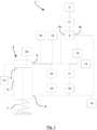
- the drive according to the invention has according to Fig. 1 a motor 2, a pump 3 and a lifting cylinder 5.
- the power is transmitted from the motor 2 to the pump 3 via a clutch 17 (see Fig. 1 , dot-dashed connection).
- the pump 3 has an inlet 3a and an outlet 3b and is preferably designed to deliver the working fluid in a specific direction.
- the output 3b of the pump 3 is fluidly connected to the check valve 14 and the pressure relief valve 13. From the check valve 14 there is a flow connection to the lifting cylinder 4, in particular to the first connection 8 of the cylinder housing 6 of the lifting cylinder 4.
- the check valve 14 is a spring-loaded check valve and is arranged in such a way that a flow connection from the connection 8 to the inlet 3a of the Pump 3 is closed automatically or automatically based on the spring force of the check valve 14 and / or based on a fluid flow.
- a fluid connection can be established between the output 3b of the pump 3 and the connection 9, provided that a hydrostatic pressure is present or is generated by the pump 3, which is sufficiently large to overcome the spring force of the spring-loaded check valve 14 and the check valve 14 to open.
- a linear retraction movement of the piston 5 in the cylinder housing 6 can be generated.
- the one intended for the lifting cylinder 4 Spring 7 is compressed and its preload force is increased by retracting the piston 5 with the piston rod into the cylinder housing. Based on this linear retraction movement of the piston 5, for example, a valve of a gas turbine coupled to the free end of the piston rod can be opened.
- a closed fluid circuit is formed across the lifting cylinder 4, so that the working fluid continuously supplied to the lifting cylinder 4 via the first connection 8 can be guided to the second connection 9 of the cylinder housing 6 and a circuit is created.
- the continuous circulation of the working fluid prevents deposits in the hydraulic system and achieves a homogeneous temperature distribution within the working fluid.
- the position of the piston 5 in the cylinder housing 6 can be adjusted in a controlled manner using the pump 3 and the spring 7.
- the pump 3 delivers working fluid via the outlet 3b in the direction of the first connection 8.
- the delivery rate of the pump 3 is reduced or the pump 3 is stopped, so that the hydrostatic pressure in the cylinder housing decreases and the preloaded spring 7 can at least partially relax.
- the extension of the piston 5 can be supported by turning the pump 3 backwards, whereby a negative pressure is generated at the outlet 3b of the pump 3 and a suction effect occurs. In this way, the position of the piston 5 and thus, for example, the degree of opening of a valve coupled to the piston rod can be continuously regulated or adjusted in a controlled manner.
- the spring-loaded check valve 14 is arranged between the inlet 3a and outlet 3b of the pump, so that when the pump 3 rotates backwards and there is a negative pressure or suction effect at the outlet 3b, working fluid is sucked in, for example, from the reservoir 12 via the check valve 14 and the pump 3 overheats is prevented.
- the spring-loaded check valve 14 it is achieved that when working fluid is conveyed through the pump 3 in the direction of the first connection 8, a flow-related The connection from the output 3b to the input 3a of the pump 3 is automatically or automatically separated.
- the connection 8 has further flow connections to the first valve 10 and the second valve 11, with throttle devices 15; 16 in the flow connections to the two valves 10; 11 are provided.
- the first valve 10 and the second valve 11 are spring-loaded and electromagnetically adjustable directional control valves with at least two switching positions.
- the first switching position of the first and second valves 10; 11 each has a flow path, so that a fluid connection from the first connection 8 to the second connection 9 of the cylinder housing 6 can be established.
- the second switching position of the two valves 10; 11 each has a spring-loaded check valve, which are arranged in such a way that a fluid connection from the first connection 8 to the second connection 9 can be separated automatically or automatically.
- a fluid connection from the second connection 9 to the first connection 8 can be established provided that there is sufficient hydrostatic pressure to reduce the spring force of the respective spring-loaded check valve of the first and/or second valve 10; 11 in the second switching position and thus open the respective valve.
- the throttle devices 15; connected upstream of the first valve 10 and the second valve 11; 16 also serve to reduce the hydrostatic pressure in the flow of the respective valve 10; 11 and enable the travel speed of the lifting cylinder 4 to be adjusted within wide control ranges.
- Fig. 1 possible to retract the piston 5 by bringing the first valve 10 and/or the second valve 11 into the second switching position. If the first or second valve 10; 11 switched to the first switching position, the hydrostatic pressure of the working medium previously built up with the pump 3 in the lifting cylinder 4 can escape via the valve in the first switching position in the direction of the second connection 9 and the reservoir 12.
- the piston 5 is extended by the preloaded spring 7 as the pressure in the lifting cylinder 4 decreases. Based on this linear movement of the piston 5 due to an outflow of the working medium via the first connection 8 and an associated pressure decrease in conjunction with the relaxation of the spring 7, for example, a valve of a gas turbine coupled to the piston rod can be closed.
- the first valve 10 preferably has a larger, maximum volume flow rate than the second valve 11. In particular, this can be achieved by different sizes of the two valves 10; 11 and cross-sectional sizes of the respective flow connection can be achieved. This results in two advantageous operating modes according to the present invention Fig. 1 .
- a first advantageous application is the complete extension of the piston 5 at maximum speed.
- the first valve 10 is opened or brought into the first switching position.
- a hydraulic short circuit occurs between the first connection 8 and the second connection 9.
- the second valve 11 remains closed or in the second switching position and embodies a spring-loaded check valve. Due to the hydrostatic pressure decreasing via the first connection 8, the preloaded spring 7 can relax and the piston 5 is extended.
- the motor 2 can be briefly accelerated in such a way that the pump 3 generates a negative pressure at the output 3b of the pump 3 by rotating in the opposite direction in order to prevent any further fluid from being conveyed in the direction of the first connection 8 or a negative pressure to create. Subsequently, in particular as soon as the piston 5 is fully extended, the motor 2 is switched off or put into a standby state.
- This process corresponds to an uncontrolled extension of the piston 5 and can be understood as a safety closure of a coupled valve.
- a valve coupled to the piston rod can be closed at maximum speed by switching the first valve 10 into the first switching position.
- several first valves 10 connected in parallel can also be provided, whereby redundancy of this functionality is achieved.
- a second advantageous application of the drive according to the invention Fig. 1 occurs when the second valve 11 is opened by switching to the first switching position, while the first valve 10 remains in the second switching position and acts as a spring-loaded check valve.
- the second valve 11 is brought into a first switching position in order to extend the piston 5 at an optimized speed to a specific, previously determined position. This corresponds to a rapid, controlled movement of the piston 5 in a direction in which the preloaded spring 7 partially relaxes.
- This method is used if an actual position has a sufficiently large deviation from the defined target position.
- the second valve 11 Shortly before reaching the previously defined target position of the piston 5, the second valve 11 is closed again and the target position is approached in a controlled manner with the help of the motor 2 or the pump 3. In contrast to the first advantageous application for completely extending the piston 5, the motor 2 or the pump 3 continues to operate continuously in this second advantageous application.
- By switching the second valve 11 into the first switching position a controlled but also faster approach to the target position is made possible than would normally be possible for the motor 2 or the pump 3 in conjunction with the preloaded spring 7.
- the target position of the piston 5 is finely adjusted as usual with the help of the spring 7 and the motor 2 or the pump 3.
- the hydraulic drive according to Fig. 1 a pressure relief valve 13 with a fluid connection to the output 3b of the pump 3.
- a maximum pressure is reached in the closed hydraulic circuit and in particular at the outlet 3b of the pump, a short circuit between the outlet 3b and the reservoir 12 is possible with the help of the pressure relief valve 13.
- the maximum pressure can preferably be set to a value of approximately 100 bar or, depending on the components used, to a lower or higher pressure.
- the pressure relief valve can open automatically or automatically and a pressure reduction or pressure equalization can be achieved, among other things, by including the reservoir 12.
- the position sensor 20 is preferably designed as a displacement sensor.
- the position sensor could also record other measured values that allow conclusions to be drawn about the position of the piston 5 within the cylinder housing 6.
- the measured value of the position sensor 20 can be compared with the number of revolutions of the motor 2 in order to obtain redundant information about the position of the piston 5.
- the position of the piston 5 is therefore particularly when the piston 5 is retracted, e.g. to open a valve coupled to the piston rod, and can be reliably detected when extending, e.g. to close a valve coupled to the piston rod.
- further proximity switches can be provided, in particular in order to detect when an end position is reached when the piston 5 is retracted or extended.
- At least one temperature sensor 19 and one pressure sensor 18 are also provided in the system according to the invention, which also have a signal connection or measurement connection to the hydraulic system (see Fig. 1 , dotted connections).
- the pressure sensor is after Fig. 1 in the immediate vicinity of the reservoir 12 and is used, among other things, to measure the preload pressure or the degree of filling when the system is filled with working fluid before commissioning. Furthermore, critical pressure conditions or leaks can also be detected with the pressure sensor during operation of the hydraulic drive. In this way it is possible to prevent overloading of the motor 2.
- the temperature sensor is according to Fig. 1 provided between the output 3b of the pump 3 and the first connection 8.
- the homogeneity of the temperature distribution within the working fluid can be measured, among other things.
- the drive according to the invention preferably has at least one interface for outputting data and for entering operating commands by a user of the system.
- an adequate computer unit can be used to process the recorded data, prepare it for the user and/or take over the regulation or control of the hydraulic drive in a user-controlled, semi-automatic or fully automatic manner.
- Fig. 2 shows the drive according to the invention Fig. 1 in a modified version.
- a circuit for continuous fluid circulation via the piston 5 using a forced leakage throttle device is not provided, as is a throttle device 16 only in the flow connection between the first connection 8 and the second valve 11 is arranged.
- the check valve 14 is according to Fig. 2 arranged between the output 3b of the pump 3 and the first connection 8.
- a further directional control valve 22 is positioned in the hydraulic circuit in order to fluidly connect and hydraulically short-circuit the output 3b of the pump 3 with the input 3a of the pump if necessary.
- the directional control valve 22 is a spring-loaded directional control valve that is electromagnetically adjustable. In the second switching position there is a flow connection from the output 3b to the input 3a of the pump 3, while the flow connection is separated in the first switching position, preferably by connecting to blind connections if necessary.
- a system according to Fig. 2 The piston 5 is retracted by the motor 2 in conjunction with the pump 3 supplying working fluid to the first connection 8. As soon as the piston 5 is completely retracted, for example detectable with a position sensor and/or proximity switches, the motor 2 is switched off. Likewise, the directional valve 22 is brought into the second switching state and thus a hydraulic short circuit is created between the output 3b and input 3a of the pump 3. The first valve 10 and the second valve 11 remain in the second switching position, that is, they represent spring-loaded check valves. The piston 5 immediately remains in the achieved position due to the position of the directional control valve 22 and is not affected by the following motor 2 or the pump 3 influenced.
- the working fluid conveyed by the trailing motor 2 or the trailing pump 3 is returned directly to the input 3a of the pump 3 via the hydraulic short circuit. In this way, the working fluid can be locked in the piston 5 and a piston position that has been reached can be securely maintained in the cylinder housing 6.
- first valve 10 In a first advantageous operating mode according to the embodiment Fig. 2
- the first valve 10 is brought into the first switching position and thus a fluid connection is established between the first connection 8 and the second connection 9, while the second valve 11 remains in the second switching position.
- the preloaded spring 7 relaxes in accordance with the decreasing hydrostatic pressure and extends the piston 5. This allows uncontrolled and complete extension of the piston 5 and the piston rod at maximum speed. In particular, reaching the maximum extension speed is the same as in the embodiment Fig. 1 , from the maximum volumetric flow rate of the first Valve 10 dependent.
- several first valves 10 connected in parallel can also be provided, whereby redundancy of this functionality is achieved.
- a second advantageous operating mode of the hydraulic drive according to the invention Fig. 2 is used to partially extend the piston 5 with the piston rod.
- this can be understood as a partial stroke test.
- the second valve 11 is brought into the second switching position and the flow connection between the first and second connection 8; 9 separated, the directional valve 22 is brought into the first switching position for fluid connection with the blind connections and the motor 2 or the pump 3 is activated in order to fully retract the piston 5 again.
- the motor 2 or the pump 3 is switched off and the directional control valve 22 is again brought into the second switching position to form a hydraulic short circuit between the output 3b and the input 3a of the pump 3.
- a complete extension of the piston 5 at maximum speed as well as a partial, preferably slow extension of the piston 5, in particular independently of the positioning deviation, with subsequent complete retraction is possible. Furthermore, the working medium is locked in the lifting cylinder 4 with the aid of the first and second valves 10; 11 and the check valve 14 possible in order to be able to safely maintain a position of the piston 5 even over longer periods of time.
- a valve coupled to the free end of the piston rod can be controlled safely and reliably with the present invention.
Landscapes
- Engineering & Computer Science (AREA)
- General Engineering & Computer Science (AREA)
- Mechanical Engineering (AREA)
- Physics & Mathematics (AREA)
- Fluid Mechanics (AREA)
- Chemical & Material Sciences (AREA)
- Analytical Chemistry (AREA)
- Fluid-Pressure Circuits (AREA)
Description
- Die Erfindung betrifft einen hydraulischen Antrieb zum Ausführen einer linearen Bewegung.
- Hydraulische Antriebe werden unter anderem für das Öffnen und Schließen von Ventilen, z.B. für Gasturbinen, eingesetzt. Da in diesem Zusammenhang, insbesondere im Notfall, in kurzer Zeit und möglicherweise großen Stellbereichen gro-ße Kräfte zum Ventilschluss aufgebracht werden müssen, kommen bevorzugt hydraulische Antriebe zum Einsatz.
- Die Erzeugung einer linearen Bewegung kann durch die Kombination z.B. einer rotatorisch wirkenden Pumpe mit einem Hubzylinder erfolgen. Die axiale Position des Kolbens innerhalb des Hubzylinders wird dabei durch den Aufbau eines hydrostatischen Drucks innerhalb des Hydraulikkreislaufes direkt mit Hilfe der Pumpe eingestellt.
- Die Druckschrift
EP 2 620 655 A1 offenbart diesbezüglich einen Kolbenzylinder mit einer Rückstellfeder, so dass die Rückstellfeder den Kolben ausfahren kann und ein angekoppeltes Ventil geschlossen wird. Das angekoppelte Ventil wird geöffnet, indem eine Fluid-Volumenstromquelle, die über einen Servomotor angetrieben wird, dem Kolbenzylinder ein Fluid zuführt und den hydrostatischen Druck erhöht, so dass der Kolben eingefahren wird. Gemäß derEP 2 620 655 A1 kann die Fluid-Volumenstromquelle das Arbeitsfluid in zwei verschiedene Richtungen pumpen, so dass der Kolben anhand der angetriebenen Pumpe sowohl eingefahren als auch ausgefahren werden kann. Im Störfall steuert eine parallelgeschaltete Logik z.B. ein Ventil, um den Zufluss und den Abfluss des Kolbenzylinders zu verbinden, so dass der Kolben über die Rückstellfeder ausgefahren und das angekoppelte Ventil geschlossen wird. - Ein Hubzylinder ist aus der
US 4 842 244 A bekannt. Darin ist ein langsames Verfahren eines Kolbens durch das Öffnen eines Magnetventils offenbart, wobei gleichzeitig Pumpenmotoren abgeschaltet werden. Ein schnelles Verfahren des Hubzylinders erfolgt, indem drei Magnetventile gleichzeitig geöffnet und die Pumpenmotoren abgeschaltet werden. - Aus der
EP 0 127 027 A1 ist ein elektrohydraulischer Stellantrieb für Turbinenventile bekannt, der im Wesentlichen einen Stellantrieb und ein Schnellschussventil aufweiset. Eine Ölfördereinheit ist hierzu mit einer Verstellpumpe und einer Hilfspumpe ausgestattet. An Hubzylindern ist zur Umsetzung verschiedener Betriebsmodi jeweils ein Abschlussverstärker und ein Zweiwegeventil vorgesehen. Für eine schnelle Lastabsenkung wird der Abflussverstärker geöffent, sodass Fluid über eine Bypassleitung in den Kolbenraum übertreten kann. Bei einem Schnellschluss wird sowohl das Zweiwegeventil als auch der Abschlussverstärker geöffnet. - Die
EP 1 209 394 A2 beschreibt einen elektrohydraulischen Stellantrieb, insbesondere für die Verstellung eines Regelventils von Dampfturbinen, sowie ein Verfahren zum Steuern eines solchen Antriebs. Insbesondere ist vorgesehen, dass der Stellantrieb in Form einer einzigen Funktionseinheit ausgebildet ist. Ein Schaltventil ist derart vorgesehen, dass beim Öffnen ein Flussweg-Querschnitt überproportional vergrößert wird, um einen Rückhub einer Kolbenstange zu beschleunigen. Insofern sind der Arbeitsraum AR und der Federraum FR der Kolbeneinheit anhand eines Schieberventils sowie anhand des Schaltventils strömungsmäßig verbindbar, wobei das Schaltventil über das Schieberventil anhand des Fluiddruckes in einem Kanal der Steuerdruckleitung gesteuert wird. Eine Schnellentladung wird über ein Zusammenwirken der beiden Ventile realisiert. - Die
US 3 757 646 A offenbart ein Sicherheitssystem, u.a. mit einem Arbeitszylinder, einem ersten Steuerventil, einem Kraftmittel und einem ersten Ventil. Insbesondere wird eine strömungsmäßige Verbindung zwischen einer oberen und einer unteren Zylinderkammer in dem Arbeitszylinder durch parallelgeschaltete, identische erste Ventile und Rückschlagventile bereitgestellt, wobei das erste Ventil mittels eines Steuerventils gesteuert wird. - Die
DE 34 32 890 A1 beschreibt eine Einrichtung zur Überwachung von physikalischen Größen an Anlagen, wie z.B. zur Ansteuerung eines Schnellschlussventils bei Turbinen. Hierzu sind drei gleiche 4-Wege-Magnetventile vorgesehen, die das Schnellschlussventil einer Turbine ansteuern können. Es ist vorgesehen, dass stets zwei der Ventile durchströmungsmäßig miteinander gekoppelt sind. Ferner ist ein separates Prüfventil vorgesehen, um eine Teilhubprüfung des Durchströmungsventils durchführen zu können. - Die
EP 0 277 602 A2 offenbart Hydraulikanlagen zur Betätigung von Arbeitsgeräten, die von einem Fahrzeug mitgeführt sind und zwei je von einer Pumpe gespeiste Hydraulikstromkreise aufweisen. Es sind hierbei zwei miteinander verbundene Hydraulikkreisläufe mit u.a. jeweils einer Pumpe und identischen Kurzschlussventilen sowie identischen Steuerventilen vorgesehen. Insbesondere sind die zwei Hydraulikstromkreise über ein Sperrventil miteinander verknüpfbar, sodass sich die Hydraulikstromkreise gegenseitig mit jeweils nicht benötigtem Druckmittel beliefern können. - Der vorliegenden Erfindung liegt die Aufgabe zugrunde, einen hydraulischen Antrieb zur Verfügung zu stellen, um eine rotatorische Bewegung in eine lineare Bewegung umzuwandeln, wobei der hydraulische Antrieb eine einfache, wartungsarme, kosteneffiziente und flexible Anwendung unabhängig von externen Komponenten ermöglicht und gleichzeitig eine exakte Positionierung des Kolbens an einer beliebigen Position mit optimierter Ausfahrgeschwindigkeit zur Verfügung gestellt wird.
- Diese Aufgabe wird durch einen hydraulischen Antrieb gemäß dem unabhängigen Patentanspruch 1 sowie einem Verfahren gemäß dem unabhängigen Patentanspruch 10 gelöst. Weitere vorteilhafte Ausbildungen des erfindungsgemäßen Gegenstandes sind in den abhängigen Patentansprüchen angegeben.
- Der erfindungsgemäße Antrieb ist mit einem Motor, einer Pumpe, einem Hubzylinder und einer Feder versehen. Der Hubzylinder weist einen linear bewegbaren Kolben und ein Zylindergehäuse mit wenigstens einem ersten Anschluss und einem zweiten Anschluss auf. Ferner ist in dem erfindungsgemäßen Antrieb die Feder derart angeordnet, dass der Kolben im entspannten Zustand der Feder ausgefahren oder eingefahren ist, jeweils in Abhängigkeit von der Wirkrichtung der Feder.
- Die Pumpe kann beispielsweise eine Zahnradpumpe, vorzugsweise mit geringer Leckage, sein, um auch bei geringen Mengen an Arbeitsfluid innerhalb des Hydrauliksystems eine hohe Fördereffizienz zu erzielen. Der Motor ist vorzugsweise ein regelbarer Motor, wie z.B. ein Synchronmotor oder ein Asynchronmotor, kann aber auch ein schaltbarer Motor sein, der im Aussetzbetrieb betrieben wird. Insbesondere ist vorgesehen, dass der Motor zum Antreiben der Pumpe ein drehzahlgeregelter Motor ist. Somit kann der hydrostatische Druck durch ein geregeltes Ansteuern des Motors innerhalb des hydraulischen Systems gezielt eingestellt und gegebenenfalls nachgestellt bzw. nachgeregelt werden.
- Die vorliegende Erfindung weist ferner wenigstens ein erstes Ventil auf, mit welchem der erste Anschluss und der zweite Anschluss strömungsmäßig verbindbar sind. Somit ist es möglich, den Kolben mittels dem hydraulischen System und der Feder in einen teilweise oder vollständig ausgefahrenen Zustand sowie in einen teilweise oder vollständig eingefahrenen Zustand zu bringen. Auf diese Weise kann z.B. ein an die Kolbenstange des Kolbens angekoppeltes Ventil für eine Gasturbine mit Hilfe des linear wirkenden Kolbens in dem ausgefahrenen Zustand vollständig geschlossen und in dem eingefahrenen Zustand vollständig geöffnet werden.
- Im Sinne der vorliegenden Erfindung kann der erfindungsgemäße Antrieb mit dem linear beweglichen Kolben neben der Steuerung von Gasturbinenventilen gleichfalls für weitere Anwendungen eingesetzt werden, für die eine lineare Bewegung unter Aufbringung hoher Kräfte zweckdienlich ist. Auch ist der Einsatz des hydraulischen Antriebs nicht nur auf den technischen Bereich der Gasturbinen begrenzt.
- Ferner ist für den erfindungsgemäßen, hydraulischen Antrieb in sämtlichen hier beschriebenen Konfigurationen vorgesehen, dass das System in Form eines Baukastensystems aus den einzelnen Komponenten zusammensetzbar sein kann. So ergibt sich die Möglichkeit, beispielsweise den Motor und das Reservoir unterschiedlich zueinander und zu den übrigen Komponenten anzuordnen. Die Funktionalität der einzelnen Komponenten wird nicht von deren Ausrichtung bzw. Anordnung beeinträchtigt. Die Ausführung des hydraulischen Antriebs kann folglich in einer aufgelösten Bauweise als auch in einer kompakten Bauweise erfolgen. Hierdurch wird sowohl eine kompakte Bauform des hydraulischen Antriebs als auch ein flexible Adaption an die Bedingungen im Einsatz erreicht. Gleichfalls ist es auch möglich, z.B. temperaturkritische Komponenten bei entsprechendem Platzangebot derart zueinander zu positionieren, dass ein maximaler Abstand und damit ein minimaler Wärmeübergang zwischen den Komponenten erfolgt.
- Weiterhin ist für die zugrundeliegende Erfindung wenigstens ein zweites Ventil vorgesehen, das mit dem ersten Ventil parallelgeschaltet ist. Außerdem ist vorgesehen, dass das erste Ventil einen maximalen Volumenstromdurchfluss aufweist, der größer ist, als der maximale Volumenstromdurchfluss des zweiten Ventils. Insbesondere das erste und zweite Ventil, ebenso jedoch alle weiteren Komponenten des erfindungsgemäßen Antriebs, können im Sinne der vorliegenden Erfindung redundant ausgelegt sein, um die Ausfallwahrscheinlichkeit des Antriebs zu reduzieren.
- Sofern der Kolben sich in einem wenigstens teilweise eingefahrenen Zustand befindet ergibt sich der Vorteil, dass der Kolben durch Öffnen des ersten und/oder des zweiten Ventils ausfahrbar ist. Aufgrund der verschiedenen maximalen Volumenstromdurchflüsse erreicht der Kolben bei Öffnen des ersten Ventils eine höhere Ausfahrgeschwindigkeit, als beim Öffnen des zweiten Ventils erzielbar ist.
- Gemäß einer Ausführungsform des erfindungsmäßen Antriebs sind das erste und zweite Ventil vorzugsweise als federbelastete Wegeventile vorgesehen. Die Wegeventile sind im Weiteren elektromagnetisch verstellbar, so dass für die Wegeventile jeweils wenigstens eine weitere, zweite Schaltstellung wählbar ist. Gleichfalls kehren die beiden Ventile durch die federbelastete Auslegung in eine erste Schaltstellung zurück, sofern keine elektromagnetische Umstellung der Ventile erfolgt. Der Anwender des erfindungsgemäßen Antriebs ist somit in der Lage, das erste und/oder zweite Ventil unabhängig voneinander und bedarfsweise in eine gewünschte Schaltstellung zu bringen. Hieraus ergeben sich mehrere mögliche Kombinationen zur Stellung des ersten Ventils und des zweiten Ventils in Abhängigkeit von dem jeweiligen Anwendungszweck (siehe Tabelle 1).
- Das erste Ventil und das zweite Ventil weisen gemäß der vorliegenden Erfindung eine erste Schaltstellung und eine zweite Schaltstellung auf. In der ersten Schaltstellung wird ein Durchflussweg durch das erste und/oder das zweite Ventile bereitgestellt. Sofern sich eines der beiden Ventile in der ersten Schaltstellung befindet, ist das jeweilige Ventil von dem ersten Anschluss zu dem zweiten Anschluss für das Arbeitsfluid durchströmbar.
Tabelle 1: Optionen zur Stellung der Ventile für verschiedene Anwendungen Betriebsverfahren Ventil Schaltzustand Normalbetrieb / Vollständig Einfahren Erstes Ventil Rückschlagventil Zweites Ventil Rückschlagventil Vollständig Ausfahren Erstes Ventil Durchflussweg Zweites Ventil Rückschlagventil Teilweise Ausfahren (große Stellabweichung) Erstes Ventil Rückschlagventil Zweites Ventil Durchflussweg - Eine zweite Schaltstellung des ersten und zweiten Ventils weist einen Flussweg mit einem federbelasteten Rückschlagventil auf. Im Falle der zweiten Schaltstellung ist eine strömungsmäßige Verbindung von dem ersten Anschluss zu dem zweiten Anschluss getrennt. Die Trennung der strömungsmäßigen Verbindung erfolgt durch das jeweilige Rückschlagventil des ersten und/oder zweiten Ventils selbsttätig. Sofern von dem zweiten Anschluss zu dem ersten Anschluss des Zylindergehäuses eine Druckdifferenz vorliegt, die hinreichend groß ist um die Federkraft des Rückschlagventils in dem ersten und/oder zweiten Ventil zu überwinden, ist eine strömungsmäßige Verbindung von dem zweiten Anschluss zu dem ersten Anschluss über das jeweilige Rückschlagventil selbsttätig herstellbar. Durch Anwendung des ersten und zweiten Ventils ist das Einfahren und Ausfahren des Kolbens somit anhand der Flusswege gezielt steuerbar.
- Mit Bezug auf die Funktionsweise eines handelsüblichen, federbelasteten Rückstellventils bedeutet "selbsttätig" im Sinne der vorliegenden Erfindung, dass das Ventil durch die Vorspannkraft der enthaltenen Feder sowie durch das in eine spezifische Richtung strömende Arbeitsfluid automatisch bzw. selbstständig und ohne Zutun eines Anwenders des hydraulischen Antriebs geschlossen wird und die strömungsmäßige Verbindung getrennt wird. Strömt das Fluid hingegen in die entgegengesetzte Richtung, wird das federbelastete Rückschlagventil gemäß dem allgemeinen Fachwissen geöffnet und eine strömungsmäßige Verbindung hergestellt, wenn der hydrostatische Druck des Arbeitsmediums auf das Rückschlagventil größer ist als die Federkraft innerhalb des federbelasteten Rückschlagventils.
- Gemäß einer Ausführungsform weist die Pumpe einen Eingang und einen Ausgang auf. Anhand der Pumpe ist ein Arbeitsfluid in wenigstens eine Richtung förderbar. Weiterhin ist die Pumpe in die zum Normalbetrieb entgegengesetzte Richtung drehbar. Beim rückwärtsgerichteten Drehen der Pumpe entsteht ein Unterdruck am Ausgang der Pumpe, so dass das Arbeitsfluid zum Eingang der Pumpe ansaugbar ist. Der Einsatz einer komplexeren und somit kostenintensiveren als auch wartungsintensiveren, bidirektional fördernden Pumpe ist für den erfindungsgemäßen Antrieb nicht notwendig.
- Ferner ist erfindungsgemäß ein Reservoir für das Arbeitsfluid vorgesehen. Das Reservoir, insbesondere der strömungsmäßige Ausgang des Reservoirs, ist mit dem zweiten Anschluss des Zylindergehäuses und dem Eingang der Pumpe strömungsmäßig verbunden. Der erfindungsgemäße hydraulische Antrieb ist als ein abgeschlossenes Hydrauliksystem vorgesehen. Vorteilhafterweise ist es anhand des Reservoirs möglich, beim Befüllen des abgeschlossenen hydraulischen Systems einen spezifischen Vorrat des Arbeitsfluids vorzuhalten. Das Reservoir ist bevorzugterweise als ein Blasenspeicher oder als ein Kolbenspeicher auslegbar. Insbesondere aus der Anwendung eines Kolbenspeichers ergeben sich geringere Wartungskosten sowie längere Laufzeiten der Anlage.
- Anhand des Reservoirs können Volumen- bzw. Druckschwankungen innerhalb des geschlossenen Hydrauliksystems ausgeglichen werden. Des Weiteren bietet das abgeschlossene Hydrauliksystem eine kostengünstige sowie wartungsarme Lösung zur Anwendung. Weder externe Anschlüsse und Infrastrukturen müssen für das vorliegende Hydrauliksystem vorgesehen werden, noch besteht die Gefahr, dass während des Einsatzes Verschmutzungen von außen in das abgeschlossene System eingebracht werden können. In der Folge ist das erfindungsgemäße System flexibel einsetzbar.
- Ferner ist in einer Ausführungsform ein Überdruckventil vorgesehen, das strömungsmäßig mit dem Ausgang der Pumpe und dem zweiten Anschluss des Zylindergehäuses verbunden ist. Wird ein im Vorhinein definierbarer Maximaldruck am Ausgang der Pumpe erreicht, sind der Ausgang der Pumpe und das Reservoir strömungsmäßig verbindbar. Ein definierbarer Maximaldruck kann vorzugsweise ca. 100 bar sein. Auf diese Weise wird vorteilhaft einem zu großen hydraulischen Druck innerhalb des geschlossenen Hydrauliksystems und somit einer irreparablen Beschädigung von Systemkomponenten vorgebeugt.
- Weiterhin ist zwischen dem Motor und der Pumpe vorzugsweise eine Kupplung zur Übertragung einer Kraft bzw. eines Moments von dem Motor auf die Pumpe vorgesehen. Die Kupplung ist insbesondere lösbar, so dass eine Kraftübertragung zwischen Motor und Pumpe unterbrochen werden kann.
- Für den erfindungsgemäßen Antrieb ist vorgesehen, dass zwischen dem ersten Anschluss und dem ersten Ventil und/oder zwischen dem ersten Anschluss und dem zweiten Ventil jeweils wenigstens eine Drosselvorrichtung vorgesehen ist. Somit erfolgt vorteilhafterweise im strömungsmäßigen Zulauf von dem ersten Anschluss des Zylindergehäuses zu dem ersten Ventil und zu dem zweiten Ventil eine Druckminderung, wodurch die Geschwindigkeit des Hubzylinders den Bedürfnissen der Applikation in einem weiten Bereich angepasst werden kann. Insbesondere unter Berücksichtigung langer Laufzeiten des erfindungsgemäßen Antriebs wird dadurch indirekt auch eine Verringerung der Ausfallwahrscheinlichkeit erzielt.
- Eine weitere Ausführungsform sieht vor, dass wenigstens ein Temperatursensor und/oder wenigstens ein Drucksensor mit dem ersten Anschluss und/oder dem zweiten Anschluss und/oder dem Ausgang und/oder dem Eingang der Pumpe strömungsmäßig verbunden ist. So sind kritische Druckbedingungen und kritische Wärmeeinträge in das hydraulische System erfassbar. Insbesondere in dem Fall, dass nur geringe Mengen an Arbeitsfluid zum Betrieb eines solchen Antriebs notwendig sind, können bereits vergleichsweise geringe Wärmeeinträge wesentliche Temperaturerhöhungen innerhalb des Hydrauliksystems bewirken. Es ist daher vorteilhaft, Wärmeeinträge z.B. durch die Pumpe in das Arbeitsfluid über den Betriebszeitraum hinweg detektieren zu können, um gegebenenfalls eine Abschaltung des Systems zu ermöglichen. Mit dem Drucksensor kann gleichfalls die adäquate Befüllung des Systems mit Arbeitsfluid vor und/oder während der Inbetriebnahme ermittelt werden.
- Weiterhin weist der erfindungsgemäße Gegenstand in einer weiteren Ausführungsform an dem Hubzylinder einen Positionssensor auf, der vorzugsweise als ein Wegaufnehmer ausgestaltet ist, um die Position des Kolbens in dem Zylindergehäuse zu bestimmen bzw. zu messen. Somit ist es zu jedem Zeitpunkt des Betriebs des erfindungsgemäßen Antriebs möglich, z.B. den Öffnungsgrad eines an die Kolbenstange angekoppelten Ventils zu ermitteln. Im Sinne der vorliegenden Erfindung bedeutet das Bestimmen bzw. Messen insbesondere die Erfassung eines Wertes, der einen Rückschluss z.B. auf die Kolbenposition zulässt. Neben dem Einsatz eines Wegaufnehmers als Positionssensor kann dies gleichfalls durch einen beliebigen anderen Messwert erfolgen, der mit der Kolbenposition in Zusammenhang steht. So kann mit Hilfe des Positionssensors eine Veränderung der Pumpendrehzahl zur Positionsregelung des Hubzylinders durchgeführt werden.
- Weiterhin ist gemäß einer Ausführungsform ein federbelastetes Rückschlagventil derart vorgesehen, dass eine strömungsmäßige Verbindung von dem ersten Anschluss zu dem Ausgang der Pumpe oder von dem Ausgang der Pumpe zu dem Eingang der Pumpe trennbar, insbesondere selbsttätig bzw. automatisch trennbar, ist. Auf diese Weise wird ein Rückfluss von Arbeitsfluid aus dem ersten Anschluss bei einem Stillstand der Pumpe verhindert oder einem hydraulischen Kurzschluss vom Ausgang zum Eingang der Pumpe vorgebeugt.
- In einer weiteren Ausführungsform weist der erfindungsgemäße Antrieb an dem wenigstens einen ersten Anschluss und dem wenigstens einen zweiten Anschluss eine Zwangsleckagen-Drosselvorrichtung auf. Unabhängig davon, ob der Kolben aufgrund der hydrostatischen Druckverhältnisse linear bewegt oder eine Kolbenposition gehalten wird, ist eine kontinuierliche Bewegung bzw. Zirkulation des Arbeitsfluids im Hydraulikkreislauf bei kontinuierlich laufender Pumpe gewährleistet. Neben der Vorbeugung von Ablagerungen innerhalb des Arbeitsfluids wird insbesondere eine homogene Temperaturverteilung bzw. eine Wärmeabfuhr von temperaturkritischen Komponenten wie z.B. der Pumpe durch das Arbeitsfluid ermöglicht.
- Gemäß einer Ausführungsform ist ein Wegeventil zwischen dem Ausgang der Pumpe und dem Eingang der Pumpe vorgesehen. So ist eine strömungsmäßige Verbindung von dem Ausgang zu dem Eingang der Pumpe mit einer ersten Schaltstellung trennbar und mit einer zweiten Schaltstellung des Wegeventils herstellbar. Insbesondere in Verbindung mit dem Rückschlagventil zwischen Ausgang der Pumpe und erstem Anschluss des Zylindergehäuses ist ein hydraulischer Kurzschluss zwischen dem Ausgang der Pumpe und dem Eingang der Pumpe erzielbar, so dass die Pumpe Arbeitsfluid zirkulieren kann, ohne die Position des Kolbens zu beeinflussen.
- Gemäß dem erfindungsgemäßen Verfahren wird die Pumpe kontinuierlich und/oder bedarfsweise von dem Motor des hydraulischen Antriebs angetrieben. Innerhalb des geschlossenen Hydraulikkreislaufs wird das Arbeitsfluid zirkuliert und/oder eine lineare Bewegung des Kolbens erzeugt und/oder eine Position des Kolbens in dem Zylindergehäuse gehalten, insbesondere über einen Zeitraum konstant gehalten. Vorteilhafterweise ist es somit möglich, den Kolben sowohl auf eine bestimmbare Position zu verfahren oder die Kolbenposition über einen Zeitraum zu halten, indem das Arbeitsfluid im Zylindergehäuse, insbesondere am ersten Anschluss, eingesperrt bzw. gehalten wird. Des Weiteren kann durch Zirkulieren des Arbeitsfluids sowohl der Ablagerung von Bestandteilen des Arbeitsfluids vorgebeugt sowie einer inhomogenen Temperaturverteilung innerhalb des Hydraulikkreislaufes vorgebeugt werden.
- In einer bevorzugten Ausführungsform des erfindungsgemäßen Verfahrens wird bei zweckmäßiger Anwendung des hydraulischen Antriebs das erste Ventil und das zweite Ventil in die zweite Schaltstellung geschaltet. Sofern das erste und das zweite Ventil sich jeweils in der zweiten Schaltstellung befinden, wird die Kolbenposition gehalten oder der Kolben wird wenigstens teilweise eingefahren.
- Weiterhin hat die Anwendung der ersten Schaltstellung auf das erste oder zweite Ventil unterschiedliche Funktionalitäten. Wird das erste Ventil in die erste Schaltstellung gebracht, erfolgt ein Sicherheitsschluss, eine sogenannte "Fail-Safe"-Funktion, wobei der Kolben mit maximaler Geschwindigkeit vollständig, d.h. in die Endposition, ausgefahren wird. Hingegen wird das zweite Ventil in die erste Schaltstellung gebracht, wenn der Kolben bis zu einer definierbaren Position ausgefahren werden soll. Durch Stellen des zweiten Ventils in die erste Schaltstellung wird vorzugsweise eine Ausfahrgeschwindigkeit bzw. Positioniergeschwindigkeit des Kolbens optimiert.
- Die Erfindung wird im Folgenden anhand von Ausführungsbeispielen unter Bezug auf die beigefügten schematischen Zeichnungen näher erläutert. Weitere Ausführungsformen des erfindungsgemäßen Gegenstandes sollen im Sinne der vorliegenden Erfindung hierdurch nicht ausgeschlossen sein.
- Es zeigen:
- Fig. 1:
- eine schematische Darstellung des erfindungsgemäßen Antriebs, mit dem ersten Ventil und dem zweiten Ventil sowie einem Rückschlagventil zwischen dem Ausgang der Pumpe und dem zweiten Anschluss;
- Fig. 2:
- eine schematische Darstellung des erfindungsgemäßen Antriebs, mit dem ersten Ventil und dem zweiten Ventil sowie einem Rückschlagventil zwischen dem Eingang und dem Ausgang der Pumpe;
- Der erfindungsgemäße Antrieb weist gemäß
Fig. 1 einen Motor 2, eine Pumpe 3 und einen Hubzylinder 5 auf. Die Kraftübertragung von dem Motor 2 auf die Pumpe 3 erfolgt über eine Kupplung 17 (sieheFig. 1 , punkt-gestrichelte Verbindung). - Die Pumpe 3 weist einen Eingang 3a und einen Ausgang 3b auf und ist vorzugsweise dazu ausgelegt, das Arbeitsfluid in eine spezifische Richtung zu fördern. Der Ausgang 3b der Pumpe 3 ist mit dem Rückschlagventil 14 und dem Überdruckventil 13 strömungsmäßig verbunden. Von dem Rückschlagventil 14 aus besteht eine strömungsmäßige Verbindung zu dem Hubzylinder 4, insbesondere zu dem ersten Anschluss 8 des Zylindergehäuses 6 des Hubzylinders 4. Das Rückschlagventil 14 ist ein federbelastetes Rückschlagventil und so angeordnet, dass eine strömungsmäßige Verbindung vom Anschluss 8 zu dem Eingang 3a der Pumpe 3 selbsttätig bzw. automatisch anhand der Federkraft des Rückschlagventils 14 und/oder anhand eines Fluidstroms geschlossen wird. Hingegen ist eine strömungsmäßige Verbindung zwischen dem Ausgang 3b der Pumpe 3 und dem Anschluss 9 herstellbar, sofern ein hydrostatischer Druck vorliegt bzw. durch die Pumpe 3 erzeugt wird, der hinreichend groß ist, um die Federkraft des federbelasteten Rückschlagventils 14 zu überwinden und das Rückschlagventil 14 zu öffnen.
- Wird das Arbeitsfluid von der Pumpe 3 mit hinreichendem Druck in Richtung des Anschlusses 8 gefördert, kann eine lineare Einfahrbewegung des Kolbens 5 in dem Zylindergehäuse 6 erzeugt werden. Die für den Hubzylinder 4 vorgesehene Feder 7 wird komprimiert und ihre Vorspannkraft erhöht, indem der Kolben 5 mit der Kolbenstange in das Zylindergehäuse eingefahren wird. Anhand dieser linearen Einfahrbewegung des Kolbens 5 kann z.B. ein an das freie Ende der Kolbenstange angekoppeltes Ventil einer Gasturbine geöffnet werden.
- Im Sinne der Ausführungsform nach
Fig. 1 ist vorzugsweise vorgesehen, dass die Pumpe 3 kontinuierlich von dem Motor 2 angetrieben wird. Mit Hilfe einer Zwangsleckagen-Drosselvorrichtung 21 wird ein geschlossener Fluidkreislauf über den Hubzylinder 4 hinweg gebildet, so dass das fortlaufend dem Hubzylinder 4 über den ersten Anschluss 8 zugeführte Arbeitsfluid zu dem zweiten Anschluss 9 des Zylindergehäuses 6 geführt werden kann und ein Kreislauf entsteht. Durch die kontinuierliche Umwälzung des Arbeitsfluids wird Ablagerungen in dem Hydrauliksystem vorgebeugt sowie eine homogene Temperaturverteilung innerhalb des Arbeitsfluids erreicht. - Die Position des Kolbens 5 in dem Zylindergehäuse 6 ist anhand der Pumpe 3 und der Feder 7 in geregelter Weise stellbar. Um den Kolben 5 einzufahren bzw. im Zylindergehäuse 6 in Richtung des zweiten Anschlusses 9 zu verfahren, fördert die Pumpe 3 Arbeitsfluid über den Ausgang 3b in Richtung des ersten Anschlusses 8. Um den Kolben 5 auszufahren bzw. im Zylindergehäuse 6 in Richtung des Anschlusses 8 zu verfahren, wird die Förderleistung der Pumpe 3 reduziert bzw. die Pumpe 3 gestoppt, so dass der hydrostatische Druck in dem Zylindergehäuse abnimmt und sich die vorgespannte Feder 7 zumindest teilweise entspannen kann. Zusätzlich kann das Ausfahren des Kolbens 5 durch ein Rückwärtsdrehen der Pumpe 3 unterstützt werden, wobei ein Unterdruck am Ausgang 3b der Pumpe 3 erzeugt wird und ein Saugeffekt auftritt. Auf diese Weise ist die Position des Kolbens 5 und somit z.B. der Öffnungsgrad eines an die Kolbenstange angekoppelten Ventils kontinuierlich regelbar bzw. in geregelter Weise einstellbar.
- Weiterhin ist das federbelastete Rückschlagventil 14 zwischen Eingang 3a und Ausgang 3b der Pumpe angeordnet, so dass bei einer Rückwärtsdrehung der Pumpe 3 und einem Unterdruck bzw. Saugeffekt am Ausgang 3b Arbeitsfluid beispielsweise aus dem Reservoir 12 über das Rückschlagventil 14 angesaugt und ein Heißlaufen der Pumpe 3 verhindert wird. Gleichfalls wird mit Hilfe des federbelasteten Rückschlagventils 14 erreicht, dass beim Fördern von Arbeitsfluid durch die Pumpe 3 in Richtung des ersten Anschlusses 8 eine strömungsmäßige Verbindung vom Ausgang 3b zum Eingang 3a der Pumpe 3 selbsttätig bzw. automatisch getrennt wird.
- Der Anschluss 8 weist weitere strömungsmäßige Verbindungen zu dem ersten Ventil 10 und dem zweiten Ventil 11 auf, wobei jeweils Drosselvorrichtungen 15; 16 in den strömungsmäßigen Verbindungen zu den beiden Ventilen 10; 11 vorgesehen sind. Das erste Ventil 10 und das zweite Ventil 11 sind federbelastete und elektromagnetisch verstellbare Wegeventile mit wenigstens zwei Schaltstellungen. Die erste Schaltstellung des ersten und zweiten Ventils 10; 11 weist jeweils einen Durchflussweg auf, sodass eine strömungsmäßige Verbindung von dem ersten Anschluss 8 zu dem zweiten Anschluss 9 des Zylindergehäuses 6 herstellbar ist. Die zweite Schaltstellung der beiden Ventile 10; 11 weist jeweils ein federbelastetes Rückschlagventil auf, welche derart angeordnet sind, dass eine strömungsmäßige Verbindung von dem ersten Anschluss 8 zu dem zweiten Anschluss 9 selbsttätig bzw. automatisch trennbar ist. Eine strömungsmäßige Verbindung von dem zweiten Anschluss 9 zu dem ersten Anschluss 8 ist herstellbar, sofern ein hinreichender hydrostatischer Druck vorliegt, um die Federkraft des jeweiligen federbelasteten Rückschlagventils des ersten und/oder zweiten Ventils 10; 11 in der zweiten Schaltstellung zu überwinden und somit das jeweilige Ventil zu öffnen. Die dem ersten Ventil 10 und dem zweiten Ventil 11 vorgeschalteten Drosselvorrichtungen 15; 16 dienen im Weiteren zur Reduzierung des hydrostatischen Drucks im Vorlauf des jeweiligen Ventils 10; 11 und ermöglichen die Einstellung der Verfahrgeschwindigkeit des Hubzylinders 4 in weiten Regelbereichen.
- Folglich ist es gemäß der zugrundeliegenden Erfindung nach
Fig. 1 möglich, den Kolben 5 einzufahren, indem das erste Ventil 10 und/oder das zweite Ventil 11 in die zweite Schaltstellung gebracht werden. Wird das erste oder zweite Ventil 10; 11 in die erste Schaltstellung geschaltet, kann der zuvor mit der Pumpe 3 aufgebaute, hydrostatische Druck des Arbeitsmediums in dem Hubzylinder 4 über das Ventil in der ersten Schaltstellung in Richtung des zweiten Anschlusses 9 und des Reservoirs 12 entweichen. Der Kolben 5 wird bei abnehmendem Druck in dem Hubzylinder 4 von der vorgespannten Feder 7 ausgefahren. Anhand dieser linearen Bewegung des Kolbens 5 aufgrund eines Abflusses des Arbeitsmediums über den ersten Anschluss 8 und einer damit verbundenen Druckabnahme in Verbindung mit der Entspannung der Feder 7 kann z.B. ein an die Kolbenstange angekoppeltes Ventil einer Gasturbine geschlossen werden. - Vorzugsweise weist das erste Ventil 10 einen größeren, maximalen Volumenstromdurchfluss als das zweite Ventil 11 auf. Insbesondere kann dies durch unterschiedliche Baugrößen der beiden Ventile 10; 11 und Querschnittsgrößen der jeweiligen strömungsmäßigen Verbindung erreicht werden. Hieraus ergeben sich zwei vorteilhafte Betriebsarten der vorliegenden Erfindung gemäß
Fig. 1 . - Sofern der Kolben 5 sich in einem wenigstens teilweise eingefahrenen Zustand befindet, liegt eine erste vorteilhafte Anwendung in dem vollständigen Ausfahren des Kolbens 5 mit maximaler Geschwindigkeit vor. Hierzu wird das erste Ventil 10 geöffnet bzw. in die erste Schaltstellung gebracht. Es entsteht ein hydraulischer Kurzschluss zwischen dem ersten Anschluss 8 und dem zweiten Anschluss 9. Das zweite Ventil 11 bleibt geschlossen bzw. in der zweiten Schaltstellung und verkörpert ein federbelastetes Rückschlagventil. Aufgrund des über den ersten Anschluss 8 abnehmenden hydrostatischen Drucks kann sich die vorgespannte Feder 7 entspannen und der Kolben 5 wird ausgefahren. Zusätzlich bzw. unterstützend kann der Motor 2 kurzzeitig derart beschleunigt werden, dass die Pumpe 3 durch eine Rotation in die entgegengesetzte Richtung einen Unterdruck am Ausgang 3b der Pumpe 3 erzeugt, um kein weiteres Fluid in Richtung des ersten Anschlusses 8 zu fördern bzw. einen Unterdruck zu erzeugen. Anschließend, insbesondere sobald der Kolben 5 vollständig ausgefahren ist, wird der Motor 2 abgeschaltet bzw. in einen Standby-Zustand versetzt.
- Dieser Vorgang entspricht einem ungeregelten Ausfahren des Kolbens 5 und kann als Sicherheitsschluss eines angekoppelten Ventils verstanden werden. Ein solches an die Kolbenstange angekoppeltes Ventil ist durch Schalten des ersten Ventils 10 in die erste Schaltstellung mit maximaler Geschwindigkeit schließbar. Ferner können auch mehrere, zueinander parallelgeschaltete erste Ventile 10 vorgesehen werden, wodurch eine Redundanz dieser Funktionalität erreicht wird.
- Eine zweite vorteilhafte Anwendung des erfindungsgemäßen Antriebs nach
Fig. 1 ergibt sich bei Öffnen des zweiten Ventils 11 durch Umschalten in die erste Schaltstellung, während das erste Ventil 10 in der zweiten Schaltstellung verbleibt und als federbelastetes Rückschlagventil wirkt. Insbesondere wird das zweite Ventil 11 in eine erste Schaltstellung gebracht, um den Kolben 5 mit optimierter Geschwindigkeit bis auf eine spezifische, vorher zu bestimmende Position auszufahren. Dies entspricht einem schnellen, geregelten Verfahren des Kolbens 5 in eine Richtung, in der sich die vorgespannte Feder 7 teilweise entspannt. Insbesondere kommt dieses Verfahren zum Einsatz, sofern eine Ist-Position eine hinreichend große Abweichung von der definierten Soll-Position aufweist. - Kurz vor Erreichen der zuvor definierten Soll-Position des Kolbens 5 wird das zweite Ventil 11 wieder geschlossen und die Soll-Position in geregelter Weise mit Hilfe des Motors 2 bzw. der Pumpe 3 angefahren. Im Gegensatz zur ersten vorteilhaften Anwendungsform zum vollständigen Ausfahren des Kolbens 5 wird der Motor 2 bzw. die Pumpe 3 in dieser zweiten vorteilhaften Verwendung kontinuierlich weiterbetrieben. Durch das Schalten des zweiten Ventils 11 in die erste Schaltstellung wird ein geregeltes aber gleichfalls schnelleres Anfahren der Soll-Position ermöglicht, als es üblicherweise der Motor 2 bzw. die Pumpe 3 in Verbindung mit der vorgespannten Feder 7 leisten könnte. Trotz der erhöhten Ausfahrgeschwindigkeit wird jedoch dieselbe Genauigkeit beim Anfahren der Soll-Position erzielt, da lediglich große Stellabweichungen anhand der Umschaltung des zweiten Ventils 11 in die erste Schaltstellung überwunden werden. Die Feinjustierung der Soll-Position des Kolbens 5 erfolgt wie üblich mit Hilfe der Feder 7 sowie dem Motor 2 bzw. der Pumpe 3.
- Ferner weist der hydraulische Antrieb gemäß
Fig. 1 ein Überdruckventil 13 mit einer strömungsmäßigen Verbindung zu dem Ausgang 3b der Pumpe 3 auf. Bei Erreichen eines Maximaldrucks in dem geschlossenen hydraulischen Kreislauf und insbesondere an dem Ausgang 3b der Pumpe ist mit Hilfe des Überdruckventils 13 ein Kurzschluss zwischen dem Ausgang 3b und dem Reservoir 12 möglich. Vorzugsweise kann der Maximaldruck hierzu auf einen Wert von ca. 100 bar oder in Abhängigkeit der eingesetzten Komponenten auf einen niedrigeren oder höheren Druck festgelegt werden. Somit kann bei Detektion eines Maximaldrucks das Überdruckventil selbsttätig bzw. automatisch öffnen und eine Druckminderung bzw. ein Druckausgleich u.a. durch Einbeziehung des Reservoirs 12 erzielt werden. - Weiterhin ist der Positionssensor 20 vorzugsweise als Wegaufnehmer ausgelegt. Der Positionssensor könnte jedoch ebenso anderweitige Messwerte erfassen, die auf die Position des Kolbens 5 innerhalb des Zylindergehäuses 6 einen Rückschluss zulassen. Insbesondere kann der Messwert des Positionssensors 20 mit der Anzahl an Umdrehungen des Motors 2 abgeglichen werden, um auf diese Weise eine redundante Information über die Position des Kolbens 5 zu erhalten. Somit ist die Position des Kolbens 5 insbesondere beim Einfahren des Kolbens 5, z.B. zum Öffnen eines an die Kolbenstange angekoppelten Ventils, und beim Ausfahren, z.B. zum Schließen eines an die Kolbenstange angekoppelten Ventils, sicher detektierbar. Zusätzlich zu dem Positionssensor 20 können weitere Näherungsschalter vorgesehen sein, insbesondere, um beim Einfahren oder Ausfahren des Kolbens 5 das Erreichen einer Endposition zu detektieren.
- Neben dem Positionssensor 20 sind gemäß
Fig. 1 noch wenigstens ein Temperatursensor 19 und ein Drucksensor 18 in dem erfindungsgemäßen System vorgesehen, die ebenfalls eine Signalverbindung bzw. Messverbindung zu dem hydraulischen System aufweisen (sieheFig. 1 , gepunktete Verbindungen). Der Drucksensor ist nachFig. 1 in direkter Nähe zum Reservoir 12 vorgesehen und dient u.a. zur Messung des Vorspanndrucks bzw. des Befüllungsgrades bei Befüllung des Systems mit Arbeitsfluid vor der Inbetriebnahme. Des Weiteren können auch kritische Druckbedingungen oder Leckagen während des Betriebs des hydraulischen Antriebs mit dem Drucksensor erfasst werden. Auf diese Weise ist es möglich, einer Überlastung des Motors 2 vorzubeugen. Der Temperatursensor ist gemäßFig. 1 zwischen dem Ausgang 3b der Pumpe 3 und dem ersten Anschluss 8 vorgesehen. Da von der Pumpe 3 ein maßgeblicher Wärmeeintrag in das Arbeitsfluid bzw. das hydraulische System ausgeht, kann u.a. die Homogenität der Temperaturverteilung innerhalb des Arbeitsfluids gemessen werden. Gleichfalls ist es jedoch auch möglich, mehrere Druck- und/oder Temperatursensoren in dem erfindungsgemäßen Antrieb an verschiedenen Positionen im Hydraulikkreislauf vorzusehen, um eine umfangreiche Überwachung des Betriebszustands des vorliegenden Antriebs zu ermöglichen. - Weiterhin weist der erfindungsgemäße Antrieb vorzugsweise wenigstens eine Schnittstelle zur Ausgabe von Daten und zur Eingabe von Bedienbefehlen durch einen Anwender des Systems auf. Außerdem ist eine adäquate Computereinheit einsetzbar, um die erfassten Daten zu verarbeiten, für den Anwender aufzubereiten und/oder die Regelung bzw. Steuerung des hydraulischen Antriebs anwendergesteuert, halbautomatisch oder vollautomatisch zu übernehmen.
-
Fig. 2 zeigt den erfindungsgemäßen Antrieb ausFig. 1 in einer modifizierten Ausführung. Insbesondere ist nachFig. 2 ein Kreislauf zur kontinuierlichen Fluidzirkulation über den Kolben 5 anhand einer Zwangsleckagen-Drosselvorrichtung nicht vorgesehen, ebenso wie eine Drosselvorrichtung 16 lediglich in der strömungsmäßigen Verbindung zwischen dem ersten Anschluss 8 und dem zweiten Ventil 11 angeordnet ist. Des Weiteren ist das Rückschlagventil 14 gemäßFig. 2 zwischen dem Ausgang 3b der Pumpe 3 und dem ersten Anschluss 8 angeordnet. Ein weiteres Wegeventil 22 ist im Hydraulikkreislauf positioniert, um bedarfsweise den Ausgang 3b der Pumpe 3 mit dem Eingang 3a der Pumpe strömungsmäßig zu verbinden und hydraulisch kurzzuschließen. Das Wegeventil 22 ist ein federbelastetes Wegeventil, das elektromagnetisch verstellbar ist. In der zweiten Schaltstellung liegt eine strömungsmäßige Verbindung von Ausgang 3b zu Eingang 3a der Pumpe 3 vor, während die strömungsmäßige Verbindung in der ersten Schaltstellung getrennt ist, vorzugsweise durch die bedarfsweise Verbindung mit Blindanschlüssen. - In einem System gemäß
Fig. 2 wird der Kolben 5 eingefahren, indem der Motor 2 in Verbindung mit der Pumpe 3 Arbeitsfluid dem ersten Anschluss 8 zuführt. Sobald der Kolben 5 vollständig eingefahren ist, z.B. detektierbar mit einem Positionssensor und/oder Näherungsschaltern, wird der Motor 2 abgeschaltet. Gleichfalls wird das Wegeventil 22 in den zweiten Schaltzustand gebracht und somit ein hydraulischer Kurzschluss zwischen Ausgang 3b und Eingang 3a der Pumpe 3 hergestellt. Das erste Ventil 10 und das zweite Ventil 11 verbleiben in der zweiten Schaltstellung, d.h. sie stellen federbelastete Rückschlagventile dar. Der Kolben 5 verharrt durch die Stellung des Wegeventils 22 sofort in der erzielten Position und wird nicht von dem nachlaufenden Motor 2 bzw. der Pumpe 3 beeinflusst. Das durch den nachlaufenden Motor 2 bzw. die nachlaufende Pumpe 3 geförderte Arbeitsfluid wird über den hydraulischen Kurzschluss direkt zum Eingang 3a der Pumpe 3 zurückgeleitet. Auf diese Weise kann das Arbeitsfluid in dem Kolben 5 eingesperrt und eine erreichte Kolbenposition in dem Zylindergehäuse 6 sicher gehalten werden. - In einem ersten vorteilhaften Betriebsmodus der Ausführungsform gemäß
Fig. 2 wird zum vollständigen Ausfahren des Kolbens 5 das erste Ventil 10 in die erste Schaltstellung gebracht und somit eine strömungsmäßige Verbindung zwischen erstem Anschluss 8 und zweiten Anschluss 9 hergestellt, während das zweite Ventil 11 in der zweiten Schaltstellung verbleibt. Die vorgespannte Feder 7 entspannt sich entsprechend dem nachlassenden hydrostatischen Druck und fährt den Kolben 5 aus. Somit ist ein ungeregeltes und vollständiges Ausfahren des Kolbens 5 und der Kolbenstange mit maximaler Geschwindigkeit möglich. Insbesondere ist das Erreichen der maximalen Ausfahrgeschwindigkeit, ebenso wie in der Ausführungsform ausFig. 1 , von dem maximalen Volumenstromdurchfluss des ersten Ventils 10 abhängig. Ferner können auch mehrere, zueinander parallelgeschaltete erste Ventile 10 vorgesehen werden, wodurch eine Redundanz dieser Funktionalität erreicht wird. - Eine zweite vorteilhafte Betriebsart des erfindungsgemäßen hydraulischen Antriebs nach
Fig. 2 wird zum teilweisen Ausfahren des Kolbens 5 mit der Kolbenstange eingesetzt. Hierunter kann im Sinne der vorliegenden Erfindung ein Teilhubtest verstanden werden. Wenn der Kolben 5 vollständig eingefahren ist und der Motor 2 bzw. die Pumpe 3 sich im Stillstand befinden, wird das zweite Ventil 11 in die erste Schaltstellung gebracht und eine strömungsmäßige Verbindung vom ersten Anschluss 8 zum zweiten Anschluss 9 hergestellt. Sobald der Kolben 5 wenigstens teilweise ausgefahren ist und die gewünschte Soll-Position erreicht hat, z.B. detektierbar durch einen Näherungsschalter, wird das zweite Ventil 11 in die zweite Schaltstellung gebracht und die strömungsmäßige Verbindung zwischen dem ersten und zweiten Anschluss 8; 9 getrennt, das Wegeventil 22 in die erste Schaltstellung zur strömungsmäßigen Verbindung mit den Blindanschlüssen gebracht und der Motor 2 bzw. die Pumpe 3 aktiviert, um den Kolben 5 wieder vollständig einzufahren. Sobald der Kolben 5 an der Endposition detektiert wurde und vollständig eingefahren ist, wird der Motor 2 bzw. die Pumpe 3 abgeschaltet und das Wegeventil 22 wiederum in die zweite Schaltstellung zur Bildung eines hydraulischen Kurzschlusses zwischen Ausgang 3b und Eingang 3a der Pumpe 3 gebracht. - Aufgrund der vorteilhaften Ausgestaltung des erfindungsgemäßen Gegenstandes nach
Fig. 2 ist ein vollständiges Ausfahren des Kolbens 5 mit maximaler Geschwindigkeit sowie ein teilweises, vorzugsweise langsames Ausfahren des Kolbens 5, insbesondere unabhängig von der Stellabweichung, mit anschließendem, vollständigem Einfahren möglich. Des Weiteren ist das Einsperren des Arbeitsmediums in dem Hubzylinder 4 mit Hilfe des ersten und zweiten Ventils 10; 11 sowie des Rückschlagventils 14 möglich, um eine Position des Kolbens 5 auch über längere Zeiträume sicher halten zu können. Ein an das freie Ende der Kolbenstange angekoppeltes Ventil ist mit der vorliegenden Erfindung sicher und zuverlässig steuerbar. -
- 1:
- Hydraulischer Stellantrieb
- 2:
- Motor
- 3:
- Pumpe
- 3a:
- Eingang der Pumpe
- 3b:
- Ausgang der Pumpe
- 4:
- Hubzylinder
- 5:
- Kolben
- 6:
- Gehäuse
- 7:
- Feder
- 8:
- erster Anschluss
- 9:
- zweiter Anschluss
- 10:
- erstes Ventil
- 11:
- zweites Ventil
- 12:
- Reservoir
- 13:
- Überdruckventil
- 14:
- Rückschlagventil
- 15:
- Drosselvorrichtung, erstes Ventil
- 16:
- Drosselvorrichtung, zweites Ventil
- 17:
- Kupplung
- 18:
- Drucksensor
- 19:
- Temperatursensor
- 20:
- Positionssensor
- 21:
- Zwangsleckagen-Drosselvorrichtung
- 22:
- Wegeventil
Claims (11)
- Hydraulischer Antrieb (1) zum Ausführen einer linearen Bewegung, mit einem Motor (2), einer Pumpe (3), einem Hubzylinder (4), der einen linear bewegbaren Kolben (5) und ein Zylindergehäuse (6) mit wenigstens einem ersten Anschluss (8) und wenigstens einem zweiten Anschluss (9) aufweist, einer Feder (7), die derart angeordnet ist, dass der Kolben (5) im entspannten Zustand der Feder (7) ausgefahren oder eingefahren ist, und mit wenigstens einem ersten Ventil (10), mit welchem der erste Anschluss (8) und der zweite Anschluss (9) des Zylindergehäuses (6) strömungsmäßig verbindbar sind,wobei ein Reservoir (12) für ein Arbeitsfluid vorgesehen und mit dem zweiten Anschluss (9) und einem Eingang (3a) der Pumpe (3) strömungsmäßig verbunden ist,wobei wenigstens ein zweites Ventil (11) vorgesehen ist, das mit dem ersten Ventil (10) parallelgeschaltet ist,wobei das erste Ventil (10) einen maximalen Volumenstromdurchfluss aufweist, der größer ist als der maximale Volumenstromdurchfluss des zweiten Ventils (11),wobei in den strömungsmäßigen Verbindungen zwischen dem ersten Anschluss (8) und dem ersten Ventil (10) und/oder zwischen dem ersten Anschluss (8) und dem zweiten Ventil (11) jeweils wenigstens eine Drosselvorrichtung (15; 16) vorgesehen ist dadurch gekennzeichnet, dass das erste Ventil (10) und das zweite Ventil (11) eine erste Schaltstellung mit einem Durchflussweg aufweisen, so dass jeweils eine strömungsmäßige Verbindung von dem ersten Anschluss (8) zu dem zweiten Anschluss (9) herstellbar ist, und eine zweite Schaltstellung mit einem federbelasteten Rückschlagventil aufweisen, in der die jeweilige strömungsmäßige Verbindung vom ersten Anschluss (8) zum zweiten Anschluss (9) durch das erste Ventil (10) und/oder das zweite Ventil (11) trennbar ist.
- Hydraulischer Antrieb nach Anspruch 1,
wobei das erste Ventil (10) und das zweite Ventil (11) federbelastete, elektromagnetisch verstellbare Wegeventile sind. - Hydraulischer Antrieb nach Anspruch 1 oder 2,
wobei die Pumpe (3) mit dem Eingang (3a) und einem Ausgang (3b) dazu ausgelegt ist, das Arbeitsfluid in wenigstens eine Richtung zu fördern. - Hydraulischer Antrieb nach einem der vorhergehenden Ansprüche,
wobei ein Überdruckventil (13) derart vorgesehen ist, dass der Ausgang (3b) der Pumpe (3) und das Reservoir (12) bei Erreichen eines definierbaren Maximaldrucks an dem Ausgang (3b) der Pumpe (3) strömungsmäßig verbindbar sind. - Hydraulischer Antrieb nach einem der vorhergehenden Ansprüche,
wobei wenigstens ein Temperatursensor (19) und/oder wenigstens ein Drucksensor (18) mit dem ersten Anschluss (8) und/oder dem zweiten Anschluss (9) und/oder dem Ausgang (3b) und/oder dem Eingang (3a) der Pumpe (3) strömungsmäßig verbunden sind. - Hydraulischer Antrieb nach einem der vorhergehenden Ansprüche,
wobei an dem Hubzylinder (4) ein Positionssensor (20) vorgesehen ist, so dass die Position des Kolbens (5) in dem Zylindergehäuse (6) bestimmbar ist. - Hydraulischer Antrieb nach einem der vorhergehenden Ansprüche,
wobei ein federbelastetes Rückschlagventil (14) derart vorgesehen ist, dass eine strömungsmäßige Verbindung von dem ersten Anschluss (8) zu dem Ausgang (3b) der Pumpe (3) oder von dem Ausgang (3b) der Pumpe (3) zu dem Eingang (3a) der Pumpe (3) durch das federbelastete Rückschlagventil (14) trennbar ist. - Hydraulischer Antrieb nach einem der vorhergehenden Ansprüche,
wobei zwischen dem wenigstens einen ersten Anschluss (8) und dem wenigstens einen zweiten Anschluss (9) eine Zwangsleckagen-Drosselvorrichtung (21) vorgesehen ist. - Hydraulischer Antrieb nach einem der Ansprüche 1 bis 8,
wobei ein Wegeventil (22) zwischen dem Ausgang (3b) der Pumpe (3) und dem Eingang (3a) der Pumpe (3) vorgesehen ist, so dass eine strömungsmäßige Verbindung von dem Ausgang (3b) zu dem Eingang (3a) der Pumpe (3) mit einer ersten Schaltstellung des Wegeventils (22) trennbar und mit einer zweiten Schaltstellung des Wegeventils (22) herstellbar ist. - Verfahren zur Anwendung eines hydraulischen Antriebs gemäß einem der vorhergehenden Ansprüche,
dadurch gekennzeichnet, dass
die Pumpe (3) kontinuierlich und/oder bedarfsweise von dem Motor (2) angetrieben wird, um das Arbeitsfluid in dem geschlossenen Kreislauf zu zirkulieren und/oder eine lineare Bewegung des Kolbens (5) zu erzeugen und/oder eine Position des Kolbens (5) in dem Zylindergehäuse (6) zu halten. - Verfahren nach Anspruch 10,
wobei in zweckmäßiger Verwendung des hydraulischen Antriebs (1) das erste Ventil (10) und/oder das zweite Ventil (11) die zweite Schaltstellung aufweisen, um den Kolben (5) wenigstens teilweise einzufahren oder eine Position des Kolbens (5) zu halten, wobei das erste Ventil (10) in die erste Schaltstellung gebracht wird, um den Kolben (5) vollständig auszufahren, oder das zweite Ventil (11) in die erste Schaltstellung gebracht wird, um den Kolben bis zu einer definierbaren Position auszufahren und/oder die Ausfahrgeschwindigkeit des Kolbens (5) zu maximieren.
Applications Claiming Priority (3)
| Application Number | Priority Date | Filing Date | Title |
|---|---|---|---|
| DE102015009991 | 2015-07-31 | ||
| DE102016102387.6A DE102016102387A1 (de) | 2015-07-31 | 2016-02-11 | Hydraulischer Antrieb zum Ausführen einer linearen Bewegung |
| PCT/EP2016/065758 WO2017021080A1 (de) | 2015-07-31 | 2016-07-05 | Hydraulischer antrieb zum ausführen einer linearen bewegung |
Publications (2)
| Publication Number | Publication Date |
|---|---|
| EP3329129A1 EP3329129A1 (de) | 2018-06-06 |
| EP3329129B1 true EP3329129B1 (de) | 2023-09-13 |
Family
ID=57795960
Family Applications (1)
| Application Number | Title | Priority Date | Filing Date |
|---|---|---|---|
| EP16736063.5A Active EP3329129B1 (de) | 2015-07-31 | 2016-07-05 | Hydraulischer antrieb zum ausführen einer linearen bewegung |
Country Status (5)
| Country | Link |
|---|---|
| US (1) | US10578227B2 (de) |
| EP (1) | EP3329129B1 (de) |
| CN (1) | CN107810337B (de) |
| DE (1) | DE102016102387A1 (de) |
| WO (1) | WO2017021080A1 (de) |
Families Citing this family (8)
| Publication number | Priority date | Publication date | Assignee | Title |
|---|---|---|---|---|
| JP6746511B2 (ja) * | 2017-01-31 | 2020-08-26 | 株式会社東芝 | 蒸気タービン弁駆動装置 |
| CN108790264A (zh) * | 2018-08-03 | 2018-11-13 | 嘉兴大道锻造技术咨询有限公司 | 节省动力能源的拉伸机 |
| CN111237531A (zh) * | 2018-11-28 | 2020-06-05 | 中核苏阀科技实业股份有限公司 | 一种适用于快速隔离阀的直行程气液联动执行机构 |
| CN109441895B (zh) * | 2018-12-20 | 2023-08-25 | 上海培润机电工程技术有限公司 | 一种伺服电液驱动器 |
| CN109821806B (zh) * | 2019-02-26 | 2021-02-05 | 国瑞(天津)医疗科技有限公司 | 一种医疗器械清洗装置 |
| JP7297617B2 (ja) * | 2019-09-13 | 2023-06-26 | 日本ムーグ株式会社 | 電動油圧アクチュエータシステム、電動油圧アクチュエータシステムの油圧回路、及びそれを含む蒸気タービンシステム |
| US12031639B2 (en) | 2020-05-09 | 2024-07-09 | Emerson Process Management Valve Automation, Inc. | Universal logic circuit for electro-hydraulic actuator |
| CN120140302B (zh) * | 2025-05-15 | 2025-07-22 | 太原理工大学 | 具有主动散热与冗余驱动的液压系统及控制方法 |
Family Cites Families (13)
| Publication number | Priority date | Publication date | Assignee | Title |
|---|---|---|---|---|
| FI57172C (fi) | 1970-05-21 | 1980-06-10 | Sulzer Ag | Saekerhetskoppling |
| EP0127027B1 (de) * | 1983-05-30 | 1988-03-09 | BBC Brown Boveri AG | Elektrohydraulischer Stellantrieb für Turbinenventile |
| CH666132A5 (de) * | 1984-07-20 | 1988-06-30 | Bbc Brown Boveri & Cie | Einrichtung zur ueberwachung von physikalischen groessen an anlagen. |
| DE3633851A1 (de) * | 1986-10-04 | 1988-04-28 | Bopp & Reuther Gmbh | Verfahren und einrichtung zum steuern von sicherheitsventilen |
| DE3703297A1 (de) | 1987-02-04 | 1988-08-18 | Fendt & Co Xaver | Hydraulikanlage zur betaetigung von arbeitsgeraeten an fahrzeugen |
| US4842244A (en) * | 1987-11-10 | 1989-06-27 | Niagara Mohawk Power Corporation | Valve control system for power generating plants |
| FR2640799B1 (fr) * | 1988-12-20 | 1990-12-21 | Thomson Csf | Mecanisme pour l'obtention d'un mouvement de translation en milieu marin et sonar equipe d'un tel mecanisme |
| DE10058560A1 (de) | 2000-11-24 | 2002-06-13 | Voith Turbo Kg | Elektrohydraulischer Stellantrieb |
| EP2620655A1 (de) | 2012-01-30 | 2013-07-31 | Siemens Aktiengesellschaft | Antriebssystem für ein Ventil |
| DK201270573A (en) * | 2012-02-01 | 2013-08-02 | Hydratech Ind Wind Power As | Hydraulic system primarily for pitch control |
| DE102014213264A1 (de) * | 2013-08-19 | 2015-02-19 | Robert Bosch Gmbh | Hydraulische Anordnung zur Versorgung eines Verbrauchers |
| EP2930410A1 (de) * | 2014-04-09 | 2015-10-14 | Siemens Aktiengesellschaft | Antriebssystem für ein Ventil |
| DE102015119108A1 (de) * | 2015-11-06 | 2017-05-11 | Pleiger Maschinenbau Gmbh & Co. Kg | Verfahren und Vorrichtung zum Ansteuern einer hydraulisch betätigten Antriebseinheit einer Armatur |
-
2016
- 2016-02-11 DE DE102016102387.6A patent/DE102016102387A1/de not_active Ceased
- 2016-07-05 WO PCT/EP2016/065758 patent/WO2017021080A1/de not_active Ceased
- 2016-07-05 EP EP16736063.5A patent/EP3329129B1/de active Active
- 2016-07-05 US US15/735,637 patent/US10578227B2/en active Active
- 2016-07-05 CN CN201680038033.2A patent/CN107810337B/zh active Active
Also Published As
| Publication number | Publication date |
|---|---|
| WO2017021080A1 (de) | 2017-02-09 |
| EP3329129A1 (de) | 2018-06-06 |
| CN107810337B (zh) | 2020-08-25 |
| CN107810337A (zh) | 2018-03-16 |
| US20180172177A1 (en) | 2018-06-21 |
| DE102016102387A1 (de) | 2017-02-02 |
| US10578227B2 (en) | 2020-03-03 |
Similar Documents
| Publication | Publication Date | Title |
|---|---|---|
| EP2840264B1 (de) | Störungssicheres Betätigungssystem | |
| WO2017021080A1 (de) | Hydraulischer antrieb zum ausführen einer linearen bewegung | |
| EP3601805B1 (de) | Vorrichtung zum regeln einer hydraulischen maschine | |
| EP2032878B1 (de) | Einrichtung zum steuern eines fluidbetätigten doppelwirkenden stellzylinders | |
| EP3601806B1 (de) | Vorrichtung zum regeln einer hydraulischen maschine | |
| WO2013189566A1 (de) | Hydraulische stelleinrichtung | |
| DE102016124118B4 (de) | Hydraulischer Antrieb mit Eil- und Lasthub | |
| DE102012016838B4 (de) | Hydraulische Steuerschaltung für eine hydraulisch betätigte Gießeinheit | |
| DE102018201299B4 (de) | Dampfturbinenventil-Antriebsvorrichtung | |
| DE202014006861U1 (de) | Arbeitsmaschine | |
| DE102020135095A1 (de) | Vorrichtung für elektrische hydraulikbremse | |
| WO2017178347A1 (de) | Elektrohydraulischer steuerkreis mit schrittmotor | |
| DE2255461C2 (de) | Elektro-hydraulische Stellgliedanordnung | |
| EP0219052B1 (de) | Hydraulische Steuervorrichtung | |
| DE3532591C2 (de) | ||
| EP0559651B1 (de) | Hydraulisch angetriebene maschine mit zwei antriebszylindern | |
| DE102011079691B3 (de) | Steuerkolbenzentrierung für hydrostatische servoverstelleinrichtungen von hydraulikmaschinen | |
| EP2452078B1 (de) | Anordnung zur bereitstellung eines veränderbaren drosselquerschnitts für einen fluidstrom | |
| EP2516737B1 (de) | Anordnung zur regelung der position einer walze oder des spaltdrucks eines walzenspalts einer faserstoffbahnmaschine | |
| EP4361450B1 (de) | Hydraulische anordnung mit lasthaltefunktion und steuerungsverfahren der hydraulischen anordnung | |
| WO1986006445A1 (fr) | Systeme pour le reglage de l'amplification de circuit d'un circuit de servo-regulation | |
| WO2023237526A1 (de) | Hydraulisches system | |
| DE102024203156A1 (de) | Verfahren zum Betreiben eines elektrohydraulischen Antriebs eines Hydraulikzylinders und hydraulisches System | |
| WO2024213368A1 (de) | Lenksystem für ein fahrzeug, insbesondere nutzfahrzeug | |
| WO2024213369A1 (de) | Lenksystem für ein fahrzeug, insbesondere nutzfahrzeug |
Legal Events
| Date | Code | Title | Description |
|---|---|---|---|
| STAA | Information on the status of an ep patent application or granted ep patent |
Free format text: STATUS: THE INTERNATIONAL PUBLICATION HAS BEEN MADE |
|
| PUAI | Public reference made under article 153(3) epc to a published international application that has entered the european phase |
Free format text: ORIGINAL CODE: 0009012 |
|
| STAA | Information on the status of an ep patent application or granted ep patent |
Free format text: STATUS: REQUEST FOR EXAMINATION WAS MADE |
|
| 17P | Request for examination filed |
Effective date: 20180130 |
|
| AK | Designated contracting states |
Kind code of ref document: A1 Designated state(s): AL AT BE BG CH CY CZ DE DK EE ES FI FR GB GR HR HU IE IS IT LI LT LU LV MC MK MT NL NO PL PT RO RS SE SI SK SM TR |
|
| AX | Request for extension of the european patent |
Extension state: BA ME |
|
| DAV | Request for validation of the european patent (deleted) | ||
| DAX | Request for extension of the european patent (deleted) | ||
| RAP1 | Party data changed (applicant data changed or rights of an application transferred) |
Owner name: VOITH PATENT GMBH |
|
| STAA | Information on the status of an ep patent application or granted ep patent |
Free format text: STATUS: EXAMINATION IS IN PROGRESS |
|
| 17Q | First examination report despatched |
Effective date: 20200721 |
|
| GRAP | Despatch of communication of intention to grant a patent |
Free format text: ORIGINAL CODE: EPIDOSNIGR1 |
|
| STAA | Information on the status of an ep patent application or granted ep patent |
Free format text: STATUS: GRANT OF PATENT IS INTENDED |
|
| RIC1 | Information provided on ipc code assigned before grant |
Ipc: F16K 31/122 20060101ALI20230228BHEP Ipc: F04B 39/08 20060101ALI20230228BHEP Ipc: F15B 21/0423 20190101ALI20230228BHEP Ipc: F15B 20/00 20060101AFI20230228BHEP |
|
| INTG | Intention to grant announced |
Effective date: 20230404 |
|
| GRAS | Grant fee paid |
Free format text: ORIGINAL CODE: EPIDOSNIGR3 |
|
| GRAA | (expected) grant |
Free format text: ORIGINAL CODE: 0009210 |
|
| STAA | Information on the status of an ep patent application or granted ep patent |
Free format text: STATUS: THE PATENT HAS BEEN GRANTED |
|
| AK | Designated contracting states |
Kind code of ref document: B1 Designated state(s): AL AT BE BG CH CY CZ DE DK EE ES FI FR GB GR HR HU IE IS IT LI LT LU LV MC MK MT NL NO PL PT RO RS SE SI SK SM TR |
|
| REG | Reference to a national code |
Ref country code: GB Ref legal event code: FG4D Free format text: NOT ENGLISH |
|
| REG | Reference to a national code |
Ref country code: CH Ref legal event code: EP |
|
| REG | Reference to a national code |
Ref country code: DE Ref legal event code: R096 Ref document number: 502016016091 Country of ref document: DE |
|
| REG | Reference to a national code |
Ref country code: IE Ref legal event code: FG4D Free format text: LANGUAGE OF EP DOCUMENT: GERMAN |
|
| REG | Reference to a national code |
Ref country code: LT Ref legal event code: MG9D |
|
| REG | Reference to a national code |
Ref country code: NL Ref legal event code: MP Effective date: 20230913 |
|
| PG25 | Lapsed in a contracting state [announced via postgrant information from national office to epo] |
Ref country code: GR Free format text: LAPSE BECAUSE OF FAILURE TO SUBMIT A TRANSLATION OF THE DESCRIPTION OR TO PAY THE FEE WITHIN THE PRESCRIBED TIME-LIMIT Effective date: 20231214 |
|
| PG25 | Lapsed in a contracting state [announced via postgrant information from national office to epo] |
Ref country code: SE Free format text: LAPSE BECAUSE OF FAILURE TO SUBMIT A TRANSLATION OF THE DESCRIPTION OR TO PAY THE FEE WITHIN THE PRESCRIBED TIME-LIMIT Effective date: 20230913 Ref country code: RS Free format text: LAPSE BECAUSE OF FAILURE TO SUBMIT A TRANSLATION OF THE DESCRIPTION OR TO PAY THE FEE WITHIN THE PRESCRIBED TIME-LIMIT Effective date: 20230913 Ref country code: NO Free format text: LAPSE BECAUSE OF FAILURE TO SUBMIT A TRANSLATION OF THE DESCRIPTION OR TO PAY THE FEE WITHIN THE PRESCRIBED TIME-LIMIT Effective date: 20231213 Ref country code: LV Free format text: LAPSE BECAUSE OF FAILURE TO SUBMIT A TRANSLATION OF THE DESCRIPTION OR TO PAY THE FEE WITHIN THE PRESCRIBED TIME-LIMIT Effective date: 20230913 Ref country code: LT Free format text: LAPSE BECAUSE OF FAILURE TO SUBMIT A TRANSLATION OF THE DESCRIPTION OR TO PAY THE FEE WITHIN THE PRESCRIBED TIME-LIMIT Effective date: 20230913 Ref country code: HR Free format text: LAPSE BECAUSE OF FAILURE TO SUBMIT A TRANSLATION OF THE DESCRIPTION OR TO PAY THE FEE WITHIN THE PRESCRIBED TIME-LIMIT Effective date: 20230913 Ref country code: GR Free format text: LAPSE BECAUSE OF FAILURE TO SUBMIT A TRANSLATION OF THE DESCRIPTION OR TO PAY THE FEE WITHIN THE PRESCRIBED TIME-LIMIT Effective date: 20231214 Ref country code: FI Free format text: LAPSE BECAUSE OF FAILURE TO SUBMIT A TRANSLATION OF THE DESCRIPTION OR TO PAY THE FEE WITHIN THE PRESCRIBED TIME-LIMIT Effective date: 20230913 |
|
| PG25 | Lapsed in a contracting state [announced via postgrant information from national office to epo] |
Ref country code: NL Free format text: LAPSE BECAUSE OF FAILURE TO SUBMIT A TRANSLATION OF THE DESCRIPTION OR TO PAY THE FEE WITHIN THE PRESCRIBED TIME-LIMIT Effective date: 20230913 |
|
| PG25 | Lapsed in a contracting state [announced via postgrant information from national office to epo] |
Ref country code: IS Free format text: LAPSE BECAUSE OF FAILURE TO SUBMIT A TRANSLATION OF THE DESCRIPTION OR TO PAY THE FEE WITHIN THE PRESCRIBED TIME-LIMIT Effective date: 20240113 |
|
| PG25 | Lapsed in a contracting state [announced via postgrant information from national office to epo] |
Ref country code: ES Free format text: LAPSE BECAUSE OF FAILURE TO SUBMIT A TRANSLATION OF THE DESCRIPTION OR TO PAY THE FEE WITHIN THE PRESCRIBED TIME-LIMIT Effective date: 20230913 |
|
| PG25 | Lapsed in a contracting state [announced via postgrant information from national office to epo] |
Ref country code: SM Free format text: LAPSE BECAUSE OF FAILURE TO SUBMIT A TRANSLATION OF THE DESCRIPTION OR TO PAY THE FEE WITHIN THE PRESCRIBED TIME-LIMIT Effective date: 20230913 Ref country code: RO Free format text: LAPSE BECAUSE OF FAILURE TO SUBMIT A TRANSLATION OF THE DESCRIPTION OR TO PAY THE FEE WITHIN THE PRESCRIBED TIME-LIMIT Effective date: 20230913 Ref country code: IS Free format text: LAPSE BECAUSE OF FAILURE TO SUBMIT A TRANSLATION OF THE DESCRIPTION OR TO PAY THE FEE WITHIN THE PRESCRIBED TIME-LIMIT Effective date: 20240113 Ref country code: ES Free format text: LAPSE BECAUSE OF FAILURE TO SUBMIT A TRANSLATION OF THE DESCRIPTION OR TO PAY THE FEE WITHIN THE PRESCRIBED TIME-LIMIT Effective date: 20230913 Ref country code: EE Free format text: LAPSE BECAUSE OF FAILURE TO SUBMIT A TRANSLATION OF THE DESCRIPTION OR TO PAY THE FEE WITHIN THE PRESCRIBED TIME-LIMIT Effective date: 20230913 Ref country code: CZ Free format text: LAPSE BECAUSE OF FAILURE TO SUBMIT A TRANSLATION OF THE DESCRIPTION OR TO PAY THE FEE WITHIN THE PRESCRIBED TIME-LIMIT Effective date: 20230913 Ref country code: PT Free format text: LAPSE BECAUSE OF FAILURE TO SUBMIT A TRANSLATION OF THE DESCRIPTION OR TO PAY THE FEE WITHIN THE PRESCRIBED TIME-LIMIT Effective date: 20240115 Ref country code: SK Free format text: LAPSE BECAUSE OF FAILURE TO SUBMIT A TRANSLATION OF THE DESCRIPTION OR TO PAY THE FEE WITHIN THE PRESCRIBED TIME-LIMIT Effective date: 20230913 |
|
| PG25 | Lapsed in a contracting state [announced via postgrant information from national office to epo] |
Ref country code: PL Free format text: LAPSE BECAUSE OF FAILURE TO SUBMIT A TRANSLATION OF THE DESCRIPTION OR TO PAY THE FEE WITHIN THE PRESCRIBED TIME-LIMIT Effective date: 20230913 Ref country code: IT Free format text: LAPSE BECAUSE OF FAILURE TO SUBMIT A TRANSLATION OF THE DESCRIPTION OR TO PAY THE FEE WITHIN THE PRESCRIBED TIME-LIMIT Effective date: 20230913 |
|
| REG | Reference to a national code |
Ref country code: DE Ref legal event code: R097 Ref document number: 502016016091 Country of ref document: DE |
|
| PG25 | Lapsed in a contracting state [announced via postgrant information from national office to epo] |
Ref country code: DK Free format text: LAPSE BECAUSE OF FAILURE TO SUBMIT A TRANSLATION OF THE DESCRIPTION OR TO PAY THE FEE WITHIN THE PRESCRIBED TIME-LIMIT Effective date: 20230913 |
|
| PLBE | No opposition filed within time limit |
Free format text: ORIGINAL CODE: 0009261 |
|
| STAA | Information on the status of an ep patent application or granted ep patent |
Free format text: STATUS: NO OPPOSITION FILED WITHIN TIME LIMIT |
|
| PG25 | Lapsed in a contracting state [announced via postgrant information from national office to epo] |
Ref country code: DK Free format text: LAPSE BECAUSE OF FAILURE TO SUBMIT A TRANSLATION OF THE DESCRIPTION OR TO PAY THE FEE WITHIN THE PRESCRIBED TIME-LIMIT Effective date: 20230913 |
|
| 26N | No opposition filed |
Effective date: 20240614 |
|
| PG25 | Lapsed in a contracting state [announced via postgrant information from national office to epo] |
Ref country code: SI Free format text: LAPSE BECAUSE OF FAILURE TO SUBMIT A TRANSLATION OF THE DESCRIPTION OR TO PAY THE FEE WITHIN THE PRESCRIBED TIME-LIMIT Effective date: 20230913 |
|
| PG25 | Lapsed in a contracting state [announced via postgrant information from national office to epo] |
Ref country code: SI Free format text: LAPSE BECAUSE OF FAILURE TO SUBMIT A TRANSLATION OF THE DESCRIPTION OR TO PAY THE FEE WITHIN THE PRESCRIBED TIME-LIMIT Effective date: 20230913 |
|
| PG25 | Lapsed in a contracting state [announced via postgrant information from national office to epo] |
Ref country code: BG Free format text: LAPSE BECAUSE OF FAILURE TO SUBMIT A TRANSLATION OF THE DESCRIPTION OR TO PAY THE FEE WITHIN THE PRESCRIBED TIME-LIMIT Effective date: 20230913 |
|
| PG25 | Lapsed in a contracting state [announced via postgrant information from national office to epo] |
Ref country code: BG Free format text: LAPSE BECAUSE OF FAILURE TO SUBMIT A TRANSLATION OF THE DESCRIPTION OR TO PAY THE FEE WITHIN THE PRESCRIBED TIME-LIMIT Effective date: 20230913 |
|
| PG25 | Lapsed in a contracting state [announced via postgrant information from national office to epo] |
Ref country code: MC Free format text: LAPSE BECAUSE OF FAILURE TO SUBMIT A TRANSLATION OF THE DESCRIPTION OR TO PAY THE FEE WITHIN THE PRESCRIBED TIME-LIMIT Effective date: 20230913 |
|
| PG25 | Lapsed in a contracting state [announced via postgrant information from national office to epo] |
Ref country code: LU Free format text: LAPSE BECAUSE OF NON-PAYMENT OF DUE FEES Effective date: 20240705 |
|
| GBPC | Gb: european patent ceased through non-payment of renewal fee |
Effective date: 20240705 |
|
| PG25 | Lapsed in a contracting state [announced via postgrant information from national office to epo] |
Ref country code: LU Free format text: LAPSE BECAUSE OF NON-PAYMENT OF DUE FEES Effective date: 20240705 |
|
| PG25 | Lapsed in a contracting state [announced via postgrant information from national office to epo] |
Ref country code: BE Free format text: LAPSE BECAUSE OF NON-PAYMENT OF DUE FEES Effective date: 20240731 |
|
| PG25 | Lapsed in a contracting state [announced via postgrant information from national office to epo] |
Ref country code: GB Free format text: LAPSE BECAUSE OF NON-PAYMENT OF DUE FEES Effective date: 20240705 |
|
| REG | Reference to a national code |
Ref country code: BE Ref legal event code: MM Effective date: 20240731 |
|
| PG25 | Lapsed in a contracting state [announced via postgrant information from national office to epo] |
Ref country code: IE Free format text: LAPSE BECAUSE OF NON-PAYMENT OF DUE FEES Effective date: 20240705 |
|
| REG | Reference to a national code |
Ref country code: AT Ref legal event code: MM01 Ref document number: 1611564 Country of ref document: AT Kind code of ref document: T Effective date: 20240705 |
|
| PGFP | Annual fee paid to national office [announced via postgrant information from national office to epo] |
Ref country code: DE Payment date: 20250722 Year of fee payment: 10 |
|
| PG25 | Lapsed in a contracting state [announced via postgrant information from national office to epo] |
Ref country code: AT Free format text: LAPSE BECAUSE OF NON-PAYMENT OF DUE FEES Effective date: 20240705 |
|
| PGFP | Annual fee paid to national office [announced via postgrant information from national office to epo] |
Ref country code: FR Payment date: 20250725 Year of fee payment: 10 |
|
| PGFP | Annual fee paid to national office [announced via postgrant information from national office to epo] |
Ref country code: CH Payment date: 20250801 Year of fee payment: 10 |
|
| PG25 | Lapsed in a contracting state [announced via postgrant information from national office to epo] |
Ref country code: CY Free format text: LAPSE BECAUSE OF FAILURE TO SUBMIT A TRANSLATION OF THE DESCRIPTION OR TO PAY THE FEE WITHIN THE PRESCRIBED TIME-LIMIT; INVALID AB INITIO Effective date: 20160705 |
|
| PG25 | Lapsed in a contracting state [announced via postgrant information from national office to epo] |
Ref country code: HU Free format text: LAPSE BECAUSE OF FAILURE TO SUBMIT A TRANSLATION OF THE DESCRIPTION OR TO PAY THE FEE WITHIN THE PRESCRIBED TIME-LIMIT; INVALID AB INITIO Effective date: 20160705 |