EP3329066B1 - Wall construction and mounting method - Google Patents
Wall construction and mounting method Download PDFInfo
- Publication number
- EP3329066B1 EP3329066B1 EP16751520.4A EP16751520A EP3329066B1 EP 3329066 B1 EP3329066 B1 EP 3329066B1 EP 16751520 A EP16751520 A EP 16751520A EP 3329066 B1 EP3329066 B1 EP 3329066B1
- Authority
- EP
- European Patent Office
- Prior art keywords
- wall
- tongue
- wall construction
- layer
- top layer
- Prior art date
- Legal status (The legal status is an assumption and is not a legal conclusion. Google has not performed a legal analysis and makes no representation as to the accuracy of the status listed.)
- Active
Links
- 238000010276 construction Methods 0.000 title claims description 74
- 238000000034 method Methods 0.000 title claims description 8
- 238000013016 damping Methods 0.000 claims description 41
- 239000002023 wood Substances 0.000 claims description 11
- 239000011120 plywood Substances 0.000 claims description 8
- 239000013256 coordination polymer Substances 0.000 claims description 2
- 210000002105 tongue Anatomy 0.000 claims 5
- 238000004378 air conditioning Methods 0.000 claims 1
- 239000010410 layer Substances 0.000 description 129
- 239000000853 adhesive Substances 0.000 description 17
- 230000001070 adhesive effect Effects 0.000 description 17
- 238000011161 development Methods 0.000 description 14
- 230000018109 developmental process Effects 0.000 description 14
- 239000000463 material Substances 0.000 description 11
- 239000012790 adhesive layer Substances 0.000 description 8
- 238000009413 insulation Methods 0.000 description 7
- 239000006260 foam Substances 0.000 description 5
- 239000000725 suspension Substances 0.000 description 5
- 238000004026 adhesive bonding Methods 0.000 description 4
- 238000005253 cladding Methods 0.000 description 4
- 239000004033 plastic Substances 0.000 description 4
- 239000002390 adhesive tape Substances 0.000 description 3
- 239000002983 wood substitute Substances 0.000 description 3
- 229920002522 Wood fibre Polymers 0.000 description 2
- 208000027418 Wounds and injury Diseases 0.000 description 2
- 230000006378 damage Effects 0.000 description 2
- 239000000835 fiber Substances 0.000 description 2
- 208000014674 injury Diseases 0.000 description 2
- 238000013017 mechanical damping Methods 0.000 description 2
- 239000004753 textile Substances 0.000 description 2
- 230000007704 transition Effects 0.000 description 2
- 239000002025 wood fiber Substances 0.000 description 2
- 229910000831 Steel Inorganic materials 0.000 description 1
- 230000004888 barrier function Effects 0.000 description 1
- 230000005540 biological transmission Effects 0.000 description 1
- 238000004140 cleaning Methods 0.000 description 1
- 150000001875 compounds Chemical class 0.000 description 1
- 230000001419 dependent effect Effects 0.000 description 1
- 238000009826 distribution Methods 0.000 description 1
- 210000003746 feather Anatomy 0.000 description 1
- 238000007689 inspection Methods 0.000 description 1
- 238000009434 installation Methods 0.000 description 1
- 239000002648 laminated material Substances 0.000 description 1
- 239000010985 leather Substances 0.000 description 1
- 238000004519 manufacturing process Methods 0.000 description 1
- 239000002184 metal Substances 0.000 description 1
- 238000003801 milling Methods 0.000 description 1
- 239000011490 mineral wool Substances 0.000 description 1
- 230000003287 optical effect Effects 0.000 description 1
- 230000002093 peripheral effect Effects 0.000 description 1
- 230000001681 protective effect Effects 0.000 description 1
- 239000010959 steel Substances 0.000 description 1
- 239000000758 substrate Substances 0.000 description 1
- 239000013589 supplement Substances 0.000 description 1
- 230000000007 visual effect Effects 0.000 description 1
Images
Classifications
-
- E—FIXED CONSTRUCTIONS
- E04—BUILDING
- E04F—FINISHING WORK ON BUILDINGS, e.g. STAIRS, FLOORS
- E04F13/00—Coverings or linings, e.g. for walls or ceilings
- E04F13/07—Coverings or linings, e.g. for walls or ceilings composed of covering or lining elements; Sub-structures therefor; Fastening means therefor
- E04F13/08—Coverings or linings, e.g. for walls or ceilings composed of covering or lining elements; Sub-structures therefor; Fastening means therefor composed of a plurality of similar covering or lining elements
- E04F13/0866—Coverings or linings, e.g. for walls or ceilings composed of covering or lining elements; Sub-structures therefor; Fastening means therefor composed of a plurality of similar covering or lining elements composed of several layers, e.g. sandwich panels or layered panels
-
- E—FIXED CONSTRUCTIONS
- E04—BUILDING
- E04B—GENERAL BUILDING CONSTRUCTIONS; WALLS, e.g. PARTITIONS; ROOFS; FLOORS; CEILINGS; INSULATION OR OTHER PROTECTION OF BUILDINGS
- E04B1/00—Constructions in general; Structures which are not restricted either to walls, e.g. partitions, or floors or ceilings or roofs
- E04B1/62—Insulation or other protection; Elements or use of specified material therefor
- E04B1/74—Heat, sound or noise insulation, absorption, or reflection; Other building methods affording favourable thermal or acoustical conditions, e.g. accumulating of heat within walls
-
- E—FIXED CONSTRUCTIONS
- E04—BUILDING
- E04F—FINISHING WORK ON BUILDINGS, e.g. STAIRS, FLOORS
- E04F13/00—Coverings or linings, e.g. for walls or ceilings
- E04F13/07—Coverings or linings, e.g. for walls or ceilings composed of covering or lining elements; Sub-structures therefor; Fastening means therefor
- E04F13/072—Coverings or linings, e.g. for walls or ceilings composed of covering or lining elements; Sub-structures therefor; Fastening means therefor composed of specially adapted, structured or shaped covering or lining elements
- E04F13/075—Coverings or linings, e.g. for walls or ceilings composed of covering or lining elements; Sub-structures therefor; Fastening means therefor composed of specially adapted, structured or shaped covering or lining elements for insulation or surface protection, e.g. against noise or impact
-
- E—FIXED CONSTRUCTIONS
- E04—BUILDING
- E04F—FINISHING WORK ON BUILDINGS, e.g. STAIRS, FLOORS
- E04F13/00—Coverings or linings, e.g. for walls or ceilings
- E04F13/07—Coverings or linings, e.g. for walls or ceilings composed of covering or lining elements; Sub-structures therefor; Fastening means therefor
- E04F13/08—Coverings or linings, e.g. for walls or ceilings composed of covering or lining elements; Sub-structures therefor; Fastening means therefor composed of a plurality of similar covering or lining elements
- E04F13/0801—Separate fastening elements
- E04F13/0803—Separate fastening elements with load-supporting elongated furring elements between wall and covering elements
- E04F13/081—Separate fastening elements with load-supporting elongated furring elements between wall and covering elements with additional fastening elements between furring elements and covering elements
- E04F13/083—Hooking means on the back side of the covering elements
-
- E—FIXED CONSTRUCTIONS
- E04—BUILDING
- E04F—FINISHING WORK ON BUILDINGS, e.g. STAIRS, FLOORS
- E04F13/00—Coverings or linings, e.g. for walls or ceilings
- E04F13/07—Coverings or linings, e.g. for walls or ceilings composed of covering or lining elements; Sub-structures therefor; Fastening means therefor
- E04F13/08—Coverings or linings, e.g. for walls or ceilings composed of covering or lining elements; Sub-structures therefor; Fastening means therefor composed of a plurality of similar covering or lining elements
- E04F13/088—Coverings or linings, e.g. for walls or ceilings composed of covering or lining elements; Sub-structures therefor; Fastening means therefor composed of a plurality of similar covering or lining elements fixed directly to the wall by means of magnets, hook and loop-type or similar fasteners, not necessarily involving the side faces of the covering element
- E04F13/0882—Coverings or linings, e.g. for walls or ceilings composed of covering or lining elements; Sub-structures therefor; Fastening means therefor composed of a plurality of similar covering or lining elements fixed directly to the wall by means of magnets, hook and loop-type or similar fasteners, not necessarily involving the side faces of the covering element by hook and loop-type fasteners
-
- E—FIXED CONSTRUCTIONS
- E04—BUILDING
- E04F—FINISHING WORK ON BUILDINGS, e.g. STAIRS, FLOORS
- E04F13/00—Coverings or linings, e.g. for walls or ceilings
- E04F13/07—Coverings or linings, e.g. for walls or ceilings composed of covering or lining elements; Sub-structures therefor; Fastening means therefor
- E04F13/08—Coverings or linings, e.g. for walls or ceilings composed of covering or lining elements; Sub-structures therefor; Fastening means therefor composed of a plurality of similar covering or lining elements
- E04F13/0885—Coverings or linings, e.g. for walls or ceilings composed of covering or lining elements; Sub-structures therefor; Fastening means therefor composed of a plurality of similar covering or lining elements specially adapted for being adhesively fixed to the wall; Fastening means therefor; Fixing by means of plastics materials hardening after application
-
- E—FIXED CONSTRUCTIONS
- E04—BUILDING
- E04F—FINISHING WORK ON BUILDINGS, e.g. STAIRS, FLOORS
- E04F13/00—Coverings or linings, e.g. for walls or ceilings
- E04F13/07—Coverings or linings, e.g. for walls or ceilings composed of covering or lining elements; Sub-structures therefor; Fastening means therefor
- E04F13/08—Coverings or linings, e.g. for walls or ceilings composed of covering or lining elements; Sub-structures therefor; Fastening means therefor composed of a plurality of similar covering or lining elements
- E04F13/0889—Coverings or linings, e.g. for walls or ceilings composed of covering or lining elements; Sub-structures therefor; Fastening means therefor composed of a plurality of similar covering or lining elements characterised by the joints between neighbouring elements, e.g. with joint fillings or with tongue and groove connections
- E04F13/0894—Coverings or linings, e.g. for walls or ceilings composed of covering or lining elements; Sub-structures therefor; Fastening means therefor composed of a plurality of similar covering or lining elements characterised by the joints between neighbouring elements, e.g. with joint fillings or with tongue and groove connections with tongue and groove connections
-
- E—FIXED CONSTRUCTIONS
- E04—BUILDING
- E04F—FINISHING WORK ON BUILDINGS, e.g. STAIRS, FLOORS
- E04F13/00—Coverings or linings, e.g. for walls or ceilings
- E04F13/07—Coverings or linings, e.g. for walls or ceilings composed of covering or lining elements; Sub-structures therefor; Fastening means therefor
- E04F13/08—Coverings or linings, e.g. for walls or ceilings composed of covering or lining elements; Sub-structures therefor; Fastening means therefor composed of a plurality of similar covering or lining elements
- E04F13/10—Coverings or linings, e.g. for walls or ceilings composed of covering or lining elements; Sub-structures therefor; Fastening means therefor composed of a plurality of similar covering or lining elements of wood or with an outer layer of wood
-
- E—FIXED CONSTRUCTIONS
- E04—BUILDING
- E04B—GENERAL BUILDING CONSTRUCTIONS; WALLS, e.g. PARTITIONS; ROOFS; FLOORS; CEILINGS; INSULATION OR OTHER PROTECTION OF BUILDINGS
- E04B1/00—Constructions in general; Structures which are not restricted either to walls, e.g. partitions, or floors or ceilings or roofs
- E04B1/62—Insulation or other protection; Elements or use of specified material therefor
- E04B1/74—Heat, sound or noise insulation, absorption, or reflection; Other building methods affording favourable thermal or acoustical conditions, e.g. accumulating of heat within walls
- E04B1/82—Heat, sound or noise insulation, absorption, or reflection; Other building methods affording favourable thermal or acoustical conditions, e.g. accumulating of heat within walls specifically with respect to sound only
- E04B1/84—Sound-absorbing elements
- E04B1/86—Sound-absorbing elements slab-shaped
-
- E—FIXED CONSTRUCTIONS
- E04—BUILDING
- E04F—FINISHING WORK ON BUILDINGS, e.g. STAIRS, FLOORS
- E04F2201/00—Joining sheets or plates or panels
- E04F2201/01—Joining sheets, plates or panels with edges in abutting relationship
- E04F2201/0107—Joining sheets, plates or panels with edges in abutting relationship by moving the sheets, plates or panels substantially in their own plane, perpendicular to the abutting edges
-
- E—FIXED CONSTRUCTIONS
- E04—BUILDING
- E04F—FINISHING WORK ON BUILDINGS, e.g. STAIRS, FLOORS
- E04F2201/00—Joining sheets or plates or panels
- E04F2201/04—Other details of tongues or grooves
- E04F2201/043—Other details of tongues or grooves with tongues and grooves being formed by projecting or recessed parts of the panel layers
-
- E—FIXED CONSTRUCTIONS
- E04—BUILDING
- E04F—FINISHING WORK ON BUILDINGS, e.g. STAIRS, FLOORS
- E04F2201/00—Joining sheets or plates or panels
- E04F2201/05—Separate connectors or inserts, e.g. pegs, pins, keys or strips
- E04F2201/0523—Separate tongues; Interlocking keys, e.g. joining mouldings of circular, square or rectangular shape
-
- E—FIXED CONSTRUCTIONS
- E04—BUILDING
- E04F—FINISHING WORK ON BUILDINGS, e.g. STAIRS, FLOORS
- E04F2290/00—Specially adapted covering, lining or flooring elements not otherwise provided for
- E04F2290/04—Specially adapted covering, lining or flooring elements not otherwise provided for for insulation or surface protection, e.g. against noise, impact or fire
- E04F2290/041—Specially adapted covering, lining or flooring elements not otherwise provided for for insulation or surface protection, e.g. against noise, impact or fire against noise
- E04F2290/043—Specially adapted covering, lining or flooring elements not otherwise provided for for insulation or surface protection, e.g. against noise, impact or fire against noise with a bottom layer for sound insulation
-
- E—FIXED CONSTRUCTIONS
- E04—BUILDING
- E04F—FINISHING WORK ON BUILDINGS, e.g. STAIRS, FLOORS
- E04F2290/00—Specially adapted covering, lining or flooring elements not otherwise provided for
- E04F2290/04—Specially adapted covering, lining or flooring elements not otherwise provided for for insulation or surface protection, e.g. against noise, impact or fire
- E04F2290/044—Specially adapted covering, lining or flooring elements not otherwise provided for for insulation or surface protection, e.g. against noise, impact or fire against impact
Definitions
- the tongue-and-groove connection is formed in a conventional manner by grooves and an external spring.
- a foreign spring is a separately insertable or inserted spring in the sense of a spring that can be detached from the grooves. It is inserted into mutually aligned grooves on adjacent side edges / side surfaces of the top layers of the wall panels.
- the tongue can be formed by a tongue profile which is formed on one of the wall panels and engages in a groove of an adjacent wall panel.
- the tongue / groove-like connection can also be designed with a lock in the manner of a clip or a click connection, as is used, for example, in floor panels.
- the assembly or laying is even easier if at least one of the foreign springs can be deformed in a flexurally elastic manner in a direction transverse or perpendicular to the large area. This also improves the elasticity of the wall construction, especially in the case of the impact protection wall.
- the wall construction according to the invention is not limited to an application in impact walls, but can be used in general for wall cladding in which a high-quality insulating / damping cladding is required.
- the wall construction can also be designed with a view to optimizing the acoustics and thus serve to cover auditoriums, concert halls or the like.
- the damping / insulating layer is either with regard to optimal mechanical damping (impact wall) or with regard to optimal acoustics (noise insulation) or also designed with a view to optimal insulation (thermal insulation) or an optimal appearance.
- a Velcro connection can be provided.
- the thickness D of the top layer or barrier layer 8 can for example be between 6 and 12 mm. As mentioned, the use of plywood for the top layer 8 is preferred. Of course, other materials can also be used.
Landscapes
- Engineering & Computer Science (AREA)
- Architecture (AREA)
- Civil Engineering (AREA)
- Structural Engineering (AREA)
- Physics & Mathematics (AREA)
- Life Sciences & Earth Sciences (AREA)
- Wood Science & Technology (AREA)
- Acoustics & Sound (AREA)
- Electromagnetism (AREA)
- Finishing Walls (AREA)
- Building Environments (AREA)
Description
Die Erfindung betrifft eine Wandkonstruktion gemäß dem Oberbegriff des Patentanspruchs 1 und ein Verfahren zum Montieren einer derartigen Wandkonstruktion gemäß Patentanspruch 13.The invention relates to a wall structure according to the preamble of
Gemäß den DIN-Vorschriften 58125 und 18032 müssen alle Wände von Sporthallen ebenflächig und kraftabbauend ausgeführt sein. Hierzu werden sogenannte Prallwände montiert. Bekannt sind flächenelastische Prallwände, die aus einer Metall- oder Holzkonstruktion bestehen und punktelastische Prallwände. Derartige punktelastische Prallwände sind beispielsweise aus der
Bei flächenelastischen Prallwänden, wie sie beispielsweise aus der
Die Montage derartiger Prallwandkonstruktionen ist sehr aufwendig, da zunächst der Unterbau aus der Lattenkonstruktion und dann die verschiedenen Schichten (Dämpfungsschicht, Sichtfläche usw.) ausgebildet werden müssen.The assembly of such baffle wall constructions is very complex, since first the substructure from the slat construction and then the various layers (damping layer, visible surface, etc.) have to be formed.
Ein weiterer Nachteil herkömmlicher Lösungen, insbesondere flächenelastischer Prallwände besteht darin, dass diese aufgrund des komplexen Aufbaus eine erhebliche Aufbauhöhe von zumindest 60 mm aufweisen.Another disadvantage of conventional solutions, in particular area-elastic impact walls, is that, due to their complex structure, they have a considerable structural height of at least 60 mm.
Aus der Druckschrift
Aus der
Die
In der
Die Druckschrift
Die Druckschrift
Dem gegenüber liegt der Erfindung die Aufgabe zugrunde, eine aus mehreren Wandpaneelen zusammensetzbare Wandkonstruktion, insbesondere eine Prallwandkonstruktion zu schaffen, die bei einfachem Aufbau der Wandpaneele deren positionstreue Montage mit geringem Aufwand ermöglicht. Dem entsprechend ist es auch eine Aufgabe der Erfindung, ein Montageverfahren für derartige Wandkonstruktionen zur Verfügung zu stellen.In contrast, the invention is based on the object of creating a wall construction that can be assembled from a plurality of wall panels, in particular a baffle wall construction which, with a simple construction of the wall panels, enables them to be installed in the correct position with little effort. Accordingly, it is also an object of the invention to provide an assembly method for such wall constructions.
Diese Aufgabe wird im Hinblick auf die Wandkonstruktion durch die Merkmale des Patentanspruchs 1 und im Hinblick auf das Verfahren durch die Merkmale des nebengeordneten Patentanspruchs 13 gelöst.With regard to the wall construction, this object is achieved by the features of
Vorteilhafte Weiterbildungen der Erfindung sind Gegenstand der Unteransprüche.Advantageous further developments of the invention are the subject of the dependent claims.
Erfindungsgemäß hat die Wandkonstruktion, beispielsweise eine für eine Sportstätte, beispielsweise eine Sporthalle vorgesehene Prallwandkonstruktion oder eine Wandkonstruktion zur Verbesserung der Akustik oder eine sonstige Wandkonstruktion, eine Vielzahl von Wandpaneelen mit jeweils einer Dämpfungs-/Dämmschicht, die mittelbar oder unmittelbar eine Oberschicht trägt. Die Erfindung ist generell nicht auf die genannte Anwendung begrenzt, sondern betrifft allgemein Wandverkleidungen, bei denen Wandpaneele mit einer Oberschicht und einer Dämpfungsschicht ausgeführt sind. Insbesondere können diesen Wandpaneelen, oder zumindest einer Teilmenge von ihnen, Befestigungsmittel zum Befestigen an einer Wand, beispielsweise eine Wand einer Sportstätte oder eine Wand eines Konzert-/Hörsaals, zugeordnet sein. Als Befestigungsmittel kann die Wandkonstruktion beispielsweise eine Montageverklebung, eine Aufhängung oder eine Verschraubung, Vernagelung oder dergleichen umfassen. Insbesondere können die Wandpaneele als eine zumindest die beiden genannten Schichten aufweisende Sandwichkonstruktion vorgefertigt sein. Das heißt, sie können nach Anlieferung vor Ort sofort auf einfache Weise verlegt werden. Die Oberschicht weist zumindest eine Schicht auf, insbesondere eine aus Holz- oder Holzersatzstoffen, die bereits werkseitig mit der Dämpfungs-/Dämmschicht verbunden ist. Insbesondere ist die Oberschicht härter und / oder zäher als die Dämpfungs-/Dämmschicht ausgebildet. Die Wandpaneele sind insbesondere über die Befestigungsmittel, durch Kleben oder in sonstiger Weise, wie beispielsweise durch Aufhängen, Schrauben, Nageln, Heften etc. an der Wand befestigbar. Zur relativen Positionierung der Wandpaneele zueinander sind an zumindest einer Seitenfläche der jeweiligen Paneele nut-/federartige Verbindungsmittel vorgesehen, die derart zusammenwirken, dass einander benachbarte Wandpaneele in einer Richtung senkrecht zu einer Großfläche der Wandpaneele aneinander positionierbar, insbesondere positioniert sind. Erfindungsgemäß sind dabei die nut-/federartigen Verbindungsmittel an der Oberschicht vorgesehen.According to the invention, the wall construction, for example a baffle wall construction intended for a sports facility, for example a sports hall or a wall construction to improve the acoustics or some other wall construction, has a plurality of wall panels each with a damping / insulating layer that directly or indirectly carries a top layer. The invention is generally not limited to the application mentioned, but relates generally to wall coverings in which wall panels are designed with a top layer and a damping layer. In particular, fastening means for fastening to a wall, for example a wall of a sports facility or a wall of a concert / lecture hall, can be assigned to these wall panels, or at least a subset of them. As a fastening means, the wall construction can include, for example, an assembly bond, a suspension or a screw connection, nailing or the like. In particular, the wall panels can be prefabricated as a sandwich construction having at least the two mentioned layers. This means that they can be laid in a simple manner immediately after delivery on site. The top layer has at least one layer, in particular one made of wood or wood substitute materials, which is already connected to the damping / insulating layer at the factory. In particular, the top layer is made harder and / or tougher than the damping / insulating layer. The wall panels can be fastened to the wall in particular via the fastening means, by gluing or in some other way, such as for example by hanging, screwing, nailing, stapling, etc. For the relative positioning of the wall panels to one another, tongue and groove-like connecting means are provided on at least one side surface of the respective panels, which cooperate in such a way that adjacent wall panels can be positioned, in particular positioned, on one another in a direction perpendicular to a large area of the wall panels. According to the invention, the tongue-like connection means are provided on the top layer.
Damit erfolgt eine Kraftübertragung zwischen benachbarten Wandpaneelen über die, verglichen mit der Dämmschicht, härtere und / oder zähere Oberschicht mittels der nut-/federartigen Verbindungsmittel. Die Positionierung der Wandpaneele zueinander ist aufgrund der größeren Härte und / oder Zähigkeit der Oberschicht präziser und hat eine höhere Standfestigkeit, verglichen mit Lösungen, bei denen die nut-/federartigen Verbindungsmittel an der Seitenfläche der Dämpfungsschicht vorgesehen sind. Ein weiterer Vorteil ist, dass die Oberschicht verglichen mit der Dämpfungsschicht, bezogen auf die zu bedeckende Wand weiter außen angeordnet ist und so die Nut bei der Montage für das Ansetzen einer Fremdfeder besser zugänglich ist, sowie dass ein Einwinkeln der Wandpaneele beim Verlegen prinzipiell auch mit steilerem Winkel erfolgen kann. Auf diese Weise ist eine einfachere und dauerhaftere flächige Verlegung der Wandpaneele möglich.This results in a force transmission between adjacent wall panels via the, compared to the insulating layer, harder and / or tougher top layer by means of the tongue / groove-like connecting means. The positioning of the wall panels with respect to one another is more precise due to the greater hardness and / or toughness of the top layer and has a higher stability compared to solutions in which the tongue / groove-like connecting means are provided on the side surface of the damping layer. Another advantage is that the top layer, compared to the damping layer, is arranged further outwards in relation to the wall to be covered and so the groove is more accessible during assembly for the attachment of an external tongue, and that the wall panels are in principle also angled at a steeper angle during installation can. In this way, a simpler and more permanent flat laying of the wall panels is possible.
Dass die Nuten in der härteren und / oder zäheren Oberschicht angeordnet sind, ermöglicht zudem auf eine geringere Anzahl Befestigungsmittel zurückgreifen zu können, da die Wandkonstruktion aufgrund der somit härteren oder zäheren Nuten in stärkerem Maße selbsttragend ist oder ausgestaltet sein kann.The fact that the grooves are arranged in the harder and / or tougher top layer also enables a smaller number of fasteners to be used, since the wall construction is or can be designed to be self-supporting to a greater extent due to the thus harder or tougher grooves.
In einer Weiterbildung ist daher eine Teilmenge der Wandpaneele mittels der nut-/federartigen Verbindungsmittel benachbarter Wandpaneele, das heißt ohne zusätzliche Befestigungsmittel, befestigt.In a further development, a subset of the wall panels is therefore fastened by means of the tongue-and-groove-like connecting means of adjacent wall panels, that is to say without additional fastening means.
Prinzipiell kombiniert der sandwichartige Aufbau aus weicherer Dämpfungsschicht und härterer Oberschicht die in der Einleitung genannten Eigenschaften der Punktelastizität (weiche Schicht) und der Flächenelastizität (harte Schicht) auf vorteilhafte Weise.In principle, the sandwich-like structure of a softer damping layer and a harder top layer advantageously combines the properties of point elasticity (soft layer) and surface elasticity (hard layer) mentioned in the introduction.
Die nut-/federartige Verbindung ist erfindungsgemäß in herkömmlicher Weise durch Nuten und eine Fremdfeder gebildet. Bei einer Fremdfeder handelt es sich um eine gesondert einlegbare oder eingelegte Feder im Sinne einer von den Nuten lösbaren Feder. Sie ist in zueinander fluchtende Nuten benachbarter Seitenkanten/Seitenflächen der Oberschichten der Wandpaneele eingesetzt ist. Alternativ kann die Feder durch ein Federprofil ausgebildet sein, das an einem der Wandpaneele ausgebildet ist und in eine Nut eines benachbarten Wandpaneels eingreift. In beiden Fällen kann die nut-/federartige Verbindung auch mit einer Verriegelung nach Art einer Clips- oder einer Click-Verbindung ausgeführt sein, wie sie beispielsweise bei Fußbodenpaneelen verwendet wird.According to the invention, the tongue-and-groove connection is formed in a conventional manner by grooves and an external spring. A foreign spring is a separately insertable or inserted spring in the sense of a spring that can be detached from the grooves. It is inserted into mutually aligned grooves on adjacent side edges / side surfaces of the top layers of the wall panels. Alternatively, the tongue can be formed by a tongue profile which is formed on one of the wall panels and engages in a groove of an adjacent wall panel. In both cases, the tongue / groove-like connection can also be designed with a lock in the manner of a clip or a click connection, as is used, for example, in floor panels.
Das Federprofil oder die Fremdfeder kann als optisches Gestaltungselement genutzt werden, wenn die Wandpaneele mit oder ohne Abstand verlegt sind. Der Abstand kann je nach Weiterbildung über ein Verhältnis aus einer Tiefe der Fremdfeder zu einer Summe der Tiefen der aufnehmenden Nuten oder über ein Verhältnis aus einer Tiefe des Federprofils zu einer Tiefe der aufnehmenden Nut eingestellt sein.The tongue profile or the external tongue can be used as an optical design element if the wall panels are laid with or without spacing. Depending on the development, the distance can be set via a ratio of a depth of the external tongue to a sum of the depths of the receiving grooves or via a ratio of a depth of the tongue profile to a depth of the receiving groove.
Soll zwischen den Wandpaneelen eine Nullfuge stehen bleiben, die Oberschichten also auf Stoß aneinander liegen, so ist in einer Weiterbildung die Tiefe der Fremdfeder gleich oder kleiner als die Summe der Tiefen der aufnehmenden Nuten oder die Tiefe des Federprofils ist gleich oder kleiner der Tiefe der aufnehmenden Nut.If an invisible joint is to remain between the wall panels, i.e. the top layers are butted against one another, in a further development the depth of the external tongue is equal to or less than the sum of the depths of the grooves or the depth of the tongue profile is equal to or less than the depth of the receiving grooves Groove.
Erfindungsgemäß ist eine Summe der Tiefen der Nuten, in der die Fremdfeder eingreift, kleiner als eine Tiefe der Fremdfeder selbst. So können die Nuten die Fremdfeder nicht ganz aufnehmen und ein mittlerer Federabschnitt verbleibt von außen sichtbar.According to the invention, a sum of the depths of the grooves in which the external spring engages is smaller than a depth of the external spring itself. Thus, the grooves cannot completely accommodate the external spring and a central spring section remains visible from the outside.
Bei der Lösung, bei der die Feder von einem an einem Wandpaneel ausgebildeten Federprofil gebildet ist, kann dies eintreten, wenn die Tiefe der Nut geringer ist als die Tiefe des am Wandpaneel ausgebildeten Federprofils, das in diese Nut eingreift.In the solution in which the tongue is formed by a tongue profile formed on a wall panel, this can occur when the depth of the groove is less than the depth of the tongue profile formed on the wall panel, which engages in this groove.
In einer Weiterbildung erstreckt sich ein Nutgrund einer jeweiligen Nut in Umfangsrichtung der Oberschicht.In a further development, a groove base of a respective groove extends in the circumferential direction of the top layer.
In einer Weiterbildung weisen benachbarte Wandpaneele einen auf die Richtung senkrecht zur Großfläche bezogenen Versatz ihrer Oberschichten zueinander auf. In der Anmutung ist die sich ergebende Oberfläche der Wandkonstruktion dann stufig. Dies kann beispielsweise zur Verbesserung der Akustik der Wandkonstruktion oder zur Beeinflussung der Anmutung sinnvoll sein. Um dies zu erreichen, sind bei dieser Weiterbildung beispielsweise Positionen einander benachbarter Nuten, bezogen auf die Richtung senkrecht zur Großfläche, in ihrer jeweiligen Oberschicht ungleich. Die Verbindung über die nut-/federartigen Verbindungsmittel führt so zum stufigen Versatz im Sinne vorspringender, bzw. rückspringender Wandpaneele. Vorteilhaft ist dann, wenn Dicken der jeweiligen Dämpfungsschichten der Wandpaneele angepasst sind, so dass dieser Versatz rückwärtig (wandseitig) kompensiert ist, die Dämpfungsschichten also mit der Wand oder einem anderen Untergrund in Anlage bringbar sind oder in Anlage sind.In a further development, adjacent wall panels have an offset of their upper layers relative to one another in the direction perpendicular to the large area. The resulting surface of the wall construction is then stepped in appearance. This can be useful, for example, to improve the acoustics of the wall construction or to influence the appearance. In order to achieve this, in this development, for example, the positions of mutually adjacent grooves, based on the direction perpendicular to the large area, are unequal in their respective top layer. The connection via the tongue / groove-like connection means leads to a stepped offset in the sense of projecting or receding wall panels. It is advantageous if the thicknesses of the respective damping layers of the wall panels are adapted so that this offset is compensated for at the rear (wall side), i.e. the damping layers can be brought into contact with the wall or another substrate or are in contact.
In einer anderen Weiterbildung, oder ergänzend, weisen benachbarte Wandpaneele einen auf die Richtung senkrecht zur Großfläche bezogenen, bündigen Übergang der Sichtseiten ihrer Oberschichten auf. Sie sind also im Wesentlichen glatt, flächig, in dieser Richtung ohne Versatz zueinander angeordnet. Insbesondere ist dies, wie eingangs erläutert, bei Prallschutzwänden im Sportbereich notwendig, da hier keine verletzungsträchtigen Kanten vorstehen dürfen. Um dies zu erreichen, sind bei dieser Weiterbildung Positionen einander benachbarter Nuten, bezogen auf die Richtung senkrecht zur Großfläche, in ihrer jeweiligen Oberschicht gleich.In another further development, or in addition, adjacent wall panels have a flush transition of the visible sides of their upper layers in relation to the direction perpendicular to the large area. So they are essentially smooth, flat, arranged in this direction without any offset to one another. In particular, as explained at the beginning, this is necessary in the case of impact protection walls in the sports field, since no edges that are prone to injury must protrude here. In order to achieve this, positions are included in this training of adjacent grooves, based on the direction perpendicular to the large area, are the same in their respective top layer.
In einer Weiterbildung ist zumindest eine der Fremdfedern auf zumindest eine der Nuten, mit denen sie das nut-/federartige Verbindungsmittel bildet, mit einer Presspassung abgestimmt. So ist beispielsweise eine haltbare Vormontage der Fremdfeder in der betreffenden Nut auf einfache Weise realisierbar. Zudem ist die Montage des so ausgestalteten Wandpaneels erleichtert, da die Fremdfeder nicht aus der Nut fallen kann.In a further development, at least one of the foreign springs is matched to at least one of the grooves with which it forms the tongue / groove-like connecting means with a press fit. For example, a durable pre-assembly of the foreign spring in the relevant groove can be implemented in a simple manner. In addition, the assembly of the wall panel configured in this way is made easier, since the external tongue cannot fall out of the groove.
Die Montage oder Verlegung gestaltet sich noch einfacher, wenn zumindest eine der Fremdfedern in einer Richtung quer oder senkrecht zur Großfläche biegeelastisch deformierbar ist. Auch ist dadurch die Elastizität der Wandkonstruktion, insbesondere für den Fall der Prallschutzwand, verbessert.The assembly or laying is even easier if at least one of the foreign springs can be deformed in a flexurally elastic manner in a direction transverse or perpendicular to the large area. This also improves the elasticity of the wall construction, especially in the case of the impact protection wall.
Generell ermöglicht die erfindungsgemäße Wandkonstruktion im Vergleich zu herkömmlichen Wandkonstruktionen mittels der nut-/federartigen Verbindungsmittel eine schnellere und einfachere Montage der Wandpaneele. Des Weiteren kann die erfindungsgemäße Wandkonstruktion mit deutlich geringerer Aufbauhöhe als herkömmliche Lösungen ausgeführt werden, so dass diese insbesondere bei der Renovierung von Hallen oder Räumen, die beispielsweise mit einer punktelastischen Prallwand oder gar ohne Prallwand ausgeführt sind, ohne Probleme montierbar ist.In general, the wall construction according to the invention enables faster and easier assembly of the wall panels in comparison to conventional wall constructions by means of the tongue and groove-like connecting means. Furthermore, the wall construction according to the invention can be designed with a significantly lower structural height than conventional solutions, so that it can be installed without problems, especially when renovating halls or rooms that are designed, for example, with a point-elastic baffle wall or even without a baffle wall.
Wie eingangs erläutert, ist die erfindungsgemäße Wandkonstruktion nicht auf eine Anwendung bei Prallwänden beschränkt, sondern allgemein für Wandverkleidungen nutzbar, bei denen eine hochwertige dämmende/dämpfende Verkleidung benötigt wird. So kann die Wandkonstruktion auch im Hinblick auf eine Optimierung der Akustik ausgelegt sein und somit zur Verkleidung von Hör- oder Konzertsälen oder dergleichen dienen. Prinzipiell vorstellbar ist es auch, die Wandkonstruktion aufgrund ihres hochwertigen Aufbaus mit Dämmschicht/Dämpfungsschicht und Oberschicht als Designelement auszulegen. Dem entsprechend ist die Dämpfungs-/Dämmschicht entweder im Hinblick auf optimale mechanische Dämpfung (Prallwand) oder im Hinblick auf die optimale Akustik (Lärmdämmung) oder aber auch im Hinblick auf die optimale Isolierung (Wärmedämmung) oder eine optimale Anmutung ausgelegt.As explained at the beginning, the wall construction according to the invention is not limited to an application in impact walls, but can be used in general for wall cladding in which a high-quality insulating / damping cladding is required. The wall construction can also be designed with a view to optimizing the acoustics and thus serve to cover auditoriums, concert halls or the like. In principle, it is also conceivable to design the wall construction as a design element due to its high-quality structure with an insulating layer / damping layer and top layer. Accordingly, the damping / insulating layer is either with regard to optimal mechanical damping (impact wall) or with regard to optimal acoustics (noise insulation) or also designed with a view to optimal insulation (thermal insulation) or an optimal appearance.
Die erfindungsgemäße Wandkonstruktion in ihrer Weiterbildung mit bündigen Übergängen der Sichtseiten der Oberschichten der Wandpaneele zeichnet sich darüber hinaus bei der geringen Aufbauhöhe durch eine ansprechende Optik aufgrund der flächigen Oberschicht aus. Dieser Aufbau ermöglicht des Weiteren eine weit einfachere Reinigung und Pflege gegenüber den herkömmlichen Wandkonstruktionen, insbesondere Prallwandkonstruktionen.The wall construction according to the invention in its further development with flush transitions of the visible sides of the upper layers of the wall panels is moreover characterized by an attractive appearance due to the flat upper layer with the low construction height. This structure also enables much simpler cleaning and care compared to conventional wall constructions, in particular impact wall constructions.
Bei einem besonders bevorzugten Ausführungsbeispiel hat die Oberschicht einen Mehrschichtaufbau. Dieser kann beispielsweise durch Sperrholz ausgebildet sein.In a particularly preferred embodiment, the top layer has a multilayer structure. This can for example be made of plywood.
Um die Fertigung und die Verlegbarkeit der Wandpaneele positiv zu beeinflussen, erstreckt sich die Nut oder erstrecken sich die Nuten in einer Weiterbildung überwiegend in einer weicheren der Schichten des Mehrschichtaufbaus.In order to have a positive influence on the manufacture and relocability of the wall panels, the groove or the grooves in a further development extend predominantly in a softer one of the layers of the multilayer structure.
In einer Weiterbildung ist zumindest eine Nutflanke von einer die weichere Schicht begrenzenden, härteren Schicht des Mehrschichtaufbaus ausgebildet.In a development, at least one groove flank is formed by a harder layer of the multilayer structure that delimits the softer layer.
Auch die umgekehrte Lösung, dass sich die Nut oder die Nuten überwiegend in einer härteren der Schichten des Mehrschichtaufbaus erstreckt oder erstrecken, ist möglich. Dann ist in einer Weiterbildung zumindest eine Nutflanke von einer die härtere Schicht begrenzenden, weicheren Schicht des Mehrschichtaufbaus ausgebildet.The opposite solution, in that the groove or grooves predominantly extend or extend in a harder one of the layers of the multilayer structure, is also possible. Then, in a further development, at least one groove flank is formed by a softer layer of the multilayer structure that delimits the harder layer.
Die Dämpfungs-/Dämmschicht besteht vorzugsweise aus einem Schaumstoff. Als besonders geeignet für Prallwandkonstruktionen hat sich ein PUR-Schaum oder dergleichen herausgestellt. In dem Fall, in dem die Wandkonstruktion im Hinblick auf die Akustik optimiert ist, kann die Dämpfungs-/Dämmschicht entsprechend zur Schalldämmung oder sonstige, für einen Konzertsaal wichtige Eigenschaften optimiert sein.The damping / insulating layer preferably consists of a foam. A PUR foam or the like has proven to be particularly suitable for impact wall constructions. In the case in which the wall construction is optimized with regard to the acoustics, the damping / insulation layer can be optimized accordingly for sound insulation or other properties that are important for a concert hall.
Ein Dämpfungsvermögen der Dämpfungsschicht ist in einer Weiterbildung dadurch beeinflusst, dass die Dämpfungsschicht seitlich über die Oberschicht herausragt. Beim Verlegen können die Wandpaneele somit mit ihren Dämpfungsschichten in Anlage und auf Vorspannung verlegt werden.In one development, a damping capacity of the damping layer is influenced by the damping layer protruding laterally beyond the top layer. At the The wall panels can thus be laid with their damping layers in contact and with pre-tensioning.
Zur Verbesserung der optischen Anmutung kann die Oberschicht eine Dekorschicht tragen. Eine derartige Dekorschicht kann beispielsweise aus einer Folie, einem CP-Laminat-Material, einem Echtholzfurnier oder auch einer Textil- oder Lederschicht bestehen.To improve the visual appearance, the upper layer can have a decorative layer. Such a decorative layer can consist, for example, of a film, a CP laminate material, a real wood veneer or a textile or leather layer.
Bei einem bevorzugten Ausführungsbeispiel hat die Oberschicht vorzugsweise eine Wandstärke im Bereich von 6 bis 12 mm und die Dämm-/Dämpfungsschicht liegt dann etwa im Bereich von 5 bis 15 mm.In a preferred embodiment, the top layer preferably has a wall thickness in the range from 6 to 12 mm and the insulating / damping layer is then approximately in the range from 5 to 15 mm.
Bei einem Ausführungsbeispiel der Erfindung ist eine Vorfixierung und / oder eine abschließende Befestigung der Wandkonstruktion über eine Klebeschicht der Prallwandpaneele ausgebildet. Eine derartige Klebeschicht kann beispielsweise eine Vielzahl von Klebestreifen aufweisen, die durch ein doppelseitiges Klebeband oder Klebeschnüre ausgebildet sein können. Diese Klebeschicht ist werksseitig am Sandwichaufbau vorgesehen und beispielsweise über ein Schutzpapier oder dergleichen abgedeckt, das dann zum Verkleben abgenommen wird.In one exemplary embodiment of the invention, a pre-fixing and / or a final fastening of the wall construction is formed via an adhesive layer of the impact wall panels. Such an adhesive layer can for example have a multiplicity of adhesive strips, which can be formed by a double-sided adhesive tape or adhesive cords. This adhesive layer is provided at the factory on the sandwich structure and covered, for example, by a protective paper or the like, which is then removed for gluing.
Alternativ zur Verwendung der Klebeschicht kann eine Klettverbindung vorgesehen sein.As an alternative to using the adhesive layer, a Velcro connection can be provided.
Natürlich kann bei Klebstoffsystemen mit ausreichender Anfangshaftung oder bei Verwendung anderer Befestigungsmittel auf eine Vorfixierung verzichtet werden.Of course, pre-fixing can be dispensed with in the case of adhesive systems with sufficient initial adhesion or when using other fastening means.
Bei einem alternativen Ausführungsbeispiel ist eine Trägerplatte vorgesehen, die die Dämpfungs-/Dämmschicht und die Oberschicht trägt. Diese Trägerplatte kann ihrerseits wieder mehrschichtig, insbesondere aus einem Holz- oder Holzersatzstoff ausgeführt sein.In an alternative embodiment, a carrier plate is provided which carries the damping / insulating layer and the top layer. This carrier plate can in turn be made of multiple layers, in particular made of a wood or wood substitute.
Bei einem Ausführungsbeispiel ist diese Trägerschicht dünner, insbesondere etwas dünner, als die Oberschicht ausgebildet.In one embodiment, this carrier layer is made thinner, in particular somewhat thinner, than the top layer.
An der Trägerplatte können beispielsweise die bereits genannten, insbesondere mechanischen Befestigungsmittel zum Befestigen an der Wand vorgesehen sein. Alternativ oder ergänzend können jedoch auch die oben genannten Klebestreifen zur Vorfixierung an der Trägerplatte vorgesehen werden.For example, the already mentioned, in particular mechanical fastening means for fastening to the wall can be provided on the carrier plate. As an alternative or in addition, however, the above-mentioned adhesive strips can also be provided for pre-fixing on the carrier plate.
Gemäß einem erfindungsgemäßen Verfahren werden die Wandpaneele an der Baustelle angeliefert. Insbesondere können sie dabei bereits den Sandwichaufbau aufweisen, so dass die Dämpfungsschicht mit der Oberschicht bereits fest verbunden vorliegt. Optional können sie mittels der Klebeschicht oder einem anderen geeigneten Mittel vorfixiert werden. Erfindungsgemäß erfolgt die Verlegung der Wandpaneele durch das Verbinden der an den Seitenflächen benachbarter Oberschichten angeordneten nut-/federartige Verbindungsmittel, so dass die Wandpaneele zumindest in der Richtung senkrecht zur Großfläche aneinander positioniert sind.According to a method according to the invention, the wall panels are delivered to the construction site. In particular, they can already have the sandwich structure, so that the damping layer is already firmly connected to the top layer. Optionally, they can be pre-fixed by means of the adhesive layer or some other suitable means. According to the invention, the wall panels are laid by connecting the tongue and groove-like connecting means arranged on the side surfaces of adjacent top layers, so that the wall panels are positioned against one another at least in the direction perpendicular to the large surface.
Eine dauerhafte Befestigung an der Wand kann mittels einer Montageverklebung oder einer sonstigen Befestigung, beispielsweise einem Verschrauben, Nageln oder dergleichen erfolgen. Anstelle der Montageverklebung kann die Befestigung über eine Klettverbindung, beispielsweise mehrere streifenförmige Klettverbinder erfolgen, die wand- und paneelseitig aufgebracht werden.A permanent attachment to the wall can take place by means of an assembly adhesive or some other attachment, for example screwing, nailing or the like. Instead of the assembly gluing, the fastening can take place via a Velcro connection, for example several strip-shaped Velcro connectors, which are attached to the wall and panel side.
Wie erwähnt, kann auf die Vorfixierung verzichtet werden, wenn der Montagekleber eine hinreichende Anfangshaftung aufweist.As mentioned, pre-fixing can be dispensed with if the mounting adhesive has sufficient initial adhesion.
Bevorzugte Ausführungsbeispiele der Erfindung werden im Folgenden anhand schematischer Zeichnungen näher erläutert. Es zeigen:
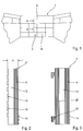
-
Figur 1 -
Figur 2Figur 1 ; -
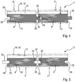
Figuren 3 und4 einen einen Schnitt durch ein zweites und ein drittes Ausführungsbeispiele eines Wandpaneels, und -
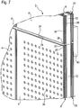
Figuren 5 bis 7 drei weitere Ausführungsbeispiele von Wandpaneelen mit nut-/federartigen Verbindungsmitteln (Fremdfeder).
-
Figure 1 a highly schematic representation of a hall end wall provided with a wall construction; -
Figure 2 a section through a first embodiment of a wall panel of a wall construction according toFigure 1 ; -
Figures 3 and4th a section through a second and a third exemplary embodiment of a wall panel, and -
Figures 5 to 7 three further exemplary embodiments of wall panels with tongue and groove-like connecting means (foreign spring).
Die Erfindung wird im Folgenden zunächst anhand einer Wandkonstruktion für eine Sporthalle oder dergleichen und danach anhand von akustisch optimierten Wandkonstruktionen erläutert. Wie bereits eingangs ausgeführt, ist die Erfindung jedoch nicht auf derartige Anwendungen beschränkt, da die erfindungsgemäßen Wandpaneele auch zum Verkleiden der Wandung von Hörsälen, Konzertsälen oder dergleichen oder aber auch als Designelement oder dergleichen nutzbar sind.The invention is explained in the following first with the aid of a wall construction for a sports hall or the like and then with the aid of acoustically optimized wall constructions. As already stated at the outset, the invention is not limited to such applications, however, since the wall panels according to the invention can also be used to clad the walls of lecture halls, concert halls or the like or as a design element or the like.
Im Unterschied zu herkömmlichen Lösungen wird die Wandkonstruktion mit der Unterkonstruktion und dem darauf befestigten Dämmelementen nicht vor Ort, auf der Baustelle gefertigt, sondern es handelt sich bei den erfindungsgemäßen Wandpaneelen um vorgefertigte Bauteile, die lediglich noch an der Wand 6 angebracht werden müssen.In contrast to conventional solutions, the wall construction with the substructure and the insulating elements attached to it is not manufactured on site, on the construction site, but the wall panels according to the invention are prefabricated components that only need to be attached to the
Wie des Weiteren in
Anstelle der Klebestreifen 14 kann auch eine Klettverbindung vorgesehen sein, von der ein Teil an der Wand 16 angebracht wird und der andere, damit in Wirkeingriff zu bringende Teil am Paneel verbleibt. Das wandseitige Klettteil (Streifen) kann mit einer Klebeschicht versehen sein, so dass es beim Ansetzen des Paneels an der Wand haftet. Anstelle einer streifenförmigen Klettverbindung kann auch eine flächige Klettverbindung oder dergleichen verwendet werden.Instead of the
Wie eingangs erläutert, zeichnet sich die erfindungsgemäße Wandkonstruktion 2 durch eine sehr geringe Aufbauhöhe H (siehe
Dieser angelieferte Sandwichaufbau, im Wesentlichen bestehend aus Oberschicht 8, der Dämpfungsschicht 12 und den Klebestreifen 14 und ggf. einer Dekorschicht 10, wird werksseitig als vorgefertigtes Paneel bereitgestellt. Vorort kann dann das Wandpaneel 4 mittels der Klebestreifen 14 oder der Klettverbindung an der Wand 6 vorfixiert werden. Eine endgültige Befestigung, die den Schritt der Vorfixierung nicht Bedarf, erfolgt bei dem in
Alternativ kann wie bereits erwähnt bei Verwendung einer Montageverklebung mit ausreichender Anfangshaftung auf die Vorfixierung verzichtet werden.Alternatively, as already mentioned, pre-fixing can be dispensed with when using assembly bonding with sufficient initial adhesion.
Alternativ zur Montageverklebung kann auch die Befestigung in herkömmlicher Weise durch Verschrauben, Nageln oder sonstige Weise erfolgen.As an alternative to the assembly gluing, the fastening can also take place in a conventional manner by screwing, nailing or other means.
Bei diesem Ausführungsbeispiel sind die Oberschicht 8 und die Dämpfungsschicht 12 auf einer Trägerplatte 20 aufgebracht, die aus einem Sperrholz oder einem anderen geeigneten Material bestehen kann. D. h., bei diesem Ausführungsbeispiel besteht die Sandwichkonstruktion aus drei Grundelementen: der Oberschicht 8, der Dämpfungsschicht 12 und der Trägerplatte 20. Zur Befestigung kann diese mit geeigneten Befestigungselementen, beispielsweise einer rückseitigen Aufhängung 22 versehen sein, die dann in entsprechende Aufnahmen an der Wand 6 eingehängt wird. Prinzipiell kann der Sandwichaufbau gemäß
Zur Verbesserung der Relativpositionierung sind die Wandpaneele 4 aller Ausführungsbeispiele - explizit nur in den
Bei den Abbildungen in
Beim Ausführungsbeispiel gemäß
Entsprechende Nut-/Federprofile sind auch an den parallel zur Zeichenebene verlaufenden Seitenflächen/Stirnkanten ausgebildet. Auf diese Weise kann ein Überzahn der Wandpaneele 4, 4' zuverlässig vermieden werden, so dass die Verletzungsgefahr für die Sportler verringert ist.Corresponding tongue and groove profiles are also formed on the side surfaces / front edges running parallel to the plane of the drawing. In this way, an overlapping of the
Bei der in
Wie eingangs erwähnt, können die Nut-/Federelemente ähnlich wie bei den Fußbodenpaneelen mit Clickverbindungen ausgeführt sein, die eine Verriegelung in der Montageebene oder Ebene der Großfläche bewirken, so dass eine Spaltenbildung, beispielsweise aufgrund von Temperaturänderungen verhindert ist.As mentioned at the beginning, the tongue and groove elements can be designed with click connections similar to the floor panels, which lock in the assembly plane or plane of the large area, so that gaps are prevented from forming, for example due to temperature changes.
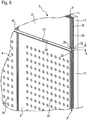
Wie in den
Die Dicke D der Oberschicht oder Sperrschicht 8 kann beispielsweise zwischen 6 und 12 mm betragen. Wie erwähnt, wird die Verwendung von Sperrholz für die Oberschicht 8 bevorzugt. Selbstverständlich können auch andere Materialien Verwendung finden. Die Nuten 26 in den Seitenflächen/Stirnflächen der Wandpaneele 4, 4' werden vorzugsweise durch Fräsen oder dergleichen ausgebildet. Entsprechendes gilt für die Federprofile 30 des Ausführungsbeispiels gemäß
In dem Fall, in dem die Wandkonstruktion zur Verkleidung eines Konzertsaals oder dergleichen dient, können die Wandpaneele mit Lochungen und/oder Schlitzen versehen sein, die im Hinblick auf die Verbesserung der Akustik ausgelegt sind. Dabei ist es durchaus vorstellbar, dass die Wandkonstruktion bei Mehrzweckhallen Verwendung findet, bei der sie sowohl als Prallwand als aber auch als Akustikwand dient. D. h., in diesem Fall ist die Konstruktion sowohl im Hinblick auf die mechanische Dämpfung/Dämmung als auch im Hinblick auf die Akustik ausgelegt.In the case in which the wall construction is used to cover a concert hall or the like, the wall panels can be provided with perforations and / or slots which are designed with a view to improving the acoustics. It is quite conceivable that the wall construction will be used in multi-purpose halls, where it serves both as a baffle wall and as an acoustic wall. In other words, in this case the construction is designed both with regard to mechanical damping / insulation and with regard to acoustics.
Ausführungsbeispiele zur akustisch vorteilhaften Verkleidung eines Konzertsaals zeigen
Bei genauerer Betrachtung ist in
Gut zu erkennen ist, dass die Fremdfeder 32 in beiden Nuten 26 bis zu deren jeweiligem Nutgrund eingetaucht ist. Da eine Tiefe der Feder 32, gemessen von Nutgrund zu Nutgrund, größer ist als eine Summe der Tiefen der Nuten 26, verbleibt zwischen den Seitenflächen 26 und 28 der Wandpaneele 4, 4' eine Fuge, in der ein Mittelabschnitt der Fremdfeder 32 sichtbar ist.It can be clearly seen that the
Gemäß
Das Ausführungsbeispiel gemäß
Prinzipiell kann anstelle der Montageverklebung auch eine hinreichende Haltekräfte gewährleistende Klettverbindung zur Fixierung verwendet werden.In principle, instead of the assembly bonding, a Velcro connection that ensures sufficient holding forces can also be used for fixing.
Prinzipiell ist es möglich - wie vorstehend erwähnt - die Montage durch eine Verschraubung durch die Sichtseite des Wandpaneels durchzuführen. Anstelle der Aufhängung 22 können selbstverständlich auch andere geeignete Montagemittel rückseitig vorgesehen werden.In principle it is possible - as mentioned above - to carry out the assembly by screwing through the visible side of the wall panel. Instead of the
Ein Vorteil der Lösung mit werkseitig vorgefertigtem Sandwichaufbau ist, dass die fertigen Wandpaneele angeliefert werden, so dass zur Montage an der Sporthallenwand nur noch ein sehr geringer Aufwand erforderlich ist.One advantage of the solution with a sandwich structure prefabricated at the factory is that the finished wall panels are delivered, so that only very little effort is required for mounting on the sports hall wall.
Prinzipiell ist es auch möglich, an den Umfangskanten der Wandpaneele 4 geeignete Nut-/Federverbindungen vorzusehen, die zusätzlich noch mit Verriegelungselementen zum Verriegeln senkrecht und parallel zur Verlegerichtung ausgeführt sein können.In principle, it is also possible to provide suitable tongue and groove connections on the peripheral edges of the
Anstelle der Sperrholzmaterialien können für die Oberschicht 8 und die Trägerplatte 20 auch andere geeignete Materialien, beispielsweise MDF/HDF-Platten oder WPC-Elemente (Wood Plastic Compound) oder dergleichen verwendet werden.Instead of the plywood materials, other suitable materials, for example MDF / HDF panels or WPC elements (Wood Plastic Compound) or the like, can also be used for the
Offenbart ist eine Wandkonstruktion und ein Verfahren zum Montieren einer derartigen Wandkonstruktion, wobei Wandpaneele mit einer Ober- und einer Dämpfungsschicht als vorgefertigte Sandwichkonstruktionen ausgeführt sind. Die Wandkonstruktion kann beispielsweise als Prallwand-, Akustik- oder Designwandkonstruktion ausgeführt sein. Dabei sind nut-/federartige Verbindungsmittel an Seitenflächen der vergleichsweise harten oder zähen Oberschichten vorgesehen, über die die Wandpaneele in einer Richtung senkrecht zur Montagefläche aneinander positionierbar sind.Disclosed is a wall construction and a method for assembling such a wall construction, wall panels with a top layer and a damping layer being designed as prefabricated sandwich constructions. The wall construction can be designed, for example, as a baffle wall, acoustic or design wall construction. Tongue / tongue-like connecting means are provided on side surfaces of the comparatively hard or tough top layers, by means of which the wall panels can be positioned on one another in a direction perpendicular to the mounting surface.
Offenbart ist auch ein Verfahren zum Montieren einer derartigen Wandkonstruktion in dem an den Seitenflächen einander benachbarter Oberschichten der Wandpaneele vorgesehene nut-/federartige Verbindungsmittel so verbunden werden, dass die Wandpaneele zumindest in Richtung senkrecht zu ihrer Großfläche aneinander sicher positioniert sind.A method for assembling such a wall construction is also disclosed in which tongue / groove-like connecting means provided on the side surfaces of adjacent upper layers of the wall panels are connected in such a way that the wall panels are securely positioned on one another at least in the direction perpendicular to their large surface.
- 11
- SporthalleGym
- 22
- WandkonstruktionWall construction
- 44th
- WandpaneelWall panel
- 66th
- StirnwandFront wall
- 88th
- OberschichtUpper class
- 1010
- DekorschichtDecorative layer
- 1212
- DämmschichtInsulation layer
- 1414th
- KlebestreifenAdhesive tape
- 1818th
- MontageverklebungAssembly bonding
- 2020th
- TrägerplatteCarrier plate
- 2222nd
- Aufhängungsuspension
- 2424
- SeitenflächeSide face
- 2626th
- NutGroove
- 2828
- SeitenflächeSide face
- 3030th
- Federfeather
- 3232
- FremdfederForeign spring
- 3434
- LochungPerforation
- 3636
- Schicht mit erster FaserorientierungLayer with first fiber orientation
- 3838
- Schicht mit zweiter FaserorientierungLayer with second fiber orientation
- 4040
- LastverteilungsschichtLoad sharing layer
Claims (13)
- Wall construction (2) for covering a wall surface of a sports facility (1), having a plurality of wall panels (4, 4'), each having a damping/insulating layer (12) which directly or indirectly supports a top layer (8, 8'), wherein, on side surfaces (24, 28) of the wall panels (4, 4'), tongue-and-groove-like connecting means (26, 32) are provided, via which the wall panels (4, 4') can be positioned against one another in a direction perpendicular to a large surface of the wall panels (4, 4'), characterised in that the tongue-and-groove-like connecting means (26, 32) are provided on the top layer (8, 8'), wherein a tongue depth of a separate tongue (32) of the tongue-and-groove-like like connecting means (26, 32) is greater than a sum of groove depths of adjacent grooves (26) with which the separate tongue (32) is engaged.
- Wall construction (2) according to claim 1, wherein positions of mutually adjacent grooves (26), in their respective top layer (8, 8') with respect to the direction perpendicular to the large surface, are the same.
- Wall construction (2) according to any of the preceding claims, wherein at least one of the separate tongues (32) of the tongue-and-groove-like connecting means (26, 32) is matched with an interference fit to at least one of the grooves with which it is engaged.
- Wall construction (2) according to any of the preceding claims, wherein at least one of the separate tongues (32) of the tongue-and-groove-like connecting means (26, 32) can be deformed in a flexurally elastic manner in the direction perpendicular to the large surface.
- Wall construction (2) according to any of the preceding claims, wherein the top layer (8, 8') has a multilayer structure.
- Wall construction (2) according to claim 5, wherein the top layer (8) consists of plywood.
- Wall construction (2) according to any of the preceding claims, wherein the damping layer (12) protrudes beyond the top layer (8, 8') on at least one of the side surfaces (24, 28).
- Wall construction (2) according to any of the preceding claims, wherein the top layer (8, 8') supports a decorative layer (10).
- Wall construction (2) according to claim 8, wherein the decorative layer (10) is a film, a CP laminate or a real wood veneer.
- Wall construction (2) according to any of the preceding claims, having a support plate (20) supporting the top layer (8, 8').
- Wall construction (2) according to claim 10, wherein the support plate (20) is thinner than the top layer (8).
- Wall construction (2) according to any of the preceding claims, wherein at least the top layer (8) of at least some (4) of the wall panels (4, 4') is slotted or provided with holes/recesses (34), in particular to improve the acoustics or an air conditioning or an appearance.
- Method for mounting a wall construction (2) according to any of the preceding claims, characterised by a step of:- connecting the tongue-and-groove-like connecting means (26, 30; 26, 32) provided on the side surfaces (24, 28) of mutually adjacent top layers (8, 8'),such that the wall panels (4, 4') are positioned against one another at least in the direction perpendicular to the large surface.
Applications Claiming Priority (3)
| Application Number | Priority Date | Filing Date | Title |
|---|---|---|---|
| DE102015112230 | 2015-07-27 | ||
| DE102015115848.5A DE102015115848A1 (en) | 2015-07-27 | 2015-09-18 | Wall construction and method of mounting |
| PCT/EP2016/067913 WO2017017144A1 (en) | 2015-07-27 | 2016-07-27 | Wall construction and mounting method |
Publications (2)
| Publication Number | Publication Date |
|---|---|
| EP3329066A1 EP3329066A1 (en) | 2018-06-06 |
| EP3329066B1 true EP3329066B1 (en) | 2020-10-28 |
Family
ID=54840225
Family Applications (1)
| Application Number | Title | Priority Date | Filing Date |
|---|---|---|---|
| EP16751520.4A Active EP3329066B1 (en) | 2015-07-27 | 2016-07-27 | Wall construction and mounting method |
Country Status (3)
| Country | Link |
|---|---|
| EP (1) | EP3329066B1 (en) |
| DE (2) | DE202015105688U1 (en) |
| WO (1) | WO2017017144A1 (en) |
Families Citing this family (1)
| Publication number | Priority date | Publication date | Assignee | Title |
|---|---|---|---|---|
| DE202018100145U1 (en) | 2017-08-17 | 2018-03-05 | Hamberger Industriewerke Gmbh | Wall element for a wall or ceiling covering |
Citations (2)
| Publication number | Priority date | Publication date | Assignee | Title |
|---|---|---|---|---|
| FR2832470A1 (en) * | 2001-11-21 | 2003-05-23 | Grosfillex Sarl | Profiled strip for wall cladding has visible face with male and female connecting formations on opposing edges |
| WO2007085260A1 (en) * | 2006-01-26 | 2007-08-02 | Rockwool International A/S | Sandwich element |
Family Cites Families (15)
| Publication number | Priority date | Publication date | Assignee | Title |
|---|---|---|---|---|
| DE1946156U (en) * | 1966-07-01 | 1966-09-15 | Josef Juengling | CEILING PANEL. |
| DE7043552U (en) * | 1970-11-20 | 1971-03-18 | Papierfab Gmbh | PLATE FOR A WALL CLADDING WITH WOOD PANELING. |
| GB1379932A (en) * | 1972-01-19 | 1975-01-08 | United States Gypsum Co | Dual adhesive construction unit and method |
| DE7638003U1 (en) * | 1976-12-04 | 1977-03-24 | Dynamit Nobel Ag, 5210 Troisdorf | PLATE OR RAIL-SHAPED COVERING |
| DE8119591U1 (en) * | 1981-07-04 | 1981-11-12 | Bock, Klaus-Peter, 3250 Hameln 1 | THERMAL INSULATING PANEL |
| DE8634785U1 (en) | 1986-12-29 | 1988-01-28 | Fischer, Alfred, 8940 Memmingen | Impact wall panel |
| DE3739313A1 (en) * | 1987-11-20 | 1989-06-08 | Pape Hans | Use of a derived-timber-product panel with covering layer as a sound-absorbing wall or ceiling cladding, and process for producing such a derived-timber-product panel |
| JP2848424B2 (en) * | 1992-03-04 | 1999-01-20 | 永大産業株式会社 | Combination decorative board |
| JPH05302376A (en) * | 1992-04-23 | 1993-11-16 | Sankyo U B Kk | Laminated panel |
| JPH08120878A (en) * | 1994-10-25 | 1996-05-14 | Yamazaki Mokuzaiten:Kk | Interior finishing material for building |
| JPH11131622A (en) * | 1997-10-31 | 1999-05-18 | Daiken Trade & Ind Co Ltd | Sound insulating wood building plate |
| DE29815801U1 (en) | 1998-09-02 | 1999-02-04 | Scheying, Heinz Friedrich, 71254 Ditzingen | Cruciate ligament baffle |
| AT3972U1 (en) | 1999-09-03 | 2000-11-27 | Diaplan Liegenschaftsverwaltun | WALL COVERING |
| DE10257367A1 (en) | 2002-12-09 | 2004-07-22 | Mawi-Prallschutz Gmbh | Wall padding, for a gymnasium or kindergarten and the like, has a polyester foam padding layer and a polyester outer fabric for protection against injury and increased flammability resistance |
| DE202013104022U1 (en) * | 2013-09-06 | 2013-10-04 | Meifu Liu | renovation plate |
-
2015
- 2015-09-18 DE DE202015105688.5U patent/DE202015105688U1/en active Active
- 2015-09-18 DE DE102015115848.5A patent/DE102015115848A1/en active Pending
-
2016
- 2016-07-27 EP EP16751520.4A patent/EP3329066B1/en active Active
- 2016-07-27 WO PCT/EP2016/067913 patent/WO2017017144A1/en active Application Filing
Patent Citations (2)
| Publication number | Priority date | Publication date | Assignee | Title |
|---|---|---|---|---|
| FR2832470A1 (en) * | 2001-11-21 | 2003-05-23 | Grosfillex Sarl | Profiled strip for wall cladding has visible face with male and female connecting formations on opposing edges |
| WO2007085260A1 (en) * | 2006-01-26 | 2007-08-02 | Rockwool International A/S | Sandwich element |
Also Published As
| Publication number | Publication date |
|---|---|
| DE202015105688U1 (en) | 2015-11-24 |
| EP3329066A1 (en) | 2018-06-06 |
| DE102015115848A1 (en) | 2017-02-02 |
| WO2017017144A1 (en) | 2017-02-02 |
Similar Documents
| Publication | Publication Date | Title |
|---|---|---|
| EP3112545B1 (en) | Acoustic panel | |
| WO2017017139A1 (en) | Panel | |
| EP2039842A2 (en) | Dry construction system | |
| EP3329066B1 (en) | Wall construction and mounting method | |
| DE202016103049U1 (en) | paneling | |
| DE102012221746A1 (en) | Wall heating element i.e. gypsum fiber board, has grooves arranged in front side or back of plate element for retaining heating pipeline and valve arranged at rear profile with undercut for engaging with fixed wall corresponding to hooks | |
| DE102011121377B4 (en) | Cladding panel for installation in a soffit or a fall | |
| DE60319910T3 (en) | Acoustic system with elastic and damping connection for the construction of partitions, panels and suspended ceilings | |
| DE102011012023A1 (en) | Connection element for connecting e.g. floor linings in indoor area, has fastening sections formed in adjacent components for engagement in recesses closed to side surfaces and adapted to cross-sections of fastening sections | |
| DE19815202A1 (en) | Insulation board for use on exterior facades of houses | |
| DE102005001184A1 (en) | Connector for attaching parquet workpiece to base has dovetail joint with tenon engaging grooves in adjacent workpiece | |
| DE10304358A1 (en) | Partition element for production of space partition, consists of disk cuts that serve as a acoustic boards to enable the element to absorb sound | |
| AT505324B1 (en) | WOODEN BUILDING ELEMENT AND WALL ELEMENT MADE THEREFROM | |
| EP1867796B1 (en) | Composite boards for interior work | |
| WO2006002818A1 (en) | Surface coating | |
| EP3670783B1 (en) | Mounting clip for floating mounting of wall and ceiling panels | |
| DE202017102839U1 (en) | Three-dimensional wall or ceiling paneling | |
| DE19725040C2 (en) | External wall for residential buildings | |
| DE202004006140U1 (en) | Panels for two-layer parquet | |
| EP3202993B1 (en) | Wooden ceiling element | |
| EP1916358A2 (en) | Use of foils or panels made of rubber polyurethane composite material for noise and vibration isolation | |
| EP1726735A1 (en) | Wall covering system | |
| BE1025589B1 (en) | Thermally insulated wall and method for its manufacture | |
| DE20000540U1 (en) | Vario block for ETICS facades | |
| DE202015100079U1 (en) | Quick-build sandwich wall element system for forming a removable wall |
Legal Events
| Date | Code | Title | Description |
|---|---|---|---|
| STAA | Information on the status of an ep patent application or granted ep patent |
Free format text: STATUS: THE INTERNATIONAL PUBLICATION HAS BEEN MADE |
|
| PUAI | Public reference made under article 153(3) epc to a published international application that has entered the european phase |
Free format text: ORIGINAL CODE: 0009012 |
|
| STAA | Information on the status of an ep patent application or granted ep patent |
Free format text: STATUS: REQUEST FOR EXAMINATION WAS MADE |
|
| 17P | Request for examination filed |
Effective date: 20180226 |
|
| AK | Designated contracting states |
Kind code of ref document: A1 Designated state(s): AL AT BE BG CH CY CZ DE DK EE ES FI FR GB GR HR HU IE IS IT LI LT LU LV MC MK MT NL NO PL PT RO RS SE SI SK SM TR |
|
| AX | Request for extension of the european patent |
Extension state: BA ME |
|
| STAA | Information on the status of an ep patent application or granted ep patent |
Free format text: STATUS: EXAMINATION IS IN PROGRESS |
|
| 17Q | First examination report despatched |
Effective date: 20180927 |
|
| DAV | Request for validation of the european patent (deleted) | ||
| DAX | Request for extension of the european patent (deleted) | ||
| REG | Reference to a national code |
Ref country code: DE Ref legal event code: R079 Ref document number: 502016011559 Country of ref document: DE Free format text: PREVIOUS MAIN CLASS: E04F0013080000 Ipc: E04F0013075000 |
|
| GRAP | Despatch of communication of intention to grant a patent |
Free format text: ORIGINAL CODE: EPIDOSNIGR1 |
|
| STAA | Information on the status of an ep patent application or granted ep patent |
Free format text: STATUS: GRANT OF PATENT IS INTENDED |
|
| RIC1 | Information provided on ipc code assigned before grant |
Ipc: E04F 13/08 20060101ALI20200428BHEP Ipc: E04F 13/075 20060101AFI20200428BHEP Ipc: E04F 13/10 20060101ALI20200428BHEP Ipc: E04B 1/86 20060101ALI20200428BHEP Ipc: E04B 1/74 20060101ALI20200428BHEP |
|
| INTG | Intention to grant announced |
Effective date: 20200515 |
|
| GRAS | Grant fee paid |
Free format text: ORIGINAL CODE: EPIDOSNIGR3 |
|
| GRAA | (expected) grant |
Free format text: ORIGINAL CODE: 0009210 |
|
| STAA | Information on the status of an ep patent application or granted ep patent |
Free format text: STATUS: THE PATENT HAS BEEN GRANTED |
|
| AK | Designated contracting states |
Kind code of ref document: B1 Designated state(s): AL AT BE BG CH CY CZ DE DK EE ES FI FR GB GR HR HU IE IS IT LI LT LU LV MC MK MT NL NO PL PT RO RS SE SI SK SM TR |
|
| REG | Reference to a national code |
Ref country code: GB Ref legal event code: FG4D Free format text: NOT ENGLISH |
|
| REG | Reference to a national code |
Ref country code: CH Ref legal event code: EP |
|
| REG | Reference to a national code |
Ref country code: DE Ref legal event code: R096 Ref document number: 502016011559 Country of ref document: DE |
|
| REG | Reference to a national code |
Ref country code: AT Ref legal event code: REF Ref document number: 1328382 Country of ref document: AT Kind code of ref document: T Effective date: 20201115 |
|
| REG | Reference to a national code |
Ref country code: IE Ref legal event code: FG4D Free format text: LANGUAGE OF EP DOCUMENT: GERMAN |
|
| REG | Reference to a national code |
Ref country code: NL Ref legal event code: MP Effective date: 20201028 |
|
| PG25 | Lapsed in a contracting state [announced via postgrant information from national office to epo] |
Ref country code: GR Free format text: LAPSE BECAUSE OF FAILURE TO SUBMIT A TRANSLATION OF THE DESCRIPTION OR TO PAY THE FEE WITHIN THE PRESCRIBED TIME-LIMIT Effective date: 20210129 Ref country code: FI Free format text: LAPSE BECAUSE OF FAILURE TO SUBMIT A TRANSLATION OF THE DESCRIPTION OR TO PAY THE FEE WITHIN THE PRESCRIBED TIME-LIMIT Effective date: 20201028 Ref country code: RS Free format text: LAPSE BECAUSE OF FAILURE TO SUBMIT A TRANSLATION OF THE DESCRIPTION OR TO PAY THE FEE WITHIN THE PRESCRIBED TIME-LIMIT Effective date: 20201028 Ref country code: PT Free format text: LAPSE BECAUSE OF FAILURE TO SUBMIT A TRANSLATION OF THE DESCRIPTION OR TO PAY THE FEE WITHIN THE PRESCRIBED TIME-LIMIT Effective date: 20210301 Ref country code: NO Free format text: LAPSE BECAUSE OF FAILURE TO SUBMIT A TRANSLATION OF THE DESCRIPTION OR TO PAY THE FEE WITHIN THE PRESCRIBED TIME-LIMIT Effective date: 20210128 |
|
| REG | Reference to a national code |
Ref country code: LT Ref legal event code: MG4D |
|
| PG25 | Lapsed in a contracting state [announced via postgrant information from national office to epo] |
Ref country code: ES Free format text: LAPSE BECAUSE OF FAILURE TO SUBMIT A TRANSLATION OF THE DESCRIPTION OR TO PAY THE FEE WITHIN THE PRESCRIBED TIME-LIMIT Effective date: 20201028 Ref country code: PL Free format text: LAPSE BECAUSE OF FAILURE TO SUBMIT A TRANSLATION OF THE DESCRIPTION OR TO PAY THE FEE WITHIN THE PRESCRIBED TIME-LIMIT Effective date: 20201028 Ref country code: IS Free format text: LAPSE BECAUSE OF FAILURE TO SUBMIT A TRANSLATION OF THE DESCRIPTION OR TO PAY THE FEE WITHIN THE PRESCRIBED TIME-LIMIT Effective date: 20210228 Ref country code: LV Free format text: LAPSE BECAUSE OF FAILURE TO SUBMIT A TRANSLATION OF THE DESCRIPTION OR TO PAY THE FEE WITHIN THE PRESCRIBED TIME-LIMIT Effective date: 20201028 Ref country code: BG Free format text: LAPSE BECAUSE OF FAILURE TO SUBMIT A TRANSLATION OF THE DESCRIPTION OR TO PAY THE FEE WITHIN THE PRESCRIBED TIME-LIMIT Effective date: 20210128 Ref country code: SE Free format text: LAPSE BECAUSE OF FAILURE TO SUBMIT A TRANSLATION OF THE DESCRIPTION OR TO PAY THE FEE WITHIN THE PRESCRIBED TIME-LIMIT Effective date: 20201028 |
|
| PG25 | Lapsed in a contracting state [announced via postgrant information from national office to epo] |
Ref country code: HR Free format text: LAPSE BECAUSE OF FAILURE TO SUBMIT A TRANSLATION OF THE DESCRIPTION OR TO PAY THE FEE WITHIN THE PRESCRIBED TIME-LIMIT Effective date: 20201028 Ref country code: NL Free format text: LAPSE BECAUSE OF FAILURE TO SUBMIT A TRANSLATION OF THE DESCRIPTION OR TO PAY THE FEE WITHIN THE PRESCRIBED TIME-LIMIT Effective date: 20201028 |
|
| REG | Reference to a national code |
Ref country code: DE Ref legal event code: R097 Ref document number: 502016011559 Country of ref document: DE |
|
| PG25 | Lapsed in a contracting state [announced via postgrant information from national office to epo] |
Ref country code: LT Free format text: LAPSE BECAUSE OF FAILURE TO SUBMIT A TRANSLATION OF THE DESCRIPTION OR TO PAY THE FEE WITHIN THE PRESCRIBED TIME-LIMIT Effective date: 20201028 Ref country code: SM Free format text: LAPSE BECAUSE OF FAILURE TO SUBMIT A TRANSLATION OF THE DESCRIPTION OR TO PAY THE FEE WITHIN THE PRESCRIBED TIME-LIMIT Effective date: 20201028 Ref country code: EE Free format text: LAPSE BECAUSE OF FAILURE TO SUBMIT A TRANSLATION OF THE DESCRIPTION OR TO PAY THE FEE WITHIN THE PRESCRIBED TIME-LIMIT Effective date: 20201028 Ref country code: RO Free format text: LAPSE BECAUSE OF FAILURE TO SUBMIT A TRANSLATION OF THE DESCRIPTION OR TO PAY THE FEE WITHIN THE PRESCRIBED TIME-LIMIT Effective date: 20201028 Ref country code: SK Free format text: LAPSE BECAUSE OF FAILURE TO SUBMIT A TRANSLATION OF THE DESCRIPTION OR TO PAY THE FEE WITHIN THE PRESCRIBED TIME-LIMIT Effective date: 20201028 |
|
| PG25 | Lapsed in a contracting state [announced via postgrant information from national office to epo] |
Ref country code: DK Free format text: LAPSE BECAUSE OF FAILURE TO SUBMIT A TRANSLATION OF THE DESCRIPTION OR TO PAY THE FEE WITHIN THE PRESCRIBED TIME-LIMIT Effective date: 20201028 |
|
| PLBE | No opposition filed within time limit |
Free format text: ORIGINAL CODE: 0009261 |
|
| STAA | Information on the status of an ep patent application or granted ep patent |
Free format text: STATUS: NO OPPOSITION FILED WITHIN TIME LIMIT |
|
| 26N | No opposition filed |
Effective date: 20210729 |
|
| PG25 | Lapsed in a contracting state [announced via postgrant information from national office to epo] |
Ref country code: IT Free format text: LAPSE BECAUSE OF FAILURE TO SUBMIT A TRANSLATION OF THE DESCRIPTION OR TO PAY THE FEE WITHIN THE PRESCRIBED TIME-LIMIT Effective date: 20201028 Ref country code: AL Free format text: LAPSE BECAUSE OF FAILURE TO SUBMIT A TRANSLATION OF THE DESCRIPTION OR TO PAY THE FEE WITHIN THE PRESCRIBED TIME-LIMIT Effective date: 20201028 |
|
| PG25 | Lapsed in a contracting state [announced via postgrant information from national office to epo] |
Ref country code: SI Free format text: LAPSE BECAUSE OF FAILURE TO SUBMIT A TRANSLATION OF THE DESCRIPTION OR TO PAY THE FEE WITHIN THE PRESCRIBED TIME-LIMIT Effective date: 20201028 |
|
| REG | Reference to a national code |
Ref country code: CH Ref legal event code: PL |
|
| GBPC | Gb: european patent ceased through non-payment of renewal fee |
Effective date: 20210727 |
|
| PG25 | Lapsed in a contracting state [announced via postgrant information from national office to epo] |
Ref country code: MC Free format text: LAPSE BECAUSE OF FAILURE TO SUBMIT A TRANSLATION OF THE DESCRIPTION OR TO PAY THE FEE WITHIN THE PRESCRIBED TIME-LIMIT Effective date: 20201028 |
|
| REG | Reference to a national code |
Ref country code: BE Ref legal event code: MM Effective date: 20210731 |
|
| PG25 | Lapsed in a contracting state [announced via postgrant information from national office to epo] |
Ref country code: LI Free format text: LAPSE BECAUSE OF NON-PAYMENT OF DUE FEES Effective date: 20210731 Ref country code: GB Free format text: LAPSE BECAUSE OF NON-PAYMENT OF DUE FEES Effective date: 20210727 Ref country code: CH Free format text: LAPSE BECAUSE OF NON-PAYMENT OF DUE FEES Effective date: 20210731 |
|
| PG25 | Lapsed in a contracting state [announced via postgrant information from national office to epo] |
Ref country code: IS Free format text: LAPSE BECAUSE OF FAILURE TO SUBMIT A TRANSLATION OF THE DESCRIPTION OR TO PAY THE FEE WITHIN THE PRESCRIBED TIME-LIMIT Effective date: 20210228 Ref country code: FR Free format text: LAPSE BECAUSE OF NON-PAYMENT OF DUE FEES Effective date: 20210731 Ref country code: LU Free format text: LAPSE BECAUSE OF NON-PAYMENT OF DUE FEES Effective date: 20210727 |
|
| PG25 | Lapsed in a contracting state [announced via postgrant information from national office to epo] |
Ref country code: IE Free format text: LAPSE BECAUSE OF NON-PAYMENT OF DUE FEES Effective date: 20210727 Ref country code: BE Free format text: LAPSE BECAUSE OF NON-PAYMENT OF DUE FEES Effective date: 20210731 |
|
| PG25 | Lapsed in a contracting state [announced via postgrant information from national office to epo] |
Ref country code: HU Free format text: LAPSE BECAUSE OF FAILURE TO SUBMIT A TRANSLATION OF THE DESCRIPTION OR TO PAY THE FEE WITHIN THE PRESCRIBED TIME-LIMIT; INVALID AB INITIO Effective date: 20160727 |
|
| PG25 | Lapsed in a contracting state [announced via postgrant information from national office to epo] |
Ref country code: CY Free format text: LAPSE BECAUSE OF FAILURE TO SUBMIT A TRANSLATION OF THE DESCRIPTION OR TO PAY THE FEE WITHIN THE PRESCRIBED TIME-LIMIT Effective date: 20201028 |
|
| PGFP | Annual fee paid to national office [announced via postgrant information from national office to epo] |
Ref country code: CZ Payment date: 20230717 Year of fee payment: 8 Ref country code: AT Payment date: 20230718 Year of fee payment: 8 |
|
| PGFP | Annual fee paid to national office [announced via postgrant information from national office to epo] |
Ref country code: DE Payment date: 20230614 Year of fee payment: 8 |
|
| PG25 | Lapsed in a contracting state [announced via postgrant information from national office to epo] |
Ref country code: MK Free format text: LAPSE BECAUSE OF FAILURE TO SUBMIT A TRANSLATION OF THE DESCRIPTION OR TO PAY THE FEE WITHIN THE PRESCRIBED TIME-LIMIT Effective date: 20201028 |
|
| PG25 | Lapsed in a contracting state [announced via postgrant information from national office to epo] |
Ref country code: TR Free format text: LAPSE BECAUSE OF FAILURE TO SUBMIT A TRANSLATION OF THE DESCRIPTION OR TO PAY THE FEE WITHIN THE PRESCRIBED TIME-LIMIT Effective date: 20201028 |