EP3328443B1 - Systeme und verfahren zur erkennung von flüssigkeitslecks mit einem berührungslosen, optischen sensor - Google Patents
Systeme und verfahren zur erkennung von flüssigkeitslecks mit einem berührungslosen, optischen sensor Download PDFInfo
- Publication number
- EP3328443B1 EP3328443B1 EP16754012.9A EP16754012A EP3328443B1 EP 3328443 B1 EP3328443 B1 EP 3328443B1 EP 16754012 A EP16754012 A EP 16754012A EP 3328443 B1 EP3328443 B1 EP 3328443B1
- Authority
- EP
- European Patent Office
- Prior art keywords
- biological fluid
- fluid
- overflow reservoir
- container
- irradiation device
- Prior art date
- Legal status (The legal status is an assumption and is not a legal conclusion. Google has not performed a legal analysis and makes no representation as to the accuracy of the status listed.)
- Active
Links
Images


Classifications
-
- C—CHEMISTRY; METALLURGY
- C12—BIOCHEMISTRY; BEER; SPIRITS; WINE; VINEGAR; MICROBIOLOGY; ENZYMOLOGY; MUTATION OR GENETIC ENGINEERING
- C12N—MICROORGANISMS OR ENZYMES; COMPOSITIONS THEREOF; PROPAGATING, PRESERVING, OR MAINTAINING MICROORGANISMS; MUTATION OR GENETIC ENGINEERING; CULTURE MEDIA
- C12N5/00—Undifferentiated human, animal or plant cells, e.g. cell lines; Tissues; Cultivation or maintenance thereof; Culture media therefor
- C12N5/06—Animal cells or tissues; Human cells or tissues
- C12N5/0602—Vertebrate cells
- C12N5/0634—Cells from the blood or the immune system
- C12N5/0641—Erythrocytes
-
- A—HUMAN NECESSITIES
- A61—MEDICAL OR VETERINARY SCIENCE; HYGIENE
- A61M—DEVICES FOR INTRODUCING MEDIA INTO, OR ONTO, THE BODY; DEVICES FOR TRANSDUCING BODY MEDIA OR FOR TAKING MEDIA FROM THE BODY; DEVICES FOR PRODUCING OR ENDING SLEEP OR STUPOR
- A61M1/00—Suction or pumping devices for medical purposes; Devices for carrying-off, for treatment of, or for carrying-over, body-liquids; Drainage systems
- A61M1/36—Other treatment of blood in a by-pass of the natural circulatory system, e.g. temperature adaptation, irradiation ; Extra-corporeal blood circuits
- A61M1/3681—Other treatment of blood in a by-pass of the natural circulatory system, e.g. temperature adaptation, irradiation ; Extra-corporeal blood circuits by irradiation
-
- A—HUMAN NECESSITIES
- A61—MEDICAL OR VETERINARY SCIENCE; HYGIENE
- A61L—METHODS OR APPARATUS FOR STERILISING MATERIALS OR OBJECTS IN GENERAL; DISINFECTION, STERILISATION OR DEODORISATION OF AIR; CHEMICAL ASPECTS OF BANDAGES, DRESSINGS, ABSORBENT PADS OR SURGICAL ARTICLES; MATERIALS FOR BANDAGES, DRESSINGS, ABSORBENT PADS OR SURGICAL ARTICLES
- A61L2/00—Disinfection or sterilisation of materials or objects, in general; Accessories therefor
- A61L2/02—Disinfection or sterilisation of materials or objects, in general; Accessories therefor using physical processes
- A61L2/08—Radiation
- A61L2/10—Ultraviolet [UV] radiation
-
- A—HUMAN NECESSITIES
- A61—MEDICAL OR VETERINARY SCIENCE; HYGIENE
- A61M—DEVICES FOR INTRODUCING MEDIA INTO, OR ONTO, THE BODY; DEVICES FOR TRANSDUCING BODY MEDIA OR FOR TAKING MEDIA FROM THE BODY; DEVICES FOR PRODUCING OR ENDING SLEEP OR STUPOR
- A61M1/00—Suction or pumping devices for medical purposes; Devices for carrying-off, for treatment of, or for carrying-over, body-liquids; Drainage systems
- A61M1/02—Blood transfusion apparatus
- A61M1/0209—Multiple bag systems for separating or storing blood components
-
- A—HUMAN NECESSITIES
- A61—MEDICAL OR VETERINARY SCIENCE; HYGIENE
- A61M—DEVICES FOR INTRODUCING MEDIA INTO, OR ONTO, THE BODY; DEVICES FOR TRANSDUCING BODY MEDIA OR FOR TAKING MEDIA FROM THE BODY; DEVICES FOR PRODUCING OR ENDING SLEEP OR STUPOR
- A61M1/00—Suction or pumping devices for medical purposes; Devices for carrying-off, for treatment of, or for carrying-over, body-liquids; Drainage systems
- A61M1/36—Other treatment of blood in a by-pass of the natural circulatory system, e.g. temperature adaptation, irradiation ; Extra-corporeal blood circuits
- A61M1/3621—Extra-corporeal blood circuits
- A61M1/3622—Extra-corporeal blood circuits with a cassette forming partially or totally the blood circuit
-
- A—HUMAN NECESSITIES
- A61—MEDICAL OR VETERINARY SCIENCE; HYGIENE
- A61M—DEVICES FOR INTRODUCING MEDIA INTO, OR ONTO, THE BODY; DEVICES FOR TRANSDUCING BODY MEDIA OR FOR TAKING MEDIA FROM THE BODY; DEVICES FOR PRODUCING OR ENDING SLEEP OR STUPOR
- A61M1/00—Suction or pumping devices for medical purposes; Devices for carrying-off, for treatment of, or for carrying-over, body-liquids; Drainage systems
- A61M1/36—Other treatment of blood in a by-pass of the natural circulatory system, e.g. temperature adaptation, irradiation ; Extra-corporeal blood circuits
- A61M1/3681—Other treatment of blood in a by-pass of the natural circulatory system, e.g. temperature adaptation, irradiation ; Extra-corporeal blood circuits by irradiation
- A61M1/3683—Other treatment of blood in a by-pass of the natural circulatory system, e.g. temperature adaptation, irradiation ; Extra-corporeal blood circuits by irradiation using photoactive agents
-
- A—HUMAN NECESSITIES
- A61—MEDICAL OR VETERINARY SCIENCE; HYGIENE
- A61M—DEVICES FOR INTRODUCING MEDIA INTO, OR ONTO, THE BODY; DEVICES FOR TRANSDUCING BODY MEDIA OR FOR TAKING MEDIA FROM THE BODY; DEVICES FOR PRODUCING OR ENDING SLEEP OR STUPOR
- A61M1/00—Suction or pumping devices for medical purposes; Devices for carrying-off, for treatment of, or for carrying-over, body-liquids; Drainage systems
- A61M1/36—Other treatment of blood in a by-pass of the natural circulatory system, e.g. temperature adaptation, irradiation ; Extra-corporeal blood circuits
- A61M1/3693—Other treatment of blood in a by-pass of the natural circulatory system, e.g. temperature adaptation, irradiation ; Extra-corporeal blood circuits using separation based on different densities of components, e.g. centrifuging
- A61M1/3696—Other treatment of blood in a by-pass of the natural circulatory system, e.g. temperature adaptation, irradiation ; Extra-corporeal blood circuits using separation based on different densities of components, e.g. centrifuging with means for adding or withdrawing liquid substances during the centrifugation, e.g. continuous centrifugation
-
- C—CHEMISTRY; METALLURGY
- C12—BIOCHEMISTRY; BEER; SPIRITS; WINE; VINEGAR; MICROBIOLOGY; ENZYMOLOGY; MUTATION OR GENETIC ENGINEERING
- C12M—APPARATUS FOR ENZYMOLOGY OR MICROBIOLOGY; APPARATUS FOR CULTURING MICROORGANISMS FOR PRODUCING BIOMASS, FOR GROWING CELLS OR FOR OBTAINING FERMENTATION OR METABOLIC PRODUCTS, i.e. BIOREACTORS OR FERMENTERS
- C12M37/00—Means for sterilizing, maintaining sterile conditions or avoiding chemical or biological contamination
-
- C—CHEMISTRY; METALLURGY
- C12—BIOCHEMISTRY; BEER; SPIRITS; WINE; VINEGAR; MICROBIOLOGY; ENZYMOLOGY; MUTATION OR GENETIC ENGINEERING
- C12M—APPARATUS FOR ENZYMOLOGY OR MICROBIOLOGY; APPARATUS FOR CULTURING MICROORGANISMS FOR PRODUCING BIOMASS, FOR GROWING CELLS OR FOR OBTAINING FERMENTATION OR METABOLIC PRODUCTS, i.e. BIOREACTORS OR FERMENTERS
- C12M41/00—Means for regulation, monitoring, measurement or control, e.g. flow regulation
- C12M41/48—Automatic or computerized control
-
- A—HUMAN NECESSITIES
- A61—MEDICAL OR VETERINARY SCIENCE; HYGIENE
- A61L—METHODS OR APPARATUS FOR STERILISING MATERIALS OR OBJECTS IN GENERAL; DISINFECTION, STERILISATION OR DEODORISATION OF AIR; CHEMICAL ASPECTS OF BANDAGES, DRESSINGS, ABSORBENT PADS OR SURGICAL ARTICLES; MATERIALS FOR BANDAGES, DRESSINGS, ABSORBENT PADS OR SURGICAL ARTICLES
- A61L2103/00—Materials or objects being the target of disinfection or sterilisation
- A61L2103/05—Living organisms or biological materials
- A61L2103/09—Blood or products thereof
-
- A—HUMAN NECESSITIES
- A61—MEDICAL OR VETERINARY SCIENCE; HYGIENE
- A61L—METHODS OR APPARATUS FOR STERILISING MATERIALS OR OBJECTS IN GENERAL; DISINFECTION, STERILISATION OR DEODORISATION OF AIR; CHEMICAL ASPECTS OF BANDAGES, DRESSINGS, ABSORBENT PADS OR SURGICAL ARTICLES; MATERIALS FOR BANDAGES, DRESSINGS, ABSORBENT PADS OR SURGICAL ARTICLES
- A61L2202/00—Aspects relating to methods or apparatus for disinfecting or sterilising materials or objects
- A61L2202/10—Apparatus features
- A61L2202/14—Means for controlling sterilisation processes, data processing, presentation and storage means, e.g. sensors, controllers, programs
-
- A—HUMAN NECESSITIES
- A61—MEDICAL OR VETERINARY SCIENCE; HYGIENE
- A61M—DEVICES FOR INTRODUCING MEDIA INTO, OR ONTO, THE BODY; DEVICES FOR TRANSDUCING BODY MEDIA OR FOR TAKING MEDIA FROM THE BODY; DEVICES FOR PRODUCING OR ENDING SLEEP OR STUPOR
- A61M2205/00—General characteristics of the apparatus
- A61M2205/05—General characteristics of the apparatus combined with other kinds of therapy
- A61M2205/051—General characteristics of the apparatus combined with other kinds of therapy with radiation therapy
-
- A—HUMAN NECESSITIES
- A61—MEDICAL OR VETERINARY SCIENCE; HYGIENE
- A61M—DEVICES FOR INTRODUCING MEDIA INTO, OR ONTO, THE BODY; DEVICES FOR TRANSDUCING BODY MEDIA OR FOR TAKING MEDIA FROM THE BODY; DEVICES FOR PRODUCING OR ENDING SLEEP OR STUPOR
- A61M2205/00—General characteristics of the apparatus
- A61M2205/12—General characteristics of the apparatus with interchangeable cassettes forming partially or totally the fluid circuit
-
- A—HUMAN NECESSITIES
- A61—MEDICAL OR VETERINARY SCIENCE; HYGIENE
- A61M—DEVICES FOR INTRODUCING MEDIA INTO, OR ONTO, THE BODY; DEVICES FOR TRANSDUCING BODY MEDIA OR FOR TAKING MEDIA FROM THE BODY; DEVICES FOR PRODUCING OR ENDING SLEEP OR STUPOR
- A61M2205/00—General characteristics of the apparatus
- A61M2205/15—Detection of leaks
-
- A—HUMAN NECESSITIES
- A61—MEDICAL OR VETERINARY SCIENCE; HYGIENE
- A61M—DEVICES FOR INTRODUCING MEDIA INTO, OR ONTO, THE BODY; DEVICES FOR TRANSDUCING BODY MEDIA OR FOR TAKING MEDIA FROM THE BODY; DEVICES FOR PRODUCING OR ENDING SLEEP OR STUPOR
- A61M2205/00—General characteristics of the apparatus
- A61M2205/33—Controlling, regulating or measuring
- A61M2205/3306—Optical measuring means
Definitions
- This patent relates to devices, methods and systems for processing and treating biological fluids, such as blood and blood components. More particularly, the patent relates to devices, methods and systems involving irradiation of biological fluids, such as blood and blood components, in a container disposed in a treatment chamber.
- biological fluid refers to any fluid that is found in or that may be introduced into the body including, but not limited to, blood and blood products.
- blood product refers to whole blood or a component of whole blood such as red blood cells, white blood cells, platelets, plasma or a combination of one or more of such components that have been separated from whole blood.
- an irradiation device may be used in the treatment of a blood product that has been combined with a photochemical agent for activation when subjected to light.
- a photochemical agent for activation when subjected to light.
- photochemical agents are used, for example, in the inactivation of viruses, bacteria, and other contaminants (collectively referred to herein as "pathogens").
- Photochemical agents are also used in the treatment of mononuclear cells, such as white blood cells.
- the activated agent inactivates pathogens that may be present in a blood product.
- the activated agent targets the mononuclear cell itself as part of a treatment of a disease or a side effect of a mononuclear cell therapy.
- the biological fluid to be treated is introduced into a fluid treatment chamber within the irradiation device in flexible, plastic, sterilizable, translucent, biologically compatible containers.
- the containers may be integrally connected to other containers and plastic tubing useful in the processing of the biological fluid both before and after the treatment provided by the irradiation device.
- the device includes a fluid carrying drawer with a central cavity to allow for placement of a container-carrying tray.
- the tray is described as having a volume sufficient to hold at least the entire volume of biological fluid contained within the containers so as to minimize the risk that, in the event of container leakage, liquid will overflow and contact the electrical and mechanical components of irradiation device, even during agitation.
- WO2009115774 discloses a water dispensing apparatus with used to fill a user's water bottle, with a light source in the form of UV light emitting diodes used to provide UV disinfection to prevent cross contamination.
- an irradiation device comprises a fluid treatment chamber configured to receive a biological fluid container, the fluid treatment chamber having opposing first and second sides, at least one light source disposed adjacent at least one of the first and second sides of the fluid treatment chamber, and an overflow reservoir in fluid communication with the fluid treatment chamber to receive fluid leaking from the biological fluid container.
- the irradiation device further comprises a non-contact sensor disposed adjacent the overflow reservoir configured to generate a signal according to leaked fluid in the overflow reservoir, an indicator, and a controller coupled to the at least one light source, the non-contact sensor and the indicator, the controller configured to activate the indicator upon receipt of the signal from the sensor and to deactivate the at least one light source subsequent to receipt of the signal from the sensor.
- a method of controlling an irradiation device comprises Illuminating a biological fluid container in a fluid treatment chamber, sensing biological fluid from the fluid container in overflow reservoir in fluid communication with the fluid treatment chamber using a non-contact sensor, activating an indicator after sensing the biological fluid in the overflow reservoir, and deactivating illumination of the biological fluid container subsequent to sensing the biological fluid in the overflow reservoir.
- a system comprises a cell separator configured to direct a biological fluid into a biological fluid container and an irradiation device.
- the irradiation device comprises a fluid treatment chamber configured to receive the biological fluid container, the fluid treatment chamber having opposing first and second sides, at least one light source disposed adjacent at least one of the first and second sides of the fluid treatment chamber, and an overflow reservoir in fluid communication with the fluid treatment chamber to receive fluid leaking from the biological fluid container.
- the irradiation device further comprises a non-contact sensor disposed adjacent the overflow reservoir configured to generate a signal according to leaked fluid in the overflow reservoir, an indicator, and a controller coupled to the at least one light source, the non-contact sensor and the indicator, the controller configured to activate the indicator upon receipt of the signal from the sensor and to deactivate the at least one light source subsequent to receipt of the signal from the sensor.
- an irradiation device 10 includes a fluid treatment chamber 12 configured to receive a biological fluid container 14, fluid treatment chamber 12 having opposing first and second sides 16, 18.
- device 10 also includes at least one light source 20 disposed adjacent at least one of first and second sides 16, 18 of fluid treatment chamber 12.
- Light source 20 may include, for example, a first array 22 with a plurality of light sources 24 disposed on first side 16 of fluid treatment chamber 12 and a second array 26 with a plurality of light sources 28 disposed on second side 18 of fluid treatment chamber 12.
- light sources 26, 28 are similar in structure and operation, and provide electromagnetic radiation in the ultraviolet portion of the spectrum (e.g., UVA).
- An alternative device is described in U.S. Patent No. 7,433,030 .
- device 10 may include an agitator 30 coupled to fluid treatment chamber 12 to move at least a part of fluid treatment chamber 12 with an oscillatory motion.
- Agitator 30 may include a motor in combination with a linkage (such as a rotating cam), the linkage coupling the motor to fluid treatment chamber 12.
- a linkage such as a rotating cam
- An embodiment of an agitator is described in the aforementioned U.S. Patent No. 7,433,030 .
- Agitator 30 may cause fluid treatment chamber 12, or at least biological fluid container 14 disposed in fluid treatment chamber 12, to move in an oscillatory fashion over a distance of 2.54 cm (1 inch) at a frequency of 1 Hz according to one such embodiment.
- Device 10 also includes an overflow reservoir 32 in fluid communication with fluid treatment chamber 12 to receive fluid leaking from biological fluid container 14. While overflow reservoir 32 solves the problem of confining any leakage of fluid from container 14, and preventing damage to the remainder of device 10, overflow reservoir 32 presents a separate issue in that the operator cannot tell that container 14 has leaked until overflow reservoir 32 is visually inspected at the end of an operational cycle. If container 14 has leaked, it may be necessary to dispose of container 14 and its contents as waste, and begin the procedure anew. This can lead to a considerable wastage of time, both for the patient and the operator. On the other hand, if a leak can be detected before the cycle has been completed, then operation of device 10 may be terminated before the typical completion of the cycle, resulting in a savings of time, both for the patient and the operator, relative to the usual outcome.
- a non-contact sensor 34 (see Fig. 2 , 6, and 7 ) is disposed adjacent to, but not in contact with, overflow reservoir 32 and is configured to generate a signal according to leaked fluid in the overflow reservoir 32.
- a single non-contact sensor 34 may be provided for overflow reservoir 32, or a plurality of non-contact sensors 34 may be provided.
- a plurality of non-contact sensors 34 may be included, one for each of the separate volumes, for example.
- Non-contact sensor 34 may an optical sensor, for example, although other forms of non-contact sensor may be utilized as well.
- Irradiation device 10 also includes an indicator 36 (such as a light, for example) and a controller 38 (see Figs. 1 and 2 ).
- Controller 38 is coupled to light source 20, non-contact sensor 34 and indicator 36. Controller 38 may be coupled to light source 20, non-contact sensor 34 and indicator 36 directly, or light source 20, non-contact sensor 34 and indicator 36 may be coupled to controller 38 through other intermediary equipment, such as signal processing equipment in the case of the sensor 34.
- Light source 20, non-contact sensor 34 and indicator 36 may have their own power source, or they may share a power source with the controller 38 or be powered through the controller 38.
- Controller 38 is configured to activate indicator 36 upon receipt of the signal from sensor 34 and to deactivate light source 20 subsequent to receipt of signal from sensor 34.
- controller 38 may be coupled to agitator 30, and may be configured to deactivate agitator 30 subsequent to receipt of the signal from sensor 34.
- Device 10 may also include a housing 40 in which fluid treatment chamber 12 is defined, and in which light source 20, agitator 30, overflow reservoir 32, and non-contact sensor 34 are disposed. Controller 38 may also be disposed in housing 40, while indicator 36 may be disposed on or outside the housing 40 so as to be visible to the operator. While Fig. 1 illustrates an embodiment of housing 40 including a lid 42 that may be moved pivotally relative to a base 44 to open housing 40 and permit access to fluid treatment chamber 12, it will be recognized that according to other embodiments of device 10, housing 40 may instead include a sliding drawer that permits access to fluid treatment chamber 12.
- Device 10 may be operated as follows.
- Light source 20 may be activated, thereby illuminating biological fluid container 14 in fluid treatment chamber 12.
- agitator 30 may also be activated, thereby agitating biological fluid container 14 while biological fluid container 14 is illuminated.
- non-contact sensor 34 may be used to sense the biological fluid flowing from fluid container 14 into overflow reservoir 32.
- Controller 38 may then activate indicator 36 upon receipt of a signal from the sensor 34.
- Illumination of biological fluid container 14 may be deactivated subsequent to sensing the biological fluid in overflow reservoir 32, as may agitation of biological fluid container 14.
- controller 38 may deactivate the illumination and agitation of biological fluid container 14 automatically upon receipt of a signal from non-contact sensor 34.
- the non-contact sensor 34 may be used to terminate operation of device 10 when a leak occurs, limiting wastage of time and equipment as a consequence.
- Non-contact sensor 34 is particularly desirable where agitator 30 is included in device 10, and overflow reservoir 32 is moved by agitator 30. If a sensor that was in contact with overflow reservoir 32 was used to detect the presence of fluid in reservoir 32, then it would be necessary to address the motion of reservoir 32, which as described above may be at a frequency of 1 Hz over a distance of 2.54 cm (1 inch). With the use of a non-contact sensor, the effect of the motion of the reservoir on the sensor and its connections to other components is limited. It will be recognized, however, that use of non-contact sensor 34 also may facilitate the cleaning and possible removal of reservoir 32, even if agitator 30 is not included as part of device 10.
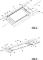
- fluid treatment chamber 12 may be defined, at least in part, by a tray 50 (housing 40 may also assist in defining fluid treatment chamber 12).
- a tray 50 housing 40 may also assist in defining fluid treatment chamber 12.
- a first embodiment of tray 50 is illustrated in Figs. 3 and 4
- a second embodiment of tray 50 is illustrated in Fig. 5 .
- Tray 50 may be made of a polymeric material in part, with certain sections of tray 50 made of another material, such as glass.
- tray 50 has a first recess or pocket 52 that defines fluid treatment chamber 12.
- Tray 50 may have one or more additional recesses or pockets 54, 56 that define, at least in part, overflow reservoir 32.
- the illustrated embodiments include two additional recesses 54, 56; this does not exclude the possibility that other embodiments may include only a single additional recess or may include more than two additional recesses.
- First recess 52 has a translucent floor 60 (see Figs. 4 and 5 ).
- Floor 60 is translucent to permit the illumination of biological fluid container 14 on both sides, for example, where, as here, light source 20 includes plurality of light sources 24, 28 arranged in one or more arrays 22, 26 disposed on either side of tray 50, and thus either side 16, 18 of fluid treatment chamber 12.
- Floor 60 may be made of glass, for example, disposed in a frame 62 that is attached or secured to the remainder of tray 50. In an embodiment of irradiation device 10 where container 14 is illuminated on only one side, floor 60 may be non-translucent.
- First recess 52 is defined by a rim or lip 64 disposed about the periphery of recess 52.
- the rim or lip 64 is useful in limiting the motion of container 14 relative to tray 50, to ensure that container 14 is adequately illuminated.
- first recess 52 is disposed approximately at the middle or center of tray 50, between opposing first and second ends 66, 68 of tray 50. While rim or lip 64 may be high enough to limit the motion of container 14 relative to tray 50, rim or lip 64 is not high enough to define a volume that would accept the entire contents of container 14, or to prevent the movement of leaking or leaked fluid out of first recess 52, particularly if agitator 30 is included and operational.
- tray 50 may include at least one recess 54, 56 in addition to first recess 52.
- tray 50 includes second recess 54 and third recess 56.
- Second recess 54 is disposed at first end 66 of tray 50 nearer to an end 70 of container 14 having ports 72 for accessing the contents of container 14.
- Third recess 56 is disposed at second end 72 of tray 50 further from port end 70 of container 14.
- second and third recesses 54, 56 define overflow reservoir 32.
- the single recess may be, for example, second recess 54 illustrated in the embodiment of Figs. 3 and 4 or that of Fig. 5 .
- Rim or lip 64 separates first recess 52 from second recess 54 and third recess 56, but does not prevent fluid communication between first, second and third recesses 52, 54, 56. This is particularly true where tray 50 is agitated while container 14 is illuminated, the agitation occurring as a consequence of an oscillatory motion applied to tray 50 along a longitudinal axis 74 of tray 50. The motion of tray 50 back and forth along longitudinal axis 74 may cause fluid to move up and over rim 64, and into second and/or third recess 54, 56.
- second and third recesses 54, 56 have a non-translucent floor 76, 78.
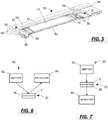
- This particular embodiment of the tray may be used with one or more non-contact sensors 34 in the form of an optical sensor, and in particular one or more reflective light sensors 80, an example of which is illustrated in the diagram of Fig. 6 .
- Reflective light sensor 80 of Fig. 6 includes a light emitter 82 and a light detector 84.
- Light emitter 82 and light detector 84 are both disposed on one side of overflow reservoir 32 (e.g., mounted on, in or to lid 42).
- a light beam (illustrated in the form of an arrow) is emitted from emitter 82 and is at least partially reflected off the floor (e.g., floor 76) or the fluid F and sensed by the detector 84.
- Optical sensor 80 may provide a signal to controller 38 when any amount of fluid is present in reservoir 32, or when a particular height of fluid is contained in the reservoir 32.
- second and third recesses 54, 56 have a translucent floor 86, 88.
- This particular embodiment of tray 50 may be used with one or more non-contact sensors 34 in the form of an optical sensor, and in particular one or more light absorption sensor 90, an example of which is illustrated in the diagram of Fig. 7 .
- Light absorption sensor 90 of Fig. 7 also includes a light emitter 92 and a light detector 94. However, light emitter 90 and light detector 94 are disposed on opposite sides of overflow reservoir 32 (e.g., one may be mounted on, in or to lid 42 and the other maybe mounted on, in or to base 44), and in particular opposite sides of translucent floor 86. A light beam (illustrated in the form of an arrow) is emitted from emitter 92 and is at least partially transmitted through the floor (e.g., floor 86) or the floor and fluid F and sensed by the detector 84. Optical sensor 90 may provide a signal to controller 38 when any amount of fluid is present in reservoir 32, or when a particular height of fluid is contained in reservoir 32.
- Optical sensor 90 may provide a signal to controller 38 when any amount of fluid is present in reservoir 32, or when a particular height of fluid is contained in reservoir 32.
- non-contact sensor 34 may be used with other materials placed in reservoir 32, which materials may facilitate detection of fluid in reservoir 32.
- reservoir 32 may include a compound that experiences a color change in the presence of the fluid, and sensor 34 may detect the color change of the material caused by the fluid, and generate a signal in response to the fluid as a consequence.
- the color-change material may be on a carrier (such as a piece of paper) that is affixed to the floor of reservoir 32.
- controller 38 is coupled to an indicator 36, one example of which is a light, such as a light emitting diode, and activates that indicator upon receipt of a signal from non-contact sensor 34.
- Indicator 36 may be used to provide an indication to the operator that the cycle should be terminated (manually by the operator) or will be terminated (automatically by controller 38) prior to the end of the normal cycle.
- Indicator 36 may take other forms of visible indicator, such as a display screen.
- Indicator 36 may also take the form of an audible indicator, such as a buzzer of other sound-producing element.
- Indicator 36 may be a haptic indicator, providing a tactile indication.
- Indicator 36 may be a combination of one or more of such visible, audible, haptic, etc. indicators.
- controller 38 may take the form of one or more electrical components or circuits
- controller 38 comprises a processor and an associated memory according to one embodiment.
- the processor may be programmed to carry out any of the actions that controller 38 is described as being configured to perform above.
- the processor may be programmed to activate indicator 36 upon receipt of the signal from the sensor 34.
- the processor may also be programmed to deactivate light source 20 subsequent to receipt of the signal from sensor 34, and to deactivate agitator 30.
- the instructions by which the processor is programmed may be stored on the memory associated with the processor, which memory may include one or more tangible non-transitory computer readable memories, having computer executable instructions stored thereon, which when executed by the processor, may cause the one or more processors to carry out one or more actions.
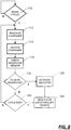
- the controller 38 may be programmed to carry out the following embodiment of a method of operating device 10, as explained with reference to the embodiment of irradiation device 10 illustrated in Figs. 1, 2 , and either Figs. 3, 4 and 6 or Figs. 5 and 7 . It will be understood that the method may be carried out by other embodiments of the irradiation device 10 as well.
- controller 38 may be coupled to a sensor disposed on housing, the sensor generating a signal when a biological fluid container 14 has been disposed in treatment chamber 12, and in particular in tray 50.
- the controller 38 may be coupled to an input device, such as a push button, that the user operates after biological fluid container 14 has been disposed in treatment chamber 12. In either event, controller 38 continues to monitor for a signal representative of the fact that the cycle should be initiated until such time as the signal is received.
- controller 38 activates light source 20, thereby illuminating biological fluid container 14 in fluid treatment chamber 12 (step 112).
- controller 38 may also activate agitator 30, thereby agitating biological fluid container 14 while biological fluid container 14 is illuminated (step 114).
- container 14 is illuminated and optionally agitated. While Fig. 8 illustrates that illumination (step 112) is initiated before agitation (step 114), this need not be the case according to all embodiments: initiation of agitation may precede illumination, or the two may be initiated as approximately the same time (i.e., "simultaneously").
- controller 38 checking sensor 34 (step 116) to determine if a signal has been received from non-contact sensor 34 disposed adjacent overflow reservoir 32 (step 118).
- the monitoring may occur simultaneously and in parallel with the illumination and the agitation of biological fluid container 14.
- controller 38 may then activate indicator 36 (step 120).
- controller 38 activates indicator 36 upon receipt of a signal from the sensor 34, i.e., with little or no delay in activation of indicator 36 once the signal has been received.
- Controller 38 may also deactivate illumination (and optionally agitation) of biological fluid container 14 subsequent to sensing the biological fluid in overflow reservoir 32 (step 122).
- controller 38 may deactivate the illumination and agitation of biological fluid container 14 automatically upon receipt of a signal from non-contact sensor 34, i.e., with little or no delay once the signal has been received and with no user input.
- the deactivation of illumination and agitation may proceed in either order, or may occur simultaneously. Further, deactivation of illumination and agitation may occur before, after or simultaneous with the activation of indicator 36.
- controller 38 may determine if the normal cycle termination has occurred (step 124). For example, the illumination of biological fluid container 14 may occur only until a period of time has elapsed, or until the contents of biological fluid container have exposed to an amount of irradiation. The time period and irradiation exposure may be selected by the user, or device 10 may be configured to irradiate container 14 in amounts determined by the manufacturer of device 10. If the normal cycle has not been completed, then the method may continue to irradiate (and agitate) the container and monitor sensor 34 (steps 112, 114, 116, 118). After the cycle has been complete, controller 38 may deactivate light source 20 and agitator 30 (step 122).
- the method may terminate, or controller 38 begin monitoring anew for a signal associated with the initiation of the cycle (step 110).
- irradiation device 10 may be used as a stand-alone device, irradiation device 10 may also be used in conjunction with a cell separator 210 as part of a system 300, as illustrated in Figs. 9-11 .
- the cell separator 210 would be configured to direct a biological fluid into a biological fluid container (e.g., container 14), and irradiation device 10 would include fluid treatment chamber 12 configured to receive biological fluid container 14, fluid treatment chamber 12 having opposing first and second sides 16, 18, light source 20 disposed adjacent at least one of first and second sides 16, 18 of fluid treatment chamber 12, overflow reservoir 32 in fluid communication with fluid treatment chamber 12 to receive fluid leaking from biological fluid container 14, non-contact sensor 34 disposed adjacent overflow reservoir 32 configured to generate a signal according to leaked fluid in overflow reservoir 32, indicator 36, and controller 38 coupled to light source 20, non-contact sensor 34 and indicator 36, controller 38 configured to activate indicator 36 upon receipt of the signal from sensor 34 and to deactivate light source 20 subsequent to receipt of the signal from sensor 34.
- a biological fluid container e.g., container 14
- irradiation device 10 would include fluid treatment chamber 12 configured to receive biological fluid container 14, fluid treatment chamber 12 having opposing first and second sides 16, 18, light source 20 disposed adjacent at least one of first and second sides 16,
- the cell separator 210 may be an Amicus® Separator made and sold by Fenwal, Inc., of Lake Zurich, Illinois. Mononuclear cell collections performed using a device such as the Amicus® are described in greater detail in U.S. Patent No. 6,027,657 .
- Figs. 9-11 show separator 210 in Fig. 9 , a representative blood centrifuge 212 (defining part of the separator 210) with a portion of a fluid circuit 214 mounted thereon in Fig. 10 , and the entire fluid circuit 214 in Fig. 11 .
- Fluid circuit (also referred to as a processing set) 214 includes a plurality of processing fluid flow cassettes 216, 218 and 220 (see Fig.
- Fluid circuit 214 also includes a network of tubing and pre-connected containers for establishing flow communication with the patient and for processing and collecting fluids and blood and blood components, as shown in greater detail in Fig. 11 .
- a separation chamber 222 is defined by the walls of a flexible processing container 224 carried within an annular gap defined by a rotating spool element 226 (see Fig. 10 ) and an outer bowl element (not shown).
- the processing container 224 takes the form of an elongated tube that is wrapped about the spool element 226 before use.
- the bowl and spool element 226 are pivoted on a yoke between an upright position and a suspended position, also not shown.
- the centrifuge 212 rotates the suspended bowl and spool element 226 about an axis, creating a centrifugal field within the processing chamber of container 224. Details of the mechanism for causing relative movement of the spool 226 and bowl elements as just described are disclosed in U.S. Patent No. 5,360,542 .
- the disposable processing set 214 may include flexible processing container 224, as well as a container 230 for supplying anticoagulant, a waste container 232 for collecting waste from one or more steps in the process for treating and washing mononuclear cells, a container 234 for holding saline or other wash or resuspension medium, a container 236 for collecting plasma, container 14 for collecting mononuclear cells from the operation discussed relative to Fig. 10 and, optionally, container 238 for holding a photoactivation agent.
- Container 14 is preferably pre-attached to with the disposable set 214.
- container 14 may be attached to set 214 by known sterile connection techniques, such as sterile docking or the like.
- fluid circuit includes inlet line 240, an anticoagulant (AC) line 242 for delivering AC from container 230, an RBC line 244 for conveying red blood cells from chamber 222 of container 224 to container 246, a platelet-poor plasma (PPP) line 248 for conveying PPP to container 236 and line 250 for conveying mononuclear cells to and from separation chamber 222 and collection/illumination container 14.
- the blood processing set 214 includes one or more venipuncture needle(s) for accessing the circulatory system of the patient.
- fluid circuit 214 includes inlet needle 252 and return needle 254.
- a single needle can serve as both the inlet and outlet needle.
- Container 14 is suitable for irradiation by light of a selected wavelength.
- suitable for irradiation it is meant that the walls of the container are sufficiently translucent to light of the selected wavelength.
- container walls made of ethylene vinyl acetate (EVA) are suitable.
- container 14 in which the mononuclear cells are collected may serve both as the collection container and the irradiation container.
- Container 14 may be placed inside irradiation device 10 by the operator or, more preferably, may be placed inside the irradiation chamber of irradiation device 10 at the beginning of a procedure including the cell separator and prior to whole blood withdrawal (as shown by the broken lines representing device 20 in Fig. 11 ). In any event, container 14 preferably remains integrally connected to the remainder of fluid circuit 214 during the entire procedure, thereby maintaining the closed or functionally closed condition of fluid circuit 214.
- Fluid flow through fluid circuit 214 is preferably driven, controlled and adjusted by a microprocessor-based controller in cooperation with the valves, pumps, weight scales and sensors of device 210 and fluid circuit 214, the details of which are described in the previously mentioned U.S. Patent No. 6,027,657 .
- the system 300 may be used for the treatment of mononuclear cells with ultraviolet light as illustrated in Fig. 12 .
- separator 210 receives whole blood that has been withdrawn from a patient (step 310). The whole blood is introduced into separation chamber 222 of separator 210, where the whole blood is subjected to a centrifugal field. The centrifugal field separates the target cell population, i.e., mononuclear cells (MNC), from red blood cells (RBC), platelets and plasma (step 312). The red blood cells and platelets separated at this stage may be returned to the patient, or optionally may be diverted to a container (e.g., container 246) for further processing.
- a container e.g., container 246
- red blood cells and plasma typically remains in suspension with the separated mononuclear cells. These red blood cells and plasma may be optionally removed prior to further processing (step 314).
- the removal of the residual red blood cells and plasma can have the effect of reducing irradiation time from, for example, approximately 30 minutes to approximately 5 minutes.
- a lysing agent is added to the suspended mononuclear cells, and then the suspension is incubated to activate the lysing agent to disintegrate or dissolve the red blood cells. The suspension is then washed using separator 210 to remove plasma and hemoglobin freed by the lysis of the red blood cells. The washed, lysed suspension is then resuspended.
- the residual red blood cells may be removed from the MNC suspension by using immunogenic cell separation techniques, in which paramagnetic beads coated with antibodies are used to bind the beads to antigens on the surface of the red blood cells, and the suspension is subjected to a magnetic force to separate the red blood cells, or additional density gradient separation (using, e.g., the centrifuge) may be performed.
- immunogenic cell separation techniques in which paramagnetic beads coated with antibodies are used to bind the beads to antigens on the surface of the red blood cells, and the suspension is subjected to a magnetic force to separate the red blood cells, or additional density gradient separation (using, e.g., the centrifuge) may be performed.
- the MNC suspension is subsequently combined with an activation agent (step 316), and then exposed to ultraviolet light (step 318) with the intent to obtain a treated cell product.
- the mononuclear cell product may be exposed to UV bulbs having a wavelength in the UVA range of about 320 nm to 400 nm for a selected period of time, preferably 5 minutes or less, resulting in an average UVA exposure of approximately 0.5-5.0 J/cm 2 .
- the container in which the MNC suspension and activation agent may also be moved to agitate the contents.
- non-contact sensor 34 may be used to check or monitor overflow reservoir 32 to determine if the contents are leaking from container 14 (step 320). If the determination is made that there is fluid in reservoir 32 (step 322) associated with possible leakage of contents from container 14, then indicator 36 may be activated (step 324) and light source 20 (and optionally agitator 30) may be deactivated (step 326). It will be recognized that as a consequence, the operation of device 10 may be terminated even though the entire operational cycle has not been completed.
- step 328 the operation of device 10 will continue until such time as the operational cycle is at an end (step 328) at which point light source 20 (and agitator 30) may be deactivated (step 326).
- step 328 the operational cycle is at an end
- step 326 point light source 20 (and agitator 30) may be deactivated.
- the treated cell product is then returned to the patient.
- the treated mononuclear cells may first be returned to separator 210 and concentrated to provide for the concentrated cells to have a smaller total volume as compared to un-concentrated cells. As a result, the smaller volume of concentrated MNCs may be more quickly reinfused to a patient.
- Automated control of the MNC collection and the irradiation treatment may be affected by the microprocessor-based controller of the respective separation device 210 and irradiation device 10 with some operator input for each device.
- operation of both separation device 210 and irradiation device 10 and the process steps carried out by each may be remotely controlled by a separate controller (e.g., a computer) that communicates with both.
- the disclosed device, method and system may include one or more of the aspects set forth below.
- an irradiation device in a first aspect, includes a fluid treatment chamber configured to receive a biological fluid container, the fluid treatment chamber having opposing first and second sides, at least one light source disposed adjacent at least one of the first and second sides of the fluid treatment chamber, and an overflow reservoir in fluid communication with the fluid treatment chamber to receive fluid leaking from the biological fluid container.
- the irradiation device also includes a non-contact sensor disposed adjacent the overflow reservoir and configured to generate a signal according to leaked fluid in the overflow reservoir, an indicator, and a controller coupled to the at least one light source, the non-contact sensor and the indicator, the controller configured to activate the indicator upon receipt of the signal from the sensor and to deactivate the at least one light source subsequent to receipt of the signal from the sensor.
- the irradiation device includes an agitator coupled to the fluid treatment chamber to move the fluid treatment chamber with an oscillatory motion, the controller coupled to the agitator and configured to deactivate the agitator subsequent to receipt of the signal from the sensor.
- the irradiation device includes a tray, the tray having a first recess defining the fluid treatment chamber and a second recess defining at least in part the overflow reservoir.
- the tray may have a lip that separates the first recess from the second recess.
- the tray may have a first end and a second end, the second recess disposed at the first end of the tray.
- the tray may have a third recess, the third recess disposed at the second end of the tray, and the second and third recesses defining the overflow reservoir.
- the first recess has a translucent floor
- the second (and third) recess may have a translucent or a non-translucent floor.
- the non-contact sensor is an optical sensor, such as a reflective light sensor or a light absorption sensor.
- a reflective light sensor may include a light emitter and a light detector, the light emitter and light detector both disposed on one side of the overflow reservoir.
- a light absorption sensor may include a light emitter and a light detector, the overflow reservoir having a translucent floor, the light emitter and the light detector disposed on opposite sides of the overflow reservoir.
- the controller is configured to automatically deactivate the at least one light source upon receipt of the signal from the overflow reservoir.
- the controller may include a processor and memory, and the processor may be programmed to activate the indicator upon receipt of the signal from the overflow reservoir and to deactivate the at least one light source subsequent to receipt of the signal from the overflow reservoir.
- a method of controlling an irradiation device includes Illuminating a biological fluid container in a fluid treatment chamber, sensing biological fluid from the fluid container in overflow reservoir in fluid communication with the fluid treatment chamber using a non-contact sensor, activating an indicator after sensing the biological fluid in the overflow reservoir, and deactivating illumination of the biological fluid container subsequent to sensing the biological fluid in the overflow reservoir.
- the method may include automatically deactivating illumination of the biological fluid container subsequent to sensing the biological fluid in the overflow reservoir.
- the method may include agitating the biological fluid container while illuminating the biological fluid container, the method may include deactivating agitation of the biological fluid container subsequent to sensing the biological fluid in the overflow reservoir.
- the method may include automatically deactivating agitation of the biological fluid container subsequent to sensing the biological fluid in the overflow reservoir.
- the method may include sensing biological fluid from the fluid container in overflow reservoir in fluid communication with the fluid treatment chamber using an optical sensor.
- a system in another related aspect, includes a cell separator configured to direct a biological fluid into a biological fluid container and an irradiation device.
- the irradiation device is configured according to any one, or combinations, of the aspects above, or configured to perform the methods of any one, or combinations, of the aspects above.
Landscapes
- Health & Medical Sciences (AREA)
- Life Sciences & Earth Sciences (AREA)
- Engineering & Computer Science (AREA)
- Heart & Thoracic Surgery (AREA)
- Vascular Medicine (AREA)
- Biomedical Technology (AREA)
- General Health & Medical Sciences (AREA)
- Veterinary Medicine (AREA)
- Public Health (AREA)
- Animal Behavior & Ethology (AREA)
- Hematology (AREA)
- Chemical & Material Sciences (AREA)
- Anesthesiology (AREA)
- Cardiology (AREA)
- Wood Science & Technology (AREA)
- Bioinformatics & Cheminformatics (AREA)
- Zoology (AREA)
- Organic Chemistry (AREA)
- Genetics & Genomics (AREA)
- Biotechnology (AREA)
- Microbiology (AREA)
- Biochemistry (AREA)
- General Engineering & Computer Science (AREA)
- Sustainable Development (AREA)
- Analytical Chemistry (AREA)
- Epidemiology (AREA)
- Immunology (AREA)
- Computer Hardware Design (AREA)
- Molecular Biology (AREA)
- Cell Biology (AREA)
- External Artificial Organs (AREA)
- Apparatus For Disinfection Or Sterilisation (AREA)
Claims (15)
- Bestrahlungsvorrichtung (10), umfassend:
eine Flüssigkeitsbehandlungskammer (12), die zum Aufnehmen eines Behälter mit biologischer Flüssigkeit (14) ausgelegt ist, wobei die Flüssigkeitsbehandlungskammer (12) eine erste und eine zweite gegenüberliegende Seite (16, 18) aufweist;mindestens eine Lichtquelle (20), die benachbart zu mindestens einer der ersten und der zweiten Seite (16, 18) der Flüssigkeitsbehandlungskammer (12) angeordnet ist; undeinen Indikator (36);gekennzeichnet durchein Überlaufreservoir (32) in Fluidverbindung mit der Flüssigkeitsbehandlungskammer (12) zum Aufnehmen von Flüssigkeit, die aus dem Behälter mit biologischer Flüssigkeit (14) ausläuft;einen berührungslosen optischen Sensor (34), der benachbart zum Überlaufreservoir (32) angeordnet und zum Generieren eines Signals gemäß der ausgelaufenen Flüssigkeit im Überlaufreservoir (32) ausgelegt ist; undeine Steuerung (38), die mit der mindestens einen Lichtquelle (20), dem berührungslosen Sensor (34) und dem Indikator (36) gekoppelt ist, wobei die Steuerung (38) zum Aktivieren des Indikators (36) bei Empfang des Signals vom Sensor (34) und zum Deaktivieren der mindestens einen Lichtquelle (20) nach dem Empfang des Signals vom Sensor (34) ausgelegt ist. - Bestrahlungsvorrichtung (10) nach Anspruch 1, ferner umfassend:eine Schüttelvorrichtung (30), die mit der Flüssigkeitsbehandlungskammer (12) zum Bewegen der Flüssigkeitsbehandlungskammer (12) mit einer schwingenden Bewegung gekoppelt ist,wobei die Steuerung (38) mit der Schüttelvorrichtung (30) gekoppelt ist, und die Steuerung (38) zum Deaktivieren der Schüttelvorrichtung (30) nach dem Empfang des Signals vom Sensor (34) ausgelegt ist.
- Bestrahlungsvorrichtung (10) nach Anspruch 1 oder 2, ferner umfassend eine Wanne (50), wobei die Wanne (50) eine erste Aussparung (52), welche die Flüssigkeitsbehandlungskammer (12) definiert, und eine zweite Aussparung (54) aufweist, die wenigstens zum Teil das Überlaufreservoir (32) definiert, wobei die erste Aussparung (52) einen durchscheinenden Boden (60) aufweist.
- Bestrahlungsvorrichtung (10) nach Anspruch 3, wobei die Wanne (50) eine Lippe (64) aufweist, welche die erste Aussparung (52) von der zweiten Aussparung (54) trennt.
- Bestrahlungsvorrichtung (10) nach Anspruch 3 oder 4, wobei die Wanne (50) ein erstes Ende (70) und ein zweites Ende (72) aufweist, wobei die zweite Aussparung (54) am ersten Ende (70) der Wanne (50) angeordnet ist.
- Bestrahlungsvorrichtung (10) nach Anspruch 5, wobei die Wanne (50) eine dritte Aussparung (56) aufweist, wobei die dritte Aussparung (56) am zweiten Ende (72) der Wanne (50) angeordnet ist, und die zweite und dritte Aussparung (54, 56) das Überlaufreservoir (32) definieren.
- Bestrahlungsvorrichtung (10) nach einem der Ansprüche 3 bis 6, wobei die zweite Aussparung (54) und gegebenenfalls die dritte Aussparung (56) einen durchscheinenden Boden (60) aufweisen.
- Bestrahlungsvorrichtung (10) nach einem der Ansprüche 1 bis 7, wobei der berührungslose optische Sensor (34) ein Reflexionslichtsensor ist.
- Bestrahlungsvorrichtung (10) nach Anspruch 8, wobei der berührungslose Sensor (34) ein Reflexionslichtsensor (80) ist, der einen Lichtsender (82) und einen Lichtdetektor (84) umfasst, wobei der Lichtsender (82) und der Lichtdetektor (84) beide auf einer Seite des Überlaufreservoirs (32) angeordnet sind.
- Bestrahlungsvorrichtung (10) nach einem der Ansprüche 1 bis 7, wobei der berührungslose optische Sensor (34) ein Lichtabsorptionssensor (90) ist, der einen Lichtsender (92) und einen Lichtdetektor (94) umfasst, wobei das Überlaufreservoir (32) einen durchscheinenden Boden aufweist, und der Lichtsender (90) und der Lichtdetektor (2) auf gegenüberliegenden Seiten des Überlaufreservoirs (32) angeordnet sind.
- Bestrahlungsvorrichtung (10) nach einem der Ansprüche 1 bis 10, wobei die Steuerung (38) zum automatischen Deaktivieren der mindestens einen Lichtquelle (20) bei Empfang des Signals vom Überlaufreservoir (32) ausgelegt ist.
- Verfahren zur Steuerung einer Bestrahlungsvorrichtung (10), wobei das Verfahren umfasst:Beleuchten eines Behälters mit biologischer Flüssigkeit (14) in einer Flüssigkeitsbehandlungskammer (12) ;Messen einer biologischen Flüssigkeit aus dem Flüssigkeitsbehälter (14) in einem Überlaufreservoir (32) in Fluidverbindung mit der Flüssigkeitsbehandlungskammer (12) unter Verwendung eines berührungslosen optischen Sensors (34);Aktivieren eines Indikators (36) nach dem Messen der biologischen Flüssigkeit im Überlaufreservoir (32); undDeaktivieren von Beleuchtung des Behälters mit biologischer Flüssigkeit (14) nach dem Messen der biologischen Flüssigkeit im Überlaufreservoir (32).
- Verfahren nach Anspruch 12, wobei das Deaktivieren der Beleuchtung des Behälters mit biologischer Flüssigkeit (14) ein automatisches Deaktivieren von Beleuchtung des Behälters mit biologischer Flüssigkeit (14) nach dem Messen der biologischen Flüssigkeit im Überlaufreservoir (32) umfasst.
- Verfahren nach Anspruch 12 oder 13, ferner umfassend:Schütteln des Behälters mit biologischer Flüssigkeit (14) während des Beleuchtens des Behälters mit biologischer Flüssigkeit (14); undDeaktivieren des Schüttelns des Behälters mit biologischer Flüssigkeit (14) nach dem Messen der biologischen Flüssigkeit im Überlaufreservoir (32).
- Verfahren nach Anspruch 14, wobei das Deaktivieren des Schüttelns des Behälters mit biologischer Flüssigkeit (14) ein automatisches Deaktivieren des Schüttelns des Behälters mit biologischer Flüssigkeit (14) nach dem Messen der biologischen Flüssigkeit im Überlaufreservoir (32) umfasst.
Applications Claiming Priority (2)
| Application Number | Priority Date | Filing Date | Title |
|---|---|---|---|
| US14/810,058 US9816073B2 (en) | 2015-07-27 | 2015-07-27 | Systems and methods for detecting fluid leaks using a non-contact sensor |
| PCT/US2016/043147 WO2017019408A1 (en) | 2015-07-27 | 2016-07-20 | Systems and methods for detecting fluid leaks using a non-contact sensor |
Publications (2)
| Publication Number | Publication Date |
|---|---|
| EP3328443A1 EP3328443A1 (de) | 2018-06-06 |
| EP3328443B1 true EP3328443B1 (de) | 2019-09-04 |
Family
ID=56740449
Family Applications (1)
| Application Number | Title | Priority Date | Filing Date |
|---|---|---|---|
| EP16754012.9A Active EP3328443B1 (de) | 2015-07-27 | 2016-07-20 | Systeme und verfahren zur erkennung von flüssigkeitslecks mit einem berührungslosen, optischen sensor |
Country Status (3)
| Country | Link |
|---|---|
| US (1) | US9816073B2 (de) |
| EP (1) | EP3328443B1 (de) |
| WO (1) | WO2017019408A1 (de) |
Cited By (1)
| Publication number | Priority date | Publication date | Assignee | Title |
|---|---|---|---|---|
| WO2022016855A1 (zh) * | 2020-04-30 | 2022-01-27 | 珠海丽珠试剂股份有限公司 | 一种血液辐照仪的屏蔽壳体及该屏蔽壳体的制造方法 |
Families Citing this family (12)
| Publication number | Priority date | Publication date | Assignee | Title |
|---|---|---|---|---|
| WO2016183032A1 (en) | 2015-05-08 | 2016-11-17 | Biomagnetic Solutions Llc | Apparatus and method for immunomagnetic cell separation |
| US20170028121A1 (en) * | 2015-07-31 | 2017-02-02 | Fenwal, Inc. | Irradiation device for biological fluids |
| US10751433B2 (en) | 2016-11-28 | 2020-08-25 | Fenwal, Inc. | Systems and methods for controlling an irradiation device |
| WO2019216887A1 (en) * | 2018-05-08 | 2019-11-14 | Biomagnetic Solutions Llc | A rigid chamber for cell separation from a flexible disposable bag |
| EP3666311B1 (de) | 2018-12-13 | 2026-02-04 | Fenwal, Inc. | Systeme und verfahren zur behandlung einer biologischen flüssigkeit mit licht im fall eines glühlampenausfalls |
| US11504463B2 (en) | 2019-01-10 | 2022-11-22 | Fenwal, Inc. | Systems and methods for verifying that a biological product is ready for treatment |
| US11883543B2 (en) | 2019-04-16 | 2024-01-30 | Fenwal, Inc. | Systems and methods for photoactivation of a biological fluid |
| US12228564B2 (en) * | 2020-01-10 | 2025-02-18 | Fresenius Medical Care Holdings, Inc. | Systems and methods for analyzing spent dialysate |
| IT202000003407A1 (it) * | 2020-02-19 | 2021-08-19 | Pelham Crescent S R L | Macchina per la fotoferesi extracorporea di un fluido biologico |
| US12036344B2 (en) * | 2020-11-13 | 2024-07-16 | Fresenius Medical Care Holdings, Inc. | Systems and methods for analyzing spent dialysate |
| DE102020216088A1 (de) * | 2020-12-16 | 2022-06-23 | Fraunhofer-Gesellschaft zur Förderung der angewandten Forschung eingetragener Verein | Modulare Bestrahlungsvorrichtung und Bestrahlungsverfahren |
| US11844888B1 (en) * | 2021-03-12 | 2023-12-19 | Danilo O. Fernandez | Photonic corpuscular irradiator machine |
Family Cites Families (10)
| Publication number | Priority date | Publication date | Assignee | Title |
|---|---|---|---|---|
| JP4065927B2 (ja) | 1991-12-23 | 2008-03-26 | バクスター、インターナショナル、インコーポレイテッド | 分離チャンバーへのアクセスを提供する分離可能なボウル及びスプール要素を有する遠心機 |
| US20020192632A1 (en) | 1995-06-07 | 2002-12-19 | Hei Derek J. | Method and devices for the removal of psoralens from blood products |
| US6027657A (en) | 1997-07-01 | 2000-02-22 | Baxter International Inc. | Systems and methods for collecting diluted mononuclear cells |
| US7068361B2 (en) * | 1999-06-03 | 2006-06-27 | Baxter International | Apparatus, systems and methods for processing and treating a biological fluid with light |
| JP5008103B2 (ja) | 2007-07-02 | 2012-08-22 | テルモ ビーシーティー バイオテクノロジーズ,エルエルシー | 測定手段を用いて血液中および血液生成物中の汚染物質を光還元するための装置 |
| GB0804884D0 (en) | 2008-03-15 | 2008-04-16 | Filup Ltd | Water dispensing apparatus |
| WO2010132167A1 (en) | 2009-05-11 | 2010-11-18 | Caridianbct Biotechnologies, Llc | Stable calibration means for apparatus for photo reduction of contaminants in blood |
| CA2774034C (en) | 2009-10-13 | 2017-05-09 | Sebastian Schmidt | Method for deactivating undesired contaminations in leech extracts |
| US8864275B2 (en) * | 2011-12-14 | 2014-10-21 | Xerox Corporation | System for detecting leakage of phase change inks |
| US10213544B2 (en) | 2013-06-13 | 2019-02-26 | Fenwal, Inc. | Methods for treating a suspension of mononuclear cells to facilitate extracorporeal photopheresis |
-
2015
- 2015-07-27 US US14/810,058 patent/US9816073B2/en active Active
-
2016
- 2016-07-20 EP EP16754012.9A patent/EP3328443B1/de active Active
- 2016-07-20 WO PCT/US2016/043147 patent/WO2017019408A1/en not_active Ceased
Non-Patent Citations (1)
| Title |
|---|
| None * |
Cited By (1)
| Publication number | Priority date | Publication date | Assignee | Title |
|---|---|---|---|---|
| WO2022016855A1 (zh) * | 2020-04-30 | 2022-01-27 | 珠海丽珠试剂股份有限公司 | 一种血液辐照仪的屏蔽壳体及该屏蔽壳体的制造方法 |
Also Published As
| Publication number | Publication date |
|---|---|
| US9816073B2 (en) | 2017-11-14 |
| WO2017019408A1 (en) | 2017-02-02 |
| EP3328443A1 (de) | 2018-06-06 |
| US20170029776A1 (en) | 2017-02-02 |
Similar Documents
| Publication | Publication Date | Title |
|---|---|---|
| EP3328443B1 (de) | Systeme und verfahren zur erkennung von flüssigkeitslecks mit einem berührungslosen, optischen sensor | |
| US11577016B2 (en) | System and method for irradiating biological fluids | |
| US10213544B2 (en) | Methods for treating a suspension of mononuclear cells to facilitate extracorporeal photopheresis | |
| US9974899B2 (en) | Method for delivering desired light dose to cells in a light attenuating medium | |
| US11504463B2 (en) | Systems and methods for verifying that a biological product is ready for treatment | |
| EP3632484B1 (de) | Systeme zum sammeln von proben in einem photophereseverfahren | |
| US12290624B2 (en) | System and method for irradiating biological fluids | |
| US10434240B2 (en) | Methods and systems for processing and washing a photopheresis mononuclear cell product | |
| EP3902581B1 (de) | Systeme und verfahren zur extrakorporalen photopherese mit geringem volumen | |
| US12097383B2 (en) | Systems and methods for treating a biological fluid with light in the event of a bulb outage | |
| DK1867355T3 (en) | System for photo irradiation of blood or fractions thereof, and the procedure thereof | |
| US11883543B2 (en) | Systems and methods for photoactivation of a biological fluid | |
| JP2012010663A (ja) | 細胞分離装置 | |
| AU2024262293A1 (en) | Methods and systems for determining subject specific amounts for collection |
Legal Events
| Date | Code | Title | Description |
|---|---|---|---|
| STAA | Information on the status of an ep patent application or granted ep patent |
Free format text: STATUS: THE INTERNATIONAL PUBLICATION HAS BEEN MADE |
|
| PUAI | Public reference made under article 153(3) epc to a published international application that has entered the european phase |
Free format text: ORIGINAL CODE: 0009012 |
|
| STAA | Information on the status of an ep patent application or granted ep patent |
Free format text: STATUS: REQUEST FOR EXAMINATION WAS MADE |
|
| 17P | Request for examination filed |
Effective date: 20180215 |
|
| AK | Designated contracting states |
Kind code of ref document: A1 Designated state(s): AL AT BE BG CH CY CZ DE DK EE ES FI FR GB GR HR HU IE IS IT LI LT LU LV MC MK MT NL NO PL PT RO RS SE SI SK SM TR |
|
| AX | Request for extension of the european patent |
Extension state: BA ME |
|
| DAV | Request for validation of the european patent (deleted) | ||
| DAX | Request for extension of the european patent (deleted) | ||
| GRAP | Despatch of communication of intention to grant a patent |
Free format text: ORIGINAL CODE: EPIDOSNIGR1 |
|
| STAA | Information on the status of an ep patent application or granted ep patent |
Free format text: STATUS: GRANT OF PATENT IS INTENDED |
|
| INTG | Intention to grant announced |
Effective date: 20181210 |
|
| GRAJ | Information related to disapproval of communication of intention to grant by the applicant or resumption of examination proceedings by the epo deleted |
Free format text: ORIGINAL CODE: EPIDOSDIGR1 |
|
| STAA | Information on the status of an ep patent application or granted ep patent |
Free format text: STATUS: REQUEST FOR EXAMINATION WAS MADE |
|
| GRAP | Despatch of communication of intention to grant a patent |
Free format text: ORIGINAL CODE: EPIDOSNIGR1 |
|
| STAA | Information on the status of an ep patent application or granted ep patent |
Free format text: STATUS: GRANT OF PATENT IS INTENDED |
|
| INTC | Intention to grant announced (deleted) | ||
| INTG | Intention to grant announced |
Effective date: 20190225 |
|
| GRAS | Grant fee paid |
Free format text: ORIGINAL CODE: EPIDOSNIGR3 |
|
| GRAA | (expected) grant |
Free format text: ORIGINAL CODE: 0009210 |
|
| STAA | Information on the status of an ep patent application or granted ep patent |
Free format text: STATUS: THE PATENT HAS BEEN GRANTED |
|
| AK | Designated contracting states |
Kind code of ref document: B1 Designated state(s): AL AT BE BG CH CY CZ DE DK EE ES FI FR GB GR HR HU IE IS IT LI LT LU LV MC MK MT NL NO PL PT RO RS SE SI SK SM TR |
|
| REG | Reference to a national code |
Ref country code: GB Ref legal event code: FG4D |
|
| REG | Reference to a national code |
Ref country code: CH Ref legal event code: EP |
|
| REG | Reference to a national code |
Ref country code: AT Ref legal event code: REF Ref document number: 1174430 Country of ref document: AT Kind code of ref document: T Effective date: 20190915 |
|
| REG | Reference to a national code |
Ref country code: DE Ref legal event code: R096 Ref document number: 602016020019 Country of ref document: DE |
|
| REG | Reference to a national code |
Ref country code: IE Ref legal event code: FG4D |
|
| REG | Reference to a national code |
Ref country code: NL Ref legal event code: MP Effective date: 20190904 |
|
| REG | Reference to a national code |
Ref country code: LT Ref legal event code: MG4D |
|
| PG25 | Lapsed in a contracting state [announced via postgrant information from national office to epo] |
Ref country code: FI Free format text: LAPSE BECAUSE OF FAILURE TO SUBMIT A TRANSLATION OF THE DESCRIPTION OR TO PAY THE FEE WITHIN THE PRESCRIBED TIME-LIMIT Effective date: 20190904 Ref country code: LT Free format text: LAPSE BECAUSE OF FAILURE TO SUBMIT A TRANSLATION OF THE DESCRIPTION OR TO PAY THE FEE WITHIN THE PRESCRIBED TIME-LIMIT Effective date: 20190904 Ref country code: HR Free format text: LAPSE BECAUSE OF FAILURE TO SUBMIT A TRANSLATION OF THE DESCRIPTION OR TO PAY THE FEE WITHIN THE PRESCRIBED TIME-LIMIT Effective date: 20190904 Ref country code: NO Free format text: LAPSE BECAUSE OF FAILURE TO SUBMIT A TRANSLATION OF THE DESCRIPTION OR TO PAY THE FEE WITHIN THE PRESCRIBED TIME-LIMIT Effective date: 20191204 Ref country code: SE Free format text: LAPSE BECAUSE OF FAILURE TO SUBMIT A TRANSLATION OF THE DESCRIPTION OR TO PAY THE FEE WITHIN THE PRESCRIBED TIME-LIMIT Effective date: 20190904 Ref country code: BG Free format text: LAPSE BECAUSE OF FAILURE TO SUBMIT A TRANSLATION OF THE DESCRIPTION OR TO PAY THE FEE WITHIN THE PRESCRIBED TIME-LIMIT Effective date: 20191204 |
|
| PG25 | Lapsed in a contracting state [announced via postgrant information from national office to epo] |
Ref country code: ES Free format text: LAPSE BECAUSE OF FAILURE TO SUBMIT A TRANSLATION OF THE DESCRIPTION OR TO PAY THE FEE WITHIN THE PRESCRIBED TIME-LIMIT Effective date: 20190904 Ref country code: GR Free format text: LAPSE BECAUSE OF FAILURE TO SUBMIT A TRANSLATION OF THE DESCRIPTION OR TO PAY THE FEE WITHIN THE PRESCRIBED TIME-LIMIT Effective date: 20191205 Ref country code: AL Free format text: LAPSE BECAUSE OF FAILURE TO SUBMIT A TRANSLATION OF THE DESCRIPTION OR TO PAY THE FEE WITHIN THE PRESCRIBED TIME-LIMIT Effective date: 20190904 Ref country code: LV Free format text: LAPSE BECAUSE OF FAILURE TO SUBMIT A TRANSLATION OF THE DESCRIPTION OR TO PAY THE FEE WITHIN THE PRESCRIBED TIME-LIMIT Effective date: 20190904 Ref country code: RS Free format text: LAPSE BECAUSE OF FAILURE TO SUBMIT A TRANSLATION OF THE DESCRIPTION OR TO PAY THE FEE WITHIN THE PRESCRIBED TIME-LIMIT Effective date: 20190904 |
|
| REG | Reference to a national code |
Ref country code: AT Ref legal event code: MK05 Ref document number: 1174430 Country of ref document: AT Kind code of ref document: T Effective date: 20190904 |
|
| PG25 | Lapsed in a contracting state [announced via postgrant information from national office to epo] |
Ref country code: EE Free format text: LAPSE BECAUSE OF FAILURE TO SUBMIT A TRANSLATION OF THE DESCRIPTION OR TO PAY THE FEE WITHIN THE PRESCRIBED TIME-LIMIT Effective date: 20190904 Ref country code: PL Free format text: LAPSE BECAUSE OF FAILURE TO SUBMIT A TRANSLATION OF THE DESCRIPTION OR TO PAY THE FEE WITHIN THE PRESCRIBED TIME-LIMIT Effective date: 20190904 Ref country code: IT Free format text: LAPSE BECAUSE OF FAILURE TO SUBMIT A TRANSLATION OF THE DESCRIPTION OR TO PAY THE FEE WITHIN THE PRESCRIBED TIME-LIMIT Effective date: 20190904 Ref country code: RO Free format text: LAPSE BECAUSE OF FAILURE TO SUBMIT A TRANSLATION OF THE DESCRIPTION OR TO PAY THE FEE WITHIN THE PRESCRIBED TIME-LIMIT Effective date: 20190904 Ref country code: NL Free format text: LAPSE BECAUSE OF FAILURE TO SUBMIT A TRANSLATION OF THE DESCRIPTION OR TO PAY THE FEE WITHIN THE PRESCRIBED TIME-LIMIT Effective date: 20190904 Ref country code: AT Free format text: LAPSE BECAUSE OF FAILURE TO SUBMIT A TRANSLATION OF THE DESCRIPTION OR TO PAY THE FEE WITHIN THE PRESCRIBED TIME-LIMIT Effective date: 20190904 Ref country code: PT Free format text: LAPSE BECAUSE OF FAILURE TO SUBMIT A TRANSLATION OF THE DESCRIPTION OR TO PAY THE FEE WITHIN THE PRESCRIBED TIME-LIMIT Effective date: 20200106 |
|
| PG25 | Lapsed in a contracting state [announced via postgrant information from national office to epo] |
Ref country code: SK Free format text: LAPSE BECAUSE OF FAILURE TO SUBMIT A TRANSLATION OF THE DESCRIPTION OR TO PAY THE FEE WITHIN THE PRESCRIBED TIME-LIMIT Effective date: 20190904 Ref country code: SM Free format text: LAPSE BECAUSE OF FAILURE TO SUBMIT A TRANSLATION OF THE DESCRIPTION OR TO PAY THE FEE WITHIN THE PRESCRIBED TIME-LIMIT Effective date: 20190904 Ref country code: IS Free format text: LAPSE BECAUSE OF FAILURE TO SUBMIT A TRANSLATION OF THE DESCRIPTION OR TO PAY THE FEE WITHIN THE PRESCRIBED TIME-LIMIT Effective date: 20200224 Ref country code: CZ Free format text: LAPSE BECAUSE OF FAILURE TO SUBMIT A TRANSLATION OF THE DESCRIPTION OR TO PAY THE FEE WITHIN THE PRESCRIBED TIME-LIMIT Effective date: 20190904 |
|
| REG | Reference to a national code |
Ref country code: DE Ref legal event code: R097 Ref document number: 602016020019 Country of ref document: DE |
|
| PLBE | No opposition filed within time limit |
Free format text: ORIGINAL CODE: 0009261 |
|
| STAA | Information on the status of an ep patent application or granted ep patent |
Free format text: STATUS: NO OPPOSITION FILED WITHIN TIME LIMIT |
|
| PG2D | Information on lapse in contracting state deleted |
Ref country code: IS |
|
| PG25 | Lapsed in a contracting state [announced via postgrant information from national office to epo] |
Ref country code: DK Free format text: LAPSE BECAUSE OF FAILURE TO SUBMIT A TRANSLATION OF THE DESCRIPTION OR TO PAY THE FEE WITHIN THE PRESCRIBED TIME-LIMIT Effective date: 20190904 Ref country code: IS Free format text: LAPSE BECAUSE OF FAILURE TO SUBMIT A TRANSLATION OF THE DESCRIPTION OR TO PAY THE FEE WITHIN THE PRESCRIBED TIME-LIMIT Effective date: 20200105 |
|
| 26N | No opposition filed |
Effective date: 20200605 |
|
| PG25 | Lapsed in a contracting state [announced via postgrant information from national office to epo] |
Ref country code: SI Free format text: LAPSE BECAUSE OF FAILURE TO SUBMIT A TRANSLATION OF THE DESCRIPTION OR TO PAY THE FEE WITHIN THE PRESCRIBED TIME-LIMIT Effective date: 20190904 |
|
| PG25 | Lapsed in a contracting state [announced via postgrant information from national office to epo] |
Ref country code: MC Free format text: LAPSE BECAUSE OF FAILURE TO SUBMIT A TRANSLATION OF THE DESCRIPTION OR TO PAY THE FEE WITHIN THE PRESCRIBED TIME-LIMIT Effective date: 20190904 |
|
| REG | Reference to a national code |
Ref country code: CH Ref legal event code: PL |
|
| REG | Reference to a national code |
Ref country code: BE Ref legal event code: MM Effective date: 20200731 |
|
| PG25 | Lapsed in a contracting state [announced via postgrant information from national office to epo] |
Ref country code: LI Free format text: LAPSE BECAUSE OF NON-PAYMENT OF DUE FEES Effective date: 20200731 Ref country code: LU Free format text: LAPSE BECAUSE OF NON-PAYMENT OF DUE FEES Effective date: 20200720 Ref country code: CH Free format text: LAPSE BECAUSE OF NON-PAYMENT OF DUE FEES Effective date: 20200731 |
|
| PG25 | Lapsed in a contracting state [announced via postgrant information from national office to epo] |
Ref country code: BE Free format text: LAPSE BECAUSE OF NON-PAYMENT OF DUE FEES Effective date: 20200731 |
|
| PG25 | Lapsed in a contracting state [announced via postgrant information from national office to epo] |
Ref country code: IE Free format text: LAPSE BECAUSE OF NON-PAYMENT OF DUE FEES Effective date: 20200720 |
|
| PG25 | Lapsed in a contracting state [announced via postgrant information from national office to epo] |
Ref country code: TR Free format text: LAPSE BECAUSE OF FAILURE TO SUBMIT A TRANSLATION OF THE DESCRIPTION OR TO PAY THE FEE WITHIN THE PRESCRIBED TIME-LIMIT Effective date: 20190904 Ref country code: MT Free format text: LAPSE BECAUSE OF FAILURE TO SUBMIT A TRANSLATION OF THE DESCRIPTION OR TO PAY THE FEE WITHIN THE PRESCRIBED TIME-LIMIT Effective date: 20190904 Ref country code: CY Free format text: LAPSE BECAUSE OF FAILURE TO SUBMIT A TRANSLATION OF THE DESCRIPTION OR TO PAY THE FEE WITHIN THE PRESCRIBED TIME-LIMIT Effective date: 20190904 |
|
| PG25 | Lapsed in a contracting state [announced via postgrant information from national office to epo] |
Ref country code: MK Free format text: LAPSE BECAUSE OF FAILURE TO SUBMIT A TRANSLATION OF THE DESCRIPTION OR TO PAY THE FEE WITHIN THE PRESCRIBED TIME-LIMIT Effective date: 20190904 |
|
| P01 | Opt-out of the competence of the unified patent court (upc) registered |
Effective date: 20230515 |
|
| PGFP | Annual fee paid to national office [announced via postgrant information from national office to epo] |
Ref country code: DE Payment date: 20250729 Year of fee payment: 10 |
|
| PGFP | Annual fee paid to national office [announced via postgrant information from national office to epo] |
Ref country code: GB Payment date: 20250728 Year of fee payment: 10 |
|
| PGFP | Annual fee paid to national office [announced via postgrant information from national office to epo] |
Ref country code: FR Payment date: 20250725 Year of fee payment: 10 |