EP3328302B1 - Interspinale stabilisierungs- und fusionsvorrichtung - Google Patents
Interspinale stabilisierungs- und fusionsvorrichtung Download PDFInfo
- Publication number
- EP3328302B1 EP3328302B1 EP16833643.6A EP16833643A EP3328302B1 EP 3328302 B1 EP3328302 B1 EP 3328302B1 EP 16833643 A EP16833643 A EP 16833643A EP 3328302 B1 EP3328302 B1 EP 3328302B1
- Authority
- EP
- European Patent Office
- Prior art keywords
- bone
- receiving
- lateral walls
- inferior
- fusion
- Prior art date
- Legal status (The legal status is an assumption and is not a legal conclusion. Google has not performed a legal analysis and makes no representation as to the accuracy of the status listed.)
- Active
Links
Images


Classifications
-
- A—HUMAN NECESSITIES
- A61—MEDICAL OR VETERINARY SCIENCE; HYGIENE
- A61B—DIAGNOSIS; SURGERY; IDENTIFICATION
- A61B17/00—Surgical instruments, devices or methods
- A61B17/56—Surgical instruments or methods for treatment of bones or joints; Devices specially adapted therefor
- A61B17/58—Surgical instruments or methods for treatment of bones or joints; Devices specially adapted therefor for osteosynthesis, e.g. bone plates, screws or setting implements
- A61B17/68—Internal fixation devices, including fasteners and spinal fixators, even if a part thereof projects from the skin
- A61B17/70—Spinal positioners or stabilisers, e.g. stabilisers comprising fluid filler in an implant
- A61B17/7062—Devices acting on, attached to, or simulating the effect of, vertebral processes, vertebral facets or ribs ; Tools for such devices
- A61B17/7065—Devices with changeable shape, e.g. collapsible or having retractable arms to aid implantation; Tools therefor
Definitions
- the present disclosure relates to a device for treating spine instability, including an interspinous stabilization device for use with a bone graft, or bone substitute, component to facilitate fusion.
- a method of using such a device for segmental stabilization of adjacent vertebrae is disclosed as an exemplary method of using such devices.
- Spinal instability is often attributed to undesirable excessive motion between vertebrae and can cause significant pain and morbidity.
- the instability may result from a number of causes, including abnormalities of the vertebrae, the intervertebral discs, the facet joints, and connective tissue around the spine. These abnormalities may arise from diseases, disorders or defects of the spine from trauma or bone degradation, such as osteoarthritis, or degenerative disc disease.
- the spine becomes unstable, the vertebral column becomes misaligned and may produce micromotion between adjacent vertebrae. Vertebral misalignment and micromotion may result in wear to the vertebral bone surfaces and ultimately generate severe pain. These conditions are often chronic and create progressive problems for the sufferer.
- Surgical treatment typically includes decompression procedures to restore normal disc height, realign the column, and alleviate the pain.
- interspinous vertebral devices have become available. These devices are typically implanted between the spinous processes of two or more adjacent vertebrae. By stabilizing the spinous processes in this way, significant stress may be taken off the intervertebral discs to prevent disease progression or to improve conditions such as spinal stenosis. In addition, vertebral motion may be controlled without severely altering the anatomy of the spine.
- these devices can be secured between adjacent spinous processes using a number of different mechanisms.
- such devices can include sharp barbs or other surface projections that engage the bony surface of a spinous process.
- flexible ligaments or sutures can be placed around the implants and adjacent bone.
- the devices may be rigidly attached to the spinous process using a bone screw or other suitable bone anchor to prevent the interspinous device from migrating or slipping out of position. When the device is fastened to the spinous process in this manner, the device allows for rigid, fusion promoting securement.
- US 2011/040330 A1 and US 2010/280550 A1 disclose various types of interspinous vertebral devices.
- the present disclosure provides an interspinous stabilization device according to independent claim 1. Preferred embodiments are given by the dependent claims. Such devices are configured to fit interlaminarly between adjacent vertebrae and their spinous processes, while also cooperating with a bone graft, or bone substitute, component to facilitate fusion at that segment of the spine. Also disclosed (but not claimed) is an exemplary method for using such a device and bone graft, or bone substitute, component to stabilize a spinal segment.
- an interspinous stabilization and fusion device comprising a main body configured for interlaminar placement between adjacent vertebrae, the main body having a midsection, and an inferior section and superior section extending from the midsection to form a U-shaped body, each of the inferior and superior sections having a pair of lateral walls extending therefrom to form a stirrup for receiving a spinous process, the inferior and superior sections further having a cutout portion to form a U-shaped receiving slot, the receiving slot having three walls formed around an opening, the opening facing the posterior direction, wherein each of the receiving slots includes one or more vertically extending teeth on a pair of opposed walls, wherein the teeth are configured to enable ratcheting, adjustable depth placement of a fusion promoting component within the receiving slot.
- the lateral walls may include apertures for receiving a bone fastener.
- the main body may include one or more horizontally extending ridges for enhancing bone attachment. These one or more horizontally extending ridges can be located on an external surface of the inferior and superior sections, and/or on the lateral walls.
- the gripping surface of each of the receiving slots may comprise a plurality of vertically extending teeth that are uniformly spaced apart, or they may be clustered in discreet regions in a pattern.
- a spinal stabilization system comprises an interspinous stabilization and fusion device as described above, and a bone fusion promoting component configured for placement inside the receiving slot.
- the lateral walls may further include apertures for receiving a bone fastener, and the system may further include a bone fastener for placement through the apertures of the lateral walls.
- the main body may include one or more horizontally extending ridges for enhancing bone attachment. These one or more horizontally extending ridges can be located on an external surface of the inferior and superior sections, and/or on the lateral walls.
- the gripping surface of each of the receiving slots may comprise a plurality of vertically extending teeth that are uniformly spaced apart, or they may be clustered in discreet regions in a pattern.
- FIG. 1 illustrates an interspinous stabilization and fusion device 20 configured for placement between the spinous processes of adjacent vertebrae 2, 4 in accordance with an embodiment of the present invention.
- the interspinous device 20 includes a main body 22.
- the body 22 may have various shapes and thicknesses, and can be produced from a variety of different materials.
- the body 22 includes a midsection 30 extending between an inferior section 32 and a superior section 34. When implanted in a patient, these sections serve as platforms such that the superior section 34 is configured to contact a portion of a first spinous process 6 of a first vertebra 2, while the inferior section 32 is configured to contact a portion of a second, adjacent spinous process 8 of a second, adjacent vertebra 4.
- the midsection 30, inferior section 32, and superior section 34 together form a substantially U-shaped body 22, as shown.
- the body 22 may be configured to be flexible and/or bendable, such as, for example, by providing an extendable and/or compressible midsection 30.
- the midsection 30 can act as a flexible hinge, allowing the superior section 34 and inferior section 32 to move away from or towards one another.
- the U-shaped body 22 enables the device 20 to be positioned, or seated/fitted, interlaminarly after implantation, thereby enhancing the stabilization of the adjacent vertebrae by providing maximum surface-to-surface contact between the bones and the device.
- the main body 22 is provided with a pair of lateral walls or brackets 36 that extend from the inferior and superior sections 32, 34, as shown in FIGS. 1 and 2B .
- Each of the pair of lateral walls 36 defines a stirrup 38 for receiving a spinous process.
- the body 22 can be provided with lateral walls 36 of various sizes or heights to accommodate variations in patient anatomy.
- a series of different sized devices 20 may be provided.
- the set of devices 20 may represent devices 20 in increasing size, and more specifically, increasing height of the midsection 30, among other dimensional differences.
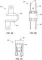
- FIG. 3A illustrates a relatively smaller device 20 with a smaller midsection height, while FIG.
- FIG. 3B illustrates a relatively larger sized device 20 with a greater midsection height than that of the device 20 of FIG. 3A
- FIG. 3C illustrates an even larger sized device 20 with an even greater midsection height than that of the device of FIGS. 3A and 3B .
- the lateral walls 36 of different bodies 22 may be provided at differing locations along the length of the inferior section 32 or superior section 34.
- the pair of lateral walls 36 may be staggered so that stacking of the device 20 at different, adjacent levels of the spine is possible. The surgeon can thus select a suitably shaped and sized main body 22 depending on the particular vertebral level to be supported and the anatomy of the patient.
- the lateral walls 36 may also be adjustable with respect to the main body 22.
- the lateral walls 36 may be formed of a malleable material such that, after implantation, the surgeon may compress the lateral walls 36 together to reduce the gap between the lateral walls 36, thereby securely fixing the main body 22 to a spinous process seated therein.
- the lateral walls 36 may be spread apart to facilitate insertion. The lateral walls 36 may be compressed or spread apart, for example, using surgical pliers or forceps (not shown).
- the device 20 can also comprise a U-shaped implant with a single pair of lateral walls 36.
- Such devices may be used at the L5-S1 vertebral level.
- the device 20 may include a single pair of lateral walls 36 configured to engage the spinous process and lamina of the L5 vertebra.
- the device 20 may include a mechanism for securing the inferior section 32 to the sacrum.
- the main body 22 may be formed from a medical grade metal such as titanium or a titanium alloy.
- the main body 22 may also be formed from a variety of other materials, such as stainless steel, cobalt chrome, ceramics, and/or polymeric materials, such as ultra-high molecular-weight polyethylene (UHMWPE) and polyetheretherketone (PEEK), either alone or in combination with other suitable materials.
- UHMWPE ultra-high molecular-weight polyethylene
- PEEK polyetheretherketone
- the device 20 may include a number of surface modifications.
- the main body 20 may include surface alterations that may facilitate tissue attachment, bonding, or fixation. These surface alterations may include protrusions, ridges, fins, teeth, barbs, beads, surface roughening, or the addition of bioactive agents to one or more sections of the device 20.
- the device 20 may include one or more ridges 40 for securing the device 20 to bone and/or soft tissue. As shown, the ridges 40 may be located on the main body 22, such as on the external surface of the inferior section 32 and/or superior section 34.
- the ridges 40 may extend in a generally horizontal direction. One ridge or a series of ridges 40 may be provided. Alternatively, or in addition, the ridges 40 may be located on an inner surface of the lateral walls 36. The ridges 40 may help the main body 22 securely engage connective tissue or a bony surface of a vertebra, such as the spinous process of the vertebra.
- the device 20 may also include roughened or porous surfaces.
- the roughened or porous surfaces may enhance attachment between implant surfaces and bone.
- some porous surfaces may facilitate tissue ingrowth to form a biological bond between sections of the device 20 and the surrounding bone and/or soft tissue. Roughened or porous surfaces may be included on any portion of the device 20.
- the surface of the device 20 may also include biologically active agents. These agents may include osteogenic factors to further facilitate bonding between components of the device 20 and the surrounding bone and/or soft tissue. Further, the device 20 may include therapeutic agents such as antibiotics, steroids, anti-thrombotic agents, anti-inflammatory drugs, and/or analgesic agents. In one embodiment, the biologically active agent may be contained in a coating on the device 20. Alternatively, or in addition, the device 20 may be porous, and the biologically active agent may be contained in the pores of the device 20. The biologically active agent may be, for example, bone morphogenic protein (BMP) for modulating cartilage or bone growth.
- BMP bone morphogenic protein
- the interspinous device 20 may be used in cases where rigid stability of a spinal segment is desired.
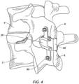
- the device 20 may be configured as a fusion promoting device, and may include apertures 50 on the lateral walls 36 for receiving a bone fastener 60 such as a bone screw, ligament, band, tie, or other similar fastening mechanism to fix the brackets 36 to the spinous processes, as illustrated in FIG. 4 .
- the inferior section 32 and superior section 34 each include a slot or cutout portion 46 at their free ends so as to form a 3-sided, U-shaped wall 48 within each of the inferior and superior sections 32, 34, as shown in FIG. 2C .
- This U-shaped wall 48 serves as a receiving slot for holding a fusion promoting component 80, such as a bone graft, or bone substitute, as shown in FIG. 4 .
- the body 22 may be configured to be rigid, i.e., not flexible and/or bendable, such as, for example, by providing an unextendable and/or uncompressible midsection 30. Such features enable rigid, fusion promoting securement of the device 20 to the adjacent vertebrae and their spinous processes.
- the fusion promoting component 80 may be shaped as a semi-solid or solid block that can be slid into the slots 46.
- the component 80 may be held by a friction fit or interference fit, or may be shaped to have a complementary fit with the shape of the receiving slots 46.
- the slots 46 have a gripping surface that comprises one or more vertically extending teeth 70 to hold the component 80 securely in position, and prevent slippage in the posterior direction. These one or more vertically extending teeth 70 act to enhance the ability of the device 20 to retain the fusion promoting component 80, while also providing the device 20 with the ability to allow a ratcheting-like insertion of the fusion promoting component 80 into the receiving slots 46.
- the one or more vertically extending teeth 70 may be uniformly spaced. However, it is understood that the extending teeth 70 may also be non-uniformly spaced, or provided as a pattern such as a group of teeth 70 clustered in discreet regions along the gripping surface of the U-shaped slot 46.
- the device 20 may be placed between adjacent vertebrae 2, 4 such that the spinous processes 6, 8 of the vertebrae are received within the stirrups 38 of the device 20.
- the device 20 is configured to seat interlaminarly as well as be interspinous, as shown.
- Bone fasteners 60 may be used to secure the device 20 to the vertebrae 2, 4 by securing the lateral walls 36 to the spinous processes 6, 8.
- a fusion promoting component 80 such as for example a bone graft plug or block, or bone substitute like putty or paste, may be inserted into the receiving slots 46 of the inferior and superior sections 32.
- the device 20 and the fusion promoting component 80 work in tandem to support and stabilize the spinal segment, providing rigid fixation of the vertebrae together.
Landscapes
- Health & Medical Sciences (AREA)
- Orthopedic Medicine & Surgery (AREA)
- Life Sciences & Earth Sciences (AREA)
- Neurology (AREA)
- Surgery (AREA)
- Heart & Thoracic Surgery (AREA)
- Engineering & Computer Science (AREA)
- Biomedical Technology (AREA)
- Nuclear Medicine, Radiotherapy & Molecular Imaging (AREA)
- Medical Informatics (AREA)
- Molecular Biology (AREA)
- Animal Behavior & Ethology (AREA)
- General Health & Medical Sciences (AREA)
- Public Health (AREA)
- Veterinary Medicine (AREA)
- Prostheses (AREA)
- Surgical Instruments (AREA)
Claims (11)
- Interspinöse Stabilisierungs- und Fusionsvorrichtung (20), umfassend:einen Hauptkörper (22), der für eine interlaminare Platzierung zwischen benachbarten Wirbeln (2, 4) konfiguriert ist, wobei der Hauptkörper (22) einen Mittelabschnitt (30) und einen unteren Abschnitt (32) und einen oberen Abschnitt (34) aufweist, die sich vom Mittelabschnitt (30) aus erstrecken, um einen U-förmigen Körper zu bilden, wobei sowohl der untere als auch der obere Abschnitt (32, 34), ein Paar von seitlichen Wänden (36) aufweist, die sich davon erstrecken, um einen Bügel (38) zur Aufnahme eines Dornfortsatzes (6, 8) zu bilden, dadurch gekennzeichnet, dass die unteren und oberen Abschnitte (32, 34) ferner einen ausgeschnittenen Abschnitt aufweisen, um einen U-förmigen Aufnahmeschlitz (46) zu bilden, wobei der Aufnahmeschlitz (46) drei Wände (48) aufweist, die um eine Öffnung herum gebildet sind, wobei die Öffnung in die posteriore Richtung weist,wobei jeder der Aufnahmeschlitze (46) eine Greiffläche mit einem oder mehreren sich vertikal erstreckenden Zähnen (70) an einem Paar gegenüberliegender Wände aufweist,wobei die Zähne so konfiguriert sind, dass sie eine ratschenartige, in der Tiefe einstellbare Platzierung einer fusionsfördernden Komponente (80) innerhalb des Aufnahmeschlitzes (46) ermöglichen.
- Vorrichtung nach Anspruch 1, wobei die Seitenwände (36) Öffnungen (50) zur Aufnahme einer Knochenbefestigungsvorrichtung (60) aufweisen.
- Vorrichtung nach Anspruch 1, wobei der Hauptkörper (22) eine oder mehrere horizontal verlaufende Rippen (40) zur Verbesserung der Knochenbefestigung aufweist.
- Vorrichtung nach Anspruch 3, wobei sich die eine oder die mehreren horizontal verlaufenden Rippen (40) auf einer Außenfläche des unteren und oberen Abschnitts (32, 34) befinden.
- Vorrichtung nach Anspruch 3, wobei sich die eine oder die mehreren horizontal verlaufenden Rippen (40) an den Seitenwänden (36) befinden.
- Vorrichtung nach Anspruch 1, wobei die Greiffläche jedes der Aufnahmeschlitze (46) eine Vielzahl von sich vertikal erstreckenden Zähnen (70) aufweist, die gleichmäßig voneinander beabstandet sind.
- Vorrichtung nach Anspruch 1, bei der die Greiffläche jedes der Aufnahmeschlitze (46) eine Vielzahl von sich vertikal erstreckenden Zähnen (70) umfasst, die in diskreten Bereichen in einem Muster gruppiert sind.
- Ein Wirbelsäulenstabilisierungssystem, umfassend:eine interspinöse Stabilisierungs- und Fusionsvorrichtung (20) nach einem der Ansprüche 1 bis 8; undeine die Knochenfusion fördernde Komponente (80), die zum Einsetzen in den Aufnahmeschlitz (46) konfiguriert ist.
- System nach Anspruch 8, wobei die Seitenwände (36) ferner Öffnungen (50) zur Aufnahme einer Knochenbefestigungsvorrichtung (60) aufweisen.
- System nach Anspruch 9, das außerdem eine Knochenbefestigungsvorrichtung (60) zur Platzierung durch die Öffnungen (50) der Seitenwände (36) umfasst.
- System nach Anspruch 8, wobei die fusionsfördernde Komponente (80) eine Knochentransplantat- oder eine Knochenersatzkomponente umfasst.
Applications Claiming Priority (2)
| Application Number | Priority Date | Filing Date | Title |
|---|---|---|---|
| US201562199433P | 2015-07-31 | 2015-07-31 | |
| PCT/US2016/044852 WO2017023800A1 (en) | 2015-07-31 | 2016-07-29 | Interspinous stabilization and fusion device |
Publications (3)
| Publication Number | Publication Date |
|---|---|
| EP3328302A1 EP3328302A1 (de) | 2018-06-06 |
| EP3328302A4 EP3328302A4 (de) | 2019-04-17 |
| EP3328302B1 true EP3328302B1 (de) | 2023-06-14 |
Family
ID=57886233
Family Applications (1)
| Application Number | Title | Priority Date | Filing Date |
|---|---|---|---|
| EP16833643.6A Active EP3328302B1 (de) | 2015-07-31 | 2016-07-29 | Interspinale stabilisierungs- und fusionsvorrichtung |
Country Status (7)
| Country | Link |
|---|---|
| US (2) | US10398478B2 (de) |
| EP (1) | EP3328302B1 (de) |
| CN (1) | CN108366816A (de) |
| AU (1) | AU2016303648B2 (de) |
| ES (1) | ES2955469T3 (de) |
| HK (1) | HK1259385A1 (de) |
| WO (1) | WO2017023800A1 (de) |
Families Citing this family (17)
| Publication number | Priority date | Publication date | Assignee | Title |
|---|---|---|---|---|
| US11213325B2 (en) * | 2013-03-15 | 2022-01-04 | Jcbd, Llc | Spinal stabilization system with adjustable interlaminar devices |
| EP3328302B1 (de) * | 2015-07-31 | 2023-06-14 | Paradigm Spine, LLC. | Interspinale stabilisierungs- und fusionsvorrichtung |
| EP3422973B1 (de) * | 2016-03-03 | 2023-04-19 | Paradigm Spine, LLC. | Instrumente für interspinale oder interlaminare stabilisierungsvorrichtungen |
| EP4368128A3 (de) | 2016-09-07 | 2024-07-17 | Vertos Medical, Inc. | Verfahren und instrumente zur perkutanen seitlichen resektion von aussparungen |
| US10828071B2 (en) * | 2017-02-21 | 2020-11-10 | Avery M. Jackson | Hinged anterior cervical locking plate system |
| US11931269B2 (en) | 2017-07-10 | 2024-03-19 | Xtant Medical, Inc. | Delivery systems for interspinous, interlaminar stabilization devices and methods of use |
| CN109009381A (zh) * | 2018-07-17 | 2018-12-18 | 常州集硕医疗器械有限公司 | 棘突间固定融合装置 |
| CN109998658B (zh) * | 2019-05-14 | 2020-11-17 | 首都医科大学附属北京友谊医院 | 一种作用于椎板间及棘突间的动态稳定系统 |
| CA3147517A1 (en) | 2019-08-21 | 2021-02-25 | Cheng-Lun SOO | Interspinous-interlaminar stabilization systems and methods |
| EP4054452A1 (de) | 2019-11-07 | 2022-09-14 | Freedom Innovations, LLC | Implantierbares modulares orthopädisches plattensystem |
| US12011360B2 (en) | 2021-10-22 | 2024-06-18 | Linares Spinal Devices, Llc | Expandable spinal jack for installation between upper and lower succeeding superior articular processes |
| US12137947B2 (en) | 2021-11-02 | 2024-11-12 | Linares Spinal Devices, Llc | Expandable spinal jack for installation between upper and lower succeeding superior articular processes |
| US11432937B1 (en) | 2021-11-02 | 2022-09-06 | Linares Medical Devices, Llc | Expandable spinal jack for installation between upper and lower succeeding superior articular processes |
| TWI819504B (zh) * | 2022-02-25 | 2023-10-21 | 寶億生技股份有限公司 | 棘突間撐開固定裝置及其穩定裝置 |
| WO2023245144A1 (en) | 2022-06-16 | 2023-12-21 | Vertos Medical, Inc. | Integrated instrument assembly |
| US12575863B2 (en) | 2023-02-13 | 2026-03-17 | FloSpine, LLC | Interspinous-interlaminar stabilization systems and methods |
| CN118319567B (zh) * | 2024-04-08 | 2025-04-25 | 首都医科大学宣武医院 | 一种椎板非融合固定装置 |
Family Cites Families (53)
| Publication number | Priority date | Publication date | Assignee | Title |
|---|---|---|---|---|
| US5496318A (en) | 1993-01-08 | 1996-03-05 | Advanced Spine Fixation Systems, Inc. | Interspinous segmental spine fixation device |
| FR2722980B1 (fr) * | 1994-07-26 | 1996-09-27 | Samani Jacques | Implant vertebral inter-epineux |
| FR2774581B1 (fr) | 1998-02-10 | 2000-08-11 | Dimso Sa | Stabilisateur interepineux a fixer a des apophyses epineuses de deux vertebres |
| EP1578314B1 (de) | 2003-11-07 | 2007-05-30 | Impliant Ltd. | Wirbelsäulenprothesen |
| US8636802B2 (en) | 2004-03-06 | 2014-01-28 | DePuy Synthes Products, LLC | Dynamized interspinal implant |
| US7763073B2 (en) | 2004-03-09 | 2010-07-27 | Depuy Spine, Inc. | Posterior process dynamic spacer |
| US20060015181A1 (en) | 2004-07-19 | 2006-01-19 | Biomet Merck France (50% Interest) | Interspinous vertebral implant |
| US7862590B2 (en) | 2005-04-08 | 2011-01-04 | Warsaw Orthopedic, Inc. | Interspinous process spacer |
| EP1871253B1 (de) | 2005-04-08 | 2015-09-16 | Paradigm Spine, LLC | Interspinöse wirbel- und lumbosakral-stabilisierungsvorrichtungen |
| US7727233B2 (en) | 2005-04-29 | 2010-06-01 | Warsaw Orthopedic, Inc. | Spinous process stabilization devices and methods |
| US20120303127A1 (en) * | 2005-05-06 | 2012-11-29 | Titan Spine, Llc | Implants having internal features for graft retention and load transfer between implant and vertebrae |
| US20130296939A1 (en) | 2005-11-22 | 2013-11-07 | Richard Perkins | Adjustable spinous process spacer device and method of treating spinal disorders |
| EP1968466A2 (de) | 2005-12-19 | 2008-09-17 | M. S. Abdou | Vorrichtungen zur intervertebralen platzierung einer orthopädischen vorrichtung |
| US8083795B2 (en) | 2006-01-18 | 2011-12-27 | Warsaw Orthopedic, Inc. | Intervertebral prosthetic device for spinal stabilization and method of manufacturing same |
| US7871426B2 (en) | 2006-03-21 | 2011-01-18 | Spinefrontier, LLS | Spinous process fixation device |
| CN101594836A (zh) | 2007-01-23 | 2009-12-02 | 生物智慧株式会社 | 在脊椎棘突的外科手术中所使用的隔片 |
| US8568453B2 (en) | 2007-01-29 | 2013-10-29 | Samy Abdou | Spinal stabilization systems and methods of use |
| WO2008106140A2 (en) | 2007-02-26 | 2008-09-04 | Abdou M Samy | Spinal stabilization systems and methods of use |
| US9173686B2 (en) | 2007-05-09 | 2015-11-03 | Ebi, Llc | Interspinous implant |
| US9381047B2 (en) * | 2007-05-09 | 2016-07-05 | Ebi, Llc | Interspinous implant |
| EP1994900A1 (de) | 2007-05-22 | 2008-11-26 | Flexismed SA | Interspinales Implantat für Wirbelsäule |
| US20090005873A1 (en) | 2007-06-29 | 2009-01-01 | Michael Andrew Slivka | Spinous Process Spacer Hammock |
| WO2009086397A2 (en) | 2007-12-28 | 2009-07-09 | Osteomed Spine, Inc. | Bone tissue fixation device and method |
| JP2011516122A (ja) | 2008-03-28 | 2011-05-26 | スパイノロジー インコーポレイテッド | 棘突起の融合方法及び機器 |
| BRPI0801855A2 (pt) | 2008-04-25 | 2009-12-29 | Gm Dos Reis Jr | dispositivo interespinhoso |
| US8206420B2 (en) | 2008-08-08 | 2012-06-26 | Alphatec Spine, Inc | Spinous process device and method of use |
| CN102137628A (zh) | 2008-08-28 | 2011-07-27 | 斯恩蒂斯有限公司 | 骨源性椎间间隔物 |
| US8236031B2 (en) | 2009-01-26 | 2012-08-07 | Life Spine, Inc. | Flexible and static interspinous/inter-laminar spinal spacers |
| US8303629B1 (en) | 2009-03-19 | 2012-11-06 | Abdou M Samy | Spinous process fusion and orthopedic implants and methods |
| US10517650B2 (en) | 2009-05-01 | 2019-12-31 | Spinal Kinetics, Inc. | Spinal stabilization devices, systems, and methods |
| JP2012531263A (ja) | 2009-06-23 | 2012-12-10 | オステオメド リミテッド ライアビリティ カンパニー | 骨組織クランプ |
| US8998954B2 (en) | 2009-08-03 | 2015-04-07 | Life Spine, Inc. | Spinous process spacer |
| US8262697B2 (en) | 2010-01-14 | 2012-09-11 | X-Spine Systems, Inc. | Modular interspinous fixation system and method |
| US20110184468A1 (en) | 2010-01-28 | 2011-07-28 | Warsaw Orthopedic, Inc., An Indiana Corporation | Spinous process fusion plate with osteointegration insert |
| CA2787847A1 (en) | 2010-03-04 | 2011-09-09 | Synthes Usa, Llc | Expandable lamina spinal fusion implant |
| US20110264221A1 (en) | 2010-04-24 | 2011-10-27 | Custom Spine, Inc. | Interspinous Fusion Device and Method |
| US8790373B2 (en) | 2010-07-15 | 2014-07-29 | Kamran Aflatoon | Dynamic inter-spinous process spacer |
| US9204907B2 (en) | 2010-07-15 | 2015-12-08 | Kamran Aflatoon | Dynamic inter-spinous process spacer |
| FR2964850B1 (fr) | 2010-09-17 | 2013-08-09 | Spineart Sa | Systeme de pincement d'epineuses et ses applications |
| US8603143B2 (en) | 2010-12-05 | 2013-12-10 | James C. Robinson | Spinous process fixation apparatus |
| US8603142B2 (en) | 2010-12-05 | 2013-12-10 | James C. Robinson | Spinous process fixation apparatus and method |
| US8876866B2 (en) | 2010-12-13 | 2014-11-04 | Globus Medical, Inc. | Spinous process fusion devices and methods thereof |
| CA2829661C (en) * | 2011-02-06 | 2019-05-07 | Paradigm Spine, Llc | Translaminar interspinous stabilization system |
| WO2012154265A1 (en) | 2011-02-22 | 2012-11-15 | Simpirica Spine, Inc. | Spinous process cerclage for bone graft containment |
| WO2012125534A1 (en) | 2011-03-11 | 2012-09-20 | IINN, Inc. | Intra spinous process and method of bone graft placement |
| FR2977139B1 (fr) | 2011-06-30 | 2014-08-22 | Ldr Medical | Implant inter-epineux et instrument d’implantation |
| WO2013052496A2 (en) | 2011-10-03 | 2013-04-11 | In Queue Innovations, Llc | Interspinous process fusion device and method of use |
| EP2800532B1 (de) | 2012-01-05 | 2019-12-11 | Lanx, Inc. | Teleskopische interspinale fixiervorrichtung |
| ES2739197T3 (es) * | 2012-02-17 | 2020-01-29 | Univ Toledo | Dispositivo multifuncional híbrido de artrodesis interespinosa posterior |
| CA2869769C (en) | 2012-04-17 | 2023-09-26 | Aurora Spine, Llc | A dynamic and non-dynamic interspinous fusion implant and bone growth stimulation system |
| US8771368B2 (en) | 2012-04-24 | 2014-07-08 | William F. McKay | Interspinous bone implant device |
| US8906065B2 (en) | 2012-10-22 | 2014-12-09 | Spectrum Spine Ip Holdings, Llc | Inter-spinous process device and method |
| EP3328302B1 (de) * | 2015-07-31 | 2023-06-14 | Paradigm Spine, LLC. | Interspinale stabilisierungs- und fusionsvorrichtung |
-
2016
- 2016-07-29 EP EP16833643.6A patent/EP3328302B1/de active Active
- 2016-07-29 HK HK19101753.4A patent/HK1259385A1/zh unknown
- 2016-07-29 AU AU2016303648A patent/AU2016303648B2/en active Active
- 2016-07-29 CN CN201680056216.7A patent/CN108366816A/zh active Pending
- 2016-07-29 ES ES16833643T patent/ES2955469T3/es active Active
- 2016-07-29 US US15/224,075 patent/US10398478B2/en active Active
- 2016-07-29 WO PCT/US2016/044852 patent/WO2017023800A1/en not_active Ceased
-
2019
- 2019-07-23 US US16/519,375 patent/US11141201B2/en active Active
Also Published As
| Publication number | Publication date |
|---|---|
| CN108366816A (zh) | 2018-08-03 |
| ES2955469T3 (es) | 2023-12-01 |
| HK1259385A1 (zh) | 2019-11-29 |
| US20170027619A1 (en) | 2017-02-02 |
| EP3328302A1 (de) | 2018-06-06 |
| WO2017023800A1 (en) | 2017-02-09 |
| US10398478B2 (en) | 2019-09-03 |
| US20200015863A1 (en) | 2020-01-16 |
| AU2016303648B2 (en) | 2021-03-25 |
| WO2017023800A9 (en) | 2018-02-01 |
| EP3328302A4 (de) | 2019-04-17 |
| US11141201B2 (en) | 2021-10-12 |
| AU2016303648A1 (en) | 2018-03-15 |
Similar Documents
| Publication | Publication Date | Title |
|---|---|---|
| US11141201B2 (en) | Interspinous stabilization and fusion device | |
| US9968381B2 (en) | Translaminar interspinous stabilization system | |
| EP2101664B1 (de) | Zwischenlaminae-interspinöse wirbel-stabilizierungsvorrichtung | |
| EP2992844B1 (de) | Interspinale wirbel- und lumbosakralstabilisierungsvorrichtungen | |
| US10278745B2 (en) | Interlaminar, interspinous stabilization devices for the cervical spine | |
| AU2016235005B2 (en) | Interlaminar-Interspinous Vertebral Stabilization System | |
| AU2014200937B2 (en) | Interlaminar-Interspinous Vertebral Stabilization System | |
| HK1192701B (en) | Translaminar interspinous stabilization system |
Legal Events
| Date | Code | Title | Description |
|---|---|---|---|
| STAA | Information on the status of an ep patent application or granted ep patent |
Free format text: STATUS: THE INTERNATIONAL PUBLICATION HAS BEEN MADE |
|
| PUAI | Public reference made under article 153(3) epc to a published international application that has entered the european phase |
Free format text: ORIGINAL CODE: 0009012 |
|
| STAA | Information on the status of an ep patent application or granted ep patent |
Free format text: STATUS: REQUEST FOR EXAMINATION WAS MADE |
|
| 17P | Request for examination filed |
Effective date: 20180228 |
|
| AK | Designated contracting states |
Kind code of ref document: A1 Designated state(s): AL AT BE BG CH CY CZ DE DK EE ES FI FR GB GR HR HU IE IS IT LI LT LU LV MC MK MT NL NO PL PT RO RS SE SI SK SM TR |
|
| AX | Request for extension of the european patent |
Extension state: BA ME |
|
| RIN1 | Information on inventor provided before grant (corrected) |
Inventor name: EISEN, GUNTMAR Inventor name: GANTER, DETLEV Inventor name: ECKHOF, STEPHAN |
|
| DAV | Request for validation of the european patent (deleted) | ||
| DAX | Request for extension of the european patent (deleted) | ||
| RAP1 | Party data changed (applicant data changed or rights of an application transferred) |
Owner name: PARADIGM SPINE, LLC. |
|
| A4 | Supplementary search report drawn up and despatched |
Effective date: 20190314 |
|
| RIC1 | Information provided on ipc code assigned before grant |
Ipc: A61B 17/70 20060101AFI20190308BHEP Ipc: A61B 17/56 20060101ALI20190308BHEP Ipc: A61B 17/68 20060101ALI20190308BHEP |
|
| GRAP | Despatch of communication of intention to grant a patent |
Free format text: ORIGINAL CODE: EPIDOSNIGR1 |
|
| STAA | Information on the status of an ep patent application or granted ep patent |
Free format text: STATUS: GRANT OF PATENT IS INTENDED |
|
| INTG | Intention to grant announced |
Effective date: 20230110 |
|
| GRAS | Grant fee paid |
Free format text: ORIGINAL CODE: EPIDOSNIGR3 |
|
| GRAA | (expected) grant |
Free format text: ORIGINAL CODE: 0009210 |
|
| STAA | Information on the status of an ep patent application or granted ep patent |
Free format text: STATUS: THE PATENT HAS BEEN GRANTED |
|
| AK | Designated contracting states |
Kind code of ref document: B1 Designated state(s): AL AT BE BG CH CY CZ DE DK EE ES FI FR GB GR HR HU IE IS IT LI LT LU LV MC MK MT NL NO PL PT RO RS SE SI SK SM TR |
|
| REG | Reference to a national code |
Ref country code: CH Ref legal event code: EP |
|
| REG | Reference to a national code |
Ref country code: DE Ref legal event code: R096 Ref document number: 602016080373 Country of ref document: DE |
|
| REG | Reference to a national code |
Ref country code: AT Ref legal event code: REF Ref document number: 1578657 Country of ref document: AT Kind code of ref document: T Effective date: 20230715 |
|
| REG | Reference to a national code |
Ref country code: DE Ref legal event code: R081 Ref document number: 602016080373 Country of ref document: DE Owner name: SURGALIGN SPV, INC., BELGRADE, US Free format text: FORMER OWNER: PARADIGM SPINE, LLC, NEW YORK, NY, US |
|
| P01 | Opt-out of the competence of the unified patent court (upc) registered |
Effective date: 20230718 |
|
| RAP2 | Party data changed (patent owner data changed or rights of a patent transferred) |
Owner name: SURGALIGN SPV, INC. |
|
| REG | Reference to a national code |
Ref country code: LT Ref legal event code: MG9D |
|
| REG | Reference to a national code |
Ref country code: NL Ref legal event code: MP Effective date: 20230614 |
|
| PG25 | Lapsed in a contracting state [announced via postgrant information from national office to epo] |
Ref country code: SE Free format text: LAPSE BECAUSE OF FAILURE TO SUBMIT A TRANSLATION OF THE DESCRIPTION OR TO PAY THE FEE WITHIN THE PRESCRIBED TIME-LIMIT Effective date: 20230614 Ref country code: NO Free format text: LAPSE BECAUSE OF FAILURE TO SUBMIT A TRANSLATION OF THE DESCRIPTION OR TO PAY THE FEE WITHIN THE PRESCRIBED TIME-LIMIT Effective date: 20230914 |
|
| REG | Reference to a national code |
Ref country code: AT Ref legal event code: MK05 Ref document number: 1578657 Country of ref document: AT Kind code of ref document: T Effective date: 20230614 |
|
| PG25 | Lapsed in a contracting state [announced via postgrant information from national office to epo] |
Ref country code: RS Free format text: LAPSE BECAUSE OF FAILURE TO SUBMIT A TRANSLATION OF THE DESCRIPTION OR TO PAY THE FEE WITHIN THE PRESCRIBED TIME-LIMIT Effective date: 20230614 Ref country code: NL Free format text: LAPSE BECAUSE OF FAILURE TO SUBMIT A TRANSLATION OF THE DESCRIPTION OR TO PAY THE FEE WITHIN THE PRESCRIBED TIME-LIMIT Effective date: 20230614 Ref country code: LV Free format text: LAPSE BECAUSE OF FAILURE TO SUBMIT A TRANSLATION OF THE DESCRIPTION OR TO PAY THE FEE WITHIN THE PRESCRIBED TIME-LIMIT Effective date: 20230614 Ref country code: LT Free format text: LAPSE BECAUSE OF FAILURE TO SUBMIT A TRANSLATION OF THE DESCRIPTION OR TO PAY THE FEE WITHIN THE PRESCRIBED TIME-LIMIT Effective date: 20230614 Ref country code: HR Free format text: LAPSE BECAUSE OF FAILURE TO SUBMIT A TRANSLATION OF THE DESCRIPTION OR TO PAY THE FEE WITHIN THE PRESCRIBED TIME-LIMIT Effective date: 20230614 Ref country code: GR Free format text: LAPSE BECAUSE OF FAILURE TO SUBMIT A TRANSLATION OF THE DESCRIPTION OR TO PAY THE FEE WITHIN THE PRESCRIBED TIME-LIMIT Effective date: 20230915 |
|
| REG | Reference to a national code |
Ref country code: ES Ref legal event code: FG2A Ref document number: 2955469 Country of ref document: ES Kind code of ref document: T3 Effective date: 20231201 |
|
| REG | Reference to a national code |
Ref country code: GB Ref legal event code: 732E Free format text: REGISTERED BETWEEN 20231123 AND 20231129 |
|
| PG25 | Lapsed in a contracting state [announced via postgrant information from national office to epo] |
Ref country code: FI Free format text: LAPSE BECAUSE OF FAILURE TO SUBMIT A TRANSLATION OF THE DESCRIPTION OR TO PAY THE FEE WITHIN THE PRESCRIBED TIME-LIMIT Effective date: 20230614 |
|
| PG25 | Lapsed in a contracting state [announced via postgrant information from national office to epo] |
Ref country code: SK Free format text: LAPSE BECAUSE OF FAILURE TO SUBMIT A TRANSLATION OF THE DESCRIPTION OR TO PAY THE FEE WITHIN THE PRESCRIBED TIME-LIMIT Effective date: 20230614 |
|
| PG25 | Lapsed in a contracting state [announced via postgrant information from national office to epo] |
Ref country code: IS Free format text: LAPSE BECAUSE OF FAILURE TO SUBMIT A TRANSLATION OF THE DESCRIPTION OR TO PAY THE FEE WITHIN THE PRESCRIBED TIME-LIMIT Effective date: 20231014 |
|
| PG25 | Lapsed in a contracting state [announced via postgrant information from national office to epo] |
Ref country code: SM Free format text: LAPSE BECAUSE OF FAILURE TO SUBMIT A TRANSLATION OF THE DESCRIPTION OR TO PAY THE FEE WITHIN THE PRESCRIBED TIME-LIMIT Effective date: 20230614 Ref country code: SK Free format text: LAPSE BECAUSE OF FAILURE TO SUBMIT A TRANSLATION OF THE DESCRIPTION OR TO PAY THE FEE WITHIN THE PRESCRIBED TIME-LIMIT Effective date: 20230614 Ref country code: RO Free format text: LAPSE BECAUSE OF FAILURE TO SUBMIT A TRANSLATION OF THE DESCRIPTION OR TO PAY THE FEE WITHIN THE PRESCRIBED TIME-LIMIT Effective date: 20230614 Ref country code: PT Free format text: LAPSE BECAUSE OF FAILURE TO SUBMIT A TRANSLATION OF THE DESCRIPTION OR TO PAY THE FEE WITHIN THE PRESCRIBED TIME-LIMIT Effective date: 20231016 Ref country code: IS Free format text: LAPSE BECAUSE OF FAILURE TO SUBMIT A TRANSLATION OF THE DESCRIPTION OR TO PAY THE FEE WITHIN THE PRESCRIBED TIME-LIMIT Effective date: 20231014 Ref country code: EE Free format text: LAPSE BECAUSE OF FAILURE TO SUBMIT A TRANSLATION OF THE DESCRIPTION OR TO PAY THE FEE WITHIN THE PRESCRIBED TIME-LIMIT Effective date: 20230614 Ref country code: CZ Free format text: LAPSE BECAUSE OF FAILURE TO SUBMIT A TRANSLATION OF THE DESCRIPTION OR TO PAY THE FEE WITHIN THE PRESCRIBED TIME-LIMIT Effective date: 20230614 Ref country code: AT Free format text: LAPSE BECAUSE OF FAILURE TO SUBMIT A TRANSLATION OF THE DESCRIPTION OR TO PAY THE FEE WITHIN THE PRESCRIBED TIME-LIMIT Effective date: 20230614 |
|
| PG25 | Lapsed in a contracting state [announced via postgrant information from national office to epo] |
Ref country code: PL Free format text: LAPSE BECAUSE OF FAILURE TO SUBMIT A TRANSLATION OF THE DESCRIPTION OR TO PAY THE FEE WITHIN THE PRESCRIBED TIME-LIMIT Effective date: 20230614 |
|
| REG | Reference to a national code |
Ref country code: CH Ref legal event code: PL |
|
| PG25 | Lapsed in a contracting state [announced via postgrant information from national office to epo] |
Ref country code: MC Free format text: LAPSE BECAUSE OF FAILURE TO SUBMIT A TRANSLATION OF THE DESCRIPTION OR TO PAY THE FEE WITHIN THE PRESCRIBED TIME-LIMIT Effective date: 20230614 |
|
| REG | Reference to a national code |
Ref country code: DE Ref legal event code: R097 Ref document number: 602016080373 Country of ref document: DE |
|
| REG | Reference to a national code |
Ref country code: BE Ref legal event code: MM Effective date: 20230731 |
|
| PG25 | Lapsed in a contracting state [announced via postgrant information from national office to epo] |
Ref country code: LU Free format text: LAPSE BECAUSE OF NON-PAYMENT OF DUE FEES Effective date: 20230729 |
|
| PG25 | Lapsed in a contracting state [announced via postgrant information from national office to epo] |
Ref country code: MC Free format text: LAPSE BECAUSE OF FAILURE TO SUBMIT A TRANSLATION OF THE DESCRIPTION OR TO PAY THE FEE WITHIN THE PRESCRIBED TIME-LIMIT Effective date: 20230614 Ref country code: LU Free format text: LAPSE BECAUSE OF NON-PAYMENT OF DUE FEES Effective date: 20230729 |
|
| PLBE | No opposition filed within time limit |
Free format text: ORIGINAL CODE: 0009261 |
|
| STAA | Information on the status of an ep patent application or granted ep patent |
Free format text: STATUS: NO OPPOSITION FILED WITHIN TIME LIMIT |
|
| REG | Reference to a national code |
Ref country code: IE Ref legal event code: MM4A |
|
| PG25 | Lapsed in a contracting state [announced via postgrant information from national office to epo] |
Ref country code: DK Free format text: LAPSE BECAUSE OF FAILURE TO SUBMIT A TRANSLATION OF THE DESCRIPTION OR TO PAY THE FEE WITHIN THE PRESCRIBED TIME-LIMIT Effective date: 20230614 Ref country code: CH Free format text: LAPSE BECAUSE OF NON-PAYMENT OF DUE FEES Effective date: 20230731 |
|
| PG25 | Lapsed in a contracting state [announced via postgrant information from national office to epo] |
Ref country code: SI Free format text: LAPSE BECAUSE OF FAILURE TO SUBMIT A TRANSLATION OF THE DESCRIPTION OR TO PAY THE FEE WITHIN THE PRESCRIBED TIME-LIMIT Effective date: 20230614 |
|
| 26N | No opposition filed |
Effective date: 20240315 |
|
| PG25 | Lapsed in a contracting state [announced via postgrant information from national office to epo] |
Ref country code: SI Free format text: LAPSE BECAUSE OF FAILURE TO SUBMIT A TRANSLATION OF THE DESCRIPTION OR TO PAY THE FEE WITHIN THE PRESCRIBED TIME-LIMIT Effective date: 20230614 Ref country code: BE Free format text: LAPSE BECAUSE OF NON-PAYMENT OF DUE FEES Effective date: 20230731 |
|
| PG25 | Lapsed in a contracting state [announced via postgrant information from national office to epo] |
Ref country code: IE Free format text: LAPSE BECAUSE OF NON-PAYMENT OF DUE FEES Effective date: 20230729 |
|
| PG25 | Lapsed in a contracting state [announced via postgrant information from national office to epo] |
Ref country code: IE Free format text: LAPSE BECAUSE OF NON-PAYMENT OF DUE FEES Effective date: 20230729 Ref country code: FR Free format text: LAPSE BECAUSE OF NON-PAYMENT OF DUE FEES Effective date: 20230814 |
|
| PG25 | Lapsed in a contracting state [announced via postgrant information from national office to epo] |
Ref country code: BG Free format text: LAPSE BECAUSE OF FAILURE TO SUBMIT A TRANSLATION OF THE DESCRIPTION OR TO PAY THE FEE WITHIN THE PRESCRIBED TIME-LIMIT Effective date: 20230614 |
|
| PG25 | Lapsed in a contracting state [announced via postgrant information from national office to epo] |
Ref country code: BG Free format text: LAPSE BECAUSE OF FAILURE TO SUBMIT A TRANSLATION OF THE DESCRIPTION OR TO PAY THE FEE WITHIN THE PRESCRIBED TIME-LIMIT Effective date: 20230614 |
|
| PGFP | Annual fee paid to national office [announced via postgrant information from national office to epo] |
Ref country code: GB Payment date: 20250619 Year of fee payment: 10 |
|
| PG25 | Lapsed in a contracting state [announced via postgrant information from national office to epo] |
Ref country code: CY Free format text: LAPSE BECAUSE OF FAILURE TO SUBMIT A TRANSLATION OF THE DESCRIPTION OR TO PAY THE FEE WITHIN THE PRESCRIBED TIME-LIMIT; INVALID AB INITIO Effective date: 20160729 |
|
| PG25 | Lapsed in a contracting state [announced via postgrant information from national office to epo] |
Ref country code: HU Free format text: LAPSE BECAUSE OF FAILURE TO SUBMIT A TRANSLATION OF THE DESCRIPTION OR TO PAY THE FEE WITHIN THE PRESCRIBED TIME-LIMIT; INVALID AB INITIO Effective date: 20160729 |
|
| PGFP | Annual fee paid to national office [announced via postgrant information from national office to epo] |
Ref country code: ES Payment date: 20250801 Year of fee payment: 10 |
|
| PGFP | Annual fee paid to national office [announced via postgrant information from national office to epo] |
Ref country code: DE Payment date: 20250620 Year of fee payment: 10 |
|
| PGFP | Annual fee paid to national office [announced via postgrant information from national office to epo] |
Ref country code: IT Payment date: 20250619 Year of fee payment: 10 |
|
| PG25 | Lapsed in a contracting state [announced via postgrant information from national office to epo] |
Ref country code: TR Free format text: LAPSE BECAUSE OF FAILURE TO SUBMIT A TRANSLATION OF THE DESCRIPTION OR TO PAY THE FEE WITHIN THE PRESCRIBED TIME-LIMIT Effective date: 20230614 |