EP3328282B1 - Bildgebungssystem und -verfahren - Google Patents
Bildgebungssystem und -verfahren Download PDFInfo
- Publication number
- EP3328282B1 EP3328282B1 EP16763593.7A EP16763593A EP3328282B1 EP 3328282 B1 EP3328282 B1 EP 3328282B1 EP 16763593 A EP16763593 A EP 16763593A EP 3328282 B1 EP3328282 B1 EP 3328282B1
- Authority
- EP
- European Patent Office
- Prior art keywords
- imager
- translation
- counterweight
- piston
- axis
- Prior art date
- Legal status (The legal status is an assumption and is not a legal conclusion. Google has not performed a legal analysis and makes no representation as to the accuracy of the status listed.)
- Active
Links
Images


Classifications
-
- A—HUMAN NECESSITIES
- A61—MEDICAL OR VETERINARY SCIENCE; HYGIENE
- A61B—DIAGNOSIS; SURGERY; IDENTIFICATION
- A61B6/00—Apparatus or devices for radiation diagnosis; Apparatus or devices for radiation diagnosis combined with radiation therapy equipment
- A61B6/02—Arrangements for diagnosis sequentially in different planes; Stereoscopic radiation diagnosis
- A61B6/03—Computed tomography [CT]
- A61B6/032—Transmission computed tomography [CT]
- A61B6/035—Mechanical aspects of CT
-
- A—HUMAN NECESSITIES
- A61—MEDICAL OR VETERINARY SCIENCE; HYGIENE
- A61B—DIAGNOSIS; SURGERY; IDENTIFICATION
- A61B6/00—Apparatus or devices for radiation diagnosis; Apparatus or devices for radiation diagnosis combined with radiation therapy equipment
- A61B6/02—Arrangements for diagnosis sequentially in different planes; Stereoscopic radiation diagnosis
- A61B6/03—Computed tomography [CT]
- A61B6/032—Transmission computed tomography [CT]
-
- A—HUMAN NECESSITIES
- A61—MEDICAL OR VETERINARY SCIENCE; HYGIENE
- A61B—DIAGNOSIS; SURGERY; IDENTIFICATION
- A61B6/00—Apparatus or devices for radiation diagnosis; Apparatus or devices for radiation diagnosis combined with radiation therapy equipment
- A61B6/04—Positioning of patients; Tiltable beds or the like
- A61B6/0478—Chairs
-
- A—HUMAN NECESSITIES
- A61—MEDICAL OR VETERINARY SCIENCE; HYGIENE
- A61B—DIAGNOSIS; SURGERY; IDENTIFICATION
- A61B6/00—Apparatus or devices for radiation diagnosis; Apparatus or devices for radiation diagnosis combined with radiation therapy equipment
- A61B6/10—Safety means specially adapted therefor
-
- A—HUMAN NECESSITIES
- A61—MEDICAL OR VETERINARY SCIENCE; HYGIENE
- A61B—DIAGNOSIS; SURGERY; IDENTIFICATION
- A61B6/00—Apparatus or devices for radiation diagnosis; Apparatus or devices for radiation diagnosis combined with radiation therapy equipment
- A61B6/44—Constructional features of apparatus for radiation diagnosis
- A61B6/4429—Constructional features of apparatus for radiation diagnosis related to the mounting of source units and detector units
- A61B6/4435—Constructional features of apparatus for radiation diagnosis related to the mounting of source units and detector units the source unit and the detector unit being coupled by a rigid structure
- A61B6/4447—Tiltable gantries
-
- A—HUMAN NECESSITIES
- A61—MEDICAL OR VETERINARY SCIENCE; HYGIENE
- A61B—DIAGNOSIS; SURGERY; IDENTIFICATION
- A61B6/00—Apparatus or devices for radiation diagnosis; Apparatus or devices for radiation diagnosis combined with radiation therapy equipment
- A61B6/44—Constructional features of apparatus for radiation diagnosis
- A61B6/4429—Constructional features of apparatus for radiation diagnosis related to the mounting of source units and detector units
- A61B6/447—Constructional features of apparatus for radiation diagnosis related to the mounting of source units and detector units the source unit or the detector unit being mounted to counterpoise or springs
-
- A—HUMAN NECESSITIES
- A61—MEDICAL OR VETERINARY SCIENCE; HYGIENE
- A61B—DIAGNOSIS; SURGERY; IDENTIFICATION
- A61B6/00—Apparatus or devices for radiation diagnosis; Apparatus or devices for radiation diagnosis combined with radiation therapy equipment
- A61B6/44—Constructional features of apparatus for radiation diagnosis
- A61B6/4476—Constructional features of apparatus for radiation diagnosis related to motor-assisted motion of the source unit
-
- A—HUMAN NECESSITIES
- A61—MEDICAL OR VETERINARY SCIENCE; HYGIENE
- A61N—ELECTROTHERAPY; MAGNETOTHERAPY; RADIATION THERAPY; ULTRASOUND THERAPY
- A61N5/00—Radiation therapy
- A61N5/10—X-ray therapy; Gamma-ray therapy; Particle-irradiation therapy
- A61N5/1048—Monitoring, verifying, controlling systems and methods
- A61N5/1049—Monitoring, verifying, controlling systems and methods for verifying the position of the patient with respect to the radiation beam
- A61N2005/1061—Monitoring, verifying, controlling systems and methods for verifying the position of the patient with respect to the radiation beam using an x-ray imaging system having a separate imaging source
-
- A—HUMAN NECESSITIES
- A61—MEDICAL OR VETERINARY SCIENCE; HYGIENE
- A61N—ELECTROTHERAPY; MAGNETOTHERAPY; RADIATION THERAPY; ULTRASOUND THERAPY
- A61N5/00—Radiation therapy
- A61N5/10—X-ray therapy; Gamma-ray therapy; Particle-irradiation therapy
- A61N5/1048—Monitoring, verifying, controlling systems and methods
- A61N5/1049—Monitoring, verifying, controlling systems and methods for verifying the position of the patient with respect to the radiation beam
- A61N2005/1063—Monitoring, verifying, controlling systems and methods for verifying the position of the patient with respect to the radiation beam maintaining the position when the patient is moved from an imaging to a therapy system
-
- A—HUMAN NECESSITIES
- A61—MEDICAL OR VETERINARY SCIENCE; HYGIENE
- A61N—ELECTROTHERAPY; MAGNETOTHERAPY; RADIATION THERAPY; ULTRASOUND THERAPY
- A61N5/00—Radiation therapy
- A61N5/10—X-ray therapy; Gamma-ray therapy; Particle-irradiation therapy
- A61N2005/1085—X-ray therapy; Gamma-ray therapy; Particle-irradiation therapy characterised by the type of particles applied to the patient
- A61N2005/1087—Ions; Protons
Definitions
- the invention relates generally to the field of imaging devices and in particular to an angled imaging system and method.
- Teletherapy is defined as a treatment methodology in which an irradiation source is at a distance from the body to be treated.
- X-rays and electron beams have long been used in teletherapy to treat various cancers.
- X-rays exhibit a linear energy transfer approaching an exponential attenuation function, and are therefore of minimal safe use for deeply embedded growths.
- the use of heavy particles, particularly hadrons and more particularly protons, in teletherapy has found increasing acceptance, due to the ability of heavy particles to penetrate to a specific depth without appreciably harming intervening tissue.
- the linear energy transfer of hadrons exhibits an inversed depth profile with a marked Bragg peak defined as the point at which the hadrons deposit most of their energy, and occurs at the end of the hadrons path.
- hadrons include a wide range of particles, practically, protons and various ions are most widely used in therapy. For clarity, this document will describe treatment as being accomplished with protons, however this is not meant to be limiting in any way.
- the charged protons or ions can be focused to a target volume of variable penetration depth. In this way the dose profile can be matched closely to the target volume with a high precision.
- a plurality of beams arriving at the embedded growth from several different directions is preferred. The point at which the plurality of beams intersects, whether they are beamed sequentially or simultaneously, is termed the isocenter, and to maximize biological effectiveness the isocenter must be precisely collocated with the target growth.
- Irradiation treatment is performed on a target tissue in a well defined process.
- the target tissue is imaged and a treatment plan comprising dosage, patient position, and irradiation angles are defined. Furthermore, placement markers are defined, so as to ensure that subsequent irradiation sessions are properly targeted. Irradiation is then performed, responsive to the developed treatment plan, at a plurality of treatment sessions over a period of time, each session being known as a fraction.
- the size of the CT imager typically does not allow for the entirety of a patient to be imaged when seated.
- the distance between the back of the chair and the patient's knees is generally greater than the diameter of the opening of the CT imager.
- the diameter of the opening in the CT imager is about 85 cm, which is generally less than the distance between the back of the chair supporting the patient and the patient's knees.
- a patient seated in an upright position generally does not support themselves very well and as a result shifts in position of the patient are expected.
- the position in which the patient is to be treated may not be the same position in which the patient was imaged.
- extracting the patient from within the CT imager can be complicated and dangerous.
- an imaging system comprising: a CT imager; an imager translation mechanism arranged to translate the imager along a predetermined translation axis in each of a first direction and a second direction responsive to a provided electrical power, the second direction opposing the first direction, the predetermined translation axis exhibiting an imaging angle with a floor, the first direction being toward the floor along the translation axis, the imaging angle being less than 90 degrees and greater than 0 degrees; a piston translation mechanism; and a piston power mechanism arranged to provide motive power to the piston translation mechanism, wherein the piston translation mechanism is arranged to translate the imager in the second direction responsive to the provided motive power in the absence of the provided electrical power.
- the system further comprises a counterweight arranged to translate along a counterweight axis, the counterweight arranged to provide counterbalance to the imager, wherein the arrangement of the piston translation mechanism to translate the imager in the second direction comprises translating the counterweight along the counterweight axis.
- the piston translation mechanism is further arranged to provide counterbalance to the imager.
- the imager translation mechanism comprises: a screw; and a motor, the motor arranged to rotate the screw, the translation of the imager along the translation axis responsive to the screw rotation, wherein the provided motive power comprises hydraulic power.
- the imaging angle is between 55 - 85 degrees. In one further embodiment, the imaging angle is between 65 - 75 degrees.
- the imager comprises a CT imager.
- an imaging method comprising: providing a CT imager; providing an imager translation mechanism arranged to translate the imager along a predetermined translation axis in each of a first direction and a second direction responsive to a provided electrical power, the second direction opposing the first direction, the predetermined translation axis exhibiting an imaging angle with a floor, the first direction being toward the floor along the translation axis, the imaging angle being less than 90 degrees and greater than 0 degrees; providing a piston translation mechanism; and providing motive power to the provided piston translation mechanism, wherein the provided piston translation mechanism is arranged to translate the imager in the second direction responsive to the provided motive power in the absence of the provided electrical power.
- the method further comprises providing a counterweight arranged to translate along a counterweight axis, the provided counterweight arranged to provide counterbalance to the provided imager, wherein the arrangement of the provided piston translation mechanism to translate the provided imager in the second direction comprises translating the provided counterweight along the counterweight axis.
- the provided piston translation mechanism is further arranged to provide counterbalance to the provided imager.
- the provided imager translation mechanism comprises a screw, wherein the method further comprises rotating the screw, the translation of the provided imager along the translation axis responsive to the screw rotation, and wherein the provided motive power comprises hydraulic power.
- the imaging angle is between 55 - 85 degrees. In one further embodiment, the imaging angle is between 65 - 75 degrees.
- the provided imager comprises a computer tomography (CT) imager.
- CT computer tomography
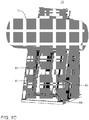
- FIGs. 1A - 1F illustrate various high level view of an imaging system 10 comprising: an imager 20, exhibiting a front end 22 and a back end 24; and an imager translation apparatus 30.
- FIG. 1A illustrates a high level side view of imaging system 10.
- FIG. 1B illustrates a high level front view of imaging system 10.
- FIG 1C illustrates a more detailed high level front view of imaging system 10.
- FIG 1D illustrates a high level rear view of imaging system 10.
- FIGs. 1A - ID will be described together.
- Imager 20 comprises a CT imager.
- Imager translation apparatus 30 comprises: an imager translation mechanism 40 comprising a motor 50 and a screw 60; a platform 70; a pair of rails 80; and a piston translation mechanism 90.
- Piston translation mechanism 90 comprises a pair of hydraulic pistons 95.
- Imager 20 is positioned on, and secured to, platform 70.
- Platform 70 is positioned over rails 80 and is arranged to slide thereover.
- Screw 60 is coupled to both motor 50 and platform 70 such that motor 50 is arranged to turn screw 60 and platform 70 is arranged to be translated along screw 60 in a worm drive configuration.
- hydraulic imager translation mechanism 90 further comprises a hydraulics liquid reservoir, a pressure sensor and an electric hydraulic pump, as will be described below.
- imager translation apparatus 30 is positioned on floor 160, a base 165 of imager translation apparatus 30 in contact with floor 160.
- Imager translation apparatus 30 extends generally upwards from base 165.
- imager translation apparatus 30 exhibits a generally right triangle shape with rails 80 extending along the hypotenuse thereof.
- motor 50 is arranged to turn screw 60.
- platform 70 is translated therealong.
- imager 20 is secured to platform 70, imager 20 is translated along a translation axis 150, responsive to the operation of motor 50 and screw 60.
- Translation axis 150 exhibits an acute imaging angle, denoted ⁇ , with the floor 160 of a room which contains therein imaging system 10.
- imaging angle ⁇ between translation axis 150 and floor 160 is between 55 - 85 degrees, such that the pelvis of a patient who is seated in an inclination of between 5 - 35 degrees can be imaged by imager 20.
- front end 22 of imager 20 is higher than back end 24 thereof.
- imaging angle ⁇ is between 65 - 75 degrees such that the pelvis of a patient seated in an inclination of between 15 - 25 degrees can imaged by imager 20. Additionally, when the patient is seated in an incline, preferably of about 20 degrees, the position is more comfortable than when seated in a vertical position and movement of the patient is less likely.
- imager 20 When screw 60 turns in a first direction, imager 20 is translated along translation axis 150 towards floor 160. When screw 60 turns in a second direction, opposing the first direction, imager 20 is translated along translation axis 150 away from floor 160.
- hydraulic pistons 95 act as a counterbalance for motor 50 and screw 60, as known to those skilled in the art at the time of the invention.
- the electric hydraulic pump (not shown) is arranged to adjust the liquid flow from the associated hydraulic reservoir so as to maintain a constant pressure at hydraulic pistons 95, responsive to the pressure sensor.
- a piston power mechanism (not shown) is arranged to provide motive power, specifically hydraulic power, to hydraulic pistons 95. Responsive to the provided hydraulic power, hydraulic pistons 95 are arranged to extend thereby pushing platform 70 along rails 80 away from floor 160. As a result, imager 20 is translated along translation axis 150 away from floor 160 and away from the patient which is being imaged. The patient can thus exit the chair and not get stuck by image 20.
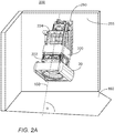
- FIGs. 2A - 2E illustrate various high level views of an imaging system 200, imaging system 200 comprising: an imager 20; an imager translation apparatus 210; and a piston power mechanism 215.
- FIG. 2A illustrates a first high level perspective view of imager 20 and imager translation apparatus 210.
- FIG. 2B illustrates a second high level perspective view of imager 20 and imager translation apparatus 210.
- FIG. 2C illustrates a high level side view of imager 20 and imager translation apparatus 210 in a retracted position.
- FIG. 2D illustrates a high level perspective side view of imager 20 and imager translation apparatus 210 in an extended position.
- FIG. 2E illustrates a high level perspective view of piston power mechanism 215.
- FIG. 2F illustrates a high level side view of piston power mechanism 215.
- FIGs. 2A - 2F are described together.
- Imager translation apparatus 210 comprises: a pair of rails 80; an extension unit 220; a screw 60; a motor (not shown); a counterweight 230; a piston translation mechanism comprising a piston 240; and a wall attachment unit 250.
- Imager 20 is positioned on, and secured to, a first end 222 of extension unit 220.
- Counterweight 230 is coupled to a second end 224 of extension unit 220 via a cable (not shown).
- a first end of piston 240 is positioned inside of counterweight 230 and second end of piston 240 is coupled to wall attachment unit 250.
- First end 222 of extension unit 220 opposes second end 224 of extension unit 220.
- Extension unit 220 is positioned on rails 80 and screw 60 extends through extension unit 220, extension unit 220 arranged to be translated along screw 60 responsive to the rotation thereof.
- Rails 80 are positioned on wall attachment unit 250 and wall attachment unit 250 is secured to a wall 255 of the room containing imaging system 200 with second end 224 of extension unit 220 facing wall 255.
- Piston power mechanism 215 comprises: a hydraulic liquid reservoir 260; a manual hydraulic pump 270; a movable pump handle 280; and a manual break release 290.
- manual break release 290 comprises a break release handle 300 and a cable (not shown).
- extension unit 220 is translated over rails 80 responsive to the motor turning screw 60. Responsive to the translation of extension unit 220 over rails 80, imager 20 is likewise translated along a translation axis 150.
- translation axis 150 exhibits an acute angle with floor 160, optionally an angle between 55 - 85 degrees, further optionally between 65 - 75 degrees.
- Extension unit 220 and imager 20 are counterbalanced by counterweight 230. Particularly, when imager 20 is translated along translation axis 150 towards a floor 160, counterweight 230 is pulled upwards along a counterweight axis 235, the mass of counterweight 230 providing counterbalance to imager 20.
- counterweight axis 235 exhibits a right angle with floor 160.
- piston 240 When electric power is provided to the motor rotating screw 60, piston 240 extends and retracts responsive to the movement of counterweight 230 along counterweight axis 235.
- piston power mechanism 215 is arranged to provide motive power to piston 240.
- piston 240 is a hydraulic piston and piston power mechanism 215 is arranged to provide hydraulic power to piston 240. This allows piston 240 to retract, thereby pulling counterweight 230 down counterweight axis 235. As a result, imager 20 is pulled along translation axis 150 away from floor 160, thereby avoiding trapping a patient within imager 20.
- movable pump handle 280 is inserted into manual hydraulic pump 270.
- a user holding movable pump handle 280 can then manually pump manual hydraulic pump 270.
- the pumping action of the user provides hydraulic energy to piston 240, via hydraulic liquid reservoir 260, to pull counterweight 230 down counterweight axis 235, as described above.
- hydraulic liquid reservoir 260 is not separately provided and manual hydraulic pump 270 is arranged to utilize the hydraulic liquid from a hydraulic liquid reservoir of piston 240 to provide hydraulic energy to piston 240 for translating counterweight 230 and imager 20.
- an emergency brake (not shown) is applied to extension unit 220 so it won't slide all the way down rails 80.
- the emergency brake Prior to operating manual hydraulic pump 270, the emergency brake is released via manual break release 290.
- a user pulls break release handle 300 from a first position to a second position.
- break release handle 300 pulls on the associated cable, which is also coupled to the emergency break.
- the tension of the cable increases thereby pulling on the emergency break and allowing extension unit 220 to be translated along rails 80.
- break release handle 300 is then secured to the second position.
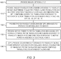
- FIG. 3 illustrates a high level flow chart of an imager translation method.
- an imager is provided, optionally a CT imager.
- an imager translation mechanism is provided. Responsive to a provided electric power, the imager translation mechanism arranged to translate the imager of stage 1000 along a predetermined translation axis in each of a first direction and a second direction responsive to a provided electrical power, the second direction opposing the first direction.
- the predetermined translation axis exhibits an imaging angle with a floor, the first direction being toward the floor along the translation axis. Additionally, the imaging angle is an acute angle of less than 90 degrees and greater than 0 degrees, optionally between 55 - 85 degrees, further optionally between 65 - 75 degrees.
- the imager translation mechanism comprises a screw, the translation of the imager along the translation axis responsive to a rotation of the screw by an electrically driven motor. Particularly, responsive to rotation of the screw in a first rotational direction, the imager is translated along the translation axis in the first direction. Responsive to rotation of the screw in a second rotation direction, the imager is translated along the translation axis in the second direction.
- a piston translation mechanism is provided.
- the piston translation mechanism comprises one or more hydraulic pistons.
- the piston translation mechanism is arranged to provide counterbalance to the imager of stage 1000.
- stage 1030 motive power is provided to the piston translation mechanism of stage 1020, the motive power optionally being hydraulic power.
- the piston translation is arranged to translate the imager of stage 1000 in the second direction responsive to the provided motive power in the absence of the provided electrical power.
- a counterweight is provided, the counterweight arranged to translate along a counterweight axis, the provided counterweight arranged to provide counterbalance to the provided imager.
- the arrangement of stage 1030, of the provided piston translation mechanism to translate the provided imager in the second direction, comprises translating the provided counterweight along the counterweight axis.
Landscapes
- Health & Medical Sciences (AREA)
- Life Sciences & Earth Sciences (AREA)
- Engineering & Computer Science (AREA)
- Medical Informatics (AREA)
- Biomedical Technology (AREA)
- Veterinary Medicine (AREA)
- Radiology & Medical Imaging (AREA)
- Animal Behavior & Ethology (AREA)
- General Health & Medical Sciences (AREA)
- Public Health (AREA)
- Nuclear Medicine, Radiotherapy & Molecular Imaging (AREA)
- Pathology (AREA)
- Biophysics (AREA)
- Physics & Mathematics (AREA)
- High Energy & Nuclear Physics (AREA)
- Optics & Photonics (AREA)
- Heart & Thoracic Surgery (AREA)
- Molecular Biology (AREA)
- Surgery (AREA)
- Theoretical Computer Science (AREA)
- Pulmonology (AREA)
- Apparatus For Radiation Diagnosis (AREA)
Claims (10)
- Abbildungssystem (200), Folgendes umfassend:einen Computertomographie-(CT)-Bildgeber (20);einen Bildgeberverlagerungsmechanismus (210), der angeordnet ist, um den CT-Bildgeber (20) entlang einer vorbestimmten Verlagerungsachse (150) in jeweils einer ersten Richtung und einer zweiten Richtung als Reaktion auf eine bereitgestellte elektrische Leistung zu verschieben, wobei die vorbestimmte Verlagerungsachse (150) einen Abbildungswinkel (a) mit dem Boden (160) eines Raums aufweist, der das Abbildungssystem (200) enthält, wobei der Abbildungswinkel zwischen der Verlagerungsachse (150) und dem Boden (160) kleiner als 90 Grad und größer als 0 Grad ist, wobei eine erste Richtung entlang der Verlagerungsachse (150) in Richtung des Bodens (160) ist, wobei die zweite Richtung der ersten Richtung entgegengesetzt ist;dadurch gekennzeichnet, dass das Abbildungssystem ferner Folgendes umfasst:einen Kolbenverlagerungsmechanismus (240);ein Gegengewicht (230), das angeordnet ist, um sich entlang einer Gegengewichtsachse (235) zu verlagern, wobei das Gegengewicht (230) angeordnet ist, um dem CT-Bildgeber (20) ein Gegengewicht bereitzustellen; undeinen Kolbenantriebsmechanismus (215), der angeordnet ist, um dem Kolbenverlagerungsmechanismus (240) Antriebskraft bereitzustellen,wobei der Kolbenverlagerungsmechanismus (240) angeordnet ist, um den CT-Bildgeber (20) als Reaktion auf die bereitgestellte Bewegungsleistung in Abwesenheit der bereitgestellten elektrischen Leistung in der zweiten Richtung zu verschieben, undwobei die Anordnung des Kolbenverlagerungsmechanismus (240) zum Verschieben des CT-Bildgebers (20) in die zweite Richtung das Verschieben des Gegengewichts (230) entlang der Gegengewichtsachse (235) umfasst und folglich der CT-Bildgeber (20) in die zweite Richtung verschoben wird.
- System nach Anspruch 1, wobei der Bildgeberverlagerungsmechanismus (210) Folgendes umfasst:eine Schraube (60); undeinen Motor (50), wobei der Motor (50) angeordnet ist, um die Schraube (60) zu drehen, wobei die Verlagerung des CT-Bildgebers (20) entlang der Verlagerungsachse (150) auf die Drehung der Schraube (60) anspricht,wobei die bereitgestellte Antriebskraft hydraulische Kraft umfasst.
- System nach Anspruch 1, wobei ein Ende des Kolbenverlagerungsmechanismus (240) innerhalb des Gegengewichts (230) positioniert ist.
- System nach Anspruch 1, wobei der Abbildungswinkel (a) 55-85 Grad beträgt.
- System nach Anspruch 4, wobei der Abbildungswinkel (a) 65-75 Grad beträgt.
- Bildgebungsverfahren, wobei das Verfahren Folgendes umfasst:Bereitstellen (1000) eines Computertomographie-(CT)-Bildgebers (20);Bereitstellen (1010) eines Bildgeberverlagerungsmechanismus (210), der angeordnet ist, um den CT-Bildgeber (20) entlang einer vorbestimmten Verlagerungsachse (150) in jeweils einer ersten Richtung und einer zweiten Richtung als Reaktion auf eine bereitgestellte elektrische Leistung zu verschieben, wobei die vorbestimmte Verlagerungsachse (150) einen Abbildungswinkel (a) mit einem Boden (160) aufweist, wobei der Abbildungswinkel (a) kleiner als 90 Grad und größer als 0 Grad ist, wobei eine erste Richtung entlang der Verlagerungsachse (150) in Richtung des Bodens (160) ist, wobei die zweite Richtung der ersten Richtung entgegengesetzt ist, dadurch gekennzeichnet, dass das Verfahren ferner Folgendes umfasst:Bereitstellen (1020) eines Kolbenverlagerungsmechanismus (240);Bereitstellen (1030) einer Antriebskraft für den bereitgestellten Kolbenverlagerungsmechanismus (90);Bereitstellen (1040) eines Gegengewichts (230), das angeordnet ist, um sich entlang einer Gegengewichtsachse (235) zu verlagern, wobei das bereitgestellte Gegengewicht (230) angeordnet ist, um dem bereitgestellten CT-Bildgeber (20) ein Gegengewicht bereitzustellen;wobei der bereitgestellte Kolbenverlagerungsmechanismus (240) angeordnet ist, um den CT-Bildgeber (20) als Reaktion auf die bereitgestellte Bewegungsleistung in Abwesenheit der bereitgestellten elektrischen Leistung in der zweiten Richtung zu verschieben, undwobei die Anordnung des bereitgestellten Kolbenverlagerungsmechanismus (240) zum Verschieben des bereitgestellten CT-Bildgebers (20) in die zweite Richtung das Verschieben des bereitgestellten Gegengewichts (230) entlang der Gegengewichtsachse (235) umfasst und folglich der CT-Bildgeber (20) in die zweite Richtung verschoben wird.
- Verfahren nach Anspruch 6, wobei der bereitgestellte Bildgeberverlagerungsmechanismus (210) eine Schraube (60) umfasst,
wobei das Verfahren ferner das Drehen (1010) der Schraube (60) umfasst, wobei das Verlagern des bereitgestellten CT-Bildgebers (20) entlang der Verlagerungsachse (150) auf die Drehung der Schraube (60) anspricht, und
wobei die bereitgestellte Antriebskraft hydraulische Kraft umfasst. - Verfahren nach Anspruch 6, wobei ein Ende des bereitgestellten Kolbenverlagerungsmechanismus (240) innerhalb des Gegengewichts (230) positioniert ist.
- Verfahren nach Anspruch 6, wobei der Abbildungswinkel (a) 55-85 Grad beträgt.
- Verfahren nach Anspruch 9, wobei der Abbildungswinkel (a) 65-75 Grad beträgt.
Applications Claiming Priority (2)
| Application Number | Priority Date | Filing Date | Title |
|---|---|---|---|
| US201562200038P | 2015-08-02 | 2015-08-02 | |
| PCT/IL2016/050844 WO2017021962A1 (en) | 2015-08-02 | 2016-08-02 | Imaging system and method |
Publications (2)
| Publication Number | Publication Date |
|---|---|
| EP3328282A1 EP3328282A1 (de) | 2018-06-06 |
| EP3328282B1 true EP3328282B1 (de) | 2020-04-08 |
Family
ID=56896747
Family Applications (1)
| Application Number | Title | Priority Date | Filing Date |
|---|---|---|---|
| EP16763593.7A Active EP3328282B1 (de) | 2015-08-02 | 2016-08-02 | Bildgebungssystem und -verfahren |
Country Status (4)
| Country | Link |
|---|---|
| US (1) | US11076816B2 (de) |
| EP (1) | EP3328282B1 (de) |
| CN (1) | CN108135561A (de) |
| WO (1) | WO2017021962A1 (de) |
Families Citing this family (4)
| Publication number | Priority date | Publication date | Assignee | Title |
|---|---|---|---|---|
| WO2017013662A2 (en) * | 2015-07-22 | 2017-01-26 | P-Cure, Ltd. | Irradiation treatment plan system and method |
| GB2576337A (en) * | 2018-08-15 | 2020-02-19 | Elekta ltd | Adjustable support |
| ES2966150T3 (es) * | 2018-10-18 | 2024-04-18 | medPhoton GmbH | Sistema de anillo móvil de formación de imágenes |
| US11229409B2 (en) | 2018-10-18 | 2022-01-25 | medPhoton GmbH | Mobile imaging ring system |
Family Cites Families (15)
| Publication number | Priority date | Publication date | Assignee | Title |
|---|---|---|---|---|
| DE4240791A1 (de) * | 1992-12-04 | 1994-06-09 | Philips Patentverwaltung | Röntgengerät mit einem Hydrauliksystem |
| US7224764B2 (en) * | 2003-08-07 | 2007-05-29 | Xoran Technologies, Inc. | Stand-up CT scanner |
| US7847275B2 (en) | 2007-05-24 | 2010-12-07 | Pcure Ltd. | Method and apparatus for teletherapy positioning and validation |
| US8009794B2 (en) | 2008-01-30 | 2011-08-30 | Varian Medical Systems, Inc. | Methods, apparatus, and computer-program products for increasing accuracy in cone-beam computed tomography |
| CN201227280Y (zh) * | 2008-07-30 | 2009-04-29 | 高文祥 | 全自动c型臂x光机c型臂双轴向旋转结构 |
| CN201328818Y (zh) * | 2008-12-29 | 2009-10-21 | 南京普爱射线影像设备有限公司 | 一种c臂在轨道内既可电动也可手动的医用x线机 |
| CN201642057U (zh) * | 2009-12-29 | 2010-11-24 | 上海西门子医疗器械有限公司 | 可移动式检查床 |
| EP2664360B1 (de) | 2010-02-24 | 2015-09-09 | Accuray Incorporated | Bildgeführtes Gantry-Strahlentherapiesystem und zugehörige Trackingverfahren |
| US9833208B2 (en) * | 2010-03-12 | 2017-12-05 | Shimadzu Corporation | Body section imaging apparatus |
| CN202821390U (zh) * | 2012-09-26 | 2013-03-27 | 珠海普利德医疗设备有限公司 | 射线机线架安装总成 |
| WO2014049597A1 (en) | 2012-09-28 | 2014-04-03 | P-Cure Ltd. | Apparatus and method for providing patient imaging |
| EP2903522B1 (de) * | 2012-10-08 | 2016-09-21 | Carestream Health, Inc. | Extremitätenbildgebungsvorrichtung für digitale volumentomografie |
| CN203539367U (zh) * | 2013-11-27 | 2014-04-16 | 黎剑锋 | 一种体检车电动体检装置 |
| EP3087424A4 (de) | 2013-12-23 | 2017-09-27 | Camplex, Inc. | Chirurgische visualisierungssysteme |
| CN203977932U (zh) * | 2014-07-28 | 2014-12-03 | 杨振华 | 立体停车装置 |
-
2016
- 2016-08-02 EP EP16763593.7A patent/EP3328282B1/de active Active
- 2016-08-02 CN CN201680057553.8A patent/CN108135561A/zh active Pending
- 2016-08-02 US US15/748,187 patent/US11076816B2/en active Active
- 2016-08-02 WO PCT/IL2016/050844 patent/WO2017021962A1/en not_active Ceased
Non-Patent Citations (1)
| Title |
|---|
| None * |
Also Published As
| Publication number | Publication date |
|---|---|
| CN108135561A (zh) | 2018-06-08 |
| US20180220975A1 (en) | 2018-08-09 |
| EP3328282A1 (de) | 2018-06-06 |
| WO2017021962A1 (en) | 2017-02-09 |
| US11076816B2 (en) | 2021-08-03 |
Similar Documents
| Publication | Publication Date | Title |
|---|---|---|
| US7453076B2 (en) | Bi-polar treatment facility for treating target cells with both positive and negative ions | |
| US9072894B2 (en) | Method and apparatus for radioablation of regular targets such as sympathetic nerves | |
| EP3328282B1 (de) | Bildgebungssystem und -verfahren | |
| US8613694B2 (en) | Method for biological modulation of radiation therapy | |
| US20040162457A1 (en) | Antiproton production and delivery for imaging and termination of undersirable cells | |
| US11259760B2 (en) | Apparatus and method for providing patient imaging | |
| US20220071591A1 (en) | Ultrasound positioning device, system, and method | |
| US10188878B2 (en) | Small beam area, mid-voltage radiotherapy system with reduced skin dose, reduced scatter around the treatment volume, and improved overall accuracy | |
| US20160310763A1 (en) | Small beam area, mid-voltage radiotherapy system with reduced skin dose, reduced scatter around the treatment volume, and improved overall accuracy | |
| RU2753639C1 (ru) | Аппарат для корпускулярной лучевой терапии | |
| CN204219617U (zh) | 六自由度并联放射治疗床 | |
| WO2019077135A1 (en) | RADIOTHERAPY SYSTEM | |
| EP2704797B1 (de) | Anordnung eines universellen teletherapeutischen behandlungsraums | |
| EP3517173A1 (de) | Ultraschallpositionierungsvorrichtung, system und verfahren | |
| CN102430208B (zh) | 一种自动缩野的肿瘤放射治疗装置 | |
| JP6433792B2 (ja) | 粒子線治療装置及びこれを用いた撮像方法 | |
| WO2004075975A2 (en) | Mobile radiation treatment vehicle and method | |
| EP4696374A1 (de) | Strahlentherapiesystem für vorhofflimmern | |
| US10124191B2 (en) | Hadron therapy installation comprising an imaging device | |
| CN202427061U (zh) | 一种自动缩野的肿瘤放射治疗装置 | |
| CN105477793A (zh) | 一种核放射治疗源容器结构 | |
| Yun et al. | Needle guide device development for CT system-based biopsy |
Legal Events
| Date | Code | Title | Description |
|---|---|---|---|
| STAA | Information on the status of an ep patent application or granted ep patent |
Free format text: STATUS: THE INTERNATIONAL PUBLICATION HAS BEEN MADE |
|
| PUAI | Public reference made under article 153(3) epc to a published international application that has entered the european phase |
Free format text: ORIGINAL CODE: 0009012 |
|
| STAA | Information on the status of an ep patent application or granted ep patent |
Free format text: STATUS: REQUEST FOR EXAMINATION WAS MADE |
|
| 17P | Request for examination filed |
Effective date: 20180301 |
|
| AK | Designated contracting states |
Kind code of ref document: A1 Designated state(s): AL AT BE BG CH CY CZ DE DK EE ES FI FR GB GR HR HU IE IS IT LI LT LU LV MC MK MT NL NO PL PT RO RS SE SI SK SM TR |
|
| AX | Request for extension of the european patent |
Extension state: BA ME |
|
| DAV | Request for validation of the european patent (deleted) | ||
| DAX | Request for extension of the european patent (deleted) | ||
| GRAP | Despatch of communication of intention to grant a patent |
Free format text: ORIGINAL CODE: EPIDOSNIGR1 |
|
| STAA | Information on the status of an ep patent application or granted ep patent |
Free format text: STATUS: GRANT OF PATENT IS INTENDED |
|
| INTG | Intention to grant announced |
Effective date: 20191112 |
|
| RAP1 | Party data changed (applicant data changed or rights of an application transferred) |
Owner name: P-CURE LTD. |
|
| GRAS | Grant fee paid |
Free format text: ORIGINAL CODE: EPIDOSNIGR3 |
|
| GRAA | (expected) grant |
Free format text: ORIGINAL CODE: 0009210 |
|
| STAA | Information on the status of an ep patent application or granted ep patent |
Free format text: STATUS: THE PATENT HAS BEEN GRANTED |
|
| AK | Designated contracting states |
Kind code of ref document: B1 Designated state(s): AL AT BE BG CH CY CZ DE DK EE ES FI FR GB GR HR HU IE IS IT LI LT LU LV MC MK MT NL NO PL PT RO RS SE SI SK SM TR |
|
| REG | Reference to a national code |
Ref country code: CH Ref legal event code: EP Ref country code: AT Ref legal event code: REF Ref document number: 1253260 Country of ref document: AT Kind code of ref document: T Effective date: 20200415 |
|
| REG | Reference to a national code |
Ref country code: DE Ref legal event code: R096 Ref document number: 602016033652 Country of ref document: DE |
|
| REG | Reference to a national code |
Ref country code: IE Ref legal event code: FG4D |
|
| REG | Reference to a national code |
Ref country code: NL Ref legal event code: MP Effective date: 20200408 |
|
| REG | Reference to a national code |
Ref country code: LT Ref legal event code: MG4D |
|
| PG25 | Lapsed in a contracting state [announced via postgrant information from national office to epo] |
Ref country code: LT Free format text: LAPSE BECAUSE OF FAILURE TO SUBMIT A TRANSLATION OF THE DESCRIPTION OR TO PAY THE FEE WITHIN THE PRESCRIBED TIME-LIMIT Effective date: 20200408 Ref country code: GR Free format text: LAPSE BECAUSE OF FAILURE TO SUBMIT A TRANSLATION OF THE DESCRIPTION OR TO PAY THE FEE WITHIN THE PRESCRIBED TIME-LIMIT Effective date: 20200709 Ref country code: PT Free format text: LAPSE BECAUSE OF FAILURE TO SUBMIT A TRANSLATION OF THE DESCRIPTION OR TO PAY THE FEE WITHIN THE PRESCRIBED TIME-LIMIT Effective date: 20200817 Ref country code: NL Free format text: LAPSE BECAUSE OF FAILURE TO SUBMIT A TRANSLATION OF THE DESCRIPTION OR TO PAY THE FEE WITHIN THE PRESCRIBED TIME-LIMIT Effective date: 20200408 Ref country code: SE Free format text: LAPSE BECAUSE OF FAILURE TO SUBMIT A TRANSLATION OF THE DESCRIPTION OR TO PAY THE FEE WITHIN THE PRESCRIBED TIME-LIMIT Effective date: 20200408 Ref country code: NO Free format text: LAPSE BECAUSE OF FAILURE TO SUBMIT A TRANSLATION OF THE DESCRIPTION OR TO PAY THE FEE WITHIN THE PRESCRIBED TIME-LIMIT Effective date: 20200708 Ref country code: IS Free format text: LAPSE BECAUSE OF FAILURE TO SUBMIT A TRANSLATION OF THE DESCRIPTION OR TO PAY THE FEE WITHIN THE PRESCRIBED TIME-LIMIT Effective date: 20200808 Ref country code: FI Free format text: LAPSE BECAUSE OF FAILURE TO SUBMIT A TRANSLATION OF THE DESCRIPTION OR TO PAY THE FEE WITHIN THE PRESCRIBED TIME-LIMIT Effective date: 20200408 |
|
| REG | Reference to a national code |
Ref country code: AT Ref legal event code: MK05 Ref document number: 1253260 Country of ref document: AT Kind code of ref document: T Effective date: 20200408 |
|
| PG25 | Lapsed in a contracting state [announced via postgrant information from national office to epo] |
Ref country code: RS Free format text: LAPSE BECAUSE OF FAILURE TO SUBMIT A TRANSLATION OF THE DESCRIPTION OR TO PAY THE FEE WITHIN THE PRESCRIBED TIME-LIMIT Effective date: 20200408 Ref country code: HR Free format text: LAPSE BECAUSE OF FAILURE TO SUBMIT A TRANSLATION OF THE DESCRIPTION OR TO PAY THE FEE WITHIN THE PRESCRIBED TIME-LIMIT Effective date: 20200408 Ref country code: BG Free format text: LAPSE BECAUSE OF FAILURE TO SUBMIT A TRANSLATION OF THE DESCRIPTION OR TO PAY THE FEE WITHIN THE PRESCRIBED TIME-LIMIT Effective date: 20200708 Ref country code: LV Free format text: LAPSE BECAUSE OF FAILURE TO SUBMIT A TRANSLATION OF THE DESCRIPTION OR TO PAY THE FEE WITHIN THE PRESCRIBED TIME-LIMIT Effective date: 20200408 |
|
| PG25 | Lapsed in a contracting state [announced via postgrant information from national office to epo] |
Ref country code: AL Free format text: LAPSE BECAUSE OF FAILURE TO SUBMIT A TRANSLATION OF THE DESCRIPTION OR TO PAY THE FEE WITHIN THE PRESCRIBED TIME-LIMIT Effective date: 20200408 |
|
| REG | Reference to a national code |
Ref country code: DE Ref legal event code: R097 Ref document number: 602016033652 Country of ref document: DE |
|
| PG25 | Lapsed in a contracting state [announced via postgrant information from national office to epo] |
Ref country code: RO Free format text: LAPSE BECAUSE OF FAILURE TO SUBMIT A TRANSLATION OF THE DESCRIPTION OR TO PAY THE FEE WITHIN THE PRESCRIBED TIME-LIMIT Effective date: 20200408 Ref country code: CZ Free format text: LAPSE BECAUSE OF FAILURE TO SUBMIT A TRANSLATION OF THE DESCRIPTION OR TO PAY THE FEE WITHIN THE PRESCRIBED TIME-LIMIT Effective date: 20200408 Ref country code: ES Free format text: LAPSE BECAUSE OF FAILURE TO SUBMIT A TRANSLATION OF THE DESCRIPTION OR TO PAY THE FEE WITHIN THE PRESCRIBED TIME-LIMIT Effective date: 20200408 Ref country code: EE Free format text: LAPSE BECAUSE OF FAILURE TO SUBMIT A TRANSLATION OF THE DESCRIPTION OR TO PAY THE FEE WITHIN THE PRESCRIBED TIME-LIMIT Effective date: 20200408 Ref country code: SM Free format text: LAPSE BECAUSE OF FAILURE TO SUBMIT A TRANSLATION OF THE DESCRIPTION OR TO PAY THE FEE WITHIN THE PRESCRIBED TIME-LIMIT Effective date: 20200408 Ref country code: AT Free format text: LAPSE BECAUSE OF FAILURE TO SUBMIT A TRANSLATION OF THE DESCRIPTION OR TO PAY THE FEE WITHIN THE PRESCRIBED TIME-LIMIT Effective date: 20200408 Ref country code: IT Free format text: LAPSE BECAUSE OF FAILURE TO SUBMIT A TRANSLATION OF THE DESCRIPTION OR TO PAY THE FEE WITHIN THE PRESCRIBED TIME-LIMIT Effective date: 20200408 Ref country code: DK Free format text: LAPSE BECAUSE OF FAILURE TO SUBMIT A TRANSLATION OF THE DESCRIPTION OR TO PAY THE FEE WITHIN THE PRESCRIBED TIME-LIMIT Effective date: 20200408 |
|
| PLBE | No opposition filed within time limit |
Free format text: ORIGINAL CODE: 0009261 |
|
| STAA | Information on the status of an ep patent application or granted ep patent |
Free format text: STATUS: NO OPPOSITION FILED WITHIN TIME LIMIT |
|
| PG25 | Lapsed in a contracting state [announced via postgrant information from national office to epo] |
Ref country code: SK Free format text: LAPSE BECAUSE OF FAILURE TO SUBMIT A TRANSLATION OF THE DESCRIPTION OR TO PAY THE FEE WITHIN THE PRESCRIBED TIME-LIMIT Effective date: 20200408 Ref country code: PL Free format text: LAPSE BECAUSE OF FAILURE TO SUBMIT A TRANSLATION OF THE DESCRIPTION OR TO PAY THE FEE WITHIN THE PRESCRIBED TIME-LIMIT Effective date: 20200408 |
|
| 26N | No opposition filed |
Effective date: 20210112 |
|
| PG25 | Lapsed in a contracting state [announced via postgrant information from national office to epo] |
Ref country code: MC Free format text: LAPSE BECAUSE OF FAILURE TO SUBMIT A TRANSLATION OF THE DESCRIPTION OR TO PAY THE FEE WITHIN THE PRESCRIBED TIME-LIMIT Effective date: 20200408 |
|
| REG | Reference to a national code |
Ref country code: CH Ref legal event code: PL |
|
| PG25 | Lapsed in a contracting state [announced via postgrant information from national office to epo] |
Ref country code: LU Free format text: LAPSE BECAUSE OF NON-PAYMENT OF DUE FEES Effective date: 20200802 Ref country code: LI Free format text: LAPSE BECAUSE OF NON-PAYMENT OF DUE FEES Effective date: 20200831 Ref country code: CH Free format text: LAPSE BECAUSE OF NON-PAYMENT OF DUE FEES Effective date: 20200831 |
|
| REG | Reference to a national code |
Ref country code: BE Ref legal event code: MM Effective date: 20200831 |
|
| PG25 | Lapsed in a contracting state [announced via postgrant information from national office to epo] |
Ref country code: SI Free format text: LAPSE BECAUSE OF FAILURE TO SUBMIT A TRANSLATION OF THE DESCRIPTION OR TO PAY THE FEE WITHIN THE PRESCRIBED TIME-LIMIT Effective date: 20200408 |
|
| PG25 | Lapsed in a contracting state [announced via postgrant information from national office to epo] |
Ref country code: BE Free format text: LAPSE BECAUSE OF NON-PAYMENT OF DUE FEES Effective date: 20200831 Ref country code: IE Free format text: LAPSE BECAUSE OF NON-PAYMENT OF DUE FEES Effective date: 20200802 |
|
| PG25 | Lapsed in a contracting state [announced via postgrant information from national office to epo] |
Ref country code: TR Free format text: LAPSE BECAUSE OF FAILURE TO SUBMIT A TRANSLATION OF THE DESCRIPTION OR TO PAY THE FEE WITHIN THE PRESCRIBED TIME-LIMIT Effective date: 20200408 Ref country code: MT Free format text: LAPSE BECAUSE OF FAILURE TO SUBMIT A TRANSLATION OF THE DESCRIPTION OR TO PAY THE FEE WITHIN THE PRESCRIBED TIME-LIMIT Effective date: 20200408 Ref country code: CY Free format text: LAPSE BECAUSE OF FAILURE TO SUBMIT A TRANSLATION OF THE DESCRIPTION OR TO PAY THE FEE WITHIN THE PRESCRIBED TIME-LIMIT Effective date: 20200408 |
|
| PG25 | Lapsed in a contracting state [announced via postgrant information from national office to epo] |
Ref country code: MK Free format text: LAPSE BECAUSE OF FAILURE TO SUBMIT A TRANSLATION OF THE DESCRIPTION OR TO PAY THE FEE WITHIN THE PRESCRIBED TIME-LIMIT Effective date: 20200408 |
|
| P01 | Opt-out of the competence of the unified patent court (upc) registered |
Effective date: 20230608 |
|
| PGFP | Annual fee paid to national office [announced via postgrant information from national office to epo] |
Ref country code: DE Payment date: 20250820 Year of fee payment: 10 |
|
| PGFP | Annual fee paid to national office [announced via postgrant information from national office to epo] |
Ref country code: GB Payment date: 20250821 Year of fee payment: 10 |
|
| PGFP | Annual fee paid to national office [announced via postgrant information from national office to epo] |
Ref country code: FR Payment date: 20250828 Year of fee payment: 10 |