EP3328271B1 - Verfahren zur nichtinvasiven bestimmung von vitalparametern eines lebenden organismus - Google Patents
Verfahren zur nichtinvasiven bestimmung von vitalparametern eines lebenden organismus Download PDFInfo
- Publication number
- EP3328271B1 EP3328271B1 EP16757829.3A EP16757829A EP3328271B1 EP 3328271 B1 EP3328271 B1 EP 3328271B1 EP 16757829 A EP16757829 A EP 16757829A EP 3328271 B1 EP3328271 B1 EP 3328271B1
- Authority
- EP
- European Patent Office
- Prior art keywords
- pulse wave
- brightness
- measurement
- pulse
- colours
- Prior art date
- Legal status (The legal status is an assumption and is not a legal conclusion. Google has not performed a legal analysis and makes no representation as to the accuracy of the status listed.)
- Active
Links
- 238000000034 method Methods 0.000 title claims description 32
- 230000033001 locomotion Effects 0.000 claims description 45
- 238000005259 measurement Methods 0.000 claims description 41
- 239000003086 colorant Substances 0.000 claims description 36
- 230000036772 blood pressure Effects 0.000 claims description 29
- 230000008859 change Effects 0.000 claims description 18
- 230000001133 acceleration Effects 0.000 claims description 10
- 230000003287 optical effect Effects 0.000 claims description 6
- 238000012544 monitoring process Methods 0.000 claims description 5
- 206010021703 Indifference Diseases 0.000 claims description 4
- 210000000748 cardiovascular system Anatomy 0.000 claims description 4
- 230000002706 hydrostatic effect Effects 0.000 claims description 4
- 238000001514 detection method Methods 0.000 claims description 3
- 230000006978 adaptation Effects 0.000 claims 1
- 238000009529 body temperature measurement Methods 0.000 claims 1
- 238000002847 impedance measurement Methods 0.000 claims 1
- 230000003595 spectral effect Effects 0.000 claims 1
- 239000008280 blood Substances 0.000 description 10
- 210000004369 blood Anatomy 0.000 description 10
- 210000001519 tissue Anatomy 0.000 description 10
- 230000002792 vascular Effects 0.000 description 10
- 230000029058 respiratory gaseous exchange Effects 0.000 description 9
- 238000009530 blood pressure measurement Methods 0.000 description 7
- 238000011156 evaluation Methods 0.000 description 5
- 239000000203 mixture Substances 0.000 description 5
- 230000035515 penetration Effects 0.000 description 5
- QVGXLLKOCUKJST-UHFFFAOYSA-N atomic oxygen Chemical compound [O] QVGXLLKOCUKJST-UHFFFAOYSA-N 0.000 description 4
- 230000006870 function Effects 0.000 description 4
- 239000001301 oxygen Substances 0.000 description 4
- 229910052760 oxygen Inorganic materials 0.000 description 4
- 238000012545 processing Methods 0.000 description 4
- 230000000241 respiratory effect Effects 0.000 description 4
- 239000000126 substance Substances 0.000 description 4
- 206010020772 Hypertension Diseases 0.000 description 3
- 230000008901 benefit Effects 0.000 description 3
- 230000007423 decrease Effects 0.000 description 3
- 239000007789 gas Substances 0.000 description 3
- 230000002093 peripheral effect Effects 0.000 description 3
- 238000007639 printing Methods 0.000 description 3
- 208000004301 Sinus Arrhythmia Diseases 0.000 description 2
- 238000006243 chemical reaction Methods 0.000 description 2
- 229940079593 drug Drugs 0.000 description 2
- 239000003814 drug Substances 0.000 description 2
- 230000000694 effects Effects 0.000 description 2
- 230000002349 favourable effect Effects 0.000 description 2
- 238000001914 filtration Methods 0.000 description 2
- 230000001771 impaired effect Effects 0.000 description 2
- 239000000463 material Substances 0.000 description 2
- 239000011159 matrix material Substances 0.000 description 2
- 238000003825 pressing Methods 0.000 description 2
- 230000008569 process Effects 0.000 description 2
- 238000007665 sagging Methods 0.000 description 2
- 238000012546 transfer Methods 0.000 description 2
- 206010003210 Arteriosclerosis Diseases 0.000 description 1
- 206010005746 Blood pressure fluctuation Diseases 0.000 description 1
- 208000010201 Exanthema Diseases 0.000 description 1
- 241000282412 Homo Species 0.000 description 1
- 230000003187 abdominal effect Effects 0.000 description 1
- 230000002159 abnormal effect Effects 0.000 description 1
- 230000009102 absorption Effects 0.000 description 1
- 238000010521 absorption reaction Methods 0.000 description 1
- 210000000577 adipose tissue Anatomy 0.000 description 1
- 238000004458 analytical method Methods 0.000 description 1
- 210000002376 aorta thoracic Anatomy 0.000 description 1
- 210000001765 aortic valve Anatomy 0.000 description 1
- 208000011775 arteriosclerosis disease Diseases 0.000 description 1
- 230000006399 behavior Effects 0.000 description 1
- 230000005540 biological transmission Effects 0.000 description 1
- 230000015572 biosynthetic process Effects 0.000 description 1
- 230000035565 breathing frequency Effects 0.000 description 1
- 238000004364 calculation method Methods 0.000 description 1
- 239000000969 carrier Substances 0.000 description 1
- 210000003169 central nervous system Anatomy 0.000 description 1
- 238000004891 communication Methods 0.000 description 1
- 230000007812 deficiency Effects 0.000 description 1
- 201000010099 disease Diseases 0.000 description 1
- 208000037265 diseases, disorders, signs and symptoms Diseases 0.000 description 1
- 230000002526 effect on cardiovascular system Effects 0.000 description 1
- 230000005670 electromagnetic radiation Effects 0.000 description 1
- 238000005516 engineering process Methods 0.000 description 1
- 201000005884 exanthem Diseases 0.000 description 1
- 239000012530 fluid Substances 0.000 description 1
- 239000011521 glass Substances 0.000 description 1
- 238000009532 heart rate measurement Methods 0.000 description 1
- 238000003384 imaging method Methods 0.000 description 1
- 230000006872 improvement Effects 0.000 description 1
- 230000007774 longterm Effects 0.000 description 1
- 235000015263 low fat diet Nutrition 0.000 description 1
- 235000014659 low sodium diet Nutrition 0.000 description 1
- 239000003550 marker Substances 0.000 description 1
- 238000000691 measurement method Methods 0.000 description 1
- 230000037081 physical activity Effects 0.000 description 1
- 230000002250 progressing effect Effects 0.000 description 1
- 230000005855 radiation Effects 0.000 description 1
- 206010037844 rash Diseases 0.000 description 1
- 230000036632 reaction speed Effects 0.000 description 1
- 238000001454 recorded image Methods 0.000 description 1
- 230000009467 reduction Effects 0.000 description 1
- 230000000630 rising effect Effects 0.000 description 1
- 208000024891 symptom Diseases 0.000 description 1
- 239000006163 transport media Substances 0.000 description 1
- 230000001960 triggered effect Effects 0.000 description 1
- 230000001457 vasomotor Effects 0.000 description 1
Images


Classifications
-
- A—HUMAN NECESSITIES
- A61—MEDICAL OR VETERINARY SCIENCE; HYGIENE
- A61B—DIAGNOSIS; SURGERY; IDENTIFICATION
- A61B5/00—Measuring for diagnostic purposes; Identification of persons
- A61B5/02—Detecting, measuring or recording pulse, heart rate, blood pressure or blood flow; Combined pulse/heart-rate/blood pressure determination; Evaluating a cardiovascular condition not otherwise provided for, e.g. using combinations of techniques provided for in this group with electrocardiography or electroauscultation; Heart catheters for measuring blood pressure
- A61B5/024—Detecting, measuring or recording pulse rate or heart rate
- A61B5/02416—Detecting, measuring or recording pulse rate or heart rate using photoplethysmograph signals, e.g. generated by infrared radiation
- A61B5/02427—Details of sensor
- A61B5/02433—Details of sensor for infrared radiation
Definitions
- the invention relates to a method for the non-invasive determination of vital parameters, in particular for the one-time or continuous measurement and/or monitoring of the blood pressure of a living organism using a device, in particular a smart device, with at least one optical recording unit and a computing unit by recording a sequence of individual image data a limited area of the skin of the living organism using the optical recording unit, evaluation of the image data, including determination of a pulse wave propagation time and detection of the brightness of the pulse wave and determination of one or more vital parameters of the organism from the image data using the computing unit.
- the WO 2015 / 098977 A1 relates to pulse wave monitors having a pulse waveform information acquisition unit that optically acquires pulse waveform information from a portion of a living body, and a pulse wave feature amount calculation unit that calculates a pulse wave feature amount based on the pulse waveform information.
- a video imaging system is used to acquire a time-varying source signal from a proximal and distal region of a patient.
- the images are processed to view localized areas of a proximal and distal region of the patient's skin.
- a time series signal for each of the proximal and distal regions is extracted from the source video images, and a phase of each of the extracted signals is calculated for each region.
- a phase difference is calculated between the time series signals from the two regions to obtain a monotonic function of the frequencies in these signals.
- the person's arterial pulse transit time is derived from the monotonic function.
- the U.S. 2014/086462 A1 relates to an apparatus and method for processing data derivable from remotely detected electromagnetic radiation emitted or reflected by a subject, the data comprising physiological information.
- the U.S. 2014/086462 A1 Image processing devices and methods for detecting and monitoring vital parameters in an object of interest.
- a device used is in particular a smart device (smartphone) with at least one optical recording unit and a computing unit (also to be listed as a data processing unit).
- Smartphones are known to be compact computers with the usual architecture consisting of CPU, RAN, ROM and data bus, with integrated video recording hardware (digital camera), screen and input/output and communication interfaces.
- Other exemplary devices are watches, glasses or other clothing, also called intelligent clothing, provided with a computing unit.
- This device or devices are usually already carried by a user for other purposes, for example to use them to make phone calls or to call up information on the Internet. The method can thus be carried out in an advantageous manner with an already existing device.
- a method and a device of the type mentioned is for example from WO 2014/072461 known.
- An advantage of the method and the device presented there is that only one measurement location, namely a single limited, connected area of the skin of the living organism (for example the human body) is necessary. In principle, any part of the skin can be used. However, it is advantageous to use a well-perfused site, since the image data is more informative and has a better signal-to-noise ratio.
- the sequence of individual image data can be a video sequence or pure individual images in a chronological sequence.
- a video sequence contains more information that can be evaluated and thus improves the result of determining the vital parameters, in particular the accuracy is increased.
- individual images are easier to store, which is advantageous in particular in the case of a limited storage space, for example in a main memory of the processing unit.
- Individual images also increase the speed of determining the vital parameters, since less information has to be evaluated.
- the pulse transit time is determined from the image data by evaluating it. This can be done, for example, by recognizing the pulse wave passing through the area of the skin and a time measurement of the pulse wave velocity associated therewith. In this case, for example, measurements can be taken in an interval from one R wave to the next R wave, also called the RR interval.
- the vital parameters can then be determined from the pulse wave propagation time determined in this way.
- the pulse wave propagation time and the pulse wave velocity provide information about the vascular situation. Rigid vessels with restricted vasomotor function lead to different durations and speeds of the pulse wave. The duration and speed of the pulse wave can therefore be used to draw conclusions about the condition of the vessels. It is possible to use the parameters to diagnose an arteriosclerotic change in the vessels very early and to prevent the arteriosclerosis from progressing with the appropriate lifestyle changes (e.g. low-fat and low-sodium diet, physical activity).
- Blood pressure measurement in the monitoring of people is blood pressure measurement on the skin, blood pressure measurement and monitoring in the sleep laboratory, blood pressure measurement in performance diagnostics, blood pressure measurement as a continuous measurement, for example over several hours or days, control of speeds for blood delivery or recording etc.
- Blood pressure is considered one of the medical standards in assessing the cardiovascular situation at rest and under physical stress.
- the physiological limit values at rest and under stress are extensively described and laid down in guidelines.
- the blood pressure is determined from the speed of the pulse wave/the pulse wave propagation time. A short transit time from the heart to the finger means high blood pressure because the vessels are narrow. After the calibration of the blood pressure measurement at rest and under stress, the blood pressure can be measured continuously.
- the previously known method can be used with all groups of people; thanks to the non-invasive measurement, anyone can carry out the measurement without risk.
- a blood pressure determination over a longer period of time is not only possible for healthy athletes, but also for risk groups such as heart patients and pregnant women. Users are given the ability to identify spikes in blood pressure and situations that lead to an increase. As a result, users can avoid such situations and learn to better control their blood pressure through lifestyle changes.
- the document cited describes how movement data of the human body is recorded by means of at least one acceleration sensor.
- the movement data allow, for example, a reconstruction of the person's physical stress, which is taken into account when evaluating the image data and when determining the pulse wave propagation time.
- the recorded image data and Acceleration data are provided with a time stamp and stored on a memory unit of the device for long-term evaluation together with the time stamp.
- the reflection wave/dicrotic wave is also "washed" along the path from the starting point or the reflection point, such as on the aortic valve, to the measuring point in the periphery and is presented to the viewer as a two-dimensional brightness wave.
- All pulse wave / RR intervals which are measured with light and thus from total brightness values on people in motion, are subject to a wide variety of vascular resistances and blood pressures, for example also due to the respective position in relation to the so-called hydrostatic indifference point (HIP).
- HIP hydrostatic indifference point
- the reflection and propagation times of the pulse wave/s are impaired in the course to the peripheral measuring point, or are displayed in a different way and are therefore misinterpreted.
- the wrong interpretation is based on the fact that the movements of the limbs and the position of the measuring point over the HIP can change the brightness drastically.
- the object of the invention is therefore to also include these artifacts as valuable measurement values in the evaluation when determining the vital data and other measurement data.
- the invention solves this problem according to the feature of patent claim 1 in that when measuring the pulse wave with a specific light color, the detected total brightness of the pulse wave is split into discrete colors by means of suitable color models, with the measured total brightness being converted into the color model YCbCr for this purpose and converted from this data into converted to the RGB color model. With the RGB color model, the pulse wave is displayed three-dimensionally, with the waves assigned to the different colors being displayed directly to the user either individually or continuously.
- the ambient light can be used to determine a pulse wave in humans, for example.
- artificial light is radiated onto the skin and thus illuminated to determine the pulse wave.
- Artificial light of different light colors is currently used.
- Invisible IR light is also used for the measurement.
- Red light color has the advantage of representing the largest proportion of measured brightness data on the skin in current measurement methods. Since red thus represents the largest part of the color space in the total brightness, the measured total brightness from the white light color, for example a smartphone, is almost identical to the light color red.
- Green and blue light colors are also used for the measurement. Blue light has a lower radiation depth due to the amount of energy it radiates. The blue light is limited to a maximum penetration depth of 2 mm into the skin. In this area there are often parts of vessels that are the venous represent area. This is especially true if the pressure in the lower layers of the skin is maintained for a relatively long period of time due to the extreme blood pressure generated, for example, by a hand hanging downwards.
- the measurement results with a special blue light color for a pulse wave measurement are the worst of all light colors such as red, green and white or the respective wavelengths due to the high proportion of the influence of the disruptive venous circulation.
- the white camera light is used for the recordings of smartphone devices, since the lamp and its white light come closest to the composition of the sunlight. Since the cameras used in smartphones use image sensors that have a pixel matrix that is usually preceded by a Bayer filter matrix that is made up of the colors red, green and blue, with such a camera being called an RGB camera. a transfer of the brightnesses into color models, for example into the RGB model, can be converted.
- the YCbCr color model should be used to use a known solution for converting measured brightnesses into color.
- the YCbCr color model stands for the recording of data and the RGB color model stands for the display of the data.
- the brightnesses are converted into the YCbCr color model, after which the RGB color model is calculated from this YCbCr color model.
- the pulse wave is displayed three-dimensionally according to the invention, with the waves assigned to the different colors being displayed directly to the user individually or continuously Colors, red, green and blue are displayed using an RGB color model.
- the data from the pulse waves can be corrected and improved and movements can be measured due to the different courses of the "total brightness wave" and the color run splitting.
- individual waves and views can be selected with the help of frequency splits and thus serve for more favorable information delivery within pulse waves of an RR interval.
- the overall brightness data from, for example, white light color contains more than just a quality improvement of data for one Pulse transit time measurement.
- far more than one pulse wave can also be generated as a continuous measurement within a single RR interval or a large number of RR intervals.
- This analysis is useful to determine speeds and the respective start locations of the pulse wave onset.
- compositions of the RGB colors form the sum of the color of, for example, the skin or body color, with, for example, red 255, green 108 and blue 63 for a healthy person from northern Europe and at a room temperature of 21°C, a blood pressure of 120/80 and a heart rate of 80 applies, with the measurement point being taken on the extremity at the height of the HIP.
- the proportions of red 255, green 108, blue 63 can be changed.
- the measured light colors, split from the total brightness, for example from the white light color of the smartphone, are replaced by the color composition, for example red 252, green 87, blue 65.
- the color composition sought is determined in the measured data set of the total brightness and in turn displayed as an additional or specialized wave.
- the overall brightnesses can be measured in tiles as described above and also made available to the user in tiles for better evaluation.
- the start times of the reflected pulse waves within an RR interval can be calculated by a person skilled in the art via the speed and the distance covered, it is possible with the method according to the invention, for example, missing or abnormal pulse wave amplitudes of pulse waves within an RR interval and their start and Maturities, and thus to recognize the vascular condition, the vascular activity and the effects of medication.
- the measurement thus represents a link for early detection of dangerous bottlenecks in the cardiovascular system.
- the method according to the invention offers further advantages.
- the blood pressure changes depending on the position, for example the hand.
- the behavior of vessels and tissue is measured from a large number of split pulse waves and different filtering of the data within, for example, 1 RR interval.
- the cardiovascular system For a blood pressure measurement and an assessment of the cardiovascular system, the cardiovascular system must be manipulated locally at the measuring point. The manipulation occurs through the movement of extremities relative to the position of the HIP.
- the split colors from the color models are used to assess blood pressure. Each individual light color reacts differently to pressure, also to the different penetration depths at the measuring point. Musculature or adipose tissue are carriers of information during the transfer of pressure from the arterial vessels to the location of the measuring point and thus above the skin.
- Blue light and also the split blue color measures the layers up to a maximum of 2mm in the RGB color model.
- the measuring point can only show the venous pulse. This is especially true when the pressure in the lower layers of the skin is maintained for a relatively long period of time due to extreme blood pressure, for example caused by a hanging hand.
- the changes in the position of the measuring point result in pressure changes in the vessels and in the tissue and thus also as a result of a color change in the colors from the RGB color model.
- the amplitude heights and the brightness of the colors green and blue change in contrast to the overall brightness and also to red from the RGB color model when the pressure changes.
- the colors can be detected very well separately at the respective printing and printing times due to their different amplitude levels. If the blood pressure decreases (hand is raised), for example at the height of the HIP with a measured blood pressure of 120/80, the brightness of the green light jumps up together with the blue color component. The red part of the color becomes darker.
- the blue color component represents the highest measurable amplitude levels of RR interval measurements in the high, normal and low pressure system.
- the blue light color reacts the fastest of all light colors. It is the marker for the equalization time of changing brightness when measuring blood pressure.
- the red portion and the blue portion are correspondingly proportionally smaller.
- the overall brightness also shows a small amplitude deflection, since red forms a large part of the split RGB colors (over 70% share).
- the amplitude heights of different pulse waves and within an RR interval are much higher and longer detectable than the overall brightness. If the hand with the measuring point is moved from top to bottom or from bottom to top, the green and blue waves overlap due to the reaction speeds based on the existing pressure.
- the time of the state change is stored with the same time stamp due to the dependencies on the position to the HIP, the pressures and the movement.
- the time it takes for brightness to stabilize or for maximum brightness to be reached after a change in altitude towards the HIP is compared with the measured values from the movements using sensors (acceleration sensors, etc.).
- sensors acceleration sensors, etc.
- results on pressures, gases and substances as well as speeds can be defined.
- the split waves from the overall brightness of a special light color, eg white explain the Connections and differences of movements and the changeable pressure conditions in the vessels and the tissue.
- the blood pressures within the pulse wave vary from beat to beat in systole and diastole, both during ejection and towards the periphery, for example to the extremities such as the hand, arm or finger.
- the height to the HIP changes the blood pressure in the extremities or the measuring point and thus the overall brightness and thus also the color composition of the color components in the RGB color model.
- the RGB color model can also be used to demonstrate and calculate respiratory sinus arrhythmia RSA.
- the brightness (white light) measured using a smartphone camera determines the pulse waves. Respiration is detectable as a large wave by measuring a multitude of pulse waves. The absolute and maximum brightnesses from the overall brightnesses of the pulse waves are recorded. A special filter only detects the maxima necessary for the respiratory assessment. If the torus change of the rising and falling pulses (respiratory sinus arrhythmia RSA) reflects inhalation and exhalation, this is called bio-feedback.
- Breathing can be abdominal or chest breathing.
- the degree of variability through breathing is also an expression of adaptability.
- a possible deep breathing reflects the ability to adapt and economize even with greater performance demands.
- White light or the overall brightness measured from a two-dimensional measurement with a red or green light color can interpret the maximum brightness wave as respiration. But at the latest when extremities or the measuring point are moved, the recognition of these signals is impaired. breaths and Pressure changes make the measured values disappear as artefacts. Each individual measurement could still be interpolated. However, the sum of the errors makes a result impossible.
- the green wave In order to be able to measure the breathing wave from the colored waves during movement, the green wave is required.
- the green wave reflects the actual contents of the oxygen for filling or charging the blood transport medium in the periphery and is at the same time an indicator of high pressures.
- a deep inhalation of a healthy person and under normal blood pressure conditions shows a small wave with a color fraction of less than 3%. It is not necessary to measure the pulse to detect respiration. Only the total brightness achieved in each case shows the result of a breathing frequency.
- the blue portion detects the residual oxygen content in the blood via the venous circulation back to the heart under high pressure conditions.
- the position of the measuring device must be observed. If there is still a relatively large amount of oxygen in the blood, the color of the blue wave from the RGB color model changes. Under high blood pressure, the waves blue and green achieve a higher overall proportion in the color space, red decreases.
- the method according to the invention can also be used to determine the gases, substances and materials at the measuring point.
- reflections and absorptions are used to analyze states in gases, substances or materials.
- the colors from the RGB color model are calibrated with known spectrographic units and parameters.
- the lamps used and their light intensity are matched to the necessary penetration depth at the respective measuring point. Visible and/or invisible light are thus the basis for determining a wide variety of substances in the tissue of a living organism, for example a human being, with the aid of brightness values measured from a mobile end device, for example a smartphone.
- the oxygen content in the vessels or tissues can be calibrated to the special RGB color via the green component of the light color and then measured.
- the figure 1 shows four waves, which were split from the white light color of a smartphone into an RGB color model in colors after a pulse wave measurement and shows a clear deflection in the middle of the figure. This rash is caused by a simulated movement of the pulse wave measuring point.
- W4 is the sum of the pulse waves W1, W2 and W3. W4 is therefore the overall brightness, while W1 represents the color green, W2 the color blue and W3 the color red.
- waves W3 and W4 behave similarly. Both pulse waves lose a lot of brightness due to the movement. Since wave W3 represents more than 70% of the overall brightness and W1, in contrast, increases in brightness, wave W3 must have a higher deflection in amplitude than the overall brightness represents.
- the wave W2 contributes little to maximizing the overall brightness with similar amplitude heights during the movement. It can be seen that the wave W4 determined as the sum for the total brightness from a pulse wave measurement does not reflect the actual content of the measurement. The simulated movement within a pulse measurement would only be interpreted as a movement artefact by the overall brightness measurement from wave W4 and therefore no RR interval could be registered.
- the figure 3 shows pulse waves /RR intervals W1, W2 and W3 with the same time stamp with different start times for the formation of a special pulse wave, different overall brightnesses and amplitude levels and a constantly adjusted percentage distribution of the colors in the RGB color model due to a movement.
- the pressure changes are also triggered in the peripheral system depending on the situation, for example by the central nervous system to adapt to movements, heat, altitude, deficiency symptoms such as loss of fluids, lack of energy supply or illnesses.
- the different measurable velocities of pulse waves within an RR interval are caused, for example, by pressure changes in the vessels themselves and also as actual vascular resistances for the further transmission of the pressures to the tissue.
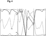
- figure 4 shows the same simulated movement section as in the Figures 1 to 3 , but in a different way.
- the brightness wave W4 from white light color and thus carrier of the overall brightness reacts to the movement in a different ratio than W3 from the RGB model.
- the measurable beginning of the decrease in brightness is not identical in both cases (see figure 4 .t1).
- Wave W2 from the RGB color model only weakly records the simulated movement.
- figure 4 .t2 shows a different start time of the RR interval. The reduction in brightness in the middle of an RR interval can be clearly seen in the overall brightness of wave W4.
- the pulse wave W2 traces the pulse wave without drastic brightness losses or brightness gains.
- figure 4 .t3 makes the different brightnesses, pulse waveforms and timings visible. Thus becomes off figure 4 clearly that in the overall brightness more information is included.
- the waves W1 or W2 or W3 cannot be recognized from the overall brightness wave W4 in a two-dimensional "gray scale" view.
- FIG. 5 Picture 1 shows from the Figure 1 to Figure 4 well-known simulated movement excerpt now in a two-dimensional view.
- the overall brightness display shows how smartphones, wearables and watches are measured using today's state-of-the-art technology.
- Figure 2 shows the different waves from the RGB colors and the color spaces that are constantly being re-adapted to the situations and changes.
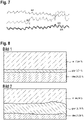
- Figure 1 shows eight unfiltered pulse waves. Each individual color from the split brightnesses of the light reacts differently to pressure, also in relation to the different penetration depths of the colors at the measuring point. Thus, the change in pressure is the main cause of artefacts from the movement. In order to save resources, these pressure changes or movement artifacts can be processed by using special filters.
- Figure 1 shows the vascular jump in wave W2. After filtering in figure 6 In picture 2, the jump was filtered with 0.1 Hz.
- respiratory waves and vascular circuits can be measured separately and, depending on the requirements, displayed and evaluated mathematically or by image or image series.
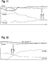
- the figure 7 shows a pulse wave series with two vessel pressure changes/jumps similar to in figure 6 Image 1.
- individual waves and views can be used for more favorable information delivery within pulse waves of an RR interval with the help of frequency splitting.
- the display from the RGB color model shows the influence on the tissue compared to the overall brightness, as well as the resulting split brightness of the light in RGB colors.
- Image 1 indicates low pressure.
- Figure 8 Figure 2
- a high pressure can be determined.
- the measuring point can only show the venous pulse. This is particularly true when the pressure in the lower layers of the skin is maintained for a relatively long period of time due to extreme blood pressure, for example caused by a hanging hand. this is in figure 9 shown.
Landscapes
- Health & Medical Sciences (AREA)
- Life Sciences & Earth Sciences (AREA)
- Cardiology (AREA)
- Biomedical Technology (AREA)
- Medical Informatics (AREA)
- Biophysics (AREA)
- Pathology (AREA)
- Engineering & Computer Science (AREA)
- Physiology (AREA)
- Heart & Thoracic Surgery (AREA)
- Physics & Mathematics (AREA)
- Molecular Biology (AREA)
- Surgery (AREA)
- Animal Behavior & Ethology (AREA)
- General Health & Medical Sciences (AREA)
- Public Health (AREA)
- Veterinary Medicine (AREA)
- Measuring Pulse, Heart Rate, Blood Pressure Or Blood Flow (AREA)
Applications Claiming Priority (3)
| Application Number | Priority Date | Filing Date | Title |
|---|---|---|---|
| DE102015009722 | 2015-07-31 | ||
| DE102015009721.0A DE102015009721A1 (de) | 2015-07-31 | 2015-07-31 | Vorrichtung und Verfahren zur Ermittlung von Helligkeiten und deren Spaltung in Farben |
| PCT/EP2016/068334 WO2017021371A1 (de) | 2015-07-31 | 2016-08-01 | Verfahren und vorrichtung zur nichtinvasiven bestimmung von vitalparametern eines lebenden organismus |
Publications (2)
| Publication Number | Publication Date |
|---|---|
| EP3328271A1 EP3328271A1 (de) | 2018-06-06 |
| EP3328271B1 true EP3328271B1 (de) | 2022-10-05 |
Family
ID=56842782
Family Applications (1)
| Application Number | Title | Priority Date | Filing Date |
|---|---|---|---|
| EP16757829.3A Active EP3328271B1 (de) | 2015-07-31 | 2016-08-01 | Verfahren zur nichtinvasiven bestimmung von vitalparametern eines lebenden organismus |
Country Status (4)
| Country | Link |
|---|---|
| EP (1) | EP3328271B1 (pl) |
| ES (1) | ES2934710T3 (pl) |
| PL (1) | PL3328271T3 (pl) |
| WO (1) | WO2017021371A1 (pl) |
Families Citing this family (3)
| Publication number | Priority date | Publication date | Assignee | Title |
|---|---|---|---|---|
| DE102017002334A1 (de) | 2017-03-13 | 2018-09-13 | Holger Redtel | Zeitaufgelöste Messung von Kenngrößen der Herzfunktion durch autonom verstellbare Meßbereiche, wie z.B. Herzzeitvolumen, Blutdruck, Herzpuls, Pulswellenlaufzeit, Pulswellenvariabilität, Atmungsfrequenz ... |
| DE102017128576A1 (de) | 2017-12-01 | 2019-06-06 | Ilmsens Gmbh | Vorrichtung zur Vitalitätsüberwachung |
| CN111887827A (zh) * | 2020-08-25 | 2020-11-06 | 复旦大学附属中山医院 | 基于拜尔滤镜的多光谱ppg设备及其应用 |
Family Cites Families (4)
| Publication number | Priority date | Publication date | Assignee | Title |
|---|---|---|---|---|
| US8838209B2 (en) * | 2012-02-21 | 2014-09-16 | Xerox Corporation | Deriving arterial pulse transit time from a source video image |
| BR112015006003A2 (pt) * | 2012-09-21 | 2017-07-04 | Koninklijke Philips Nv | dispositivo e método de processamento de dados deriváveis de radiação eletromagnética detectada remotamente, e, programa de computador |
| WO2014072461A1 (de) | 2012-11-11 | 2014-05-15 | Grönemeyer Medical GmbH & Co. KG | Verfahren und vorrichtung zur bestimmung von vitalparametern |
| CN105873503A (zh) * | 2013-12-25 | 2016-08-17 | 旭化成株式会社 | 脉搏波测定装置、便携式设备、医疗设备系统以及生物体信息通信系统 |
-
2016
- 2016-08-01 PL PL16757829.3T patent/PL3328271T3/pl unknown
- 2016-08-01 WO PCT/EP2016/068334 patent/WO2017021371A1/de unknown
- 2016-08-01 ES ES16757829T patent/ES2934710T3/es active Active
- 2016-08-01 EP EP16757829.3A patent/EP3328271B1/de active Active
Also Published As
| Publication number | Publication date |
|---|---|
| WO2017021371A1 (de) | 2017-02-09 |
| ES2934710T3 (es) | 2023-02-24 |
| PL3328271T3 (pl) | 2023-01-23 |
| EP3328271A1 (de) | 2018-06-06 |
Similar Documents
| Publication | Publication Date | Title |
|---|---|---|
| EP2240072B1 (de) | Druckmesser, insbesondere blutdruckmesser, verfahren zur bestimmung von druckwerten, verfahren zum kalibrieren eines druckmessung und computerprogramm zur implementierung dieser verfahren | |
| DE69835843T2 (de) | Pulswellen-Untersuchungsgerät | |
| EP3302231B1 (de) | Verfahren sowie vorrichtung zur ermittlung des verlaufs des blutdrucks | |
| DE102014009439B4 (de) | Vorrichtung und Verfahren zur Verarbeitung von tomografischen Daten | |
| DE19537646C2 (de) | Verfahren und Vorrichtung zum Erkennen verfälschter Meßwerte in der Pulsoximetrie zur Messung der Sauerstoffsättigung | |
| EP1860999B1 (de) | Mobiles diagnosegerät | |
| EP1047987B1 (de) | Verfahren und vorrichtung zur darstellung und überwachung von funktionsparametern eines physiologischen systems | |
| DE102012007081B4 (de) | Verfahren sowie Mess- und Recheneinheit zur langfristigen Überwachung der arteriellen Gefäßsteifigkeit und Gefäßkalzifikation eines Patienten | |
| DE10209027A1 (de) | Blutstromvolumenmessverfahren und Vitalfunktionsüberwachungsvorrichtung | |
| EP3328271B1 (de) | Verfahren zur nichtinvasiven bestimmung von vitalparametern eines lebenden organismus | |
| WO2019180065A1 (de) | Vorrichtung und verfahren zur aufnahme und analyse von bildern der haut | |
| DE112010004170T5 (de) | Pulswellen-Analysevorrichtung und Aufzeichnungsmedium | |
| DE102011114666A1 (de) | Vorrichtung zur hämodynamischen Überwachung | |
| JP4141133B2 (ja) | 周期的データを表示する装置及び方法 | |
| DE102010061580A1 (de) | Verwendung des Frequenzspektrums eines Artefaktes in der Oszillometrie | |
| DE19821761A1 (de) | Verfahren und Vorrichtung zur komprimierten optischen Darstellung medizinischer Daten | |
| DE10117751A1 (de) | Modellierung von Momentanzuständen medizinischer Objekte in Abhängigkeit von zumindest einer Messgröße | |
| DE4238641C2 (de) | Vorrichtung und Arbeitsverfahren zum Bestimmen und Auswerten des physiologischen Zustandes von Gefäßsystemen | |
| EP3592216B1 (de) | Verfahren zum betreiben einer blutdruckmessvorrichtung | |
| EP3796834B1 (de) | Verfahren und vorrichtung zur validierung eines blutdruckmesssystems | |
| EP3316768A1 (de) | Vorrichtung und verfahren zur überwachung und diagnostik des autoregulationsmechanismus des blutdrucks bei einem lebewesen | |
| DE102008039816A1 (de) | Vorrichtung zum kontinuierlichen Messen des arteriellen Blutdrucks und der Herzfrequenz in einem Blutgefäß | |
| DE2405348A1 (de) | Verfahren und vorrichtung zur direkten messung eines mikrokreislaufsystems | |
| DE10319361A1 (de) | Vorrichtung und Verfahren zum Messen der vegetativen Balance | |
| DE102018209198B3 (de) | Verfahren und Gerät zur Bestimmung mindestens eines physiologischen Parameters |
Legal Events
| Date | Code | Title | Description |
|---|---|---|---|
| STAA | Information on the status of an ep patent application or granted ep patent |
Free format text: STATUS: THE INTERNATIONAL PUBLICATION HAS BEEN MADE |
|
| PUAI | Public reference made under article 153(3) epc to a published international application that has entered the european phase |
Free format text: ORIGINAL CODE: 0009012 |
|
| STAA | Information on the status of an ep patent application or granted ep patent |
Free format text: STATUS: REQUEST FOR EXAMINATION WAS MADE |
|
| 17P | Request for examination filed |
Effective date: 20180228 |
|
| AK | Designated contracting states |
Kind code of ref document: A1 Designated state(s): AL AT BE BG CH CY CZ DE DK EE ES FI FR GB GR HR HU IE IS IT LI LT LU LV MC MK MT NL NO PL PT RO RS SE SI SK SM TR |
|
| AX | Request for extension of the european patent |
Extension state: BA ME |
|
| DAV | Request for validation of the european patent (deleted) | ||
| DAX | Request for extension of the european patent (deleted) | ||
| STAA | Information on the status of an ep patent application or granted ep patent |
Free format text: STATUS: EXAMINATION IS IN PROGRESS |
|
| STAA | Information on the status of an ep patent application or granted ep patent |
Free format text: STATUS: EXAMINATION IS IN PROGRESS |
|
| 17Q | First examination report despatched |
Effective date: 20201013 |
|
| STAA | Information on the status of an ep patent application or granted ep patent |
Free format text: STATUS: EXAMINATION IS IN PROGRESS |
|
| RAP1 | Party data changed (applicant data changed or rights of an application transferred) |
Owner name: KENKOU GMBH |
|
| RIN1 | Information on inventor provided before grant (corrected) |
Inventor name: REDTEL, HEIKO |
|
| GRAP | Despatch of communication of intention to grant a patent |
Free format text: ORIGINAL CODE: EPIDOSNIGR1 |
|
| STAA | Information on the status of an ep patent application or granted ep patent |
Free format text: STATUS: GRANT OF PATENT IS INTENDED |
|
| INTG | Intention to grant announced |
Effective date: 20220401 |
|
| GRAS | Grant fee paid |
Free format text: ORIGINAL CODE: EPIDOSNIGR3 |
|
| GRAA | (expected) grant |
Free format text: ORIGINAL CODE: 0009210 |
|
| STAA | Information on the status of an ep patent application or granted ep patent |
Free format text: STATUS: THE PATENT HAS BEEN GRANTED |
|
| AK | Designated contracting states |
Kind code of ref document: B1 Designated state(s): AL AT BE BG CH CY CZ DE DK EE ES FI FR GB GR HR HU IE IS IT LI LT LU LV MC MK MT NL NO PL PT RO RS SE SI SK SM TR |
|
| REG | Reference to a national code |
Ref country code: GB Ref legal event code: FG4D Free format text: NOT ENGLISH |
|
| REG | Reference to a national code |
Ref country code: CH Ref legal event code: EP |
|
| REG | Reference to a national code |
Ref country code: AT Ref legal event code: REF Ref document number: 1522235 Country of ref document: AT Kind code of ref document: T Effective date: 20221015 |
|
| REG | Reference to a national code |
Ref country code: IE Ref legal event code: FG4D Free format text: LANGUAGE OF EP DOCUMENT: GERMAN |
|
| REG | Reference to a national code |
Ref country code: DE Ref legal event code: R096 Ref document number: 502016015333 Country of ref document: DE |
|
| REG | Reference to a national code |
Ref country code: NL Ref legal event code: FP |
|
| REG | Reference to a national code |
Ref country code: LT Ref legal event code: MG9D |
|
| REG | Reference to a national code |
Ref country code: SE Ref legal event code: TRGR |
|
| REG | Reference to a national code |
Ref country code: ES Ref legal event code: FG2A Ref document number: 2934710 Country of ref document: ES Kind code of ref document: T3 Effective date: 20230224 |
|
| PG25 | Lapsed in a contracting state [announced via postgrant information from national office to epo] |
Ref country code: PT Free format text: LAPSE BECAUSE OF FAILURE TO SUBMIT A TRANSLATION OF THE DESCRIPTION OR TO PAY THE FEE WITHIN THE PRESCRIBED TIME-LIMIT Effective date: 20230206 Ref country code: NO Free format text: LAPSE BECAUSE OF FAILURE TO SUBMIT A TRANSLATION OF THE DESCRIPTION OR TO PAY THE FEE WITHIN THE PRESCRIBED TIME-LIMIT Effective date: 20230105 Ref country code: LT Free format text: LAPSE BECAUSE OF FAILURE TO SUBMIT A TRANSLATION OF THE DESCRIPTION OR TO PAY THE FEE WITHIN THE PRESCRIBED TIME-LIMIT Effective date: 20221005 Ref country code: FI Free format text: LAPSE BECAUSE OF FAILURE TO SUBMIT A TRANSLATION OF THE DESCRIPTION OR TO PAY THE FEE WITHIN THE PRESCRIBED TIME-LIMIT Effective date: 20221005 |
|
| PG25 | Lapsed in a contracting state [announced via postgrant information from national office to epo] |
Ref country code: RS Free format text: LAPSE BECAUSE OF FAILURE TO SUBMIT A TRANSLATION OF THE DESCRIPTION OR TO PAY THE FEE WITHIN THE PRESCRIBED TIME-LIMIT Effective date: 20221005 Ref country code: LV Free format text: LAPSE BECAUSE OF FAILURE TO SUBMIT A TRANSLATION OF THE DESCRIPTION OR TO PAY THE FEE WITHIN THE PRESCRIBED TIME-LIMIT Effective date: 20221005 Ref country code: IS Free format text: LAPSE BECAUSE OF FAILURE TO SUBMIT A TRANSLATION OF THE DESCRIPTION OR TO PAY THE FEE WITHIN THE PRESCRIBED TIME-LIMIT Effective date: 20230205 Ref country code: HR Free format text: LAPSE BECAUSE OF FAILURE TO SUBMIT A TRANSLATION OF THE DESCRIPTION OR TO PAY THE FEE WITHIN THE PRESCRIBED TIME-LIMIT Effective date: 20221005 Ref country code: GR Free format text: LAPSE BECAUSE OF FAILURE TO SUBMIT A TRANSLATION OF THE DESCRIPTION OR TO PAY THE FEE WITHIN THE PRESCRIBED TIME-LIMIT Effective date: 20230106 |
|
| P01 | Opt-out of the competence of the unified patent court (upc) registered |
Effective date: 20230508 |
|
| REG | Reference to a national code |
Ref country code: DE Ref legal event code: R097 Ref document number: 502016015333 Country of ref document: DE |
|
| PG25 | Lapsed in a contracting state [announced via postgrant information from national office to epo] |
Ref country code: SM Free format text: LAPSE BECAUSE OF FAILURE TO SUBMIT A TRANSLATION OF THE DESCRIPTION OR TO PAY THE FEE WITHIN THE PRESCRIBED TIME-LIMIT Effective date: 20221005 Ref country code: RO Free format text: LAPSE BECAUSE OF FAILURE TO SUBMIT A TRANSLATION OF THE DESCRIPTION OR TO PAY THE FEE WITHIN THE PRESCRIBED TIME-LIMIT Effective date: 20221005 Ref country code: EE Free format text: LAPSE BECAUSE OF FAILURE TO SUBMIT A TRANSLATION OF THE DESCRIPTION OR TO PAY THE FEE WITHIN THE PRESCRIBED TIME-LIMIT Effective date: 20221005 Ref country code: DK Free format text: LAPSE BECAUSE OF FAILURE TO SUBMIT A TRANSLATION OF THE DESCRIPTION OR TO PAY THE FEE WITHIN THE PRESCRIBED TIME-LIMIT Effective date: 20221005 Ref country code: CZ Free format text: LAPSE BECAUSE OF FAILURE TO SUBMIT A TRANSLATION OF THE DESCRIPTION OR TO PAY THE FEE WITHIN THE PRESCRIBED TIME-LIMIT Effective date: 20221005 |
|
| PLBE | No opposition filed within time limit |
Free format text: ORIGINAL CODE: 0009261 |
|
| STAA | Information on the status of an ep patent application or granted ep patent |
Free format text: STATUS: NO OPPOSITION FILED WITHIN TIME LIMIT |
|
| PG25 | Lapsed in a contracting state [announced via postgrant information from national office to epo] |
Ref country code: SK Free format text: LAPSE BECAUSE OF FAILURE TO SUBMIT A TRANSLATION OF THE DESCRIPTION OR TO PAY THE FEE WITHIN THE PRESCRIBED TIME-LIMIT Effective date: 20221005 Ref country code: AL Free format text: LAPSE BECAUSE OF FAILURE TO SUBMIT A TRANSLATION OF THE DESCRIPTION OR TO PAY THE FEE WITHIN THE PRESCRIBED TIME-LIMIT Effective date: 20221005 |
|
| 26N | No opposition filed |
Effective date: 20230706 |
|
| PGFP | Annual fee paid to national office [announced via postgrant information from national office to epo] |
Ref country code: NL Payment date: 20230821 Year of fee payment: 8 Ref country code: LU Payment date: 20230821 Year of fee payment: 8 |
|
| PGFP | Annual fee paid to national office [announced via postgrant information from national office to epo] |
Ref country code: MC Payment date: 20230823 Year of fee payment: 8 Ref country code: IT Payment date: 20230825 Year of fee payment: 8 Ref country code: IE Payment date: 20230822 Year of fee payment: 8 Ref country code: GB Payment date: 20230822 Year of fee payment: 8 Ref country code: CH Payment date: 20230902 Year of fee payment: 8 Ref country code: AT Payment date: 20230822 Year of fee payment: 8 |
|
| PG25 | Lapsed in a contracting state [announced via postgrant information from national office to epo] |
Ref country code: SI Free format text: LAPSE BECAUSE OF FAILURE TO SUBMIT A TRANSLATION OF THE DESCRIPTION OR TO PAY THE FEE WITHIN THE PRESCRIBED TIME-LIMIT Effective date: 20221005 |
|
| PGFP | Annual fee paid to national office [announced via postgrant information from national office to epo] |
Ref country code: SE Payment date: 20230821 Year of fee payment: 8 Ref country code: PL Payment date: 20230711 Year of fee payment: 8 Ref country code: FR Payment date: 20230825 Year of fee payment: 8 Ref country code: DE Payment date: 20230821 Year of fee payment: 8 Ref country code: BE Payment date: 20230821 Year of fee payment: 8 |
|
| PGFP | Annual fee paid to national office [announced via postgrant information from national office to epo] |
Ref country code: MT Payment date: 20230721 Year of fee payment: 8 |
|
| PGFP | Annual fee paid to national office [announced via postgrant information from national office to epo] |
Ref country code: ES Payment date: 20231027 Year of fee payment: 8 |