EP3328099B1 - Information processing apparatus, control method therefor, and computer program - Google Patents
Information processing apparatus, control method therefor, and computer program Download PDFInfo
- Publication number
- EP3328099B1 EP3328099B1 EP17204193.1A EP17204193A EP3328099B1 EP 3328099 B1 EP3328099 B1 EP 3328099B1 EP 17204193 A EP17204193 A EP 17204193A EP 3328099 B1 EP3328099 B1 EP 3328099B1
- Authority
- EP
- European Patent Office
- Prior art keywords
- state
- communication
- communication means
- information processing
- processing apparatus
- Prior art date
- Legal status (The legal status is an assumption and is not a legal conclusion. Google has not performed a legal analysis and makes no representation as to the accuracy of the status listed.)
- Active
Links
- 238000000034 method Methods 0.000 title claims description 58
- 230000010365 information processing Effects 0.000 title claims description 28
- 238000004590 computer program Methods 0.000 title 1
- 238000004891 communication Methods 0.000 claims description 309
- 230000015654 memory Effects 0.000 claims description 57
- 230000006870 function Effects 0.000 claims description 49
- 230000004044 response Effects 0.000 claims description 20
- 230000008569 process Effects 0.000 description 44
- 230000005540 biological transmission Effects 0.000 description 22
- 238000010586 diagram Methods 0.000 description 21
- 230000007704 transition Effects 0.000 description 11
- 238000005516 engineering process Methods 0.000 description 4
- 230000005674 electromagnetic induction Effects 0.000 description 3
- 239000003990 capacitor Substances 0.000 description 2
- 230000008859 change Effects 0.000 description 2
- 238000013500 data storage Methods 0.000 description 2
- 230000000977 initiatory effect Effects 0.000 description 2
- 239000004973 liquid crystal related substance Substances 0.000 description 2
- 230000003936 working memory Effects 0.000 description 2
- 239000000969 carrier Substances 0.000 description 1
- 230000003111 delayed effect Effects 0.000 description 1
- 230000003287 optical effect Effects 0.000 description 1
- 230000009467 reduction Effects 0.000 description 1
Images


Classifications
-
- H—ELECTRICITY
- H04—ELECTRIC COMMUNICATION TECHNIQUE
- H04M—TELEPHONIC COMMUNICATION
- H04M1/00—Substation equipment, e.g. for use by subscribers
- H04M1/72—Mobile telephones; Cordless telephones, i.e. devices for establishing wireless links to base stations without route selection
- H04M1/724—User interfaces specially adapted for cordless or mobile telephones
- H04M1/72403—User interfaces specially adapted for cordless or mobile telephones with means for local support of applications that increase the functionality
- H04M1/72409—User interfaces specially adapted for cordless or mobile telephones with means for local support of applications that increase the functionality by interfacing with external accessories
- H04M1/72412—User interfaces specially adapted for cordless or mobile telephones with means for local support of applications that increase the functionality by interfacing with external accessories using two-way short-range wireless interfaces
-
- H—ELECTRICITY
- H04—ELECTRIC COMMUNICATION TECHNIQUE
- H04W—WIRELESS COMMUNICATION NETWORKS
- H04W76/00—Connection management
- H04W76/10—Connection setup
-
- H—ELECTRICITY
- H04—ELECTRIC COMMUNICATION TECHNIQUE
- H04W—WIRELESS COMMUNICATION NETWORKS
- H04W36/00—Hand-off or reselection arrangements
- H04W36/34—Reselection control
- H04W36/36—Reselection control by user or terminal equipment
-
- H—ELECTRICITY
- H04—ELECTRIC COMMUNICATION TECHNIQUE
- H04W—WIRELESS COMMUNICATION NETWORKS
- H04W36/00—Hand-off or reselection arrangements
- H04W36/34—Reselection control
- H04W36/36—Reselection control by user or terminal equipment
- H04W36/362—Conditional handover
-
- H—ELECTRICITY
- H04—ELECTRIC COMMUNICATION TECHNIQUE
- H04W—WIRELESS COMMUNICATION NETWORKS
- H04W4/00—Services specially adapted for wireless communication networks; Facilities therefor
- H04W4/80—Services using short range communication, e.g. near-field communication [NFC], radio-frequency identification [RFID] or low energy communication
-
- H—ELECTRICITY
- H04—ELECTRIC COMMUNICATION TECHNIQUE
- H04W—WIRELESS COMMUNICATION NETWORKS
- H04W76/00—Connection management
- H04W76/10—Connection setup
- H04W76/14—Direct-mode setup
-
- H—ELECTRICITY
- H04—ELECTRIC COMMUNICATION TECHNIQUE
- H04W—WIRELESS COMMUNICATION NETWORKS
- H04W88/00—Devices specially adapted for wireless communication networks, e.g. terminals, base stations or access point devices
- H04W88/02—Terminal devices
- H04W88/06—Terminal devices adapted for operation in multiple networks or having at least two operational modes, e.g. multi-mode terminals
-
- H—ELECTRICITY
- H04—ELECTRIC COMMUNICATION TECHNIQUE
- H04W—WIRELESS COMMUNICATION NETWORKS
- H04W80/00—Wireless network protocols or protocol adaptations to wireless operation
-
- H—ELECTRICITY
- H04—ELECTRIC COMMUNICATION TECHNIQUE
- H04W—WIRELESS COMMUNICATION NETWORKS
- H04W84/00—Network topologies
- H04W84/02—Hierarchically pre-organised networks, e.g. paging networks, cellular networks, WLAN [Wireless Local Area Network] or WLL [Wireless Local Loop]
- H04W84/10—Small scale networks; Flat hierarchical networks
- H04W84/12—WLAN [Wireless Local Area Networks]
-
- H—ELECTRICITY
- H04—ELECTRIC COMMUNICATION TECHNIQUE
- H04W—WIRELESS COMMUNICATION NETWORKS
- H04W84/00—Network topologies
- H04W84/18—Self-organising networks, e.g. ad-hoc networks or sensor networks
Description
- The present invention relates to a technology for transmitting and receiving information via wireless communication.
- In recent years, a scheme for setting up communication connections such as wireless local area network (LAN) or Bluetooth (registered trademark) connection with simple operations, called a handover, has been proposed. A handover is a process for switching from a short range communication protocol such as near-field communication (NFC), which devices use to exchange information necessary for authentication, such as configuration information, to a longer range communication protocol such as wireless LAN after such information has been exchanged.
- For example, Japanese Patent Laid-Open No.
2011-151746 - In the technology proposed in Japanese Patent Laid-Open No.
2011-151746 - European patent application No.
2445257 discloses a method comprising initiating, by a first device, an out-of-band short-range carrier transport switch with a second device by transmitting wireless communication signals for providing an out-of-band carrier communication connection, and sending, by the first device, in-band short-range carrier communication connection parameters including one or more parameters indicating a timer value of an interval related to an expected completion time of a transport switch procedure, to the second device via the out-of-band short-range carrier communication connection. - NFC Forum technical specification "Connection Handover" (7 July 2010) discloses a handover negotiation between two devices over near-field communication (NFC), where a device can indicate the power status for each of the proposed or available alternative carriers to a peer device.
- The present invention in its first aspect provides an information processing apparatus as specified in
claims 1 to 10. - The present invention in its second aspect provides a control method as specified in claims 11 to 16.
- The present invention in its third aspect provides a non-transitory storage medium as specified in claim 17.
- Further features of the present invention will become apparent from the following description of exemplary embodiments with reference to the attached drawings.
-
-
Fig. 1 is a diagram illustrating an example of an internal configuration of a communication device according to a first exemplary embodiment of the present invention. -
Fig. 2 is a diagram illustrating an example of the data format of a tag memory according to the first exemplary embodiment of the present invention. -
Fig. 3 is a diagram illustrating an example of an internal configuration of an information terminal according to the first exemplary embodiment of the present invention. -
Fig. 4 is a diagram illustrating an example of a network system configuration according to the first exemplary embodiment of the present invention. -
Fig. 5 is a diagram illustrating the flow of an existing handover process. -
Fig. 6 is a diagram illustrating the flow of a process for storing information in the tag memory according to the first exemplary embodiment of the present invention. -
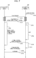
Fig. 7 is a diagram illustrating a processing sequence of a handover process according to the first exemplary embodiment of the present invention. -
Fig. 8 is a diagram illustrating an example of a determination table according to the first exemplary embodiment of the present invention. -
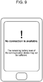
Fig. 9 is a diagram illustrating an example of a failure notification screen according to the first exemplary embodiment of the present invention. -
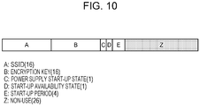
Fig. 10 is a diagram illustrating an example of the data format of a tag memory according to a second exemplary embodiment of the present invention. -
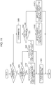
Fig. 11 is a diagram illustrating the flow of a process for storing information in the tag memory according to the second exemplary embodiment of the present invention. -
Fig. 12 is a diagram illustrating a processing sequence of a handover process according to the second exemplary embodiment of the present invention. -
Fig. 13 is a diagram illustrating an example of a determination table according to the second exemplary embodiment of the present invention. -
Fig. 14 is a diagram illustrating an example of a remaining time notification screen according to the second exemplary embodiment of the present invention. -
Fig. 15 is a diagram illustrating another example of the internal configuration of the communication device according to the first exemplary embodiment of the present invention. -
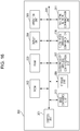
Fig. 16 is a diagram illustrating another example of the internal configuration of the information terminal according to the first exemplary embodiment of the present invention. -
Fig. 17 is a diagram illustrating an example of a determination table according to another exemplary embodiment of the present invention. - Some exemplary embodiments of the present invention will be described in detail hereinafter with reference to the accompanying drawings.
- A first exemplary embodiment of the present invention will be described hereinafter.
-
Fig. 1 is a processing block diagram illustrating an internal configuration of acommunication device 100, which is an example of a communication device according to an exemplary embodiment of the present invention. Examples of the communication device may include a mobile phone, a digital camera, a music player, a tablet terminal, a personal computer, and a mobile access point. As illustrated inFig. 1 , thecommunication device 100 includes acontrol unit 101, a read-only memory (ROM) 102, a random access memory (RAM) 103, adisplay unit 104, anoperation unit 105, astorage unit 106, a close proximitywireless communication unit 107, a close rangewireless communication unit 108, atag memory 110, and a powersupply control unit 111. Thecontrol unit 101, theROM 102, theRAM 103, thedisplay unit 104, theoperation unit 105, thestorage unit 106, the close proximitywireless communication unit 107, and the close rangewireless communication unit 108 are connected to one another via aninternal bus 109 serving as a data transmission path. Thetag memory 110 is included in the close proximitywireless communication unit 107. The powersupply control unit 111 is controlled using thecontrol unit 101, theoperation unit 105, and the close proximitywireless communication unit 107. - The
control unit 101 is a processing block configured to control the overall operation of thecommunication device 100, and is formed of, for example, a central processing unit (CPU). Thecontrol unit 101 executes a program stored in theROM 102, thereby implementing various functions. - The
ROM 102 is a non-volatile memory, and is a memory configured to store data and a processing program to be executed by thecontrol unit 101. - The
RAM 103 is a volatile memory, and is used as a working memory for thecontrol unit 101 or as a temporary data storage area. - The
display unit 104 is a processing block configured to display and output information to a user, and may be formed of, for example, a liquid crystal panel, an organic electroluminescent (EL) panel, or the like. - The
operation unit 105 is a processing block configured to receive an instruction input from the user, and may include buttons, a cross key, a touch panel, and so forth. - The
storage unit 106 is a processing block configured to store and read information in and from a large-capacity recording medium such as a built-in hard disk, a built-in flash memory, or a removable memory card. - The close proximity
wireless communication unit 107 is a processing block configured to perform close proximity wireless communication based on the near-field communication (NFC) protocol which uses the 13.56 MHz frequency band. The close proximitywireless communication unit 107 targets a communication distance of 10 cm or less although the communication distance depends on the environment. The close proximitywireless communication unit 107 includes a resonant circuit including an inductor and a capacitor, a demodulation circuit configured to demodulate a signal received by the resonant circuit, a transmission circuit configured to amplify the carrier and transmit the amplified carrier from the resonant circuit, and so forth. The close proximitywireless communication unit 107 also includes thetag memory 110, and has a function, as an NFC card function, to transmit information stored in thetag memory 110 to an external device having an NFC reader/writer function. The function of the close proximitywireless communication unit 107 is an example of an information transmission unit. In this exemplary embodiment, close proximity wireless communication is implemented using NFC. Any other communication protocol such as Infrared Data Association (IrDA) may be used. -
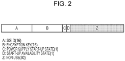
Fig. 2 illustrates an example of the data format of thetag memory 110 according to this exemplary embodiment. As illustrated inFig. 2 , thetag memory 110 has a total capacity of 64 bytes, and is configured to store information concerning a service set identifier (SSID) (16 bytes), an encryption key (16 bytes), a power supply start-up state (1 byte), and a start-up availability state (1 byte). The SSID and encryption key are information necessary to connect to a wireless LAN network, which is configured by the close rangewireless communication unit 108 described below. The power supply start-up state is information indicating the power supply start-up state of thecommunication device 100. In this exemplary embodiment, three types of power supply start-up states are defined: "0: On-state (normal mode)", "1: On-state (energy-saving mode)", and "2: Off-state". The state "0: On-state (normal mode)" is a state where all the function blocks of thecommunication device 100 are in operation, and indicates that, for example, thecommunication device 100 is being operated by a user. The state "1: On-state (energy-saving mode)" is a state where some of the function blocks are in operation, and corresponds to, for example, a standby mode in which thecommunication device 100 is maintained powered up but is not being operated by a user. In this state, the access point function of the close rangewireless communication unit 108, described below, is not started. The state "2: Off-state" is a state where thecommunication device 100 stays powered off. The start-up availability state is information indicating whether or not thecommunication device 100 is ready to enter from the "2: Off-state" state to the "0: On-state (normal mode)" or "1: On-state (energy-saving mode)" state, and is either "0: Available" or "1: Not available". The start-up availability state is information which is valid only when the power supply start-up state is "2: Off-state". For example, if thecommunication device 100, which is battery driven, has no battery remaining and the power supply start-up state is "2: Off-state", the start-up availability state is "1: Not available". The above power supply start-up states are examples of a plurality of operation modes. - The read and write operation of the
tag memory 110 described above may be performed using thecontrol unit 101 and also using an external device having the NFC reader/writer function via close proximity wireless communication. In the case of close proximity wireless communication with an external device, control is executed by using the electric power generated by electromagnetic induction when radio waves supplied from the external device are received. Therefore, the read and write operation may be performed using an external device even while thecommunication device 100 is in a power-off state. - Referring back to
Fig. 1 , the close rangewireless communication unit 108 is a processing block configured to perform wireless LAN communication based on the Institute of Electrical and Electronics Engineers (IEEE) 802.11 protocol, which is longer range communication than the communication performed by the close proximitywireless communication unit 107. The close rangewireless communication unit 108 includes a baseband/media access control (MAC) controller circuit, a radio-frequency (RF) module, an antenna, and so forth. The close rangewireless communication unit 108 has an access point function to self-configure a wireless LAN network, and receives a wireless LAN connection request from an external device having a station function. The close rangewireless communication unit 108 may not necessarily be a wireless LAN communication unit, and may be based on, for example, Bluetooth (registered trademark). - The power
supply control unit 111 is a block configured to control the supply of battery power to the entirety of thecommunication device 100, and is controlled using thecontrol unit 101, theoperation unit 105, and the close proximitywireless communication unit 107. Specifically, if the remaining battery level is lower than a certain threshold value, power-off processing is executed by thecontrol unit 101. If power supply processing is executed by the user operating a power supply button, control is executed in accordance with an input signal from theoperation unit 105. If power-on processing is executed using an external device via close proximity wireless communication based on the NFC protocol, control is executed in accordance with a signal from the close proximitywireless communication unit 107. -
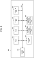
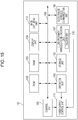
Fig. 3 is a processing block diagram illustrating an internal configuration of aninformation terminal 300, which is an example of an information terminal according to an exemplary embodiment of the present invention. Examples of the information terminal may include a mobile phone, a digital camera, a music player, a tablet terminal, and a personal computer. As illustrated inFig. 3 , theinformation terminal 300 includes acontrol unit 301, aROM 302, aRAM 303, adisplay unit 304, anoperation unit 305, astorage unit 306, a close proximitywireless communication unit 307, and a close rangewireless communication unit 308. The above components are connected to one another via aninternal bus 309 serving as a data transmission path. - The
control unit 301 is a processing block configured to control the overall operation of theinformation terminal 300, and is formed of, for example, a CPU. Thecontrol unit 301 executes a program stored in theROM 302, thereby implementing various functions. - The
ROM 302 is a non-volatile memory, and is a memory configured to store data and a processing program to be executed by thecontrol unit 301. - The
RAM 303 is a volatile memory, and is used as a working memory for thecontrol unit 301 or as a temporary data storage area. - The
display unit 304 is a processing block configured to display and output information to a user, and may be formed of, similarly to thedisplay unit 104 of thecommunication device 100, for example, a liquid crystal panel, an organic EL panel, or the like. - The
operation unit 305 is a processing block configured to receive an instruction input from the user, and may include, similarly to thedisplay unit 104 of thecommunication device 100, buttons, a cross key, a touch panel, and so forth. - The
storage unit 306 is a processing block configured to store and read information in and from a large-capacity recording medium such as a built-in hard disk, a built-in flash memory, or a removable memory card. - The close proximity
wireless communication unit 307 is a processing block configured to perform close proximity wireless communication based on the NFC protocol. The close proximitywireless communication unit 307 includes a resonant circuit including an inductor and a capacitor, a demodulation circuit configured to demodulate a signal received by the resonant circuit, a transmission circuit configured to amplify the carrier and transmit the amplified carrier from the resonant circuit, and so forth. The close proximitywireless communication unit 307 has an NFC reader/writer function to implement a function to read information from an external device having an NFC card function. This function is an example of an information reception unit. - The close range
wireless communication unit 308 is a processing block configured to perform wireless LAN communication based on the IEEE 802.11 protocol. The close rangewireless communication unit 308 includes a baseband/MAC controller circuit, an RF module, an antenna, and so forth. The close rangewireless communication unit 308 has a station function to connect to a wireless LAN network configured by an access point. -
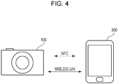
Fig. 4 is a diagram schematically illustrating an example of a network system according to this exemplary embodiment. In this exemplary embodiment, a description will be given of a system in which wireless communication connection is established between a communication device and an information terminal, where, by way of example, the communication device is a digital camera and the information terminal is a mobile phone. As illustrated inFig. 4 , a network system includes thecommunication device 100 and theinformation terminal 300, and thecommunication device 100 and theinformation terminal 300 are configured to communicate with each other via close proximity wireless communication based on the NFC protocol. The close proximity wireless communication based on the NFC protocol is an example of a second wireless communication protocol. Thecommunication device 100 and theinformation terminal 300 are also configured to communicate with each other via close range wireless communication based on the wireless LAN protocol. The close range wireless communication based on the wireless LAN protocol is an example of a first wireless communication protocol. In this case, thecommunication device 100 described with reference toFig. 1 further includes an image capturing unit 112 (seeFig. 15 ). Theimage capturing unit 112 converts object light focused by a lens into an electrical signal, performs processing such as noise reduction, and outputs digital data as image data. Theinformation terminal 300 described with reference toFig. 3 further includes animage capturing unit 310 and a telephonenetwork communication unit 311 for accessing a mobile phone network (Fig. 16 ). - As described above, in the NFC protocol, communication is executed in such a way that the
information terminal 300 having a reader/writer function reads information stored in thetag memory 110 of thecommunication device 100 having a card function. - In the wireless LAN protocol, by contrast, the
communication device 100 has an access point function, and communication is executed in such a way that theinformation terminal 300 having a station function connects to a wireless LAN network configured by thecommunication device 100 in an infrastructure mode. - In
Fig. 4 , a digital camera is used as a communication device and a smartphone is used as an information terminal, by way of example. This example does not limit a system configuration to which the present invention is applicable. - The flow of an existing handover process, which is executed in the network configuration illustrated in
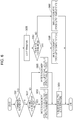
Fig. 4 , will now be briefly described with reference toFig. 5 . The following description is based on the assumption that the power of thecommunication device 100 and theinformation terminal 300 stay powered on. - As illustrated in the upper portion of
Fig. 5 , before the initiation of a handover, wireless LAN parameter information (SSID, encryption key) for connecting to a wireless LAN network configured by using the access point function of thecommunication device 100 is stored in the tag memory 110 (S501). The processing of S501 may be performed through an input operation performed by the user using theoperation unit 105, or may be automatically performed by means of thecontrol unit 101 of thecommunication device 100. - After the above operation has been performed, when the user brings the
information terminal 300 into close proximity to thecommunication device 100, NFC-based close proximity wireless communication is executed, and the wireless LAN parameter information stored in thetag memory 110 is transmitted to the information terminal 300 (S502). Then, theinformation terminal 300 transmits a communication connection request to the wireless LAN network associated with the SSID included in the wireless LAN parameter information received in S501 (S503). - Thereafter, upon receiving the communication connection request, the
communication device 100 transmits a response indicating permission of the request to the information terminal 300 (S504). Accordingly, wireless LAN communication connection is established between thecommunication device 100 and theinformation terminal 300. Through the thus established wireless LAN communication, for example, image data obtained by capturing an image using a digital camera can be transmitted to a mobile phone. Alternatively, through the wireless LAN communication, image data obtained by capturing an image using a mobile phone can be transmitted to a digital camera. The image data to be transmitted and received may be selected by the device on the transmitter side or may be selected by the device on the receiver side. - The flow of the existing handover process has been described. This procedure may eliminate the need for user input of parameters for establishing wireless LAN communication connection, and facilitate the setup of an environment where image data can be exchanged via wireless LAN communication. Here, data to be exchanged via wireless LAN communication is image data, by way of example, for ease of description. However, this is merely an example. For example, data to be exchanged via wireless LAN communication may be moving image data or audio data. Note that NFC-based close proximity wireless communication has a lower communication speed than wireless LAN communication. For this reason, in this exemplary embodiment, it is basically assumed that image data itself is transmitted and received via wireless LAN communication. However, comparatively small size data such as metadata attached to the image data and thumbnails may be transmitted and received via NFC-based close proximity wireless communication.
- A description has been given of the configuration of the
communication device 100 and theinformation terminal 300 and the network system configuration according to this exemplary embodiment. A handover process according to the present invention in the above-described configuration will now be described with reference to the drawings. - First, a process for storing information in the
tag memory 110 of thecommunication device 100 according to this exemplary embodiment will be described with reference toFig. 6 . This process is an example of a process performed by a storage unit. - The process is based on the assumption that wireless LAN parameter information (SSID, encryption key) for connecting to a wireless LAN network configured by using the access point function of the close range
wireless communication unit 108 is stored in thetag memory 110 in advance. - The processing flow illustrated in
Fig. 6 is executed at the time when the power supply start-up state of thecommunication device 100 is changed. As described above, in this exemplary embodiment, the power supply start-up state is any of "0: On-state (normal mode)", "1: On-state (energy-saving mode)", and "2: Off-state". The illustrated process starts when, for example, the power of thecommunication device 100 is turned on or, conversely, the power of thecommunication device 100 is turned off in accordance with a user operation. The illustrated process is also executed when, in the power-on state, the mode is changed from the normal mode to the energy-saving mode. - In S601, the
control unit 101 determines whether the change of the power supply start-up state indicates that the power of thecommunication device 100 is turned off. If the determination is YES, the process proceeds to S602. If the determination is NO, the process proceeds to S606. The determination may be YES when, for example, a transition to "2: Off-state" has occurred in response to a power-off operation performed by the user or when an automatic transition to "2: Off-state" has occurred since the remaining battery level is less than a certain threshold value. The determination may be NO when, for example, a transition to "0: On-state (normal mode)" has occurred in response to a power-on operation performed by the user. Other examples include a case where a transition to "1: On-state (energy-saving mode)" has occurred since no user operation has been performed for a certain period of time, and a case where a transition to "0: On-state (normal mode)" has occurred in response to a user operation performed in the energy-saving mode. - In S602, the
control unit 101 determines whether it is possible to turn on the power of thecommunication device 100 after thecommunication device 100 has entered the power-off state. This determination process is based on the remaining battery level of thecommunication device 100. If the determination is YES, the process proceeds to S603. If the determination is NO, the process proceeds to S605. For example, in a case where an automatic transition to "2: Off-state" has occurred since the remaining battery level is less than a certain threshold value, the determination is NO. - In S603, the
control unit 101 updates the information concerning the power supply start-up state and start-up availability state in thetag memory 110. In S603, the power supply start-up state is set to "2: Off-state" and the start-up availability state is set to "0: Available". - In S604, the
control unit 101 turns off the power supply to thecommunication device 100. Then, the process ends. - If NO is determined in S602, in S605, the
control unit 101 updates the information concerning the power supply start-up state and start-up availability state in thetag memory 110. In S605, the power supply start-up state is set to "2: Off-state" and the start-up availability state is set to "1: Not available". - If NO is determined in S601, then in S606, the
control unit 101 executes a transition to a specified power supply start-up state. - In S607, the
control unit 101 determines whether the change of the power supply start-up state indicates a transition to the power-on state in the normal mode or a transition to the power-on state in the energy-saving mode. If a transition to the normal mode is determined (YES), the process proceeds to S608. If a transition to the energy-saving mode is determined (NO), the process proceeds to S609. - In S608, the
control unit 101 updates the information concerning the power supply start-up state in thetag memory 110. In S608, the power supply start-up state is set to "0: On-state (normal mode)". - In S609, the
control unit 101 updates the information concerning the power supply start-up state in thetag memory 110. In S609, the power supply start-up state is set to "1: On-state (energy-saving mode)". - The information storage process for the
tag memory 110 has been described. - As described above, the description is based on the assumption that wireless LAN parameter information (SSID, encryption key) is stored in the
tag memory 110 in advance. For example, fixed wireless LAN parameter information may instead be written to thetag memory 110 before factory shipment. Alternatively, a setting menu screen may be displayed on thedisplay unit 104, and the wireless LAN parameter information in thetag memory 110 may be updated at the time when the network settings for the wireless LAN are changed in accordance with an input operation performed by the user using theoperation unit 105. - The details of the handover process executed between the
communication device 100 and theinformation terminal 300 according to this exemplary embodiment will now be described with reference to the drawings. - Herein, in a typical processing sequence according to the present invention, by way of example, the power supply start-up state of the
communication device 100 is "2: Off-state", and the start-up availability state of thecommunication device 100 is "0: Available". A processing sequence to be performed when the handover process is initiated in the above conditions will be described with reference toFig. 7 . An example of the other power supply start-up states and start-up availability states will be described below. - In S701, the
control unit 301 of theinformation terminal 300 enables the NFC reader/writer function in accordance with a user operation. The NFC reader/writer function may be enabled by, for example, the pressing of a certain button of theoperation unit 305. - In S702, the
control unit 301 of theinformation terminal 300 transmits a read request signal by using the reader/writer function of the close proximitywireless communication unit 307. The processing of S702 is executed in response to theinformation terminal 300 and thecommunication device 100 being brought into close proximity within the communication range for NFC communication by the user. The communication range of the NFC protocol is a range with a close distance of approximately 10 cm. For example, a screen for prompting the user to bring theinformation terminal 300 into close proximity to the communication device 100 (or to cause theinformation terminal 300 to touch the communication device 100) is displayed on thedisplay unit 304 of theinformation terminal 300. When the user causes theinformation terminal 300 to touch thecommunication device 100, a read request signal transmitted from the close proximitywireless communication unit 307 arrives at the close proximitywireless communication unit 107 of thecommunication device 100. InFig. 7 , shaded areas on the vertical axes indicate that the respective devices are in close proximity within the communication range for NFC communication. The read request is an example of an information acquisition request. - In S703, the close proximity
wireless communication unit 107 of thecommunication device 100 reads information stored in thetag memory 110, and transmits the read information to theinformation terminal 300 as a response signal to the read request signal. The information to be transmitted here includes wireless LAN parameter information (SSID, encryption key) for connecting to a wireless LAN network configured by using the access point function of the close rangewireless communication unit 108 of thecommunication device 100. The information also includes the information concerning the power supply start-up state ("2: Off-state") and the start-up availability state ("0: Available"). The processing of S703 is executed while thecommunication device 100 is in a power-off state. The close proximitywireless communication unit 107 of thecommunication device 100 executes processing by using the electric power generated by electromagnetic induction when receiving radio waves supplied from the close proximitywireless communication unit 307 of theinformation terminal 300. - After S703, the processing (S704) of the
communication device 100 and the processing (S705) of theinformation terminal 300 are started in parallel. - In S704, the close proximity
wireless communication unit 107 of thecommunication device 100 controls the powersupply control unit 111 to enable the supply of battery power to thecommunication device 100 to start the overall system of thecommunication device 100. In addition to this, the close proximitywireless communication unit 107 requests thecontrol unit 101 to enable the close rangewireless communication unit 108. Upon receiving this request, thecontrol unit 101 enables the access point function of the close rangewireless communication unit 108. The processing of S704 is an example of a process performed by an enabling unit. - In S705, the
control unit 301 of theinformation terminal 300 analyzes the information received in S703, and determines the transmission timing condition under which a communication connection request is transmitted by the close rangewireless communication unit 308. Specifically, thecontrol unit 301 refers to a determination table included in advance in theinformation terminal 300 on the basis of the acquired information concerning the start-up availability state and the power supply start-up state to determine whether or not a communication connection request is to be transmitted from the close rangewireless communication unit 308 and to determine the transmission timing condition if a communication connection request is to be transmitted. The processing of S705 is an example of a process performed by a determination unit. -
Fig. 8 illustrates an example of a determination table according to this exemplary embodiment. As illustrated inFig. 8 , the determination table contains information associated with the acquired information on the start-up availability state and the power supply start-up state, which includes availability of transmission of a communication connection request, a waiting period, and the number of retries. The availability of transmission indicates whether or not theinformation terminal 300 will transmit a communication connection request from the close rangewireless communication unit 308 after S705. The waiting period indicates a waiting period from the time when the processing of S705 is performed to the time when theinformation terminal 300 transmits a communication connection request through the close rangewireless communication unit 308. The number of retries indicates the maximum number of retransmission attempts of a communication connection request from the close rangewireless communication unit 308. In the illustrated example of the processing sequence, since the power supply start-up state is "2: Off-state" and the start-up availability state is "0: Available", the transmission conditions of No. 3 are determined. - Referring back to
Fig. 7 , in S706, thecontrol unit 301 of theinformation terminal 300 waits for a certain period of time in accordance with a waiting period condition in the transmission timing condition determined in S705. In a case where the station function of the close rangewireless communication unit 308 is not enabled, thecontrol unit 301 may start the station function. - In S707, the
control unit 301 of theinformation terminal 300 controls the close rangewireless communication unit 308 to transmit a communication connection request to thecommunication device 100 in order to connect to a wireless LAN network configured by using the access point function of the close rangewireless communication unit 108 of thecommunication device 100. The processing of S707 corresponds to a connection request unit according to the present invention. In the illustrated example, the wireless LAN parameter information (SSID, encryption key) acquired in S703 is used. Herein, as illustrated inFig. 7 , the access point function of the close rangewireless communication unit 108 of thecommunication device 100 is still being started and is not yet enabled when the processing of S707 is executed. Thus, no response is made to the communication connection request transmitted in S707. - In S708, the
control unit 301 of theinformation terminal 300 determines that a timeout has occurred because no response to the communication connection request transmitted in S707 is made from thecommunication device 100 for a certain period of time. The timeout period may be 500 ms, 1 sec, or the like. - In S709, the
control unit 301 of theinformation terminal 300 re-transmits the communication connection request to thecommunication device 100 in accordance with a number-of-retries condition in the transmission timing condition determined in S705. Since the access point function of the close rangewireless communication unit 108 of thecommunication device 100 is enabled at this time, the transmitted communication connection request is received by thecommunication device 100. - In S710, the
control unit 101 of thecommunication device 100 determines that the wireless LAN parameter information (SSID, encryption key) transmitted in S709 is valid, and controls the close rangewireless communication unit 108 to transmit a response indicating permission of the communication connection request to theinformation terminal 300. Accordingly, wireless LAN communication connection is established between thecommunication device 100 and theinformation terminal 300. The processing of S710 is an example of a process performed by a connection request response unit. - The details of the handover process executed between the
communication device 100 and theinformation terminal 300 according to this exemplary embodiment have been described with reference toFig. 7 . - An example of the power supply start-up states and the start-up availability states other than those of No. 3 in
Fig. 8 will now be described. In the example for No. 1, since all the function blocks of thecommunication device 100 are in operation and the duration of processing in step S704 is very short, the waiting period is 0 seconds (or a duration of several hundreds of milliseconds). Thus, the processing of S706 on theinformation terminal 300 side is omitted. In the example of No. 2, since the access point function of the close rangewireless communication unit 108 needs to be started, the duration of processing in S704 is longer than for No. 1. However, the duration of processing in S704 is shorter than that for No. 3 where all the processing blocks need to be started. Thus, the waiting period (S706) is 3 seconds between the waiting periods for No. 1 and No. 3. In the example of No. 4, since the start up of thecommunication device 100 is not available, in S705, a screen indicating that the handover process has failed is presented to the user. Then, the handover process ends. The processing of S704 and the steps after S706 is not executed.Fig. 9 illustrates an example of the failure notification screen presented to the user on thedisplay unit 304. An example of the power supply start-up states and the start-up availability states other than those for No. 3 has been described. - The exemplary embodiment described above enables the
information terminal 300 to be controlled not to transmit a communication connection request for a wireless LAN as much as possible while thecommunication device 100 is starting the access point function of the close rangewireless communication unit 108. In addition, in a case where the start up of thecommunication device 100 is not possible, theinformation terminal 300 may be controlled not to transmit a communication connection request for a wireless LAN. Accordingly, theinformation terminal 300 may execute transmission control of a communication connection request for a wireless LAN at an optimum time in the handover process. - In this exemplary embodiment, in order to turn on the power of the
communication device 100 that is in a power-off state via close proximity wireless communication based on the NFC protocol, thetag memory 110 whose read and write operation is enabled only by the electric power of theinformation terminal 300 is included in thecommunication device 100. However, thetag memory 110 is not essential to the present invention. In a case where the power supply start-up state of thecommunication device 100, which is in the energy-saving mode, is changed to the normal mode via close proximity wireless communication based on the NFC protocol, the close proximitywireless communication unit 107 of thecommunication device 100 may merely have an NFC card emulation function and thecontrol unit 101 stores an SSID, an encryption key, a power supply start-up state, and a start-up availability state, instead of thetag memory 110 and responds to access from thecommunication device 100. Alternatively, both thecommunication device 100 and theinformation terminal 300 may have an NFC peer-to-peer (P2P) function and thecontrol unit 101 stores an SSID, an encryption key, a power supply start-up state, and a start-up availability state, instead of thetag memory 110 and responds to access from thecommunication device 100. - A second exemplary embodiment of the present invention will now be described.
- In the first exemplary embodiment, by way of example, the
communication device 100 stores wireless LAN parameter information (SSID, encryption key) and information concerning the power supply start-up state and the start-up availability state in thetag memory 110. In this exemplary embodiment, start-up period information (4 bytes) is further stored, and theinformation terminal 300 determines the transmission condition for a communication connection request for close range wireless communication in accordance with the stored start-up period information. - Components having substantially the same functional configurations as those in the first exemplary embodiment are assigned the same numerals to avoid redundant description, and characteristic portions of the second exemplary embodiment will be described in detail.
- The internal configuration of the
communication device 100 and theinformation terminal 300 and the network system configuration according to this exemplary embodiment are similar to those in the first exemplary embodiment, and a description thereof is thus omitted. -
Fig. 10 illustrates an example of the data format of thetag memory 110 according to this exemplary embodiment. As illustrated inFig. 10 , thetag memory 110 has a total capacity of 64 bytes, and is configured to store information concerning an SSID (16 bytes), an encryption key (16 bytes), a power supply start-up state (1 byte), a start-up availability state (1 byte), and a start-up period (4 bytes). The SSID, the encryption key, the power supply start-up state, and the start-up availability state have been described in the first exemplary embodiment. The start-up period is information concerning the time period from the time when information in thetag memory 110 is transmitted to an external device via close proximity wireless communication to the time when the close rangewireless communication unit 108 is enabled (or is ready to make a response). The start-up period corresponds to the time period required in S704 in the sequence diagram illustrated inFig. 7 . - A process for storing information in the
tag memory 110 of thecommunication device 100 according to this exemplary embodiment will now be described with reference toFig. 11 . The following description will be given of only processing steps different from those in the storage process according to the first exemplary embodiment illustrated inFig. 6 . - In S1101, the
control unit 101 updates the information concerning the power supply start-up state, start-up availability state, and start-up period in thetag memory 110. In S1101, the power supply start-up state is set to "2: Off-state", the start-up availability state is set to "0: Available", and the start-up period is set to "7 seconds". - In S1102, the
control unit 101 updates the information concerning the power supply start-up state and start-up period in thetag memory 110. In S1102, the power supply start-up state is set to "0: On-state (normal mode)" and the start-up period is set to "0 seconds". - In S1103, the
control unit 101 updates the information concerning the power supply start-up state and start-up period in thetag memory 110. In S1103, the power supply start-up state is set to "1: On-state (energy-saving mode)" and the start-up period is set to "1 second". - The information storage process for the
tag memory 110 according to this exemplary embodiment has been described. - The details of the handover process executed between the
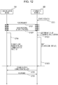
communication device 100 and theinformation terminal 300 according to this exemplary embodiment will now be described with reference toFig. 12 . The following description will be given of only processing steps different from those in the handover process according to the first exemplary embodiment illustrated inFig. 7 . - In S1201, the close proximity
wireless communication unit 107 of thecommunication device 100 reads information stored in thetag memory 110, and transmits the read information to theinformation terminal 300 as a response signal to the read request signal. The information to be transmitted here includes wireless LAN parameter information (SSID, encryption key) for connecting to a wireless LAN network configured by using the access point function of the close rangewireless communication unit 108 of thecommunication device 100. The information also includes the information concerning the power supply start-up state ("2: Off-state"), the information concerning the start-up availability state ("0: Available"), and the start-up period information ("7 seconds"). The processing of S1201 is executed while thecommunication device 100 is in a power-off state. The close proximitywireless communication unit 107 of thecommunication device 100 executes processing by using the electric power generated by electromagnetic induction when receiving radio waves supplied from the close proximitywireless communication unit 307 of theinformation terminal 300. - After S1201, the processing (S704) of the
communication device 100 and the processing (S1202) of theinformation terminal 300 are started in parallel. - In S1202, the
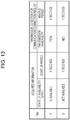
control unit 301 of theinformation terminal 300 analyzes the information received in S1201, and determines the transmission timing condition under which a communication connection request is transmitted by the close rangewireless communication unit 308. Specifically, thecontrol unit 301 refers to a determination table included in advance in theinformation terminal 300 on the basis of the acquired information concerning the start-up availability state and the start-up period to determine whether or not a communication connection request is to be transmitted from the close rangewireless communication unit 308 and to determine the transmission timing condition if a communication connection request is to be transmitted.Fig. 13 illustrates an example of the determination table according to this exemplary embodiment. As illustrated inFig. 13 , the determination table contains information associated with the acquired information concerning the start-up availability state and the start-up period, which includes availability of transmission of a communication connection request and a waiting period. The availability of transmission indicates whether or not theinformation terminal 300 will transmit a communication connection request from the close rangewireless communication unit 308 after S1202. The waiting period indicates a waiting period from the time when the processing of S1202 is performed to the time when theinformation terminal 300 transmits a communication connection request through the close rangewireless communication unit 308. In the illustrated example of the processing sequence, since the start-up availability state is "0: Available" and the start-up period is "7 seconds", the transmission conditions of No. 1 are determined, and the waiting period is determined to be "7 seconds". - In S1203, the
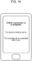
control unit 301 of theinformation terminal 300 waits for a certain period of time in accordance with a waiting period condition in the transmission timing condition determined in S1202. In a case where the station function of the close rangewireless communication unit 308 is not enabled, thecontrol unit 301 may start the station function. In addition, an indication of start up from the power-off state and the remaining waiting period may be displayed on thedisplay unit 304 to notify the user of the time when communication connection based on a wireless LAN will be established.Fig. 14 illustrates an example of the remaining time notification screen displayed on thedisplay unit 304. Thecontrol unit 301 of theinformation terminal 300 may count down the remaining time on the screen and notify the user of the remaining time in real time. - The details of the handover process executed between the
communication device 100 and theinformation terminal 300 according to this exemplary embodiment have been described with reference toFig. 12 . - The exemplary embodiment described above enables the
information terminal 300 to be controlled to transmit a communication connection request for a wireless LAN in accordance with the time when thecommunication device 100 completes the start up of the access point function of the close rangewireless communication unit 108. In addition, a user may also be notified of the remaining time of the waiting period. Accordingly, theinformation terminal 300 may execute transmission control of a communication connection request for a wireless LAN at an optimum time in the handover process. - According to the present invention, a procedure for establishing communication may be performed at an appropriate time.
- In the foregoing exemplary embodiments, a description has been given of an example in which the start time of the transmission of a connection request is delayed and the number of retries of a connection request is increased to extend the time taken for the
information terminal 300 to determine that connection with thecommunication device 100 is not possible, thereby making the time required for thecommunication device 100 to complete the start up of the access point function. This is merely an example. For example, the timeout period may be changed based on the power supply start-up state and start-up availability state obtained from thecommunication device 100 via close proximity wireless communication. In this case, a table (Fig. 17 ) obtained by adding the timeout periods corresponding to the respective power supply start-up states and start-up availability states to the table illustrated inFig. 8 is recorded in advance. The table illustrated inFig. 17 may be referred to, thereby implementing appropriate setting of the timeout period. - Embodiments of the present invention can also be realized by a computer of a system or apparatus that reads out and executes computer executable instructions recorded on a storage medium (e.g., non-transitory computer-readable storage medium) to perform the functions of one or more of the above-described embodiment(s) of the present invention, and by a method performed by the computer of the system or apparatus by, for example, reading out and executing the computer executable instructions from the storage medium to perform the functions of one or more of the above-described embodiment(s). The computer may comprise one or more of a central processing unit (CPU), micro processing unit (MPU), or other circuitry, and may include a network of separate computers or separate computer processors. The computer executable instructions may be provided to the computer, for example, from a network or the storage medium. The storage medium may include, for example, one or more of a hard disk, a random-access memory (RAM), a read only memory (ROM), a storage of distributed computing systems, an optical disk (such as a compact disc (CD), digital versatile disc (DVD), or Blu-ray Disc (BD)™), a flash memory device, a memory card, and the like.
Claims (17)
- An information processing apparatus (100) comprising:control means (101) for checking a power supply start-up state of the information processing apparatus;first communication means (108) for establishing a wireless communication with an external apparatus (300); andsecond communication means (107) for communicating with the external apparatus (300) via a close proximity wireless communication;wherein the second communication means (107) is configured to receive a request from the external apparatus (300) when the external apparatus is in close proximity to the information processing apparatus (100);wherein the second communication means (107) is configured to transmit, in response to the request from the external apparatus (300), time information based on the power supply start-up state to the external apparatus (300) ;wherein the time information indicates a time required for the information processing apparatus (100) to reach a state in which the information processing apparatus can receive an access request from the external apparatus (300) using the first communication means (108).
- The information processing apparatus according to claim 1,
wherein the second communication means (107) includes a tag memory (110) accessible from the control means (101) and accessible from the external apparatus (300),
wherein the tag memory (110) stores a communication parameter which is used for establishing the wireless communication between the information processing apparatus (100) and the external apparatus (300). - The information processing apparatus according to any preceding claim, wherein the power supply start-up state includes one of a standby state and a normal state.
- The information processing apparatus according to claim 3, wherein time information which is written in the tag memory (110) by the control means (101) in response to the power supply start-up state changing to the standby state indicates a longer time than time information which is written in the tag memory by the control means in response to the power supply start-up state changing to the normal state.
- The information processing apparatus according to any preceding claim, wherein the second communication means (107) receives external power wirelessly from the external apparatus (300) and runs using the external power.
- The information processing apparatus according to any preceding claim, wherein the second communication means (107) is capable of operating without an instruction from the control means (101) even if the control means is in an Off-state.
- The information processing apparatus according to any preceding claim, wherein, in addition to the time information, the second communication means (107) further transmits, to the external apparatus (300), information whether start-up of the information processing apparatus (100) is available.
- The information processing apparatus according to any preceding claim, wherein a communication range of the second communication means (107) is narrower than a communication range of the first communication means (108).
- The information processing apparatus according to any preceding claim, wherein a communication speed of the second communication means (107) is slower than a communication speed of the first communication means (108).
- The information processing apparatus according to any preceding claim,
wherein the first communication means (108) includes an access point function, and
wherein the control means (101) activates the access point function of the first communication means (108) in response to the request from the external apparatus (300) received via the second communication means (107). - A control method for an information processing apparatus (100) which has first communication means (108) for establishing a wireless communication with an external apparatus (300) and second communication means (107) for communicating with the external apparatus (300) via a close proximity wireless communication, the method comprising:checking a power supply start-up state of the information processing apparatus;receiving a request from the external apparatus (300) when the external apparatus is in close proximity to the information processing apparatus (100);transmitting, in response to the request from the external apparatus (300), time information based on the power supply start-up state to the external apparatus by the second communication means (107),wherein the time information indicates a time required for the information processing apparatus (100) to reach a state in which the information processing apparatus can receive an access request from the external apparatus (300) using the first communication means (108).
- The control method according to claim 11, wherein the second communication means (107) is capable of operating without an instruction from a control means (101) even if the control means is in an Off-state.
- The control method according to claim 11 or 12, wherein in a case where the time information is transmitted by the second communication means (107), information on whether start-up of the information processing apparatus (100) is available is further transmitted to the external apparatus (300), in addition to the time information.
- The control method according to any of claims 11 to 13, wherein a communication range of the second communication means (107) is narrower than a communication range of the first communication means (108).
- The control method according to any of claims 11 to 14, wherein a communication speed of the second communication means (107) is slower than a communication speed of the first communication means (108).
- The control method according to any of claims 11 to 15,
wherein the first communication means (108) includes an access point function, and
wherein the access point function of the first communication means is activated in response to a request from the external apparatus (300) received via the second communication means (107). - A non-transitory storage medium that stores a program for causing a computer which has first communication means (108) for establishing a wireless communication with an external apparatus (300) and second communication means (107) for communicating with the external apparatus (300) via a close proximity wireless communication, to execute the following steps:checking a power supply start-up state of the information processing apparatus (100);receiving a request from the external apparatus (300) when the external apparatus is in close proximity to the information processing apparatus (100);transmitting, in response to the request from the external apparatus (300), time information based on the power supply start-up state to the external apparatus (300) by the second communication means (107),wherein the time information indicates a time required for the information processing apparatus (100) to reach a state in which the information processing apparatus can receive an access request from the external apparatus (300) using the first communication means (108).
Applications Claiming Priority (2)
| Application Number | Priority Date | Filing Date | Title |
|---|---|---|---|
| JP2012286682A JP6080548B2 (en) | 2012-12-28 | 2012-12-28 | COMMUNICATION DEVICE, INFORMATION TERMINAL, ITS CONTROL METHOD, PROGRAM |
| EP13199219.0A EP2750416B1 (en) | 2012-12-28 | 2013-12-20 | Information processing apparatus, control method therefor, and computer program |
Related Parent Applications (2)
| Application Number | Title | Priority Date | Filing Date |
|---|---|---|---|
| EP13199219.0A Division EP2750416B1 (en) | 2012-12-28 | 2013-12-20 | Information processing apparatus, control method therefor, and computer program |
| EP13199219.0A Division-Into EP2750416B1 (en) | 2012-12-28 | 2013-12-20 | Information processing apparatus, control method therefor, and computer program |
Publications (2)
| Publication Number | Publication Date |
|---|---|
| EP3328099A1 EP3328099A1 (en) | 2018-05-30 |
| EP3328099B1 true EP3328099B1 (en) | 2019-07-24 |
Family
ID=49911290
Family Applications (2)
| Application Number | Title | Priority Date | Filing Date |
|---|---|---|---|
| EP17204193.1A Active EP3328099B1 (en) | 2012-12-28 | 2013-12-20 | Information processing apparatus, control method therefor, and computer program |
| EP13199219.0A Active EP2750416B1 (en) | 2012-12-28 | 2013-12-20 | Information processing apparatus, control method therefor, and computer program |
Family Applications After (1)
| Application Number | Title | Priority Date | Filing Date |
|---|---|---|---|
| EP13199219.0A Active EP2750416B1 (en) | 2012-12-28 | 2013-12-20 | Information processing apparatus, control method therefor, and computer program |
Country Status (5)
| Country | Link |
|---|---|
| US (2) | US9258836B2 (en) |
| EP (2) | EP3328099B1 (en) |
| JP (1) | JP6080548B2 (en) |
| KR (2) | KR101668232B1 (en) |
| CN (1) | CN103916979B (en) |
Families Citing this family (59)
| Publication number | Priority date | Publication date | Assignee | Title |
|---|---|---|---|---|
| CN104200145B (en) | 2007-09-24 | 2020-10-27 | 苹果公司 | Embedded verification system in electronic device |
| US8600120B2 (en) | 2008-01-03 | 2013-12-03 | Apple Inc. | Personal computing device control using face detection and recognition |
| US8769624B2 (en) | 2011-09-29 | 2014-07-01 | Apple Inc. | Access control utilizing indirect authentication |
| US9002322B2 (en) | 2011-09-29 | 2015-04-07 | Apple Inc. | Authentication with secondary approver |
| US9894616B2 (en) * | 2013-05-06 | 2018-02-13 | Apple Inc. | Delegating WiFi network discovery and traffic monitoring |
| US9898642B2 (en) | 2013-09-09 | 2018-02-20 | Apple Inc. | Device, method, and graphical user interface for manipulating user interfaces based on fingerprint sensor inputs |
| AU2013404001B2 (en) | 2013-10-30 | 2017-11-30 | Apple Inc. | Displaying relevant user interface objects |
| JP2015127900A (en) | 2013-12-27 | 2015-07-09 | 株式会社ソニー・コンピュータエンタテインメント | Information processing device, server system, and information processing system |
| JP2015127899A (en) * | 2013-12-27 | 2015-07-09 | 株式会社ソニー・コンピュータエンタテインメント | Information processing device and information processing system |
| JP2015127898A (en) | 2013-12-27 | 2015-07-09 | 株式会社ソニー・コンピュータエンタテインメント | Information processing device and information processing system |
| US9483763B2 (en) | 2014-05-29 | 2016-11-01 | Apple Inc. | User interface for payments |
| US9967401B2 (en) | 2014-05-30 | 2018-05-08 | Apple Inc. | User interface for phone call routing among devices |
| JP6381330B2 (en) * | 2014-07-23 | 2018-08-29 | キヤノン株式会社 | COMMUNICATION DEVICE, COMMUNICATION DEVICE CONTROL METHOD, PROGRAM |
| US10339293B2 (en) | 2014-08-15 | 2019-07-02 | Apple Inc. | Authenticated device used to unlock another device |
| KR102208433B1 (en) * | 2014-08-21 | 2021-01-27 | 삼성전자주식회사 | Method and apparatus for selecting at least one communication method |
| US9547419B2 (en) | 2014-09-02 | 2017-01-17 | Apple Inc. | Reduced size configuration interface |
| US10066959B2 (en) | 2014-09-02 | 2018-09-04 | Apple Inc. | User interactions for a mapping application |
| JP6438245B2 (en) * | 2014-09-05 | 2018-12-12 | キヤノン株式会社 | COMMUNICATION DEVICE, ITS CONTROL METHOD, PROGRAM |
| JP6463050B2 (en) * | 2014-09-08 | 2019-01-30 | キヤノン株式会社 | COMMUNICATION DEVICE, ITS CONTROL METHOD, AND PROGRAM |
| JP6478539B2 (en) | 2014-09-18 | 2019-03-06 | キヤノン株式会社 | Wireless communication apparatus, control method, and program |
| JP6415232B2 (en) * | 2014-10-08 | 2018-10-31 | キヤノン株式会社 | COMMUNICATION DEVICE, COMMUNICATION DEVICE CONTROL METHOD, PROGRAM |
| JP6452379B2 (en) * | 2014-10-22 | 2019-01-16 | キヤノン株式会社 | COMMUNICATION DEVICE, COMMUNICATION DEVICE CONTROL METHOD, AND COMPUTER PROGRAM |
| JP6482262B2 (en) | 2014-12-11 | 2019-03-13 | キヤノン株式会社 | COMMUNICATION DEVICE, COMMUNICATION DEVICE CONTROL METHOD, PROGRAM |
| JP6468827B2 (en) * | 2014-12-11 | 2019-02-13 | キヤノン株式会社 | IMAGING DEVICE, IMAGING DEVICE CONTROL METHOD, PROGRAM |
| US20160224973A1 (en) | 2015-02-01 | 2016-08-04 | Apple Inc. | User interface for payments |
| US9574896B2 (en) | 2015-02-13 | 2017-02-21 | Apple Inc. | Navigation user interface |
| US10254911B2 (en) | 2015-03-08 | 2019-04-09 | Apple Inc. | Device configuration user interface |
| US20160358133A1 (en) | 2015-06-05 | 2016-12-08 | Apple Inc. | User interface for loyalty accounts and private label accounts for a wearable device |
| US9940637B2 (en) | 2015-06-05 | 2018-04-10 | Apple Inc. | User interface for loyalty accounts and private label accounts |
| JP6545026B2 (en) * | 2015-07-21 | 2019-07-17 | キヤノン株式会社 | Communication device, communication method and program |
| JP6627314B2 (en) * | 2015-08-03 | 2020-01-08 | 株式会社リコー | Communication system, communication method, communication device, and program |
| JP6755081B2 (en) * | 2015-08-27 | 2020-09-16 | キヤノン株式会社 | Communication equipment and its control method and program |
| JP6610206B2 (en) * | 2015-11-27 | 2019-11-27 | セイコーエプソン株式会社 | Electronic device, terminal, wireless communication system, wireless communication method, and program |
| US10507590B2 (en) * | 2016-03-14 | 2019-12-17 | Milwaukee Electric Tool Corporation | Control of a cutting tool |
| JP6562867B2 (en) * | 2016-03-31 | 2019-08-21 | キヤノン株式会社 | Information processing apparatus, control method, and program |
| DK179186B1 (en) | 2016-05-19 | 2018-01-15 | Apple Inc | REMOTE AUTHORIZATION TO CONTINUE WITH AN ACTION |
| US10621581B2 (en) | 2016-06-11 | 2020-04-14 | Apple Inc. | User interface for transactions |
| DK201670622A1 (en) | 2016-06-12 | 2018-02-12 | Apple Inc | User interfaces for transactions |
| JP2017229031A (en) * | 2016-06-24 | 2017-12-28 | キヤノン株式会社 | Wireless communication device and control method of the same |
| JP6716399B2 (en) | 2016-09-06 | 2020-07-01 | キヤノン株式会社 | COMMUNICATION DEVICE, COMMUNICATION DEVICE CONTROL METHOD, AND PROGRAM |
| US20180068313A1 (en) | 2016-09-06 | 2018-03-08 | Apple Inc. | User interfaces for stored-value accounts |
| US10860199B2 (en) | 2016-09-23 | 2020-12-08 | Apple Inc. | Dynamically adjusting touch hysteresis based on contextual data |
| US10496808B2 (en) | 2016-10-25 | 2019-12-03 | Apple Inc. | User interface for managing access to credentials for use in an operation |
| JP6871813B2 (en) * | 2017-06-28 | 2021-05-12 | キヤノン株式会社 | Communication equipment and its control method |
| JP6736686B1 (en) | 2017-09-09 | 2020-08-05 | アップル インコーポレイテッドApple Inc. | Implementation of biometrics |
| KR102185854B1 (en) | 2017-09-09 | 2020-12-02 | 애플 인크. | Implementation of biometric authentication |
| JP6942585B2 (en) * | 2017-09-25 | 2021-09-29 | キヤノン株式会社 | Power supply equipment, control method of power supply equipment, program |
| CN108040331A (en) * | 2017-12-21 | 2018-05-15 | 横琴国际知识产权交易中心有限公司 | The communication means and system of a kind of NFC device |
| CN108337715B (en) * | 2018-01-31 | 2021-01-15 | Oppo广东移动通信有限公司 | Wireless network connection method, device, terminal equipment and storage medium |
| US11170085B2 (en) | 2018-06-03 | 2021-11-09 | Apple Inc. | Implementation of biometric authentication |
| US11100349B2 (en) | 2018-09-28 | 2021-08-24 | Apple Inc. | Audio assisted enrollment |
| US10860096B2 (en) | 2018-09-28 | 2020-12-08 | Apple Inc. | Device control using gaze information |
| US11328352B2 (en) | 2019-03-24 | 2022-05-10 | Apple Inc. | User interfaces for managing an account |
| US11477609B2 (en) | 2019-06-01 | 2022-10-18 | Apple Inc. | User interfaces for location-related communications |
| US11481094B2 (en) | 2019-06-01 | 2022-10-25 | Apple Inc. | User interfaces for location-related communications |
| US11169830B2 (en) | 2019-09-29 | 2021-11-09 | Apple Inc. | Account management user interfaces |
| KR102451495B1 (en) | 2019-09-29 | 2022-10-06 | 애플 인크. | Account Management User Interfaces |
| DK180985B1 (en) | 2020-04-10 | 2022-09-02 | Apple Inc | User interfaces for enabling an activity |
| US11816194B2 (en) | 2020-06-21 | 2023-11-14 | Apple Inc. | User interfaces for managing secure operations |
Family Cites Families (26)
| Publication number | Priority date | Publication date | Assignee | Title |
|---|---|---|---|---|
| JP4655439B2 (en) * | 2001-09-13 | 2011-03-23 | ソニー株式会社 | Information processing apparatus and method, and program |
| JP2006109155A (en) * | 2004-10-06 | 2006-04-20 | Matsushita Electric Ind Co Ltd | Mobile communication equipment, radio communication method, and program for radio communication |
| US8935405B2 (en) * | 2005-03-07 | 2015-01-13 | Nokia Corporation | Expanding universal plug and play capabilities in power constrained environment |
| US8244179B2 (en) * | 2005-05-12 | 2012-08-14 | Robin Dua | Wireless inter-device data processing configured through inter-device transmitted data |
| US7471200B2 (en) * | 2005-06-30 | 2008-12-30 | Nokia Corporation | RFID optimized capability negotiation |
| US7570939B2 (en) * | 2005-09-06 | 2009-08-04 | Apple Inc. | RFID network arrangement |
| US7738569B2 (en) * | 2006-04-13 | 2010-06-15 | Dell Products L.P. | Ultra-wideband (UWB) secure wireless device pairing and associated systems |
| US7970350B2 (en) * | 2007-10-31 | 2011-06-28 | Motorola Mobility, Inc. | Devices and methods for content sharing |
| JP4524703B2 (en) * | 2008-02-29 | 2010-08-18 | ソニー株式会社 | Information processing apparatus and method, and program |
| JP4613969B2 (en) * | 2008-03-03 | 2011-01-19 | ソニー株式会社 | Communication apparatus and communication method |
| EP2373073B1 (en) * | 2008-12-26 | 2016-11-09 | Panasonic Intellectual Property Corporation of America | Communication device |
| EP2797349B1 (en) * | 2009-11-30 | 2018-09-26 | Sun Patent Trust | Communication device with several antennas, communication method, and position determination method |
| JP5509874B2 (en) * | 2010-01-25 | 2014-06-04 | 富士通モバイルコミュニケーションズ株式会社 | Communication terminal |
| JP5120417B2 (en) * | 2010-05-06 | 2013-01-16 | ソニー株式会社 | COMMUNICATION DEVICE, COMMUNICATION METHOD, AND COMMUNICATION SYSTEM |
| US8224246B2 (en) * | 2010-05-10 | 2012-07-17 | Nokia Corporation | Device to device connection setup using near-field communication |
| WO2012011289A1 (en) * | 2010-07-23 | 2012-01-26 | パナソニック株式会社 | Nfc communication apparatus and method for controlling same |
| US20120100803A1 (en) * | 2010-10-20 | 2012-04-26 | Nokia Corporation | Delayed and conditional transport switch |
| US8462734B2 (en) | 2010-10-20 | 2013-06-11 | Nokia Corporation | Wireless docking with out-of-band initiation |
| JP5897462B2 (en) * | 2010-11-30 | 2016-03-30 | パナソニック インテレクチュアル プロパティ コーポレーション オブアメリカPanasonic Intellectual Property Corporation of America | Terminal device, communication apparatus, and communication method |
| US8971800B2 (en) * | 2011-05-31 | 2015-03-03 | Qualcomm Incorporated | Methods and apparatus for improving NFC activation and data exchange reporting mechanisms |
| JP2013126152A (en) * | 2011-12-15 | 2013-06-24 | Fujitsu Mobile Communications Ltd | Information processing terminal apparatus and method for controlling information processing terminal apparatus |
| US8995908B2 (en) * | 2012-01-25 | 2015-03-31 | Blackberry Limited | Mobile communications system providing enhanced out of band (OOB) bluetooth pairing and related methods |
| US8688038B2 (en) * | 2012-01-27 | 2014-04-01 | Blackberry Limited | Mobile communications device providing enhanced near field communication (NFC) mode switching features and related methods |
| US8929810B2 (en) * | 2012-04-23 | 2015-01-06 | Qualcomm Incorporated | Methods and apparatus for improving NFC connection through device positioning |
| US9431839B2 (en) * | 2012-10-26 | 2016-08-30 | Nokia Technologies Oy | Method, apparatus, and computer program product for optimized device-to-device charging |
| US9386045B2 (en) * | 2012-12-19 | 2016-07-05 | Visa International Service Association | Device communication based on device trustworthiness |
-
2012
- 2012-12-28 JP JP2012286682A patent/JP6080548B2/en active Active
-
2013
- 2013-12-20 EP EP17204193.1A patent/EP3328099B1/en active Active
- 2013-12-20 EP EP13199219.0A patent/EP2750416B1/en active Active
- 2013-12-26 KR KR1020130163667A patent/KR101668232B1/en active IP Right Grant
- 2013-12-26 US US14/141,312 patent/US9258836B2/en active Active
- 2013-12-26 CN CN201310731800.6A patent/CN103916979B/en active Active
-
2015
- 2015-12-28 US US14/981,544 patent/US9615393B2/en active Active
-
2016
- 2016-03-07 KR KR1020160026957A patent/KR101694741B1/en active IP Right Grant
Non-Patent Citations (1)
| Title |
|---|
| None * |
Also Published As
| Publication number | Publication date |
|---|---|
| CN103916979B (en) | 2018-05-29 |
| CN103916979A (en) | 2014-07-09 |
| JP6080548B2 (en) | 2017-02-15 |
| KR20140086871A (en) | 2014-07-08 |
| EP2750416A1 (en) | 2014-07-02 |
| EP2750416B1 (en) | 2018-11-14 |
| JP2014131108A (en) | 2014-07-10 |
| KR20160030923A (en) | 2016-03-21 |
| EP3328099A1 (en) | 2018-05-30 |
| KR101694741B1 (en) | 2017-01-11 |
| US20160119966A1 (en) | 2016-04-28 |
| US9615393B2 (en) | 2017-04-04 |
| KR101668232B1 (en) | 2016-10-21 |
| US9258836B2 (en) | 2016-02-09 |
| US20140187163A1 (en) | 2014-07-03 |
Similar Documents
| Publication | Publication Date | Title |
|---|---|---|
| EP3328099B1 (en) | Information processing apparatus, control method therefor, and computer program | |
| US10638396B2 (en) | Information processing device, information processing method, and program | |
| EP2323460B1 (en) | Wireless communication device, wireless communication system, program and wireless communication method | |
| US9980084B2 (en) | Communication apparatus, method for controlling the same, and storage medium | |
| KR101997577B1 (en) | Mobile terminal having nearfeild wireless communication reader, device having nearfeild wireless communication tag and method for connecting with ap thereof | |
| KR102374338B1 (en) | An electronic device for transmitting and receiving data in a wireless communication system and a method thereof | |
| US10194371B2 (en) | Communication apparatus and control method of communication apparatus | |
| KR102482670B1 (en) | An electronic device for transmitting and receiving data in a wireless communication system and a method thereof | |
| US9794480B2 (en) | Communication apparatus, control method of communication apparatus and program that controls power source of a different communication apparatus | |
| KR20150100526A (en) | Communication apparatus, method of controlling a communication apparatus, and storage medium | |
| JP2014053725A (en) | Wireless router device | |
| EP2824974B1 (en) | Communication apparatus, control method, computer program, and storage medium | |
| CN110870353B (en) | WiFi connection method and terminal | |
| WO2016209389A1 (en) | Dynamic field control method and system to conserve energy during nfc communication | |
| KR102004266B1 (en) | Device and method for performing inter-device communication | |
| JP6381695B2 (en) | COMMUNICATION DEVICE, INFORMATION TERMINAL, ITS CONTROL METHOD, PROGRAM | |
| KR102550512B1 (en) | Communication apparatus and control method thereof | |
| US10067725B2 (en) | Communication apparatus and control method of the same | |
| JP2011239234A (en) | Data transmission device, data relay device, and control method and program thereof |
Legal Events
| Date | Code | Title | Description |
|---|---|---|---|
| PUAI | Public reference made under article 153(3) epc to a published international application that has entered the european phase |
Free format text: ORIGINAL CODE: 0009012 |
|
| STAA | Information on the status of an ep patent application or granted ep patent |
Free format text: STATUS: THE APPLICATION HAS BEEN PUBLISHED |
|
| AC | Divisional application: reference to earlier application |
Ref document number: 2750416 Country of ref document: EP Kind code of ref document: P |
|
| AK | Designated contracting states |
Kind code of ref document: A1 Designated state(s): AL AT BE BG CH CY CZ DE DK EE ES FI FR GB GR HR HU IE IS IT LI LT LU LV MC MK MT NL NO PL PT RO RS SE SI SK SM TR |
|
| STAA | Information on the status of an ep patent application or granted ep patent |
Free format text: STATUS: REQUEST FOR EXAMINATION WAS MADE |
|
| 17P | Request for examination filed |
Effective date: 20181130 |
|
| RBV | Designated contracting states (corrected) |
Designated state(s): AL AT BE BG CH CY CZ DE DK EE ES FI FR GB GR HR HU IE IS IT LI LT LU LV MC MK MT NL NO PL PT RO RS SE SI SK SM TR |
|
| RIC1 | Information provided on ipc code assigned before grant |
Ipc: H04W 36/36 20090101ALN20181218BHEP Ipc: H04W 4/00 20180101AFI20181218BHEP |
|
| GRAP | Despatch of communication of intention to grant a patent |
Free format text: ORIGINAL CODE: EPIDOSNIGR1 |
|
| STAA | Information on the status of an ep patent application or granted ep patent |
Free format text: STATUS: GRANT OF PATENT IS INTENDED |
|
| RIC1 | Information provided on ipc code assigned before grant |
Ipc: H04W 4/00 20180101AFI20181221BHEP Ipc: H04W 36/36 20090101ALN20181221BHEP |
|
| RIC1 | Information provided on ipc code assigned before grant |
Ipc: H04W 4/00 20180101AFI20190109BHEP Ipc: H04W 36/36 20090101ALN20190109BHEP |
|
| RIC1 | Information provided on ipc code assigned before grant |
Ipc: H04W 36/36 20090101AFI20190115BHEP Ipc: H04W 4/00 20180101ALI20190115BHEP |
|
| INTG | Intention to grant announced |
Effective date: 20190128 |
|
| GRAS | Grant fee paid |
Free format text: ORIGINAL CODE: EPIDOSNIGR3 |
|
| GRAJ | Information related to disapproval of communication of intention to grant by the applicant or resumption of examination proceedings by the epo deleted |
Free format text: ORIGINAL CODE: EPIDOSDIGR1 |
|
| GRAL | Information related to payment of fee for publishing/printing deleted |
Free format text: ORIGINAL CODE: EPIDOSDIGR3 |
|
| STAA | Information on the status of an ep patent application or granted ep patent |
Free format text: STATUS: REQUEST FOR EXAMINATION WAS MADE |
|
| GRAR | Information related to intention to grant a patent recorded |
Free format text: ORIGINAL CODE: EPIDOSNIGR71 |
|
| STAA | Information on the status of an ep patent application or granted ep patent |
Free format text: STATUS: GRANT OF PATENT IS INTENDED |
|
| GRAA | (expected) grant |
Free format text: ORIGINAL CODE: 0009210 |
|
| STAA | Information on the status of an ep patent application or granted ep patent |
Free format text: STATUS: THE PATENT HAS BEEN GRANTED |
|
| INTC | Intention to grant announced (deleted) | ||
| AC | Divisional application: reference to earlier application |
Ref document number: 2750416 Country of ref document: EP Kind code of ref document: P |
|
| AK | Designated contracting states |
Kind code of ref document: B1 Designated state(s): AL AT BE BG CH CY CZ DE DK EE ES FI FR GB GR HR HU IE IS IT LI LT LU LV MC MK MT NL NO PL PT RO RS SE SI SK SM TR |
|
| INTG | Intention to grant announced |
Effective date: 20190617 |
|
| REG | Reference to a national code |
Ref country code: GB Ref legal event code: FG4D |
|
| REG | Reference to a national code |
Ref country code: CH Ref legal event code: EP |
|
| REG | Reference to a national code |
Ref country code: DE Ref legal event code: R096 Ref document number: 602013058384 Country of ref document: DE |
|
| REG | Reference to a national code |
Ref country code: AT Ref legal event code: REF Ref document number: 1159789 Country of ref document: AT Kind code of ref document: T Effective date: 20190815 |
|
| REG | Reference to a national code |
Ref country code: IE Ref legal event code: FG4D |
|
| REG | Reference to a national code |
Ref country code: DE Ref legal event code: R082 Ref document number: 602013058384 Country of ref document: DE Representative=s name: WESER & KOLLEGEN PATENTANWAELTE PARTMBB, DE |
|
| REG | Reference to a national code |
Ref country code: NL Ref legal event code: MP Effective date: 20190724 |
|
| REG | Reference to a national code |
Ref country code: LT Ref legal event code: MG4D |
|
| REG | Reference to a national code |
Ref country code: AT Ref legal event code: MK05 Ref document number: 1159789 Country of ref document: AT Kind code of ref document: T Effective date: 20190724 |
|
| PG25 | Lapsed in a contracting state [announced via postgrant information from national office to epo] |
Ref country code: HR Free format text: LAPSE BECAUSE OF FAILURE TO SUBMIT A TRANSLATION OF THE DESCRIPTION OR TO PAY THE FEE WITHIN THE PRESCRIBED TIME-LIMIT Effective date: 20190724 Ref country code: LT Free format text: LAPSE BECAUSE OF FAILURE TO SUBMIT A TRANSLATION OF THE DESCRIPTION OR TO PAY THE FEE WITHIN THE PRESCRIBED TIME-LIMIT Effective date: 20190724 Ref country code: PT Free format text: LAPSE BECAUSE OF FAILURE TO SUBMIT A TRANSLATION OF THE DESCRIPTION OR TO PAY THE FEE WITHIN THE PRESCRIBED TIME-LIMIT Effective date: 20191125 Ref country code: AT Free format text: LAPSE BECAUSE OF FAILURE TO SUBMIT A TRANSLATION OF THE DESCRIPTION OR TO PAY THE FEE WITHIN THE PRESCRIBED TIME-LIMIT Effective date: 20190724 Ref country code: SE Free format text: LAPSE BECAUSE OF FAILURE TO SUBMIT A TRANSLATION OF THE DESCRIPTION OR TO PAY THE FEE WITHIN THE PRESCRIBED TIME-LIMIT Effective date: 20190724 Ref country code: NL Free format text: LAPSE BECAUSE OF FAILURE TO SUBMIT A TRANSLATION OF THE DESCRIPTION OR TO PAY THE FEE WITHIN THE PRESCRIBED TIME-LIMIT Effective date: 20190724 Ref country code: BG Free format text: LAPSE BECAUSE OF FAILURE TO SUBMIT A TRANSLATION OF THE DESCRIPTION OR TO PAY THE FEE WITHIN THE PRESCRIBED TIME-LIMIT Effective date: 20191024 Ref country code: NO Free format text: LAPSE BECAUSE OF FAILURE TO SUBMIT A TRANSLATION OF THE DESCRIPTION OR TO PAY THE FEE WITHIN THE PRESCRIBED TIME-LIMIT Effective date: 20191024 Ref country code: FI Free format text: LAPSE BECAUSE OF FAILURE TO SUBMIT A TRANSLATION OF THE DESCRIPTION OR TO PAY THE FEE WITHIN THE PRESCRIBED TIME-LIMIT Effective date: 20190724 |
|
| PG25 | Lapsed in a contracting state [announced via postgrant information from national office to epo] |
Ref country code: ES Free format text: LAPSE BECAUSE OF FAILURE TO SUBMIT A TRANSLATION OF THE DESCRIPTION OR TO PAY THE FEE WITHIN THE PRESCRIBED TIME-LIMIT Effective date: 20190724 Ref country code: RS Free format text: LAPSE BECAUSE OF FAILURE TO SUBMIT A TRANSLATION OF THE DESCRIPTION OR TO PAY THE FEE WITHIN THE PRESCRIBED TIME-LIMIT Effective date: 20190724 Ref country code: IS Free format text: LAPSE BECAUSE OF FAILURE TO SUBMIT A TRANSLATION OF THE DESCRIPTION OR TO PAY THE FEE WITHIN THE PRESCRIBED TIME-LIMIT Effective date: 20191124 Ref country code: GR Free format text: LAPSE BECAUSE OF FAILURE TO SUBMIT A TRANSLATION OF THE DESCRIPTION OR TO PAY THE FEE WITHIN THE PRESCRIBED TIME-LIMIT Effective date: 20191025 Ref country code: LV Free format text: LAPSE BECAUSE OF FAILURE TO SUBMIT A TRANSLATION OF THE DESCRIPTION OR TO PAY THE FEE WITHIN THE PRESCRIBED TIME-LIMIT Effective date: 20190724 Ref country code: AL Free format text: LAPSE BECAUSE OF FAILURE TO SUBMIT A TRANSLATION OF THE DESCRIPTION OR TO PAY THE FEE WITHIN THE PRESCRIBED TIME-LIMIT Effective date: 20190724 |
|
| PG25 | Lapsed in a contracting state [announced via postgrant information from national office to epo] |
Ref country code: TR Free format text: LAPSE BECAUSE OF FAILURE TO SUBMIT A TRANSLATION OF THE DESCRIPTION OR TO PAY THE FEE WITHIN THE PRESCRIBED TIME-LIMIT Effective date: 20190724 |
|
| PG25 | Lapsed in a contracting state [announced via postgrant information from national office to epo] |
Ref country code: RO Free format text: LAPSE BECAUSE OF FAILURE TO SUBMIT A TRANSLATION OF THE DESCRIPTION OR TO PAY THE FEE WITHIN THE PRESCRIBED TIME-LIMIT Effective date: 20190724 Ref country code: IT Free format text: LAPSE BECAUSE OF FAILURE TO SUBMIT A TRANSLATION OF THE DESCRIPTION OR TO PAY THE FEE WITHIN THE PRESCRIBED TIME-LIMIT Effective date: 20190724 Ref country code: EE Free format text: LAPSE BECAUSE OF FAILURE TO SUBMIT A TRANSLATION OF THE DESCRIPTION OR TO PAY THE FEE WITHIN THE PRESCRIBED TIME-LIMIT Effective date: 20190724 Ref country code: DK Free format text: LAPSE BECAUSE OF FAILURE TO SUBMIT A TRANSLATION OF THE DESCRIPTION OR TO PAY THE FEE WITHIN THE PRESCRIBED TIME-LIMIT Effective date: 20190724 Ref country code: PL Free format text: LAPSE BECAUSE OF FAILURE TO SUBMIT A TRANSLATION OF THE DESCRIPTION OR TO PAY THE FEE WITHIN THE PRESCRIBED TIME-LIMIT Effective date: 20190724 |
|
| PG25 | Lapsed in a contracting state [announced via postgrant information from national office to epo] |
Ref country code: SK Free format text: LAPSE BECAUSE OF FAILURE TO SUBMIT A TRANSLATION OF THE DESCRIPTION OR TO PAY THE FEE WITHIN THE PRESCRIBED TIME-LIMIT Effective date: 20190724 Ref country code: IS Free format text: LAPSE BECAUSE OF FAILURE TO SUBMIT A TRANSLATION OF THE DESCRIPTION OR TO PAY THE FEE WITHIN THE PRESCRIBED TIME-LIMIT Effective date: 20200224 Ref country code: SM Free format text: LAPSE BECAUSE OF FAILURE TO SUBMIT A TRANSLATION OF THE DESCRIPTION OR TO PAY THE FEE WITHIN THE PRESCRIBED TIME-LIMIT Effective date: 20190724 Ref country code: CZ Free format text: LAPSE BECAUSE OF FAILURE TO SUBMIT A TRANSLATION OF THE DESCRIPTION OR TO PAY THE FEE WITHIN THE PRESCRIBED TIME-LIMIT Effective date: 20190724 |
|
| REG | Reference to a national code |
Ref country code: DE Ref legal event code: R097 Ref document number: 602013058384 Country of ref document: DE |
|
| PLBE | No opposition filed within time limit |
Free format text: ORIGINAL CODE: 0009261 |
|
| STAA | Information on the status of an ep patent application or granted ep patent |
Free format text: STATUS: NO OPPOSITION FILED WITHIN TIME LIMIT |
|
| PG2D | Information on lapse in contracting state deleted |
Ref country code: IS |
|
| REG | Reference to a national code |
Ref country code: CH Ref legal event code: PL |
|
| 26N | No opposition filed |
Effective date: 20200603 |
|
| REG | Reference to a national code |
Ref country code: BE Ref legal event code: MM Effective date: 20191231 |
|
| PG25 | Lapsed in a contracting state [announced via postgrant information from national office to epo] |
Ref country code: MC Free format text: LAPSE BECAUSE OF FAILURE TO SUBMIT A TRANSLATION OF THE DESCRIPTION OR TO PAY THE FEE WITHIN THE PRESCRIBED TIME-LIMIT Effective date: 20190724 Ref country code: SI Free format text: LAPSE BECAUSE OF FAILURE TO SUBMIT A TRANSLATION OF THE DESCRIPTION OR TO PAY THE FEE WITHIN THE PRESCRIBED TIME-LIMIT Effective date: 20190724 |
|
| GBPC | Gb: european patent ceased through non-payment of renewal fee |
Effective date: 20191220 |
|
| PG25 | Lapsed in a contracting state [announced via postgrant information from national office to epo] |
Ref country code: GB Free format text: LAPSE BECAUSE OF NON-PAYMENT OF DUE FEES Effective date: 20191220 Ref country code: IE Free format text: LAPSE BECAUSE OF NON-PAYMENT OF DUE FEES Effective date: 20191220 Ref country code: FR Free format text: LAPSE BECAUSE OF NON-PAYMENT OF DUE FEES Effective date: 20191231 Ref country code: LU Free format text: LAPSE BECAUSE OF NON-PAYMENT OF DUE FEES Effective date: 20191220 |
|
| PG25 | Lapsed in a contracting state [announced via postgrant information from national office to epo] |
Ref country code: BE Free format text: LAPSE BECAUSE OF NON-PAYMENT OF DUE FEES Effective date: 20191231 Ref country code: LI Free format text: LAPSE BECAUSE OF NON-PAYMENT OF DUE FEES Effective date: 20191231 Ref country code: CH Free format text: LAPSE BECAUSE OF NON-PAYMENT OF DUE FEES Effective date: 20191231 |
|
| PG25 | Lapsed in a contracting state [announced via postgrant information from national office to epo] |
Ref country code: CY Free format text: LAPSE BECAUSE OF FAILURE TO SUBMIT A TRANSLATION OF THE DESCRIPTION OR TO PAY THE FEE WITHIN THE PRESCRIBED TIME-LIMIT Effective date: 20190724 |
|
| PG25 | Lapsed in a contracting state [announced via postgrant information from national office to epo] |
Ref country code: HU Free format text: LAPSE BECAUSE OF FAILURE TO SUBMIT A TRANSLATION OF THE DESCRIPTION OR TO PAY THE FEE WITHIN THE PRESCRIBED TIME-LIMIT; INVALID AB INITIO Effective date: 20131220 Ref country code: MT Free format text: LAPSE BECAUSE OF FAILURE TO SUBMIT A TRANSLATION OF THE DESCRIPTION OR TO PAY THE FEE WITHIN THE PRESCRIBED TIME-LIMIT Effective date: 20190724 |
|
| PG25 | Lapsed in a contracting state [announced via postgrant information from national office to epo] |
Ref country code: MK Free format text: LAPSE BECAUSE OF FAILURE TO SUBMIT A TRANSLATION OF THE DESCRIPTION OR TO PAY THE FEE WITHIN THE PRESCRIBED TIME-LIMIT Effective date: 20190724 |
|
| PGFP | Annual fee paid to national office [announced via postgrant information from national office to epo] |
Ref country code: DE Payment date: 20220616 Year of fee payment: 10 |