EP3327473B1 - Mode scrambler - Google Patents
Mode scrambler Download PDFInfo
- Publication number
- EP3327473B1 EP3327473B1 EP16827755.6A EP16827755A EP3327473B1 EP 3327473 B1 EP3327473 B1 EP 3327473B1 EP 16827755 A EP16827755 A EP 16827755A EP 3327473 B1 EP3327473 B1 EP 3327473B1
- Authority
- EP
- European Patent Office
- Prior art keywords
- fiber
- mode
- bobbins
- scrambler
- mode distribution
- Prior art date
- Legal status (The legal status is an assumption and is not a legal conclusion. Google has not performed a legal analysis and makes no representation as to the accuracy of the status listed.)
- Active
Links
Images


Classifications
-
- G—PHYSICS
- G02—OPTICS
- G02B—OPTICAL ELEMENTS, SYSTEMS OR APPARATUS
- G02B6/00—Light guides; Structural details of arrangements comprising light guides and other optical elements, e.g. couplings
- G02B6/10—Light guides; Structural details of arrangements comprising light guides and other optical elements, e.g. couplings of the optical waveguide type
- G02B6/14—Mode converters
-
- G—PHYSICS
- G02—OPTICS
- G02B—OPTICAL ELEMENTS, SYSTEMS OR APPARATUS
- G02B6/00—Light guides; Structural details of arrangements comprising light guides and other optical elements, e.g. couplings
-
- G—PHYSICS
- G02—OPTICS
- G02B—OPTICAL ELEMENTS, SYSTEMS OR APPARATUS
- G02B6/00—Light guides; Structural details of arrangements comprising light guides and other optical elements, e.g. couplings
- G02B6/24—Coupling light guides
- G02B6/26—Optical coupling means
- G02B6/27—Optical coupling means with polarisation selective and adjusting means
- G02B6/2753—Optical coupling means with polarisation selective and adjusting means characterised by their function or use, i.e. of the complete device
- G02B6/2786—Reducing the polarisation degree, i.e. depolarisers, scramblers, unpolarised output
-
- G—PHYSICS
- G02—OPTICS
- G02B—OPTICAL ELEMENTS, SYSTEMS OR APPARATUS
- G02B6/00—Light guides; Structural details of arrangements comprising light guides and other optical elements, e.g. couplings
- G02B6/44—Mechanical structures for providing tensile strength and external protection for fibres, e.g. optical transmission cables
- G02B6/4439—Auxiliary devices
- G02B6/4457—Bobbins; Reels
-
- G—PHYSICS
- G02—OPTICS
- G02B—OPTICAL ELEMENTS, SYSTEMS OR APPARATUS
- G02B6/00—Light guides; Structural details of arrangements comprising light guides and other optical elements, e.g. couplings
- G02B6/46—Processes or apparatus adapted for installing or repairing optical fibres or optical cables
-
- H—ELECTRICITY
- H04—ELECTRIC COMMUNICATION TECHNIQUE
- H04B—TRANSMISSION
- H04B10/00—Transmission systems employing electromagnetic waves other than radio-waves, e.g. infrared, visible or ultraviolet light, or employing corpuscular radiation, e.g. quantum communication
- H04B10/25—Arrangements specific to fibre transmission
- H04B10/2581—Multimode transmission
Definitions
- the present invention relates to a mode scrambler capable of arbitrarily changing a mode distribution between an incident light side and an outgoing light side of a mounted fiber.
- mode scramblers for stabilizing outgoing light from a light source has been used in an insertion loss test of an optical fiber and an optical measuring instrument.
- mode scramblers there is a mode scrambler having a structure using a graded index (GI) fiber, described in Japanese Utility Model Application Laid-Open No. 61-013803 (hereinafter referred to as Patent Literature 1), as a basic mode scrambler.
- GI graded index
- Patent Literature 1 Japanese Utility Model Application Laid-Open No. 61-013803
- Patent Literature 1 Japanese Utility Model Application Laid-Open No. 61-013803
- microbending is generated by pressurizing a fiber core wire so as to enable attenuation of a higher-order mode distribution.
- Patent Literature 2 Japanese Patent Application Laid-Open No. 2005-099274
- a small and inexpensive mode scrambler is provided by using an optical fiber wiring board in which a multimode optical fiber is laid on a circuit.
- US 2006/222305A1 discloses an apparatus for remote laser delivery systems.
- a helical fiber optic mode scrambler is disclosed having an integral portion of a fiber optic cable having a rigid curvature predetermined to influence the intermodal dispersion characteristics of the fiber optic cable.
- the scrambler includes a support structure and a cylindrical sleeve that work in tandem to maintain the predetermined spiral curvature of the helical mode scrambler.
- the mode scramblers described in the prior art use a structure that allows the higher-order mode distribution to leak out of the fiber, which is difficult to reproduce a steady mode distribution equivalent to that in the case of long distance propagation at the time of being used in a step index (SI) multimode fiber. More specifically, dispersion of the mode distribution is caused by a stress acting on the fiber, but the steady mode distribution equivalent to that obtained when propagated over a long distance is not reproduced. Further, a loss caused by light leaking out of the fiber is large. Further, in a shape of being continuously wound in the same direction as described in Patent Literature 2, the mode distribution varies depending on a wound diameter and a mode distribution of incident light, and it is difficult to output a stable steady mode distribution.
- an object of the invention described in the present application is to provide a mode scrambler that is capable of stably performing output of a steady mode distribution in a state where attenuation is suppressed in a short distance and arbitrarily changing the mode distribution in a multimode fiber.
- the invention describes a mode scrambler according to claim 1.
- An additional embodiment is set out in dependent claim 2.
- the invention described in the present application make it possible to obtain a steady mode distribution while suppressing attenuation of an SI multimode fiber to be used.
- the dispersion of the mode distribution in the twisted portion is generated by mutually rotating the plurality of bobbins around which the single fiber is wound in the invention described in the present application.
- the mode scrambler of the present application has a simplified basic structure of being merely wound around the bobbin and twisted in terms of its operation and configuration.
- the mode scrambler described in the present application it is possible to obtain a similar effect to that of the case of changing the number of rotations even by changing the number of turns from the same technical viewpoint as the number of rotations.
- the fiber through suppression of the loss caused by the light leaking out of the fiber, it is possible to reproduce a mode distribution equivalent to the steady mode distribution when light is propagated over a long distance of the fiber in the invention described in the present application by making a numerical aperture of the incident light smaller than a numerical aperture of the SI multimode fiber used in the invention described in the present application. Further, through suppression of the loss caused by the light leaking out of the fiber, it is possible to output the steady mode distribution in a short distance even when the light incident to the fiber is smaller than the numerical aperture of the fiber. Further, it is possible to perform output in not only the steady mode distribution but also the entire mode distribution including a higher-order mode distribution by using an adjustment mechanism based on the number of turns and the number of rotations.
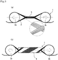
- Figs. 1 , 2 , and 3 illustrate an overall perspective view of a mode scrambler used in this embodiment, an explanatory side vi ew of the mode scrambler, and a side view of another embodiment of the mode scrambler, respectively.
- a supporting structure of a bobbin and a fiber is not illustrated in the drawings.
- a mode scrambler 1 is provided with two bobbins 3a and 3b arranged in parallel in a radial direction, and is configured such that it is possible to wind the fiber 2 around these bobbins 3a and 3b. As illustrated in Fig. 1 , for example, the single fiber 2 is wound around the bobbins 3a and 3b.
- the bobbins 3a and 3b are configured such that it is possible to rotate the bobbins 3a and 3b coaxially in opposing directions opposite to each other, for example, the bobbin 3a in an R1 direction and the bobbin 3b in an R2 direction, using an axis R as a rotation axis thereof, in a state where the fiber 2 is wound therearound. Further, when the bobbins 3a and 3b are rotated in the opposing directions opposite to each other in this manner, the fiber 2, wound around these bobbins 3a and 3b, is twisted so that a twisted portion 5, twisted while a plurality of fibers is entangled with each other, is formed in the fiber 2.
- the twisted portion 5 is formed between the bobbins 3a and 3b so that the plurality of fibers 2 is twisted while being entangled with each other.
- the twisted portion 5 is oriented in a direction having a predetermined angle with respect to a longitudinal direction in which the fiber 2 is disposed, and is formed such that the fiber 2 is spirally wound around with respect to the other fiber 2. Since the twisted portion 5 is formed as the fiber 2 is twisted as described above, a higher-order mode distribution transmitted through the fiber 2 is attenuated at the twisted portion 5, and it is possible to obtain output light with a stable steady mode distribution.
- the fiber 2 used in the present embodiment is an SI multimode fiber having a core diameter exceeding several tens ⁇ m and a numerical aperture of 0.2 or more, and is incorporated in the mode scrambler 1 after being cut to have a length of 10m or less.
- the straight arrows in Fig. 1 indicate transmission paths of light in the fiber.
- a fiber other than this such as a GI fiber, may be used as the fiber to be used, and is not limited to the above-described example.
- the mode scrambler 1 can change the mode distribution to be output depending on the number of rotations of the bobbins 3a and 3b by using such a structure. That is, as understood from Fig. 1 , torsional stresses in opposite directions to each other act on the fiber 2 in both propagation directions of travel c, which is a direction in which the incident light is incident on the twisted portion 5 for the first time, and return d, which is a direction in which in which light is incident from an opposing direction to the travel c toward the twisted portion 5, that is, the light having passed through the twisted portion 5 at least once is incident to the twisted portion 5 again, in the mode scrambler 1 according to the present embodiment.
- the mode scrambler 1 of the present embodiment can generate dispersion of the mode distribution in the twisted portion 5 which is the twisted part without reducing a bending radius of the fiber 2. Further, since the light does not leak to the outside regarding the light transmission in the fiber, it is possible to perform the transmission in the state of suppressing the loss caused by the light leaking out of the fiber.
- the single fiber 2 is wound around the bobbins 3a and 3b, and the two bobbins 3a and 3b around which this fiber 2 has been wound are set to the state of being mutually rotated in the opposing directions opposite to each other, thereby generating the dispersion of the mode distribution in the fiber in the mode scrambler 1 of the present embodiment as understood from Fig. 2 .
- the simplified structure obtained only by winding the fiber 2 around the bobbins 3a and 3b and causing twist in the fiber 2 to form the twisted portion 5, is provided in the operation and configuration of the mode scrambler 1 of the present embodiment, thereby enabling the mode output, that is, the output of the steady mode distribution.
- the mode scrambler 1 as a whole can have an inexpensive configuration while improving practicality.
- a fiber having a hard fiber cover and having a small maximum diameter represented by an outdoor fiber
- the multimode fiber having the core diameter exceeding several tens ⁇ m and the numerical aperture of 0.2 or more it is possible to reproduce a mode distribution equivalent to the steady mode distribution when light is propagated over a long distance of the fiber 2 by making the numerical aperture of the incident light smaller than the numerical aperture of the fiber 2 even when the incident light is smaller than the numerical aperture of the fiber to be measured through the suppression of the loss caused by the light leaking out of the fiber in the invention described in the present application. Further, it is possible to perform output in not only the steady mode distribution but also the entire mode distribution including a higher-order mode distribution by using an adjustment mechanism based on the number of turns and the number of rotations.
- the mode scrambler 1 according to the present invention when used, it is possible to provide the mode scrambler 1 in which the steady mode distribution can be obtained in a short distance, and switch to the entire mode distribution is easy.
- the mode scrambler according to the present invention only one example of the mode scrambler according to the present invention has been described as above, and the configuration may be changed as appropriate without departing from the scope of the claims.
Landscapes
- Physics & Mathematics (AREA)
- General Physics & Mathematics (AREA)
- Optics & Photonics (AREA)
- Electromagnetism (AREA)
- Engineering & Computer Science (AREA)
- Computer Networks & Wireless Communication (AREA)
- Signal Processing (AREA)
- Light Guides In General And Applications Therefor (AREA)
- Optical Communication System (AREA)
- Optical Fibers, Optical Fiber Cores, And Optical Fiber Bundles (AREA)
Description
- The present invention relates to a mode scrambler capable of arbitrarily changing a mode distribution between an incident light side and an outgoing light side of a mounted fiber.
- Currently, mode scramblers for stabilizing outgoing light from a light source has been used in an insertion loss test of an optical fiber and an optical measuring instrument. Among these mode scramblers, there is a mode scrambler having a structure using a graded index (GI) fiber, described in Japanese Utility Model Application Laid-Open No.
61-013803 2005-099274 -
- Patent Literature 1: Japanese Utility Model Application Laid-Open No.
61-013803 - Patent Literature 2: Japanese Patent Application Laid-Open No.
2005-099274 -
-
US 2006/222305A1 discloses an apparatus for remote laser delivery systems. A helical fiber optic mode scrambler is disclosed having an integral portion of a fiber optic cable having a rigid curvature predetermined to influence the intermodal dispersion characteristics of the fiber optic cable. The scrambler includes a support structure and a cylindrical sleeve that work in tandem to maintain the predetermined spiral curvature of the helical mode scrambler. - While having the above-described effect, the mode scramblers described in the prior art use a structure that allows the higher-order mode distribution to leak out of the fiber, which is difficult to reproduce a steady mode distribution equivalent to that in the case of long distance propagation at the time of being used in a step index (SI) multimode fiber. More specifically, dispersion of the mode distribution is caused by a stress acting on the fiber, but the steady mode distribution equivalent to that obtained when propagated over a long distance is not reproduced. Further, a loss caused by light leaking out of the fiber is large. Further, in a shape of being continuously wound in the same direction as described in
Patent Literature 2, the mode distribution varies depending on a wound diameter and a mode distribution of incident light, and it is difficult to output a stable steady mode distribution. - In regard to the above-described problems, an object of the invention described in the present application is to provide a mode scrambler that is capable of stably performing output of a steady mode distribution in a state where attenuation is suppressed in a short distance and arbitrarily changing the mode distribution in a multimode fiber.
- For the above-described object, the invention describes a mode scrambler according to claim 1. An additional embodiment is set out in
dependent claim 2. - According to the above technical characteristics, the invention described in the present application make it possible to obtain a steady mode distribution while suppressing attenuation of an SI multimode fiber to be used. This is because dispersion of the mode distribution occurs in the twisted portion of the fiber. That is, the mode scrambler of the present application has a structure in which a bending radius of the fiber is not reduced. Thus, when light is transmitted in the fiber, light does not leak to the outside, and the transmission can be performed in the state of suppressing a loss caused by the light leaking out of the fiber. Further, the dispersion of the mode distribution in the twisted portion is generated by mutually rotating the plurality of bobbins around which the single fiber is wound in the invention described in the present application. Thus, it is possible to output a steady mode distribution corresponding to characteristics of each SI fiber by changing the number of rotations of the bobbin. Here, the number of rotations also covers the number of rotations including decimal places, for example, 1.3 rotation or the like. Furthermore, the mode scrambler of the present application has a simplified basic structure of being merely wound around the bobbin and twisted in terms of its operation and configuration. Thus, it is possible to obtain a desired mode distribution at low cost at the time of using the SI multimode fiber by using the mode scrambler described in the present application. Incidentally, it is possible to obtain a similar effect to that of the case of changing the number of rotations even by changing the number of turns from the same technical viewpoint as the number of rotations.
- Further, through suppression of the loss caused by the light leaking out of the fiber, it is possible to reproduce a mode distribution equivalent to the steady mode distribution when light is propagated over a long distance of the fiber in the invention described in the present application by making a numerical aperture of the incident light smaller than a numerical aperture of the SI multimode fiber used in the invention described in the present application. Further, through suppression of the loss caused by the light leaking out of the fiber, it is possible to output the steady mode distribution in a short distance even when the light incident to the fiber is smaller than the numerical aperture of the fiber. Further, it is possible to perform output in not only the steady mode distribution but also the entire mode distribution including a higher-order mode distribution by using an adjustment mechanism based on the number of turns and the number of rotations.
- In addition to the effects according to the basic structure of the present application described above, it is possible to improve the versatility of the mode scrambler by using the invention described in the second aspect of the present application. That is, even for a fiber having a hard fiber cover and having a small maximum diameter, represented by an outdoor fiber, it is possible to impart the above-described effects by twisting the fiber in a state where a torsional diameter is enlarged using the core post described in the second aspect.
- As described above, when the invention described in the present application is used, it is possible to provide the mode scrambler in which the steady mode distribution can be obtained in a short distance, and switch to the entire mode distribution is easy.
-
-
Fig. 1 is an overall perspective view of a mode scrambler used in the most preferable embodiment of the present invention. -
Fig. 2 is an explanatory side view of the mode scrambler illustrated inFig. 1 . -
Fig. 3 is a side view according to another embodiment of the mode scrambler illustrated inFig. 1 . - Hereinafter, embodiments of a mode scrambler according to the present invention will be described with reference to
Figs. 1 ,2 and3 . Incidentally, common reference numerals are given to those functioning as the same parts with respect to reference numerals illustrated in the drawings. -
Figs. 1 ,2 , and3 illustrate an overall perspective view of a mode scrambler used in this embodiment, an explanatory side vi ew of the mode scrambler, and a side view of another embodiment of the mode scrambler, respectively. Incidentally, a supporting structure of a bobbin and a fiber is not illustrated in the drawings. - As understood from
Figs. 1 and2 , a mode scrambler 1 according to the present embodiment is provided with twobobbins fiber 2 around thesebobbins Fig. 1 , for example, thesingle fiber 2 is wound around thebobbins bobbins bobbins bobbin 3a in an R1 direction and thebobbin 3b in an R2 direction, using an axis R as a rotation axis thereof, in a state where thefiber 2 is wound therearound. Further, when thebobbins fiber 2, wound around thesebobbins twisted portion 5, twisted while a plurality of fibers is entangled with each other, is formed in thefiber 2. - The
twisted portion 5 is formed between thebobbins fibers 2 is twisted while being entangled with each other. Thetwisted portion 5 is oriented in a direction having a predetermined angle with respect to a longitudinal direction in which thefiber 2 is disposed, and is formed such that thefiber 2 is spirally wound around with respect to theother fiber 2. Since thetwisted portion 5 is formed as thefiber 2 is twisted as described above, a higher-order mode distribution transmitted through thefiber 2 is attenuated at thetwisted portion 5, and it is possible to obtain output light with a stable steady mode distribution. - Incidentally, the
fiber 2 used in the present embodiment is an SI multimode fiber having a core diameter exceeding several tens µm and a numerical aperture of 0.2 or more, and is incorporated in the mode scrambler 1 after being cut to have a length of 10m or less. Further, the straight arrows inFig. 1 indicate transmission paths of light in the fiber. Although the description is given using the example using SI multimode fiber in the present embodiment, a fiber other than this, such as a GI fiber, may be used as the fiber to be used, and is not limited to the above-described example. - Further, the mode scrambler 1 can change the mode distribution to be output depending on the number of rotations of the
bobbins Fig. 1 , torsional stresses in opposite directions to each other act on thefiber 2 in both propagation directions of travel c, which is a direction in which the incident light is incident on thetwisted portion 5 for the first time, and return d, which is a direction in which in which light is incident from an opposing direction to the travel c toward thetwisted portion 5, that is, the light having passed through thetwisted portion 5 at least once is incident to thetwisted portion 5 again, in the mode scrambler 1 according to the present embodiment. Accordingly, the mode scrambler 1 of the present embodiment can generate dispersion of the mode distribution in thetwisted portion 5 which is the twisted part without reducing a bending radius of thefiber 2. Further, since the light does not leak to the outside regarding the light transmission in the fiber, it is possible to perform the transmission in the state of suppressing the loss caused by the light leaking out of the fiber. - Further, the
single fiber 2 is wound around thebobbins bobbins fiber 2 has been wound are set to the state of being mutually rotated in the opposing directions opposite to each other, thereby generating the dispersion of the mode distribution in the fiber in the mode scrambler 1 of the present embodiment as understood fromFig. 2 . Thus, it is possible to output the steady mode distribution corresponding to the characteristics of thefiber 2 by changing the number of rotations of thebobbins fiber 2 around thebobbins fiber 2 to form thetwisted portion 5, is provided in the operation and configuration of the mode scrambler 1 of the present embodiment, thereby enabling the mode output, that is, the output of the steady mode distribution. Thus, the mode scrambler 1 as a whole can have an inexpensive configuration while improving practicality. - Incidentally, from the same technical viewpoint as the number of times of twist as the number of times of twisting the
fiber 2 in thetwisted portion 5, even when it is configured such that the number of turns as the number of times of winding thefiber 2 around the twobobbins Fig. 3(a) . Further, the stress acting on thefiber 2 increases depending on a rotation angle of thebobbins Figs. 1 and2 together with high general versatility by adopting the twisted structure using thecore post 4 as illustrated inFig. 3(b) . - In addition to these effects, for example, in the multimode fiber having the core diameter exceeding several tens µm and the numerical aperture of 0.2 or more, it is possible to reproduce a mode distribution equivalent to the steady mode distribution when light is propagated over a long distance of the
fiber 2 by making the numerical aperture of the incident light smaller than the numerical aperture of thefiber 2 even when the incident light is smaller than the numerical aperture of the fiber to be measured through the suppression of the loss caused by the light leaking out of the fiber in the invention described in the present application. Further, it is possible to perform output in not only the steady mode distribution but also the entire mode distribution including a higher-order mode distribution by using an adjustment mechanism based on the number of turns and the number of rotations. - As described above, when the mode scrambler 1 according to the present invention is used, it is possible to provide the mode scrambler 1 in which the steady mode distribution can be obtained in a short distance, and switch to the entire mode distribution is easy. Incidentally, only one example of the mode scrambler according to the present invention has been described as above, and the configuration may be changed as appropriate without departing from the scope of the claims.
-
- 1
- mode scrambler
- 2
- fiber
- 3a, 3b
- bobbin
- 4
- core post
- 5
- twisted portion
- c, d
- light propagation direction in fiber
- R
- axis
Claims (2)
- A mode scrambler (1) comprising:a plurality of bobbins (3a, 3b), arranged in a radial direction and bundled together at intervals; anda multimode optical fiber (2) wound around the bobbins (3a, 3b) wherein the bobbins (3a, 3b) are rotated about an arranged direction thereof as an axis (R) to form a twisted portion (5) between the bobbins, and the twisted portion (5) formed by the rotation of the bobbins (3a, 3b) comprises twisted portions of the multimode optical fiber (2) that form the twisted portion (5) and are twisted while being entangled with each other.
- The mode scrambler (1) according to claim 1, wherein the multimode optical fiber (2) is wound around a core post (4) provided between the bobbins (3a, 3b) at the time of rotating the bobbins (3a, 3b) and the twisted portion (5) is formed at a fiber winding portion of the core post (4).
Applications Claiming Priority (2)
| Application Number | Priority Date | Filing Date | Title |
|---|---|---|---|
| JP2015143172 | 2015-07-17 | ||
| PCT/JP2016/071031 WO2017014195A1 (en) | 2015-07-17 | 2016-07-15 | Mode scrambler |
Publications (3)
| Publication Number | Publication Date |
|---|---|
| EP3327473A1 EP3327473A1 (en) | 2018-05-30 |
| EP3327473A4 EP3327473A4 (en) | 2019-03-13 |
| EP3327473B1 true EP3327473B1 (en) | 2021-06-16 |
Family
ID=57834441
Family Applications (1)
| Application Number | Title | Priority Date | Filing Date |
|---|---|---|---|
| EP16827755.6A Active EP3327473B1 (en) | 2015-07-17 | 2016-07-15 | Mode scrambler |
Country Status (6)
| Country | Link |
|---|---|
| US (1) | US10254482B2 (en) |
| EP (1) | EP3327473B1 (en) |
| JP (1) | JP6871622B2 (en) |
| KR (1) | KR102706540B1 (en) |
| CN (1) | CN107533191B (en) |
| WO (1) | WO2017014195A1 (en) |
Families Citing this family (1)
| Publication number | Priority date | Publication date | Assignee | Title |
|---|---|---|---|---|
| CN111771146A (en) * | 2018-02-27 | 2020-10-13 | 安达满纳米奇精密宝石有限公司 | mode controller |
Family Cites Families (21)
| Publication number | Priority date | Publication date | Assignee | Title |
|---|---|---|---|---|
| JPS53129664A (en) * | 1977-04-18 | 1978-11-11 | Nippon Telegr & Teleph Corp <Ntt> | Optical fiber cable |
| JPS5660908U (en) * | 1979-10-18 | 1981-05-23 | ||
| JPS6113803U (en) | 1984-06-28 | 1986-01-27 | 日立電線株式会社 | mode scrambler |
| US4923268A (en) * | 1987-09-14 | 1990-05-08 | Aster Corporation | Fiber optic coupler |
| US4877305A (en) * | 1988-03-09 | 1989-10-31 | Ricciardelli Robert H | Fiber optic light mode mixer |
| US4932748A (en) * | 1988-03-09 | 1990-06-12 | Ricciardelli Robert H | Fiber optic light mode mixer |
| US4934787A (en) * | 1988-08-02 | 1990-06-19 | Mitsubishi Rayon Co., Ltd. | Mode scrambler |
| JPH0242407A (en) * | 1988-08-02 | 1990-02-13 | Mitsubishi Rayon Co Ltd | mode scrambler |
| JPH03144337A (en) * | 1989-10-31 | 1991-06-19 | Showa Electric Wire & Cable Co Ltd | Measuring method for characteristic of optical fiber |
| KR100282775B1 (en) * | 1998-02-21 | 2001-03-02 | 서원석 | Optical fiber polarization scrambler and its driving parameter input method |
| DE19841068A1 (en) * | 1998-09-09 | 2000-03-16 | Deutsche Telekom Ag | Optical link |
| JP3959871B2 (en) * | 1998-10-28 | 2007-08-15 | 住友電装株式会社 | Optical star coupler |
| US6625363B2 (en) * | 2001-06-06 | 2003-09-23 | Nufern | Cladding-pumped optical fiber |
| JP2005099274A (en) | 2003-09-24 | 2005-04-14 | Hitachi Chem Co Ltd | Mode scrambler using optical fiber wiring board |
| US7787728B2 (en) * | 2004-03-31 | 2010-08-31 | Zolo Technologies, Inc. | Optical mode noise averaging device |
| US7590317B2 (en) * | 2005-03-31 | 2009-09-15 | John Crownover | High energy fiber optics laser delivery system with improved scrambling capabilities |
| US7269324B2 (en) * | 2005-03-31 | 2007-09-11 | Crownover John D | Helical fiber optic mode scrambler |
| JP2007187774A (en) * | 2006-01-12 | 2007-07-26 | Shinka Jitsugyo Kk | Manufacturing method of multimode optical module |
| US8373852B2 (en) * | 2007-11-26 | 2013-02-12 | Exfo Inc. | Optical waveguide rotator mechanism, birefringence-inducing element and polarization control devices employing either or both and methods of using same |
| JP5718153B2 (en) | 2011-05-26 | 2015-05-13 | 株式会社トプコン | Plant sensor device |
| JP2015175958A (en) * | 2014-03-14 | 2015-10-05 | 浜松ホトニクス株式会社 | Semiconductor laser module, semiconductor laser light source, and semiconductor laser system |
-
2016
- 2016-07-15 CN CN201680026753.7A patent/CN107533191B/en active Active
- 2016-07-15 US US15/577,621 patent/US10254482B2/en active Active
- 2016-07-15 EP EP16827755.6A patent/EP3327473B1/en active Active
- 2016-07-15 KR KR1020177034672A patent/KR102706540B1/en active Active
- 2016-07-15 WO PCT/JP2016/071031 patent/WO2017014195A1/en not_active Ceased
- 2016-07-15 JP JP2017529885A patent/JP6871622B2/en active Active
Non-Patent Citations (1)
| Title |
|---|
| None * |
Also Published As
| Publication number | Publication date |
|---|---|
| EP3327473A4 (en) | 2019-03-13 |
| WO2017014195A1 (en) | 2017-01-26 |
| CN107533191A (en) | 2018-01-02 |
| EP3327473A1 (en) | 2018-05-30 |
| CN107533191B (en) | 2020-02-28 |
| JPWO2017014195A1 (en) | 2018-06-28 |
| US10254482B2 (en) | 2019-04-09 |
| US20180164503A1 (en) | 2018-06-14 |
| KR102706540B1 (en) | 2024-09-12 |
| KR20180056414A (en) | 2018-05-28 |
| JP6871622B2 (en) | 2021-05-12 |
Similar Documents
| Publication | Publication Date | Title |
|---|---|---|
| JP6372598B2 (en) | Multi-core optical fiber, multi-core optical fiber cable, and multi-core optical fiber transmission system | |
| JP5768090B2 (en) | Fan-in / fan-out device for multi-core fiber | |
| US8380029B2 (en) | Fiber optic cable furcation methods and assemblies | |
| JP2018084813A5 (en) | ||
| JP2013182157A (en) | Optical fiber ribbon and optical fiber cable housing optical fiber ribbon therein | |
| WO2006051898A1 (en) | Optical cable | |
| WO2013099555A1 (en) | Multicore optical fiber | |
| JP2012203035A (en) | Multi-core fiber and method of manufacturing the same | |
| JP2011169938A (en) | Unit type optical fiber ribbon and optical fiber cable | |
| CN112334809A (en) | Optical fiber cable | |
| US11340397B2 (en) | Mode controller | |
| US10254482B2 (en) | Mode scrambler | |
| Horiguchi et al. | Low-attenuation variable mode control using twist processing for step-index optical fiber loops | |
| AU2010213493B2 (en) | Duplex cables and zipcord cables and breakout cables incorporating duplex cables | |
| JPH0242407A (en) | mode scrambler | |
| JP7613595B2 (en) | Fiber optic cable | |
| CN214540116U (en) | A decoherent fiber | |
| Sakata et al. | In-fibre LP11–LP21 mode conversion using force-induced long-period fibre gratings with polarization controllers | |
| JPWO2020080385A1 (en) | Fiber optic cable | |
| JP2023114328A (en) | Optical fiber cable | |
| WO2026054847A1 (en) | Optical fiber cable comprising a hollow core fiber | |
| CN103558672A (en) | Three-unit unidirectional spiral stranded layer stranded optical cable | |
| JPS5814103A (en) | Assembling device for optical fiber | |
| TH107963A (en) | Fiber optic cable And the method for constructing it is the same thing. | |
| EA201200159A1 (en) | OPTICAL CABLE (OPTIONS) |
Legal Events
| Date | Code | Title | Description |
|---|---|---|---|
| STAA | Information on the status of an ep patent application or granted ep patent |
Free format text: STATUS: THE INTERNATIONAL PUBLICATION HAS BEEN MADE |
|
| PUAI | Public reference made under article 153(3) epc to a published international application that has entered the european phase |
Free format text: ORIGINAL CODE: 0009012 |
|
| STAA | Information on the status of an ep patent application or granted ep patent |
Free format text: STATUS: REQUEST FOR EXAMINATION WAS MADE |
|
| 17P | Request for examination filed |
Effective date: 20180122 |
|
| AK | Designated contracting states |
Kind code of ref document: A1 Designated state(s): AL AT BE BG CH CY CZ DE DK EE ES FI FR GB GR HR HU IE IS IT LI LT LU LV MC MK MT NL NO PL PT RO RS SE SI SK SM TR |
|
| AX | Request for extension of the european patent |
Extension state: BA ME |
|
| DAV | Request for validation of the european patent (deleted) | ||
| DAX | Request for extension of the european patent (deleted) | ||
| A4 | Supplementary search report drawn up and despatched |
Effective date: 20190212 |
|
| RIC1 | Information provided on ipc code assigned before grant |
Ipc: G02B 6/27 20060101ALI20190206BHEP Ipc: G02B 6/46 20060101ALI20190206BHEP Ipc: G02B 6/14 20060101ALI20190206BHEP Ipc: H04B 10/2581 20130101ALI20190206BHEP Ipc: G02B 6/00 20060101AFI20190206BHEP Ipc: G02B 6/44 20060101ALN20190206BHEP |
|
| RIC1 | Information provided on ipc code assigned before grant |
Ipc: G02B 6/14 20060101ALI20201202BHEP Ipc: G02B 6/44 20060101ALN20201202BHEP Ipc: G02B 6/27 20060101ALI20201202BHEP Ipc: G02B 6/46 20060101ALI20201202BHEP Ipc: H04B 10/2581 20130101ALI20201202BHEP Ipc: G02B 6/00 20060101AFI20201202BHEP |
|
| GRAP | Despatch of communication of intention to grant a patent |
Free format text: ORIGINAL CODE: EPIDOSNIGR1 |
|
| RIC1 | Information provided on ipc code assigned before grant |
Ipc: G02B 6/00 20060101AFI20201211BHEP Ipc: G02B 6/14 20060101ALI20201211BHEP Ipc: G02B 6/46 20060101ALI20201211BHEP Ipc: G02B 6/44 20060101ALN20201211BHEP Ipc: H04B 10/2581 20130101ALI20201211BHEP Ipc: G02B 6/27 20060101ALI20201211BHEP |
|
| STAA | Information on the status of an ep patent application or granted ep patent |
Free format text: STATUS: GRANT OF PATENT IS INTENDED |
|
| RIC1 | Information provided on ipc code assigned before grant |
Ipc: G02B 6/14 20060101ALI20201221BHEP Ipc: G02B 6/00 20060101AFI20201221BHEP Ipc: H04B 10/2581 20130101ALI20201221BHEP Ipc: G02B 6/46 20060101ALI20201221BHEP Ipc: G02B 6/27 20060101ALI20201221BHEP Ipc: G02B 6/44 20060101ALN20201221BHEP |
|
| INTG | Intention to grant announced |
Effective date: 20210121 |
|
| GRAS | Grant fee paid |
Free format text: ORIGINAL CODE: EPIDOSNIGR3 |
|
| GRAA | (expected) grant |
Free format text: ORIGINAL CODE: 0009210 |
|
| STAA | Information on the status of an ep patent application or granted ep patent |
Free format text: STATUS: THE PATENT HAS BEEN GRANTED |
|
| AK | Designated contracting states |
Kind code of ref document: B1 Designated state(s): AL AT BE BG CH CY CZ DE DK EE ES FI FR GB GR HR HU IE IS IT LI LT LU LV MC MK MT NL NO PL PT RO RS SE SI SK SM TR |
|
| REG | Reference to a national code |
Ref country code: GB Ref legal event code: FG4D |
|
| REG | Reference to a national code |
Ref country code: CH Ref legal event code: EP |
|
| REG | Reference to a national code |
Ref country code: DE Ref legal event code: R096 Ref document number: 602016059468 Country of ref document: DE |
|
| REG | Reference to a national code |
Ref country code: AT Ref legal event code: REF Ref document number: 1402809 Country of ref document: AT Kind code of ref document: T Effective date: 20210715 |
|
| REG | Reference to a national code |
Ref country code: IE Ref legal event code: FG4D |
|
| REG | Reference to a national code |
Ref country code: LT Ref legal event code: MG9D |
|
| PG25 | Lapsed in a contracting state [announced via postgrant information from national office to epo] |
Ref country code: LT Free format text: LAPSE BECAUSE OF FAILURE TO SUBMIT A TRANSLATION OF THE DESCRIPTION OR TO PAY THE FEE WITHIN THE PRESCRIBED TIME-LIMIT Effective date: 20210616 Ref country code: FI Free format text: LAPSE BECAUSE OF FAILURE TO SUBMIT A TRANSLATION OF THE DESCRIPTION OR TO PAY THE FEE WITHIN THE PRESCRIBED TIME-LIMIT Effective date: 20210616 Ref country code: HR Free format text: LAPSE BECAUSE OF FAILURE TO SUBMIT A TRANSLATION OF THE DESCRIPTION OR TO PAY THE FEE WITHIN THE PRESCRIBED TIME-LIMIT Effective date: 20210616 Ref country code: BG Free format text: LAPSE BECAUSE OF FAILURE TO SUBMIT A TRANSLATION OF THE DESCRIPTION OR TO PAY THE FEE WITHIN THE PRESCRIBED TIME-LIMIT Effective date: 20210916 |
|
| REG | Reference to a national code |
Ref country code: AT Ref legal event code: MK05 Ref document number: 1402809 Country of ref document: AT Kind code of ref document: T Effective date: 20210616 |
|
| REG | Reference to a national code |
Ref country code: NL Ref legal event code: MP Effective date: 20210616 |
|
| PG25 | Lapsed in a contracting state [announced via postgrant information from national office to epo] |
Ref country code: NO Free format text: LAPSE BECAUSE OF FAILURE TO SUBMIT A TRANSLATION OF THE DESCRIPTION OR TO PAY THE FEE WITHIN THE PRESCRIBED TIME-LIMIT Effective date: 20210916 Ref country code: SE Free format text: LAPSE BECAUSE OF FAILURE TO SUBMIT A TRANSLATION OF THE DESCRIPTION OR TO PAY THE FEE WITHIN THE PRESCRIBED TIME-LIMIT Effective date: 20210616 Ref country code: RS Free format text: LAPSE BECAUSE OF FAILURE TO SUBMIT A TRANSLATION OF THE DESCRIPTION OR TO PAY THE FEE WITHIN THE PRESCRIBED TIME-LIMIT Effective date: 20210616 Ref country code: GR Free format text: LAPSE BECAUSE OF FAILURE TO SUBMIT A TRANSLATION OF THE DESCRIPTION OR TO PAY THE FEE WITHIN THE PRESCRIBED TIME-LIMIT Effective date: 20210917 Ref country code: LV Free format text: LAPSE BECAUSE OF FAILURE TO SUBMIT A TRANSLATION OF THE DESCRIPTION OR TO PAY THE FEE WITHIN THE PRESCRIBED TIME-LIMIT Effective date: 20210616 |
|
| PG25 | Lapsed in a contracting state [announced via postgrant information from national office to epo] |
Ref country code: SK Free format text: LAPSE BECAUSE OF FAILURE TO SUBMIT A TRANSLATION OF THE DESCRIPTION OR TO PAY THE FEE WITHIN THE PRESCRIBED TIME-LIMIT Effective date: 20210616 Ref country code: SM Free format text: LAPSE BECAUSE OF FAILURE TO SUBMIT A TRANSLATION OF THE DESCRIPTION OR TO PAY THE FEE WITHIN THE PRESCRIBED TIME-LIMIT Effective date: 20210616 Ref country code: CZ Free format text: LAPSE BECAUSE OF FAILURE TO SUBMIT A TRANSLATION OF THE DESCRIPTION OR TO PAY THE FEE WITHIN THE PRESCRIBED TIME-LIMIT Effective date: 20210616 Ref country code: EE Free format text: LAPSE BECAUSE OF FAILURE TO SUBMIT A TRANSLATION OF THE DESCRIPTION OR TO PAY THE FEE WITHIN THE PRESCRIBED TIME-LIMIT Effective date: 20210616 Ref country code: AT Free format text: LAPSE BECAUSE OF FAILURE TO SUBMIT A TRANSLATION OF THE DESCRIPTION OR TO PAY THE FEE WITHIN THE PRESCRIBED TIME-LIMIT Effective date: 20210616 Ref country code: NL Free format text: LAPSE BECAUSE OF FAILURE TO SUBMIT A TRANSLATION OF THE DESCRIPTION OR TO PAY THE FEE WITHIN THE PRESCRIBED TIME-LIMIT Effective date: 20210616 Ref country code: RO Free format text: LAPSE BECAUSE OF FAILURE TO SUBMIT A TRANSLATION OF THE DESCRIPTION OR TO PAY THE FEE WITHIN THE PRESCRIBED TIME-LIMIT Effective date: 20210616 Ref country code: PT Free format text: LAPSE BECAUSE OF FAILURE TO SUBMIT A TRANSLATION OF THE DESCRIPTION OR TO PAY THE FEE WITHIN THE PRESCRIBED TIME-LIMIT Effective date: 20211018 Ref country code: ES Free format text: LAPSE BECAUSE OF FAILURE TO SUBMIT A TRANSLATION OF THE DESCRIPTION OR TO PAY THE FEE WITHIN THE PRESCRIBED TIME-LIMIT Effective date: 20210616 |
|
| REG | Reference to a national code |
Ref country code: DE Ref legal event code: R119 Ref document number: 602016059468 Country of ref document: DE |
|
| PG25 | Lapsed in a contracting state [announced via postgrant information from national office to epo] |
Ref country code: PL Free format text: LAPSE BECAUSE OF FAILURE TO SUBMIT A TRANSLATION OF THE DESCRIPTION OR TO PAY THE FEE WITHIN THE PRESCRIBED TIME-LIMIT Effective date: 20210616 |
|
| REG | Reference to a national code |
Ref country code: CH Ref legal event code: PL |
|
| PG25 | Lapsed in a contracting state [announced via postgrant information from national office to epo] |
Ref country code: MC Free format text: LAPSE BECAUSE OF FAILURE TO SUBMIT A TRANSLATION OF THE DESCRIPTION OR TO PAY THE FEE WITHIN THE PRESCRIBED TIME-LIMIT Effective date: 20210616 |
|
| REG | Reference to a national code |
Ref country code: BE Ref legal event code: MM Effective date: 20210731 |
|
| PLBE | No opposition filed within time limit |
Free format text: ORIGINAL CODE: 0009261 |
|
| STAA | Information on the status of an ep patent application or granted ep patent |
Free format text: STATUS: NO OPPOSITION FILED WITHIN TIME LIMIT |
|
| PG25 | Lapsed in a contracting state [announced via postgrant information from national office to epo] |
Ref country code: LI Free format text: LAPSE BECAUSE OF NON-PAYMENT OF DUE FEES Effective date: 20210731 Ref country code: DK Free format text: LAPSE BECAUSE OF FAILURE TO SUBMIT A TRANSLATION OF THE DESCRIPTION OR TO PAY THE FEE WITHIN THE PRESCRIBED TIME-LIMIT Effective date: 20210616 Ref country code: DE Free format text: LAPSE BECAUSE OF NON-PAYMENT OF DUE FEES Effective date: 20220201 Ref country code: CH Free format text: LAPSE BECAUSE OF NON-PAYMENT OF DUE FEES Effective date: 20210731 |
|
| 26N | No opposition filed |
Effective date: 20220317 |
|
| PG25 | Lapsed in a contracting state [announced via postgrant information from national office to epo] |
Ref country code: LU Free format text: LAPSE BECAUSE OF NON-PAYMENT OF DUE FEES Effective date: 20210715 Ref country code: AL Free format text: LAPSE BECAUSE OF FAILURE TO SUBMIT A TRANSLATION OF THE DESCRIPTION OR TO PAY THE FEE WITHIN THE PRESCRIBED TIME-LIMIT Effective date: 20210616 |
|
| PG25 | Lapsed in a contracting state [announced via postgrant information from national office to epo] |
Ref country code: IT Free format text: LAPSE BECAUSE OF FAILURE TO SUBMIT A TRANSLATION OF THE DESCRIPTION OR TO PAY THE FEE WITHIN THE PRESCRIBED TIME-LIMIT Effective date: 20210616 Ref country code: FR Free format text: LAPSE BECAUSE OF NON-PAYMENT OF DUE FEES Effective date: 20210816 Ref country code: BE Free format text: LAPSE BECAUSE OF NON-PAYMENT OF DUE FEES Effective date: 20210731 Ref country code: IE Free format text: LAPSE BECAUSE OF NON-PAYMENT OF DUE FEES Effective date: 20210715 |
|
| PG25 | Lapsed in a contracting state [announced via postgrant information from national office to epo] |
Ref country code: HU Free format text: LAPSE BECAUSE OF FAILURE TO SUBMIT A TRANSLATION OF THE DESCRIPTION OR TO PAY THE FEE WITHIN THE PRESCRIBED TIME-LIMIT; INVALID AB INITIO Effective date: 20160715 |
|
| PG25 | Lapsed in a contracting state [announced via postgrant information from national office to epo] |
Ref country code: CY Free format text: LAPSE BECAUSE OF FAILURE TO SUBMIT A TRANSLATION OF THE DESCRIPTION OR TO PAY THE FEE WITHIN THE PRESCRIBED TIME-LIMIT Effective date: 20210616 |
|
| PG25 | Lapsed in a contracting state [announced via postgrant information from national office to epo] |
Ref country code: MK Free format text: LAPSE BECAUSE OF FAILURE TO SUBMIT A TRANSLATION OF THE DESCRIPTION OR TO PAY THE FEE WITHIN THE PRESCRIBED TIME-LIMIT Effective date: 20210616 |
|
| PG25 | Lapsed in a contracting state [announced via postgrant information from national office to epo] |
Ref country code: MT Free format text: LAPSE BECAUSE OF FAILURE TO SUBMIT A TRANSLATION OF THE DESCRIPTION OR TO PAY THE FEE WITHIN THE PRESCRIBED TIME-LIMIT Effective date: 20210616 |
|
| PGFP | Annual fee paid to national office [announced via postgrant information from national office to epo] |
Ref country code: GB Payment date: 20250724 Year of fee payment: 10 |
|
| PG25 | Lapsed in a contracting state [announced via postgrant information from national office to epo] |
Ref country code: TR Free format text: LAPSE BECAUSE OF FAILURE TO SUBMIT A TRANSLATION OF THE DESCRIPTION OR TO PAY THE FEE WITHIN THE PRESCRIBED TIME-LIMIT Effective date: 20210616 |