EP3327362A1 - Outdoor unit of air conditioner - Google Patents
Outdoor unit of air conditioner Download PDFInfo
- Publication number
- EP3327362A1 EP3327362A1 EP16904839.4A EP16904839A EP3327362A1 EP 3327362 A1 EP3327362 A1 EP 3327362A1 EP 16904839 A EP16904839 A EP 16904839A EP 3327362 A1 EP3327362 A1 EP 3327362A1
- Authority
- EP
- European Patent Office
- Prior art keywords
- chamber
- air
- outdoor unit
- electric component
- ventilation
- Prior art date
- Legal status (The legal status is an assumption and is not a legal conclusion. Google has not performed a legal analysis and makes no representation as to the accuracy of the status listed.)
- Granted
Links
- 238000009423 ventilation Methods 0.000 claims abstract description 78
- 238000005192 partition Methods 0.000 claims abstract description 55
- 238000004378 air conditioning Methods 0.000 claims abstract description 30
- 238000001816 cooling Methods 0.000 claims abstract description 21
- 239000003507 refrigerant Substances 0.000 claims abstract description 11
- 238000000638 solvent extraction Methods 0.000 claims abstract description 4
- 230000000694 effects Effects 0.000 description 11
- 238000010586 diagram Methods 0.000 description 6
- XLYOFNOQVPJJNP-UHFFFAOYSA-N water Substances O XLYOFNOQVPJJNP-UHFFFAOYSA-N 0.000 description 6
- 230000005855 radiation Effects 0.000 description 4
- 230000015556 catabolic process Effects 0.000 description 3
- 238000006731 degradation reaction Methods 0.000 description 3
- 229910052751 metal Inorganic materials 0.000 description 3
- 239000002184 metal Substances 0.000 description 3
- 239000004065 semiconductor Substances 0.000 description 3
- RYGMFSIKBFXOCR-UHFFFAOYSA-N Copper Chemical compound [Cu] RYGMFSIKBFXOCR-UHFFFAOYSA-N 0.000 description 2
- 229910052782 aluminium Inorganic materials 0.000 description 2
- XAGFODPZIPBFFR-UHFFFAOYSA-N aluminium Chemical compound [Al] XAGFODPZIPBFFR-UHFFFAOYSA-N 0.000 description 2
- 229910052802 copper Inorganic materials 0.000 description 2
- 239000010949 copper Substances 0.000 description 2
- 238000007599 discharging Methods 0.000 description 2
- 230000005484 gravity Effects 0.000 description 2
- 238000007664 blowing Methods 0.000 description 1
- 230000007797 corrosion Effects 0.000 description 1
- 238000005260 corrosion Methods 0.000 description 1
- 230000002708 enhancing effect Effects 0.000 description 1
- 230000017525 heat dissipation Effects 0.000 description 1
- 230000020169 heat generation Effects 0.000 description 1
- 239000007788 liquid Substances 0.000 description 1
- 230000002265 prevention Effects 0.000 description 1
- 239000011347 resin Substances 0.000 description 1
- 229920005989 resin Polymers 0.000 description 1
Images


Classifications
-
- F—MECHANICAL ENGINEERING; LIGHTING; HEATING; WEAPONS; BLASTING
- F24—HEATING; RANGES; VENTILATING
- F24F—AIR-CONDITIONING; AIR-HUMIDIFICATION; VENTILATION; USE OF AIR CURRENTS FOR SCREENING
- F24F1/00—Room units for air-conditioning, e.g. separate or self-contained units or units receiving primary air from a central station
- F24F1/06—Separate outdoor units, e.g. outdoor unit to be linked to a separate room comprising a compressor and a heat exchanger
- F24F1/20—Electric components for separate outdoor units
- F24F1/24—Cooling of electric components
-
- F—MECHANICAL ENGINEERING; LIGHTING; HEATING; WEAPONS; BLASTING
- F24—HEATING; RANGES; VENTILATING
- F24F—AIR-CONDITIONING; AIR-HUMIDIFICATION; VENTILATION; USE OF AIR CURRENTS FOR SCREENING
- F24F1/00—Room units for air-conditioning, e.g. separate or self-contained units or units receiving primary air from a central station
- F24F1/06—Separate outdoor units, e.g. outdoor unit to be linked to a separate room comprising a compressor and a heat exchanger
- F24F1/46—Component arrangements in separate outdoor units
- F24F1/48—Component arrangements in separate outdoor units characterised by air airflow, e.g. inlet or outlet airflow
- F24F1/54—Inlet and outlet arranged on opposite sides
Definitions
- the present invention relates to an outdoor unit for an air-conditioning apparatus, the outdoor unit having a function of enhancing a cooling capacity of cooling electric components that generate heat.
- an outdoor unit for an air-conditioning apparatus typically, a configuration is known that the inside of a casing constituting the outline is partitioned by partition plates to include a plurality of chambers such as a machine chamber, an electric component chamber, and a ventilator chamber.
- a plurality of chambers such as a machine chamber, an electric component chamber, and a ventilator chamber.
- electric components such as an electric power board for driving a compressor disposed in the machine chamber, and a control board for controlling a refrigerant circuit configured with a compressor and other devices are accommodated.
- the electric components generate heat while the air-conditioning apparatus is being driven.
- the boards may be damaged by expansion caused by heat, characteristics of the semiconductors may change, or components on the boards may be degraded.
- various ventilation passages are designed to reduce the heat generation by the electric components.
- a ventilator chamber including propeller fans, and a machine chamber including an electric component box are partitioned by a partition plate.
- the machine chamber includes a compressor chamber including a compressor, and a ventilation passage chamber for allowing communication between the ventilator chamber and the outside.
- the compressor chamber and the ventilation passage chamber are partitioned by an electric component box having the top face on which a radiation fin is attached.
- an electric power board for driving the compressor for example, and a control board for controlling a refrigerant circuit are accommodated.
- Patent Literature 1 Japanese Unexamined Utility Model Application Publication No. H6-35835
- the present invention has been made to address the above-described issue, and has an object to provide an outdoor unit for an air-conditioning apparatus to reduce the temperature of the entire electric component chamber in which an electric power board and a control board are disposed, so that electric components are cooled in a sufficient manner, and a degradation of the electric components is prevented.
- the outdoor unit includes a plurality of accommodating chambers that are respectively adjacent to each other, and the plurality of accommodating chambers are formed by partitioning a casing including an air inlet and an air outlet wit partition plates.
- the plurality of accommodating chambers includes: a machine chamber in which a refrigerant circuit including a compressor is disposed; an electric component chamber in which an electric power board for driving the compressor and a control board for controlling the compressor are disposed; a ventilation chamber, in which a heat sink including a cooling fin is disposed, configured to suck external air through the air inlet of the casing; and a heat exchanger chamber in which a heat exhanger and a fan are disposed.
- a partition plate configured to partition between the ventilation chamber and the electric component chamber includes a ventilation passage configured to allow communication between the ventilation chamber and the electric component chamber.
- the ventilation passage configured to supply the external air that has been taken in from the ventilation chamber to the electric component chamber is arranged at the partition plate configured to partition between the ventilation chamber for taking in the external air through the air inlet and the electric component chamber including the electric power board and the control board. Therefore, the wind that has flown into the electric component chamber cools the electric components that are separated from a heat sink and reduces the temperature of the entire electric component chamber, so that a degradation of the electric components is prevented.
- Fig. 1 is a perspective diagram illustrating an inner structure of an outdoor unit for an air-conditioning apparatus, from a front face side, in one embodiment of the present invention.
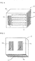
- Fig. 2 is a perspective diagram illustrating the inner structure of the outdoor unit for the air-conditioning apparatus, from a rear face side, in one embodiment of the present invention.
- Fig. 3 is a plan view illustrating the inner structure of the outdoor unit for the air-conditioning apparatus, in one embodiment of the present invention. Note that, in Fig. 2 , the inside of a machine chamber 2 is omitted.
- an outdoor unit 1 for the air-conditioning apparatus in the present embodiment is configured with a casing 14 whose outline having a substantially rectangular parallelepiped shape.
- the casing 14 is configured by assembling an L-shaped front side face panel, a right side face panel, a bottom face panel, a top face panel, and a rear face panel.
- the inside of the casing 14 is partitioned by partition plates 8 to 10, each of which is made of a metal plate, so that the outdoor unit 1 includes a plurality of accommodating chambers adjacent to each other.
- Such accommodating chambers include four chambers that are the machine chamber 2, an electric component chamber 3, a ventilation chamber 4, and a heat exchanger chamber 5.
- an air outlet formed in a circular shape is arranged at the front side face panel.
- the air outlet is covered with a fan guard.
- an air inlet for sucking external air into the ventilation chamber 4 is arranged at the rear face panel.
- a louver 16 with inflow openings facing downward is attached to the air inlet.
- the louver 16 has a configuration in which, as an example, slats each having a window blind shape facing downward are fixed in parallel to each other.
- the machine chamber 2 and the heat exchanger chamber 5 are partitioned by a partition plate 10.
- the electric component chamber 3 and the ventilation chamber 4 are partitioned by a partition plate 9.
- the electric component chamber 3 and the heat exchanger chamber 5 are partitioned by the partition plate 10, the electric component chamber 3 and the ventilation chamber 4 are partitioned by a partition plate 8, and the electric component chamber 3 and the machine chamber 2 are partitioned by a partition plate 9.
- an electric power board 11 on which a power module, a semiconductor, a microcomputer, and other elements for an inverter are mounted, and a control board 12 for controlling the rotation speed, for example, of the compressor 18 are accommodated.
- the control board 12 is configured with, for example, hardware such as a circuit device to enable its functions or software to be executed on an arithmetic device such as a microcomputer or CPU.
- the electric power board 11 is assembled with a rear face side contacting the partition plate 8, which partitions between the ventilation chamber 4 and the electric component chamber 3.
- the control board 12 is arranged to be separated by a space S from the electric power board 11.
- the partition plate 10 has an opening for allowing communication between the electric component chamber 3 and the heat exchanger chamber 5 with the opening formed at a position of the gap of the space S.
- the ventilation chamber 4 are partitioned off from the heat exchanger chamber 5 by the partition plate 10, are partitioned off from the electric component chamber 3 by the partition plate 8, and partitioned off from the machine chamber 2 by a partition plate 9.
- the external air is allowed to pass into the casing 14 through the air inlet (the louver 16) formed at the casing 14.
- a heat sink 6 for cooling the electric power board 11 accommodated in the electric component chamber 3 is accommodated.
- Fig. 4 is a perspective view schematically illustrating a heat sink included in the outdoor unit for the air-conditioning apparatus, in one embodiment of the present invention.
- the heat sink 6 is a metal plate made of aluminum, copper, or the like, with an excellent heat dissipation, and includes a base plate in a flat plate shape (not illustrated) and a plurality of standing cooling fins 61, which are spaced apart from each other, on the top face of base plate.
- the heat sink 6 is secured on the inside of a frame body 60 made of, for example, metal such as aluminum or copper, or resin.
- the frame body 60 including the heat sink 6 therein is attached to the partition plate 8 for partitioning between the electric component chamber 3 and the ventilation chamber 4. At a position facing the heat sink 6 through the partition plate 8, the electric power board 11 in the electric component chamber 3 is disposed.
- a heat sink inlet 6a serving as an opening for sucking into the heat sink 6 the external air that has flown into the ventilation chamber 4, is formed at a position facing the louver 16.
- a heat sink outlet 6b serving as an opening for discharging the air that has flown into the heat sink 6, is formed on a side face facing the heat exchanger chamber 5. That is, in the heat sink 6, the external air that has been sucked into the ventilation chamber 4 is taken from the louver 16 arranged on the side face of the casing 14 into the heat sink 6 through the heat sink inlet 6a, and is discharged from the heat sink 6 through heat sink outlet 6b.
- the heat sink 6 is configured such that the heat sink inlet 6a is arranged to face the louver 16. This configuration facilitates the external air that has flown from the louver 16 to be taken into the heat sink 6, and enhances a cooling effect.
- the cooling fins 61 of the heat sink 6, as illustrated in Fig. 4 are horizontally arranged to be spaced apart from each other. This configuration minimizes resistance to the wind that has entered, and enhances the cooling effect, while ensuring the wind amount sufficiently.
- the cooling fins 61 are not limited to the configuration in which the cooling fins 61 are horizontally arranged, and may have another configuration with another arrangement.
- a ventilation passage 80 for allowing communication between the ventilation chamber 4 and the electric component chamber 3 is formed in the partition plate 8, which partitions between the ventilation chamber 4 and the electric component chamber 3, a ventilation passage 80 for allowing communication between the ventilation chamber 4 and the electric component chamber 3 is formed.
- the ventilation passage 80 is formed to supply the external air that has been sucked from the ventilation chamber 4 to the electric component chamber 3 through the ventilation passage 80.
- the ventilation passage 80 is formed as a rectangular cutout at a corner of an upper end of the partition plate 8. The reason why the ventilation passage 80 is formed at the corner of the upper end of the partition plate 8 is to prevent water droplets generated in the casing 14 from entering the electric component chamber 3. The water droplets drip downward because of gravity effects, and are not capable of passing over the ventilation passage 80.
- the ventilation passage 80 may be formed near the upper end of the partition plate 8, but is not limited to being formed near the upper end, as illustrated. Additionally, the ventilation passage 80 is desirably formed near the upper end of the partition plate 8, but may be provided in a lower area of the partition plate 8. Furthermore, a plurality of ventilation passages 80 may be configured in parallel with each other.
- the ventilation passage 80 is not limited to a rectangular cutout, and may be, for example, a circular one.
- the ventilation passage 80 can allow communication between the electric component chamber 3 and the ventilation chamber 4 to allow the air in the ventilation chamber 4 to flow into the electric component chamber 3.
- the position, shape, and size of the ventilation passage 80 may be changed in consideration of a carried-out situation, as appropriate.
- the heat exchanger chamber 5 is partitioned by the partition plate 10 from the machine chamber 2, the ventilation chamber 4, and the electric component chamber 3.
- an outdoor heat exchanger 7, an outdoor fan 15, and an outdoor fan motor (not illustrated) are accommodated.
- a duct 13 for allowing communication between the heat exchanger chamber 5 and the ventilation chamber 4, and for allowing communication between the heat exchanger chamber 5 and the electric component chamber 3, is provided.
- the outdoor heat exchanger 7, as illustrated in Fig. 3 has for example, a letter L shape in plan view, and is provided along a left side face part in the front side face panel and along the rear face panel.
- the outdoor fan 15 serves as an air-sending unit configured with, for example, a propeller fan, and generates air circulation for heat exchange in an effective manner.
- the outdoor fan 15 has a function of sucking the external air into the outdoor unit 1 from the rear face side of the outdoor unit 1, and blowing out the external air that has been sucked into the outdoor unit 1 towards the front face side of the outdoor unit 1.
- the outdoor fan motor serves as a driving unit configured to drive the outdoor fan 15, and is attached to a support plate provided in the heat exchanger chamber 5 using securing means, for example, a screw.
- Fig. 5 is a perspective diagram schematically illustrating a duct included in the outdoor unit for the air-conditioning apparatus, in one embodiment of the present invention.
- the duct 13 is illustrated when viewed from the rear face side.
- the duct 13 is provided for smoothly sucking wind from the ventilation chamber 4 and the electric component chamber 3 into the heat exchanger chamber 5.
- the duct 13, as illustrated in Figs. 1 to 3 is attached to the partition plate 10, and extends over the partition plate 8, which partitions between the ventilation chamber 4 and the electric component chamber 3.
- a first duct inlet 13a in communication with the ventilation chamber 4 and a second duct inlet 13b in communication with the electric component chamber 3 are formed on the rear face of the duct 13.
- the duct 13 includes an opening face facing downward on the heat exchanger chamber 5 side, as a duct outlet 13c for discharging the air that has flown into the duct 13.
- the first duct inlet 13a in communication with the ventilation chamber 4 is in communication with the heat sink outlet 6b of the heat sink 6 accommodated in the ventilation chamber 4.
- the air that has been discharged from the heat sink outlet 6b flows from the first duct inlet 13a into the duct 13, and flows out of the duct outlet 13c into the heat exchanger chamber 5.
- the second duct inlet 13b in communication with the electric component chamber 3 is arranged at a position of the gap defined between the electric power board 11 and the control board 12.
- the partition plate 10 has an opening in communication with the second duct inlet 13b with the opening formed in the partition plate 10 at a position of the gap. The air that has flown into the electric component chamber 3, cools the electric component chamber 3, then flows into the duct 13 from the second duct inlet 13b, and flows out of the duct outlet 13c into the heat exchanger chamber 5.
- the air that flows into the heat sink 6 flows from the heat sink inlet 6a into a frame body 60. After passing through the plurality of cooling fins 61, the air flows out of the heat sink outlet 6b. The air flows into the heat sink 6, and therefore cools the electric power board 11 accommodated in the electric component chamber 3.
- the air that has flown out of the heat sink outlet 6b flows from the first duct inlet 13a in communication with the heat sink outlet 6b into the duct 13. Then, the air changes its direction to flow downward in a vertical direction, and flows out of the duct outlet 13c into the heat exchanger chamber 5. After the air that has flown into the heat exchanger chamber 5 is subject to heat exchange with refrigerant through the outdoor heat exchanger 7, the air blows out of the outlet of the front side face panel by an outdoor fan 15.
- the air that has flown into the electric component chamber 3 through the ventilation passage 80 formed at the partition plate 8 passes through the gap between the control board 12 and the electric power board 11, and flows into the duct 13 from the second duct inlet 13b in communication with the heat exchanger chamber 5. Then, the air changes its direction to flow downward in the vertical direction, and flows out of the duct outlet 13c into the heat exchanger chamber 5. Then, the air that has flown into the heat exchanger chamber 5 is subject to heat exchange with refrigerant through the outdoor heat exchanger 7. After the heat exchange is carried out between the refrigerant and the air, the air is blown out of the outlet of the front side face panel by the outdoor fan 15.
- the ventilation passage 80 for allowing communication between the ventilation chamber 4 and the electric component chamber 3 is formed at the partition plate 8, which partitions between the ventilation chamber 4 and the electric component chamber 3.
- the external air that has sucked by the ventilation chamber 4 is supplied through the ventilation passage 80 to the electric component chamber 3.
- the air that has flown into the electric component chamber 3 is enabled to sufficiently cool the electrical components, such as the control board 12, separated from the heat sink 6 and having a high necessity to be cooled, so that the temperature of the entire electric component chamber 3 is reduced, and a degradation of the electrical components is prevented.
- the heat sink 6 is disposed through the partition plate 8 to be adjacent to the electric power board 11 disposed in the electric component chamber 3.
- the control board 12 is spaced apart from the electric power board 11 by the space S.
- the rear face side of the electric power board 11 is directly cooled by heat sink 6, and the front face side of the electric power board 11 facing the control board 12 is cooled by the air that has flown into the gap between the electric power board 11 and the control board 12. This configuration enhances the cooling effect of cooling the electric power board 11, which generates heat the most.
- the ventilation chamber 4 and the electric component chamber 3 are partitioned from the machine chamber 2 by the partition plate 9.
- the external air that has flown into the ventilation chamber 4 is not allowed to enter the machine chamber 2 having a low necessity to be cooled, but a large amount of wind is allowed to enter the electric component chamber 3 having a high necessity to be cooled.
- the cooling effect is enhanced.
- any sound that is generated in the machine chamber 2 is insulated by the partition plates 9 and 10, and is less likely to be transmitted to the outside from the louver 16. Hence, a noise prevention effect also works.
- the partition plate 8 partitions between the electric component chamber 3 and the ventilation chamber 4, and therefore it becomes difficult for water droplets such as rain that has flown from the louver 16 hardly enter the electric component chamber 3. This configuration prevents corrosion of the electric components disposed in the electric component chamber 3, and maintains the quality.
- the ventilation passage 80 is arranged near the upper part of the partition plate 8. Hence, even in a case where water droplets are generated in the inside of the outdoor unit 1, the water droplets that drip downward because of gravity effects do not pass over the ventilation passage 80. Thus, in the outdoor unit 1, air is allowed to flow into the electric component chamber 3 from the ventilation chamber 4 to cool the electric power board 11 and the control board 12. In addition, liquid is prevented from entering the electric component chamber 3 in an effective manner.
- the duct 13 for allowing communication between the heat exchanger chamber 5 and the ventilation chamber 4, and for allowing communication between the heat exchanger chamber 5 and the electric component chamber 3 is provided with the opening face facing downward, on the heat exchanger chamber 5 side.
- the rain that has entered from the outlet of the heat exchanger chamber 5 is prevented from entering the electric component chamber 3 through the duct 13.
- the electric components that are accommodated in the electric component chamber 3 are prevented from corroding, and the quality is maintained.
- an outdoor fan 15 in a case where an outdoor fan 15 is arranged below the duct 13, an effect of readily sucking wind due to the negative pressure of the outdoor fan 15 into the inside works.
- the heat sink 6 is arranged in the frame body 60 having an opening (the heat sink inlet 6a) at a position facing the inlet formed in the casing 14. Hence, the external air that has been sucked from the louver 16 is readily supplied into the inside through the opening, and the cooling effect is enhanced.
- the cooling fins 61 of the heat sink 6 are arranged horizontally. This configuration minimizes resistance to the wind that has entered the frame body 60, secures a sufficient amount of wind, and enhances the cooling effect.
- the louver 16 including inflow openings facing downward is provided at the inlet of the casing 14. This configuration makes it difficult for rain to enter the ventilation chamber 4 even at the time of a storm, and also prevents the rain from entering the electric component chamber 3. Accordingly, in the outdoor unit 1, the electric parts are prevented from corroding caused by entering of the rain, and the quality is maintained.
- the present invention has been described based on the embodiments, but the present invention is not limited to the configurations in the above-described embodiments.
- the accommodating chambers other than the members described above, different members may be accommodated.
- the duct 13 may be provided individually for the ventilation chamber 4 and the electric component chamber 3.
- various changes, applications, use ranges that are made as needed by so-called those skilled in the art are also included in subject matters (technical scope) of the present invention.
Abstract
Description
- The present invention relates to an outdoor unit for an air-conditioning apparatus, the outdoor unit having a function of enhancing a cooling capacity of cooling electric components that generate heat.
- Regarding an outdoor unit for an air-conditioning apparatus, typically, a configuration is known that the inside of a casing constituting the outline is partitioned by partition plates to include a plurality of chambers such as a machine chamber, an electric component chamber, and a ventilator chamber. In such an electric component chamber, electric components such as an electric power board for driving a compressor disposed in the machine chamber, and a control board for controlling a refrigerant circuit configured with a compressor and other devices are accommodated. The electric components generate heat while the air-conditioning apparatus is being driven. In a case where heat release is not enough and the electric components become too high in temperature, the boards may be damaged by expansion caused by heat, characteristics of the semiconductors may change, or components on the boards may be degraded. Hence, in the outdoor unit for the air-conditioning apparatus, various ventilation passages are designed to reduce the heat generation by the electric components.
- For example, in Patent Literature 1, a ventilator chamber including propeller fans, and a machine chamber including an electric component box are partitioned by a partition plate. The machine chamber includes a compressor chamber including a compressor, and a ventilation passage chamber for allowing communication between the ventilator chamber and the outside. The compressor chamber and the ventilation passage chamber are partitioned by an electric component box having the top face on which a radiation fin is attached. In the electric component box, an electric power board for driving the compressor, for example, and a control board for controlling a refrigerant circuit are accommodated.
- Patent Literature 1: Japanese Unexamined Utility Model Application Publication No.
H6-35835 - In the configuration where the radiation fin is attached on the top face of the electric component box, as is the case with the outdoor unit for the air-conditioning apparatus of Patent Literature 1, only electric components disposed near the top face of the electric component box in contact with the radiation fin can be cooled. The electric components disposed at positions apart from the radiation fin cannot be cooled in a sufficient manner. That is, in the outdoor unit for the air-conditioning apparatus of Patent Literature 1, the entire electric component box cannot be cooled in a sufficient manner. Hence, releasing of heat that is generated from the electric components is not enough, and the electric components become too high in temperature. This may lead to a situation where the boards are damaged by expansion caused by heat, characteristics of the semiconductors change, or components on the boards are degraded.
- The present invention has been made to address the above-described issue, and has an object to provide an outdoor unit for an air-conditioning apparatus to reduce the temperature of the entire electric component chamber in which an electric power board and a control board are disposed, so that electric components are cooled in a sufficient manner, and a degradation of the electric components is prevented.
- In an outdoor unit for an air-conditioning apparatus, in one embodiment of the present invention, the outdoor unit includes a plurality of accommodating chambers that are respectively adjacent to each other, and the plurality of accommodating chambers are formed by partitioning a casing including an air inlet and an air outlet wit partition plates. The plurality of accommodating chambers includes: a machine chamber in which a refrigerant circuit including a compressor is disposed; an electric component chamber in which an electric power board for driving the compressor and a control board for controlling the compressor are disposed; a ventilation chamber, in which a heat sink including a cooling fin is disposed, configured to suck external air through the air inlet of the casing; and a heat exchanger chamber in which a heat exhanger and a fan are disposed. A partition plate configured to partition between the ventilation chamber and the electric component chamber includes a ventilation passage configured to allow communication between the ventilation chamber and the electric component chamber.
- According to the outdoor unit for the air-conditioning apparatus, in one embodiment of the present invention, the ventilation passage configured to supply the external air that has been taken in from the ventilation chamber to the electric component chamber is arranged at the partition plate configured to partition between the ventilation chamber for taking in the external air through the air inlet and the electric component chamber including the electric power board and the control board. Therefore, the wind that has flown into the electric component chamber cools the electric components that are separated from a heat sink and reduces the temperature of the entire electric component chamber, so that a degradation of the electric components is prevented.
-
- [
Fig. 1] Fig. 1 is a perspective diagram illustrating an inner structure of an outdoor unit for an air-conditioning apparatus, from a front face side, in one embodiment of the present invention. - [
Fig. 2] Fig. 2 is a perspective diagram illustrating the inner structure of the outdoor unit for the air-conditioning apparatus, from a rear face side, in one embodiment of the present invention. - [
Fig. 3] Fig. 3 is a plan view illustrating the inner structure of the outdoor unit for the air-conditioning apparatus, in one embodiment of the present invention. - [
Fig. 4] Fig. 4 is a perspective view schematically illustrating a heat sink constituting the outdoor unit for the air-conditioning apparatus, in one embodiment of the present invention. - [
Fig. 5] Fig. 5 is a perspective diagram schematically illustrating a duct constituting the outdoor unit for the air-conditioning apparatus, in one embodiment of the present invention. - Hereinafter, embodiments of the present invention will be described with reference to the accompanying drawings. Note that in each of the drawings, identical or corresponding parts are applied with identical symbols and their descriptions will be omitted or simplified as appropriate. In addition, with regard to each configuration illustrated in each of the drawings, its shape, size, and arrangement can be changed as appropriate within the scope of the present invention.
-
Fig. 1 is a perspective diagram illustrating an inner structure of an outdoor unit for an air-conditioning apparatus, from a front face side, in one embodiment of the present invention.Fig. 2 is a perspective diagram illustrating the inner structure of the outdoor unit for the air-conditioning apparatus, from a rear face side, in one embodiment of the present invention.Fig. 3 is a plan view illustrating the inner structure of the outdoor unit for the air-conditioning apparatus, in one embodiment of the present invention. Note that, inFig. 2 , the inside of amachine chamber 2 is omitted. - As illustrated in
Figs. 1 and2 , an outdoor unit 1 for the air-conditioning apparatus in the present embodiment is configured with acasing 14 whose outline having a substantially rectangular parallelepiped shape. Thecasing 14 is configured by assembling an L-shaped front side face panel, a right side face panel, a bottom face panel, a top face panel, and a rear face panel. In the outdoor unit 1, as illustrated inFigs. 1 to 3 , the inside of thecasing 14 is partitioned bypartition plates 8 to 10, each of which is made of a metal plate, so that the outdoor unit 1 includes a plurality of accommodating chambers adjacent to each other. Such accommodating chambers include four chambers that are themachine chamber 2, anelectric component chamber 3, aventilation chamber 4, and aheat exchanger chamber 5. Note that although not illustrated in detail, an air outlet formed in a circular shape, as an example, is arranged at the front side face panel. The air outlet is covered with a fan guard. Additionally, an air inlet for sucking external air into theventilation chamber 4 is arranged at the rear face panel. To the air inlet, alouver 16 with inflow openings facing downward is attached. Note that thelouver 16 has a configuration in which, as an example, slats each having a window blind shape facing downward are fixed in parallel to each other. - The
machine chamber 2 and theheat exchanger chamber 5 are partitioned by apartition plate 10. Theelectric component chamber 3 and theventilation chamber 4 are partitioned by apartition plate 9. In themachine chamber 2, acompressor 18 disposed on the bottom face panel of thecasing 14, and arefrigerant circuit 17, in which a four-way valve, an expansion valve, an indoor unit and the like are connected by refrigerant pipes, are accommodated. - The
electric component chamber 3 and theheat exchanger chamber 5 are partitioned by thepartition plate 10, theelectric component chamber 3 and theventilation chamber 4 are partitioned by apartition plate 8, and theelectric component chamber 3 and themachine chamber 2 are partitioned by apartition plate 9. In theelectric component chamber 3, anelectric power board 11, on which a power module, a semiconductor, a microcomputer, and other elements for an inverter are mounted, and acontrol board 12 for controlling the rotation speed, for example, of thecompressor 18 are accommodated. Thecontrol board 12 is configured with, for example, hardware such as a circuit device to enable its functions or software to be executed on an arithmetic device such as a microcomputer or CPU. Theelectric power board 11 is assembled with a rear face side contacting thepartition plate 8, which partitions between theventilation chamber 4 and theelectric component chamber 3. Thecontrol board 12 is arranged to be separated by a space S from theelectric power board 11. Thepartition plate 10 has an opening for allowing communication between theelectric component chamber 3 and theheat exchanger chamber 5 with the opening formed at a position of the gap of the space S. - The
ventilation chamber 4 are partitioned off from theheat exchanger chamber 5 by thepartition plate 10, are partitioned off from theelectric component chamber 3 by thepartition plate 8, and partitioned off from themachine chamber 2 by apartition plate 9. The external air is allowed to pass into thecasing 14 through the air inlet (the louver 16) formed at thecasing 14. In theventilation chamber 4, as illustrated inFigs. 1 to 3 , aheat sink 6 for cooling theelectric power board 11 accommodated in theelectric component chamber 3 is accommodated. -
Fig. 4 is a perspective view schematically illustrating a heat sink included in the outdoor unit for the air-conditioning apparatus, in one embodiment of the present invention. Theheat sink 6 is a metal plate made of aluminum, copper, or the like, with an excellent heat dissipation, and includes a base plate in a flat plate shape (not illustrated) and a plurality of standingcooling fins 61, which are spaced apart from each other, on the top face of base plate. Theheat sink 6 is secured on the inside of aframe body 60 made of, for example, metal such as aluminum or copper, or resin. Theframe body 60 including theheat sink 6 therein is attached to thepartition plate 8 for partitioning between theelectric component chamber 3 and theventilation chamber 4. At a position facing theheat sink 6 through thepartition plate 8, theelectric power board 11 in theelectric component chamber 3 is disposed. - In the
frame body 60 of theheat sink 6, aheat sink inlet 6a, serving as an opening for sucking into theheat sink 6 the external air that has flown into theventilation chamber 4, is formed at a position facing thelouver 16. Additionally, in theframe body 60 of theheat sink 6, a heat sink outlet 6b, serving as an opening for discharging the air that has flown into theheat sink 6, is formed on a side face facing theheat exchanger chamber 5. That is, in theheat sink 6, the external air that has been sucked into theventilation chamber 4 is taken from thelouver 16 arranged on the side face of thecasing 14 into theheat sink 6 through theheat sink inlet 6a, and is discharged from theheat sink 6 through heat sink outlet 6b. Theheat sink 6 is configured such that theheat sink inlet 6a is arranged to face thelouver 16. This configuration facilitates the external air that has flown from thelouver 16 to be taken into theheat sink 6, and enhances a cooling effect. - The cooling
fins 61 of theheat sink 6, as illustrated inFig. 4 , are horizontally arranged to be spaced apart from each other. This configuration minimizes resistance to the wind that has entered, and enhances the cooling effect, while ensuring the wind amount sufficiently. However, the coolingfins 61 are not limited to the configuration in which thecooling fins 61 are horizontally arranged, and may have another configuration with another arrangement. - In the
partition plate 8, which partitions between theventilation chamber 4 and theelectric component chamber 3, aventilation passage 80 for allowing communication between theventilation chamber 4 and theelectric component chamber 3 is formed. Theventilation passage 80 is formed to supply the external air that has been sucked from theventilation chamber 4 to theelectric component chamber 3 through theventilation passage 80. Theventilation passage 80 is formed as a rectangular cutout at a corner of an upper end of thepartition plate 8. The reason why theventilation passage 80 is formed at the corner of the upper end of thepartition plate 8 is to prevent water droplets generated in thecasing 14 from entering theelectric component chamber 3. The water droplets drip downward because of gravity effects, and are not capable of passing over theventilation passage 80. Therefore, in the outdoor unit 1, a certain amount of wind is allowed to flow into theelectric component chamber 3 from theventilation chamber 4 through theventilation passage 80, to cool theelectric power board 11 and thecontrol board 12, and to prevent water droplets from entering theelectric component chamber 3 in an effective manner. Note that theventilation passage 80 may be formed near the upper end of thepartition plate 8, but is not limited to being formed near the upper end, as illustrated. Additionally, theventilation passage 80 is desirably formed near the upper end of thepartition plate 8, but may be provided in a lower area of thepartition plate 8. Furthermore, a plurality ofventilation passages 80 may be configured in parallel with each other. Theventilation passage 80 is not limited to a rectangular cutout, and may be, for example, a circular one. In brief, theventilation passage 80 can allow communication between theelectric component chamber 3 and theventilation chamber 4 to allow the air in theventilation chamber 4 to flow into theelectric component chamber 3. The position, shape, and size of theventilation passage 80 may be changed in consideration of a carried-out situation, as appropriate. - The
heat exchanger chamber 5 is partitioned by thepartition plate 10 from themachine chamber 2, theventilation chamber 4, and theelectric component chamber 3. In theheat exchanger chamber 5, anoutdoor heat exchanger 7, anoutdoor fan 15, and an outdoor fan motor (not illustrated) are accommodated. Additionally, in theheat exchanger chamber 5, aduct 13, for allowing communication between theheat exchanger chamber 5 and theventilation chamber 4, and for allowing communication between theheat exchanger chamber 5 and theelectric component chamber 3, is provided. - The
outdoor heat exchanger 7, as illustrated inFig. 3 , has for example, a letter L shape in plan view, and is provided along a left side face part in the front side face panel and along the rear face panel. Theoutdoor fan 15 serves as an air-sending unit configured with, for example, a propeller fan, and generates air circulation for heat exchange in an effective manner. Theoutdoor fan 15 has a function of sucking the external air into the outdoor unit 1 from the rear face side of the outdoor unit 1, and blowing out the external air that has been sucked into the outdoor unit 1 towards the front face side of the outdoor unit 1. The outdoor fan motor serves as a driving unit configured to drive theoutdoor fan 15, and is attached to a support plate provided in theheat exchanger chamber 5 using securing means, for example, a screw. -
Fig. 5 is a perspective diagram schematically illustrating a duct included in the outdoor unit for the air-conditioning apparatus, in one embodiment of the present invention. InFig. 5 , theduct 13 is illustrated when viewed from the rear face side. Theduct 13 is provided for smoothly sucking wind from theventilation chamber 4 and theelectric component chamber 3 into theheat exchanger chamber 5. Theduct 13, as illustrated inFigs. 1 to 3 , is attached to thepartition plate 10, and extends over thepartition plate 8, which partitions between theventilation chamber 4 and theelectric component chamber 3. As illustrated inFig. 5 , afirst duct inlet 13a in communication with theventilation chamber 4 and asecond duct inlet 13b in communication with theelectric component chamber 3 are formed on the rear face of theduct 13. Also, theduct 13 includes an opening face facing downward on theheat exchanger chamber 5 side, as aduct outlet 13c for discharging the air that has flown into theduct 13. - The
first duct inlet 13a in communication with theventilation chamber 4 is in communication with the heat sink outlet 6b of theheat sink 6 accommodated in theventilation chamber 4. The air that has been discharged from the heat sink outlet 6b flows from thefirst duct inlet 13a into theduct 13, and flows out of theduct outlet 13c into theheat exchanger chamber 5. - On the other hand, the
second duct inlet 13b in communication with theelectric component chamber 3 is arranged at a position of the gap defined between theelectric power board 11 and thecontrol board 12. Thepartition plate 10 has an opening in communication with thesecond duct inlet 13b with the opening formed in thepartition plate 10 at a position of the gap. The air that has flown into theelectric component chamber 3, cools theelectric component chamber 3, then flows into theduct 13 from thesecond duct inlet 13b, and flows out of theduct outlet 13c into theheat exchanger chamber 5. - Here, based on
Figs. 1 to 3 , the flow of the air through the outdoor unit 1 will be described. In the outdoor unit 1 for the air-conditioning apparatus in the present embodiment, when theoutdoor fan 15 accommodated in theheat exchanger chamber 5 rotates, the inside of theheat exchanger chamber 5 becomes negative in pressure. Hence, as illustrated inFig. 2 , the external air flows into theventilation chamber 4 from thelouver 16. The external air that has flown into theventilation chamber 4 divides into air to flow into theheat sink 6, and air to flow into theelectric component chamber 3 through theventilation passage 80 formed at thepartition plate 8, which partitions between theventilation chamber 4 and theelectric component chamber 3. - The air that flows into the
heat sink 6 flows from theheat sink inlet 6a into aframe body 60. After passing through the plurality of coolingfins 61, the air flows out of the heat sink outlet 6b. The air flows into theheat sink 6, and therefore cools theelectric power board 11 accommodated in theelectric component chamber 3. The air that has flown out of the heat sink outlet 6b flows from thefirst duct inlet 13a in communication with the heat sink outlet 6b into theduct 13. Then, the air changes its direction to flow downward in a vertical direction, and flows out of theduct outlet 13c into theheat exchanger chamber 5. After the air that has flown into theheat exchanger chamber 5 is subject to heat exchange with refrigerant through theoutdoor heat exchanger 7, the air blows out of the outlet of the front side face panel by anoutdoor fan 15. - On the other hand, the air that has flown into the
electric component chamber 3 through theventilation passage 80 formed at thepartition plate 8 passes through the gap between thecontrol board 12 and theelectric power board 11, and flows into theduct 13 from thesecond duct inlet 13b in communication with theheat exchanger chamber 5. Then, the air changes its direction to flow downward in the vertical direction, and flows out of theduct outlet 13c into theheat exchanger chamber 5. Then, the air that has flown into theheat exchanger chamber 5 is subject to heat exchange with refrigerant through theoutdoor heat exchanger 7. After the heat exchange is carried out between the refrigerant and the air, the air is blown out of the outlet of the front side face panel by theoutdoor fan 15. - In the outdoor unit 1 for the air-conditioning apparatus in the present embodiment, the
ventilation passage 80 for allowing communication between theventilation chamber 4 and theelectric component chamber 3 is formed at thepartition plate 8, which partitions between theventilation chamber 4 and theelectric component chamber 3. Hence, the external air that has sucked by theventilation chamber 4 is supplied through theventilation passage 80 to theelectric component chamber 3. Thus, in the outdoor unit 1, the air that has flown into theelectric component chamber 3 is enabled to sufficiently cool the electrical components, such as thecontrol board 12, separated from theheat sink 6 and having a high necessity to be cooled, so that the temperature of the entireelectric component chamber 3 is reduced, and a degradation of the electrical components is prevented. - Additionally, in the outdoor unit 1, the
heat sink 6 is disposed through thepartition plate 8 to be adjacent to theelectric power board 11 disposed in theelectric component chamber 3. Thecontrol board 12 is spaced apart from theelectric power board 11 by the space S. Thus, in the outdoor unit 1, the rear face side of theelectric power board 11 is directly cooled byheat sink 6, and the front face side of theelectric power board 11 facing thecontrol board 12 is cooled by the air that has flown into the gap between theelectric power board 11 and thecontrol board 12. This configuration enhances the cooling effect of cooling theelectric power board 11, which generates heat the most. - Further, in the outdoor unit 1, the
ventilation chamber 4 and theelectric component chamber 3 are partitioned from themachine chamber 2 by thepartition plate 9. The external air that has flown into theventilation chamber 4 is not allowed to enter themachine chamber 2 having a low necessity to be cooled, but a large amount of wind is allowed to enter theelectric component chamber 3 having a high necessity to be cooled. Thus, the cooling effect is enhanced. Moreover, in the outdoor unit 1, any sound that is generated in themachine chamber 2 is insulated by thepartition plates louver 16. Hence, a noise prevention effect also works. - Additionally, in the outdoor unit 1, the
partition plate 8 partitions between theelectric component chamber 3 and theventilation chamber 4, and therefore it becomes difficult for water droplets such as rain that has flown from thelouver 16 hardly enter theelectric component chamber 3. This configuration prevents corrosion of the electric components disposed in theelectric component chamber 3, and maintains the quality. - Further, in the outdoor unit 1, the
ventilation passage 80 is arranged near the upper part of thepartition plate 8. Hence, even in a case where water droplets are generated in the inside of the outdoor unit 1, the water droplets that drip downward because of gravity effects do not pass over theventilation passage 80. Thus, in the outdoor unit 1, air is allowed to flow into theelectric component chamber 3 from theventilation chamber 4 to cool theelectric power board 11 and thecontrol board 12. In addition, liquid is prevented from entering theelectric component chamber 3 in an effective manner. - Further, in the outdoor unit 1, the
duct 13 for allowing communication between theheat exchanger chamber 5 and theventilation chamber 4, and for allowing communication between theheat exchanger chamber 5 and theelectric component chamber 3 is provided with the opening face facing downward, on theheat exchanger chamber 5 side. Hence, for example, even at the time of a rainstorm, the rain that has entered from the outlet of theheat exchanger chamber 5 is prevented from entering theelectric component chamber 3 through theduct 13. Thus, in the outdoor unit 1, the electric components that are accommodated in theelectric component chamber 3 are prevented from corroding, and the quality is maintained. Also, in the outdoor unit 1, in a case where anoutdoor fan 15 is arranged below theduct 13, an effect of readily sucking wind due to the negative pressure of theoutdoor fan 15 into the inside works. - Further, in the outdoor unit 1, the
heat sink 6 is arranged in theframe body 60 having an opening (theheat sink inlet 6a) at a position facing the inlet formed in thecasing 14. Hence, the external air that has been sucked from thelouver 16 is readily supplied into the inside through the opening, and the cooling effect is enhanced. - Further, in the outdoor unit 1, the cooling
fins 61 of theheat sink 6 are arranged horizontally. This configuration minimizes resistance to the wind that has entered theframe body 60, secures a sufficient amount of wind, and enhances the cooling effect. - Further, in the outdoor unit 1, the
louver 16 including inflow openings facing downward is provided at the inlet of thecasing 14. This configuration makes it difficult for rain to enter theventilation chamber 4 even at the time of a storm, and also prevents the rain from entering theelectric component chamber 3. Accordingly, in the outdoor unit 1, the electric parts are prevented from corroding caused by entering of the rain, and the quality is maintained. - Heretofore, the present invention has been described based on the embodiments, but the present invention is not limited to the configurations in the above-described embodiments. For example, in each of the accommodating chambers, other than the members described above, different members may be accommodated. Additionally, the
duct 13 may be provided individually for theventilation chamber 4 and theelectric component chamber 3. In brief, it is to be noted that various changes, applications, use ranges that are made as needed by so-called those skilled in the art are also included in subject matters (technical scope) of the present invention. -
- 1 outdoor unit, 2 machine chamber, 3 electric component chamber,
- 4 ventilation chamber, 5 heat exchanger chamber, 6 heat sink, 6a heat sink inlet, 6b heat sink outlet, 7 outdoor heat exchanger, 8, 9, 10 partition plate, 11 electric power board, 12 control board, 13 duct, 13a first duct inlet, 13b second duct inlet, 13c duct outlet, 14 casing, 15 outdoor fan, 16 louver, 17 refrigerant circuit, 18 compressor, 60 frame body, 61 cooling fin, 80 ventilation passage
Claims (7)
- An outdoor unit for an air-conditioning apparatus, comprising
a plurality of accommodating chambers that are respectively adjacent to each other, the plurality of accommodating chambers formed by partitioning a casing including an air inlet and an air outlet with a partition plate,
wherein the plurality of accommodating chambers includes
a machine chamber in which a refrigerant circuit including a compressor is disposed,
an electric component chamber in which an electric power board configured to drive the compressor and a control board configured to control the compressor are disposed,
a ventilation chamber, in which a heat sink including cooling fins is disposed, configured to suck external air through the air inlet of the casing, and
a heat exchanger chamber in which a heat exchanger and a fan are disposed, and
wherein the partition plate configured to partition between the ventilation chamber and the electric component chamber includes a ventilation passage configured to allow communication between the ventilation chamber and the electric component chamber. - The outdoor unit for the air-conditioning apparatus of claim 1,
wherein the heat sink is arranged to be adjacent to the electric power board disposed in the electric component chamber through the partition plate and
wherein the control board is arranged to be spaced apart from the electric power board. - The outdoor unit for the air-conditioning apparatus of claims 1 or 2, wherein the ventilation passage is provided in a proximity of an upper end of the partition plate configured to partition between the ventilation chamber and the electric component chamber.
- The outdoor unit for the air-conditioning apparatus of any one of claim 1 to claim 3, wherein the heat exchanger chamber includes a duct with an opening face facing downward on a heat exchanger chamber side, the duct being configured to allow communication between the heat exchanger chamber and the ventilation chamber, and to allow communication between the heat exchanger chamber and the electric component chamber.
- The outdoor unit for the air-conditioning apparatus of any one of claim 1 to claim 4, wherein the heat sink is disposed in a frame body having an opening arranged at a position facing the air inlet of the casing.
- The outdoor unit for the air-conditioning apparatus of any one of claim 1 to claim 5, wherein the cooling fins of the heat sink are arranged in a horizontal direction.
- The outdoor unit for the air-conditioning apparatus of any one of claim 1 to claim 6, wherein a louver with an inflow opening facing downward is provided at the air inlet of the casing.
Applications Claiming Priority (1)
| Application Number | Priority Date | Filing Date | Title |
|---|---|---|---|
| PCT/JP2016/078354 WO2018061071A1 (en) | 2016-09-27 | 2016-09-27 | Outdoor unit of air conditioner |
Publications (3)
| Publication Number | Publication Date |
|---|---|
| EP3327362A1 true EP3327362A1 (en) | 2018-05-30 |
| EP3327362A4 EP3327362A4 (en) | 2018-11-07 |
| EP3327362B1 EP3327362B1 (en) | 2019-09-11 |
Family
ID=61760226
Family Applications (1)
| Application Number | Title | Priority Date | Filing Date |
|---|---|---|---|
| EP16904839.4A Active EP3327362B1 (en) | 2016-09-27 | 2016-09-27 | Outdoor unit of air conditioner |
Country Status (4)
| Country | Link |
|---|---|
| EP (1) | EP3327362B1 (en) |
| JP (1) | JP6632733B2 (en) |
| CN (1) | CN207778627U (en) |
| WO (1) | WO2018061071A1 (en) |
Cited By (1)
| Publication number | Priority date | Publication date | Assignee | Title |
|---|---|---|---|---|
| EP4083523A1 (en) * | 2021-04-27 | 2022-11-02 | Panasonic Intellectual Property Management Co., Ltd. | Heat medium circulation device |
Families Citing this family (1)
| Publication number | Priority date | Publication date | Assignee | Title |
|---|---|---|---|---|
| US11906177B2 (en) * | 2018-10-11 | 2024-02-20 | Mitsubishi Electric Corporation | Outdoor unit |
Family Cites Families (10)
| Publication number | Priority date | Publication date | Assignee | Title |
|---|---|---|---|---|
| JPH0635835U (en) | 1992-10-13 | 1994-05-13 | 松下冷機株式会社 | Air conditioner outdoor unit |
| JP2000161717A (en) * | 1998-11-27 | 2000-06-16 | Sharp Corp | Outdoor unit of air conditioner |
| JP4582972B2 (en) * | 2001-08-09 | 2010-11-17 | 東芝キヤリア株式会社 | Air conditioner outdoor unit |
| ES2629957T3 (en) * | 2003-09-25 | 2017-08-16 | Toshiba Carrier Corporation | Outdoor unit of air conditioner |
| JP4663290B2 (en) * | 2004-10-27 | 2011-04-06 | 三洋電機株式会社 | Outdoor unit |
| IT1400737B1 (en) * | 2009-05-20 | 2013-07-02 | Sanyo Electric Co | EXTERNAL UNIT FOR HEAT EXCHANGE, PARTICULARLY IN HEAT EXCHANGERS AND SIMILAR. |
| JP5794816B2 (en) * | 2011-04-15 | 2015-10-14 | 三菱電機株式会社 | Outdoor unit and refrigeration cycle apparatus including the outdoor unit |
| JP5924873B2 (en) * | 2011-05-13 | 2016-05-25 | 三菱電機株式会社 | Control device for air conditioner |
| JP5851303B2 (en) * | 2012-03-28 | 2016-02-03 | 三菱電機株式会社 | Refrigeration cycle apparatus and outdoor heat source unit |
| CN106716022B (en) * | 2014-12-05 | 2019-06-14 | 东芝开利株式会社 | The outdoor unit of refrigerating circulatory device |
-
2016
- 2016-09-27 WO PCT/JP2016/078354 patent/WO2018061071A1/en unknown
- 2016-09-27 CN CN201690000849.1U patent/CN207778627U/en active Active
- 2016-09-27 EP EP16904839.4A patent/EP3327362B1/en active Active
- 2016-09-27 JP JP2018541741A patent/JP6632733B2/en active Active
Cited By (1)
| Publication number | Priority date | Publication date | Assignee | Title |
|---|---|---|---|---|
| EP4083523A1 (en) * | 2021-04-27 | 2022-11-02 | Panasonic Intellectual Property Management Co., Ltd. | Heat medium circulation device |
Also Published As
| Publication number | Publication date |
|---|---|
| JPWO2018061071A1 (en) | 2019-04-25 |
| WO2018061071A1 (en) | 2018-04-05 |
| EP3327362A4 (en) | 2018-11-07 |
| JP6632733B2 (en) | 2020-01-22 |
| EP3327362B1 (en) | 2019-09-11 |
| CN207778627U (en) | 2018-08-28 |
Similar Documents
| Publication | Publication Date | Title |
|---|---|---|
| EP3017255B1 (en) | Air conditioner | |
| JP6214462B2 (en) | Air conditioner outdoor unit | |
| US20090081940A1 (en) | Outdoor unit of air conditioner | |
| CN110785613B (en) | Outdoor unit of refrigerator | |
| US9353968B2 (en) | Heat source unit of refrigerating apparatus | |
| WO2004042287A1 (en) | Outdoor unit of refrigerator, and electrical equipment box of outdoor unit | |
| CN110770507A (en) | Outdoor unit of refrigerator | |
| JP6388252B2 (en) | Electrical equipment | |
| US10845066B2 (en) | Heat source unit of refrigerating apparatus | |
| EP3327362B1 (en) | Outdoor unit of air conditioner | |
| JP2014105948A (en) | Outdoor unit of air conditioner | |
| US10982877B2 (en) | Heat source unit for refrigeration device | |
| JP6298542B2 (en) | Outdoor unit of refrigeration cycle equipment | |
| JP6594428B2 (en) | Air conditioner outdoor unit and air conditioner | |
| US11226119B2 (en) | Heat exchanger unit and air-conditioning apparatus | |
| CN203810590U (en) | Air conditioning electric control box cooling device and air conditioning comprising same | |
| JP2003106569A (en) | Outdoor unit of air conditioner | |
| CN115342445A (en) | Air condensing units and air conditioning equipment | |
| JP2014240713A (en) | Outdoor unit for air conditioner | |
| JP2015161475A (en) | Outdoor unit of air conditioner | |
| WO2020044473A1 (en) | Outdoor unit and air conditioner | |
| WO2021054464A1 (en) | Outdoor unit of refrigeration device | |
| CN216620062U (en) | Integrated air conditioner | |
| KR101539391B1 (en) | Outdoor unit of air conditioner | |
| CN215929866U (en) | Dehumidification device and air conditioner with same |
Legal Events
| Date | Code | Title | Description |
|---|---|---|---|
| STAA | Information on the status of an ep patent application or granted ep patent |
Free format text: STATUS: UNKNOWN |
|
| STAA | Information on the status of an ep patent application or granted ep patent |
Free format text: STATUS: THE INTERNATIONAL PUBLICATION HAS BEEN MADE |
|
| PUAI | Public reference made under article 153(3) epc to a published international application that has entered the european phase |
Free format text: ORIGINAL CODE: 0009012 |
|
| STAA | Information on the status of an ep patent application or granted ep patent |
Free format text: STATUS: REQUEST FOR EXAMINATION WAS MADE |
|
| 17P | Request for examination filed |
Effective date: 20171218 |
|
| AK | Designated contracting states |
Kind code of ref document: A1 Designated state(s): AL AT BE BG CH CY CZ DE DK EE ES FI FR GB GR HR HU IE IS IT LI LT LU LV MC MK MT NL NO PL PT RO RS SE SI SK SM TR |
|
| AX | Request for extension of the european patent |
Extension state: BA ME |
|
| A4 | Supplementary search report drawn up and despatched |
Effective date: 20181008 |
|
| RIC1 | Information provided on ipc code assigned before grant |
Ipc: F24F 1/46 20110101ALI20181001BHEP Ipc: F24F 1/24 20110101AFI20181001BHEP Ipc: F24F 1/54 20110101ALI20181001BHEP |
|
| GRAP | Despatch of communication of intention to grant a patent |
Free format text: ORIGINAL CODE: EPIDOSNIGR1 |
|
| STAA | Information on the status of an ep patent application or granted ep patent |
Free format text: STATUS: GRANT OF PATENT IS INTENDED |
|
| RIC1 | Information provided on ipc code assigned before grant |
Ipc: F24F 1/24 20110101AFI20190315BHEP Ipc: F24F 1/46 20110101ALI20190315BHEP Ipc: F24F 1/54 20110101ALI20190315BHEP |
|
| DAV | Request for validation of the european patent (deleted) | ||
| DAX | Request for extension of the european patent (deleted) | ||
| INTG | Intention to grant announced |
Effective date: 20190405 |
|
| GRAS | Grant fee paid |
Free format text: ORIGINAL CODE: EPIDOSNIGR3 |
|
| GRAA | (expected) grant |
Free format text: ORIGINAL CODE: 0009210 |
|
| STAA | Information on the status of an ep patent application or granted ep patent |
Free format text: STATUS: THE PATENT HAS BEEN GRANTED |
|
| AK | Designated contracting states |
Kind code of ref document: B1 Designated state(s): AL AT BE BG CH CY CZ DE DK EE ES FI FR GB GR HR HU IE IS IT LI LT LU LV MC MK MT NL NO PL PT RO RS SE SI SK SM TR |
|
| REG | Reference to a national code |
Ref country code: GB Ref legal event code: FG4D |
|
| REG | Reference to a national code |
Ref country code: CH Ref legal event code: EP |
|
| REG | Reference to a national code |
Ref country code: AT Ref legal event code: REF Ref document number: 1178922 Country of ref document: AT Kind code of ref document: T Effective date: 20190915 |
|
| REG | Reference to a national code |
Ref country code: DE Ref legal event code: R096 Ref document number: 602016020646 Country of ref document: DE Ref country code: IE Ref legal event code: FG4D |
|
| REG | Reference to a national code |
Ref country code: NL Ref legal event code: MP Effective date: 20190911 |
|
| REG | Reference to a national code |
Ref country code: LT Ref legal event code: MG4D |
|
| PG25 | Lapsed in a contracting state [announced via postgrant information from national office to epo] |
Ref country code: FI Free format text: LAPSE BECAUSE OF FAILURE TO SUBMIT A TRANSLATION OF THE DESCRIPTION OR TO PAY THE FEE WITHIN THE PRESCRIBED TIME-LIMIT Effective date: 20190911 Ref country code: LT Free format text: LAPSE BECAUSE OF FAILURE TO SUBMIT A TRANSLATION OF THE DESCRIPTION OR TO PAY THE FEE WITHIN THE PRESCRIBED TIME-LIMIT Effective date: 20190911 Ref country code: BG Free format text: LAPSE BECAUSE OF FAILURE TO SUBMIT A TRANSLATION OF THE DESCRIPTION OR TO PAY THE FEE WITHIN THE PRESCRIBED TIME-LIMIT Effective date: 20191211 Ref country code: NO Free format text: LAPSE BECAUSE OF FAILURE TO SUBMIT A TRANSLATION OF THE DESCRIPTION OR TO PAY THE FEE WITHIN THE PRESCRIBED TIME-LIMIT Effective date: 20191211 Ref country code: HR Free format text: LAPSE BECAUSE OF FAILURE TO SUBMIT A TRANSLATION OF THE DESCRIPTION OR TO PAY THE FEE WITHIN THE PRESCRIBED TIME-LIMIT Effective date: 20190911 Ref country code: SE Free format text: LAPSE BECAUSE OF FAILURE TO SUBMIT A TRANSLATION OF THE DESCRIPTION OR TO PAY THE FEE WITHIN THE PRESCRIBED TIME-LIMIT Effective date: 20190911 |
|
| PG25 | Lapsed in a contracting state [announced via postgrant information from national office to epo] |
Ref country code: RS Free format text: LAPSE BECAUSE OF FAILURE TO SUBMIT A TRANSLATION OF THE DESCRIPTION OR TO PAY THE FEE WITHIN THE PRESCRIBED TIME-LIMIT Effective date: 20190911 Ref country code: GR Free format text: LAPSE BECAUSE OF FAILURE TO SUBMIT A TRANSLATION OF THE DESCRIPTION OR TO PAY THE FEE WITHIN THE PRESCRIBED TIME-LIMIT Effective date: 20191212 Ref country code: AL Free format text: LAPSE BECAUSE OF FAILURE TO SUBMIT A TRANSLATION OF THE DESCRIPTION OR TO PAY THE FEE WITHIN THE PRESCRIBED TIME-LIMIT Effective date: 20190911 Ref country code: ES Free format text: LAPSE BECAUSE OF FAILURE TO SUBMIT A TRANSLATION OF THE DESCRIPTION OR TO PAY THE FEE WITHIN THE PRESCRIBED TIME-LIMIT Effective date: 20190911 Ref country code: LV Free format text: LAPSE BECAUSE OF FAILURE TO SUBMIT A TRANSLATION OF THE DESCRIPTION OR TO PAY THE FEE WITHIN THE PRESCRIBED TIME-LIMIT Effective date: 20190911 |
|
| REG | Reference to a national code |
Ref country code: AT Ref legal event code: MK05 Ref document number: 1178922 Country of ref document: AT Kind code of ref document: T Effective date: 20190911 |
|
| PG25 | Lapsed in a contracting state [announced via postgrant information from national office to epo] |
Ref country code: EE Free format text: LAPSE BECAUSE OF FAILURE TO SUBMIT A TRANSLATION OF THE DESCRIPTION OR TO PAY THE FEE WITHIN THE PRESCRIBED TIME-LIMIT Effective date: 20190911 Ref country code: PL Free format text: LAPSE BECAUSE OF FAILURE TO SUBMIT A TRANSLATION OF THE DESCRIPTION OR TO PAY THE FEE WITHIN THE PRESCRIBED TIME-LIMIT Effective date: 20190911 Ref country code: AT Free format text: LAPSE BECAUSE OF FAILURE TO SUBMIT A TRANSLATION OF THE DESCRIPTION OR TO PAY THE FEE WITHIN THE PRESCRIBED TIME-LIMIT Effective date: 20190911 Ref country code: IT Free format text: LAPSE BECAUSE OF FAILURE TO SUBMIT A TRANSLATION OF THE DESCRIPTION OR TO PAY THE FEE WITHIN THE PRESCRIBED TIME-LIMIT Effective date: 20190911 Ref country code: PT Free format text: LAPSE BECAUSE OF FAILURE TO SUBMIT A TRANSLATION OF THE DESCRIPTION OR TO PAY THE FEE WITHIN THE PRESCRIBED TIME-LIMIT Effective date: 20200113 Ref country code: RO Free format text: LAPSE BECAUSE OF FAILURE TO SUBMIT A TRANSLATION OF THE DESCRIPTION OR TO PAY THE FEE WITHIN THE PRESCRIBED TIME-LIMIT Effective date: 20190911 Ref country code: NL Free format text: LAPSE BECAUSE OF FAILURE TO SUBMIT A TRANSLATION OF THE DESCRIPTION OR TO PAY THE FEE WITHIN THE PRESCRIBED TIME-LIMIT Effective date: 20190911 |
|
| PG25 | Lapsed in a contracting state [announced via postgrant information from national office to epo] |
Ref country code: SK Free format text: LAPSE BECAUSE OF FAILURE TO SUBMIT A TRANSLATION OF THE DESCRIPTION OR TO PAY THE FEE WITHIN THE PRESCRIBED TIME-LIMIT Effective date: 20190911 Ref country code: CZ Free format text: LAPSE BECAUSE OF FAILURE TO SUBMIT A TRANSLATION OF THE DESCRIPTION OR TO PAY THE FEE WITHIN THE PRESCRIBED TIME-LIMIT Effective date: 20190911 Ref country code: IS Free format text: LAPSE BECAUSE OF FAILURE TO SUBMIT A TRANSLATION OF THE DESCRIPTION OR TO PAY THE FEE WITHIN THE PRESCRIBED TIME-LIMIT Effective date: 20200224 Ref country code: SM Free format text: LAPSE BECAUSE OF FAILURE TO SUBMIT A TRANSLATION OF THE DESCRIPTION OR TO PAY THE FEE WITHIN THE PRESCRIBED TIME-LIMIT Effective date: 20190911 |
|
| REG | Reference to a national code |
Ref country code: CH Ref legal event code: PL |
|
| REG | Reference to a national code |
Ref country code: DE Ref legal event code: R097 Ref document number: 602016020646 Country of ref document: DE |
|
| PLBE | No opposition filed within time limit |
Free format text: ORIGINAL CODE: 0009261 |
|
| STAA | Information on the status of an ep patent application or granted ep patent |
Free format text: STATUS: NO OPPOSITION FILED WITHIN TIME LIMIT |
|
| PG2D | Information on lapse in contracting state deleted |
Ref country code: IS |
|
| PG25 | Lapsed in a contracting state [announced via postgrant information from national office to epo] |
Ref country code: LU Free format text: LAPSE BECAUSE OF NON-PAYMENT OF DUE FEES Effective date: 20190927 Ref country code: LI Free format text: LAPSE BECAUSE OF NON-PAYMENT OF DUE FEES Effective date: 20190930 Ref country code: IE Free format text: LAPSE BECAUSE OF NON-PAYMENT OF DUE FEES Effective date: 20190927 Ref country code: CH Free format text: LAPSE BECAUSE OF NON-PAYMENT OF DUE FEES Effective date: 20190930 Ref country code: DK Free format text: LAPSE BECAUSE OF FAILURE TO SUBMIT A TRANSLATION OF THE DESCRIPTION OR TO PAY THE FEE WITHIN THE PRESCRIBED TIME-LIMIT Effective date: 20190911 Ref country code: IS Free format text: LAPSE BECAUSE OF FAILURE TO SUBMIT A TRANSLATION OF THE DESCRIPTION OR TO PAY THE FEE WITHIN THE PRESCRIBED TIME-LIMIT Effective date: 20200112 |
|
| REG | Reference to a national code |
Ref country code: BE Ref legal event code: MM Effective date: 20190930 |
|
| 26N | No opposition filed |
Effective date: 20200615 |
|
| PG25 | Lapsed in a contracting state [announced via postgrant information from national office to epo] |
Ref country code: BE Free format text: LAPSE BECAUSE OF NON-PAYMENT OF DUE FEES Effective date: 20190930 Ref country code: SI Free format text: LAPSE BECAUSE OF FAILURE TO SUBMIT A TRANSLATION OF THE DESCRIPTION OR TO PAY THE FEE WITHIN THE PRESCRIBED TIME-LIMIT Effective date: 20190911 Ref country code: MC Free format text: LAPSE BECAUSE OF FAILURE TO SUBMIT A TRANSLATION OF THE DESCRIPTION OR TO PAY THE FEE WITHIN THE PRESCRIBED TIME-LIMIT Effective date: 20190911 |
|
| PG25 | Lapsed in a contracting state [announced via postgrant information from national office to epo] |
Ref country code: FR Free format text: LAPSE BECAUSE OF NON-PAYMENT OF DUE FEES Effective date: 20191111 |
|
| PG25 | Lapsed in a contracting state [announced via postgrant information from national office to epo] |
Ref country code: CY Free format text: LAPSE BECAUSE OF FAILURE TO SUBMIT A TRANSLATION OF THE DESCRIPTION OR TO PAY THE FEE WITHIN THE PRESCRIBED TIME-LIMIT Effective date: 20190911 |
|
| PG25 | Lapsed in a contracting state [announced via postgrant information from national office to epo] |
Ref country code: MT Free format text: LAPSE BECAUSE OF FAILURE TO SUBMIT A TRANSLATION OF THE DESCRIPTION OR TO PAY THE FEE WITHIN THE PRESCRIBED TIME-LIMIT Effective date: 20190911 Ref country code: HU Free format text: LAPSE BECAUSE OF FAILURE TO SUBMIT A TRANSLATION OF THE DESCRIPTION OR TO PAY THE FEE WITHIN THE PRESCRIBED TIME-LIMIT; INVALID AB INITIO Effective date: 20160927 |
|
| PG25 | Lapsed in a contracting state [announced via postgrant information from national office to epo] |
Ref country code: TR Free format text: LAPSE BECAUSE OF FAILURE TO SUBMIT A TRANSLATION OF THE DESCRIPTION OR TO PAY THE FEE WITHIN THE PRESCRIBED TIME-LIMIT Effective date: 20190911 |
|
| PG25 | Lapsed in a contracting state [announced via postgrant information from national office to epo] |
Ref country code: MK Free format text: LAPSE BECAUSE OF FAILURE TO SUBMIT A TRANSLATION OF THE DESCRIPTION OR TO PAY THE FEE WITHIN THE PRESCRIBED TIME-LIMIT Effective date: 20190911 |
|
| P01 | Opt-out of the competence of the unified patent court (upc) registered |
Effective date: 20230512 |
|
| PGFP | Annual fee paid to national office [announced via postgrant information from national office to epo] |
Ref country code: GB Payment date: 20230803 Year of fee payment: 8 |
|
| PGFP | Annual fee paid to national office [announced via postgrant information from national office to epo] |
Ref country code: DE Payment date: 20230802 Year of fee payment: 8 |