EP3327184A1 - Rotor spinning method and device for four-sliver asynchronous inputting and three-level carding - Google Patents
Rotor spinning method and device for four-sliver asynchronous inputting and three-level carding Download PDFInfo
- Publication number
- EP3327184A1 EP3327184A1 EP15901885.2A EP15901885A EP3327184A1 EP 3327184 A1 EP3327184 A1 EP 3327184A1 EP 15901885 A EP15901885 A EP 15901885A EP 3327184 A1 EP3327184 A1 EP 3327184A1
- Authority
- EP
- European Patent Office
- Prior art keywords
- carding
- yarn
- rollers
- roller
- speed
- Prior art date
- Legal status (The legal status is an assumption and is not a legal conclusion. Google has not performed a legal analysis and makes no representation as to the accuracy of the status listed.)
- Granted
Links
Images


Classifications
-
- D—TEXTILES; PAPER
- D01—NATURAL OR MAN-MADE THREADS OR FIBRES; SPINNING
- D01H—SPINNING OR TWISTING
- D01H4/00—Open-end spinning machines or arrangements for imparting twist to independently moving fibres separated from slivers; Piecing arrangements therefor; Covering endless core threads with fibres by open-end spinning techniques
- D01H4/04—Open-end spinning machines or arrangements for imparting twist to independently moving fibres separated from slivers; Piecing arrangements therefor; Covering endless core threads with fibres by open-end spinning techniques imparting twist by contact of fibres with a running surface
- D01H4/08—Rotor spinning, i.e. the running surface being provided by a rotor
-
- D—TEXTILES; PAPER
- D01—NATURAL OR MAN-MADE THREADS OR FIBRES; SPINNING
- D01H—SPINNING OR TWISTING
- D01H4/00—Open-end spinning machines or arrangements for imparting twist to independently moving fibres separated from slivers; Piecing arrangements therefor; Covering endless core threads with fibres by open-end spinning techniques
- D01H4/30—Arrangements for separating slivers into fibres; Orienting or straightening fibres, e.g. using guide-rolls
- D01H4/32—Arrangements for separating slivers into fibres; Orienting or straightening fibres, e.g. using guide-rolls using opening rollers
-
- D—TEXTILES; PAPER
- D01—NATURAL OR MAN-MADE THREADS OR FIBRES; SPINNING
- D01H—SPINNING OR TWISTING
- D01H4/00—Open-end spinning machines or arrangements for imparting twist to independently moving fibres separated from slivers; Piecing arrangements therefor; Covering endless core threads with fibres by open-end spinning techniques
- D01H4/42—Control of driving or stopping
- D01H4/44—Control of driving or stopping in rotor spinning
Definitions
- the present invention relates the field of rotor spinning in the textile industry.
- the basic principle of the rotor spinning yarn is that the sliver is fed through the trumpet and is held by feeding plate and a feeding roller.
- the feeding roller rotates to feed the sliver to the carding area.
- the sliver is opened and stripped, carded separately and mixed by the carding roller, which is rotating at a high speed in the carding area, so that the sliver becomes single fibers which are separated and arranged in parallel to each other.
- the single fibers enter into a fiber transport channel. Under the action of air flow, the fiber flows into the rotor through the fiber transport channel. Under the centrifugal force of the rapidly rotating rotor, the fibers in the collection groove are further piled up and mixed, and then the fibers are jointed with the mother-yarn and twisted by a navel to form a yarn.
- the patent Method and equipment for rotor spun slub yarn can achieve invariable blending ratio but the linear density changes during the rotor spinning process.
- the principle of the patent is that the asynchronous motor and the stepper motor drive feeding roller through the differential, screw and worm wheel.
- the stepper motor under the control of the intelligent controller, performs the following operations: reducing from high speed to low speed; continuing to run for a period of time; accelerating to high speed; continuing to run for a period of time, and the rotor spins a segment of slub yarn.
- the patent can produce a yarn with variable densities but cannot change blending ratios of the yarn.
- the production of the yarn with the linear density and blending ratio both changed requires not only that the feeding amount of the two or more of the fed roving can be controlled separately on line, but also that the total amount of the fed roving can be controlled when the feeding amount the roving is changed. There is no patent that can achieve the production of such yarn.
- the main problem of the existing rotor spinning technology which can produce the yarn having an invariable linear density and blending ratio is that it is impossible to blend two or more fibers in any proportion during the rotor spinning process.
- a device for implementing a rotor spinning method with three-level carding and multi-component feeding includes a spinning system and a computer control system.
- the spinning system comprises a feeding and carding mechanism, a collecting and twisting mechanism, and a winding mechanism.
- the device is characterized in that the feeding and carding mechanism comprises a three-level carding roller and a combined feeding roller having four rotational freedom degrees. The speed ratio of the four combined feeding rollers with rotational freedom degree can be adjusted.
- the collecting and twisting mechanism includes a fiber transport channel, a rotor, and a drafting device.
- the winding mechanism includes a couple of guide rollers and a winding mechanism.
- the computer control system includes a PLC programmable controller, a servo driver, a servo motor.
- the four combined feeding rollers with rotational freedom degrees and the three-level carding roller are driven by the servo motor.
- the combined feeding rollers with four rotational freedom degrees comprises a shaft, a bearing, a hollow shaft, a first gear, a second gear, a third gear, a fourth gear, a washer, a first movable roller, a second movable roller, a third movable roller, and a fourth movable roller.
- the first gear, the second gear, the third gear, the fourth gear, the first movable roller, the second movable roller, the third movable roller, and the fourth movable roller rotate around the same axis.
- the first to the fourth gears respectively drive the first to the fourth movable rollers.
- the three-level carding roller comprises the first carding roller, the second carding roller and the third roller, arranged in parallel.
- the rotation speed of the three-level carding roller is progressively increased from the first level to the third level.
- the rotation speed of the first carding roller is 1500-3000 rpm
- the rotation speed of the second carding roller is 3000-6000 rpm
- the rotation speed of the third carding roller is 6000-12000 rpm.
- the density of carding needles of the three-level carding roller progressively increases from the first carding roller to the third carding roller..
- the other objective of the present invention is to provide a rotor spinning method using the above device.
- the method includes cotton feeding, carding, collecting and twisting, guide and winding.
- the method is characterized in that combined feeding rollers with four rotational freedom degrees are used in the fiber feeding to feed the fiber into the carding area asynchronously, and three-level carding roller is used in the carding process.
- four slivers (or four different raw material slivers, or four kinds of colored slivers, hereinafter referred to as four components) can be asynchronously fed into the rotor spinning and carding area through the combined feeding rollers.
- the two slivers After opening, carding, orienting, separating and mixing by the three-level carding roller, the two slivers are gradually combed into bundle fibers and further combed into single fibers. Under the action of centrifugal force and air flow, a continuous flow comprised by single fibers, released and transferred from the carding roller, enters into the rotor rotating at a high speed.
- the fiber flow In the rotor, the fiber flow, under the centrifugal force, is collected together into a sliver again, and then twisted by the navel, and then guided by the guide roller to form the rotor spinning yarn.
- the servo driving system is controlled by a computer program to feed four slivers asynchronously to the carding area by feeding rollers having four freedom degrees. By controlling the feeding amount and feeding ratio of the four feeding rollers, it is possible to dynamically configure the final yarn density of the rotor spinning and the blending ratio of the four components to produce slub yarn, segment-color yarn, segment-color slub yarn, and mixture yarn.
- the speed of the first carding roller is low, so that it is ensured that when the plurality of the slivers with great difference are fed, the total number of carding fibers of each sliver carded by the carding roller is within a reasonable range, thereby reducing damage to the fiber.
- the speed of the second carding roller is higher than that of the first carding roller. After being carded by the second carding roller, the longitudinal orientation of the fiber is optimized, horizontal transfer mixing of the fiber is further optimized.
- the third carding roller is a high-speed carding roller. The fiber, after being carded by the third carding roller, obtains not only a better carding and transfer, but also the transport speed is improved, thereby meeting the requirement of centrifugal force for entering the fiber transport channel.
- the fiber can smoothly and orderly go into the rotor to form yarns.
- the large-scale drafting function where the slivers are combed into web, which is then combed into bundles of fibers, which are then separated as single fibers is successfully completed, which enhances the function of the carding area of the rotor spinning, providing flexibility, high efficiency, and high yield.
- the present invention constructs the corresponding mathematical model of spinning and the algorithm of the program.
- the mechatronic servo control system Through the mechatronic servo control system, the random control of the linear density and blending ratio of the rotor spinning yarn are achieved.
- the four kinds of spinning yarns are shown as following:
- Subscripts 1, 2, 3, 4 respectively represent component A, component B, component C, component D.
- the fiber holding time of each component is also greatly different.
- the rotation speed of the single carding roller is high. Therefore, when there is a significant difference in feeding amount, the number of times that a fiber of the four slivers is carded will be significantly different, and the more the fiber experiences carding, the larger will be the damage to this fiber.
- the present invention adopts the form of three-level carding rollers, that is, the first carding roller, the second carding roller and the third carding roller.
- the large-scale drafting function where the slivers are combed into web, which is then combed into fiber bundles, which are separated into single fibers, is successful completed, which enhances the function of the carding area of the rotor spinning, meets the special requirements for the carding of multiple slivers asynchronously feeding into the rotor spun unit.
- the effects of flexibility, high efficiency, and high yield are realized.
- E 2 V 2
- V 1 ⁇ 11 + ⁇ 21 + ⁇ 31 + ⁇ 41 ⁇ 12 + ⁇ 22 + ⁇ 32 + ⁇ 42
- E 3 V 3
- V 2 ⁇ 12 + ⁇ 22 + ⁇ 32 + ⁇ 42 ⁇ 11 + ⁇ 23 + ⁇ 33 + ⁇ 43
- E 5 V 5
- K 1 ⁇ 1 V 01 ⁇ 1 V 01 + ⁇ 2 V 02 + ⁇ 3 V 03 + ⁇ 4 V 04
- K 2 ⁇ 2 V 02 ⁇ 1 V 01 + ⁇ 2 V 02 + ⁇ 3 V 03 + ⁇ 4 V 04
- K 3 ⁇ 3 V 03 ⁇ 1 V 01 + ⁇ 2 V 02 + ⁇ 3 V 03 + ⁇ 4 V 04
- K 4 ⁇ 4 V 04 ⁇ 1 V 01 + ⁇ 2 V 02 + ⁇ 3 V 03 + ⁇ 4 V 04 ⁇ 4 V 04 ⁇ 1 V 01 + ⁇ 2 V 02 + ⁇ 3 V 03 + ⁇ 4 V 04
- V 03 ' V 03 + ⁇ V 03
- Mixed configuration is gradient to realize different color scheme.
- V 01 , V 02 , V 03 , and V 04 the blending ratio (color mixing ratio) of different fibers (different colors) in the yarn can be changed under the condition that V 0 is kept invariable, so that k 1 , k 2 , k 3 , and k 4 are changed between 0 - 100%.
- the minimum increment of the color mixing ratio is 0.1, wherein one of the color schemes is as follows: Table 1 color scheme color A color mixing ratio k 1 color B color mixing ratio k 2 color C color mixing ratio k 3 color D color mixing ratio k 4 Color code Monochromatic color A 1 0 0 0 1 color B 0 1 0 0 2 color C 0 0 1 0 3 color D 0 0 0 1 4 AB 0.1 0.9 0 0 5 0.2 0.8 0 0 6 0.3 0.7 0 0 7 0.4 0.6 0 0 8 0.5 0.5 0 0 9 0.6 0.4 0 0 10 0.7 0.3 0 0 11 0.8 0.2 0 0 12 0.9 0.1 0 0 13 AC 0.1 0 0.9 0 14 0.2 0 0.8 0 15 0.3 0 0.7 0 16 Double-color 0.4 0 0.6 0 17 mixing 0.5 0 0.5 18 0.6 0 0.4 0 19
Landscapes
- Engineering & Computer Science (AREA)
- Mechanical Engineering (AREA)
- Textile Engineering (AREA)
- Preliminary Treatment Of Fibers (AREA)
- Yarns And Mechanical Finishing Of Yarns Or Ropes (AREA)
- Spinning Or Twisting Of Yarns (AREA)
- Coloring Foods And Improving Nutritive Qualities (AREA)
Abstract
Description
- The present invention relates the field of rotor spinning in the textile industry.
- The basic principle of the rotor spinning yarn is that the sliver is fed through the trumpet and is held by feeding plate and a feeding roller. The feeding roller rotates to feed the sliver to the carding area. The sliver is opened and stripped, carded separately and mixed by the carding roller, which is rotating at a high speed in the carding area, so that the sliver becomes single fibers which are separated and arranged in parallel to each other. The single fibers enter into a fiber transport channel. Under the action of air flow, the fiber flows into the rotor through the fiber transport channel. Under the centrifugal force of the rapidly rotating rotor, the fibers in the collection groove are further piled up and mixed, and then the fibers are jointed with the mother-yarn and twisted by a navel to form a yarn.
- In the Patent "Rotor spinning melange yarn forming method and device and product (Application No.
CN201410190891.1 CN201420229715.X - At present, the patent Method and equipment for rotor spun slub yarn" (patent number
CN00137211.4 ) can achieve invariable blending ratio but the linear density changes during the rotor spinning process. The principle of the patent is that the asynchronous motor and the stepper motor drive feeding roller through the differential, screw and worm wheel. The stepper motor, under the control of the intelligent controller, performs the following operations: reducing from high speed to low speed; continuing to run for a period of time; accelerating to high speed; continuing to run for a period of time, and the rotor spins a segment of slub yarn. The patent can produce a yarn with variable densities but cannot change blending ratios of the yarn. - The production of the yarn with the linear density and blending ratio both changed requires not only that the feeding amount of the two or more of the fed roving can be controlled separately on line, but also that the total amount of the fed roving can be controlled when the feeding amount the roving is changed. There is no patent that can achieve the production of such yarn. The main problem of the existing rotor spinning technology which can produce the yarn having an invariable linear density and blending ratio is that it is impossible to blend two or more fibers in any proportion during the rotor spinning process.
- In order to solve the above problem, the present invention improves the structure of the conventional rotor spinning machine. A device for implementing a rotor spinning method with three-level carding and multi-component feeding, includes a spinning system and a computer control system. The spinning system comprises a feeding and carding mechanism, a collecting and twisting mechanism, and a winding mechanism. The device is characterized in that the feeding and carding mechanism comprises a three-level carding roller and a combined feeding roller having four rotational freedom degrees. The speed ratio of the four combined feeding rollers with rotational freedom degree can be adjusted. The collecting and twisting mechanism includes a fiber transport channel, a rotor, and a drafting device. The winding mechanism includes a couple of guide rollers and a winding mechanism. The computer control system includes a PLC programmable controller, a servo driver, a servo motor. The four combined feeding rollers with rotational freedom degrees and the three-level carding roller are driven by the servo motor. The combined feeding rollers with four rotational freedom degrees comprises a shaft, a bearing, a hollow shaft, a first gear, a second gear, a third gear, a fourth gear, a washer, a first movable roller, a second movable roller, a third movable roller, and a fourth movable roller. The first gear, the second gear, the third gear, the fourth gear, the first movable roller, the second movable roller, the third movable roller, and the fourth movable roller rotate around the same axis. The first to the fourth gears respectively drive the first to the fourth movable rollers. The three-level carding roller comprises the first carding roller, the second carding roller and the third roller, arranged in parallel. The rotation speed of the three-level carding roller is progressively increased from the first level to the third level. The rotation speed of the first carding roller is 1500-3000 rpm, the rotation speed of the second carding roller is 3000-6000 rpm, and the rotation speed of the third carding roller is 6000-12000 rpm. The density of carding needles of the three-level carding roller progressively increases from the first carding roller to the third carding roller..
- The other objective of the present invention is to provide a rotor spinning method using the above device. The method includes cotton feeding, carding, collecting and twisting, guide and winding. The method is characterized in that combined feeding rollers with four rotational freedom degrees are used in the fiber feeding to feed the fiber into the carding area asynchronously, and three-level carding roller is used in the carding process.
- With the combined rollers and the three-level carding roller configured in the present invention, four slivers (or four different raw material slivers, or four kinds of colored slivers, hereinafter referred to as four components) can be asynchronously fed into the rotor spinning and carding area through the combined feeding rollers. After opening, carding, orienting, separating and mixing by the three-level carding roller, the two slivers are gradually combed into bundle fibers and further combed into single fibers. Under the action of centrifugal force and air flow, a continuous flow comprised by single fibers, released and transferred from the carding roller, enters into the rotor rotating at a high speed. In the rotor, the fiber flow, under the centrifugal force, is collected together into a sliver again, and then twisted by the navel, and then guided by the guide roller to form the rotor spinning yarn. In the process of spinning, the servo driving system is controlled by a computer program to feed four slivers asynchronously to the carding area by feeding rollers having four freedom degrees. By controlling the feeding amount and feeding ratio of the four feeding rollers, it is possible to dynamically configure the final yarn density of the rotor spinning and the blending ratio of the four components to produce slub yarn, segment-color yarn, segment-color slub yarn, and mélange yarn.
- The speed of the first carding roller is low, so that it is ensured that when the plurality of the slivers with great difference are fed, the total number of carding fibers of each sliver carded by the carding roller is within a reasonable range, thereby reducing damage to the fiber. The speed of the second carding roller is higher than that of the first carding roller. After being carded by the second carding roller, the longitudinal orientation of the fiber is optimized, horizontal transfer mixing of the fiber is further optimized. The third carding roller is a high-speed carding roller. The fiber, after being carded by the third carding roller, obtains not only a better carding and transfer, but also the transport speed is improved, thereby meeting the requirement of centrifugal force for entering the fiber transport channel. Therefore, the fiber can smoothly and orderly go into the rotor to form yarns. Through the multi-level stripping, opening, cleaning, carding, separating, and transferring, the large-scale drafting function where the slivers are combed into web, which is then combed into bundles of fibers, which are then separated as single fibers is successfully completed, which enhances the function of the carding area of the rotor spinning, providing flexibility, high efficiency, and high yield.
- (2) Based on the mechanical innovation design, the present invention constructs the corresponding mathematical model of spinning and the algorithm of the program. Through the mechatronic servo control system, the random control of the linear density and blending ratio of the rotor spinning yarn are achieved. In specific embodiments, the four kinds of spinning yarns are shown as following:
- ① a yarn with invariable linear density and variable blending ratio, such as gradient-color or segment-color yarn with an invariable linear density segment;
- ② a yarn with invariable blending ratio and variable linear density, such as slub yarn, big-belly yarn, dot yarn;
- ③ a yarn with variable linear density and variable blending ratio, such as segment-color slub yarn, segment-color big-belly yarn, segment-color dot yarn;
- ④ a yarn with invariable linear density and invariable blending ratio but mixed with any proportion of blended yarn or color-mixed yarn.
-
-
FIG.1 is a flowchart of the rotor spinning. -
FIG.2 is a diagram of the carding and drafting process of the rotor spinning method with three-level carding roller. -
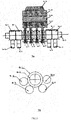
FIG.3 is a diagram showing the transmission of the feeding roller, wherein.3b is the right-side view of 3a. -
FIG.4 is a structural view of the combined feeding roller. -
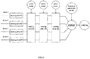
FIG.5 is a diagram of a spinning control system with four components asynchronous fed and carded -
FIG.6 is a diagram of a control model of a rotor spinning yarn system with four components asynchronous input.- 1-1, 1-2, 1-3: carding roller; 1-4, 1-5: trash ejection port; 1-6: feeding roller; 1-7: sliver; 1-8: compression spring; 1-9: feeding plate; 1-10: fiber transport channel; 1-11: navel; 1-12: rotor; 1-13: degassing hole; 1-14, 1-15: guide roller, 1-16: yarn;
- 2-5, 2-6, 2-7, 2-8: feeding roller; 2-1, 2-2, 2-3, 2-4: sliver; 2-9: feeding plate; 2-10, 2-11, 2-12: carding roller; 2-13: fiber flow; 2-14: rotor; 2-15: yarn;
- 3a-5, 3a-6, 3a-7, 3a-8: rollers; 3a-1, 3a-2, 3a-12, 3a-13: gears; 3a-3, 3a-4, 3a-9, 3a-10: idler gear; 3a-11: roller shaft; 3a-14, 3a-15, 3a-16: carding roller, 3a-17: spun yarn, 3b-1: gear; 3b-2: roller; 3b-3, 3b-4, 3b-5, 3b-6: gears;
- 4-1, 4-2, 4-3, 4-4: rollers; 4-5, 4-6, 4-12, 4-15: gears; 4-7, 4-11, 4-14: key; 4-8: fixed shaft sleeve; 4-9: screw; 4-10: bearing; 4-13: shaft. Four movable rollers (4-1, 4-2, 4-3, 4-4) are driven by the gears (4-5, 4-6, 4-12, 4-15) respectively.
- The meaning of the formula used in the text:
- V01: linear velocity of the feeding
roller 1; V02: linear velocity of the feedingroller 2; V03: linear velocity of the feedingroller 3; V04: linear velocity of the feedingroller 4; V1: the linear velocity of the cardingroller 1; V2: the linear velocity of the cardingroller 2; V3: the linear velocity of the cardingroller 3; V4: the linear speed of the rotor; V5: the linear velocity of the guide roller. - ρ1: linear density of sliver A (g / m)
- ρ2: linear density of sliver B (g / m)
- ρ3: linear density of sliver C (g / m)
- ρ4: linear density of sliver D (g / m)
- ρ: yarn density (g / m);
- ρ11: linear density of the sliver A passing through the carding roller 1 (g / m)
- ρ12: linear density of the sliver A passing through the carding roller 2 (g / m)
- ρ13: linear density of the sliver A passing through the carding roller 3 (g / m)
- ρ14: linear density of the sliver A in the rotor (g / m)
- ρ21: linear density of the sliver B passing through the carding roller 1 (g / m)
- ρ22: linear density of the sliver B passing through the carding roller 2 (g / m)
- ρ23: linear density of the sliver B passing through the carding roller 3 (g / m)
- ρ24: linear density of the sliver B in the rotor (g / m)
- ρ31: linear density of the sliver C passing through the carding roller 1 (g / m)
- ρ32: linear density of the sliver C passing through the carding roller 2 (g / m)
- ρ33: linear density of the sliver C passing through the carding roller 3 (g / m)
- ρ34: sliver C linear density in the rotor (g / m)
- ρ41: linear density of the sliver D passing through the carding roller 1 (g / m)
- ρ42: linear density of the sliver D passing through the carding roller 2 (g / m)
- ρ43: linear density of the sliver D passing through the carding roller 3 (g / m)
- ρ44: linear density of the sliver D in the rotor (g / m)
- E1: draft ratio of the carding
roller 1 to the feeding roller; - E2: draft ratio of the carding
roller 2 to the cardingroller 1; - E3: draft ratio of the carding
roller 3 to the cardingroller 2; - E4: draft ratio of the rotor to the carding
roller 3; - E5: draft ratio of the guide roller to the rotor;
- E: The total draft ratio of rotor spinning, which is equal to the draft ratio of the guide roller to the feeding roller.
-
Subscripts - As to feeding a plurality of the slivers, when the feeding speeds of feeding rollers are greatly different, the fiber holding time of each component is also greatly different. In the rotor spinning with single carding roller, due to the need of balancing the stripping /carding fibers, as well as the requirement of the fiber speed when transferring to the fiber transport channel, the rotation speed of the single carding roller is high. Therefore, when there is a significant difference in feeding amount, the number of times that a fiber of the four slivers is carded will be significantly different, and the more the fiber experiences carding, the larger will be the damage to this fiber.
- In order to solve the problem of the rotation speed of the carding roller against the damage to fiber and the even mixture of fibers, the present invention adopts the form of three-level carding rollers, that is, the first carding roller, the second carding roller and the third carding roller. The rotation speed of the first carding roller (ω = 1500-3000rpm) is relatively low, the needle density is relatively low, the working angle of the needle is relatively small. It is mainly configured for stripping, opening, cleaning and carding and focusing on making the total carding number of fibers of each sliver within a reasonable range, thereby reducing damage to the fiber. The speed of the second carding roller (ω = 3000-6000rpm) is mainly configured for stripping, carding and transferring fibers, wherein the needle density is also larger than the needle density of the first carding roller, and the working angle of the needle is relatively larger than that of the first carding roller. After being carded by the second carding roller, the longitudinal orientation of the fiber is optimized, and horizontal transfer mixing of the fiber is further optimized. The third carding roller is a high-speed carding roller (ω =6000-12000 rpm), which is mainly configured for stripping, carding and separating, and transferring fibers, wherein the needle density is larger than the needle density of the second carding roller, and the working angle of the needle is largest. Fibers passing through the third carding roller gets better carding and transfer. Furthermore, due to the high speed of the third carding roller, under the action of centrifugal force and air flow, a highly separated and continuous fiber flow passes through the fiber transport channel and enters orderly into the rotor to form yarns.
- Through the stripping, opening, cleaning, carding, and transfer of the three-level carding roller, the large-scale drafting function, where the slivers are combed into web, which is then combed into fiber bundles, which are separated into single fibers, is successful completed, which enhances the function of the carding area of the rotor spinning, meets the special requirements for the carding of multiple slivers asynchronously feeding into the rotor spun unit. The effects of flexibility, high efficiency, and high yield are realized.
-


-

- The blending ratios of components A, B, C, D in the rotor spinning yarn are K1, K2, K3, and K4 respectively:


- Assuming that the speed V5 of the guide roller is invariable, the variables of feeding speed V01, V02, V03, and V04 of the four slivers are respectively as follows:





- Assuming that: ρ1 = ρ2 = ρ3 = ρ4 = ρ0


- By changing V01, V02, V03, and V04, the blending ratio (color mixing ratio) of different fibers (different colors) in the yarn can be changed under the condition that V0 is kept invariable, so that k1, k2, k3, and k4 are changed between 0 - 100%. In various color mixing modes of four primary colors, the minimum increment of the color mixing ratio is 0.1, wherein one of the color schemes is as follows:
Table 1 color scheme color A color mixing ratio k1 color B color mixing ratio k2 color C color mixing ratio k3 color D color mixing ratio k4 Color code Monochromatic color A 1 0 0 0 1 color B 0 1 0 0 2 color C 0 0 1 0 3 color D 0 0 0 1 4 AB 0.1 0.9 0 0 5 0.2 0.8 0 0 6 0.3 0.7 0 0 7 0.4 0.6 0 0 8 0.5 0.5 0 0 9 0.6 0.4 0 0 10 0.7 0.3 0 0 11 0.8 0.2 0 0 12 0.9 0.1 0 0 13 AC 0.1 0 0.9 0 14 0.2 0 0.8 0 15 0.3 0 0.7 0 16 Double-color 0.4 0 0.6 0 17 mixing 0.5 0 0.5 18 0.6 0 0.4 0 19 0.7 0 0.3 0 20 0.8 0 0.2 0 21 0.9 0 0.1 0 22 AD 0.1 0 0 0.9 23 0.2 0 0 0.8 24 0.3 0 0 0.7 25 0.4 0 0 0.6 26 0.5 0 0 0.5 27 0.6 0 0 0.4 28 0.7 0 0 0.3 29 0.8 0 0 0.2 30 0.9 0 0 0.1 31 BC 0 0.1 0.9 0 32 0 0.2 0.8 0 33 0 0.3 0.7 0 34 0 0.4 0.6 0 35 0 0.5 0.5 0 36 0 0.6 0.4 0 37 0 0.7 0.3 0 38 0 0.8 0.2 0 39 0 0.9 0.1 0 40 BD 0 0. 1 0 0.9 41 0 0.2 0 0.8 42 0 0.3 0 0.7 43 0 0.4 0 0.6 44 0 0.5 0 0.5 45 0 0.6 0 0.4 46 0 0.7 0 0.3 47 0 0.8 0 0.2 48 0 0.9 0 0.1 49 CD 0 0 0.1 0.9 50 0 0 0.2 0.8 51 0 0 0.3 0.7 52 0 0 0.4 0.6 53 0 0 0.5 0.5 54 0 0 0.6 0.4 55 0 0 0.7 0.3 56 0 0 0.8 0.2 57 0 0 0.9 0.1 58 0.1 0.1 0.8 0 59 0.1 0.2 0.7 0 60 0.1 0.3 0.6 0 61 0.1 0.4 0.5 0 62 0.1 0.5 0.4 0 63 0.1 0.6 0.3 0 64 0.1 0.7 0.2 0 65 0.1 0.8 0.1 0 66 0.2 0.1 0.7 0 67 0.2 0.2 0.6 0 68 0.2 0.3 0.5 0 69 Tricolor mixing ABC 0.2 0.4 0.4 0 70 0.2 0.5 0.3 0 71 0.2 0.6 0.2 0 72 0.2 0.7 0.1 0 73 0.3 0.1 0.6 0 74 0.3 0.2 0.5 0 75 0.3 0.3 0.4 0 76 0.3 0.4 0.3 0 77 0.3 0.5 0.2 0 78 0.3 0.6 0.1 0 79 0.4 0.1 0.5 0 80 0.4 0.2 0.4 0 81 0.4 0.3 0.3 0 82 0.4 0.4 0.2 0 83 0.4 0.5 0.1 0 84 0.5 0.1 0.4 0 85 0.5 0.2 0.3 0 86 0.5 0.3 0.2 0 87 0.5 0.4 0.1 0 88 0.6 0.1 0.3 0 89 0.6 0.2 0.2 0 90 0.6 0.3 0.1 0 91 0.7 0.1 0.2 0 92 0.7 0.2 0.1 0 93 0.8 0.1 0.1 0 94 0 0.1 0.1 0.8 95 0 0.1 0.2 0.7 96 0 0.1 0.3 0.6 97 0 0.1 0.4 0.5 98 0 0.1 0.5 0.4 99 0 0.1 0.6 0.3 100 BCD 0 0.1 0.7 0.2 101 0 0.1 0.8 0.1 102 0 0.2 0.1 0.7 103 0 0.2 0.2 0.6 104 0 0.2 0.3 0.5 105 0 0.2 0.4 0.4 106 0 0.2 0.5 0.3 107 0 0.2 0.6 0.2 108 0 0.2 0.7 0.1 109 0 0.3 0.1 0.6 110 0 0.3 0.2 0.5 111 0 0.3 0.3 0.4 112 0 0.3 0.4 0.3 113 0 0.3 0.5 0.2 114 0 0.3 0.6 0.1 115 0 0.4 0.1 0.5 116 0 0.4 0.2 0.4 117 0 0.4 0.3 0.3 118 0 0.4 0.4 0.2 119 0 0.4 0.5 0.1 120 0 0.5 0.1 0.4 121 0 0.5 0.2 0.3 122 0 0.5 0.3 0.2 123 0 0.5 0.4 0.1 124 0 0.6 0.1 0.3 125 0 0.6 0.2 0.2 126 0 0.6 0.3 0.1 127 0 0.7 0.1 0.2 128 0 0.7 0.2 0.1 129 0 0.8 0.1 0.1 130 CDA 0.8 0 0.1 0.1 131 0.7 0 0.1 0.2 132 0.6 0 0.1 0.3 133 0.5 0 0.1 0.4 134 0.4 0 0.1 0.5 135 0.3 0 0.1 0.6 136 0.2 0 0.1 0.7 137 0.1 0 0.1 0.8 138 0.7 0 0.2 0.1 139 0.6 0 0.2 0.2 140 0.5 0 0.2 0.3 141 0.4 0 0.2 0.4 142 0.3 0 0.2 0.5 143 0.2 0 0.2 0.6 144 0.1 0 0.2 0.7 145 0.6 0 0.3 0.1 146 0.5 0 0.3 0.2 157 0.4 0 0.3 0.3 148 0.3 0 0.3 0.4 149 0.2 0 0.3 0.5 150 0.1 0 0.3 0.6 151 0.5 0 0.4 0.1 152 0.4 0 0.4 0.2 153 0.3 0 0.4 0.3 154 0.2 0 0.4 0.4 155 0.1 0 0.4 0.5 156 0.4 0 0.5 0.1 157 0.3 0 0.5 0.2 158 0.2 0 0.5 0.3 159 0.1 0 0.5 0.4 160 0.3 0 0.6 0.1 161 0.2 0 0.6 0.2 162 0.1 0 0.6 0.3 163 0.2 0 0.7 0.1 164 0.1 0 0.7 0.2 165 0.1 0 0.8 0.1 166 0.1 0.1 0.1 0.7 167 0.1 0.1 0.2 0.6 168 0.1 0.1 0.3 0.5 169 0.1 0.1 0.4 0.4 170 0.1 0.1 0.5 0.3 171 0.1 0.1 0.6 0.2 172 0.1 0.1 0.7 0.1 173 0.1 0.1 0.7 0.1 174 0.1 0.2 0.6 0.1 175 Four-color ABCD 0.1 0.3 0.5 0.1 176 mixing 0.1 0.4 0.4 0.1 177 0.1 0.5 0.3 0.1 178 0.1 0.6 0.2 0.1 179 0.1 0.7 0.1 0.1 180 0.1 0.7 0.1 0.1 181 0.1 0.6 0.1 0.2 182 0.1 0.5 0.1 0.3 183 0.1 0.4 0.1 0.4 184 0.1 0.3 0.1 0.5 185 0.1 0.2 0.1 0.6 186 0.1 0.1 0.1 0.7 187 0.2 0.1 0.1 0.6 188 0.2 0.1 0.2 0.5 189 0.2 0.1 0.3 0.4 190 0.2 0.1 0.4 0.3 191 0.2 0.1 0.5 0.2 192 0.2 0.1 0.6 0.1 193 0.2 0.1 0.6 0.1 194 0.2 0.2 0.5 0.1 195 0.2 0.3 0.4 0.1 196 0.2 0.4 0.3 0.1 197 0.2 0.5 0.2 0.1 198 0.2 0.6 0.1 0.1 199 0.2 0.6 0.1 0.1 200 0.2 0.5 0.1 0.2 201 0.2 0.4 0.1 0.3 202 0.2 0.3 0.1 0.4 203 0.2 0.2 0.1 0.5 204 0.2 0.1 0.1 0.6 205 0.3 0.1 0.1 0.5 206 0.3 0.1 0.2 0.4 207 0.3 0.1 0.3 0.3 208 0.3 0.1 0.4 0.2 209 0.3 0.1 0.5 0.1 210 0.3 0. 1 0.5 0.1 211 0.3 0.2 0.4 0.1 212 0.3 0.3 0.3 0.1 213 0.3 0.4 0.2 0.1 214 0.3 0.5 0.1 0.1 215 0.3 0.5 0.1 0.1 216 0.3 0.4 0.1 0.2 217 0.3 0.3 0.1 0.3 218 0.3 0.2 0.1 0.4 219 0.3 0.1 0.1 0.5 220 0.4 0.1 0.1 0.4 221 0.4 0.1 0.2 0.3 222 0.4 0.1 0.3 0.2 223 0.4 0.1 0.4 0.1 224 0.4 0.1 0.4 0.1 225 0.4 0.2 0.3 0.1 226 0.4 0.3 0.2 0.1 227 0.4 0.4 0.1 0.1 228 0.4 0.4 0.1 0.1 229 0.4 0.3 0.1 0.2 230 0.4 0.2 0.1 0.3 231 0.4 0.1 0.1 0.4 232 0.5 0.1 0.1 0.3 233 0.5 0.1 0.2 0.2 234 0.5 0.1 0.3 0.1 235 0.5 0.1 0.3 0.1 236 0.5 0.2 0.2 0.1 237 0.5 0.3 0.1 0.1 238 0.5 0.3 0.1 0.1 239 0.5 0.2 0.1 0.2 240 0.5 0.1 0.1 0.3 241 0.6 0.1 0.1 0.2 242 0.6 0.1 0.2 0.1 243 0.6 0.1 0.2 0.1 244 0.6 0.2 0.1 0.1 245 0.6 0.2 0.1 0.1 246 0.6 0.1 0.1 0.2 247 0.7 0.1 0.1 0.1 248 Note: k1+k2+k3+k4= 100% can have numerous combinations. Based on the four primary colors (four kinds of color slivers) by coupling and drafting, color alternating, gradient color matching, twisting and mixture, numerous color schemes can be formed. In addition, it is possible to form a segment-color yarn having a variety of color distribution in the yarn. - The dynamic change rate of density of the rotor spun yarn is shown as below:


- Then,

- From the absolute increment of the linear density and relative increment of the linear density, it can be found that, the linear density change of the yarn, which totally depends on the V01+ΔV01, V02+ΔV02, V03+ΔV03, V04+ΔV04, can have 9 different patterns. Therefore, there can be 9 kinds of yarn in different forms.
- ① A yarn with variable linear density, wherein one component of the yarn has variable linear density and three components of the yarn have invariable linear densities.


- ② A yarn with variable linear density, wherein two components having variable linear densities and two components having invariable linear densities.




- ③ A yarn with variable linear density, wherein three components having variable linear densities and one component having invariable linear density.



- ④ A yarn with variable linear density, wherein four components having variable linear densities.

- ⑤ A yarn with variable linear density, wherein one component of the yarn is continuous and three components of the yarn are discontinuous.




- ⑥ A yarn with variable linear density, wherein two components of the yarn are continuous and two components of the yarn are discontinuous.


- ⑦ A yarn with variable linear density, wherein three component of the yarn are continuous and one component of the yarn is discontinuous.


- ⑧ A yarn with variable linear density, wherein four components of the yarn are continuous and have variable linear densities.

- ⑨ The method of dynamic feed speed control of spun yarn Because


Claims (12)
- A rotor spinning method for four-sliver asynchronous inputting and three-level carding, characterized in that:1) feeding fiber by combined feeding rollers with four rotational freedom degrees into carding area where a three-level carding roller is used for carding;2) moving the combined feeding rollers 1, 2, 3, 4 at linear speeds V01, V02, V03, V04, respectively; moving a rotor at a linear speed V4 and moving a guide roller at a linear speed V5; setting linear densities of four slivers drafted by four rollers to be ρ1, ρ2, ρ3, and ρ4, respectively, and setting a rotor spun yarn density to be ρ, such that a draft ratio of a rotor spinning yarn is as below:

 3) blending ratios of four slivers in the rotor spinning yarn are K1, K2, K3, and K4, respectively:


 4) assuming that the speed V5 of the guide roller is invariable, the variables of feeding speeds V01, V02, V03, V04 of the feeding rollers of the four slivers are respectively as follows: V01' = V01 + ΔV01, V02' = V02 + ΔV02, V03' = V03 + ΔV03, V04' = V04 + ΔV04,, then the dynamic linear density of the rotor spun yarn is obtained according to formula (2)
 5) assuming that ρ1 = ρ2 = ρ3 = ρ4 = ρ0, V01+V02+V03+V04 = V0, obtaining a reference blending ratio according to the formulas (3), (4), (5), (6) as


- The method according to claim 1, characterized in that: assuming that ρ1 = ρ2 = ρ3 = ρ4 = ρ0, V01 + V02 + V03 + V04 = V0, obtaining a dynamic change rate of the rotor spun yarn density according to formulas (2) and (7):

- The method according to claim 2, characterized in that:




- The method according to claim 2, characterized in that:




- The method according to claim 2, characterized in that:


- The method according to claim 2, characterized in that:

- The method according to claim 2, characterized in that:



- The method according to claim 2, characterized in that:


- The method according to claim 2, characterized in that:


- The method according to claim 2, characterized in that: in control method of dynamic feeding speed of the yarn, ΔV0 = ΔV01 + ΔV02 + ΔV03 + ΔV04, change of the speed is derived from ΔV01, ΔV02, ΔV03, or ΔV04 and determined by the blending ratio, and then ΔV01 = K'1(V0+ΔV)-V01, ΔV02 = K'2(V0+ΔV)-V02, ΔV03 = K'3(V0+ΔV)-V03, ΔV04 = K'4(V0+ΔV)-V04.
- A device for realizing the method according to any one of the preceding claims, characterized in that, the device comprises a spinning system and a computer control system, the spinning system comprises a feeding and carding mechanism, a collecting and twisting mechanism, and a winding mechanism, characterized in that, the feeding and carding mechanism comprises combined feeding rollers having four rotational freedom degrees, a three-level carding roller; wherein a speed ratio of four rollers of the combined feeding rollers with four rotational freedom degrees can be adjusted, the collecting and twisting mechanism includes a fiber transport channel, a rotor, and a guide device; the winding mechanism includes a guide and winding mechanism; the computer control system includes a PLC programmable controller, a servo driver, a servo motor; wherein the combined feeding rollers with four rotational freedom degrees and the three-level carding roller are driven by the servo motor.
- The device according to claim 10, characterized in that the combined feeding rollers having four rotational freedom degrees comprises a shaft, a bearing, a hollow shaft, a first gear, a second gear, a third gear, a fourth gear, a washer, a first movable roller, a second movable roller, a third movable roller, and a fourth movable roller, wherein the first gear, the second gear, the third gear, and the fourth gear, the first movable roller, the second movable roller, the third movable roller, and the fourth movable roller rotate around the same axis, the first gear, the second gear, the third gear, and the fourth gear drive the first movable roller, the second movable roller, the third movable roller, and the fourth movable roller, respectively.
Applications Claiming Priority (2)
| Application Number | Priority Date | Filing Date | Title |
|---|---|---|---|
| CN201510521070.6A CN105040194B (en) | 2015-08-21 | 2015-08-21 | The asynchronous input of four slivers and the revolving cup spinning method and device of three fractions comb |
| PCT/CN2015/000736 WO2017031611A1 (en) | 2015-08-21 | 2015-10-30 | Rotor spinning method and device for four-sliver asynchronous inputting and three-level carding |
Publications (3)
| Publication Number | Publication Date |
|---|---|
| EP3327184A1 true EP3327184A1 (en) | 2018-05-30 |
| EP3327184A4 EP3327184A4 (en) | 2018-09-05 |
| EP3327184B1 EP3327184B1 (en) | 2019-07-10 |
Family
ID=54447157
Family Applications (1)
| Application Number | Title | Priority Date | Filing Date |
|---|---|---|---|
| EP15901885.2A Not-in-force EP3327184B1 (en) | 2015-08-21 | 2015-10-30 | Rotor spinning method and device for four-sliver asynchronous inputting and three-level carding |
Country Status (3)
| Country | Link |
|---|---|
| EP (1) | EP3327184B1 (en) |
| CN (1) | CN105040194B (en) |
| WO (1) | WO2017031611A1 (en) |
Families Citing this family (6)
| Publication number | Priority date | Publication date | Assignee | Title |
|---|---|---|---|---|
| CN106087130B (en) * | 2016-08-01 | 2018-10-23 | 东华大学 | A kind of color matching method of colored fibre |
| CN108588932A (en) * | 2018-04-27 | 2018-09-28 | 江南大学 | Change the filament short-fiber composite yarn process units of blended when fineness of yarn online |
| CN108588931A (en) * | 2018-04-27 | 2018-09-28 | 江南大学 | Change the filament short-fiber composite yarn production method of blended when fineness of yarn online |
| CN108560095A (en) * | 2018-04-27 | 2018-09-21 | 江南大学 | The production technology of self-loopa multiple clips Revolving cup spinning colour mixture slub |
| CN108588938A (en) * | 2018-05-08 | 2018-09-28 | 江南大学 | Polynary primary colours fiber is uniformly mixed into the production technology of yarn |
| CN114000236A (en) * | 2021-11-12 | 2022-02-01 | 张家港市光明毛纺织有限公司 | Production method of colored straight-strip wool-spraying fancy yarn |
Family Cites Families (13)
| Publication number | Priority date | Publication date | Assignee | Title |
|---|---|---|---|---|
| DE4039773C2 (en) * | 1990-01-23 | 2003-06-26 | Truetzschler Gmbh & Co Kg | Cotton opening and cleaning machine - has equal size cylinders and trash extn. in stages |
| JP3334075B2 (en) * | 1998-09-02 | 2002-10-15 | 日清紡績株式会社 | Method for producing composite yarn and composite yarn thereof |
| DE10215453A1 (en) * | 2002-04-09 | 2003-10-23 | Rieter Ingolstadt Spinnerei | Feed roller and opening device for a spinning device |
| CZ300469B6 (en) * | 2004-02-16 | 2009-05-27 | Oerlikon Czech S.R.O. | Method for feeding sliver when producing fancy yarn and spinning unit for making the same |
| CN102277662A (en) * | 2011-07-05 | 2011-12-14 | 嘉兴学院 | Method and device for drawing sectional colored cotton or sectional colored wool slivers with uniform linear intensity |
| CN103556320B (en) * | 2013-07-18 | 2016-10-05 | 嘉兴学院 | The device and method of blending and color mixing is realized based on three rove coupling draw twisting systems |
| CN103911697B (en) * | 2014-03-24 | 2016-08-17 | 东华大学 | A kind of pair is fed for carding agencies |
| CN103938322B (en) * | 2014-04-25 | 2017-03-15 | 嘉兴学院 | A kind of Revolving cup spinning colour mixture resultant yarn method and device and product |
| CN203846185U (en) * | 2014-04-25 | 2014-09-24 | 嘉兴学院 | Color mixing and yarn forming device for rotor spinning |
| CN104711720B (en) * | 2015-03-27 | 2017-03-01 | 江南大学 | The three component similarities and differences walk the method and device that two grades of drawing-offs spin many color bunchy yarns |
| CN104762713B (en) * | 2015-03-27 | 2018-10-30 | 江南大学 | The three component similarities and differences walk the method and device of drawing-off regulation and control yarn linear density and blending ratio |
| CN104726990B (en) * | 2015-03-27 | 2019-02-01 | 江南大学 | The method and device of mixed colour-spun yarns is realized based on the coupling drawing-off of CMYK four primary rove |
| CN205133851U (en) * | 2015-08-21 | 2016-04-06 | 江南大学 | Four silver asynchronous input and tertiary rotor spinning spinning device who divides comb |
-
2015
- 2015-08-21 CN CN201510521070.6A patent/CN105040194B/en active Active
- 2015-10-30 WO PCT/CN2015/000736 patent/WO2017031611A1/en not_active Ceased
- 2015-10-30 EP EP15901885.2A patent/EP3327184B1/en not_active Not-in-force
Also Published As
| Publication number | Publication date |
|---|---|
| EP3327184A4 (en) | 2018-09-05 |
| WO2017031611A1 (en) | 2017-03-02 |
| EP3327184B1 (en) | 2019-07-10 |
| CN105040194A (en) | 2015-11-11 |
| CN105040194B (en) | 2018-01-16 |
Similar Documents
| Publication | Publication Date | Title |
|---|---|---|
| EP3327185B1 (en) | Rotor spinning method and apparatus using three-cotton-sliver asynchronous input and multi-stage carding | |
| EP3327184B1 (en) | Rotor spinning method and device for four-sliver asynchronous inputting and three-level carding | |
| EP3327186B1 (en) | Rotor spinning method and apparatus using two-cotton-sliver asynchronous input and three-stage carding | |
| CN203846172U (en) | Drafting and twisting device with three rough yarns drafting independently and twisting simultaneously | |
| CN102031600B (en) | Ring spinning method and device of equi-linear density space dyed yarn | |
| CN104711720B (en) | The three component similarities and differences walk the method and device that two grades of drawing-offs spin many color bunchy yarns | |
| CN203846185U (en) | Color mixing and yarn forming device for rotor spinning | |
| CN103938322A (en) | Rotor spinning melange yarn forming method and device and product | |
| JP2016535177A (en) | Apparatus and method for realizing blending and color mixing based on a triple roving coupling drawing twisted yarn system, and color yarn made by the method | |
| EP3327183B1 (en) | Rotor spinning method and device for five-sliver asynchronous inputting and three-level carding | |
| CN104762713B (en) | The three component similarities and differences walk the method and device of drawing-off regulation and control yarn linear density and blending ratio | |
| CN104726977B (en) | The five component similarities and differences walk two level drawing-off and spin colorful ring or point point yarn method | |
| CN104762714A (en) | Yarn method and device for implementing color mixing of double-color roving through asynchronous/synchronous two-stage drafting | |
| CN204198955U (en) | A kind of drawing frame producing polychrome section coloured yarn | |
| CN104790074A (en) | Method and device for five-component asynchronous and synchronous drafting regulation and control of yarn linear density and blended ratio | |
| CN109750400A (en) | Alternating draft three-channel spinning device and spinning method of variable count variable ratio variable twist yarn | |
| CN205133850U (en) | Two silver asynchronous input and tertiary rotor spinning spinning device who divides comb | |
| CN104726975B (en) | The method that the step two level drawing-off of the four component similarities and differences spins colorful slub | |
| CN205133853U (en) | Three silver asynchronous input and tertiary rotor spinning spinning device who divides comb | |
| WO2016155165A1 (en) | Method and device for dynamically allocating linear density and blending ratio of yarn through five-component asynchronous drafting | |
| CN204530071U (en) | Three component similarities and differences step secondary drawing-off spinning apparatus | |
| CN205133852U (en) | Five silver asynchronous input and tertiary rotor spinning spinning device who divides comb | |
| CN205133851U (en) | Four silver asynchronous input and tertiary rotor spinning spinning device who divides comb | |
| CN204530069U (en) | Four component similarities and differences step secondary drawing-off spinning apparatus | |
| CN210104151U (en) | Alternating draft four-channel spinning device |
Legal Events
| Date | Code | Title | Description |
|---|---|---|---|
| STAA | Information on the status of an ep patent application or granted ep patent |
Free format text: STATUS: THE INTERNATIONAL PUBLICATION HAS BEEN MADE |
|
| PUAI | Public reference made under article 153(3) epc to a published international application that has entered the european phase |
Free format text: ORIGINAL CODE: 0009012 |
|
| STAA | Information on the status of an ep patent application or granted ep patent |
Free format text: STATUS: REQUEST FOR EXAMINATION WAS MADE |
|
| 17P | Request for examination filed |
Effective date: 20180222 |
|
| AK | Designated contracting states |
Kind code of ref document: A1 Designated state(s): AL AT BE BG CH CY CZ DE DK EE ES FI FR GB GR HR HU IE IS IT LI LT LU LV MC MK MT NL NO PL PT RO RS SE SI SK SM TR |
|
| AX | Request for extension of the european patent |
Extension state: BA ME |
|
| A4 | Supplementary search report drawn up and despatched |
Effective date: 20180807 |
|
| RIC1 | Information provided on ipc code assigned before grant |
Ipc: D01H 4/32 20060101ALI20180801BHEP Ipc: D01H 4/08 20060101AFI20180801BHEP Ipc: D01H 4/44 20060101ALI20180801BHEP |
|
| DAV | Request for validation of the european patent (deleted) | ||
| DAX | Request for extension of the european patent (deleted) | ||
| GRAP | Despatch of communication of intention to grant a patent |
Free format text: ORIGINAL CODE: EPIDOSNIGR1 |
|
| STAA | Information on the status of an ep patent application or granted ep patent |
Free format text: STATUS: GRANT OF PATENT IS INTENDED |
|
| INTG | Intention to grant announced |
Effective date: 20190424 |
|
| GRAS | Grant fee paid |
Free format text: ORIGINAL CODE: EPIDOSNIGR3 |
|
| GRAA | (expected) grant |
Free format text: ORIGINAL CODE: 0009210 |
|
| STAA | Information on the status of an ep patent application or granted ep patent |
Free format text: STATUS: THE PATENT HAS BEEN GRANTED |
|
| AK | Designated contracting states |
Kind code of ref document: B1 Designated state(s): AL AT BE BG CH CY CZ DE DK EE ES FI FR GB GR HR HU IE IS IT LI LT LU LV MC MK MT NL NO PL PT RO RS SE SI SK SM TR |
|
| REG | Reference to a national code |
Ref country code: GB Ref legal event code: FG4D |
|
| REG | Reference to a national code |
Ref country code: CH Ref legal event code: EP Ref country code: AT Ref legal event code: REF Ref document number: 1153670 Country of ref document: AT Kind code of ref document: T Effective date: 20190715 |
|
| REG | Reference to a national code |
Ref country code: IE Ref legal event code: FG4D |
|
| REG | Reference to a national code |
Ref country code: DE Ref legal event code: R096 Ref document number: 602015033781 Country of ref document: DE |
|
| REG | Reference to a national code |
Ref country code: NL Ref legal event code: MP Effective date: 20190710 |
|
| REG | Reference to a national code |
Ref country code: LT Ref legal event code: MG4D |
|
| REG | Reference to a national code |
Ref country code: AT Ref legal event code: MK05 Ref document number: 1153670 Country of ref document: AT Kind code of ref document: T Effective date: 20190710 |
|
| PG25 | Lapsed in a contracting state [announced via postgrant information from national office to epo] |
Ref country code: SE Free format text: LAPSE BECAUSE OF FAILURE TO SUBMIT A TRANSLATION OF THE DESCRIPTION OR TO PAY THE FEE WITHIN THE PRESCRIBED TIME-LIMIT Effective date: 20190710 Ref country code: HR Free format text: LAPSE BECAUSE OF FAILURE TO SUBMIT A TRANSLATION OF THE DESCRIPTION OR TO PAY THE FEE WITHIN THE PRESCRIBED TIME-LIMIT Effective date: 20190710 Ref country code: LT Free format text: LAPSE BECAUSE OF FAILURE TO SUBMIT A TRANSLATION OF THE DESCRIPTION OR TO PAY THE FEE WITHIN THE PRESCRIBED TIME-LIMIT Effective date: 20190710 Ref country code: NL Free format text: LAPSE BECAUSE OF FAILURE TO SUBMIT A TRANSLATION OF THE DESCRIPTION OR TO PAY THE FEE WITHIN THE PRESCRIBED TIME-LIMIT Effective date: 20190710 Ref country code: PT Free format text: LAPSE BECAUSE OF FAILURE TO SUBMIT A TRANSLATION OF THE DESCRIPTION OR TO PAY THE FEE WITHIN THE PRESCRIBED TIME-LIMIT Effective date: 20191111 Ref country code: FI Free format text: LAPSE BECAUSE OF FAILURE TO SUBMIT A TRANSLATION OF THE DESCRIPTION OR TO PAY THE FEE WITHIN THE PRESCRIBED TIME-LIMIT Effective date: 20190710 Ref country code: NO Free format text: LAPSE BECAUSE OF FAILURE TO SUBMIT A TRANSLATION OF THE DESCRIPTION OR TO PAY THE FEE WITHIN THE PRESCRIBED TIME-LIMIT Effective date: 20191010 Ref country code: BG Free format text: LAPSE BECAUSE OF FAILURE TO SUBMIT A TRANSLATION OF THE DESCRIPTION OR TO PAY THE FEE WITHIN THE PRESCRIBED TIME-LIMIT Effective date: 20191010 Ref country code: AT Free format text: LAPSE BECAUSE OF FAILURE TO SUBMIT A TRANSLATION OF THE DESCRIPTION OR TO PAY THE FEE WITHIN THE PRESCRIBED TIME-LIMIT Effective date: 20190710 |
|
| PG25 | Lapsed in a contracting state [announced via postgrant information from national office to epo] |
Ref country code: AL Free format text: LAPSE BECAUSE OF FAILURE TO SUBMIT A TRANSLATION OF THE DESCRIPTION OR TO PAY THE FEE WITHIN THE PRESCRIBED TIME-LIMIT Effective date: 20190710 Ref country code: ES Free format text: LAPSE BECAUSE OF FAILURE TO SUBMIT A TRANSLATION OF THE DESCRIPTION OR TO PAY THE FEE WITHIN THE PRESCRIBED TIME-LIMIT Effective date: 20190710 Ref country code: IS Free format text: LAPSE BECAUSE OF FAILURE TO SUBMIT A TRANSLATION OF THE DESCRIPTION OR TO PAY THE FEE WITHIN THE PRESCRIBED TIME-LIMIT Effective date: 20191110 Ref country code: LV Free format text: LAPSE BECAUSE OF FAILURE TO SUBMIT A TRANSLATION OF THE DESCRIPTION OR TO PAY THE FEE WITHIN THE PRESCRIBED TIME-LIMIT Effective date: 20190710 Ref country code: GR Free format text: LAPSE BECAUSE OF FAILURE TO SUBMIT A TRANSLATION OF THE DESCRIPTION OR TO PAY THE FEE WITHIN THE PRESCRIBED TIME-LIMIT Effective date: 20191011 Ref country code: RS Free format text: LAPSE BECAUSE OF FAILURE TO SUBMIT A TRANSLATION OF THE DESCRIPTION OR TO PAY THE FEE WITHIN THE PRESCRIBED TIME-LIMIT Effective date: 20190710 |
|
| PG25 | Lapsed in a contracting state [announced via postgrant information from national office to epo] |
Ref country code: TR Free format text: LAPSE BECAUSE OF FAILURE TO SUBMIT A TRANSLATION OF THE DESCRIPTION OR TO PAY THE FEE WITHIN THE PRESCRIBED TIME-LIMIT Effective date: 20190710 |
|
| PG25 | Lapsed in a contracting state [announced via postgrant information from national office to epo] |
Ref country code: IT Free format text: LAPSE BECAUSE OF FAILURE TO SUBMIT A TRANSLATION OF THE DESCRIPTION OR TO PAY THE FEE WITHIN THE PRESCRIBED TIME-LIMIT Effective date: 20190710 Ref country code: RO Free format text: LAPSE BECAUSE OF FAILURE TO SUBMIT A TRANSLATION OF THE DESCRIPTION OR TO PAY THE FEE WITHIN THE PRESCRIBED TIME-LIMIT Effective date: 20190710 Ref country code: DK Free format text: LAPSE BECAUSE OF FAILURE TO SUBMIT A TRANSLATION OF THE DESCRIPTION OR TO PAY THE FEE WITHIN THE PRESCRIBED TIME-LIMIT Effective date: 20190710 Ref country code: EE Free format text: LAPSE BECAUSE OF FAILURE TO SUBMIT A TRANSLATION OF THE DESCRIPTION OR TO PAY THE FEE WITHIN THE PRESCRIBED TIME-LIMIT Effective date: 20190710 Ref country code: PL Free format text: LAPSE BECAUSE OF FAILURE TO SUBMIT A TRANSLATION OF THE DESCRIPTION OR TO PAY THE FEE WITHIN THE PRESCRIBED TIME-LIMIT Effective date: 20190710 |
|
| PG25 | Lapsed in a contracting state [announced via postgrant information from national office to epo] |
Ref country code: MC Free format text: LAPSE BECAUSE OF FAILURE TO SUBMIT A TRANSLATION OF THE DESCRIPTION OR TO PAY THE FEE WITHIN THE PRESCRIBED TIME-LIMIT Effective date: 20190710 Ref country code: SK Free format text: LAPSE BECAUSE OF FAILURE TO SUBMIT A TRANSLATION OF THE DESCRIPTION OR TO PAY THE FEE WITHIN THE PRESCRIBED TIME-LIMIT Effective date: 20190710 Ref country code: IS Free format text: LAPSE BECAUSE OF FAILURE TO SUBMIT A TRANSLATION OF THE DESCRIPTION OR TO PAY THE FEE WITHIN THE PRESCRIBED TIME-LIMIT Effective date: 20200224 Ref country code: SM Free format text: LAPSE BECAUSE OF FAILURE TO SUBMIT A TRANSLATION OF THE DESCRIPTION OR TO PAY THE FEE WITHIN THE PRESCRIBED TIME-LIMIT Effective date: 20190710 Ref country code: CZ Free format text: LAPSE BECAUSE OF FAILURE TO SUBMIT A TRANSLATION OF THE DESCRIPTION OR TO PAY THE FEE WITHIN THE PRESCRIBED TIME-LIMIT Effective date: 20190710 |
|
| REG | Reference to a national code |
Ref country code: CH Ref legal event code: PL |
|
| REG | Reference to a national code |
Ref country code: DE Ref legal event code: R097 Ref document number: 602015033781 Country of ref document: DE |
|
| PLBE | No opposition filed within time limit |
Free format text: ORIGINAL CODE: 0009261 |
|
| STAA | Information on the status of an ep patent application or granted ep patent |
Free format text: STATUS: NO OPPOSITION FILED WITHIN TIME LIMIT |
|
| PG2D | Information on lapse in contracting state deleted |
Ref country code: IS |
|
| PG25 | Lapsed in a contracting state [announced via postgrant information from national office to epo] |
Ref country code: LI Free format text: LAPSE BECAUSE OF NON-PAYMENT OF DUE FEES Effective date: 20191031 Ref country code: LU Free format text: LAPSE BECAUSE OF NON-PAYMENT OF DUE FEES Effective date: 20191030 Ref country code: CH Free format text: LAPSE BECAUSE OF NON-PAYMENT OF DUE FEES Effective date: 20191031 |
|
| 26N | No opposition filed |
Effective date: 20200603 |
|
| REG | Reference to a national code |
Ref country code: BE Ref legal event code: MM Effective date: 20191031 |
|
| PG25 | Lapsed in a contracting state [announced via postgrant information from national office to epo] |
Ref country code: BE Free format text: LAPSE BECAUSE OF NON-PAYMENT OF DUE FEES Effective date: 20191031 Ref country code: SI Free format text: LAPSE BECAUSE OF FAILURE TO SUBMIT A TRANSLATION OF THE DESCRIPTION OR TO PAY THE FEE WITHIN THE PRESCRIBED TIME-LIMIT Effective date: 20190710 |
|
| GBPC | Gb: european patent ceased through non-payment of renewal fee |
Effective date: 20191030 |
|
| PG25 | Lapsed in a contracting state [announced via postgrant information from national office to epo] |
Ref country code: FR Free format text: LAPSE BECAUSE OF NON-PAYMENT OF DUE FEES Effective date: 20191031 Ref country code: GB Free format text: LAPSE BECAUSE OF NON-PAYMENT OF DUE FEES Effective date: 20191030 Ref country code: IE Free format text: LAPSE BECAUSE OF NON-PAYMENT OF DUE FEES Effective date: 20191030 |
|
| PGFP | Annual fee paid to national office [announced via postgrant information from national office to epo] |
Ref country code: DE Payment date: 20201026 Year of fee payment: 6 |
|
| PG25 | Lapsed in a contracting state [announced via postgrant information from national office to epo] |
Ref country code: CY Free format text: LAPSE BECAUSE OF FAILURE TO SUBMIT A TRANSLATION OF THE DESCRIPTION OR TO PAY THE FEE WITHIN THE PRESCRIBED TIME-LIMIT Effective date: 20190710 |
|
| PG25 | Lapsed in a contracting state [announced via postgrant information from national office to epo] |
Ref country code: MT Free format text: LAPSE BECAUSE OF FAILURE TO SUBMIT A TRANSLATION OF THE DESCRIPTION OR TO PAY THE FEE WITHIN THE PRESCRIBED TIME-LIMIT Effective date: 20190710 Ref country code: HU Free format text: LAPSE BECAUSE OF FAILURE TO SUBMIT A TRANSLATION OF THE DESCRIPTION OR TO PAY THE FEE WITHIN THE PRESCRIBED TIME-LIMIT; INVALID AB INITIO Effective date: 20151030 |
|
| REG | Reference to a national code |
Ref country code: DE Ref legal event code: R119 Ref document number: 602015033781 Country of ref document: DE |
|
| PG25 | Lapsed in a contracting state [announced via postgrant information from national office to epo] |
Ref country code: MK Free format text: LAPSE BECAUSE OF FAILURE TO SUBMIT A TRANSLATION OF THE DESCRIPTION OR TO PAY THE FEE WITHIN THE PRESCRIBED TIME-LIMIT Effective date: 20190710 |
|
| PG25 | Lapsed in a contracting state [announced via postgrant information from national office to epo] |
Ref country code: DE Free format text: LAPSE BECAUSE OF NON-PAYMENT OF DUE FEES Effective date: 20220503 |