EP3326830A1 - Printing plate, printed matter, and printing method - Google Patents
Printing plate, printed matter, and printing method Download PDFInfo
- Publication number
- EP3326830A1 EP3326830A1 EP16827618.6A EP16827618A EP3326830A1 EP 3326830 A1 EP3326830 A1 EP 3326830A1 EP 16827618 A EP16827618 A EP 16827618A EP 3326830 A1 EP3326830 A1 EP 3326830A1
- Authority
- EP
- European Patent Office
- Prior art keywords
- recessed area
- printed
- printing
- printing plate
- deposit
- Prior art date
- Legal status (The legal status is an assumption and is not a legal conclusion. Google has not performed a legal analysis and makes no representation as to the accuracy of the status listed.)
- Withdrawn
Links
Images



Classifications
-
- B—PERFORMING OPERATIONS; TRANSPORTING
- B41—PRINTING; LINING MACHINES; TYPEWRITERS; STAMPS
- B41M—PRINTING, DUPLICATING, MARKING, OR COPYING PROCESSES; COLOUR PRINTING
- B41M1/00—Inking and printing with a printer's forme
- B41M1/10—Intaglio printing ; Gravure printing
-
- B—PERFORMING OPERATIONS; TRANSPORTING
- B41—PRINTING; LINING MACHINES; TYPEWRITERS; STAMPS
- B41F—PRINTING MACHINES OR PRESSES
- B41F17/00—Printing apparatus or machines of special types or for particular purposes, not otherwise provided for
- B41F17/001—Pad printing apparatus or machines
-
- B—PERFORMING OPERATIONS; TRANSPORTING
- B41—PRINTING; LINING MACHINES; TYPEWRITERS; STAMPS
- B41M—PRINTING, DUPLICATING, MARKING, OR COPYING PROCESSES; COLOUR PRINTING
- B41M1/00—Inking and printing with a printer's forme
-
- B—PERFORMING OPERATIONS; TRANSPORTING
- B41—PRINTING; LINING MACHINES; TYPEWRITERS; STAMPS
- B41M—PRINTING, DUPLICATING, MARKING, OR COPYING PROCESSES; COLOUR PRINTING
- B41M5/00—Duplicating or marking methods; Sheet materials for use therein
- B41M5/025—Duplicating or marking methods; Sheet materials for use therein by transferring ink from the master sheet
- B41M5/03—Duplicating or marking methods; Sheet materials for use therein by transferring ink from the master sheet by pressure
-
- B—PERFORMING OPERATIONS; TRANSPORTING
- B41—PRINTING; LINING MACHINES; TYPEWRITERS; STAMPS
- B41N—PRINTING PLATES OR FOILS; MATERIALS FOR SURFACES USED IN PRINTING MACHINES FOR PRINTING, INKING, DAMPING, OR THE LIKE; PREPARING SUCH SURFACES FOR USE AND CONSERVING THEM
- B41N1/00—Printing plates or foils; Materials therefor
- B41N1/04—Printing plates or foils; Materials therefor metallic
- B41N1/06—Printing plates or foils; Materials therefor metallic for relief printing or intaglio printing
-
- B—PERFORMING OPERATIONS; TRANSPORTING
- B41—PRINTING; LINING MACHINES; TYPEWRITERS; STAMPS
- B41C—PROCESSES FOR THE MANUFACTURE OR REPRODUCTION OF PRINTING SURFACES
- B41C1/00—Forme preparation
- B41C1/02—Engraving; Heads therefor
- B41C1/025—Engraving; Heads therefor characterised by means for the liquid etching of substrates for the manufacturing of relief or intaglio printing forms, already provided with resist pattern
-
- B—PERFORMING OPERATIONS; TRANSPORTING
- B41—PRINTING; LINING MACHINES; TYPEWRITERS; STAMPS
- B41C—PROCESSES FOR THE MANUFACTURE OR REPRODUCTION OF PRINTING SURFACES
- B41C1/00—Forme preparation
- B41C1/02—Engraving; Heads therefor
- B41C1/04—Engraving; Heads therefor using heads controlled by an electric information signal
- B41C1/05—Heat-generating engraving heads, e.g. laser beam, electron beam
-
- B—PERFORMING OPERATIONS; TRANSPORTING
- B41—PRINTING; LINING MACHINES; TYPEWRITERS; STAMPS
- B41M—PRINTING, DUPLICATING, MARKING, OR COPYING PROCESSES; COLOUR PRINTING
- B41M1/00—Inking and printing with a printer's forme
- B41M1/40—Printing on bodies of particular shapes, e.g. golf balls, candles, wine corks
Definitions
- the disclosures herein relate to a printing plate, a substrate, and a printing method.
- ink deposited in a recessed area formed in a printing plate is transferred to a pad, and the ink transferred on the pad is then transferred to a substrate, thereby printing, on the surface of the substrate, characters or symbols corresponding to the shape of the recessed area of the printing plate.
- a method of such pad printing that forms a plurality of recessed areas in a printing plate to print a mark having a plurality of constituent elements, for example, is known in the art (see Patent Document 1, for example).
- Patent Document 1 Japanese Patent Application Publication No. 2002-362001
- recesses in a printing plate are generally formed such as to have a constant depth from the plate surface.
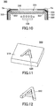
- Fig. 11 is a drawing illustrating an example of a printing plate 500.
- the printing plate 500 illustrated in Fig. 11 as an example has a recessed area 520 formed to take the shape of a letter "A".
- the recessed area 520 is formed such as to have a constant depth from a plate surface 510.
- Fig. 12 is a drawing illustrating an example of a printed deposit 530 printed by use of the printing plate 500 shown in Fig. 11 .
- the printed deposit 530 formed by transferring to a substrate the ink deposited in the recessed area 520 having a constant depth has a constant height from the print surface, thereby having an entirely even density.
- gradation may be created within the same printed deposit.
- a plurality of printing plates with recessed areas having different depths may be prepared, and a plurality of printing processes may be performed on one substrate.
- Such a method may entail an increase in printing costs due to an increase in the number of printing steps.
- a printing plate capable of readily forming a printed deposit having gradation.
- a printing plate having a recessed area to be filled with a print material to be transferred to a substrate includes at least one step situated in at least part of the recessed area and having a different depth than a bottom face of the recessed area.
- a printing plate capable of readily forming a printed deposit having gradation is provided.
- a printing plate of a present embodiment will be described first.
- Fig. 1 is a drawing illustrating an example of a printing plate 100 according to an embodiment.
- Figs. 2A and 2B are drawings illustrating a cross-section taken along the line A-A in Fig. 1.
- Fig. 2A is an axonometric cross-sectional view of the printing plate 100
- Fig. 2B is a cross-sectional view of the printing plate 100.
- the printing plate 100 illustrated in Fig. 1 and Figs. 2A and 2B has a recessed area 20 formed to take the shape of a letter "A" on a plate face 10.
- the recessed area 20 has a plurality of faces formed at different depths from the plate face 10.
- the recessed area 20 has steps 22 like a set of stairs comprised of a first step 22a and a second step 22b.
- the steps 22 include at least one step having a depth different from that of a bottom face 21 of the recessed area 20.
- the recessed area 20 is formed such that its depth gradually increases away from the plate face 10 in the following order: the first step 22a, the second step 22b, and the bottom face 21. Such an arrangement ensures that the depth does not exhibit a significant change between steps.
- the recessed area 20 is formed by etching.
- a plurality of etching processes are performed with respect to the printing plate 100 according to the present embodiment.
- a first etching process is performed while the areas of the plate face 10 other than the recessed area 20 are masked, thereby carving the plate up to the depth of the first step 22a.
- a second etching process is performed while the plate face 10 and part of the bottom surface at the depth of the first step 22a are masked, thereby carving the recessed area 20 up to the depth of the second step 22b.
- a third etching process is performed while the plate face 10, the first step 22a, and part of the bottom surface at the depth of the second step 22b are masked, thereby carving the recessed area 20 up to the depth of the bottom face 21.
- These processes serve to form in the printing plate 100 the recessed area 20 that takes the shape of a single letter comprised of a plurality of faces situated at respective different depths.
- a plurality of etching processes are performed to form the recessed area 20, so that the recessed area 20 having a plurality of faces at different depths is readily formed in the printing plate 100 with high dimensional precision.
- three faces are formed in the recessed area 20.
- the number of faces is not limited to this example.
- the recessed area 20 may alternatively be formed by other methods such as engraving.
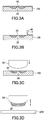
- ink 30 serving as a printing agent is applied to the printing plate 100 as illustrated in Fig. 3A .
- the recessed area 20 is filled with the ink 30.
- a blade 40 is then moved over the surface of the printing plate 100 while placed in contact with the surface, thereby removing excess ink from the printing plate 100. Scraping the ink 30 off the surface by use of the blade 40 leaves only the ink 30 deposited inside the recessed area 20 of the printing plate 100.
- a pad 50 serving as a transfer body is pressed onto the recessed area 20 of the printing plate 100, thereby transferring the ink 30 deposited in the recessed area 20 to the surface of the pad 50.
- the pad 50 which may be made of an elastic material such as a silicon rubber, elastically deforms upon being pressed onto the printing plate 100 or onto a substrate.
- the pad 50 having the ink 30 of the recessed area 20 attached thereto is pressed onto a surface of a substrate 200.
- the ink 30 is transferred from the pad 50 to the substrate 200.
- a printed deposit 31 having the same shape as the recessed area 20 of the printing plate 100 is formed on the surface of the substrate 200, as illustrated in Fig. 3E .
- Using the printing plate 100 having the recessed area 20 that takes the shape of a letter “A” as described above to perform printing by use of the method described above enables the provision of a print object 201 having the printed deposit 31 of a letter "A" formed on the surface of the substrate 200.
- the term "printed deposit” refers to a deposit formed on the surface of a substrate by transferring a print material such as ink deposited in a recessed area formed in a printing plate.
- Printing by use of a printing plate having a single recessed area causes a single printed deposit corresponding to such a recessed area to be formed on the surface of the substrate.
- Printing by use of a printing plate having a plurality of recessed areas causes a plurality of printed deposits corresponding to such recessed areas to be formed on the surface of the substrate.
- process steps different from the above-described steps may be used for printing as long as the ink 30 deposited in the recessed area 20 of the printing plate 100 can be transferred to the surface of the substrate 200.
- the pad 50 may not be used, and, instead, the ink 30 may directly be transferred to the surface of the substrate 200 from the recessed area 20 of the printing plate 100.
- Fig. 4 is a drawing illustrating an example of the printed deposit 31 according to an embodiment.
- Figs. 5A and 5B are drawings illustrating a cross-section taken along the line B-B in Fig. 4.
- Fig. 5A is an axonometric cross-sectional view of the printed deposit 31
- Fig. 5B is a cross-sectional view of the printed deposit 31.
- Fig. 6 is a plan view illustrating an example of the printed deposit 31 according to the embodiment.
- the printed deposit 31 is formed to take the shape of the same letter "A" as the recessed area 20 of the printing plate 100. Further, as illustrated in Fig. 5 , the outlines of the printed deposit 31 (i.e., the outer perimeter of the letter or the like formed by the printed deposit 31 and the inner perimeter formed by closed-loop lines inside the letter or the like) have printed steps 32 corresponding to the steps 22 formed in the recessed area 20 of the printing plate 100.
- the printed steps 32 include at least one step having a different height than the topmost face of the printed deposit 31.
- the printed steps 32 are formed such that the thickness of the ink (i.e., the vertical rise from the surface of the substrate 200) increases away from the surface of the substrate 200 in the following order: a first step 32a, a second step 32b, and a topmost step 33.
- the printing plate 100 illustrated in Fig. 1 and Figs. 2A and 2B has the deepest point at the location where the bottom face 21 is formed, so that the amount of ink 30 deposited at this location is the greatest.
- the first step 22a of the recessed area 20 is the shallowest face in the recessed area 20, so that the amount of ink 30 deposited at this location is the smallest. In this manner, the amount of ink 30 deposited in the recessed area 20 decreases in the following order: the bottom face 21 -> the second step 22b -> the first step 22a.
- the topmost step 33 of the printed deposit 31 illustrated in Fig. 4 through Fig. 6 corresponds to the bottom face 21 of the recessed area 20 in the printing plate 100, so that the printed thickness is the greatest.
- the first step 32a of the printed deposit 31 corresponds to the first step 22a of the recessed area 20, so that the printed thickness is the smallest.
- the printed deposit 31 of the present embodiment has the highest print density at the location corresponding to the topmost step 33, and the print density decreases at other locations corresponding to the second step 32b and the first step 32a in this order.
- the printed deposit 31 is formed such that print density increases in the following order: the first step 32a, the second step 32b, and the topmost step 33 as illustrated in Fig. 6 , so that the perimeter areas have multi-stage gradation formed therein.
- the use of the printing plate 100 according to the present embodiment enables a single printing process to readily form the printed deposit 31 having different densities as described above.
- the recessed area 20 of the printing plate 100 is not limited to the shape that was used as an example in the present embodiment, and may be formed to take any desired shape corresponding to a character or symbol to be printed.
- the steps 22 are formed along the entirety of the outlines (i.e., the outer perimeter of a letter or the like formed by the recessed area 20 and the inner perimeter formed by closed-loop lines inside the letter or the like) of the recessed area 20 in the printing plate 100.
- the steps 22 may be formed at only a part of the outlines of the recessed area 20 so as to create gradation at only a part of the printed deposit.
- the position at which the steps 22 are formed is not limited to the outlines of the recessed area 20.
- the steps 22 may be formed near the center of the recessed area 20 such that the density deceases from the outlines of a letter or the like toward the center.
- a set of the steps 22 is not limited to a two-step configuration comprised of the first step 22a and the second step 22b, and may alternatively be a one-step configuration or comprised of three or more steps such as to create multi-step gradation on a printed deposit.
- Figs. 7A and 7B are drawings illustrating a printing method according to a first comparative example.
- the printing method of the first comparative example uses a plurality of inks of different colors and a plurality of printing plates with recessed areas having different shapes to perform a plurality of printing processes, thereby forming a printed deposit having gradation.
- a printing plate with a recessed area taking the shape of a letter “A” is first used, with ink deposited in the recessed area for printing, thereby forming a printed deposit 701 taking the shape of a letter "A” on the surface of a substrate as illustrated in Fig. 7A .
- a printing plate with a recessed area taking such a shape as to add fringes to the printed deposit 701 is then used, with ink deposited in the recessed area and having a different color than the printed deposit 701, thereby printing over the printed deposit 701.
- a printed deposit 702 is formed around the printed deposit 701 as illustrated in Fig. 7B .
- a plurality of printing processes are performed by using a plurality of inks of different colors and using a plurality of printing plates with recessed areas having different shapes, thereby forming a letter or symbol having gradation as illustrated in Fig. 7B .
- the depth of the recessed area of the printing plate for forming the printed deposit 702 may be made shallower than the recessed area of the printing plate for forming the printed deposit 701, thereby allowing the same ink to be used to form the printed deposit 701 and the printed deposit 702.
- the thickness of the printed deposit 702 becomes shallower than the thickness of the printed deposit 701.
- the amount of ink at the position of the printed deposit 702 smaller than the amount of ink at the position of the printed deposit 701 enables the formation of a letter or symbol having gradation.
- the printing method of the first comparative example described above requires a plurality of printing processes to be performed by use of a plurality of printing plates with recessed areas having different shapes, which may lead to an increase in process steps and an increase in printing costs.
- Figs. 8A and 8B are drawings illustrating a printing method according to a second comparative example.
- Fig. 8A is a drawing illustrating an example of a printed deposit 800 formed on a surface of a substrate.
- Fig. 8B is a drawing illustrating a cross-section taken along the line D-D in Fig. 8A .
- the printing method of the second comparative example forms the printed deposit 800 having gradation by changing dot density on an area-specific basis.
- the density of dots 810 constituting the printed deposit 800 decreases in the following order: an area 801, an area 802, an area 803, and an area 804. Printing in such a manner allows the printed deposit 800 to be formed such that the density gradually changes from the darkest-tone area 801 to the lightest-tone area 804.
- the above-described method gives rise to a problem in that the dots 810 become conspicuous as the density of the dots 810 is decreased to provide lighter tones, failing to provide an even tone across the entire area.
- a keycap serving as an example of a substrate will be described with reference to the accompanying drawings.
- the keycap described in the following may be used for a keyboard for a PC or as a button of various kinds for a portable phone, a calculator, or the like.
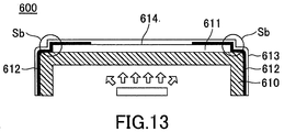
- Fig. 13 is a drawing illustrating an example of a keycap 600 with a printed layer having a uniform printed thickness formed on a frame 610.
- the keycap 600 illustrated in Fig. 13 includes the frame 610, a printed layer 611 formed on the upper face of the frame 610, a light blocking layer 612 covering the printed layer 611, and a coating layer 613 covering the printed layer 611 and the light blocking layer 612.
- the printed layer 611 which is made of a print material allowing light to pass through, is formed on the entire upper face of the frame 610.
- the light blocking layer 612 is made of a black paint or the like. Specifically, the paint is applied or printed to cover the entirety of the frame 610 and the printed layer 611, followed by removing the paint at the position of a character portion 614 taking the shape of a letter or the like to form the light blocking layer 612.
- the coating layer 613 which is made of a material such as a transparent resin allowing light to pass through, is formed to cover the light blocking layer 612 and the printed layer 611 exposed through the light blocking layer 612.
- the keycap 600 is such that light emitted from a light source disposed under the frame 610, for example, passes through the frame 610, the printed layer 611, and the coating layer 613. With this arrangement, the character portion 614 shaped by the light blocking layer 612 glows.
- Forming the printed layer 611 with a constant printed thickness on the upper face of the frame 610 as illustrated in Fig. 13 may increase the size of a step at a perimeter Sb of the light blocking layer 612 covering the printed layer 611, thereby lowering the aesthetic value of the keycap 600.
- Fig. 9 is a drawing illustrating an example of a keycap 300 according to an embodiment.
- Fig. 10 is a cross-sectional view taken along the line C-C in Fig. 9 .
- a keycap 300 illustrated in Fig. 9 and Fig. 10 which is used for a type of keyboard known as a backlight keyboard, has a character portion 310 formed thereon.
- the character portion 310 allows light emitted from a light source 330 under the keycap 300 to pass therethrough.
- the light source 330 is schematically illustrated.
- an example illustrated in Fig. 10 has a configuration in which the light source 330 is situated under the keycap 300, a different configuration may be used in which a light guide plate or the like for guiding light form a light source situated somewhere else is disposed such as to illuminate the keycap 300 from underneath.
- the keycap 300 includes a frame 320, a printed deposit 321, a light blocking layer 323 serving as a coated layer, and a coating layer 324.
- the frame 320 is made of a material such as a transparent resin allowing light to pass through.
- the upper face of the frame 320 has the printed deposit 321 formed thereon to cover the entire upper face of the frame 320.
- the printed deposit 321 is formed on the upper face of the frame 320 by a printing method previously described, which uses a printing plate with a recessed area having stair-like steps formed along the perimeter thereof.
- the printed deposit 321 is made of a print material allowing light to pass through.
- the printed deposit 321 has stair-like printed steps 322 on the side face thereof as illustrated in Fig. 10 .
- the light blocking layer 323, which is made of a black paint or the like allowing no light to pass through, is formed to cover at least the printed steps 322 of the printed deposit 321. Specifically, the light blocking layer 323 is formed by applying or printing the paint or the like such as to cover the printed deposit 321 and the frame 320, followed by removing the paint at the position of the character portion 310.
- the coating layer 324 which may be made of a material such as a transparent resin allowing light to pass through, is formed to cover the light blocking layer 323 and the printed deposit 321 exposed through the light blocking layer 323.
- the keycap 300 which has the configuration described above, allows light from the light source 330 to pass through the frame 320, the printed deposit 321, and the coating layer 324, so that the character portion 310 shaped by the light blocking layer 323 glows.
- the illustrated keycap 300 has a letter "A" formed at the character portion 310, a different character or symbol may be formed, or a plurality of characters or symbols may be formed.
- the printed layer 611 having an even printed thickness as illustrated in Fig. 13 is formed on the upper face of the frame 610, a large step is formed at the perimeter Sb of the light blocking layer 612 covering the printed layer 611. As a result, the step of the printed layer 611 becomes conspicuous especially when the light blocking layer 612 is formed by using a black ink as a print material, thereby undermining the appearance of the keycap 600.
- the keycap 300 of the present embodiment has the printed steps 322 formed at the side faces of the printed deposit 321, so that the thickness of the printed deposit 321 exhibits gradual stair-like increases.
- the height of each of the steps between the printed deposit 321 and the frame 320 is smaller than in the example illustrated in Fig. 13 .
- the steps at a perimeter Sa of the light blocking layer 323 are made inconspicuous due to the fact that these steps formed by the printed deposit 321 and the light blocking layer 323 are smaller than in the example illustrated in Fig. 13 .
- Aesthetic value thus improves.
- the use of the printing plate 100 of the present embodiment allows a single printing process to readily form a printed deposit having gradation that exhibits stair-like density changes along the perimeter thereof. Further, a substrate such as a keycap with improved aesthetic value can be manufactured.
Landscapes
- Printing Methods (AREA)
- Printing Plates And Materials Therefor (AREA)
Abstract

Description
- The disclosures herein relate to a printing plate, a substrate, and a printing method.
- In pad printing known in the art, ink deposited in a recessed area formed in a printing plate is transferred to a pad, and the ink transferred on the pad is then transferred to a substrate, thereby printing, on the surface of the substrate, characters or symbols corresponding to the shape of the recessed area of the printing plate. A method of such pad printing that forms a plurality of recessed areas in a printing plate to print a mark having a plurality of constituent elements, for example, is known in the art (see
Patent Document 1, for example). - [Patent Document 1] Japanese Patent Application Publication No.
2002-362001 - In pad printing described above, recesses in a printing plate are generally formed such as to have a constant depth from the plate surface.
-
Fig. 11 is a drawing illustrating an example of aprinting plate 500. Theprinting plate 500 illustrated inFig. 11 as an example has arecessed area 520 formed to take the shape of a letter "A". Therecessed area 520 is formed such as to have a constant depth from aplate surface 510. -
Fig. 12 is a drawing illustrating an example of a printeddeposit 530 printed by use of theprinting plate 500 shown inFig. 11 . As is illustrated inFig. 12 , the printeddeposit 530 formed by transferring to a substrate the ink deposited in therecessed area 520 having a constant depth has a constant height from the print surface, thereby having an entirely even density. - In order to improve the design, gradation may be created within the same printed deposit. In such a case, a plurality of printing plates with recessed areas having different depths may be prepared, and a plurality of printing processes may be performed on one substrate. Such a method, however, may entail an increase in printing costs due to an increase in the number of printing steps.
- In consideration of this, it may be desired to provide a printing plate capable of readily forming a printed deposit having gradation.
- According to an embodiment, a printing plate having a recessed area to be filled with a print material to be transferred to a substrate includes at least one step situated in at least part of the recessed area and having a different depth than a bottom face of the recessed area.
- According to at least one embodiment, a printing plate capable of readily forming a printed deposit having gradation is provided.
-
-
Fig. 1 is a drawing illustrating an example of a printing plate according to an embodiment. -
Fig. 2A is an axonometric cross-sectional view illustrating an example of the printing plate according to the embodiment. -
Fig. 2B is a cross-sectional view illustrating an example of the printing plate according to the embodiment. -
Fig. 3A is a drawing illustrating an example of a printing method according to an embodiment. -
Fig. 3B is a drawing illustrating the example of a printing method according to the embodiment. -
Fig. 3C is a drawing illustrating the example of a printing method according to the embodiment. -
Fig. 3D is a drawing illustrating the example of a printing method according to the embodiment. -
Fig. 3E is a drawing illustrating the example of a printing method according to the embodiment. -
Fig. 4 is a drawing illustrating an example of a printed deposit according to the embodiment. -
Fig. 5A is an axonometric cross-sectional view illustrating the example of a printed deposit according to the embodiment. -
Fig. 5B is a cross-sectional view illustrating the example of a printed deposit according to the embodiment. -
Fig. 6 is a plan view illustrating the example of a printed deposit according to the embodiment. -
Fig. 7A is a drawing illustrating a printing method according to a first comparative example. -
Fig. 7B is a drawing illustrating the printing method according to the first comparative example. -
Fig. 8A is a drawing illustrating a printing method according to a second comparative example. -
Fig. 8B is a drawing illustrating the printing method according to the second comparative example. -
Fig. 9 is a drawing illustrating an example of a keycap according to an embodiment. -
Fig. 10 is a drawing illustrating the example of a keycap according to an embodiment. -
Fig. 11 is a drawing illustrating an example of a printing plate. -
Fig. 12 is a drawing illustrating an example of a printed character. -
Fig. 13 is a cross-sectional view illustrating an example of a keycap. - In the following, embodiments will be described by referring to the accompanying drawings. In these drawings, the same elements are referred to by the same references, and a description thereof may be omitted.
- A printing plate of a present embodiment will be described first.
-
Fig. 1 is a drawing illustrating an example of aprinting plate 100 according to an embodiment.Figs. 2A and 2B are drawings illustrating a cross-section taken along the line A-A inFig. 1. Fig. 2A is an axonometric cross-sectional view of theprinting plate 100, andFig. 2B is a cross-sectional view of theprinting plate 100. - The
printing plate 100 illustrated inFig. 1 and Figs. 2A and 2B has a recessedarea 20 formed to take the shape of a letter "A" on aplate face 10. The recessedarea 20 has a plurality of faces formed at different depths from theplate face 10. As is understood fromFigs. 2A and 2B , the recessedarea 20 hassteps 22 like a set of stairs comprised of afirst step 22a and asecond step 22b. Thesteps 22 include at least one step having a depth different from that of abottom face 21 of the recessedarea 20. The recessedarea 20 is formed such that its depth gradually increases away from theplate face 10 in the following order: thefirst step 22a, thesecond step 22b, and thebottom face 21. Such an arrangement ensures that the depth does not exhibit a significant change between steps. - The recessed
area 20 is formed by etching. In order to form the recessedarea 20 having faces at different depths as illustrated inFig. 1 and Figs. 2A and 2B , a plurality of etching processes are performed with respect to theprinting plate 100 according to the present embodiment. In the recessedarea 20, a first etching process is performed while the areas of theplate face 10 other than the recessedarea 20 are masked, thereby carving the plate up to the depth of thefirst step 22a. Then, a second etching process is performed while theplate face 10 and part of the bottom surface at the depth of thefirst step 22a are masked, thereby carving the recessedarea 20 up to the depth of thesecond step 22b. Subsequently, a third etching process is performed while theplate face 10, thefirst step 22a, and part of the bottom surface at the depth of thesecond step 22b are masked, thereby carving the recessedarea 20 up to the depth of thebottom face 21. These processes serve to form in theprinting plate 100 the recessedarea 20 that takes the shape of a single letter comprised of a plurality of faces situated at respective different depths. - In this manner, a plurality of etching processes are performed to form the recessed
area 20, so that the recessedarea 20 having a plurality of faces at different depths is readily formed in theprinting plate 100 with high dimensional precision. In the example illustrated inFig. 1 and Figs. 2A and 2B , three faces are formed in the recessedarea 20. However, the number of faces is not limited to this example. Further, the recessedarea 20 may alternatively be formed by other methods such as engraving. - In the following, a printing method using the
printing plate 100 described above will be described with reference toFigs. 3A through 3E . In so doing, an example of pad printing will be described. - In the printing method according to the present embodiment,
ink 30 serving as a printing agent is applied to theprinting plate 100 as illustrated inFig. 3A . As a result, the recessedarea 20 is filled with theink 30. - As illustrated in
Fig. 3B , ablade 40 is then moved over the surface of theprinting plate 100 while placed in contact with the surface, thereby removing excess ink from theprinting plate 100. Scraping theink 30 off the surface by use of theblade 40 leaves only theink 30 deposited inside the recessedarea 20 of theprinting plate 100. - Subsequently, as illustrated in
Fig. 3C , apad 50 serving as a transfer body is pressed onto the recessedarea 20 of theprinting plate 100, thereby transferring theink 30 deposited in the recessedarea 20 to the surface of thepad 50. Thepad 50, which may be made of an elastic material such as a silicon rubber, elastically deforms upon being pressed onto theprinting plate 100 or onto a substrate. - Thereafter, as illustrated in
Fig. 3D , thepad 50 having theink 30 of the recessedarea 20 attached thereto is pressed onto a surface of asubstrate 200. With this, theink 30 is transferred from thepad 50 to thesubstrate 200. As the transferredink 30 dries to adhere to the surface of thesubstrate 200, a printeddeposit 31 having the same shape as the recessedarea 20 of theprinting plate 100 is formed on the surface of thesubstrate 200, as illustrated inFig. 3E . - Using the
printing plate 100 having the recessedarea 20 that takes the shape of a letter "A" as described above to perform printing by use of the method described above enables the provision of aprint object 201 having the printeddeposit 31 of a letter "A" formed on the surface of thesubstrate 200. - Here, the term "printed deposit" refers to a deposit formed on the surface of a substrate by transferring a print material such as ink deposited in a recessed area formed in a printing plate. Printing by use of a printing plate having a single recessed area, for example, causes a single printed deposit corresponding to such a recessed area to be formed on the surface of the substrate. Printing by use of a printing plate having a plurality of recessed areas, for example, causes a plurality of printed deposits corresponding to such recessed areas to be formed on the surface of the substrate.
- It may be noted that process steps different from the above-described steps may be used for printing as long as the
ink 30 deposited in the recessedarea 20 of theprinting plate 100 can be transferred to the surface of thesubstrate 200. For example, thepad 50 may not be used, and, instead, theink 30 may directly be transferred to the surface of thesubstrate 200 from the recessedarea 20 of theprinting plate 100. - In the following, the printed
deposit 31 printed by use of theprinting plate 100 will be described with reference toFig. 4 through Fig. 6 . -
Fig. 4 is a drawing illustrating an example of the printeddeposit 31 according to an embodiment.Figs. 5A and 5B are drawings illustrating a cross-section taken along the line B-B inFig. 4. Fig. 5A is an axonometric cross-sectional view of the printeddeposit 31, andFig. 5B is a cross-sectional view of the printeddeposit 31.Fig. 6 is a plan view illustrating an example of the printeddeposit 31 according to the embodiment. - As illustrated in
Fig. 4 , the printeddeposit 31 is formed to take the shape of the same letter "A" as the recessedarea 20 of theprinting plate 100. Further, as illustrated inFig. 5 , the outlines of the printed deposit 31 (i.e., the outer perimeter of the letter or the like formed by the printeddeposit 31 and the inner perimeter formed by closed-loop lines inside the letter or the like) have printedsteps 32 corresponding to thesteps 22 formed in the recessedarea 20 of theprinting plate 100. The printed steps 32 include at least one step having a different height than the topmost face of the printeddeposit 31. The printed steps 32 are formed such that the thickness of the ink (i.e., the vertical rise from the surface of the substrate 200) increases away from the surface of thesubstrate 200 in the following order: afirst step 32a, asecond step 32b, and atopmost step 33. - The
printing plate 100 illustrated inFig. 1 and Figs. 2A and 2B has the deepest point at the location where thebottom face 21 is formed, so that the amount ofink 30 deposited at this location is the greatest. In contrast, thefirst step 22a of the recessedarea 20 is the shallowest face in the recessedarea 20, so that the amount ofink 30 deposited at this location is the smallest. In this manner, the amount ofink 30 deposited in the recessedarea 20 decreases in the following order: the bottom face 21 -> thesecond step 22b -> thefirst step 22a. - The
topmost step 33 of the printeddeposit 31 illustrated inFig. 4 through Fig. 6 corresponds to thebottom face 21 of the recessedarea 20 in theprinting plate 100, so that the printed thickness is the greatest. In contrast, thefirst step 32a of the printeddeposit 31 corresponds to thefirst step 22a of the recessedarea 20, so that the printed thickness is the smallest. - The portion of the printed
deposit 31 having a great printed thickness creates a high print density due to the large amount of ink, and the portion having a small printed thickness creates a low print density due to the small amount of ink. Accordingly, the printeddeposit 31 of the present embodiment has the highest print density at the location corresponding to thetopmost step 33, and the print density decreases at other locations corresponding to thesecond step 32b and thefirst step 32a in this order. - As described above, the printed
deposit 31 is formed such that print density increases in the following order: thefirst step 32a, thesecond step 32b, and thetopmost step 33 as illustrated inFig. 6 , so that the perimeter areas have multi-stage gradation formed therein. - The use of the
printing plate 100 according to the present embodiment enables a single printing process to readily form the printeddeposit 31 having different densities as described above. - The recessed
area 20 of theprinting plate 100 is not limited to the shape that was used as an example in the present embodiment, and may be formed to take any desired shape corresponding to a character or symbol to be printed. In the embodiment described above, further, thesteps 22 are formed along the entirety of the outlines (i.e., the outer perimeter of a letter or the like formed by the recessedarea 20 and the inner perimeter formed by closed-loop lines inside the letter or the like) of the recessedarea 20 in theprinting plate 100. Alternatively, thesteps 22 may be formed at only a part of the outlines of the recessedarea 20 so as to create gradation at only a part of the printed deposit. The position at which thesteps 22 are formed is not limited to the outlines of the recessedarea 20. For example, thesteps 22 may be formed near the center of the recessedarea 20 such that the density deceases from the outlines of a letter or the like toward the center. Further, a set of thesteps 22 is not limited to a two-step configuration comprised of thefirst step 22a and thesecond step 22b, and may alternatively be a one-step configuration or comprised of three or more steps such as to create multi-step gradation on a printed deposit. -
Figs. 7A and 7B are drawings illustrating a printing method according to a first comparative example. The printing method of the first comparative example uses a plurality of inks of different colors and a plurality of printing plates with recessed areas having different shapes to perform a plurality of printing processes, thereby forming a printed deposit having gradation. - A printing plate with a recessed area taking the shape of a letter "A" is first used, with ink deposited in the recessed area for printing, thereby forming a printed
deposit 701 taking the shape of a letter "A" on the surface of a substrate as illustrated inFig. 7A . - A printing plate with a recessed area taking such a shape as to add fringes to the printed
deposit 701 is then used, with ink deposited in the recessed area and having a different color than the printeddeposit 701, thereby printing over the printeddeposit 701. As a result, a printeddeposit 702 is formed around the printeddeposit 701 as illustrated inFig. 7B . - In this manner, a plurality of printing processes are performed by using a plurality of inks of different colors and using a plurality of printing plates with recessed areas having different shapes, thereby forming a letter or symbol having gradation as illustrated in
Fig. 7B . - Alternatively, the depth of the recessed area of the printing plate for forming the printed
deposit 702 may be made shallower than the recessed area of the printing plate for forming the printeddeposit 701, thereby allowing the same ink to be used to form the printeddeposit 701 and the printeddeposit 702. In such a case, the thickness of the printeddeposit 702 becomes shallower than the thickness of the printeddeposit 701. The amount of ink at the position of the printeddeposit 702 smaller than the amount of ink at the position of the printeddeposit 701 enables the formation of a letter or symbol having gradation. - The printing method of the first comparative example described above requires a plurality of printing processes to be performed by use of a plurality of printing plates with recessed areas having different shapes, which may lead to an increase in process steps and an increase in printing costs.
-
Figs. 8A and 8B are drawings illustrating a printing method according to a second comparative example.Fig. 8A is a drawing illustrating an example of a printeddeposit 800 formed on a surface of a substrate.Fig. 8B is a drawing illustrating a cross-section taken along the line D-D inFig. 8A . The printing method of the second comparative example forms the printeddeposit 800 having gradation by changing dot density on an area-specific basis. - As illustrated in
Figs. 8A and 8B , the density ofdots 810 constituting the printeddeposit 800 decreases in the following order: anarea 801, anarea 802, anarea 803, and anarea 804. Printing in such a manner allows the printeddeposit 800 to be formed such that the density gradually changes from the darkest-tone area 801 to the lightest-tone area 804. - The above-described method gives rise to a problem in that the
dots 810 become conspicuous as the density of thedots 810 is decreased to provide lighter tones, failing to provide an even tone across the entire area. - In the following, a keycap serving as an example of a substrate will be described with reference to the accompanying drawings. The keycap described in the following may be used for a keyboard for a PC or as a button of various kinds for a portable phone, a calculator, or the like.
-
Fig. 13 is a drawing illustrating an example of akeycap 600 with a printed layer having a uniform printed thickness formed on aframe 610. - The
keycap 600 illustrated inFig. 13 includes theframe 610, a printedlayer 611 formed on the upper face of theframe 610, alight blocking layer 612 covering the printedlayer 611, and acoating layer 613 covering the printedlayer 611 and thelight blocking layer 612. - The printed
layer 611, which is made of a print material allowing light to pass through, is formed on the entire upper face of theframe 610. Thelight blocking layer 612 is made of a black paint or the like. Specifically, the paint is applied or printed to cover the entirety of theframe 610 and the printedlayer 611, followed by removing the paint at the position of acharacter portion 614 taking the shape of a letter or the like to form thelight blocking layer 612. Thecoating layer 613, which is made of a material such as a transparent resin allowing light to pass through, is formed to cover thelight blocking layer 612 and the printedlayer 611 exposed through thelight blocking layer 612. - The
keycap 600 is such that light emitted from a light source disposed under theframe 610, for example, passes through theframe 610, the printedlayer 611, and thecoating layer 613. With this arrangement, thecharacter portion 614 shaped by thelight blocking layer 612 glows. - Forming the printed
layer 611 with a constant printed thickness on the upper face of theframe 610 as illustrated inFig. 13 , however, may increase the size of a step at a perimeter Sb of thelight blocking layer 612 covering the printedlayer 611, thereby lowering the aesthetic value of thekeycap 600. -
Fig. 9 is a drawing illustrating an example of akeycap 300 according to an embodiment.Fig. 10 is a cross-sectional view taken along the line C-C inFig. 9 . - A
keycap 300 illustrated inFig. 9 andFig. 10 , which is used for a type of keyboard known as a backlight keyboard, has acharacter portion 310 formed thereon. Thecharacter portion 310 allows light emitted from alight source 330 under thekeycap 300 to pass therethrough. InFig. 10 , thelight source 330 is schematically illustrated. Although an example illustrated inFig. 10 has a configuration in which thelight source 330 is situated under thekeycap 300, a different configuration may be used in which a light guide plate or the like for guiding light form a light source situated somewhere else is disposed such as to illuminate thekeycap 300 from underneath. - The
keycap 300 includes aframe 320, a printeddeposit 321, alight blocking layer 323 serving as a coated layer, and acoating layer 324. - The
frame 320 is made of a material such as a transparent resin allowing light to pass through. The upper face of theframe 320 has the printeddeposit 321 formed thereon to cover the entire upper face of theframe 320. - The printed
deposit 321 is formed on the upper face of theframe 320 by a printing method previously described, which uses a printing plate with a recessed area having stair-like steps formed along the perimeter thereof. The printeddeposit 321 is made of a print material allowing light to pass through. The printeddeposit 321 has stair-like printedsteps 322 on the side face thereof as illustrated inFig. 10 . - The
light blocking layer 323, which is made of a black paint or the like allowing no light to pass through, is formed to cover at least the printedsteps 322 of the printeddeposit 321. Specifically, thelight blocking layer 323 is formed by applying or printing the paint or the like such as to cover the printeddeposit 321 and theframe 320, followed by removing the paint at the position of thecharacter portion 310. - The
coating layer 324, which may be made of a material such as a transparent resin allowing light to pass through, is formed to cover thelight blocking layer 323 and the printeddeposit 321 exposed through thelight blocking layer 323. - The
keycap 300, which has the configuration described above, allows light from thelight source 330 to pass through theframe 320, the printeddeposit 321, and thecoating layer 324, so that thecharacter portion 310 shaped by thelight blocking layer 323 glows. Although the illustratedkeycap 300 has a letter "A" formed at thecharacter portion 310, a different character or symbol may be formed, or a plurality of characters or symbols may be formed. - When the printed
layer 611 having an even printed thickness as illustrated inFig. 13 is formed on the upper face of theframe 610, a large step is formed at the perimeter Sb of thelight blocking layer 612 covering the printedlayer 611. As a result, the step of the printedlayer 611 becomes conspicuous especially when thelight blocking layer 612 is formed by using a black ink as a print material, thereby undermining the appearance of thekeycap 600. - In contrast, the
keycap 300 of the present embodiment has the printedsteps 322 formed at the side faces of the printeddeposit 321, so that the thickness of the printeddeposit 321 exhibits gradual stair-like increases. As illustrated inFig. 10 , thus, the height of each of the steps between the printeddeposit 321 and theframe 320 is smaller than in the example illustrated inFig. 13 . Accordingly, even when thelight blocking layer 323 is formed by using a black ink or the like, the steps at a perimeter Sa of thelight blocking layer 323 are made inconspicuous due to the fact that these steps formed by the printeddeposit 321 and thelight blocking layer 323 are smaller than in the example illustrated inFig. 13 . Aesthetic value thus improves. - When considering the issue of elimination of a step on a keycap, the same or similar functions and advantages are provided even when the keycap of interest is not for a backlight keyboard.
- As has been described heretofore, the use of the
printing plate 100 of the present embodiment allows a single printing process to readily form a printed deposit having gradation that exhibits stair-like density changes along the perimeter thereof. Further, a substrate such as a keycap with improved aesthetic value can be manufactured. - Although a printing plate, a substrate, and a printing method have heretofore been described according to the embodiments, the present invention is not limited to those embodiments. Various changes and modifications may be made without departing from the scope of the invention.
- The present application claims foreign priority to Japanese priority application No.
2015-146071 filed on July 23, 2015 -
- 10
- plate face
- 20
- recessed area
- 22
- step
- 30
- ink (print material)
- 31
- printed deposit
- 100
- printing plate
- 200
- substrate
- 201
- print object
- 300
- keycap (substrate)
- 321
- printed deposit
- 322
- printed step
- 323
- light blocking layer (coated layer)
Claims (4)
- A printing plate having a recessed area to be filled with a print material to be transferred to a substrate, comprising
at least one step situated in at least part of the recessed area and having a different depth than a bottom face of the recessed area. - The printing plate as claimed in claim 1, wherein the step is made by etching.
- A substrate, comprising:a printed deposit having at least one step having a different height than a topmost face thereof, the step being situated at least at part thereof; anda coating layer covering the step.
- A printing method utilizing a printing plate with a recessed area, comprising:a depositing step of depositing a print material in the recessed area, the recessed area having at least one step that is situated in at least part thereof and that has a different depth than a bottom face of the recessed area;a first transfer step of transferring the print material deposited in the recessed area onto a transfer body; anda second transfer step of transferring the print material transferred onto the transfer body to a substrate to form a printed deposit.
Applications Claiming Priority (2)
| Application Number | Priority Date | Filing Date | Title |
|---|---|---|---|
| JP2015146071A JP2017024295A (en) | 2015-07-23 | 2015-07-23 | Printing plate, printed matter and printing method |
| PCT/JP2016/070118 WO2017014056A1 (en) | 2015-07-23 | 2016-07-07 | Printing plate, printed matter, and printing method |
Publications (2)
| Publication Number | Publication Date |
|---|---|
| EP3326830A1 true EP3326830A1 (en) | 2018-05-30 |
| EP3326830A4 EP3326830A4 (en) | 2019-04-03 |
Family
ID=57834007
Family Applications (1)
| Application Number | Title | Priority Date | Filing Date |
|---|---|---|---|
| EP16827618.6A Withdrawn EP3326830A4 (en) | 2015-07-23 | 2016-07-07 | PRINTING PLATE, PRINTED MATERIAL, AND PRINTING METHOD |
Country Status (5)
| Country | Link |
|---|---|
| US (1) | US20180207969A1 (en) |
| EP (1) | EP3326830A4 (en) |
| JP (1) | JP2017024295A (en) |
| CN (1) | CN107848318A (en) |
| WO (1) | WO2017014056A1 (en) |
Families Citing this family (5)
| Publication number | Priority date | Publication date | Assignee | Title |
|---|---|---|---|---|
| JP6901891B2 (en) * | 2017-03-30 | 2021-07-14 | トッパン・フォームズ株式会社 | Printing equipment and manufacturing method of printed matter using it |
| JP7600539B2 (en) * | 2020-05-07 | 2024-12-17 | 東洋製罐株式会社 | Printing device, printing method and can body |
| US11857847B2 (en) * | 2022-02-02 | 2024-01-02 | Acushnet Company | Golf ball having overlap markings |
| KR20240164550A (en) * | 2023-05-11 | 2024-11-19 | 가부시키가이샤 슈호 | Printed matter and methods of making printed matter |
| CN117534985B (en) * | 2023-11-09 | 2026-04-07 | Oppo广东移动通信有限公司 | Ink, cover plate assembly, preparation method of cover plate assembly and electronic equipment |
Family Cites Families (11)
| Publication number | Priority date | Publication date | Assignee | Title |
|---|---|---|---|---|
| JPH02106349A (en) * | 1988-10-14 | 1990-04-18 | Nabitasu Kk | Printing plate for uv ink in pad printer |
| DE4027587C1 (en) * | 1990-08-31 | 1991-10-02 | Tampoprint Gmbh, 7015 Korntal-Muenchingen, De | |
| JPH1035129A (en) * | 1996-07-25 | 1998-02-10 | Sumitomo Rubber Ind Ltd | Intaglio for printing and its manufacturing method |
| DE19845436C5 (en) * | 1998-10-02 | 2015-02-26 | Giesecke & Devrient Gmbh | Intaglio printing method for printing adjacent color areas of different ink layer thickness, data carrier with printed image produced by intaglio printing, printing plate and method for producing a printing plate |
| JP3533600B2 (en) * | 1999-09-08 | 2004-05-31 | リコーマイクロエレクトロニクス株式会社 | Intaglio, intaglio production method and apparatus |
| JP2002362001A (en) * | 2001-06-05 | 2002-12-18 | Sumitomo Rubber Ind Ltd | Mark printing method and golf ball using the same |
| JP4230485B2 (en) * | 2005-11-30 | 2009-02-25 | 株式会社棚澤八光社 | Product having convex pattern on surface and method for forming convex pattern |
| CN103465525B (en) * | 2006-12-27 | 2015-10-21 | 日立化成株式会社 | The base material with conductor layer pattern of intaglio plate and this intaglio plate of use |
| EP2119527A1 (en) * | 2008-05-16 | 2009-11-18 | Kba-Giori S.A. | Method and system for manufacturing intaglio printing plates for the production of security papers |
| EP2159069A1 (en) * | 2008-08-29 | 2010-03-03 | Kba-Giori S.A. | Method for varnishing security documents, especially intaglio-printed security documents such as banknotes, and varnishing machine for carrying out the same |
| KR101385843B1 (en) * | 2011-09-27 | 2014-04-17 | 주식회사 엘지화학 | Cliche for offset printing and method for preparing the same |
-
2015
- 2015-07-23 JP JP2015146071A patent/JP2017024295A/en active Pending
-
2016
- 2016-07-07 WO PCT/JP2016/070118 patent/WO2017014056A1/en not_active Ceased
- 2016-07-07 US US15/744,323 patent/US20180207969A1/en not_active Abandoned
- 2016-07-07 EP EP16827618.6A patent/EP3326830A4/en not_active Withdrawn
- 2016-07-07 CN CN201680042438.3A patent/CN107848318A/en active Pending
Also Published As
| Publication number | Publication date |
|---|---|
| CN107848318A (en) | 2018-03-27 |
| WO2017014056A1 (en) | 2017-01-26 |
| EP3326830A4 (en) | 2019-04-03 |
| JP2017024295A (en) | 2017-02-02 |
| US20180207969A1 (en) | 2018-07-26 |
Similar Documents
| Publication | Publication Date | Title |
|---|---|---|
| EP3326830A1 (en) | Printing plate, printed matter, and printing method | |
| PL190716B1 (en) | Gravure process for full printing of large surfaces | |
| US20110223352A1 (en) | Method of making a keycap structure | |
| KR100920131B1 (en) | Manufacturing method of Jeonju Deco product using UV pattern growth | |
| US10882073B2 (en) | Method for manufacturing decorated article by decorating uneven surface, decorated article by decorating uneven surface, and method for manufacturing drawn article | |
| JP4306371B2 (en) | Key unit for mobile devices | |
| WO2024150972A3 (en) | Color-variable glossy film | |
| WO2012073994A1 (en) | Decorated film | |
| CN111452552B (en) | Decorative films and electronic devices | |
| CN204641036U (en) | A kind of modified form gravure printing roller | |
| RU2010114849A (en) | DATA CARRIER EQUIPPED BY A DRAWING EXECUTED BY METAL PRINTING | |
| US20130089714A1 (en) | Surface decoration method and electronic device | |
| KR20100075527A (en) | Key sheet | |
| JP6832915B2 (en) | Printing equipment and printing method | |
| CN109246950B (en) | Manufacturing method of cover plate with gradually changed colors, cover plate and electronic equipment | |
| EP2678161B1 (en) | Rotogravure printing device | |
| US20190276946A1 (en) | Method of producing high resolution multicolored line art images via anodization of refractory metals | |
| CN220808846U (en) | Plate roller and gravure printing device | |
| AU2003233876A1 (en) | Improvements in printing processes using metallic inks | |
| KR100878340B1 (en) | Key pad manufacturing method | |
| JP2013031941A (en) | Metallic shrink film, shrink label, and method for manufacturing the same | |
| CN110816093A (en) | Processing technology of seal type ink for printed circuit board | |
| KR100717523B1 (en) | Keypad and its manufacturing method | |
| JP6549408B2 (en) | Printing plate and method for manufacturing the same | |
| CN210000252U (en) | Vehicle label |
Legal Events
| Date | Code | Title | Description |
|---|---|---|---|
| STAA | Information on the status of an ep patent application or granted ep patent |
Free format text: STATUS: THE INTERNATIONAL PUBLICATION HAS BEEN MADE |
|
| PUAI | Public reference made under article 153(3) epc to a published international application that has entered the european phase |
Free format text: ORIGINAL CODE: 0009012 |
|
| STAA | Information on the status of an ep patent application or granted ep patent |
Free format text: STATUS: REQUEST FOR EXAMINATION WAS MADE |
|
| 17P | Request for examination filed |
Effective date: 20180117 |
|
| AK | Designated contracting states |
Kind code of ref document: A1 Designated state(s): AL AT BE BG CH CY CZ DE DK EE ES FI FR GB GR HR HU IE IS IT LI LT LU LV MC MK MT NL NO PL PT RO RS SE SI SK SM TR |
|
| AX | Request for extension of the european patent |
Extension state: BA ME |
|
| DAV | Request for validation of the european patent (deleted) | ||
| DAX | Request for extension of the european patent (deleted) | ||
| A4 | Supplementary search report drawn up and despatched |
Effective date: 20190228 |
|
| RIC1 | Information provided on ipc code assigned before grant |
Ipc: B41M 5/03 20060101ALI20190222BHEP Ipc: B41M 1/00 20060101ALI20190222BHEP Ipc: B41C 1/02 20060101ALN20190222BHEP Ipc: B41F 17/00 20060101ALI20190222BHEP Ipc: B41C 1/05 20060101ALN20190222BHEP Ipc: B41N 1/06 20060101AFI20190222BHEP |
|
| STAA | Information on the status of an ep patent application or granted ep patent |
Free format text: STATUS: THE APPLICATION IS DEEMED TO BE WITHDRAWN |
|
| 18D | Application deemed to be withdrawn |
Effective date: 20191001 |