EP3325721B1 - Structural system for arch bridges, with mobilization of external reactions through definitive ties - Google Patents
Structural system for arch bridges, with mobilization of external reactions through definitive ties Download PDFInfo
- Publication number
- EP3325721B1 EP3325721B1 EP16763337.9A EP16763337A EP3325721B1 EP 3325721 B1 EP3325721 B1 EP 3325721B1 EP 16763337 A EP16763337 A EP 16763337A EP 3325721 B1 EP3325721 B1 EP 3325721B1
- Authority
- EP
- European Patent Office
- Prior art keywords
- arch
- deck
- ties
- bridge structure
- structure according
- Prior art date
- Legal status (The legal status is an assumption and is not a legal conclusion. Google has not performed a legal analysis and makes no representation as to the accuracy of the status listed.)
- Active
Links
Images


Classifications
-
- E—FIXED CONSTRUCTIONS
- E01—CONSTRUCTION OF ROADS, RAILWAYS, OR BRIDGES
- E01D—CONSTRUCTION OF BRIDGES, ELEVATED ROADWAYS OR VIADUCTS; ASSEMBLY OF BRIDGES
- E01D4/00—Arch-type bridges
-
- E—FIXED CONSTRUCTIONS
- E01—CONSTRUCTION OF ROADS, RAILWAYS, OR BRIDGES
- E01D—CONSTRUCTION OF BRIDGES, ELEVATED ROADWAYS OR VIADUCTS; ASSEMBLY OF BRIDGES
- E01D22/00—Methods or apparatus for repairing or strengthening existing bridges ; Methods or apparatus for dismantling bridges
Definitions
- the invention relates to the design and construction of bridges and other civil engineering structures, for roads, railways or other purposes, consisting of at least one arch and one deck.
- the arch may be made of any material, having any geometric shape, with a curved or polygonal axis and any cross section.
- the invention enables in particular the construction of bridges with slender arch and thin deck for large spans.
- the reduced bending stiffness of the slender arch and thin deck is compensated by controlled stiffness addition to the structure by means of prestressed ties, such as steel cables.
- the external anchored ties system is the main responsible for balancing of variable loads, so that the bending stiffness and strength of arch and deck can therefore be reduced.
- the configuration of the ties system can be adjusted to the geometric available conditions, in particular to the relative position of arch and deck.
- the efficiency of the additional stiffness system increases with the verticality of the ties.
- the maximum efficiency corresponds to the vertical direct connection between the arch and the ground.
- the ties system configuration may imply axial forces in the deck.
- intermediate expansion joints (4) may be adopted in the deck, which must be fixed longitudinally with double supports (6).
- the invention is characterized by controlled addition of stiffness to arch bridge structures, through permanent ties systems (3) prestressed between external anchorages (8) and the arch (1) or the deck (2), in order to mobilize reactions.
- the prestressed ties (3) can be arranged in different configurations, with inclined or vertical axis, connecting either the arch (1) or the deck (2) to the ground.
- the ties (3) are prestressed in order to remain tensioned under the effect of external actions, ensuring effective addition of stiffness both in tension and in relative compression.
- the stiffness of the ties system (3) depends on the area of the respective cross section and on the inclination of the respective axes. By increasing the verticality of the ties it is possible to increase the added stiffness without increasing the cross section.
- the invention relates to an arch bridge structure according to claim 1, with internal hinges, comprising portions articulated to each other, ensuring no bending by centering the compressive forces in the axis of the hinges.
- Such arch portions may be composed of slender straight elements under pure compression. It is possible to use prestressed and braced stonework slender struts.
- the ties (3) inclined arrangement, between the deck and the external anchorages (8), causes axial forces in the deck.
- forces are of unfavorable traction, like in structural concrete decks, it is possible to reduce them using expansion joints (4) internally and double supports (6) in the ends of the deck, connecting it longitudinally to the abutments.
- the ties (3) vertical arrangement, prestressed between the arch and the ground, with external anchorages (8) distributed along the bridge, is a solution for direct transfer of vertical loads, through practically “invisible” "pillars". If the deck is suspended from the arch, the system of ties (3) anchored in the exterior, can follow the alignment of the suspension elements (9).
- the columns (5) between the arch and the deck may be continuous or have hinged connections at the ends, the latter being preferably.
- prestressed ties (3) for load transfer can simultaneously reduce the cross sections of the arch and of the deck, resulting in overall lightweight solutions.
- the reduction of the arch and deck flexural stiffness allows a higher efficiency of the prestressed ties system (3), which would have to have greater cross section if the arch or the deck were stiffer.
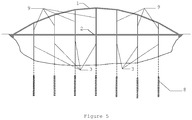
- Figure 1 shows the view of a first example of the present invention.
- An arch (1) supports inferiorly a deck (2) through columns (5), using ties (3), prestressed and connected to external anchorages located near the arch abutments.
- the deck has an internal expansion joint (4) and is horizontally supported at the ends by double supports (6).
- the ties (3) are anchored in the exterior and connected to deck nodes, possibly through some of the columns.
- antisymmetric loads For loads for which the arch has not anti-funicular shape, here generally designated "antisymmetric loads", the system behaves globally as a lightweight cable-tied structure, externally anchored or buttressed through the ties (3).
- the deck may be discontinuous with expansion joints (4) inside, so that through prestressing of the ties (3) mainly compression forces arise in the arch (1) and in the deck (2).
- the "horizontal" definitive connections of the deck to the exterior through the double support (6) are also favorable during construction, especially if the process is based on cantilevers growing from the abutments. Under the action of "antisymmetric loads” the system deforms activating the stiffness of the ties (3), pulling them on one side and compressing them on the other side. Deformations due to temperature variations and time dependent behavior of materials are accommodated by the expansion joint (4) inside.
- Figure 3 shows a view of an alternative example of the invention, with ties (3) approximately vertical and externally anchored.
- ties (3) approximately vertical and externally anchored.
- a double support (6) can be indispensable at one end of the deck.
- Figure 4 shows a view of an alternative example of the invention with ties (3) inclined and with external anchorages (8) concentrated in massive external blocks.
- ties (3) inclined and with external anchorages (8) concentrated in massive external blocks it is convenient to support the deck "horizontally" at one end with a double support (6) releasing the displacements at the other end with a single support (7) that accommodates the stretching and contraction of the deck.
- a double support (6) can be indispensable at one end of the deck.
- the mobilization of the stiffness of the ties (3), when inclined, either during application of prestressing, either due to balancing of "antisymmetric loads" is direct, without involving axial forces in the deck.
- the ties (3) can follow the alignments of the deck suspension elements (9).
- the system of ties (3) prestressed below the deck may have a reduced visual impact especially in the case of decks at low height.
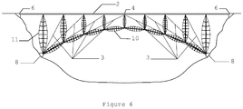
- FIG. 6 An alternative embodiment of the invention, with respect to a slender, articulated arch, is shown in Figure 6 and corresponds to a construction of arch segments (10) in the form of laterally braced slender struts, with possible prefabrication and later assembly, with controlled addition of stiffness through a system of ties (3) prestressed in any of the configurations of Figures 1 to 5 .
- the columns (11) may be built using elements similar to those of the arch segments (10) .
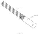
- the ties (3), prestressed may for example be composed of multiple strands of high strength steel, corresponding to independent modular anchorages (12), linked to the exterior by metallic parts (13), shown in Figure 7 , which may also serve as connections to other elements of the bridge.
- An example of application of the present invention corresponds to a road bridge, comprising an articulated arch with 250 m span and 40 m height, composed of segments (10) in form of prefabricated, laterally braced and prestressed stone ashlar struts.
- the deck (2) behaves as a continuous beam with spans of 31 m, with an expansion joint (4) inside and is supported by two parallel articulated ashlar stone arches, with rectangular cross section of 2.5 m wide by 0.6 m thick.
- Each of the ties (3) is inclined, comprising 4 cables of 12 or 16 prestressing steel strands, two in each arch.
- the cross section of the deck (2) corresponds to a box girder with 1.8 m of total height, an upper slab 14 m wide, a lower plate 7 m wide and two vertical webs.
Description
- The invention relates to the design and construction of bridges and other civil engineering structures, for roads, railways or other purposes, consisting of at least one arch and one deck.
- The arch may be made of any material, having any geometric shape, with a curved or polygonal axis and any cross section. The invention enables in particular the construction of bridges with slender arch and thin deck for large spans.
- It is considered slender any arch with a low ratio "Ia/La" between the inertia "Ia" of the cross section and the span "La", which can be zero in the case of an articulated arch with interior hinges. It is considered thin a deck with a low ratio between the inertia "Id" of its cross section and the arch span "La".
- In known concepts for arch bridges, high expenditures are necessary for obtaining bending stiffness of the arch or of the deck, to equilibrate external loads for which the arch has no anti-funicular shape. For large spans, the arch or the deck have large cross-sections, to resist the inherent high bending moments.
- The reduced bending stiffness of the slender arch and thin deck is compensated by controlled stiffness addition to the structure by means of prestressed ties, such as steel cables.
- The mobilization of the prestressed ties stiffness, in tension or relative compression, results in forces that directly balance the external loads, transmitting them to the foundations. On the other hand, the system of ties associated with the slender arch and the thin deck, enables equilibrium of loads for which the arch does not have anti-funicular shape, such as variable live loads.
- In the invention, the external anchored ties system is the main responsible for balancing of variable loads, so that the bending stiffness and strength of arch and deck can therefore be reduced.
- In the invention, the configuration of the ties system can be adjusted to the geometric available conditions, in particular to the relative position of arch and deck. The efficiency of the additional stiffness system increases with the verticality of the ties. The maximum efficiency corresponds to the vertical direct connection between the arch and the ground.
- The ties system configuration may imply axial forces in the deck. In order that those forces are compression only, intermediate expansion joints (4) may be adopted in the deck, which must be fixed longitudinally with double supports (6).
- The invention is characterized by controlled addition of stiffness to arch bridge structures, through permanent ties systems (3) prestressed between external anchorages (8) and the arch (1) or the deck (2), in order to mobilize reactions. The prestressed ties (3) can be arranged in different configurations, with inclined or vertical axis, connecting either the arch (1) or the deck (2) to the ground.
- The ties (3) are prestressed in order to remain tensioned under the effect of external actions, ensuring effective addition of stiffness both in tension and in relative compression.
- The stiffness of the ties system (3) depends on the area of the respective cross section and on the inclination of the respective axes. By increasing the verticality of the ties it is possible to increase the added stiffness without increasing the cross section.
- With the installation of ties system (3) it is possible to develop compressive forces in a slender symmetric arch, even for extreme cases of anti-symmetrical loading, since the deformation of the flexible arch is compatible with the activation of the ties (3) stiffness.
- The invention relates to an arch bridge structure according to
claim 1, with internal hinges, comprising portions articulated to each other, ensuring no bending by centering the compressive forces in the axis of the hinges. Such arch portions may be composed of slender straight elements under pure compression. It is possible to use prestressed and braced stonework slender struts. - The ties (3) inclined arrangement, between the deck and the external anchorages (8), causes axial forces in the deck. In the case such forces are of unfavorable traction, like in structural concrete decks, it is possible to reduce them using expansion joints (4) internally and double supports (6) in the ends of the deck, connecting it longitudinally to the abutments.
- The ties (3) vertical arrangement, prestressed between the arch and the ground, with external anchorages (8) distributed along the bridge, is a solution for direct transfer of vertical loads, through practically "invisible" "pillars". If the deck is suspended from the arch, the system of ties (3) anchored in the exterior, can follow the alignment of the suspension elements (9).
- The columns (5) between the arch and the deck may be continuous or have hinged connections at the ends, the latter being preferably.
- The known solutions of large span arch bridges have relatively thick arch cross sections, dimensioned to withstand high bending moments due to loads for which the arch shape is not anti-funicular.
- In known solutions of slender arch bridges, the equilibrium of loads for which the arch does not have anti-funicular shape causes significant bending in the deck, requiring a thick deck cross section. In this type of solution, the larger bending moments are located in the deck, which is less efficient than the arch to resist bending because it has lower permanent axial compression forces.
- Conventional solutions of slender arch and thick deck bridges are efficient for relatively small spans, up to about 40 meters, where the advantages of building a lightweight arch can justify the use of more rigid decks. For spans of that order of magnitude, the deck cross section that already has to be adequate to resist as a continuous beam over the columns, can be exploited without becoming disproportionately thick.
- For large span bridges with slender arch, the lower efficiency of the deck to equilibrate the variable live loads implies disproportionately large cross sections which make the arch effect relatively secondary.
- There are advantages in the construction of thin arches for large spans, not only for its lightweight but also because the reduced bending moments result in lower reinforcement in structural concrete solutions, even enabling ashlar or masonry solutions of natural stone. The reduced arch self weight allows the use of light gantries and facilitates piecewise prefabrication.
- Either in solutions of "thick arch and thin deck", either in solutions "thin arch and thick deck", the stiffness disproportion leads to arise of undesirable bending moments in the thinner element.
- In solutions with disproportionate bending stiffness distribution there are advantages in adopting as articulated the most flexible element. In this way, the bending moments in the thinner element can be eliminated. In arches made of brittle material, such as granite stone, the internal hinges can become indispensable.
- The use of prestressed ties (3) for load transfer can simultaneously reduce the cross sections of the arch and of the deck, resulting in overall lightweight solutions. The reduction of the arch and deck flexural stiffness allows a higher efficiency of the prestressed ties system (3), which would have to have greater cross section if the arch or the deck were stiffer.
- In known conceptions, it has been made use of diagonal ties systems between the deck and the arch, particularly during the construction phase, but with contrary inclination and different objectives than those of the present invention.
- In
figure 5 of "PatentDE 36 21 611 A1 (Prof. Dr.-Ing. Jörg Schlaich [DE]; Dipl.-Ing. Rudolf Bergermann [DE]) 14 January 1988", a solution related to the present invention is presented, in which the ties are not permanent and the arch has a non-negligible bending stiffness. The permanent and definitive nature of the ties (3) corresponds to a fundamental difference to the solution of said patent, which includes temporary cables during construction. The permanent ties (3) are essential to directly transfer the live loads and to stabilize the arch. The bridge behavior under service loading depends on the stiffness and prestressing of the permanent ties (3). The present invention makes possible the construction of an articulated arch, without the need of the deck bending stiffness. - In "Patent
CH 706 630 B1 - In "Klein P. et al., Cable Stayed Arch Bridge, Putrajaya, Kuala Lumpur, Malaysia, Structural Engineering International, IABSE, Zurich, CH, vol. 13, no. 3, 1 August 2003, pages 196-199", a solution is disclosed, in which the prestressing of the stayed cables does not increase the arch axial compression. In the present invention, the prestressing of the ties (3) increases permanently the axial compression force in the arch, which is advantageous for brittle materials like concrete.
-
-
Figure 1 shows a view of an arch bridge, in which (1) corresponds to the arch, (2) to the deck, (3) to a system of ties, prestressed and connected to external anchorages, (4) an internal expansion joint, (5) to columns supporting the deck on the arch, (6) to double supports in the ends of the deck, with prevented longitudinal displacements and (8) to external anchorages of ties (3). -
Figure 2 shows a view of an arch bridge, with alternative configuration of the ties (3) system, in which (1) corresponds to the arch, (2) to the deck, (3) to the ties, prestressed and connected to external anchorages, (5) to columns supporting the deck on the arch, (7) to simple supports with free longitudinal displacements, (8) to external anchorage of the ties (3) and (14) to systems of ties prestressed between the arc and the deck. -
Figure 3 : shows a view of an arch bridge, with alternative configuration for the ties (3) system, in which (1) corresponds to the arch, (2) to the deck, (3) to ties, "vertical", prestressed and connected to external anchorages, (5) to columns supporting the deck on the arch, (6) to double support, with prevented "horizontal" translation, (7) to simple support, with free "horizontal" translation and (8) to the external anchorages of the ties (3). -
Figure 4 shows a view of an arch bridge, with alternative configuration for the ties (3) system, in which (1) corresponds to the arch, (2) to the deck, (3) to ties, inclined, prestressed and connected to external anchorages, (5) to columns supporting the deck on the arch, (6) to double support, with prevented "horizontal" translation, (7) to simple support, with free "horizontal" translation and (8) to the external anchorages of the ties (3). -
Figure 5 shows a view of an alternative solution, in which (1) corresponds to the arch, (2) to the deck, suspended from the arch, (9) to deck suspension elements, (3) to ties, prestressed and connected to external anchorages, and (8) to the external anchorages of the ties (3). -
Figure 6 shows a view of an alternative solution, in which the arch is composed by laterally braced struts, similar to the columns over the arch, (2) corresponds to the deck, (3) to ties, inclined, prestressed and connected to external anchorages, (4) to an internal expansion joint, (6) to double support, with prevented "horizontal" translation, (10) to arch segments comprising slender laterally braced struts, and (11) to slender laterally braced columns. -
Figure 7 shows a detail of the end connection of a prestressed tie, in which (12) corresponds to independent modules of the tie and (13) to an anchorage part for the elementary ties and connection to other structural elements or to the exterior. -
Figure 1 shows the view of a first example of the present invention. An arch (1) supports inferiorly a deck (2) through columns (5), using ties (3), prestressed and connected to external anchorages located near the arch abutments. The deck has an internal expansion joint (4) and is horizontally supported at the ends by double supports (6). The ties (3) are anchored in the exterior and connected to deck nodes, possibly through some of the columns. For loads for which the arch has not anti-funicular shape, here generally designated "antisymmetric loads", the system behaves globally as a lightweight cable-tied structure, externally anchored or buttressed through the ties (3). The deck may be discontinuous with expansion joints (4) inside, so that through prestressing of the ties (3) mainly compression forces arise in the arch (1) and in the deck (2). The "horizontal" definitive connections of the deck to the exterior through the double support (6) are also favorable during construction, especially if the process is based on cantilevers growing from the abutments. Under the action of "antisymmetric loads" the system deforms activating the stiffness of the ties (3), pulling them on one side and compressing them on the other side. Deformations due to temperature variations and time dependent behavior of materials are accommodated by the expansion joint (4) inside. - For an alternative, shown in
Figure 2 , configuration of the ties (3), associated with systems of ties (14), inclined, prestressed and connecting the arch to the deck, it is appropriate to release the "horizontal" displacements in the simple supports (7) and dispense the expansion joints (4) inside. -
Figure 3 shows a view of an alternative example of the invention, with ties (3) approximately vertical and externally anchored. In this case it is convenient to support the deck "horizontally" at one end with a double support (6), while the other end can be movable, with a single support (7), accommodating the stretching and contraction of the deck. In cases where the columns (5) are hinged, a double support (6) can be indispensable at one end of the deck. The mobilization of the stiffness of the ties (3), when "vertical", either during application of prestressing, either due to balancing of "antisymmetric loads" is direct, without involving axial forces in the deck. -
Figure 4 shows a view of an alternative example of the invention with ties (3) inclined and with external anchorages (8) concentrated in massive external blocks. In this case it is convenient to support the deck "horizontally" at one end with a double support (6) releasing the displacements at the other end with a single support (7) that accommodates the stretching and contraction of the deck. In cases where the columns (5) have hinged ends, a double support (6) can be indispensable at one end of the deck. The mobilization of the stiffness of the ties (3), when inclined, either during application of prestressing, either due to balancing of "antisymmetric loads" is direct, without involving axial forces in the deck. - In the case of bridges with an arch (1) over the deck (2) (
Figure 5 ) or even in mixed solutions with the deck at intermediate arch levels, the ties (3) can follow the alignments of the deck suspension elements (9). The system of ties (3) prestressed below the deck may have a reduced visual impact especially in the case of decks at low height. - An alternative embodiment of the invention, with respect to a slender, articulated arch, is shown in
Figure 6 and corresponds to a construction of arch segments (10) in the form of laterally braced slender struts, with possible prefabrication and later assembly, with controlled addition of stiffness through a system of ties (3) prestressed in any of the configurations ofFigures 1 to 5 . The columns (11) may be built using elements similar to those of the arch segments (10) . - The ties (3), prestressed, may for example be composed of multiple strands of high strength steel, corresponding to independent modular anchorages (12), linked to the exterior by metallic parts (13), shown in
Figure 7 , which may also serve as connections to other elements of the bridge. - An example of application of the present invention corresponds to a road bridge, comprising an articulated arch with 250 m span and 40 m height, composed of segments (10) in form of prefabricated, laterally braced and prestressed stone ashlar struts. The deck (2) behaves as a continuous beam with spans of 31 m, with an expansion joint (4) inside and is supported by two parallel articulated ashlar stone arches, with rectangular cross section of 2.5 m wide by 0.6 m thick. Each of the ties (3) is inclined, comprising 4 cables of 12 or 16 prestressing steel strands, two in each arch. The cross section of the deck (2) corresponds to a box girder with 1.8 m of total height, an upper slab 14 m wide, a lower plate 7 m wide and two vertical webs.
Claims (13)
- Arch bridge structure, comprising a deck (2), an arch (1) with internal hinges, wherein said arch with internal hinges comprises portions articulated to each other, ensuring no bending by centering the compressive forces in the axis of the hinges, wherein the arch bridge structure further comprises permanent ties (3) prestressed between external lower anchorages (8) and upper anchorages at sections of the arch (1) or of the deck (2) for the controlled addition of stiffness to the structure, to mobilize reactions.
- Arch bridge structure according to claim 1, comprising ties (14) connected between the arch (1) and the deck (2) .
- Arch bridge structure according to claim 1, wherein the external anchorages (8) are located in the abutments of the arch (1).
- Arch bridge structure according to claim 1, wherein the external anchorages (8) are concentrated in two or more massive blocks located under the arch (1).
- Arch bridge structure according to claim 1, wherein the external anchorages (8) are distributed by multiple anchorage blocks located under the arch (1).
- Arch bridge structure according to claim 1, wherein the deck (2) is placed in a level superior to the arch (1).
- Arch bridge structure according to claim 1, wherein the deck (2) is placed in a level inferior to the arch (1).
- Arch bridge structure according to claim 1, wherein the deck (2) is placed in an intermediate level between the supports of the arch (1) and its upper section.
- Arch bridge structure according to claim 1, comprising an internal expansion joint (4) in the deck (2) and double supports (6) at the ends.
- Arch bridge structure according to claim 1, wherein the arch (1) is composed of struts (10) prestressed and braced.
- Arch bridge structure according to anyone of claims 1 to 10,
wherein the arch (1) and the deck (2) are in the same plane. - Arch bridge structure according to anyone of claims 1 to 10,
wherein the arch (1) or the deck (2) have a spatial axis. - Arch bridge structure according to anyone of claims 1 to 10,
wherein the arch (1) is non-symmetric.
Applications Claiming Priority (2)
| Application Number | Priority Date | Filing Date | Title |
|---|---|---|---|
| PT108710A PT108710A (en) | 2015-07-21 | 2015-07-21 | SYSTEM FOR ARC BRIDGE STRUCTURE, WITH MOBILIZATION OF EXTERIOR REACTIONS THROUGH DEFINITIVE STRETCHERS. |
| PCT/PT2016/050018 WO2017014660A1 (en) | 2015-07-21 | 2016-07-20 | Structural system for arch bridges, with mobilization of external reactions through definitive ties |
Publications (2)
| Publication Number | Publication Date |
|---|---|
| EP3325721A1 EP3325721A1 (en) | 2018-05-30 |
| EP3325721B1 true EP3325721B1 (en) | 2020-10-21 |
Family
ID=56894220
Family Applications (1)
| Application Number | Title | Priority Date | Filing Date |
|---|---|---|---|
| EP16763337.9A Active EP3325721B1 (en) | 2015-07-21 | 2016-07-20 | Structural system for arch bridges, with mobilization of external reactions through definitive ties |
Country Status (3)
| Country | Link |
|---|---|
| EP (1) | EP3325721B1 (en) |
| PT (1) | PT108710A (en) |
| WO (1) | WO2017014660A1 (en) |
Families Citing this family (11)
| Publication number | Priority date | Publication date | Assignee | Title |
|---|---|---|---|---|
| CN108086172A (en) * | 2017-12-19 | 2018-05-29 | 湖北省交通规划设计院股份有限公司 | A kind of method that spandrel arch bridge is reinforced using adjustment dead load thrust line |
| CN108166375A (en) * | 2018-01-11 | 2018-06-15 | 广西大学 | Arch bridge in advance |
| CN108416116B (en) * | 2018-02-09 | 2021-10-22 | 广西交通科学研究院有限公司 | Method for determining arch crown weight during arch springing enlarged section reinforcing parabolic arch |
| CN108460197B (en) * | 2018-02-09 | 2021-09-24 | 广西交通科学研究院有限公司 | Arch building disassembly and assembly scheme optimization method based on deformation amount control |
| CN108411760B (en) * | 2018-04-09 | 2023-10-03 | 广西大学 | Pull rod arch bridge |
| CN108547212A (en) * | 2018-07-02 | 2018-09-18 | 西北农林科技大学 | A kind of arch bridge structure that can prevent buckling deformation in arch rib face |
| CN108677682A (en) * | 2018-08-09 | 2018-10-19 | 广西大学 | Novel Deck Arch Bridges |
| CN110130233A (en) * | 2019-05-06 | 2019-08-16 | 中铁大桥(南京)桥隧诊治有限公司 | A kind of remodeling method suitable for double curvature arched bridge spandrel construction |
| CN112595499B (en) * | 2019-09-16 | 2023-07-25 | 深圳市建筑设计研究总院有限公司 | Pre-internal force calculation method of secondary self-internal force structure |
| CN111608084B (en) * | 2020-05-29 | 2022-03-29 | 中国铁建大桥工程局集团有限公司 | Integral prefabrication and assembly construction method for reinforced concrete arch bridge arch ring segments |
| CN113944095A (en) * | 2021-11-05 | 2022-01-18 | 上海市政工程设计研究总院(集团)有限公司 | Through tied arch bridge and construction method thereof |
Family Cites Families (3)
| Publication number | Priority date | Publication date | Assignee | Title |
|---|---|---|---|---|
| FR536858A (en) * | 1921-06-14 | 1922-05-11 | Construction process of reinforced concrete arches, without the use of formwork, hangers or scaffolding | |
| DE3621611A1 (en) * | 1986-06-27 | 1988-01-14 | Schlaich Joerg | Arched bridge and method for the construction thereof |
| CH706630B1 (en) * | 2013-05-14 | 2013-12-31 | S & P Clever Reinforcement Company Ag | Method for pretensioning steel structure e.g. iron bridge, involves vertically driving lifting element to polymer tapes in region between end anchorages for causing traction force tensioning between end regions of polymer tapes |
-
2015
- 2015-07-21 PT PT108710A patent/PT108710A/en unknown
-
2016
- 2016-07-20 WO PCT/PT2016/050018 patent/WO2017014660A1/en active Application Filing
- 2016-07-20 EP EP16763337.9A patent/EP3325721B1/en active Active
Non-Patent Citations (1)
| Title |
|---|
| None * |
Also Published As
| Publication number | Publication date |
|---|---|
| EP3325721A1 (en) | 2018-05-30 |
| WO2017014660A1 (en) | 2017-01-26 |
| PT108710A (en) | 2017-01-23 |
| WO2017014660A8 (en) | 2017-03-16 |
Similar Documents
| Publication | Publication Date | Title |
|---|---|---|
| EP3325721B1 (en) | Structural system for arch bridges, with mobilization of external reactions through definitive ties | |
| KR100536489B1 (en) | Manufacturing method for prestressed steel composite girder and prestressed steel composite girder thereby | |
| JP2004520511A (en) | Prestressed synthetic truss girder and method of manufacturing the same | |
| US7478450B2 (en) | Longitudinally offset bridge substructure support system | |
| KR100988074B1 (en) | Girder bridge connected to abutment and the construction method thereof | |
| KR100483083B1 (en) | Composite Deck having Frame and Concrete | |
| KR20120018565A (en) | Continuous supporting structure of corrugated steel web psc beam using secondary tendon and method for constructing the same | |
| KR101335382B1 (en) | Constrution method of Prestressed Composite Truss girder with internal hinge structure | |
| KR102035492B1 (en) | Semi cable stayed bridge structure | |
| KR101272278B1 (en) | Truss-arch type composite bridge | |
| KR101209674B1 (en) | The site built-up hybrid girder which is prestressed by gap difference of connection face of blocks | |
| JP4220295B2 (en) | Corrugated steel sheet web PC bridge closure method | |
| KR20020080931A (en) | building construction method using lattice typed cable structure in the plane | |
| KR102163560B1 (en) | Girdir and bridge having soundproof wall using the same | |
| JP2967874B1 (en) | How to build an overhead suspension bridge | |
| KR100974306B1 (en) | Bridge construction method using node structure hanged with girder | |
| KR101688517B1 (en) | Continuous bridge construction method using support pier girder and continuous tendon of pier | |
| JP2003138523A (en) | Construction method for tension string girder bridge | |
| CN107574747B (en) | Structure system of highway-railway co-construction multi-tower cable-stayed bridge | |
| JP4493245B2 (en) | Suspended floor slab bridge and method for reinforcing suspended floor slab | |
| GB2109040A (en) | Cable stayed bridge | |
| JP2004156343A (en) | Composite truss bridge and its construction method | |
| US1897470A (en) | Suspension bridge | |
| KR100437258B1 (en) | Rehabilitating method of rahman hinged-joint bridge | |
| KR20030012014A (en) | preflex bridge structure using plate girder system |
Legal Events
| Date | Code | Title | Description |
|---|---|---|---|
| STAA | Information on the status of an ep patent application or granted ep patent |
Free format text: STATUS: THE INTERNATIONAL PUBLICATION HAS BEEN MADE |
|
| PUAI | Public reference made under article 153(3) epc to a published international application that has entered the european phase |
Free format text: ORIGINAL CODE: 0009012 |
|
| STAA | Information on the status of an ep patent application or granted ep patent |
Free format text: STATUS: REQUEST FOR EXAMINATION WAS MADE |
|
| 17P | Request for examination filed |
Effective date: 20180119 |
|
| AK | Designated contracting states |
Kind code of ref document: A1 Designated state(s): AL AT BE BG CH CY CZ DE DK EE ES FI FR GB GR HR HU IE IS IT LI LT LU LV MC MK MT NL NO PL PT RO RS SE SI SK SM TR |
|
| AX | Request for extension of the european patent |
Extension state: BA ME |
|
| DAV | Request for validation of the european patent (deleted) | ||
| DAX | Request for extension of the european patent (deleted) | ||
| STAA | Information on the status of an ep patent application or granted ep patent |
Free format text: STATUS: EXAMINATION IS IN PROGRESS |
|
| 17Q | First examination report despatched |
Effective date: 20190823 |
|
| GRAP | Despatch of communication of intention to grant a patent |
Free format text: ORIGINAL CODE: EPIDOSNIGR1 |
|
| STAA | Information on the status of an ep patent application or granted ep patent |
Free format text: STATUS: GRANT OF PATENT IS INTENDED |
|
| INTG | Intention to grant announced |
Effective date: 20200515 |
|
| GRAS | Grant fee paid |
Free format text: ORIGINAL CODE: EPIDOSNIGR3 |
|
| GRAA | (expected) grant |
Free format text: ORIGINAL CODE: 0009210 |
|
| STAA | Information on the status of an ep patent application or granted ep patent |
Free format text: STATUS: THE PATENT HAS BEEN GRANTED |
|
| AK | Designated contracting states |
Kind code of ref document: B1 Designated state(s): AL AT BE BG CH CY CZ DE DK EE ES FI FR GB GR HR HU IE IS IT LI LT LU LV MC MK MT NL NO PL PT RO RS SE SI SK SM TR |
|
| REG | Reference to a national code |
Ref country code: GB Ref legal event code: FG4D |
|
| REG | Reference to a national code |
Ref country code: CH Ref legal event code: EP |
|
| REG | Reference to a national code |
Ref country code: DE Ref legal event code: R096 Ref document number: 602016046282 Country of ref document: DE |
|
| REG | Reference to a national code |
Ref country code: IE Ref legal event code: FG4D |
|
| REG | Reference to a national code |
Ref country code: AT Ref legal event code: REF Ref document number: 1325985 Country of ref document: AT Kind code of ref document: T Effective date: 20201115 |
|
| REG | Reference to a national code |
Ref country code: AT Ref legal event code: MK05 Ref document number: 1325985 Country of ref document: AT Kind code of ref document: T Effective date: 20201021 |
|
| REG | Reference to a national code |
Ref country code: NL Ref legal event code: MP Effective date: 20201021 |
|
| PG25 | Lapsed in a contracting state [announced via postgrant information from national office to epo] |
Ref country code: NO Free format text: LAPSE BECAUSE OF FAILURE TO SUBMIT A TRANSLATION OF THE DESCRIPTION OR TO PAY THE FEE WITHIN THE PRESCRIBED TIME-LIMIT Effective date: 20210121 Ref country code: PT Free format text: LAPSE BECAUSE OF FAILURE TO SUBMIT A TRANSLATION OF THE DESCRIPTION OR TO PAY THE FEE WITHIN THE PRESCRIBED TIME-LIMIT Effective date: 20210222 Ref country code: RS Free format text: LAPSE BECAUSE OF FAILURE TO SUBMIT A TRANSLATION OF THE DESCRIPTION OR TO PAY THE FEE WITHIN THE PRESCRIBED TIME-LIMIT Effective date: 20201021 Ref country code: FI Free format text: LAPSE BECAUSE OF FAILURE TO SUBMIT A TRANSLATION OF THE DESCRIPTION OR TO PAY THE FEE WITHIN THE PRESCRIBED TIME-LIMIT Effective date: 20201021 |
|
| REG | Reference to a national code |
Ref country code: LT Ref legal event code: MG4D |
|
| PG25 | Lapsed in a contracting state [announced via postgrant information from national office to epo] |
Ref country code: SE Free format text: LAPSE BECAUSE OF FAILURE TO SUBMIT A TRANSLATION OF THE DESCRIPTION OR TO PAY THE FEE WITHIN THE PRESCRIBED TIME-LIMIT Effective date: 20201021 Ref country code: AT Free format text: LAPSE BECAUSE OF FAILURE TO SUBMIT A TRANSLATION OF THE DESCRIPTION OR TO PAY THE FEE WITHIN THE PRESCRIBED TIME-LIMIT Effective date: 20201021 Ref country code: ES Free format text: LAPSE BECAUSE OF FAILURE TO SUBMIT A TRANSLATION OF THE DESCRIPTION OR TO PAY THE FEE WITHIN THE PRESCRIBED TIME-LIMIT Effective date: 20201021 Ref country code: BG Free format text: LAPSE BECAUSE OF FAILURE TO SUBMIT A TRANSLATION OF THE DESCRIPTION OR TO PAY THE FEE WITHIN THE PRESCRIBED TIME-LIMIT Effective date: 20210121 Ref country code: IS Free format text: LAPSE BECAUSE OF FAILURE TO SUBMIT A TRANSLATION OF THE DESCRIPTION OR TO PAY THE FEE WITHIN THE PRESCRIBED TIME-LIMIT Effective date: 20210221 Ref country code: LV Free format text: LAPSE BECAUSE OF FAILURE TO SUBMIT A TRANSLATION OF THE DESCRIPTION OR TO PAY THE FEE WITHIN THE PRESCRIBED TIME-LIMIT Effective date: 20201021 Ref country code: PL Free format text: LAPSE BECAUSE OF FAILURE TO SUBMIT A TRANSLATION OF THE DESCRIPTION OR TO PAY THE FEE WITHIN THE PRESCRIBED TIME-LIMIT Effective date: 20201021 |
|
| PG25 | Lapsed in a contracting state [announced via postgrant information from national office to epo] |
Ref country code: HR Free format text: LAPSE BECAUSE OF FAILURE TO SUBMIT A TRANSLATION OF THE DESCRIPTION OR TO PAY THE FEE WITHIN THE PRESCRIBED TIME-LIMIT Effective date: 20201021 Ref country code: NL Free format text: LAPSE BECAUSE OF FAILURE TO SUBMIT A TRANSLATION OF THE DESCRIPTION OR TO PAY THE FEE WITHIN THE PRESCRIBED TIME-LIMIT Effective date: 20201021 |
|
| REG | Reference to a national code |
Ref country code: DE Ref legal event code: R097 Ref document number: 602016046282 Country of ref document: DE |
|
| PG25 | Lapsed in a contracting state [announced via postgrant information from national office to epo] |
Ref country code: RO Free format text: LAPSE BECAUSE OF FAILURE TO SUBMIT A TRANSLATION OF THE DESCRIPTION OR TO PAY THE FEE WITHIN THE PRESCRIBED TIME-LIMIT Effective date: 20201021 Ref country code: SK Free format text: LAPSE BECAUSE OF FAILURE TO SUBMIT A TRANSLATION OF THE DESCRIPTION OR TO PAY THE FEE WITHIN THE PRESCRIBED TIME-LIMIT Effective date: 20201021 Ref country code: CZ Free format text: LAPSE BECAUSE OF FAILURE TO SUBMIT A TRANSLATION OF THE DESCRIPTION OR TO PAY THE FEE WITHIN THE PRESCRIBED TIME-LIMIT Effective date: 20201021 Ref country code: EE Free format text: LAPSE BECAUSE OF FAILURE TO SUBMIT A TRANSLATION OF THE DESCRIPTION OR TO PAY THE FEE WITHIN THE PRESCRIBED TIME-LIMIT Effective date: 20201021 Ref country code: SM Free format text: LAPSE BECAUSE OF FAILURE TO SUBMIT A TRANSLATION OF THE DESCRIPTION OR TO PAY THE FEE WITHIN THE PRESCRIBED TIME-LIMIT Effective date: 20201021 Ref country code: LT Free format text: LAPSE BECAUSE OF FAILURE TO SUBMIT A TRANSLATION OF THE DESCRIPTION OR TO PAY THE FEE WITHIN THE PRESCRIBED TIME-LIMIT Effective date: 20201021 |
|
| PLBE | No opposition filed within time limit |
Free format text: ORIGINAL CODE: 0009261 |
|
| STAA | Information on the status of an ep patent application or granted ep patent |
Free format text: STATUS: NO OPPOSITION FILED WITHIN TIME LIMIT |
|
| PG25 | Lapsed in a contracting state [announced via postgrant information from national office to epo] |
Ref country code: DK Free format text: LAPSE BECAUSE OF FAILURE TO SUBMIT A TRANSLATION OF THE DESCRIPTION OR TO PAY THE FEE WITHIN THE PRESCRIBED TIME-LIMIT Effective date: 20201021 |
|
| 26N | No opposition filed |
Effective date: 20210722 |
|
| PG25 | Lapsed in a contracting state [announced via postgrant information from national office to epo] |
Ref country code: IT Free format text: LAPSE BECAUSE OF FAILURE TO SUBMIT A TRANSLATION OF THE DESCRIPTION OR TO PAY THE FEE WITHIN THE PRESCRIBED TIME-LIMIT Effective date: 20201021 Ref country code: AL Free format text: LAPSE BECAUSE OF FAILURE TO SUBMIT A TRANSLATION OF THE DESCRIPTION OR TO PAY THE FEE WITHIN THE PRESCRIBED TIME-LIMIT Effective date: 20201021 |
|
| PG25 | Lapsed in a contracting state [announced via postgrant information from national office to epo] |
Ref country code: SI Free format text: LAPSE BECAUSE OF FAILURE TO SUBMIT A TRANSLATION OF THE DESCRIPTION OR TO PAY THE FEE WITHIN THE PRESCRIBED TIME-LIMIT Effective date: 20201021 |
|
| REG | Reference to a national code |
Ref country code: DE Ref legal event code: R119 Ref document number: 602016046282 Country of ref document: DE |
|
| REG | Reference to a national code |
Ref country code: CH Ref legal event code: PL |
|
| GBPC | Gb: european patent ceased through non-payment of renewal fee |
Effective date: 20210720 |
|
| PG25 | Lapsed in a contracting state [announced via postgrant information from national office to epo] |
Ref country code: MC Free format text: LAPSE BECAUSE OF FAILURE TO SUBMIT A TRANSLATION OF THE DESCRIPTION OR TO PAY THE FEE WITHIN THE PRESCRIBED TIME-LIMIT Effective date: 20201021 |
|
| REG | Reference to a national code |
Ref country code: BE Ref legal event code: MM Effective date: 20210731 |
|
| PG25 | Lapsed in a contracting state [announced via postgrant information from national office to epo] |
Ref country code: LI Free format text: LAPSE BECAUSE OF NON-PAYMENT OF DUE FEES Effective date: 20210731 Ref country code: GB Free format text: LAPSE BECAUSE OF NON-PAYMENT OF DUE FEES Effective date: 20210720 Ref country code: DE Free format text: LAPSE BECAUSE OF NON-PAYMENT OF DUE FEES Effective date: 20220201 Ref country code: CH Free format text: LAPSE BECAUSE OF NON-PAYMENT OF DUE FEES Effective date: 20210731 |
|
| PG25 | Lapsed in a contracting state [announced via postgrant information from national office to epo] |
Ref country code: IS Free format text: LAPSE BECAUSE OF FAILURE TO SUBMIT A TRANSLATION OF THE DESCRIPTION OR TO PAY THE FEE WITHIN THE PRESCRIBED TIME-LIMIT Effective date: 20210221 Ref country code: LU Free format text: LAPSE BECAUSE OF NON-PAYMENT OF DUE FEES Effective date: 20210720 Ref country code: FR Free format text: LAPSE BECAUSE OF NON-PAYMENT OF DUE FEES Effective date: 20210731 |
|
| PG25 | Lapsed in a contracting state [announced via postgrant information from national office to epo] |
Ref country code: IE Free format text: LAPSE BECAUSE OF NON-PAYMENT OF DUE FEES Effective date: 20210720 Ref country code: BE Free format text: LAPSE BECAUSE OF NON-PAYMENT OF DUE FEES Effective date: 20210731 |
|
| PG25 | Lapsed in a contracting state [announced via postgrant information from national office to epo] |
Ref country code: HU Free format text: LAPSE BECAUSE OF FAILURE TO SUBMIT A TRANSLATION OF THE DESCRIPTION OR TO PAY THE FEE WITHIN THE PRESCRIBED TIME-LIMIT; INVALID AB INITIO Effective date: 20160720 |
|
| PG25 | Lapsed in a contracting state [announced via postgrant information from national office to epo] |
Ref country code: CY Free format text: LAPSE BECAUSE OF FAILURE TO SUBMIT A TRANSLATION OF THE DESCRIPTION OR TO PAY THE FEE WITHIN THE PRESCRIBED TIME-LIMIT Effective date: 20201021 |
|
| PG25 | Lapsed in a contracting state [announced via postgrant information from national office to epo] |
Ref country code: GR Free format text: LAPSE BECAUSE OF FAILURE TO SUBMIT A TRANSLATION OF THE DESCRIPTION OR TO PAY THE FEE WITHIN THE PRESCRIBED TIME-LIMIT Effective date: 20201021 |