EP3325580B1 - Gaskonditionierungsverfahren und system zum extrahieren eines kondensierbaren dampfes aus einem zugeführten gas - Google Patents
Gaskonditionierungsverfahren und system zum extrahieren eines kondensierbaren dampfes aus einem zugeführten gas Download PDFInfo
- Publication number
- EP3325580B1 EP3325580B1 EP16744463.7A EP16744463A EP3325580B1 EP 3325580 B1 EP3325580 B1 EP 3325580B1 EP 16744463 A EP16744463 A EP 16744463A EP 3325580 B1 EP3325580 B1 EP 3325580B1
- Authority
- EP
- European Patent Office
- Prior art keywords
- gas
- condensing
- temperature
- location
- condensed fraction
- Prior art date
- Legal status (The legal status is an assumption and is not a legal conclusion. Google has not performed a legal analysis and makes no representation as to the accuracy of the status listed.)
- Active
Links
Images


Classifications
-
- C—CHEMISTRY; METALLURGY
- C10—PETROLEUM, GAS OR COKE INDUSTRIES; TECHNICAL GASES CONTAINING CARBON MONOXIDE; FUELS; LUBRICANTS; PEAT
- C10K—PURIFYING OR MODIFYING THE CHEMICAL COMPOSITION OF COMBUSTIBLE GASES CONTAINING CARBON MONOXIDE
- C10K1/00—Purifying combustible gases containing carbon monoxide
- C10K1/04—Purifying combustible gases containing carbon monoxide by cooling to condense non-gaseous materials
-
- B—PERFORMING OPERATIONS; TRANSPORTING
- B01—PHYSICAL OR CHEMICAL PROCESSES OR APPARATUS IN GENERAL
- B01D—SEPARATION
- B01D5/00—Condensation of vapours; Recovering volatile solvents by condensation
-
- B—PERFORMING OPERATIONS; TRANSPORTING
- B01—PHYSICAL OR CHEMICAL PROCESSES OR APPARATUS IN GENERAL
- B01D—SEPARATION
- B01D5/00—Condensation of vapours; Recovering volatile solvents by condensation
- B01D5/0078—Condensation of vapours; Recovering volatile solvents by condensation characterised by auxiliary systems or arrangements
- B01D5/009—Collecting, removing and/or treatment of the condensate
-
- C—CHEMISTRY; METALLURGY
- C10—PETROLEUM, GAS OR COKE INDUSTRIES; TECHNICAL GASES CONTAINING CARBON MONOXIDE; FUELS; LUBRICANTS; PEAT
- C10G—CRACKING HYDROCARBON OILS; PRODUCTION OF LIQUID HYDROCARBON MIXTURES, e.g. BY DESTRUCTIVE HYDROGENATION, OLIGOMERISATION, POLYMERISATION; RECOVERY OF HYDROCARBON OILS FROM OIL-SHALE, OIL-SAND, OR GASES; REFINING MIXTURES MAINLY CONSISTING OF HYDROCARBONS; REFORMING OF NAPHTHA; MINERAL WAXES
- C10G70/00—Working-up undefined normally gaseous mixtures obtained by processes covered by groups C10G9/00, C10G11/00, C10G15/00, C10G47/00, C10G51/00
- C10G70/04—Working-up undefined normally gaseous mixtures obtained by processes covered by groups C10G9/00, C10G11/00, C10G15/00, C10G47/00, C10G51/00 by physical processes
- C10G70/043—Working-up undefined normally gaseous mixtures obtained by processes covered by groups C10G9/00, C10G11/00, C10G15/00, C10G47/00, C10G51/00 by physical processes by fractional condensation
-
- C—CHEMISTRY; METALLURGY
- C10—PETROLEUM, GAS OR COKE INDUSTRIES; TECHNICAL GASES CONTAINING CARBON MONOXIDE; FUELS; LUBRICANTS; PEAT
- C10K—PURIFYING OR MODIFYING THE CHEMICAL COMPOSITION OF COMBUSTIBLE GASES CONTAINING CARBON MONOXIDE
- C10K1/00—Purifying combustible gases containing carbon monoxide
- C10K1/02—Dust removal
- C10K1/024—Dust removal by filtration
-
- C—CHEMISTRY; METALLURGY
- C10—PETROLEUM, GAS OR COKE INDUSTRIES; TECHNICAL GASES CONTAINING CARBON MONOXIDE; FUELS; LUBRICANTS; PEAT
- C10K—PURIFYING OR MODIFYING THE CHEMICAL COMPOSITION OF COMBUSTIBLE GASES CONTAINING CARBON MONOXIDE
- C10K1/00—Purifying combustible gases containing carbon monoxide
- C10K1/04—Purifying combustible gases containing carbon monoxide by cooling to condense non-gaseous materials
- C10K1/046—Reducing the tar content
-
- C—CHEMISTRY; METALLURGY
- C10—PETROLEUM, GAS OR COKE INDUSTRIES; TECHNICAL GASES CONTAINING CARBON MONOXIDE; FUELS; LUBRICANTS; PEAT
- C10L—FUELS NOT OTHERWISE PROVIDED FOR; NATURAL GAS; SYNTHETIC NATURAL GAS OBTAINED BY PROCESSES NOT COVERED BY SUBCLASSES C10G OR C10K; LIQUIFIED PETROLEUM GAS; USE OF ADDITIVES TO FUELS OR FIRES; FIRE-LIGHTERS
- C10L3/00—Gaseous fuels; Natural gas; Synthetic natural gas obtained by processes not covered by subclass C10G, C10K; Liquefied petroleum gas
- C10L3/06—Natural gas; Synthetic natural gas obtained by processes not covered by C10G, C10K3/02 or C10K3/04
- C10L3/10—Working-up natural gas or synthetic natural gas
- C10L3/101—Removal of contaminants
-
- F—MECHANICAL ENGINEERING; LIGHTING; HEATING; WEAPONS; BLASTING
- F28—HEAT EXCHANGE IN GENERAL
- F28B—STEAM OR VAPOUR CONDENSERS
- F28B1/00—Condensers in which the steam or vapour is separate from the cooling medium by walls, e.g. surface condenser
-
- F—MECHANICAL ENGINEERING; LIGHTING; HEATING; WEAPONS; BLASTING
- F28—HEAT EXCHANGE IN GENERAL
- F28B—STEAM OR VAPOUR CONDENSERS
- F28B11/00—Controlling arrangements with features specially adapted for condensers
-
- F—MECHANICAL ENGINEERING; LIGHTING; HEATING; WEAPONS; BLASTING
- F28—HEAT EXCHANGE IN GENERAL
- F28B—STEAM OR VAPOUR CONDENSERS
- F28B7/00—Combinations of two or more condensers, e.g. provision of reserve condenser
-
- F—MECHANICAL ENGINEERING; LIGHTING; HEATING; WEAPONS; BLASTING
- F28—HEAT EXCHANGE IN GENERAL
- F28B—STEAM OR VAPOUR CONDENSERS
- F28B9/00—Auxiliary systems, arrangements, or devices
- F28B9/08—Auxiliary systems, arrangements, or devices for collecting and removing condensate
-
- F—MECHANICAL ENGINEERING; LIGHTING; HEATING; WEAPONS; BLASTING
- F28—HEAT EXCHANGE IN GENERAL
- F28D—HEAT-EXCHANGE APPARATUS, NOT PROVIDED FOR IN ANOTHER SUBCLASS, IN WHICH THE HEAT-EXCHANGE MEDIA DO NOT COME INTO DIRECT CONTACT
- F28D1/00—Heat-exchange apparatus having stationary conduit assemblies for one heat-exchange medium only, the media being in contact with different sides of the conduit wall, in which the other heat-exchange medium is a large body of fluid, e.g. domestic or motor car radiators
- F28D1/06—Heat-exchange apparatus having stationary conduit assemblies for one heat-exchange medium only, the media being in contact with different sides of the conduit wall, in which the other heat-exchange medium is a large body of fluid, e.g. domestic or motor car radiators with the heat-exchange conduits forming part of, or being attached to, the tank containing the body of fluid
-
- F—MECHANICAL ENGINEERING; LIGHTING; HEATING; WEAPONS; BLASTING
- F28—HEAT EXCHANGE IN GENERAL
- F28D—HEAT-EXCHANGE APPARATUS, NOT PROVIDED FOR IN ANOTHER SUBCLASS, IN WHICH THE HEAT-EXCHANGE MEDIA DO NOT COME INTO DIRECT CONTACT
- F28D7/00—Heat-exchange apparatus having stationary tubular conduit assemblies for both heat-exchange media, the media being in contact with different sides of a conduit wall
- F28D7/06—Heat-exchange apparatus having stationary tubular conduit assemblies for both heat-exchange media, the media being in contact with different sides of a conduit wall the conduits having a single U-bend
-
- F—MECHANICAL ENGINEERING; LIGHTING; HEATING; WEAPONS; BLASTING
- F28—HEAT EXCHANGE IN GENERAL
- F28D—HEAT-EXCHANGE APPARATUS, NOT PROVIDED FOR IN ANOTHER SUBCLASS, IN WHICH THE HEAT-EXCHANGE MEDIA DO NOT COME INTO DIRECT CONTACT
- F28D7/00—Heat-exchange apparatus having stationary tubular conduit assemblies for both heat-exchange media, the media being in contact with different sides of a conduit wall
- F28D7/16—Heat-exchange apparatus having stationary tubular conduit assemblies for both heat-exchange media, the media being in contact with different sides of a conduit wall the conduits being arranged in parallel spaced relation
-
- F—MECHANICAL ENGINEERING; LIGHTING; HEATING; WEAPONS; BLASTING
- F28—HEAT EXCHANGE IN GENERAL
- F28F—DETAILS OF HEAT-EXCHANGE AND HEAT-TRANSFER APPARATUS, OF GENERAL APPLICATION
- F28F1/00—Tubular elements; Assemblies of tubular elements
- F28F1/10—Tubular elements and assemblies thereof with means for increasing heat-transfer area, e.g. with fins, with projections, with recesses
- F28F1/12—Tubular elements and assemblies thereof with means for increasing heat-transfer area, e.g. with fins, with projections, with recesses the means being only outside the tubular element
- F28F1/34—Tubular elements and assemblies thereof with means for increasing heat-transfer area, e.g. with fins, with projections, with recesses the means being only outside the tubular element and extending obliquely
- F28F1/36—Tubular elements and assemblies thereof with means for increasing heat-transfer area, e.g. with fins, with projections, with recesses the means being only outside the tubular element and extending obliquely the means being helically wound fins or wire spirals
-
- F—MECHANICAL ENGINEERING; LIGHTING; HEATING; WEAPONS; BLASTING
- F28—HEAT EXCHANGE IN GENERAL
- F28F—DETAILS OF HEAT-EXCHANGE AND HEAT-TRANSFER APPARATUS, OF GENERAL APPLICATION
- F28F13/00—Arrangements for modifying heat-transfer, e.g. increasing, decreasing
- F28F13/18—Arrangements for modifying heat-transfer, e.g. increasing, decreasing by applying coatings, e.g. radiation-absorbing, radiation-reflecting; by surface treatment, e.g. polishing
- F28F13/182—Arrangements for modifying heat-transfer, e.g. increasing, decreasing by applying coatings, e.g. radiation-absorbing, radiation-reflecting; by surface treatment, e.g. polishing especially adapted for evaporator or condenser surfaces
-
- F—MECHANICAL ENGINEERING; LIGHTING; HEATING; WEAPONS; BLASTING
- F28—HEAT EXCHANGE IN GENERAL
- F28F—DETAILS OF HEAT-EXCHANGE AND HEAT-TRANSFER APPARATUS, OF GENERAL APPLICATION
- F28F19/00—Preventing the formation of deposits or corrosion, e.g. by using filters or scrapers
- F28F19/008—Preventing the formation of deposits or corrosion, e.g. by using filters or scrapers by using scrapers
-
- F—MECHANICAL ENGINEERING; LIGHTING; HEATING; WEAPONS; BLASTING
- F28—HEAT EXCHANGE IN GENERAL
- F28G—CLEANING OF INTERNAL OR EXTERNAL SURFACES OF HEAT-EXCHANGE OR HEAT-TRANSFER CONDUITS, e.g. WATER TUBES OR BOILERS
- F28G3/00—Rotary appliances
- F28G3/10—Rotary appliances having scrapers, hammers, or cutters, e.g. rigidly mounted
- F28G3/12—Rotary appliances having scrapers, hammers, or cutters, e.g. rigidly mounted resiliently mounted
-
- C—CHEMISTRY; METALLURGY
- C10—PETROLEUM, GAS OR COKE INDUSTRIES; TECHNICAL GASES CONTAINING CARBON MONOXIDE; FUELS; LUBRICANTS; PEAT
- C10G—CRACKING HYDROCARBON OILS; PRODUCTION OF LIQUID HYDROCARBON MIXTURES, e.g. BY DESTRUCTIVE HYDROGENATION, OLIGOMERISATION, POLYMERISATION; RECOVERY OF HYDROCARBON OILS FROM OIL-SHALE, OIL-SAND, OR GASES; REFINING MIXTURES MAINLY CONSISTING OF HYDROCARBONS; REFORMING OF NAPHTHA; MINERAL WAXES
- C10G2300/00—Aspects relating to hydrocarbon processing covered by groups C10G1/00 - C10G99/00
- C10G2300/40—Characteristics of the process deviating from typical ways of processing
- C10G2300/4006—Temperature
-
- F—MECHANICAL ENGINEERING; LIGHTING; HEATING; WEAPONS; BLASTING
- F28—HEAT EXCHANGE IN GENERAL
- F28F—DETAILS OF HEAT-EXCHANGE AND HEAT-TRANSFER APPARATUS, OF GENERAL APPLICATION
- F28F9/00—Casings; Header boxes; Auxiliary supports for elements; Auxiliary members within casings
- F28F9/22—Arrangements for directing heat-exchange media into successive compartments, e.g. arrangements of guide plates
- F28F2009/222—Particular guide plates, baffles or deflectors, e.g. having particular orientation relative to an elongated casing or conduit
- F28F2009/228—Oblique partitions
Definitions
- the invention relates to the field of gas conditioning and is particularly, although not exclusively, applicable to conditioning gases produced through gasification ("gasification gas").
- Gasification gas is a product of gasification, for example coal gasification and pyrolysis of carbonaceous feeds.
- gas produced by pyrolysing and methanating a biomass feed i.e. a methane based fuel gas
- methane based fuel gas is considered to be a source of renewable energy and thus it offers a promising solution in achieving carbon neutrality for the processing industries.
- its high methane content makes it ideal for fueling generators and gas engines where its lean-burn characteristic is favorable for meeting emission requirements.
- the gas extracted from the chambers often carries vaporised long chain hydrocarbons such as tars, as well as other impurities that need to be stripped from the fuel gas before it can be used.
- tars vaporised long chain hydrocarbons
- the presence of tars in fuel gas reduces its purity, and in some cases, i.e. gas engine applications, leads to inefficiencies, uncontrolled emissions and internal fouling.
- the tars may be directly condensed out of the fuel gas without the use of scrubber solution.
- KR20110137977 (Korean Institute of Energy Research) teaches a centrifugal condenser where fuel gas flowing through a revolving annulus are continuously cooled by the surrounding cooling fluids. On cooling the vaporised tars are condensed out of the fuel gas and flow along an angled wall before leaving the annulus at a liquid exit with the aid of centrifugal force, leaving a stream of conditioned and purified gas to be purged at a gas exit.
- processing temperature greatly affects tar viscosity and so inadequate control of the cooling temperature, i.e.
- overcooling may lead to thickened tars and thus blockage at the liquid exit, i.e. the centrifugal force imparted by the revolving annulus may not be sufficient to expel the thickened tars out of the revolving annulus.
- Tars are long chain hydrocarbons that are the condensable fractions in process gases created by industrial processes. Typically tars with larger molecular weights have higher dew points. These tars typically consist of many aromatic rings for example heavy polyaromatic hydrocarbons. Tars with lower molecular weights, often with fewer aromatic rings, usually have lower dew points. In general tars with higher dew points will have higher viscosities at a specific temperature than those with lower dew points. When in mixture these tars can form a viscous paste which is undesirable and problematic in any gas treatment process. Using the system taught in KR20110137977 for tar removal would inevitably result in great inconsistency in viscosity, which affects heat transfer and drainage performance. For example, in KR20110137977 where the coolant is supplied at a single cooling temperature, the tar mixture containing tars with high dew points significantly thicken the overall mixture, preventing effective draining.
- a gas conditioning unit that is able to efficiently and reliably remove tars from a gasification gas / fuel gas is highly desirable.
- WO 2008/058137 A2 depicts methods and systems for substantially continuously treating comminuted material containing carbon and hydrogen.
- WO 2008/110834 A1 depicts a gasification reactor which comprises a wiper system.
- the supplied gas is typically (but not necessarily) a product of coal gasification or pyrolysis of a carbonaceous feeds.
- it comprises methane, as well as condensable hydrocarbon vapor, e.g. tar, having a non-gaseous phase at a standard ambient temperature and pressure, i.e. at 25°C and 1atm.
- the supplied gas, at a feed temperature exceeding the dew point of condensable vapour, is typically a well-mixed gas.
- a mechanical scraping means for example a scraper, the condensed tar may be removed in a timely manner to improve heat transfer at the condensing surface, i.e.
- the mechanical scraping means also allows the efficient discharge of tar with higher viscosity, i.e. tar with paste like consistencies; this improves process reliability.
- a thermally controlled conveying means may be provided for heating and/or vaporising the condensed fraction to improve its flowability.
- the condensed fraction may be vapourised to form a concentrated condensable vapor, i.e. a gaseous mixture having a substantially higher tar concentration than the supplied gas.
- Step ii) may be repeated at further condensing surfaces using the product gas of the previous step as an input gas.
- the process can be described as condensing and removing the condensable vapour, or tars, in sequential stages.
- the mixture of tars removed in each of the stages are of similar dew point and viscosity, and as a result reduces process difficulties.
- the preliminary fraction has a higher dew point temperature than the subsequent fraction such that the preliminary fraction has a higher viscosity than the subsequent fraction at any given temperature below the second temperature.
- Steps c)-d) may be repeated at further locations using a condensed fraction from a further condensing surface and/or the heated condensed fraction of the previous step as input material, in order to form more concentrated condensable vapour.
- the process may comprises a further location to heat and vapourise any condensed fraction that remains in the liquid phase. The process can therefore be described as heating and vapourising the condensed fractions, in sequential stages, to form a concentrated condensable vapour.
- the supplied gas is conditioned prior to the condensable vapour removal process.
- the process may further comprise a step of controlling supplied gas temperature with a supplied gas heat exchanger, as well as a step of filtering with the use of a filter, so that the supplied gas is free from any condensed fractions and particulates.
- the product gas is scrubbed with the use of a scrubber to remove any outstanding contaminants.
- the scrubbed product gas is dried using a gas dryer so to increase the calorific value of the gas.
- a system for carrying out the process comprising at least one condensing unit and (optionally) a thermally controlled conveying means provided for heating and/or vaporizing the at least one condensed fraction removed from the at least one condensing unit to form the concentrated condensable vapour, as such their viscosity may be maintained or reduced to improve flowability; and wherein the thermally controlled conveying means is a heating extruder or a heating scraped surface heat exchanger, or in some cases batch heaters.
- the at least one condensing unit comprises the first condensing surface and the second condensing surface, with mechanical scraping means for removing condensed fractions from each condensing surface; each of the first condensing surface and the second condensing surface are individually temperature controlled.
- the condensing unit is an extruder, but it can be any heat exchanger comprising a mechanical scraping means known to the person skilled in the art, for example scraped surface heat exchangers.
- the system may be a single jacketed extruder wherein the jacket may be sectioned to provide first and second temperatures along its length.
- the system may instead comprise at least two condensing units that are connected; wherein each of the at least two condensing units are individually temperature controlled; in this case a first condensing unit serves as the first condensing surface and a second condensing unit serves as the second condensing surface.
- each of the jackets of the at least two condensing units may further comprise partitions to provide several cooling temperatures to increase flexibility.
- the thermally controlled conveying means comprises the first location, second location and third location for heating and vaporising the condensed fraction removed from the each of the condensing units.
- the first location, second location and third location are sequentially connected; the temperature increases progressively from the first location to the third location.
- the first location, second location and third location may be different sections along a thermally sectioned extruder or scraped surface heat exchanger, or alternatively they can be discreet units in serial connection.
- the extruder may comprise one or more helical screws for scraping any condensed fraction off the cooled barrels walls, as well as conveying said fractions for removal.
- the extruder may comprise two screws for an increased heat transfer area and enlarged gas flow path, but it may comprise of any number of screws as required.
- the helical screws may comprise a non-stick coating for efficient discharge of condensed fraction from their surface.
- the screws may be temperature controlled for an increased cooling area; for example the screws may be cooled by internal coolant circulation, or with Peltier cooler or any other cooling means.
- the condensing unit is a scraped surface heat exchanger comprising mechanical scraping means for scraping and conveying the at least one condensed fraction.
- the mechanical scraping means comprises one or more pistons or scraper; wherein the scraped surface heat exchanger comprises a barrel enclosed in a heating/cooling jackets to provide temperature control.
- the piston or scraper oscillates reciprocally in the axial direction where any condensed tars are scraped and removed at a contacting surface.
- the contacting surfaces between the one or more piston or scraper and the barrel comprising a thermally conductive and hard-wearing coating for protecting said contacting surface;
- the hard-wearing coating may be boron nitride or any other suitable coatings known to the person skilled in the art.
- the extruder comprises gas/liquid separation means for separating any entrained preliminary fraction/ subsequent fraction from the process gas/product gas; said separation means may be gravity separator, centrifuges, cyclone, filters or any other means known to the person in the art.
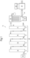
- the gas conditioning system 10 is configured primarily for purifying gasification gas or fuel gas generated by an external pyrolysis process in order to produce a high purity fuel gas ready for use in gas engines or turbines, or as a direct fuel source or any other suitable uses.
- the gas conditioning system 10 is also suitable for purifying gasification gas or fuel gas produced by other processes such as coal gasification, biomass gasification or even natural gas recovered in the oil and gas industries prior to liquefying.
- the gas conditioning system 10 comprises a heat exchanger 20 for preheating or cooling an incoming fuel gas, a high temperature particulate filter (HTPF) 30 for filtering suspended particulates prior to entering a condenser module 40, where vaporised tars and other heavy hydrocarbons are condensed and stripped from the fuel gas.
- HTPF high temperature particulate filter
- the purified gas is passed through a scrubbing system 90 to remove any remaining impurities that are not captured by the HTPF 30 and condenser module 40.
- the product gas, collected at the outlet of the scrubbing system 90 may fuel gas engines and generators directly or it can be pressurised or liquefied for storage and transportation.
- the condenser module 40 is scalable, and comprises at least one condensing unit 41.
- a number of additional units 42,43,44, as shown in the particular embodiment in Figure 1 may be included.
- the required number of additional units, as well as their sizes and operating conditions, depend upon the process parameters and the condition of incoming gas, i.e. its throughput and temperature, as well as the tars composition and concentration.
- the illustrated example in Figure 1 features a condenser module 40 configured for extracting tars from a fuel gas produced by a pyrolysis / methanation reactor comprising methane, tars, other non-condensable hydrocarbons, CO, CO 2 , H 2 and other trace gaseous components.
- the gas stream exits the pyrolysis / methanation reactor at a temperature of approximately 800°C before passing through a heat exchanger 20 for cooling the gas to approximately 550°C; the outlet temperature is significantly higher than the dew point of vaporised tars to ensure the majority of tars are kept in a gas phase.
- the outlet temperature of the heat exchanger 20 may be adjusted according to the dew point of the vaporised tars, which varies due to a number of factors such as tars concentration and process pressure.
- the heat exchanger 20 further comprises a cooler 22 for dissipating any extracted heat from the passing hot gas.
- the cooler 22 supplies a flow of coolant to the heat exchanger 20, i.e. chill water, glycol/water mixture or air, or it can be any other suitable coolant or gases.
- the heat exchanger 20 may be a plate-fin heat exchanger but it can be any non-direct contact heat exchanger known to the person skilled in the art, for example plate heat exchangers and cross flow heat exchangers.
- the inner walls of the heat exchanger, i.e. the gas flow passage may optionally be constructed with a high nickel content alloy to allow catalytic cracking of tars under the prescribed temperature, i.e. in the range of 550°C to 800°C.
- the high nickel content alloy may be Inconel 617, Nickel Alloy 230 or any nickel containing alloy with suitable thermal, catalytic, and anti-corrosive properties.
- the cooled gas exiting the heat exchanger passes through the high temperature particulate filtration unit 30 to remove particulate matters suspended within.
- the HTPF is a ceramic filter but it can be any suitable filter known to the person skilled in the art.
- the mesh size of the filter depends upon the size of particulate and should not induce a significant pressure drop.
- the filtration unit 30, along with all the pipelines / ducts featured elsewhere in the gas conditioning unit 10 are adequately insulated to minimise heat loss and thus uncontrolled condensation of tars. Since the gas is kept at a temperature well above the dew point of tars, the filtration unit 30 is prevented from extracting any tars at this stage.
- the filtration unit 30 may comprise of an automated backflush system where heated product gas is injected to blast on and displace any captured particulates from the filtration unit 30 to a dropout point; said backflush system is a continuous process commonly used within high temperature filtration.
- the automated backflush system may also comprise a mechanical wiper or any other mechanisms known to the person skilled in the art.
- the filtered particulate is readily removed at collection point 32 for disposal.
- the filtered gas 34 Upon exiting the HTPF 30 the filtered gas 34 enters the condenser module 40, which in the illustrated example in Figure 1 consists of four serially connected individual condensing units 41,42,43,44. Said condensing units 41,42,43,44 may be exact replicas of each other, or they may be sized differently according to process conditions. As discussed, tars produced by the pyrolysis process consist of different types of tars all having different dew points and viscosity, and therefore processing all the tars at a uniform temperature would result in processing difficulties.
- serially connected condensing units have gradually decreasing gas outlet temperatures, thus together they sequentially cool a passing gas and allow mixtures of tars with similar dew points and flow viscosities to condense and be extracted from a given unit.
- the number of condensing units required in a condenser module 40 and the outlet temperatures in each of the condensing units depends upon a number of factors, for example gas throughput, pressure, heat transfer efficiencies in condensing units, as well as the tars composition and concentration which in turn relates to the throughput and type of feedstock provided for upstream pyrolysis process.
- the gas is cooled from 550°C to 400°C at the first condenser unit 41, from 400°C to 250°C at the second condenser unit 42, from 250°C to 100°C for the third condenser unit 43 and from 100°C to 60°C for the final condenser unit 44.
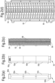
- the condensing units 41,42,43,44 may be vertically mounted twin screw extruders enclosed by a cooling jacket 52.
- the condensing unit 50 can be any dynamic heat exchanger with mechanical scraping means for the condensed tars, for example, single or multiple screw extruders and scraped surface heat exchangers.
- the gas enters the extruder through gas inlet 50a where a lowered temperature causes vaporised tars to condense and deposit onto the inner surfaces of the barrel 54.
- the condensed tars are then mechanically conveyed toward the extraction port 58 at the end of the barrel 54 by the screw flights 56.
- the gas exits the extruder through gas outlet 50b.
- the vertical configuration also helps to drain any condensed tars by gravity.
- the condensed tars are maintained at a fluid and drainable state by controlling the coolant temperature.
- the condensing unit 50 contains two shafted self-wiping auger screws 56 where the angle, pitch and rotation speed are determined according to process conditions, to allow sufficient gas/wall contact area, as well as turbulence in the gas flow so to promote heat transfer at the cooling barrel walls, yet to minimise flow resistance that would otherwise lead to pressure drop.
- hollow screw shaft and flights are employed for circulating a coolant within; this greatly increases heat transfer area and as a result the condensing unit 50 may be constructed to a more compacted size.
- the screw flights scrapes along the barrel walls, wiping any condensed tars from the surface of barrel walls, as such enhances heat transfer efficiency.
- the tars are conveyed mechanically towards the extraction port 58 located at the lowest point of the condensing unit 50.
- the surface of the screw flights is coated with a formulated non-stick layer stable at the relevant process temperature so that any condensed tars may be drained effectively from the screw flights.
- the formulated non-stick coating are Teflon, enamel coatings, hard chrome or any other technical chromium, ceramic, polymer composite, Electroless Nickel/Polymer composite, thermal spray/polymer composite or any other coatings known the person skilled in the art.
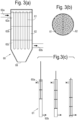
- condensing module 40 may additionally comprise vertically mounted scraped surface heat exchangers (SSHE) 60, for example HRS Unicus Series SSHE, as shown in Figure 3(a) - Figure 3(d) .
- SSHE vertically mounted scraped surface heat exchangers
- the illustrated examples are essentially shell and tube heat exchangers with internal scraping mechanisms; they are interchangeable with the extruder shown in Figure 2(a)-(d) , i.e. the serially connected condensing units 41,42,43,44 may be a combination of SSHE 60 and extruders 50.
- It comprises a cooling jacket 62 to provide temperature control for at least one heat exchanger tube 61; the example shown in Figure 3(a) and 3(b) comprises multiple tubes 61 bundled together where a uniform cooling temperature is imposed upon the many tubes 61.
- hot gas is cooled as it passes through the tube 61, as such vapourised tars may condense onto the internal surfaces of the tube wall before they are drained towards the extraction port 68.
- At least one scraper is provided to aid tars removal.
- the scraper may be ring shaped plunger oscillating reciprocally in the axial direction, or it can be any mechanically conveying means known to the person skilled in the art such as pistons and brushes.
- the tars deposited on the tube walls are scraped off by the scraper and together with the gas flow, they drain downwardly through the plunger opening 67 as shown in Figure 3(d) ; as a result, the tars-free tube walls may then provide a condensing surface with an improved heat transfer efficiency, consequently enabling more tars to be condensed in a given unit.
- the oscillating movement of the scrapers also induces turbulence in the gas flow to promote mass and heat transfer.
- the incoming gas is first split into portions before being fed into each of the individual tubes using a gas manifold.
- a linkage mechanism may be provided to mechanically connect all the shafts in each of the multiple tubes 61 so that all the plungers in the SSHE are oscillating in synchronisation with each other.
- the ring-shaped plungers 66 are substantially in contact with the walls of the tube 61. Even though the condensed tars may act as a lubricant, a high level of wear is expected at the contacting surfaces between the tube walls and the pistons 66. Therefore said contacting surfaces are optionally coated with thermally conductive hard wearing coatings, for example boron-nitride, for enhancing durability and prolonging lifetime of the moveable parts.
- thermally conductive hard wearing coatings for example boron-nitride
- cooling jacket 52,62 shown in Figure 2 (a)-(b) and Figure 3 (a) may be further divided into different temperature controlled zones 52a,b,c, 62a,b,c, by partitioning different sections of the cooling jacket for circulating coolant at different temperatures.
- This effects a more reactive and precise temperature control along the length of the barrel, due to narrower temperature brackets in each of the temperature controlled zones; it also gives flexibility to account for fluctuations in gas flow and tar conditions.
- Liquid extraction points may be provided at the end of each of the temperature controlled zones in a single condensing unit; timely removal of tar by way of temperature control ensures any condensed tars do not gain viscosity along the barrel by promptly removing the tars from the cooling process.
- the inclusion of multiple extraction ports 68a,68b,68c in a single condensing unit, each having a corresponding temperature controlled zones 62a,62b,62c with individual cooling controls removes the need for multiple condensing units.
- gas conditioning can instead be carried out using only the first condensing unit 41 equipped with the aforementioned multiple temperature controlled zones and liquid extraction points; the purified gas at the exit of the first condensing unit 41 may bypass the subsequent condensing units 42,43,44 and be fed directly to the downstream scrubber 90.
- Each of the condensing units 41,42,43,44 comprises a gas/liquid separator for separating any entrained tar droplets from the cooled gas stream.
- the gas/liquid separator located at the gas outlet 50b,60b is a gravity separator but it can be any gas/liquid separator known to the person skilled in the art, for example cyclone separator and filters. Any entrained tars, collected by the gas/liquid separator, join the down flowing tars removed by the mechanical scraping means, i.e. the screw 56 or scraper 66 ; together the tars drained at the extraction port 58,68, which comprises a liquid flow control device for control extraction of tars from the condensing unit 50,60.
- the liquid flow control device may be one way valves, rotary valves, positive displacement pumps, screw extruders, or any other suitable flow control devices suitable for providing one way passage for outgoing tars and a gas seal, which may be collected for further processing or for disposal.
- the filtered gas flow 34 may be divided into several minor gas streams using a gas manifold system 46 before feeding the said minor gas streams to multiple first condensing units 41 that are parallel connected; the cooled gas exiting the multiple first condensing units 41 may first be fed directly to connecting multiple second condensing units 42 as shown in Figure 4(a) ; or they can be recombined in a buffer tank 47 for pressure balancing before being fed into multiple second condensing units 42 through yet another gas manifold system, as shown in Figure 4(b) . Similar arrangements can be implemented for the third condensing units 43 and the final condensing units 44.
- the cooling temperature at the final condensing unit 44 may be as low as ambient temperature, or in some cases lower than the ambient temperature, it is expected that most of the water vapour will be condensed along with any outstanding vapourised tars. Therefore optionally, a sensor may be included at the extraction outlet of the final condensing unit 44 for monitoring the moisture levels in the condensed tars. Depending on its moisture content, the extracted liquids from the final condensing unit 44 may be disposed of or processed separately from the tars extracted in preceding condensing units 41,42,43,
- the cooled gas at the exit of final condensing unit 44 is passed into scrubbing system 90 to remove any uncondensed aromatic hydrocarbons, HCl, ammonia, H 2 S or any other gaseous impurities.
- the scrubbing system 90 may comprise any or a combination of the water scrubber, oil scrubber, caustic scrubber, or any other gas scrubbing systems known to the person skilled in the art. Subsequently the product gas is then dehydrated using a desiccant or any other suitable means before it is compressed and stored, or it can be used directly to fuel downstream users such as generators or engines.
- the extracted tars contain a high calorific value which can be cracked and reformed into other forms of fuel via further pyrolysis, gasification, combustion or to be used as a process commodity.
- the tars condensed in each of the condensing units in the condensing module 40 are drained into to a thermally zoned conveying means 92 similar to the condensing units 41, for example a twin screw extruder 50 or a SSHE 60, in order to heat and vaporise the condensed tars for further processing.
- the thermally zoned twin screw extruder 92 as illustrated in Figure 5 comprises temperature zones each corresponding to a condensing unit 41,42,43,44; for example the temperature progressively increases from 92a to 92d.
- the temperatures in zone 92a, 92b, 92c, 92d are 60°C, 100°C, 250°C, 400°C respectively, corresponding to the tars outlet temperature in each of the connecting condensing units.
- the flow of conveyed tars follow the increasing temperature gradient from 92a to 92d towards final thermally controlled zone 93 and extraction point 94.
- the additional thermally controlled zone 93 is temperature controlled to 550°C, similar to the temperature of the filtered gas 34. Reheating the condensed tars has many advantages. For example, as a gas, the flow of tars may be driven by pressure difference alone and minimises process difficulties that may otherwise encountered in liquid tars.
- introducing heated and vaporised tar into pyrolysis and methanation reaction chambers aids process stability as it avoids undue temperature drop in said chambers.
- a portion of fuel gas exiting a prior pyrolysis process i.e. at a temperature of >800°C, may be utilised as the heat source at extruder 92 for vaporising condensed tars; as such reducing the cooling duty of heat exchanger 20.
- the condensing temperature at the final condensing unit 44 may be at or lower than the ambient temperature, a large quantity of water vapour in the gas may condense and be drained along with the tars from the final condensing unit; in cases where water ingress is detrimental, i.e. combustion process, or the measured moisture content is excessive, the condensed tars stream in the final condensing unit 44 may be discarded instead of feeding into the thermally zoned twin screw extruder 92.
Landscapes
- Engineering & Computer Science (AREA)
- Chemical & Material Sciences (AREA)
- Oil, Petroleum & Natural Gas (AREA)
- Chemical Kinetics & Catalysis (AREA)
- Mechanical Engineering (AREA)
- General Engineering & Computer Science (AREA)
- General Chemical & Material Sciences (AREA)
- Organic Chemistry (AREA)
- Combustion & Propulsion (AREA)
- Physics & Mathematics (AREA)
- Thermal Sciences (AREA)
- Geometry (AREA)
- Industrial Gases (AREA)
- Vaporization, Distillation, Condensation, Sublimation, And Cold Traps (AREA)
- Separation, Recovery Or Treatment Of Waste Materials Containing Plastics (AREA)
Claims (20)
- Prozess zum Extrahieren eines kondensierbaren Dampfes aus einem zugeführten Gas, umfassend die folgenden Schritte:i) Kühlen des zugeführten Gases an einer ersten kondensierenden Oberfläche (41); wobei die erste kondensierende Oberfläche auf eine erste Temperatur geregelt wird, um einen Abschnitt des kondensierbaren Dampfes in dem zugeführten Gas zu kondensieren, sodass das zugeführte Gas in eine vorkondensierte Fraktion und ein Prozessgas aufgeteilt wird; während des Entfernens der vorkondensierten Fraktion an der ersten Oberfläche mit mechanischen Abstreifmitteln (56, 66); undii) Kühlen des Prozessgases an einer zweiten kondensierenden Oberfläche (42); wobei an der zweiten kondensierenden Oberfläche die Temperatur auf eine zweite Temperatur geregelt wird, um einen weiteren Anteil des verbleibenden kondensierbaren Dampfes im Prozessgas zu kondensieren, sodass das Prozessgas in eine nachfolgende kondensierte Fraktion und ein Produktgas aufgeteilt wird; während des Entfernens der anschließenden kondensierten Fraktion an der kondensierenden Oberfläche mit mechanischen Abstreifmitteln (56, 66);
wobei die vorläufig kondensierte Fraktion eine höhere Taupunkttemperatur aufweist als die nachfolgende kondensierte Fraktion; und wobei die vorläufige kondensierte Fraktion bei jeder gegebenen Temperatur unterhalb der zweiten Temperatur eine höhere Viskosität aufweist als die nachfolgende kondensierte Fraktion, und wobei der Prozess ferner die folgenden Schritte umfasst:a) Sammeln der entfernten kondensierten Fraktion an einer ersten Stelle (92c), wobei die erste Stelle auf die zweite Temperatur geregelt wird; undb) Fördern der nachkondensierten Fraktion über ein thermisch gesteuertes Fördermittel von der ersten Stelle zu einer zweiten Stelle (92d), wobei die zweite Stelle auf die erste Temperatur temperiert wird, um die nachkondensierte Fraktion zu erhitzen und/oder zu verdampfen, um eine erhitzte nachkondensierte Fraktion zu bilden; undc) Sammeln der entnommenen vorläufigen kondensierten Fraktion an der zweiten Stelle;d) Fördern der vorkondensierten Fraktion und der erwärmten Nachfraktion über das thermisch gesteuerte Fördermittel von der zweiten Stelle zu einer dritten Stelle (93). - Prozess nach Anspruch 1, wobei die dritte Stelle (93) auf eine höhere Temperatur als die erste Temperatur geregelt wird, um die erhitzte nachfolgende Fraktion und die vorläufig kondensierte Fraktion zu erhitzen und/oder zu verdampfen, um einen konzentrierten kondensierbaren Dampf zu bilden, und der Prozess ferner den folgenden Schritt umfasst:
e) Extrahieren des konzentrierten kondensierbaren Dampfes von der dritten Stelle. - Prozess nach einem der vorstehenden Ansprüche, wobei das zugeführte Gas ein Produkt der Kohlevergasung oder Pyrolyse eines kohlenstoffhaltigen Einsatzmaterials ist; und wobei der kondensierbare Dampf Kohlenwasserstoff umfasst, der bei einer Standardumgebungstemperatur von 25 °C und einem Druck von 1 atm eine nicht gasförmige Phase aufweist.
- Prozess nach Anspruch 3, wobei das zugeführte Gas Methan umfasst; und wobei der kondensierbare Dampf Teer umfasst.
- Prozess nach einem der vorstehenden Ansprüche, ferner umfassend einen Schritt der Steuerung der Temperatur des zugeführten Gases mit einem Wärmetauscher (20) für das zugeführte Gas vor dem Schritt der Kühlung des zugeführten Gases; wobei das zugeführte Gas vor dem Kühlschritt im Wesentlichen frei von der mindestens einen kondensierten Fraktion ist.
- Prozess nach einem der vorstehenden Ansprüche, ferner umfassend einen Schritt des Filterns des zugeführten Gases mit einem Filter (30) vor dem Schritt des Kühlens des zugeführten Gases.
- Prozess nach einem der vorstehenden Ansprüche, ferner umfassend einen Schritt des Waschens des Produktgases mit einem Wäscher; wobei das gewaschene Produktgas anschließend mit einem Gastrockner getrocknet wird.
- Prozess nach einem der vorstehenden Ansprüche, wobei Schritt ii) an weiteren kondensierenden Oberflächen (43, 44) unter Verwendung des Produktgases des vorstehenden Schritts als Eingangsgas wiederholt wird, und die Schritte c)-d) an weiteren Stellen (92a, 92b) unter Verwendung einer kondensierten Fraktion an weiteren kondensierenden Oberflächen und/oder der erhitzten kondensierten Fraktion des vorstehenden Schritts als Eingangsmaterial wiederholt werden.
- Gasaufbereitungssystem (10) zur Durchführung des Prozesses nach einem der vorstehenden Ansprüche, umfassend mindestens ein Kondensationsmodul (40), eine erste Stelle (92c), eine zweite Stelle (92d) und eine dritte Stelle (93); wobei ein thermisch gesteuertes Fördermittel (92) zum Erhitzen und/oder Verdampfen der vorkondensierten Fraktion und der nachfolgenden kondensierten Fraktion, die aus dem mindestens einen Kondensationsmodul entnommen werden, bereitgestellt wird; wobei das Kondensationsmodul die erste Kondensationsoberfläche (41), mechanische Abstreifmittel zum Entfernen kondensierter Fraktionen von der ersten Kondensationsoberfläche (56, 66), die zweite Kondensationsoberfläche (42) und mechanische Abstreifmittel zum Entfernen kondensierter Fraktionen von der zweiten Kondensationsoberfläche umfasst; wobei die erste kondensierende Oberfläche und die zweite kondensierende Oberfläche jeweils individuell temperaturgesteuert sind; wobei das thermisch gesteuerte Fördermittel die erste Stelle, die zweite Stelle und die dritte Stelle umfasst; wobei die erste kondensierende Oberfläche und die zweite Stelle geeignet sind, auf eine erste Temperatur geregelt zu werden, und die zweite kondensierende Oberfläche und die erste Stelle geeignet sind, auf eine zweite Temperatur geregelt zu werden; und die erste Stelle, die zweite Stelle und die dritte Stelle sind sequentiell miteinander verbunden.
- Gasaufbereitungssystem (10) nach Anspruch 9, wobei das thermisch gesteuerte Fördermittel (92) zum Erhitzen und/oder Verdampfen der vorkondensierten Fraktion und der nachfolgenden kondensierten Fraktion, die aus dem mindestens einen Kondensationsmodul entnommen werden, bereitgestellt wird, um den konzentrierten kondensierbaren Dampf zu bilden; wobei das thermisch gesteuerte Fördermittel ein Heizextruder oder ein beheizbarer Wärmetauscher mit abgestreifter Oberfläche ist; wobei die Temperatur geeignet sein kann, von der ersten Stelle zur dritten Stelle progressiv anzusteigen.
- Gasaufbereitungssystem (10) nach Anspruch 9 oder 10, wobei das mindestens eine Kondensationsmodul (40) mindestens zwei Kondensationseinheiten (41, 42) umfasst; wobei die mindestens zwei Kondensationseinheiten eine erste Kondensationseinheit als die erste Kondensationsoberfläche (41) und eine zweite Kondensationseinheit als die zweite Kondensationsoberfläche (42) umfassen.
- Gasaufbereitungssystem (10) nach Anspruch 11, wobei die mindestens zwei Kondensatoreinheiten (41, 42) in Reihe verbunden sind; wobei jede der mindestens zwei Kondensationseinheiten individuell temperaturgesteuert ist.
- Gasaufbereitungssystem (10) nach einem der Ansprüche 11 bis 12, wobei mindestens eine der mindestens zwei Kondensationseinheiten (41, 42) ein Extruder ist, der mechanische Abstreifmittel (56, 66) zum Fördern und Entfernen der vorkondensierten Fraktion und der nachfolgenden kondensierten Fraktion von der Kondensationsoberfläche (41, 42) umfasst.
- Gasaufbereitungssystem (10) nach Anspruch 13, wobei es sich bei den mechanischen Abstreifmitteln um spiralförmige Schrauben (56) handelt; wobei der Extruder Heiz-/Kühlmäntel (52) umfasst, um eine
Temperaturregelung bereitzustellen. - Gasaufbereitungssystem (10) nach Anspruch 13, wobei die spiralförmigen Schrauben (56) eine Antihaftbeschichtung für einen effizienten Abfluss der vorkondensierten Fraktion und der nachfolgenden kondensierten Fraktion aus den spiralförmigen Schrauben umfassen.
- Gasaufbereitungssystem (10) nach einem der Ansprüche 11 bis 112, wobei mindestens eine der mindestens zwei Kondensationseinheiten (41, 42) ein Wärmetauscher (60) mit abgestreifter Oberfläche ist, der mechanische Abstreifmittel zum Fördern und Entfernen der vorkondensierten Fraktion und der nachfolgenden kondensierten Fraktion von der Kondensationsoberfläche (41) umfasst.
- Gasaufbereitungssystem (10) nach Anspruch 16, wobei das mechanische Abstreifmittel (56, 66) einen oder mehrere Kolben (66) oder Abstreifer (56) umfasst; wobei der Wärmetauscher mit abgestreifter Oberfläche (60) einen Zylinder umfasst, der von einem Heiz-/Kühlmantel (62) umschlossen ist, um eine Temperaturregelung bereitzustellen.
- Gasaufbereitungssystem (10) nach Anspruch 17, wobei die Kontaktoberflächen zwischen dem einen oder mehreren Kolben (66) oder Abstreifern (56) und dem Fass eine strapazierfähige Beschichtung zum Schutz der Kontaktoberfläche umfassen.
- Gasaufbereitungssystem (10) nach Anspruch 18, wobei die strapazierfähige Beschichtung aus Bornitrid besteht.
- Gasaufbereitungssystem (10) nach einem der Ansprüche 9 bis 19, wobei das Kondensationsmodul (40) ein Gas-/ Flüssigkeitstrennmittel zur Abtrennung einer kondensierten Fraktion vom Gas umfasst.
Applications Claiming Priority (2)
| Application Number | Priority Date | Filing Date | Title |
|---|---|---|---|
| GB1512590.9A GB2540425B (en) | 2015-07-17 | 2015-07-17 | A gas conditioning system |
| PCT/GB2016/052163 WO2017013412A1 (en) | 2015-07-17 | 2016-07-15 | Gas conditioning process and system for extracting a condensable vapour from a supplied gas |
Publications (3)
| Publication Number | Publication Date |
|---|---|
| EP3325580A1 EP3325580A1 (de) | 2018-05-30 |
| EP3325580B1 true EP3325580B1 (de) | 2024-12-18 |
| EP3325580C0 EP3325580C0 (de) | 2024-12-18 |
Family
ID=54013200
Family Applications (1)
| Application Number | Title | Priority Date | Filing Date |
|---|---|---|---|
| EP16744463.7A Active EP3325580B1 (de) | 2015-07-17 | 2016-07-15 | Gaskonditionierungsverfahren und system zum extrahieren eines kondensierbaren dampfes aus einem zugeführten gas |
Country Status (8)
| Country | Link |
|---|---|
| US (1) | US10294433B2 (de) |
| EP (1) | EP3325580B1 (de) |
| CN (2) | CN112625762B (de) |
| ES (1) | ES3010328T3 (de) |
| GB (1) | GB2540425B (de) |
| PL (1) | PL3325580T3 (de) |
| RU (1) | RU2738376C2 (de) |
| WO (1) | WO2017013412A1 (de) |
Families Citing this family (23)
| Publication number | Priority date | Publication date | Assignee | Title |
|---|---|---|---|---|
| WO2018222230A1 (en) | 2017-02-24 | 2018-12-06 | Exxonmobil Upstream Research Company | Method of purging a dual purpose lng/lin storage tank |
| CN108554111A (zh) * | 2017-07-08 | 2018-09-21 | 重庆金环生物质能有限公司 | 分级水循环瞬时冷却自动分离生物质气、焦油的净化装置系统及工艺 |
| US11536510B2 (en) | 2018-06-07 | 2022-12-27 | Exxonmobil Upstream Research Company | Pretreatment and pre-cooling of natural gas by high pressure compression and expansion |
| JP7341501B2 (ja) * | 2018-06-21 | 2023-09-11 | 国立大学法人九州大学 | 始原生殖細胞をin vitroで原始卵胞に分化する方法 |
| US10479942B1 (en) * | 2018-07-12 | 2019-11-19 | George Francis Cudahy | Continuous high capacity system for biomatter conversion |
| US11215410B2 (en) | 2018-11-20 | 2022-01-04 | Exxonmobil Upstream Research Company | Methods and apparatus for improving multi-plate scraped heat exchangers |
| US11578545B2 (en) | 2018-11-20 | 2023-02-14 | Exxonmobil Upstream Research Company | Poly refrigerated integrated cycle operation using solid-tolerant heat exchangers |
| FI128804B (en) | 2019-06-10 | 2020-12-31 | Neste Oyj | METHOD FOR PROCESSING PLASTIC WASTE PYROLYL GAS |
| US11465093B2 (en) | 2019-08-19 | 2022-10-11 | Exxonmobil Upstream Research Company | Compliant composite heat exchangers |
| US20210063083A1 (en) | 2019-08-29 | 2021-03-04 | Exxonmobil Upstream Research Company | Liquefaction of Production Gas |
| US12050054B2 (en) | 2019-09-19 | 2024-07-30 | ExxonMobil Technology and Engineering Company | Pretreatment, pre-cooling, and condensate recovery of natural gas by high pressure compression and expansion |
| JP7326483B2 (ja) | 2019-09-19 | 2023-08-15 | エクソンモービル・テクノロジー・アンド・エンジニアリング・カンパニー | 高圧圧縮及び膨張による天然ガスの前処理及び予冷 |
| US11815308B2 (en) | 2019-09-19 | 2023-11-14 | ExxonMobil Technology and Engineering Company | Pretreatment and pre-cooling of natural gas by high pressure compression and expansion |
| US11083994B2 (en) | 2019-09-20 | 2021-08-10 | Exxonmobil Upstream Research Company | Removal of acid gases from a gas stream, with O2 enrichment for acid gas capture and sequestration |
| EP4034798B1 (de) | 2019-09-24 | 2024-04-17 | ExxonMobil Technology and Engineering Company | Cargo-stripping-funktion für kryogene doppelzwecktanks auf schiffen oder schwimmenden lagereinheiten für flüssigerdgas und flüssigstickstoff |
| US12280330B2 (en) * | 2022-07-01 | 2025-04-22 | Air Products And Chemicals, Inc. | Dehydration of carbon dioxide |
| CN116098309A (zh) * | 2023-01-19 | 2023-05-12 | 浙江中烟工业有限责任公司 | 一种防烟草干馏重质焦油堵塞冷凝器的装置及使用方法 |
| CN115930621B (zh) * | 2023-02-21 | 2023-05-05 | 山东汇宇新材料有限公司 | 一种石油焦煅烧用具有清理功能的蒸汽回收装置 |
| US12453993B2 (en) | 2023-03-31 | 2025-10-28 | Nexus Circular LLC | Hydrocarbon compositions derived from pyrolysis of post-consumer and/or post-industrial plastics and methods of making and use thereof |
| US12473506B2 (en) | 2023-03-31 | 2025-11-18 | Nexus Circular LLC | Hydrocarbon compositions derived from pyrolysis of post-consumer and/or post-industrial plastics and methods of making and use thereof |
| US12435278B2 (en) | 2023-03-31 | 2025-10-07 | Nexus Circular LLC | Hydrocarbon compositions derived from pyrolysis of post-consumer and/or post-industrial plastics and methods of making and use thereof |
| US12453994B2 (en) | 2023-03-31 | 2025-10-28 | Nexus Circular LLC | Hydrocarbon compositions derived from pyrolysis of post-consumer and/or post-industrial plastics and methods of making and use thereof |
| US20250243413A1 (en) | 2024-01-29 | 2025-07-31 | Nexus Circular LLC | Systems and methods for making hydrocarbon compositions derived from pyrolysis of post-consumer and/or post-industrial plastics |
Family Cites Families (30)
| Publication number | Priority date | Publication date | Assignee | Title |
|---|---|---|---|---|
| NL265001A (de) * | 1961-05-19 | |||
| US3523405A (en) * | 1964-08-04 | 1970-08-11 | Edward M Knapp | Method of separating gaseous hydrocarbons |
| US4101412A (en) | 1976-06-25 | 1978-07-18 | Occidental Petroleum Corporation | Process and apparatus for rapid pyrolysis of carbonaceous materials |
| DE2801328C2 (de) * | 1978-01-13 | 1987-04-30 | Krupp Koppers GmbH, 4300 Essen | Verfahren und Vorrichtung zur Kühlung von Koksofengas |
| US4324643A (en) | 1980-08-26 | 1982-04-13 | Occidental Research Corporation | Pyrolysis process for producing condensed stabilized hydrocarbons |
| DE3245559A1 (de) * | 1982-12-09 | 1984-07-19 | Hans 4407 Emsdetten Hinterding | Verfahren zur entfernung von umweltbelastenden stoffen aus den rauchgasen von heizkesseln |
| JPS6017337A (ja) * | 1983-07-08 | 1985-01-29 | Mitsubishi Heavy Ind Ltd | タ−ルの採取方法 |
| DE3622145A1 (de) * | 1986-07-02 | 1988-01-07 | Messer Griesheim Gmbh | Vorrichtung zum entfernen von kondensierbaren bestandteilen aus gasen |
| ES2143543T3 (es) * | 1993-03-17 | 2000-05-16 | Leland T Taylor | Sistema de gasificacion vertical de alimentacion inferior. |
| NO178777C (no) * | 1994-05-09 | 1996-05-29 | Kvaerner Eng | Varmeveksler |
| KR20020010633A (ko) * | 1999-05-05 | 2002-02-04 | 추후제출 | 열분해 가스로부터 오일의 응축 및 회수 |
| JP2001010990A (ja) * | 1999-06-30 | 2001-01-16 | Mitsui Eng & Shipbuild Co Ltd | メタンハイドレートの製造装置および製造方法 |
| DE10051349B4 (de) * | 2000-10-17 | 2005-02-03 | Deutsche Montan Technologie Gmbh | Verfahren und Vorrichtungen zur Gewinnung von Naphtalin aus Koksofenrohgas |
| FR2879942B1 (fr) * | 2004-12-27 | 2007-01-26 | Commissariat Energie Atomique | Dispositif d'epuration d'un flux gazeux contenant des vapeurs condensables |
| DE102005049375A1 (de) * | 2005-10-15 | 2007-04-26 | Forschungszentrum Karlsruhe Gmbh | Verfahren zur Herstellung und Vorbereitung von Schnellpyrolyseprodukten aus Biomasse für eine Flugstrom Druckvergasung |
| CA2668886A1 (en) * | 2006-11-06 | 2008-05-15 | Stanislaw Koster, Sr. | Methods and apparatus for pyrolyzing material |
| GB0704619D0 (en) * | 2007-03-09 | 2007-04-18 | E D C Uk Ltd | Waste management system |
| US8771478B2 (en) * | 2007-04-24 | 2014-07-08 | Equus Environmental Ltd. | Distillation apparatus |
| WO2009000016A1 (en) * | 2007-06-22 | 2008-12-31 | Desalination Technology Pty Ltd | Desalination |
| RU2498175C2 (ru) * | 2008-05-30 | 2013-11-10 | Шелл Интернэшнл Рисерч Маатсхаппий Б.В. | Производство очищенного углеводородного газа из газового потока, содержащего углеводороды и кислые загрязнители |
| JP2011525607A (ja) * | 2008-06-23 | 2011-09-22 | エフィシェント・エナージー・ゲーエムベーハー | 蒸発器、凝縮器、ヒートポンプ、作動液体の蒸発方法、および、作動蒸気の凝縮方法 |
| NL2002756C2 (nl) | 2009-04-16 | 2010-10-19 | Stichting Energie | Werkwijze en systeem voor het vervaardigen van een brandbaar gas uit een brandstof. |
| KR101208059B1 (ko) * | 2010-06-18 | 2012-12-04 | 한국에너지기술연구원 | 열교환기를 이용한 합성가스의 정제 장치 |
| WO2012174313A2 (en) | 2011-06-16 | 2012-12-20 | Range Fuels, Inc. | Methods and apparatus for cooling syngas from biomass gasification |
| MX347593B (es) * | 2012-02-01 | 2017-05-03 | Micronic Tech Inc | Sistemas y metodos para purificacion de agua. |
| FR2992869B1 (fr) * | 2012-07-06 | 2015-04-03 | Spacinov | Procede et installation de desalinisation d'eau |
| US8941994B2 (en) * | 2012-09-13 | 2015-01-27 | International Business Machines Corporation | Vapor condenser with three-dimensional folded structure |
| WO2014145212A2 (en) * | 2013-03-15 | 2014-09-18 | Battelle Memorial Institute | Mechanical scraper for hot vapor condenser and spray condenser |
| CN104154769B (zh) * | 2014-05-15 | 2016-04-06 | 东南大学常州研究院 | 具备自动除液功能的板式冷凝器 |
| US10576393B2 (en) * | 2015-12-18 | 2020-03-03 | General Electric Company | System and method for condensing moisture in a bioreactor gas stream |
-
2015
- 2015-07-17 GB GB1512590.9A patent/GB2540425B/en active Active
-
2016
- 2016-07-15 EP EP16744463.7A patent/EP3325580B1/de active Active
- 2016-07-15 PL PL16744463.7T patent/PL3325580T3/pl unknown
- 2016-07-15 US US15/572,603 patent/US10294433B2/en active Active
- 2016-07-15 RU RU2018103076A patent/RU2738376C2/ru active
- 2016-07-15 CN CN202011109878.0A patent/CN112625762B/zh active Active
- 2016-07-15 CN CN201680041879.1A patent/CN107849472B/zh active Active
- 2016-07-15 WO PCT/GB2016/052163 patent/WO2017013412A1/en not_active Ceased
- 2016-07-15 ES ES16744463T patent/ES3010328T3/es active Active
Also Published As
| Publication number | Publication date |
|---|---|
| RU2018103076A (ru) | 2019-08-19 |
| WO2017013412A1 (en) | 2017-01-26 |
| US10294433B2 (en) | 2019-05-21 |
| EP3325580A1 (de) | 2018-05-30 |
| CN107849472B (zh) | 2020-12-22 |
| GB2540425B (en) | 2017-07-05 |
| US20180100108A1 (en) | 2018-04-12 |
| PL3325580T3 (pl) | 2025-03-31 |
| RU2018103076A3 (de) | 2019-12-26 |
| GB201512590D0 (en) | 2015-08-26 |
| ES3010328T3 (en) | 2025-04-02 |
| RU2738376C2 (ru) | 2020-12-11 |
| CN112625762A (zh) | 2021-04-09 |
| CN107849472A (zh) | 2018-03-27 |
| GB2540425A (en) | 2017-01-18 |
| CN112625762B (zh) | 2022-09-20 |
| EP3325580C0 (de) | 2024-12-18 |
Similar Documents
| Publication | Publication Date | Title |
|---|---|---|
| EP3325580B1 (de) | Gaskonditionierungsverfahren und system zum extrahieren eines kondensierbaren dampfes aus einem zugeführten gas | |
| US9714391B2 (en) | Waste to fuel system | |
| EP2499224B1 (de) | Verfahren zur verarbeitung von verbrauchtem schmieröl | |
| WO2008022790A2 (de) | Verfahren und vorrichtung zum aufbereiten von kunststoffhaltigen abfällen | |
| CN101831348B (zh) | 从废润滑油中分离回收成品油的方法及其装置 | |
| CN207659408U (zh) | 煤焦油分段间接冷凝装置 | |
| EP1707614A1 (de) | Thermisches oder katalytisches Spaltverfahren für Kohlenwasserstoffeinsätze und entsprechendes System | |
| CN101218325B (zh) | 烃热解排出物的加工方法 | |
| CN1030252A (zh) | 热裂解气体的冷却方法 | |
| CN109721221A (zh) | 污油泥处理系统及方法 | |
| CN217651149U (zh) | 一种乙烯焦油制浸渍剂沥青系统 | |
| CN116098309A (zh) | 一种防烟草干馏重质焦油堵塞冷凝器的装置及使用方法 | |
| CN103773419B (zh) | 一种焦油在线分馏除尘系统及方法 | |
| JP5117113B2 (ja) | 熱分解油回収システム | |
| CN209974594U (zh) | 污油泥处理系统 | |
| CN102021013A (zh) | 一种高效净化分离及收集生物油的方法及装置 | |
| CN105779021B (zh) | 一种焦化上升管煤气能量回收和煤气中煤焦油分离方法 | |
| CN110922998B (zh) | 一种小颗粒油页岩热解工艺及系统 | |
| NL2033250B1 (en) | Method of heating plastics for the production of oil | |
| CN111925821B (zh) | 一种高含固重污油分离方法 | |
| CN203754649U (zh) | 一种焦油在线分馏除尘系统 | |
| CN119463927A (zh) | 一种焦炉荒煤气高温净化及余热梯度利用方法及系统 | |
| CN120285589A (zh) | 一种含油黑硫磺连续气化提纯硫磺装置及其工艺方法 | |
| CN109554200A (zh) | 一种含尘含焦油煤气处理方法 | |
| CN103773420A (zh) | 焦油在线分馏除尘系统及方法 |
Legal Events
| Date | Code | Title | Description |
|---|---|---|---|
| STAA | Information on the status of an ep patent application or granted ep patent |
Free format text: STATUS: UNKNOWN |
|
| STAA | Information on the status of an ep patent application or granted ep patent |
Free format text: STATUS: THE INTERNATIONAL PUBLICATION HAS BEEN MADE |
|
| PUAI | Public reference made under article 153(3) epc to a published international application that has entered the european phase |
Free format text: ORIGINAL CODE: 0009012 |
|
| STAA | Information on the status of an ep patent application or granted ep patent |
Free format text: STATUS: REQUEST FOR EXAMINATION WAS MADE |
|
| 17P | Request for examination filed |
Effective date: 20180115 |
|
| AK | Designated contracting states |
Kind code of ref document: A1 Designated state(s): AL AT BE BG CH CY CZ DE DK EE ES FI FR GB GR HR HU IE IS IT LI LT LU LV MC MK MT NL NO PL PT RO RS SE SI SK SM TR |
|
| AX | Request for extension of the european patent |
Extension state: BA ME |
|
| DAV | Request for validation of the european patent (deleted) | ||
| DAX | Request for extension of the european patent (deleted) | ||
| STAA | Information on the status of an ep patent application or granted ep patent |
Free format text: STATUS: EXAMINATION IS IN PROGRESS |
|
| 17Q | First examination report despatched |
Effective date: 20190211 |
|
| RAP1 | Party data changed (applicant data changed or rights of an application transferred) |
Owner name: ITERO TECHNOLOGIES LIMITED |
|
| GRAP | Despatch of communication of intention to grant a patent |
Free format text: ORIGINAL CODE: EPIDOSNIGR1 |
|
| STAA | Information on the status of an ep patent application or granted ep patent |
Free format text: STATUS: GRANT OF PATENT IS INTENDED |
|
| RIC1 | Information provided on ipc code assigned before grant |
Ipc: F28F 1/36 20060101ALI20240430BHEP Ipc: F28F 19/00 20060101ALI20240430BHEP Ipc: F28D 7/16 20060101ALI20240430BHEP Ipc: F28D 7/06 20060101ALI20240430BHEP Ipc: F28D 1/06 20060101ALI20240430BHEP Ipc: F28G 3/12 20060101ALI20240430BHEP Ipc: F28F 9/22 20060101ALI20240430BHEP Ipc: C10G 70/04 20060101ALI20240430BHEP Ipc: C10K 1/04 20060101ALI20240430BHEP Ipc: C10L 3/10 20060101AFI20240430BHEP |
|
| INTG | Intention to grant announced |
Effective date: 20240515 |
|
| GRAS | Grant fee paid |
Free format text: ORIGINAL CODE: EPIDOSNIGR3 |
|
| GRAA | (expected) grant |
Free format text: ORIGINAL CODE: 0009210 |
|
| STAA | Information on the status of an ep patent application or granted ep patent |
Free format text: STATUS: THE PATENT HAS BEEN GRANTED |
|
| AK | Designated contracting states |
Kind code of ref document: B1 Designated state(s): AL AT BE BG CH CY CZ DE DK EE ES FI FR GB GR HR HU IE IS IT LI LT LU LV MC MK MT NL NO PL PT RO RS SE SI SK SM TR |
|
| REG | Reference to a national code |
Ref country code: GB Ref legal event code: FG4D |
|
| REG | Reference to a national code |
Ref country code: CH Ref legal event code: EP |
|
| REG | Reference to a national code |
Ref country code: DE Ref legal event code: R096 Ref document number: 602016090660 Country of ref document: DE |
|
| REG | Reference to a national code |
Ref country code: IE Ref legal event code: FG4D |
|
| U01 | Request for unitary effect filed |
Effective date: 20250109 |
|
| U07 | Unitary effect registered |
Designated state(s): AT BE BG DE DK EE FI FR IT LT LU LV MT NL PT RO SE SI Effective date: 20250117 |
|
| REG | Reference to a national code |
Ref country code: ES Ref legal event code: FG2A Ref document number: 3010328 Country of ref document: ES Kind code of ref document: T3 Effective date: 20250402 |
|
| PG25 | Lapsed in a contracting state [announced via postgrant information from national office to epo] |
Ref country code: HR Free format text: LAPSE BECAUSE OF FAILURE TO SUBMIT A TRANSLATION OF THE DESCRIPTION OR TO PAY THE FEE WITHIN THE PRESCRIBED TIME-LIMIT Effective date: 20241218 |
|
| PG25 | Lapsed in a contracting state [announced via postgrant information from national office to epo] |
Ref country code: NO Free format text: LAPSE BECAUSE OF FAILURE TO SUBMIT A TRANSLATION OF THE DESCRIPTION OR TO PAY THE FEE WITHIN THE PRESCRIBED TIME-LIMIT Effective date: 20250318 |
|
| PG25 | Lapsed in a contracting state [announced via postgrant information from national office to epo] |
Ref country code: GR Free format text: LAPSE BECAUSE OF FAILURE TO SUBMIT A TRANSLATION OF THE DESCRIPTION OR TO PAY THE FEE WITHIN THE PRESCRIBED TIME-LIMIT Effective date: 20250319 |
|
| PG25 | Lapsed in a contracting state [announced via postgrant information from national office to epo] |
Ref country code: RS Free format text: LAPSE BECAUSE OF FAILURE TO SUBMIT A TRANSLATION OF THE DESCRIPTION OR TO PAY THE FEE WITHIN THE PRESCRIBED TIME-LIMIT Effective date: 20250318 |
|
| PG25 | Lapsed in a contracting state [announced via postgrant information from national office to epo] |
Ref country code: SM Free format text: LAPSE BECAUSE OF FAILURE TO SUBMIT A TRANSLATION OF THE DESCRIPTION OR TO PAY THE FEE WITHIN THE PRESCRIBED TIME-LIMIT Effective date: 20241218 |
|
| PGFP | Annual fee paid to national office [announced via postgrant information from national office to epo] |
Ref country code: PL Payment date: 20250617 Year of fee payment: 10 |
|
| PG25 | Lapsed in a contracting state [announced via postgrant information from national office to epo] |
Ref country code: IS Free format text: LAPSE BECAUSE OF FAILURE TO SUBMIT A TRANSLATION OF THE DESCRIPTION OR TO PAY THE FEE WITHIN THE PRESCRIBED TIME-LIMIT Effective date: 20250418 |
|
| PG25 | Lapsed in a contracting state [announced via postgrant information from national office to epo] |
Ref country code: SK Free format text: LAPSE BECAUSE OF FAILURE TO SUBMIT A TRANSLATION OF THE DESCRIPTION OR TO PAY THE FEE WITHIN THE PRESCRIBED TIME-LIMIT Effective date: 20241218 |
|
| PGFP | Annual fee paid to national office [announced via postgrant information from national office to epo] |
Ref country code: CZ Payment date: 20250618 Year of fee payment: 10 |
|
| U20 | Renewal fee for the european patent with unitary effect paid |
Year of fee payment: 10 Effective date: 20250715 |
|
| PGFP | Annual fee paid to national office [announced via postgrant information from national office to epo] |
Ref country code: ES Payment date: 20250812 Year of fee payment: 10 |
|
| PGFP | Annual fee paid to national office [announced via postgrant information from national office to epo] |
Ref country code: GB Payment date: 20250721 Year of fee payment: 10 |
|
| PGFP | Annual fee paid to national office [announced via postgrant information from national office to epo] |
Ref country code: CH Payment date: 20250801 Year of fee payment: 10 |
|
| PGFP | Annual fee paid to national office [announced via postgrant information from national office to epo] |
Ref country code: IE Payment date: 20250718 Year of fee payment: 10 |
|
| PLBE | No opposition filed within time limit |
Free format text: ORIGINAL CODE: 0009261 |
|
| STAA | Information on the status of an ep patent application or granted ep patent |
Free format text: STATUS: NO OPPOSITION FILED WITHIN TIME LIMIT |
|
| 26N | No opposition filed |
Effective date: 20250919 |