EP3325142B1 - Mikrostrukturreaktor zur durchführung exothermer, heterogen katalysierter reaktionen mit effizienter verdampfungskühlung - Google Patents
Mikrostrukturreaktor zur durchführung exothermer, heterogen katalysierter reaktionen mit effizienter verdampfungskühlung Download PDFInfo
- Publication number
- EP3325142B1 EP3325142B1 EP16745425.5A EP16745425A EP3325142B1 EP 3325142 B1 EP3325142 B1 EP 3325142B1 EP 16745425 A EP16745425 A EP 16745425A EP 3325142 B1 EP3325142 B1 EP 3325142B1
- Authority
- EP
- European Patent Office
- Prior art keywords
- coolant
- reactor according
- microstructure reactor
- reaction
- cooling
- Prior art date
- Legal status (The legal status is an assumption and is not a legal conclusion. Google has not performed a legal analysis and makes no representation as to the accuracy of the status listed.)
- Active
Links
Images
Classifications
-
- B—PERFORMING OPERATIONS; TRANSPORTING
- B01—PHYSICAL OR CHEMICAL PROCESSES OR APPARATUS IN GENERAL
- B01J—CHEMICAL OR PHYSICAL PROCESSES, e.g. CATALYSIS OR COLLOID CHEMISTRY; THEIR RELEVANT APPARATUS
- B01J19/00—Chemical, physical or physico-chemical processes in general; Their relevant apparatus
- B01J19/0093—Microreactors, e.g. miniaturised or microfabricated reactors
-
- B—PERFORMING OPERATIONS; TRANSPORTING
- B01—PHYSICAL OR CHEMICAL PROCESSES OR APPARATUS IN GENERAL
- B01J—CHEMICAL OR PHYSICAL PROCESSES, e.g. CATALYSIS OR COLLOID CHEMISTRY; THEIR RELEVANT APPARATUS
- B01J19/00—Chemical, physical or physico-chemical processes in general; Their relevant apparatus
- B01J19/24—Stationary reactors without moving elements inside
- B01J19/248—Reactors comprising multiple separated flow channels
- B01J19/249—Plate-type reactors
-
- B—PERFORMING OPERATIONS; TRANSPORTING
- B01—PHYSICAL OR CHEMICAL PROCESSES OR APPARATUS IN GENERAL
- B01J—CHEMICAL OR PHYSICAL PROCESSES, e.g. CATALYSIS OR COLLOID CHEMISTRY; THEIR RELEVANT APPARATUS
- B01J2219/00—Chemical, physical or physico-chemical processes in general; Their relevant apparatus
- B01J2219/00049—Controlling or regulating processes
- B01J2219/00051—Controlling the temperature
- B01J2219/00074—Controlling the temperature by indirect heating or cooling employing heat exchange fluids
-
- B—PERFORMING OPERATIONS; TRANSPORTING
- B01—PHYSICAL OR CHEMICAL PROCESSES OR APPARATUS IN GENERAL
- B01J—CHEMICAL OR PHYSICAL PROCESSES, e.g. CATALYSIS OR COLLOID CHEMISTRY; THEIR RELEVANT APPARATUS
- B01J2219/00—Chemical, physical or physico-chemical processes in general; Their relevant apparatus
- B01J2219/00781—Aspects relating to microreactors
- B01J2219/00783—Laminate assemblies, i.e. the reactor comprising a stack of plates
-
- B—PERFORMING OPERATIONS; TRANSPORTING
- B01—PHYSICAL OR CHEMICAL PROCESSES OR APPARATUS IN GENERAL
- B01J—CHEMICAL OR PHYSICAL PROCESSES, e.g. CATALYSIS OR COLLOID CHEMISTRY; THEIR RELEVANT APPARATUS
- B01J2219/00—Chemical, physical or physico-chemical processes in general; Their relevant apparatus
- B01J2219/00781—Aspects relating to microreactors
- B01J2219/00819—Materials of construction
- B01J2219/00835—Comprising catalytically active material
-
- B—PERFORMING OPERATIONS; TRANSPORTING
- B01—PHYSICAL OR CHEMICAL PROCESSES OR APPARATUS IN GENERAL
- B01J—CHEMICAL OR PHYSICAL PROCESSES, e.g. CATALYSIS OR COLLOID CHEMISTRY; THEIR RELEVANT APPARATUS
- B01J2219/00—Chemical, physical or physico-chemical processes in general; Their relevant apparatus
- B01J2219/00781—Aspects relating to microreactors
- B01J2219/00851—Additional features
- B01J2219/00858—Aspects relating to the size of the reactor
- B01J2219/0086—Dimensions of the flow channels
-
- B—PERFORMING OPERATIONS; TRANSPORTING
- B01—PHYSICAL OR CHEMICAL PROCESSES OR APPARATUS IN GENERAL
- B01J—CHEMICAL OR PHYSICAL PROCESSES, e.g. CATALYSIS OR COLLOID CHEMISTRY; THEIR RELEVANT APPARATUS
- B01J2219/00—Chemical, physical or physico-chemical processes in general; Their relevant apparatus
- B01J2219/00781—Aspects relating to microreactors
- B01J2219/00851—Additional features
- B01J2219/00869—Microreactors placed in parallel, on the same or on different supports
-
- B—PERFORMING OPERATIONS; TRANSPORTING
- B01—PHYSICAL OR CHEMICAL PROCESSES OR APPARATUS IN GENERAL
- B01J—CHEMICAL OR PHYSICAL PROCESSES, e.g. CATALYSIS OR COLLOID CHEMISTRY; THEIR RELEVANT APPARATUS
- B01J2219/00—Chemical, physical or physico-chemical processes in general; Their relevant apparatus
- B01J2219/00781—Aspects relating to microreactors
- B01J2219/00873—Heat exchange
-
- B—PERFORMING OPERATIONS; TRANSPORTING
- B01—PHYSICAL OR CHEMICAL PROCESSES OR APPARATUS IN GENERAL
- B01J—CHEMICAL OR PHYSICAL PROCESSES, e.g. CATALYSIS OR COLLOID CHEMISTRY; THEIR RELEVANT APPARATUS
- B01J2219/00—Chemical, physical or physico-chemical processes in general; Their relevant apparatus
- B01J2219/00781—Aspects relating to microreactors
- B01J2219/00891—Feeding or evacuation
- B01J2219/00894—More than two inlets
-
- B—PERFORMING OPERATIONS; TRANSPORTING
- B01—PHYSICAL OR CHEMICAL PROCESSES OR APPARATUS IN GENERAL
- B01J—CHEMICAL OR PHYSICAL PROCESSES, e.g. CATALYSIS OR COLLOID CHEMISTRY; THEIR RELEVANT APPARATUS
- B01J2219/00—Chemical, physical or physico-chemical processes in general; Their relevant apparatus
- B01J2219/00781—Aspects relating to microreactors
- B01J2219/00891—Feeding or evacuation
- B01J2219/00896—Changing inlet or outlet cross-section, e.g. pressure-drop compensation
-
- B—PERFORMING OPERATIONS; TRANSPORTING
- B01—PHYSICAL OR CHEMICAL PROCESSES OR APPARATUS IN GENERAL
- B01J—CHEMICAL OR PHYSICAL PROCESSES, e.g. CATALYSIS OR COLLOID CHEMISTRY; THEIR RELEVANT APPARATUS
- B01J2219/00—Chemical, physical or physico-chemical processes in general; Their relevant apparatus
- B01J2219/24—Stationary reactors without moving elements inside
- B01J2219/2401—Reactors comprising multiple separate flow channels
- B01J2219/245—Plate-type reactors
- B01J2219/2451—Geometry of the reactor
- B01J2219/2453—Plates arranged in parallel
-
- B—PERFORMING OPERATIONS; TRANSPORTING
- B01—PHYSICAL OR CHEMICAL PROCESSES OR APPARATUS IN GENERAL
- B01J—CHEMICAL OR PHYSICAL PROCESSES, e.g. CATALYSIS OR COLLOID CHEMISTRY; THEIR RELEVANT APPARATUS
- B01J2219/00—Chemical, physical or physico-chemical processes in general; Their relevant apparatus
- B01J2219/24—Stationary reactors without moving elements inside
- B01J2219/2401—Reactors comprising multiple separate flow channels
- B01J2219/245—Plate-type reactors
- B01J2219/2451—Geometry of the reactor
- B01J2219/2456—Geometry of the plates
- B01J2219/246—Perforated plates
-
- B—PERFORMING OPERATIONS; TRANSPORTING
- B01—PHYSICAL OR CHEMICAL PROCESSES OR APPARATUS IN GENERAL
- B01J—CHEMICAL OR PHYSICAL PROCESSES, e.g. CATALYSIS OR COLLOID CHEMISTRY; THEIR RELEVANT APPARATUS
- B01J2219/00—Chemical, physical or physico-chemical processes in general; Their relevant apparatus
- B01J2219/24—Stationary reactors without moving elements inside
- B01J2219/2401—Reactors comprising multiple separate flow channels
- B01J2219/245—Plate-type reactors
- B01J2219/2461—Heat exchange aspects
- B01J2219/2462—Heat exchange aspects the reactants being in indirect heat exchange with a non reacting heat exchange medium
- B01J2219/2464—Independent temperature control in various sections of the reactor
-
- B—PERFORMING OPERATIONS; TRANSPORTING
- B01—PHYSICAL OR CHEMICAL PROCESSES OR APPARATUS IN GENERAL
- B01J—CHEMICAL OR PHYSICAL PROCESSES, e.g. CATALYSIS OR COLLOID CHEMISTRY; THEIR RELEVANT APPARATUS
- B01J2219/00—Chemical, physical or physico-chemical processes in general; Their relevant apparatus
- B01J2219/24—Stationary reactors without moving elements inside
- B01J2219/2401—Reactors comprising multiple separate flow channels
- B01J2219/245—Plate-type reactors
- B01J2219/2476—Construction materials
- B01J2219/2477—Construction materials of the catalysts
- B01J2219/2481—Catalysts in granular from between plates
-
- B—PERFORMING OPERATIONS; TRANSPORTING
- B01—PHYSICAL OR CHEMICAL PROCESSES OR APPARATUS IN GENERAL
- B01J—CHEMICAL OR PHYSICAL PROCESSES, e.g. CATALYSIS OR COLLOID CHEMISTRY; THEIR RELEVANT APPARATUS
- B01J2219/00—Chemical, physical or physico-chemical processes in general; Their relevant apparatus
- B01J2219/24—Stationary reactors without moving elements inside
- B01J2219/2401—Reactors comprising multiple separate flow channels
- B01J2219/245—Plate-type reactors
- B01J2219/2491—Other constructional details
- B01J2219/2497—Size aspects, i.e. concrete sizes are being mentioned in the classified document
-
- F—MECHANICAL ENGINEERING; LIGHTING; HEATING; WEAPONS; BLASTING
- F28—HEAT EXCHANGE IN GENERAL
- F28D—HEAT-EXCHANGE APPARATUS, NOT PROVIDED FOR IN ANOTHER SUBCLASS, IN WHICH THE HEAT-EXCHANGE MEDIA DO NOT COME INTO DIRECT CONTACT
- F28D21/00—Heat-exchange apparatus not covered by any of the groups F28D1/00 - F28D20/00
- F28D2021/0019—Other heat exchangers for particular applications; Heat exchange systems not otherwise provided for
- F28D2021/0022—Other heat exchangers for particular applications; Heat exchange systems not otherwise provided for for chemical reactors
-
- F—MECHANICAL ENGINEERING; LIGHTING; HEATING; WEAPONS; BLASTING
- F28—HEAT EXCHANGE IN GENERAL
- F28F—DETAILS OF HEAT-EXCHANGE AND HEAT-TRANSFER APPARATUS, OF GENERAL APPLICATION
- F28F2260/00—Heat exchangers or heat exchange elements having special size, e.g. microstructures
Definitions
- the present invention relates to a microstructure reactor for carrying out exothermic catalytic reactions.
- Microstructure reactors have already been implemented in various designs and are already being used commercially in micro process engineering for certain applications.
- the design takes special account of microtechnical boundary conditions.
- a microstructure reactor comprises at least, but not exclusively, a reaction zone with at least one inlet and at least one outlet. Controlled reactions take place in the reaction zones, with a catalyst being used in at least one reaction zone.
- a design without a catalyst is also possible.
- the reaction zones can be designed as mixing or flow cavities with fluid merging and/or branching.
- the increase in the speed of the coolant that occurs there leads to a decrease in the throughput of the specific cooling channel due to the communication regarding the pressure in the overall system and thus increases the effect of the different degrees of evaporation of the coolant between the channels of a plate.
- the temperature control of the reaction is made more difficult.
- the reaction channels swept with pure steam can no longer be cooled sufficiently because the mass flow and the specific heat capacity of the steam are significantly lower.
- the generally usual area and volume requirement of the catalytic reaction (> 90% of all cases) is significantly larger than the channel surface that is needed to transport the reaction heat away.
- the plane with cooling channels is usually greatly oversized.
- the possible heat transfer coefficient is higher than necessary, depending on your point of view.
- the calculable heat flow per plate pair consisting of reaction and cooling is greater than the reaction enthalpy to be transferred.
- This fact can also increase the effect of locally uneven evaporation transverse to the row of reaction channels. This is because the evaporation of the coolant can occur earlier and be completed prematurely. In extreme cases, the evaporation process can already take place in front of the actual cooling channels and the distribution of the coolant in the longitudinal direction of the reaction channels can be made more difficult. Since the reaction channels are often aligned vertically, this implicitly means that the distribution to the cooling channels also takes place vertically and is influenced by gravity. Finally, access to certain areas can be prevented by the formation of bubbles in front of the cooling channels.
- WO 002004017008 the current flow during phase changes in microchannels is described.
- WO 002004037418 describes the cross-flow design with filling of catalysts, where the catalyst is graded to control the heat generation.
- WO 002005044442 The possibility of distribution in channel structures by pressure influence is known.
- WO 002005075606 The process of Fischer-Tropsch synthesis with co-catalysts in microreactors (> 25 % cobalt loading) is described.
- the document also concerns the possibility of using different numbers of channels along the reaction zone to cool the reaction. The possibility of temperature stratification with different coolants is again evident from the WO 002005082519 known.
- EP1123734A2 discloses a microstructure reactor for carrying out a reaction between two reactants comprising a plurality of layered plates for the conduction and distribution of the reactants and heat transfer media.
- the object of the present invention is therefore to remedy the problems described.
- the challenge of parallelized Distribution structures to achieve a uniform temperature throughout the reactor.
- microstructure reactor for carrying out an exothermic reaction between two or more reactants which are passed in the form of fluids over one or more catalyst(s), according to the appended claims 1 to 14.
- the microstructure reactor can have any number of stacking sequences.
- the individual layers can be designed in the form of plates or films.
- one or more layers can have structures on their surfaces.
- the structures arranged in layer a) serve to accommodate the Catalysts. These structures can therefore be reaction channels or so-called reaction slots, which are filled with particles of the catalyst material or coated with catalyst.
- the height of the reaction channels can be between 0.4 mm and 8 mm, preferably 0.8 mm and 1.5 mm.
- preferred catalysts are cobalt, iron, nickel, rhodium or ruthenium. Compounds containing these elements can also be used. Combinations of one or more of the elements mentioned are also possible. The catalysts mentioned can also be used with other suitable catalysts not mentioned but known to the person skilled in the art.
- the catalysts are used to carry out reactions. According to the invention, these are exothermic reactions.
- fluids which contain the reactants or consist of them are preferably passed over the catalyst-containing surfaces. These can be gaseous or liquid fluids which contain the reactants in question or consist of them. This forms a reaction area above the catalysts in which the fluids are converted.
- the fluids used according to the invention can be, for example, synthesis gases, hydrogen/oxygen and hydrocarbons such as methanes, alkenes, etc. Two or more of the fluids mentioned can be combined as desired.
- Fischer-Tropsch reaction a mixture of carbon monoxide and hydrogen gas is used to form a large number of liquids consisting mainly of alkanes of different chain lengths from synthesis gas. These liquids are then converted into diesel or synthetic fuels containing kerosene by appropriate processing steps. During the conversion, olefins and isomers may also be formed.
- the alkanes can be in liquid or gaseous form.
- the reaction in question is highly exothermic and can be carried out in the microstructure reactor in question.
- the stacking sequence according to the invention contains cooling fields as layer b). This means that in this layer two or more cooling fields are arranged. The heat generated in the reaction surface is absorbed by these cooling fields.
- the individual fields have the same cooling properties or have the same cooling capacity in relation to one another. This achieves uniform cooling of the entire reaction area.
- Each field along a specific supply channel and/or the distributor structure is supplied with almost the same amount of coolant at almost the same temperature, according to the invention.
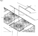
- the cooling fields can have different structures. It is important that the channels for the heated coolant or the coolant that has been converted into vapor are curved, i.e. have at least one curve. This ensures that the weight has little influence on the flow and that liquid droplets are not thrown out.
- the coolant runs in a ring and/or wave shape (layer (2)) and is then discharged again via the distributor structure (layer (3)).
- the coolant used according to the invention is preferably liquid. In the simplest case, this is water. Other coolants can also be used. Examples are ammonia, butane, glycol, fluorochlorinated hydrocarbons and propane. All other coolants known to those skilled in the art can also be used. Two or more of the coolants mentioned can also be used in combinations.
- a distribution structure for the supply of coolant.
- the coolant is supplied separately to the individual fields via this structure.
- the even distribution of the coolant to the respective fields is achieved by the pressure loss over each cooling field being significantly greater than the pressure loss in the channels of the distribution structure.
- the individual cooling fields are provided with lines for the inlet and outlet of the coolant.
- each individual cooling field there is an inlet and an outlet for the coolant.
- the supply lines for the coolant are designed with a descending hydraulic diameter in the direction of flow of the coolant.
- the discharge channels are designed with an ascending hydraulic diameter in the direction of flow of the coolant.
- the discharge channels are preferably 2 to 20 times larger than the supply channels. In the case of pressureless use, a diameter up to 100 times larger can also be considered.
- the hydraulic diameter of the supply channels is preferably 500 ⁇ m to 5 mm, particularly preferably 700 ⁇ m to 2 mm. In principle, the hydraulic diameter depends on the total length and the number of coolant distributions. The hydraulic diameter increases with the number of distributions.
- the supply and removal of the coolant are therefore within one layer, in other words on an identical level.
- the heat flows between the reaction layer (layer 1) and the cooling fields in a separate layer (2) are decoupled from the inlet temperature of the coolant.
- cooling is achieved by means of the cooling fields.
- the separate supply of the coolant to the individual cooling fields along the reaction section results in even cooling distributed over the length of the reaction.
- the heated coolant is again individually discharged from each cooling field.
- the coolant can preferably evaporate and is discharged again via the discharge lines. This means that according to the invention, an even distribution of fresh coolant and a discharge of steam heated by the exothermic reaction are achieved over the entire reaction section.
- the lines for discharging the steam from the cooling fields are arranged at a maximum distance from the coolant-carrying distribution structures, i.e. between the coolant supply and discharge lines, i.e. between the supply lines that conduct the cooler coolant to the cooling fields and the discharge lines that discharge the heated coolant, possibly steam, from the stack sequence/reactor. This prevents heat conduction between these sections.
- the distribution structure has a parallel arrangement (parallel arrangement) of several, preferably symmetrical arrangement of the lines for supplying and removing the coolant.
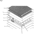
- the figures show the individual layers, including the unstructured layer 8, i.e. layer a designated by number 1, layer b) designated by number 2, and layer c) designated by number 3.
- Layer 2 is arranged beneath layer 1, and beneath that the distributor structure 3.
- layer 2 with the cooling fields 6 is located between layer 1 and the distributor structure 3.
- Above and below this stacking sequence there are further stacking sequences which are a mirror image of the stacking sequence described.
- the coolant is led via line 7 via line 10 into the cooling fields 6.
- the heated coolant which is usually in the form of steam, e.g. water 4, is discharged via line 5.
- the steam that is regularly produced is finally removed via line 9.
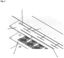
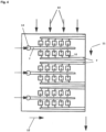
- the supply of the coolant e.g. water 4 can be carried out separately via the input 14 into the supply line 7. From there, the coolant is supplied to the various cooling fields 6 via the line 10.
- the Coolant in line 7 in the transverse direction 12 to the direction of the volume flow of the reactant 13. This means that the reactant 13 is guided in the longitudinal direction 11 to the coolant, e.g. water 4.
Landscapes
- Chemical & Material Sciences (AREA)
- Organic Chemistry (AREA)
- Chemical Kinetics & Catalysis (AREA)
- Physical Or Chemical Processes And Apparatus (AREA)
Description
- Die vorliegende Erfindung betrifft einen Mikrostrukturreaktor für die Durchführung von exothermen katalytischen Reaktionen.
- Mikrostrukturreaktoren sind bereits in verschiedenen Ausführungen realisiert worden und werden bereits in einer Mikroverfahrenstechnik für bestimmte Anwendungen kommerziell eingesetzt. Die Auslegung erfolgt unter der speziellen Berücksichtigung mikrotechnischer Randbedingungen. Ein Mikrostrukturreaktor umfasst mindestens, aber nicht ausschließlich, eine Reaktionszone mit mindestens einem Einlauf und mindestens einem Ablauf. In den Reaktionszonen erfolgen kontrollierte Reaktionen, wobei in mindestens einer Reaktionsszone ein Katalysator zum Einsatz kommt. Eine Ausführung ist auch ohne Katalysator möglich. Grundsätzlich sind die Reaktionszonen als Misch-, oder als Durchflusskavitäten mit Fluidzusammenführung und/oder Aufzweigungen gestaltbar.
- Üblicherweise wird zwischen einfachem Kreuzstrom- und Gegen- bzw. Gleichstromverfahren unterschieden. In vielen Fällen besteht ein kreuzstromartiger Anteil. Bei der Verwendung von Kühlmitteln, die keinen Phasenwechsel durchlaufen, ergibt sich eine ungleichmäßige Kapazität zur Kühlung der unterschiedlichen Reaktionskanäle innerhalb einer Platte des Gesamtsystems. Die Anzahl der überstrichenen Reaktionskanäle ist für jeden Kühlkanal unterschiedlich. Der Anstieg der Temperatur führt dazu, dass eine höhere Temperatur im darunter liegenden Kühlkanal auftritt. Diese führt aufgrund der exponentiellen Zunahme der Reaktionsgeschwindigkeit der chemischen Reaktion mit der Temperatur im jeweiligen Reaktionskanal zu einer zusätzlichen Diskrepanz zwischen der Kühlfähigkeit des Kühlmittels und dem Vermögen der Reaktion zur Wärmeentwicklung. Außerdem ändert sich die Viskosität der Fluide, was wiederum zu einer Ungleichverteilung der Medien auf die einzelnen Kanäle und auf der Kühlplatte als auch der Reaktionsplatte führt, die ebenso unerwünscht ist. In diesem Zusammenhang ist die Ungleichverteilung des Reaktionsmediums eine Herausforderung, weil dies automatisch eine unterschiedliche Verweilzeit bedeutet.
- Im Falle einer Verdampfungskühlung ist der Sachverhalt noch komplizierter. Ebenso wie bei der Verwendung einphasig bleibender Kühlmittel ändert sich die abzuführende Wärme entlang des Reaktionskanals. Bei einer mindestens partiell vorliegenden Kreuzstromanordnung bedeutet dies einen unterschiedlichen Verdampfungsgrad. Dies ist im Sinne der Nutzung des erzeugten Dampfs für andere Teilsysteme in einem Gesamtprozess für die Wirkungsgraderhöhung der gesamten Prozesskette unerwünscht. Diese gleichmäßige Verteilung wird zusätzlich bezüglich des erzielbaren Gesamtdampfgrades des Kühlmittels negativ beeinflusst. So wird über Bereichen, in denen die Reaktion schneller verläuft, zunächst Dampf entwickelt. Die dort auftretende Zunahme der Geschwindigkeit des Kühlmittels führt zu einer Abnahme des Durchsatzes des spezifischen Kühlkanals durch die Kommunikation bezüglich des Druckes im Gesamtsystem und verstärkt damit den Effekt des unterschiedlichen Verdampfungsgrades des Kühlmittels zwischen den Kanälen einer Platte. Zudem wird die Temperaturkontrolle der Reaktion erschwert. Die mit reinem Dampf überstrichenen Reaktionskanäle können nicht mehr ausreichend gekühlt werden, da der Massenstrom und die spezifische Wärmekapazität des Dampfes deutlich geringer sind.
- Ferner ist der allgemein übliche Flächen- und Volumenbedarf der katalytischen Reaktion (> 90 % aller Fälle) deutlich größer als die Kanaloberfläche, die benötigt wird, um die Reaktionswärme abzutransportieren. D.h. die Ebene mit Kühlkanälen ist üblicherweise stark überdimensioniert. Mit anderen Worten, der mögliche Wärmeübergangskoeffizient ist je nach Sichtweise höher als benötigt. Außerdem ist der kalkulierbare Wärmestrom pro Plattenpaar bestehend aus Reaktion und Kühlung größer als die zu übertragende Reaktionsenthalpie. Diese Tatsache kann zusätzlich den Effekt der lokal ungleichmäßigen Verdampfung transversal zu der Reihe der Reaktionskanäle verstärken. Denn die Verdampfung des Kühlmittels kann früher eintreten und vorzeitig abgeschlossen sein. Im Extremfall kann der Verdampfungsvorgang bereits vor den eigentlichen Kühlkanälen erfolgen und die Verteilung des Kühlmittels in longitudinaler Richtung der Reaktionskanäle erschwert werden. Da die Reaktionskanäle häufig vertikal ausgerichtet werden, heißt dies implizit, dass die Verteilung zu den Kühlkanälen ebenfalls vertikal erfolgt und durch die Gravitation beeinflusst wird. So kann schließlich durch Blasenbildung vor den Kühlkanälen der Zugang zu bestimmten Bereichen verhindert sein.
- Zur Lösung der aufgezeigten Probleme gibt es im Stand der Technik einige Lösungsansätze. So wird in der
WO 002004017008 WO 002004037418 WO 002005044442 WO 002005075606 WO 002005082519 WO 002005065387 WO 002011075746 WO 002012054455 WO 2011134630 ist die Verteilung von Reaktionsgas im Kühlmittel mit partieller Kreuzstromanordnung, partieller Zudosierung von Reaktanden und Wärmetausch ganz allgemein dargestellt. Schließlich beschreibt dieUS 6994829 die Nutzung (gewundener) kleiner Kanäle zur Verdampfung gepaart mit der anschließenden Überhitzung in geraden, größeren Kanälen. Die Kopplung zweier Reaktionen ist aus derUS 7014835 sowie derDE 10044526 bekannt. Die Nutzung der Säulenstruktur für mehrphasige Reaktionen mit Zufuhr von Reaktanten ergibt sich aus derDE 102005022958 . Eine Darstellung der sequentiellen Durchführung katalytischer Reaktionen mit Zwischenkühlung ist in derDE 10201210344 vorhanden. - In keinem dieser Dokumente wird die notwendige Maßnahme zur effektiven Verteilung von Kühlmittel in kreuzstromartigen Anordnungen beschrieben, welches vollständig verdampft, aber nicht zwangsläufig überhitzt werden soll. Die partielle Zudosierung wird für Reaktionen verwendet und graduierte Katalysatorbetten/Kühlzonen zur besseren Kühlung vorgeschlagen.
-
EP 1123734 A2 offenbart einen Mikrostrukturreaktor zur Durchführung einer Reaktion zwischen zwei Reaktanten umfassend eine Vielzahl schichtweise angeordneter Platten für die Leitung und Verteilung der Reaktanten sowie von Wärmeträgermedien. - Aufgabe der vorliegenden Erfindung ist es demgemäß, den beschriebenen Problemen abzuhelfen. Insbesondere bleibt die Herausforderung durch parallelisierte Verteilungsstrukturen eine gleichmäßige Temperatur im Gesamtreaktor zu erzielen bestehen.
- Gelöst wird diese Aufgabe durch einen Mikrostrukturreaktor zur Durchführung einer exothermen Reaktion zwischen zwei oder mehr Reaktanten, welche in Form von Fluiden über einen oder mehrere Katalysator(en) geleitet werden, gemäß den angehängten Ansprüchen 1 bis 14.
- Erfindungsgemäß handelt es sich mithin um mindestens eine Stapelfolge. Demgemäß kann der Mikrostrukturreaktor beliebige Anzahlen von Stapelfolgen aufweisen. Dabei können die einzelnen Lagen plattenförmig oder folienförmig ausgestaltet werden.
- Die Dicken der einzelnen Lagen können vorzugsweise in folgenden Bereichen liegen:
- Lage a) 0,5 mm bis 10 mm, vorzugsweise 1 mm bis 3 mm
- Lage b) 0,1 mm bis 5 mm, vorzugsweise 0,3 mm bis 0,6 mm
- Lage c) 1 mm bis 10 mm, vorzugsweise 1 mm bis 3 mm
- Erfindungsgemäß können eine oder mehrere Lagen an ihren Oberflächen Strukturen aufweisen. Die in der Lage a) angeordneten Strukturen dienen der Aufnahme der Katalysatoren. Bei diesen Strukturen kann es sich mithin um Reaktionskanäle oder auch sogenannte Reaktionsschlitze handeln, welche mit Partikeln des Katalysatormaterials befüllt oder mit Katalysator beschichtet werden. Die Höhe der Reaktionskanäle kann zwischen 0,4 mm und 8 mm, vorzugsweise 0,8 mm und 1,5 mm liegen.
- Als Katalysatoren kommen erfindungsgemäß vorzugsweise Kobalt, Eisen, Nickel, Rhodium oder Rhutenium in Betracht. Es können auch Verbindungen eingesetzt werden, welche diese Elemente enthalten. Ebenso sind Kombinationen eines oder mehrerer der genannten Elemente möglich. Ebenso können die genannten Katalysatoren mit weiteren nicht genannten geeigneten, dem Fachmann bekannten Katalysatoren verwendet werden.
- Erfindungsgemäß dienen die Katalysatoren der Durchführung von Reaktionen. Es handelt sich hierbei erfindungsgemäß um exotherme Reaktionen. Vorzugsweise werden hierfür Fluide, welche die Reaktanten enthalten oder daraus bestehen, über die katalysatorhaltigen Oberflächen geleitet. Es kann sich hierbei um gasförmige oder flüssige Fluide handeln, welche die betreffenden Reaktanten enthalten oder daraus bestehen. Damit bildet sich über den Katalysatoren ein Reaktionsbereich aus, in dem es zur Umsetzung der Fluide kommt. Bei den erfindungsgemäß eingesetzten Fluiden können beispielsweise Synthesegase, Wasserstoff/Sauerstoff und Kohlenwasserstoffe, wie Methane, Alkene u.s.w. zum Einsatz kommen. Zwei oder mehr der genannten Fluide können beliebig kombiniert werden.
- Ein Anwendungsbeispiel ist die Fischer-Tropsch-Reaktion. Bei dieser wird aus Synthesegas bei einer Mischung aus Kohlenmonoxid und Wasserstoffgas eine Vielzahl von überwiegend aus Alkanen unterschiedlicher Kettenlänge bestehenden Flüssigkeiten gebildet, die durch entsprechende Aufbereitungsschritte in Diesel oder kerosinhaltige synthetische Kraftstoffe umgewandelt werden. Bei der Umwandlung können gegebenenfalls auch Olefine und Isomere entstehen. Die Alkane können in flüssiger oder auch gasförmiger Form vorliegen. Die betreffende Reaktion ist stark exotherm und in dem vorliegenden Mikrostrukturreaktor durchführbar.
- Die erfindungsgemäße Stapelfolge enthält als Lage b) Kühlfelder. D. h. in dieser Lage sind zwei oder mehrere Kühlfelder angeordnet. Die in der Reaktionsfläche anfallende Wärme wird von diesen Kühlfeldern aufgenommen. Die einzelnen Felder haben gleiche Kühleigenschaften oder weisen im Verhältnis zueinander die gleiche Kühlleistung auf. Damit wird eine gleichmäßige Kühlung des gesamten Reaktionsbereiches erreicht. Jedes Feld entlang eines spezifischen Versorgungskanals und/oder der Verteilerstruktur wird erfindungsgemäß mit der nahezu gleichen Menge an Kühlmittel bei nahezu gleicher Temperatur, versorgt.
- Die Kühlfelder können verschiedene Strukturen haben. Wesentlich ist, dass die Kanäle für das erwärmte bzw. in die Dampfform überführte Kühlmittel gekrümmt sind, also mindestens eine Krümmung aufweisen. Hierdurch wird erreicht, dass die Gewichtskraft wenig Einfluss auf die Strömung hat und ein Ausschleudern von Flüssigkeitstropfen vermieden wird. In den Kühlfeldern verläuft das Kühlmittel ring- und/oder wellenförmig (Lage (2)) und wird dann über die Verteilerstruktur (Lage (3)) wieder abgeführt.
- Das erfindungsgemäß eingesetzte Kühlmittel ist vorzugsweise flüssig. Im einfachsten Falle handelt es sich um Wasser. Daneben sind auch andere Kühlmittel einsetzbar. Beispiele sind Ammoniak, Butan, Glykol, Fluor chlorierte Kohlenwasserstoffe und Propan. Auch alle anderen dem Fachmann bekannten Kühlmittel können zum Einsatz kommen. Zwei oder mehrere der genannten Kühlmittel können auch in Verbindungskombiantionen eingesetzt werden.
- Erfindungsgemäß ist eine Verteilerstruktur für die Zufuhr von Kühlmittel vorgesehen. Über diese Struktur erfolgt die getrennte Zuleitung des Kühlmittels zu den einzelnen Feldern. Die Gleichverteilung des Kühlmittels auf die jeweiligen Felder wird dadurch erreicht, dass der Druckverlust über jedem Kühlfeld wesentlich größer als der Druckverlust in den Kanälen der Verteiler Struktur ist.
- Erfindungsgemäß sind die einzelnen Kühlfelder mit Leitungen für den Ein- und Ablauf des Kühlmittels vorgesehen. In jedem einzelnen Kühlfeld gibt es einen Zulauf und einen Ablauf für das Kühlmittel.
- Erfindungsgemäß sind die Zufuhrleitungen für das Kühlmittel im hydraulischen Durchmesser in Fließrichtung des Kühlmittels absteigend ausgelegt. Die Abfuhrkanäle sind im Gegensatz dazu im hydraulischen Durchmesser in Fließrichtung des Kühlmittels aufsteigend angelegt. Vorzugsweise sind die Abfuhrkanäle 2 bis 20-fach größer als die Zufuhrkanäle. Bei druckloser Anwendung kann auch ein bis zu 100-fach größerer Durchmesser in Betracht kommen. Der hydraulische Durchmesser der Zufuhrkanäle liegt bevorzugt bei 500 µm bis 5 mm, besonders bevorzugt bei 700 µm bis 2 mm. Grundsätzlich ist der hydraulische Durchmesser von der Gesamtlänge und der Anzahl der Verteilung des Kühlmittels abhängig. Mit der Zahl der Verteilungen wächst der hydraulische Durchmesser.
- Zufuhr und Abfuhr des Kühlmittels liegen mithin innerhalb einer Lage, mit anderen Worten auf einer identischer Ebene. Die Kühlung, gegebenenfalls die Verdampfung des Kühlmittels findet in einer anderen Lage (Ebene statt). Dadurch sind die Wärmeströme zwischen Reaktionslage (Lage 1) und Kühlfeldern in einer getrennten Lage (2) von der Eintrittstemperatur des Kühlmittels entkoppelt.
- Bei der Durchführung der erfindungsgemäßen exothermen Reaktionen wird mittels der Kühlfelder die Kühlung erreicht. Durch die getrennte Zufuhr des Kühlmittels zu den einzelnen Kühlfeldern entlang der Reaktionsstrecke kommt es insgesamt verteilt über die Länge der Reaktion zu einer gleichmäßigen Kühlung. Das erwärmte Kühlmittel wird wieder einzeln von jedem Kühlfeld abgeführt. Im Rahmen der Erfindung kann es vorzugsweise zu einer Verdampfung des Kühlmittels kommen, welches über die Abfuhrleitungen wieder abgeführt wird. D.h. erfindungsgemäß wird eine gleichmäßige Verteilung von frischem Kühlmittel und eine Abfuhr von durch die exotherme Reaktion erwärmten Dampf über die gesamte Reaktionsstrecke erreicht. Hierbei sind die Leitungen zur Abfuhr des Dampfes aus den Kühlfeldern mit maximalem Abstand von den kühlmittelführenden Verteilerstrukturen angeordnet, d.h. zwischen Zu- und Ableitungen des Kühlmittels, also zwischen den Zufuhrleitungen die das kühlere Kühlmittel zu den Kühlfeldern leiten und den Abfuhrleitungen, die das erwärmte Kühlmittel, gegebenenfalls Dampf aus dem der Stapelfolge / Reaktor ableiten. Damit wird eine Wärmeleitung zwischen diesen Abschnitten verhindert.
- Durch die Entkoppelung der Wärmeströme zwischen Reaktionslage (Lage 1) und Kühlfeldern in Lage 2 von der Eintrittstemperatur des Kühlmittels wird die Vergleichmäßigung der Temperatur in der Reaktionszone trotz eines deutlich unterhalb der Siedetemperatur eintretenden Kühlmittels auf einer, gegebenenfalls bis zu mehreren Quadratmetern großen Fläche der verschiedenen Lagen gewährleistet. Die Verwendung einer Kombination von zwei Lagen, eine für die Kühlung mittels Kühlfelder die andere für die Verteilerstruktur des Kühlmittels verhindert die Überhitzung des Reaktors und stellt eine gleichmäßige Temperaturverteilung, im Wesentlichen eine Isothermie sicher. Verteilerstruktur weist eine parallelisierte Anordung (parallele Anordnung) von mehreren, bevorzugt symmetrischeAnordnung der Leitungen zur Zu- und Abfuhr des Kühlmittels auf. Dies bewirkt eine Stromführung in einem periodischen Wechsel zwischen Gegenstrom und Gleichstrom zwischen den Zu- und Ableitungen - aber in Kreuzstrom zur Stromführung der Reaktanden - ohne die Berücksichtigung der Stromführung in Lage der Kühlfelder. Auch dadurch wird ein maximaler Abstand zwischen Zu- und Ableitungen des Kühlmittels wie oben beschrieben erzielt.
-
- 1.
- Lage a)
- 2.
- Lage b)
- 3.
- Lage c)
- 4.
- Wasser
- 5.
- Dampf
- 6.
- Kühlfeld
- 7.
- Zufuhr von Kühlmitteln
- 8.
- Unstrukturierte Lage
- 9.
- Abfuhr von Dampf
- 10.
- Zuleitung zu verschiedenen Kühlfeldern
- 11.
- Longitudinale Führung des Reaktionsmediums
- 12.
- Transversale Richtung des Kühlmittels
- 13.
- Reaktionsmedium
- 14.
- Getrennte Eingabe von Kühlmittel
-
-
Figur 1 zeigt im Detail die Anordnung der Lagen. -
Figur 2 zeigt die Kühlfelder mit den Zu- und Abfuhrleitungen. -
Figur 3 zeigt in räumlicher Darstellung die Zufuhr und Abfuhr des Kühlmittels. -
Figur 4 Führung des Reaktionsmediums und des Kühlmittels. - Aus den Figuren sind die einzelnen Lagen einschließlich der unstrukturierten Lage 8 ersichtlich, d. h. die mit der Ziffer 1 bezeichnete Lage a), die mit der Ziffer 2 gekennzeichneten Lage b) und die mit der Ziffer 3 gekennzeichnete Lage c). Unter der Lage 1 sind die Lage 2 und darunter die Verteilerstruktur 3 angeordnet. Mit anderen Worten, zwischen Lage 1 und der Verteilerstruktur 3 befindet sich die Lage 2 mit den Kühlfeldern 6. Über und unter dieser Stapelfolge schließen sich weitere Stapelfolgen an, die spiegelbildlich zu der beschriebenen Stapelfolge angelegt sind. Über die Leitung 7 wird hierbei das Kühlmittel über die Leitung 10 in die Kühlfelder 6 geführt. Dort erwärmt sich das Kühlmittel infolge der exothermen Reaktion, welche unter Einfluss der Katalysatoren in der Lage 1 entsteht. Das erwärmte in der Regel als Dampf vorliegende Kühlmittel, z. B. Wasser 4, wird über die Leitung 5 abgeführt. Die Abfuhr des regelmäßig entstehenden Dampfes erfolgt schließlich über die Leitung 9. Dadurch wird das Entstehen eines Temperaturgradienten vermieden, welcher regelmäßig dann die Folge bei der exothermen Reaktion ist, bei denen das Kühlmittel entlang der Reaktionsstrecke geführt wird. Bei diesen Konstruktionen nach dem Stand der Technik erwärmt sich allmählich das Kühlmittel und kann sich im Extremfall an die Reaktionstemperatur angleichen.
- Die Zuleitung des Kühlmittels, z. B. Wasser 4, kann über die Eingabe 14 in die Zufuhrleitung 7 getrennt erfolgen. Von dort erfolgt über die Leitung 10 die Zuleitung des Kühlmittels zu den verschiedenen Kühlfeldern 6. Hierbei erfolgt die Führung des Kühlmittels in Leitung 7 in transversaler Richtung 12 zur Richtung des Volumenstroms des Reaktionsmittels 13. D. h., das Reaktionsmittel 13 wird in longitudinaler Richtung 11 zum Kühlmittel, z. B. Wasser 4, geführt.
Claims (14)
- Mikrostrukturreaktor zur Durchführung einer exothermen Reaktion zwischen zwei oder mehr Reaktanten, welche in Form von Fluiden über einen oder mehrere Katalysator(en) geleitet werden, umfassend wenigstens eine Stapelfolge vona) wenigstens einer einen oder mehrere Katalysator(en) aufweisenden Lage (1) zur Durchführung wenigstens einer exothermen Reaktion,b) wenigstens einer in zwei oder mehrere Kühlfelder (6) unterteilten Lage (2), wobei die Kanäle für das erwärmte bzw. in die Dampfform überführte Kühlmittel gekrümmt sind und wobei es in jedem einzelnen Kühlfeld einen Zulauf und einen Ablauf für das Kühlmittel gibt,c) wenigstens einer Verteilerstrukturen aufweisenden Lage (3) für die getrennte Zuleitung des Kühlmittels zu den einzelnen Feldern,- mit Leitungen zur Verteilung des Kühlmittels,- mit Anschlüssen für die Zufuhr von Kühlmittel zu den Leitungen der Verteilerstruktur und für die Verbindung zu den Kühlfeldern,- Anschlüssen zur Abfuhr des erwärmten Kühlmittels aus den Kühlfeldern und- Leitungen und Anschlüssen zur Abfuhr des erwärmten Kühlmittels aus der Stapelfolge.
- Mikrostrukturreaktor nach Anspruch 1 dadurch gekennzeichnet, dass er mehrere Stapelfolgen aufweist.
- Mikrostrukturreaktor nach einem der vorhergehenden Ansprüche dadurch gekennzeichnet, dass die einzelnen Lagen plattenförmig oder folienförmig ausgestaltet sind.
- Mikrostrukturreaktor nach Anspruch 3 dadurch gekennzeichnet, dass die einzelnen Lagen folgende Dicken aufweisen:Lage a) 0, 5 mm bis 10 mm,Lage b) 0,1 mm bis 5 mm,Lage c) 1 mm bis 10 mm.
- Mikrostrukturreaktor nach einem der vorhergehenden Ansprüche dadurch gekennzeichnet, dass eine oder mehrere Lagen an ihren Oberfläche Strukturen aufweisen.
- Mikrostrukturreaktor nach Anspruch 5 dadurch gekennzeichnet, dass die Katalysatoren in die Strukturen gefüllt sind.
- Mikrostrukturreaktor nach Anspruch 6 dadurch gekennzeichnet, dass die Strukturen Reaktionskanäle oder Reaktionsschlitze sind, welche mit Partikeln befüllt sind.
- Mikrostrukturreaktor nach Anspruch 7 dadurch gekennzeichnet, dass die Reaktionskanäle oder Reaktionsschlitze eine Höhe von 0,4 mm bis 8 mm aufweisen.
- Mikrostrukturreaktor nach einem der vorhergehenden Ansprüche dadurch gekennzeichnet, dass innerhalb der Verteilungsstrukturen die Leitungen der kühlmittelführenden Zufuhr mit maximalem Abstand von den Leitungen zur Abfuhr des Kühlmittels aus den Kühlfeldern angeordnet sind.
- Mikrostrukturreaktor nach Anspruch 9 dadurch gekennzeichnet, dass die Zufuhrleitungen für das Kühlmittel im hydraulischen Durchmesser in Fließrichtung des Kühlmittels absteigend sind.
- Mikrostrukturreaktor nach Anspruch 10 dadurch gekennzeichnet, dass die Abführleitungen für den Dampf im hydraulischen Durchmesser in Fließrichtung des Kühlmittels ansteigend sind.
- Mikrostrukturreaktor nach einem der vorhergehenden Ansprüche dadurch gekennzeichnet, dass jedes Kühlfeld eine einzelne Zu- und Abfuhr des Kühlmittels in der Verteilerstruktur aufweist.
- Mikrostrukturreaktor nach einem der vorhergehenden Ansprüche dadurch gekennzeichnet, dass die Katalysatoren Kobalt, Eisen, Nickel, Rhodium oder Ruthenium-Katalysator sind oder solche Elemente enthalten.
- Mikrostrukturreaktor nach einem der vorhergehenden Ansprüche dadurch gekennzeichnet, dass die Zu- und Abfuhr des Kühlmittels in der Verteilerstruktur im Kreuzstrom zur Stromführung der Reaktanden angeordnet sind.
Applications Claiming Priority (2)
| Application Number | Priority Date | Filing Date | Title |
|---|---|---|---|
| DE102015111614.6A DE102015111614A1 (de) | 2015-07-17 | 2015-07-17 | Mikrostrukturreaktor zur Durchführung exothermer, heterogen katalysierter Reaktionen mit effizienter Verdampfungskühlung |
| PCT/EP2016/066869 WO2017013003A1 (de) | 2015-07-17 | 2016-07-15 | Mikrostrukturreaktor zur durchführung exothermer, heterogen katalysierter reaktionen mit effizienter verdampfungskühlung |
Publications (3)
| Publication Number | Publication Date |
|---|---|
| EP3325142A1 EP3325142A1 (de) | 2018-05-30 |
| EP3325142B1 true EP3325142B1 (de) | 2024-08-28 |
| EP3325142C0 EP3325142C0 (de) | 2024-08-28 |
Family
ID=56557668
Family Applications (1)
| Application Number | Title | Priority Date | Filing Date |
|---|---|---|---|
| EP16745425.5A Active EP3325142B1 (de) | 2015-07-17 | 2016-07-15 | Mikrostrukturreaktor zur durchführung exothermer, heterogen katalysierter reaktionen mit effizienter verdampfungskühlung |
Country Status (6)
| Country | Link |
|---|---|
| US (1) | US10150093B2 (de) |
| EP (1) | EP3325142B1 (de) |
| CN (2) | CN107847899A (de) |
| DE (1) | DE102015111614A1 (de) |
| ES (1) | ES2993736T3 (de) |
| WO (1) | WO2017013003A1 (de) |
Families Citing this family (9)
| Publication number | Priority date | Publication date | Assignee | Title |
|---|---|---|---|---|
| FR3110961B1 (fr) * | 2020-05-27 | 2022-07-01 | Air Liquide | Procédé et dispositif de refroidissement cryogénique |
| DE102020128868A1 (de) | 2020-11-03 | 2022-05-05 | Karlsruher Institut für Technologie | Umwandlung von CO2 in chemische Energieträger und Produkte |
| DE102021110735A1 (de) | 2021-04-27 | 2022-10-27 | Ineratec Gmbh | Verfahren zur Herstellung von Kohlenwasserstoffen |
| DE102021115881A1 (de) | 2021-06-18 | 2022-12-22 | Ineratec Gmbh | Multilagenreaktor mit mehreren Strukturlagen |
| CA3227482A1 (en) | 2021-08-02 | 2023-02-09 | Velocys Technologies Limited | Process for operating a plant facility during catalyst regeneration |
| GB2609508B (en) | 2021-08-02 | 2023-10-18 | Velocys Tech Ltd | Process |
| CN116786072B (zh) * | 2023-05-23 | 2025-08-19 | 武汉船用电力推进装置研究所(中国船舶集团有限公司第七一二研究所) | 一种液体有机储氢材料脱氢反应器和脱氢装置 |
| DE102023121365A1 (de) * | 2023-08-10 | 2025-02-13 | Ineratec Gmbh | Regulierung der Kühlmittelzufuhr bei Mikroreaktoren |
| DE102024118229A1 (de) * | 2024-06-27 | 2025-12-31 | Ineratec Gmbh | Vorrichtung und Verfahren zur verbesserten Kühlmittelzirkulierung bei (mikro-)strukturierten Reaktoren |
Family Cites Families (24)
| Publication number | Priority date | Publication date | Assignee | Title |
|---|---|---|---|---|
| US5811062A (en) * | 1994-07-29 | 1998-09-22 | Battelle Memorial Institute | Microcomponent chemical process sheet architecture |
| DE19912318A1 (de) | 1999-03-19 | 2000-09-28 | Dbb Fuel Cell Engines Gmbh | Plattenreaktor |
| US6537506B1 (en) | 2000-02-03 | 2003-03-25 | Cellular Process Chemistry, Inc. | Miniaturized reaction apparatus |
| DE10044526A1 (de) | 2000-09-04 | 2002-04-04 | Mannesmann Ag | Mikrostrukturreaktor und Verfahren zur Durchführung chemischer Reaktionen |
| US6994829B2 (en) | 2001-06-06 | 2006-02-07 | Battelle Memorial Institute | Fluid processing device and method |
| US7014835B2 (en) | 2002-08-15 | 2006-03-21 | Velocys, Inc. | Multi-stream microchannel device |
| US6622519B1 (en) | 2002-08-15 | 2003-09-23 | Velocys, Inc. | Process for cooling a product in a heat exchanger employing microchannels for the flow of refrigerant and product |
| US7404936B2 (en) | 2002-10-22 | 2008-07-29 | Velocys | Catalysts, in microchannel apparatus, and reactions using same |
| DE10317451A1 (de) * | 2003-04-16 | 2004-11-18 | Degussa Ag | Reaktor für heterogen katalysierte Reaktionen |
| US7422910B2 (en) | 2003-10-27 | 2008-09-09 | Velocys | Manifold designs, and flow control in multichannel microchannel devices |
| US20050141843A1 (en) | 2003-12-31 | 2005-06-30 | Invitrogen Corporation | Waveguide comprising scattered light detectable particles |
| US7084180B2 (en) | 2004-01-28 | 2006-08-01 | Velocys, Inc. | Fischer-tropsch synthesis using microchannel technology and novel catalyst and microchannel reactor |
| US8747805B2 (en) | 2004-02-11 | 2014-06-10 | Velocys, Inc. | Process for conducting an equilibrium limited chemical reaction using microchannel technology |
| DE102005022958B3 (de) | 2005-05-19 | 2006-07-20 | Forschungszentrum Karlsruhe Gmbh | Mikrostrukturreaktor und Verwendung desselben |
| CA2634417A1 (en) * | 2005-12-22 | 2007-06-28 | Dominicus Maria Rekers | Microchannel apparatus for unit operations following ethylene oxide production |
| CN100455345C (zh) * | 2006-07-17 | 2009-01-28 | 南京工业大学 | 复合换热式微反应器 |
| US8802039B2 (en) | 2009-12-18 | 2014-08-12 | Velocys, Inc. | Microchannel technology having structures with reduced material and enhanced volumetric productivity |
| DE102010018869A1 (de) | 2010-04-30 | 2011-11-03 | Karlsruher Institut für Technologie | Wärmetauscher zum schnellen Erhitzen und Abkühlen von Fluiden |
| US20120095268A1 (en) | 2010-10-18 | 2012-04-19 | Anna Lee Tonkovich | Microchannel processor |
| US20120097391A1 (en) | 2010-10-22 | 2012-04-26 | Enventure Global Technology, L.L.C. | Expandable casing patch |
| DE102011010021A1 (de) * | 2011-02-02 | 2012-08-02 | Karlsruher Institut für Technologie | Kreuzstrom-Wärmeübertrager |
| JP5485472B2 (ja) * | 2011-04-15 | 2014-05-07 | コリア インスティテュート オブ エナジー リサーチ | 微細流路加熱器を用いた炭化水素改質装置 |
| DE102012100344A1 (de) | 2012-01-17 | 2013-07-18 | Karlsruher Institut für Technologie | Mikroreaktor für katalytische Reaktionen |
| CN204107488U (zh) * | 2014-08-27 | 2015-01-21 | 上海理工大学 | 集成微反应装置 |
-
2015
- 2015-07-17 DE DE102015111614.6A patent/DE102015111614A1/de not_active Ceased
-
2016
- 2016-07-15 EP EP16745425.5A patent/EP3325142B1/de active Active
- 2016-07-15 WO PCT/EP2016/066869 patent/WO2017013003A1/de not_active Ceased
- 2016-07-15 CN CN201680041647.6A patent/CN107847899A/zh active Pending
- 2016-07-15 ES ES16745425T patent/ES2993736T3/es active Active
- 2016-07-15 CN CN202411393594.7A patent/CN119258938A/zh active Pending
- 2016-07-15 US US15/743,765 patent/US10150093B2/en active Active
Also Published As
| Publication number | Publication date |
|---|---|
| EP3325142A1 (de) | 2018-05-30 |
| CN119258938A (zh) | 2025-01-07 |
| DE102015111614A1 (de) | 2017-01-19 |
| ES2993736T3 (en) | 2025-01-08 |
| EP3325142C0 (de) | 2024-08-28 |
| CN107847899A (zh) | 2018-03-27 |
| US10150093B2 (en) | 2018-12-11 |
| CA2991942A1 (en) | 2017-01-26 |
| WO2017013003A1 (de) | 2017-01-26 |
| US20180207607A1 (en) | 2018-07-26 |
Similar Documents
| Publication | Publication Date | Title |
|---|---|---|
| EP3325142B1 (de) | Mikrostrukturreaktor zur durchführung exothermer, heterogen katalysierter reaktionen mit effizienter verdampfungskühlung | |
| DE69413691T2 (de) | Verfahren und vorrichtung zur regulierung der temperaturen von reaktionen | |
| EP1485195B1 (de) | Verfahren zur herstellung von phosgen | |
| EP1613424B1 (de) | Mikroreaktor in plattenbauweise mit einem katalysator | |
| EP2379217B1 (de) | Reaktor und verfahren zur herstellung von phosgen | |
| EP2379216B1 (de) | Reaktor und verfahren zur herstellung von phosgen | |
| DE112015004756T5 (de) | Verfahren der Entfernung von Wärme | |
| EP2032676A2 (de) | Paraffin-alkylierung | |
| EP1586370A2 (de) | Reaktoranordnung zur Durchführung katalytischer Gasphasenreaktionen | |
| EP4355474B1 (de) | Multilagenreaktor mit mehreren strukturlagen | |
| WO2022089521A1 (zh) | 一种重油加氢反应系统及重油加氢方法 | |
| EP2872443B1 (de) | Vorrichtung und verfahren zur herstellung von phosgen | |
| EP1234612A2 (de) | Reaktor zur Durchführung von katalysierten Reaktionen | |
| CA1274852A (en) | Catalytic conversion of liquid and/or gas | |
| EP1286763A2 (de) | Gegenstrom-reaktor mit einem kontaktrohrbündel | |
| DE60106212T2 (de) | Chemischer reaktor mit wärmetauscher | |
| JP7616832B2 (ja) | 区画化型オリゴマー化反応器 | |
| CA2991942C (en) | Microstructure reactor for carrying out exothermic heterogenously-catalysed reactions with efficient evaporative cooling | |
| DE60110625T2 (de) | Reaktor zur chemischen umwandlung eines ausgangsmaterials mit wärmezufuhr und ausgangsmaterial/katalysator-querzirkulation | |
| DE102008025887A1 (de) | Verfahren zur Herstellung von Formaldehyd | |
| DE60222630T3 (de) | Reaktor und kühlersystem für exotherme reaktionen | |
| AT153194B (de) | Vorrichtung zur Durchführung katalytischer Gasreaktionen. | |
| DE69306107T2 (de) | Thermisches crackverfahren | |
| DE202021000771U1 (de) | Rohrbündelreaktor mit verbesserter Wärmeleitung | |
| DE2819753A1 (de) | Mehrstufiges katalytisches verfahren zur umwandlung einer kohlenwasserstoffbeschickung |
Legal Events
| Date | Code | Title | Description |
|---|---|---|---|
| STAA | Information on the status of an ep patent application or granted ep patent |
Free format text: STATUS: THE INTERNATIONAL PUBLICATION HAS BEEN MADE |
|
| PUAI | Public reference made under article 153(3) epc to a published international application that has entered the european phase |
Free format text: ORIGINAL CODE: 0009012 |
|
| STAA | Information on the status of an ep patent application or granted ep patent |
Free format text: STATUS: REQUEST FOR EXAMINATION WAS MADE |
|
| 17P | Request for examination filed |
Effective date: 20180110 |
|
| AK | Designated contracting states |
Kind code of ref document: A1 Designated state(s): AL AT BE BG CH CY CZ DE DK EE ES FI FR GB GR HR HU IE IS IT LI LT LU LV MC MK MT NL NO PL PT RO RS SE SI SK SM TR |
|
| AX | Request for extension of the european patent |
Extension state: BA ME |
|
| DAV | Request for validation of the european patent (deleted) | ||
| DAX | Request for extension of the european patent (deleted) | ||
| STAA | Information on the status of an ep patent application or granted ep patent |
Free format text: STATUS: EXAMINATION IS IN PROGRESS |
|
| 17Q | First examination report despatched |
Effective date: 20220103 |
|
| GRAP | Despatch of communication of intention to grant a patent |
Free format text: ORIGINAL CODE: EPIDOSNIGR1 |
|
| RIC1 | Information provided on ipc code assigned before grant |
Ipc: F28D 21/00 20060101ALI20240305BHEP Ipc: B01J 19/24 20060101ALI20240305BHEP Ipc: B01J 19/00 20060101AFI20240305BHEP |
|
| STAA | Information on the status of an ep patent application or granted ep patent |
Free format text: STATUS: GRANT OF PATENT IS INTENDED |
|
| INTG | Intention to grant announced |
Effective date: 20240411 |
|
| GRAS | Grant fee paid |
Free format text: ORIGINAL CODE: EPIDOSNIGR3 |
|
| GRAA | (expected) grant |
Free format text: ORIGINAL CODE: 0009210 |
|
| STAA | Information on the status of an ep patent application or granted ep patent |
Free format text: STATUS: THE PATENT HAS BEEN GRANTED |
|
| AK | Designated contracting states |
Kind code of ref document: B1 Designated state(s): AL AT BE BG CH CY CZ DE DK EE ES FI FR GB GR HR HU IE IS IT LI LT LU LV MC MK MT NL NO PL PT RO RS SE SI SK SM TR |
|
| REG | Reference to a national code |
Ref country code: GB Ref legal event code: FG4D Free format text: NOT ENGLISH |
|
| REG | Reference to a national code |
Ref country code: DE Ref legal event code: R081 Ref document number: 502016016694 Country of ref document: DE Owner name: KARLSRUHER INSTITUT FUER TECHNOLOGIE (KIT), KO, DE Free format text: FORMER OWNER: ANMELDERANGABEN UNKLAR / UNVOLLSTAENDIG, 80297 MUENCHEN, DE Ref country code: CH Ref legal event code: EP |
|
| REG | Reference to a national code |
Ref country code: DE Ref legal event code: R096 Ref document number: 502016016694 Country of ref document: DE |
|
| REG | Reference to a national code |
Ref country code: IE Ref legal event code: FG4D Free format text: LANGUAGE OF EP DOCUMENT: GERMAN |
|
| U01 | Request for unitary effect filed |
Effective date: 20240920 |
|
| U07 | Unitary effect registered |
Designated state(s): AT BE BG DE DK EE FI FR IT LT LU LV MT NL PT RO SE SI Effective date: 20241014 |
|
| REG | Reference to a national code |
Ref country code: ES Ref legal event code: FG2A Ref document number: 2993736 Country of ref document: ES Kind code of ref document: T3 Effective date: 20250108 |
|
| PG25 | Lapsed in a contracting state [announced via postgrant information from national office to epo] |
Ref country code: NO Free format text: LAPSE BECAUSE OF FAILURE TO SUBMIT A TRANSLATION OF THE DESCRIPTION OR TO PAY THE FEE WITHIN THE PRESCRIBED TIME-LIMIT Effective date: 20241128 |
|
| PG25 | Lapsed in a contracting state [announced via postgrant information from national office to epo] |
Ref country code: PL Free format text: LAPSE BECAUSE OF FAILURE TO SUBMIT A TRANSLATION OF THE DESCRIPTION OR TO PAY THE FEE WITHIN THE PRESCRIBED TIME-LIMIT Effective date: 20240828 Ref country code: GR Free format text: LAPSE BECAUSE OF FAILURE TO SUBMIT A TRANSLATION OF THE DESCRIPTION OR TO PAY THE FEE WITHIN THE PRESCRIBED TIME-LIMIT Effective date: 20241129 |
|
| PG25 | Lapsed in a contracting state [announced via postgrant information from national office to epo] |
Ref country code: IS Free format text: LAPSE BECAUSE OF FAILURE TO SUBMIT A TRANSLATION OF THE DESCRIPTION OR TO PAY THE FEE WITHIN THE PRESCRIBED TIME-LIMIT Effective date: 20241228 |
|
| PG25 | Lapsed in a contracting state [announced via postgrant information from national office to epo] |
Ref country code: HR Free format text: LAPSE BECAUSE OF FAILURE TO SUBMIT A TRANSLATION OF THE DESCRIPTION OR TO PAY THE FEE WITHIN THE PRESCRIBED TIME-LIMIT Effective date: 20240828 |
|
| PG25 | Lapsed in a contracting state [announced via postgrant information from national office to epo] |
Ref country code: RS Free format text: LAPSE BECAUSE OF FAILURE TO SUBMIT A TRANSLATION OF THE DESCRIPTION OR TO PAY THE FEE WITHIN THE PRESCRIBED TIME-LIMIT Effective date: 20241128 |
|
| RAP4 | Party data changed (patent owner data changed or rights of a patent transferred) |
Owner name: KARLSRUHER INSTITUT FUER TECHNOLOGIE |
|
| U1H | Name or address of the proprietor changed after the registration of the unitary effect |
Owner name: KARLSRUHER INSTITUT FUER TECHNOLOGIE; DE |
|
| PG25 | Lapsed in a contracting state [announced via postgrant information from national office to epo] |
Ref country code: RS Free format text: LAPSE BECAUSE OF FAILURE TO SUBMIT A TRANSLATION OF THE DESCRIPTION OR TO PAY THE FEE WITHIN THE PRESCRIBED TIME-LIMIT Effective date: 20241128 Ref country code: PL Free format text: LAPSE BECAUSE OF FAILURE TO SUBMIT A TRANSLATION OF THE DESCRIPTION OR TO PAY THE FEE WITHIN THE PRESCRIBED TIME-LIMIT Effective date: 20240828 Ref country code: NO Free format text: LAPSE BECAUSE OF FAILURE TO SUBMIT A TRANSLATION OF THE DESCRIPTION OR TO PAY THE FEE WITHIN THE PRESCRIBED TIME-LIMIT Effective date: 20241128 Ref country code: IS Free format text: LAPSE BECAUSE OF FAILURE TO SUBMIT A TRANSLATION OF THE DESCRIPTION OR TO PAY THE FEE WITHIN THE PRESCRIBED TIME-LIMIT Effective date: 20241228 Ref country code: HR Free format text: LAPSE BECAUSE OF FAILURE TO SUBMIT A TRANSLATION OF THE DESCRIPTION OR TO PAY THE FEE WITHIN THE PRESCRIBED TIME-LIMIT Effective date: 20240828 Ref country code: GR Free format text: LAPSE BECAUSE OF FAILURE TO SUBMIT A TRANSLATION OF THE DESCRIPTION OR TO PAY THE FEE WITHIN THE PRESCRIBED TIME-LIMIT Effective date: 20241129 |
|
| RAP2 | Party data changed (patent owner data changed or rights of a patent transferred) |
Owner name: INERATEC GMBH |
|
| U1K | Transfer of rights of the unitary patent after the registration of the unitary effect |
Owner name: INERATEC GMBH; DE |
|
| PG25 | Lapsed in a contracting state [announced via postgrant information from national office to epo] |
Ref country code: SM Free format text: LAPSE BECAUSE OF FAILURE TO SUBMIT A TRANSLATION OF THE DESCRIPTION OR TO PAY THE FEE WITHIN THE PRESCRIBED TIME-LIMIT Effective date: 20240828 |
|
| REG | Reference to a national code |
Ref country code: GB Ref legal event code: 732E Free format text: REGISTERED BETWEEN 20250327 AND 20250402 |
|
| PG25 | Lapsed in a contracting state [announced via postgrant information from national office to epo] |
Ref country code: CZ Free format text: LAPSE BECAUSE OF FAILURE TO SUBMIT A TRANSLATION OF THE DESCRIPTION OR TO PAY THE FEE WITHIN THE PRESCRIBED TIME-LIMIT Effective date: 20240828 |
|
| PG25 | Lapsed in a contracting state [announced via postgrant information from national office to epo] |
Ref country code: SK Free format text: LAPSE BECAUSE OF FAILURE TO SUBMIT A TRANSLATION OF THE DESCRIPTION OR TO PAY THE FEE WITHIN THE PRESCRIBED TIME-LIMIT Effective date: 20240828 |
|
| PLBE | No opposition filed within time limit |
Free format text: ORIGINAL CODE: 0009261 |
|
| STAA | Information on the status of an ep patent application or granted ep patent |
Free format text: STATUS: NO OPPOSITION FILED WITHIN TIME LIMIT |
|
| U20 | Renewal fee for the european patent with unitary effect paid |
Year of fee payment: 10 Effective date: 20250610 |
|
| 26N | No opposition filed |
Effective date: 20250530 |
|
| PGFP | Annual fee paid to national office [announced via postgrant information from national office to epo] |
Ref country code: ES Payment date: 20250812 Year of fee payment: 10 |
|
| PGFP | Annual fee paid to national office [announced via postgrant information from national office to epo] |
Ref country code: GB Payment date: 20250722 Year of fee payment: 10 |
|
| REG | Reference to a national code |
Ref country code: CH Ref legal event code: H13 Free format text: ST27 STATUS EVENT CODE: U-0-0-H10-H13 (AS PROVIDED BY THE NATIONAL OFFICE) Effective date: 20260224 |