EP3324699B1 - Method for determining a relay configuration between an access point and terminals of a network architecture - Google Patents
Method for determining a relay configuration between an access point and terminals of a network architecture Download PDFInfo
- Publication number
- EP3324699B1 EP3324699B1 EP17202131.3A EP17202131A EP3324699B1 EP 3324699 B1 EP3324699 B1 EP 3324699B1 EP 17202131 A EP17202131 A EP 17202131A EP 3324699 B1 EP3324699 B1 EP 3324699B1
- Authority
- EP
- European Patent Office
- Prior art keywords
- layer
- configuration
- uer
- entity
- relay
- Prior art date
- Legal status (The legal status is an assumption and is not a legal conclusion. Google has not performed a legal analysis and makes no representation as to the accuracy of the status listed.)
- Active
Links
- 238000000034 method Methods 0.000 title claims description 39
- 238000012360 testing method Methods 0.000 claims description 4
- 230000006870 function Effects 0.000 description 75
- 238000005259 measurement Methods 0.000 description 27
- 230000005540 biological transmission Effects 0.000 description 21
- 230000011664 signaling Effects 0.000 description 17
- 238000004891 communication Methods 0.000 description 16
- 239000008186 active pharmaceutical agent Substances 0.000 description 15
- 230000008859 change Effects 0.000 description 10
- 230000006835 compression Effects 0.000 description 9
- 238000007906 compression Methods 0.000 description 9
- 230000008569 process Effects 0.000 description 8
- 238000012545 processing Methods 0.000 description 8
- 238000012546 transfer Methods 0.000 description 8
- 238000007726 management method Methods 0.000 description 7
- 238000011144 upstream manufacturing Methods 0.000 description 7
- 230000007246 mechanism Effects 0.000 description 5
- 230000008901 benefit Effects 0.000 description 4
- 238000001514 detection method Methods 0.000 description 4
- 238000010586 diagram Methods 0.000 description 4
- 238000004364 calculation method Methods 0.000 description 3
- 238000009792 diffusion process Methods 0.000 description 3
- 230000004438 eyesight Effects 0.000 description 3
- 238000012986 modification Methods 0.000 description 3
- 230000004048 modification Effects 0.000 description 3
- 230000007704 transition Effects 0.000 description 3
- 235000008694 Humulus lupulus Nutrition 0.000 description 2
- 230000006978 adaptation Effects 0.000 description 2
- 230000000694 effects Effects 0.000 description 2
- 238000005538 encapsulation Methods 0.000 description 2
- 238000005516 engineering process Methods 0.000 description 2
- 230000036961 partial effect Effects 0.000 description 2
- 238000005192 partition Methods 0.000 description 2
- 230000002829 reductive effect Effects 0.000 description 2
- 230000002441 reversible effect Effects 0.000 description 2
- 239000007787 solid Substances 0.000 description 2
- 230000003595 spectral effect Effects 0.000 description 2
- 238000012795 verification Methods 0.000 description 2
- 230000009286 beneficial effect Effects 0.000 description 1
- 238000005352 clarification Methods 0.000 description 1
- 230000008094 contradictory effect Effects 0.000 description 1
- 238000012937 correction Methods 0.000 description 1
- 230000006837 decompression Effects 0.000 description 1
- 230000007423 decrease Effects 0.000 description 1
- 238000005265 energy consumption Methods 0.000 description 1
- 238000009472 formulation Methods 0.000 description 1
- 238000002955 isolation Methods 0.000 description 1
- 230000000670 limiting effect Effects 0.000 description 1
- 230000007774 longterm Effects 0.000 description 1
- 239000000203 mixture Substances 0.000 description 1
- 238000012544 monitoring process Methods 0.000 description 1
- 238000005457 optimization Methods 0.000 description 1
- 230000000737 periodic effect Effects 0.000 description 1
- 238000007639 printing Methods 0.000 description 1
- 230000001902 propagating effect Effects 0.000 description 1
- 238000011084 recovery Methods 0.000 description 1
- 238000013468 resource allocation Methods 0.000 description 1
- 238000000926 separation method Methods 0.000 description 1
- 238000012163 sequencing technique Methods 0.000 description 1
- 238000001228 spectrum Methods 0.000 description 1
- 230000003068 static effect Effects 0.000 description 1
- 230000001360 synchronised effect Effects 0.000 description 1
- 239000013598 vector Substances 0.000 description 1
Images


Classifications
-
- H—ELECTRICITY
- H04—ELECTRIC COMMUNICATION TECHNIQUE
- H04W—WIRELESS COMMUNICATION NETWORKS
- H04W88/00—Devices specially adapted for wireless communication networks, e.g. terminals, base stations or access point devices
- H04W88/02—Terminal devices
- H04W88/04—Terminal devices adapted for relaying to or from another terminal or user
Description
La présente invention concerne un procédé de détermination d'une configuration de relais entre un point d'accès et des terminaux dans une architecture réseau.The present invention relates to a method for determining a relay configuration between an access point and terminals in a network architecture.
Dans les applications civiles envisagées pour les architectures LTE évoluées, des problématiques se posent pour le relayage, la normalisation supposant uniquement des échanges dans la zone de couverture directement d'une station de base au terminal.In the civil applications envisaged for advanced LTE architectures, problems arise for relaying, with standardization only assuming exchanges in the coverage area directly from a base station to the terminal.
Cela pose une problématique particulière pour les relais vers des terminaux non couverts par une station de base d'autant plus difficile à résoudre que l'extension de la couverture ainsi que la manière dont la couverture est réalisée a un impact sur la satisfaction de la qualité de service, l'impact dépendant du type de service considéré.This poses a particular problem for relays to terminals not covered by a base station, all the more difficult to resolve as the extension of coverage as well as the way in which coverage is achieved has an impact on quality satisfaction. of service, the impact depending on the type of service considered.
Il est connu des modifications de l'architecture réseau supposant de modifier en profondeur certaines entités de l'architecture, parmi lesquelles l'entité MME.It is known that modifications to the network architecture involve profoundly modifying certain entities of the architecture, including the MME entity.
Il existe donc un besoin pour un procédé permettant de répondre à la problématique de relayage qui soit de mise en oeuvre plus aisée.There is therefore a need for a method making it possible to respond to the relaying problem which is easier to implement.
Pour cela, il est proposé un procédé de détermination selon la revendication 1.For this, a determination method according to
Selon d'autres modes de réalisation, le procédé de détermination d'une configuration d'au moins un relais entre un point d'accès et des terminaux dans une architecture réseau comprend une ou plusieurs des caractéristiques des revendications 2 à 5, prises isolément ou selon toutes les combinaisons techniquement possibles.According to other embodiments, the method of determining a configuration of at least one relay between an access point and terminals in a network architecture comprises one or more of the characteristics of claims 2 to 5, taken in isolation or according to all technically possible combinations.
D'autres caractéristiques et avantages de l'invention apparaîtront à la lecture de la description qui suit de modes de réalisation de l'invention, donnée à titre d'exemple uniquement et en référence aux dessins qui sont :
-
figure 1 , une représentation schématique d'une architecture réseau LTE selon l'état de la technique, -
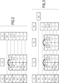
figure 2 , une représentation des piles protocolaires dans le plan de contrôle pour l'architecture de lafigure 1 , -
figure 3 , une représentation des piles protocolaires dans le plan usager pour l'architecture de lafigure 1 , -
figure 4 , une représentation schématique d'un exemple d'architecture réseau, -
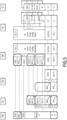
figure 5 , une représentation des piles protocolaires dans le plan de contrôle pour une première configuration de l'architecture de lafigure 4 dans un premier exemple, -
figure 6 , une représentation des piles protocolaires dans le plan usager pour la première configuration dans un premier exemple, -
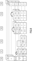
figure 7 , une représentation des piles protocolaires dans le plan de contrôle pour une deuxième configuration de l'architecture de lafigure 4 dans un premier exemple, -
figure 8 , une représentation des piles protocolaires dans le plan usager pour la deuxième configuration dans un premier exemple, -
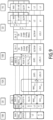
figure 9 , une représentation des piles protocolaires dans le plan de contrôle pour une troisième configuration de l'architecture de lafigure 4 dans un premier exemple, -
figure 10 , une représentation des piles protocolaires dans le plan usager pour la troisième configuration dans un premier exemple, -
figure 11 , une représentation des piles protocolaires dans le plan de contrôle pour une première configuration de l'architecture de lafigure 10 dans un deuxième exemple, -
figure 12 , une représentation des piles protocolaires dans le plan usager pour la première configuration dans un deuxième exemple, -
figure 13 , une représentation des piles protocolaires dans le plan de contrôle pour une deuxième configuration de l'architecture de lafigure 10 dans un deuxième exemple, -
figure 14 , une représentation des piles protocolaires dans le plan usager pour la deuxième configuration dans un deuxième exemple, -
figure 15 , une représentation des piles protocolaires dans le plan de contrôle pour une troisième configuration de l'architecture de lafigure 10 dans un deuxième exemple, -
figure 16 , une représentation des piles protocolaires dans le plan usager pour la troisième configuration dans un deuxième exemple, -
figure 17 , un ordinogramme d'un exemple de procédé de détermination de configurations, -
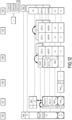
figures 18 à 23 , des exemples de graphes de réseaux, -
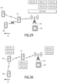
figures 24 à 30 , des exemples de couches utilisées lors de la mise en oeuvre du procédé de détermination, et -
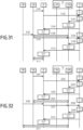
figures 31 et 32 , des schémas illustrant un mécanisme de configuration des couches, et -
figure 33 , un ordinogramme d'un exemple de procédé de détermination de configurations.
-
figure 1 , a schematic representation of an LTE network architecture according to the state of the art, -
figure 2 , a representation of the protocol stacks in the control plane for the architecture of thefigure 1 , -
Figure 3 , a representation of the protocol stacks in the user plane for the architecture of thefigure 1 , -
figure 4 , a schematic representation of an example of network architecture, -
figure 5 , a representation of the protocol stacks in the control plane for a first configuration of the architecture of theFigure 4 in a first example, -
Figure 6 , a representation of the protocol stacks in the user plane for the first configuration in a first example, -
Figure 7 , a representation of the protocol stacks in the control plane for a second configuration of the architecture of thefigure 4 in a first example, -
figure 8 , a representation of the protocol stacks in the user plane for the second configuration in a first example, -
Figure 9 , a representation of the protocol stacks in the control plane for a third configuration of the architecture of theFigure 4 in a first example, -
Figure 10 , a representation of the protocol stacks in the user plane for the third configuration in a first example, -
Figure 11 , a representation of the protocol stacks in the control plane for a first configuration of the architecture of theFigure 10 in a second example, -
Figure 12 , a representation of the protocol stacks in the user plane for the first configuration in a second example, -
Figure 13 , a representation of the protocol stacks in the control plane for a second configuration of the architecture of theFigure 10 in a second example, -
Figure 14 , a representation of the protocol stacks in the user plane for the second configuration in a second example, -
Figure 15 , a representation of the protocol stacks in the control plane for a third configuration of the architecture of theFigure 10 in a second example, -
Figure 16 , a representation of the protocol stacks in the user plane for the third configuration in a second example, -
Figure 17 , a flowchart of an example of a method for determining configurations, -
figures 18 to 23 , examples of network graphs, -
figures 24 to 30 , examples of layers used during the implementation of the determination method, and -
figures 31 and 32 , diagrams illustrating a layer configuration mechanism, and -
Figure 33 , a flowchart of an example of a method for determining configurations.
Pour l'ensemble des sigles et notions utilisées dans la description qui suit, le lecteur est invité à se reporter à la partie LEXIQUE.For all the acronyms and notions used in the following description, the reader is invited to refer to the GLOSSARY section.
La
Une telle architecture est une architecture classique 4G. Une telle architecture a fait l'objet de la normalisation 3GPP.Such an architecture is a classic 4G architecture. Such an architecture was the subject of 3GPP standardization.
La
L'architecture réseau comporte une pluralité d'entités agissant dans des zones Z1, Z2, Z3 distinctes. La première zone Z1 est la zone applicative, la deuxième zone Z2 est le coeur du réseau et la troisième zone Z3 est la zone de couverture et où la communication se fait par un moyen de communications sans-fils.The network architecture includes a plurality of entities acting in distinct zones Z1, Z2, Z3. The first zone Z1 is the application zone, the second zone Z2 is the heart of the network and the third zone Z3 is the coverage zone and where communication is done by means of wireless communications.
L'architecture réseau comporte une première entité 10, une deuxième entité 12, une troisième entité 14, une quatrième entité 16 et une cinquième entité 18.The network architecture comprises a
La première entité 10 est un eNodeB.The
Dans la suite, la première entité 10 est notée entité eNodeB.In the following, the
La deuxième entité 12 comporte deux parties, une première sous-entité 12A et une deuxième sous-entité 12B.The
La première sous-entité 12A de la deuxième entité 12 est un S-GW.The
Dans la suite, la première sous-entité 12A de la deuxième entité 12 est notée entité S-GW.In the following, the
La deuxième sous-entité 12B de la deuxième entité 12 est un P-GW.The
Dans la suite, la deuxième sous-entité 12B de la deuxième entité 12 est notée entité P-GW.In the following, the second sub-entity 12B of the
La troisième entité 14 est un serveur applicatif.The
La quatrième entité 16 est un MME.The
Le terme MME désigne une entité de contrôle de l'architecture du réseau LTE, mais l'homme de l'art voit bien que dans le contexte de la présente invention, une entité avec tout autre nom qui aurait les mêmes fonctions de contrôle du MME qui sont utilisées dans le contexte de cette invention peut convenir à l'implémentation de l'invention.The term MME designates an entity for controlling the architecture of the LTE network, but those skilled in the art can see that in the context of the present invention, an entity with any other name which would have the same control functions of the MME which are used in the context of this invention may be suitable for the implementation of the invention.
Dans la suite, la quatrième entité 16 est notée entité MME.In the following, the
La cinquième entité 18 est un terminal UE.The
Dans la suite, la cinquième entité 18 est notée terminal UE.In the following, the
L'architecture réseau est propre à fonctionner selon plusieurs voies. La voie montante désigne une communication du terminal UE vers entité eNodeB et la voie descendante une communication depuis l'entité eNodeB vers le terminal UE. La voie montante est souvent désignée par le terme anglais « uplink » alors que la voie descendante est nommée avec le terme anglais « downlink ».The network architecture is designed to operate in several ways. The uplink channel designates a communication from the UE terminal to the eNodeB entity and the downlink channel a communication from the eNodeB entity to the UE terminal. The upstream channel is often referred to by the English term “uplink” while the descending channel is named with the English term “downlink”.
Le fonctionnement de l'architecture de la
Dans la
De fait, pour cette architecture classique LTE, la normalisation 3GPP a défini un plan de contrôle (ou « Control Plane » en Anglais) et un plan usager (ou « User Plane » en Anglais). Le plan de contrôle est représenté à la
Il est à noter que la normalisation 3GPP a également défini une répartition en couches de la même manière que pour le modèle OSI, cette répartition en couches étant spécifique à la normalisation 3GPP. Cette répartition en couche ou sous-couche n'est pas abordée à ce stade pour simplifier la description. En outre, le terme de « couche » est systématiquement employé dans la suite pour désigner une couche ou une sous-couche, la notion de « sous-couche » et de « couche » dépendant du contexte. Plus de détails relatifs à cette répartition se trouvent dans la partie LEXIQUE.It should be noted that the 3GPP standardization has also defined a layering in the same way as for the OSI model, this layering being specific to the 3GPP standardization. This distribution into layers or sub-layers is not discussed at this stage to simplify the description. In addition, the term "layer" is systematically used in the following to designate a layer or a sub-layer, the notion of "sub-layer" and "layer" depending on the context. More details relating to this distribution can be found in the GLOSSARY section.
Dans la suite, il est décrit le fonctionnement de l'architecture en voie descendante. En utilisant la description du fonctionnement de l'architecture en voie descendante, l'homme du métier peut dériver d'une manière similaire le fonctionnement de l'architecture en voie montante.In the following, the operation of the downstream architecture is described. Using the description of the operation of the downstream architecture, those skilled in the art can derive the operation of the upstream architecture in a similar manner.
Dans la
Dans la
Au niveau du terminal UE, les données traversent une couche PHY, une couche MAC, une couche RLC, une couche PDCP, une couche RRC et une couche NAS.At the UE terminal, data passes through a PHY layer, a MAC layer, an RLC layer, a PDCP layer, an RRC layer and a NAS layer.
Lors de la traversée des couches, des opérations ont lieu, ces opérations correspondant à l'intitulé de la couche traversée. Les opérations sont, par exemple, des modifications des en-têtes et d'encapsulation/décapsulation de chaque donnée.When crossing layers, operations take place, these operations corresponding to the title of the layer crossed. The operations are, for example, modifications of the headers and encapsulation/decapsulation of each piece of data.
Dans la
Au niveau de l'entité S-GW, les données traversent une couche L1, une couche L2, une couche UDP/IP, une couche GTP-U puis une couche UDP/IP, une couche L2 et une couche L1.At the S-GW entity, data passes through an L1 layer, an L2 layer, a UDP/IP layer, a GTP-U layer and then a UDP/IP layer, an L2 layer, and an L1 layer.
Au niveau de l'eNodeB, pour le plan usager, les données traversent une couche L1, une couche L2, une couche UDP/IP, une couche GTP-U puis une couche PDCP, une couche RLC, une couche MAC et une couche PHY.At the eNodeB level, for the user plane, the data passes through an L1 layer, an L2 layer, a UDP/IP layer, a GTP-U layer then a PDCP layer, an RLC layer, a MAC layer and a PHY layer .
Au niveau du terminal UE, les données traversent une couche PHY, une couche MAC, une couche RLC, une couche PDCP, une couche IP et une couche applicative.At the UE terminal, the data passes through a PHY layer, a MAC layer, an RLC layer, a PDCP layer, an IP layer and an application layer.
Il est à remarquer qu'en fonction du service, les paquets pourraient être générés aussi par la couche applicative d'un autre terminal dans le même réseau ou aussi dans d'autres réseaux si des passerelles existent.It should be noted that depending on the service, the packets could also be generated by the application layer of another terminal in the same network or also in other networks if gateways exist.
Il est à noter, par exemple, les fonctions PDCP dans le plan usager comporte l'encryptage et le décryptage, la compression et décompression RoHC de l'en-tête des paquets en provenance des couches supérieures (e.g. depuis IP) (aussi appelé « RoHC header compression »), la numérotation des séquences (aussi appelé « séquence numbering ») et l'enlèvement des paquets dupliqués (aussi appelé « duplicate removal »).It should be noted, for example, the PDCP functions in the user plane include encryption and decryption, RoHC compression and decompression of the header of packets coming from higher layers (e.g. from IP) (also called " RoHC header compression"), sequence numbering (also called "sequence numbering") and the removal of duplicate packets (also called "duplicate removal").
Par contraste, dans le plan de contrôle, les fonctions PDCP comprennent l'encryptage et le décryptage, la protection en intégrité, la numérotation des séquences et l'enlèvement des paquets dupliqués.In contrast, in the control plane, PDCP functions include encryption and decryption, integrity protection, sequence numbering, and removal of duplicate packets.
Il y a une instance PDCP par « radio bearer ». Le « radio bearer » est similaire à un canal logique pour acheminer des données utilisateur.There is one PDCP instance per “radio bearer”. The radio bearer is similar to a logical channel for carrying user data.
Un exemple d'architecture réseau est représenté sur la
Les éléments communs avec l'architecture réseau de la
Contrairement au cas de la
L'entité 10A est un point d'accès simplifié, 10A peut être, par exemple, un RRH ou un TP.The
Le point d'accès est simplifié en ce sens qu'une partie des couches seulement sont implémentées par l'entité RRH ou TP.The access point is simplified in the sense that only part of the layers are implemented by the RRH or TP entity.
Plus précisément, l'entité TP implémente des couches inférieures au niveau 3, de préférence strictement inférieures à 3, et l'entité RRH implémente des couches inférieures au niveau 2, de préférence strictement inférieures à 2.More precisely, the TP entity implements layers lower than level 3, preferably strictly lower than 3, and the RRH entity implements layers lower than level 2, preferably strictly lower than 2.
Ainsi, selon l'exemple proposé, l'entité 10A implémente d'une manière complète au moins l'une des couches suivantes : PHY, MAC, RLC et PDCP.Thus, according to the example proposed, the
Selon un autre mode de réalisation, l'entité 10A implémente des couches de manière partielles, par exemple la couche PHY et une ou plusieurs sous-couches de la couche L2 par exemple la sous-couche MAC seulement ou les sous-couches MAC et RLC.According to another embodiment, the
La VM est une machine virtuelle.The VM is a virtual machine.
La VM a le rôle d'implémenter une partie ou toutes les couches supérieures. Par exemple, la VM est propre à émettre des couches supérieures au niveau 2, de préférence strictement supérieurs à 2.The VM has the role of implementing part or all of the upper layers. For example, the VM is capable of transmitting layers greater than level 2, preferably strictly greater than 2.
A titre d'illustration, selon un cas particulier, la VM est propre à émettre de manière complète ou partielle une ou plusieurs couches de niveau 2 comme la couche MAC, la couche RLC ou la couche PDCP et une ou plusieurs couches de niveau 3 ou supérieurs comme RRC ou NAS.By way of illustration, according to a particular case, the VM is capable of completely or partially transmitting one or more level 2 layers such as the MAC layer, the RLC layer or the PDCP layer and one or more level 3 layers or superiors such as RRC or NAS.
La VM a, dans certains cas les fonctionnalités d'un BBU (voir définition dans la partie LEXIQUE).The VM has, in certain cases, the functionalities of a BBU (see definition in the GLOSSARY section).
Dans la
En variante, la VM est exécutée sur des machines physiques (calculateurs, ou autre machine avec des ressources de calcul et de stockage aptes à implémenter la VM) qui sont géographiquement proches ou co-localisées avec l'entité émetteur/récepteur radio 10A ou alors est exécutée dans l'entité émetteur/récepteur radio 10A si la machine physique où l'entité émetteur/récepteur radio 10A est implémenté a suffisamment de ressources de calcul et de mémoire (architecture de type « edge» ou décentralisée,où les ressources sont plutôt en bord du réseau).Alternatively, the VM is executed on physical machines (computers, or other machine with calculation and storage resources capable of implementing the VM) which are geographically close or co-located with the radio transmitter/
Contrairement au cas de la
La cinquième entité UE 18A est notée terminal UE1 dans la suite et la sixième entité UE 18B est notée terminal UE2.The
Les deux terminaux UE1 et UE2 font partie d'une quatrième zone Z4 qui est une zone hors de couverture.The two terminals UE1 and UE2 are part of a fourth zone Z4 which is a zone out of coverage.
L'architecture comporte également une septième entité UE-R 20.The architecture also includes a seventh UE-
L'UE-R 20 est une entité relais notée le relais UER dans la suite.The UE-
L'architecture comporte en outre une huitième entité 22.The architecture also includes an
La huitième entité 22 est un contrôleur, noté contrôleur CC dans la suite.The
Dans l'exemple représenté, le contrôleur CC est unique.In the example shown, the CC controller is unique.
La VM présente une configuration contrôlée par le contrôleur CC.The VM presents a configuration controlled by the CC controller.
En variante, le contrôleur CC comporte deux parties : une partie qui implémente des fonctionnalités pour des applications lentes et une autre partie qui implémente des fonctionnalités pour des applications en temps réel.Alternatively, the CC controller has two parts: one part that implements functionality for slow applications and another part that implements functionality for real-time applications.
Selon les cas, les deux parties du contrôleur CC sont deux entités distinctes ou colocalisées.Depending on the case, the two parts of the CC controller are two distinct or co-located entities.
Dans le schéma de la
Le fonctionnement de l'architecture de la
Il est adopté les conventions suivantes dans les schémas de plan usager et de plan de contrôle : X désigne par exemple un protocole de type SCTP ; Y désigne par exemple un protocole de type UDP ; L2t est un protocole de type L2 utilisé entre la VM et l'entité TP (ou RRH), par exemple L2 Ethernet ; L1t est un protocole de type L1 utilisé entre la VM et l'entité TP (ou RRH), par exemple L1 Ethernet ; L0t est un protocole de type CPRI, OBSAI ou ORI utilisé entre la VM et l'entité RRH. Dans ce cas-là des I/Q PHY sont directement transmis sur L0t. Ces conventions sont notamment utilisées dans le texte. Pour les exemples qui suivent dans les
En plus, si une couche est mise entre deux parenthèses, cela signifie que le protocole associé est optionnel, à savoir qu'il est utilisé ou non. Par exemple, une couche NAS avec NAS entre parenthèse implique que le protocole est mis en oeuvre ou non. Selon un autre exemple, une couche PDCP avec PDCP entre parenthèse implique que le protocole est mis en oeuvre ou non. Un autre exemple concerne les couches X et Y, ou X/IP et Y/IP.In addition, if a layer is put between two parentheses, this means that the associated protocol is optional, i.e. it is used or not. For example, a NAS layer with NAS in parentheses implies that the protocol is implemented or not. In another example, a PDCP layer with PDCP in parentheses implies that the protocol is implemented or not. Another example is layers X and Y, or X/IP and Y/IP.
En plus, si un ensemble de couches est superposé, cela signifie qu'il peut avoir plusieurs couches qui fonctionnent en parallèle, ou qu'il peut avoir plusieurs entités distincts qui peuvent fonctionner en parallèle (comme par exemple plusieurs MME 16 qui sont connectés au même CC 22, parce que un UER 20 et/ou parce que un ou plusieurs UE 18, 18A ou 18B sont connectés à des MMEs différents - potentiellement ils sont gérés par des MMEs différents).In addition, if a set of layers is superimposed, this means that it can have several layers which operate in parallel, or that it can have several distinct entities which can operate in parallel (such as for example
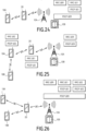
Les
Dans l'exemple de la
Au niveau du contrôleur CC, les données traversent une couche L1, une couche L2, une couche IP, une couche SCTP, une couche S1-AP et une couche NAS puis une couche Ctr. Layer (couche pour le plan de contrôle), couche qui est responsable de la transmission du plan de contrôle qui traverse CC vers la VM, une couche SCTP/IP et une couche L2/L1. Concernant la couche « Ctr. Layer », elle peut utiliser un protocole de type X2-AP ou S1-AP qui sont normalement utilisés sur les interfaces X2-C ou S1-C/S1-MME. Une fonction « Ctr. F. » (serveur) peut être présente pour contrôler la configuration de la couche Ctr. Layer entre le CC et la VM. A la différence de « Ctr. Layer » qui est une couche, « Ctr. F. » est donc une fonction responsable de la mise en place du protocole à utiliser pour « Ctr. Layer », et il s'agit donc d'une fonction de niveau supérieur.At the CC controller, data passes through an L1 layer, an L2 layer, an IP layer, an SCTP layer, an S1-AP layer and a NAS layer and then a Ctr layer. Layer, layer which is responsible for transmitting the control plane which passes through CC to the VM, an SCTP/IP layer and an L2/L1 layer. Regarding the “Ctr. Layer”, it can use an X2-AP or S1-AP type protocol which are normally used on X2-C or S1-C/S1-MME interfaces. A “Ctr. F.” (server) may be present to control the configuration of the Ctr layer. Layer between the CC and the VM. Unlike “Ctr. Layer” which is a layer, “Ctr. F.” is therefore a function responsible for setting up the protocol to be used for “Ctr. Layer", and therefore it is a higher level function.
Au niveau de la VM, pour le plan de contrôle, les données traversent une couche L2/L1, une couche SCTP/IP, une couche Ctr. Layer, puis une couche NAS, une couche RRC, une couche PDCP, une sous-couche NAS R, une couche RRC R, une couche PDCP R (pas forcement dans cette ordre comme exemplifié plus tard par les
Au niveau de l'entité TP, les données traversent les couches L 1t et L2t, une couche (X/IP), puis une couche MAC et une couche PHY.At the TP entity level, the data passes through layers L 1t and L2t, a layer (X/IP), then a MAC layer and a PHY layer.
Au niveau du relais UER, pour le plan de contrôle à la destination de l'UER les données traversent une couche PHY, une couche MAC, une couche RLC R, une couche PDCP R, une couche RRC R, une couche NAS R; et pour le plan de contrôle à la destination de l'UE1 les données traversent une couche PHY, une couche MAC, une couche RLC R, une couche PDCP R puis une couche L2 générique, puis une couche générique L1.At the UER relay level, for the control plane at the destination of the UER the data passes through a PHY layer, a MAC layer, an RLC R layer, a PDCP R layer, an RRC R layer, a NAS R layer; and for the control plane at the destination of UE1 the data passes through a PHY layer, a MAC layer, an RLC R layer, a PDCP R layer then a generic L2 layer, then a generic L1 layer.
Au niveau du terminal UE1, les données traversent une couche générique L1, une couche générique L2, une couche PDCP, une couche RRC et une couche NAS.At the terminal UE1, the data passes through a generic L1 layer, a generic L2 layer, a PDCP layer, an RRC layer and a NAS layer.
Dans l'exemple de la
Au niveau de la VM, sur le plan usager, les données traversent une couche L1, une couche L2, une couche UDP/IP, une couche GTP-U, une couche PDCP, une couche PDCP R, une couche RLC R, des couches (Y/IP) et L2t/L1t. Cela peut être implémenté d'une manière partielle. Plus précisément, au niveau de la VM, les données à la destination de UER traversent une couche L1, une couche L2, une couche UDP/IP, une couche GTP-U, une couche PDCP R, une couche RLC R, des couches (Y/IP) et L2t/L1t, et les données à la destination de UE 18A (UE1) traversent une couche L1, une couche L2, une couche UDP/IP, une couche GTP-U, une couche PDCP, une couche PDCP R, une couche RLC R, des couches (Y/IP) et L2t/L1t.At the VM level, on the user level, the data passes through an L1 layer, an L2 layer, a UDP/IP layer, a GTP-U layer, a PDCP layer, a PDCP R layer, an RLC R layer, layers (Y/IP) and L2t/L1t. This can be implemented in a partial way. More precisely, at the VM level, the data at the destination of UER passes through an L1 layer, an L2 layer, a UDP/IP layer, a GTP-U layer, a PDCP R layer, an RLC R layer, layers ( Y/IP) and L2t/L1t, and the data to the destination of
Au niveau de l'entité TP, sur le plan usager, les données traversent des couches L1t, L2t, puis une couche (Y/IP), une couche MAC et une couche PHY.At the TP entity level, on the user level, the data passes through layers L1t, L2t, then a layer (Y/IP), a MAC layer and a PHY layer.
Au niveau du relais UER, les données qui sont adressées au relais UER même traversent une couche PHY, une couche MAC, une couche RLC R, une couche PDCP R, une couche IP, une couche applicative. Au niveau du relais UER, les données qui sont adressées à l'entité 18A (terminal UE1) sous couverture radio du relais UER traversent une couche PHY, une couche MAC, une couche RLC R, une couche PDCP R, puis une couche générique L2 et une couche générique L1.At the UER relay level, the data which is addressed to the UER relay itself passes through a PHY layer, a MAC layer, an RLC R layer, a PDCP R layer, an IP layer, an application layer. At the UER relay level, the data which is addressed to the
Au niveau du terminal UE1, les données traversent une couche générique L1, une couche générique L2, une couche PDCP, une couche IP et une couche applicative.At the terminal UE1, the data passes through a generic L1 layer, a generic L2 layer, a PDCP layer, an IP layer and an application layer.
Dans ce cas, la couche PDCP UE est encapsulée dans une couche PDCP UE-R. Le relais UER relaie l'information vers le terminal UE1 sans la décoder/décrypter ou la déchiffrer.In this case, the PDCP UE layer is encapsulated in a PDCP UE-R layer. The UER relay relays the information to the UE1 terminal without decoding/decrypting or deciphering it.
En outre, il est à noter que l'entité 18 A hors de la zone est contrôlé par la VM à l'aide des sous-couches RRC ou NAS (voir aussi
Les
Les mêmes éléments que pour le plan usager et le plan de contrôle de la première configuration s'appliquent pour le plan usager et le plan de contrôle selon la deuxième configuration. Seules les différences sont détaillées dans ce qui suit.The same elements as for the user plane and the control plane of the first configuration apply for the user plane and the control plane according to the second configuration. Only the differences are detailed in the following.
Dans le plan de contrôle sur la
Au niveau du relais UER, les couches PDCP R, RRC R et NAS R ne sont pas traversées et/ou utilisées.At the UER relay level, the PDCP R, RRC R and NAS R layers are not crossed and/or used.
Enfin, au niveau du premier terminal UE, les données traversent une couche PDCP UE. Dans le plan usager sur la
Similairement, au niveau du relais UER, la traversée par les données des couches RLC R, une couche PDCP R, une couche IP, une couche applicative est remplacée par la traversée d'une unique couche RLC R. Le relais UER relaie l'information vers le terminal UE1 sans forcément le décoder/décrypter ou le déchiffrer (s'il ne connaît pas la configuration de la couche PDCP UE).Similarly, at the UER relay level, the crossing by the data of the RLC R layers, a PDCP R layer, an IP layer, an application layer is replaced by the crossing of a single RLC R layer. The UER relay relays the information towards the terminal UE1 without necessarily decoding/decrypting or decrypting it (if it does not know the configuration of the PDCP UE layer).
Au niveau du terminal UE1, il y a une couche PDCP UE qui sert pour la communication bout-en-bout entre UE1 et VM. Dans ce cas, la couche PDCP UE n'est pas encapsulée dans la couche PDCP du relais UER.At the UE1 terminal, there is a UE PDCP layer which is used for end-to-end communication between UE1 and VM. In this case, the PDCP UE layer is not encapsulated in the PDCP layer of the UER relay.
En outre, il est à noter que le terminal UE1 hors de la zone est contrôlé par la VM à l'aide des couches RRC ou NAS (voir
Les
Les mêmes éléments que pour le plan usager et le plan de contrôle de la deuxième configuration s'appliquent pour le plan usager et le plan de contrôle selon la troisième configuration. Seules les différences sont détaillées dans ce qui suit.The same elements as for the user plane and the control plane of the second configuration apply for the user plane and the control plane according to the third configuration. Only the differences are detailed in the following.
Dans le plan de contrôle, au niveau de la VM sur la
En d'autres mots, dans le plan de contrôle de la
Au niveau du relais UER, dans le plan de contrôle sur la
Au niveau du terminal UE1, les données traversent une couche générique L1, une couche générique L2, une couche (PDCP), une couche RRC et une couche NAS. Dans ce contexte, les couches RRC et NAS d'un terminal UE 18 A (UE1) sont gérées par UER.At the terminal UE1, the data passes through a generic L1 layer, a generic L2 layer, a (PDCP) layer, an RRC layer and a NAS layer. In this context, the RRC and NAS layers of a
Ce n'est pas représenté sur la
Dans le plan usager, au niveau de la VM sur la
Au niveau du relais UER, dans le plan usager sur la
Le relais UER peut utiliser une fonction Rel. f. (« Relaying function ») pour filtrer les paquets reçus depuis le serveur applicatif vers sa propre application ou vers la couches nécessaire pour une transmission vers UE hors-de-couverture pour la couche application d'un UE hors-de-couverture ou un autre UE relayé par un UE hors-de-couverture (voir
Pour la voie descendante, sur le plan contrôle de la
Pour la voie montante, sur le plan de contrôle de la
Pour la voie montante, sur le plan usager de la
Dans une implémentation potentielle, la fonction Rel. f. au niveau VM et/ou UER (et surtout sur le plan de contrôle) peut être assimilée ou intégrée à la fonction de control « Ctr. f. ». Cependant le rôle de la fonction Rel. f. est plutôt sur le plan usager que sur le plan de contrôle, et elle peut être vue comme une fonction de routage. Dans une situation multi-hop cette fonction est essentielle pour relayer les mesures sur le plan usager depuis l'UE 18 A vers la VM 10B, à travers l'UER 20.In one potential implementation, the Rel. f. at the VM and/or UER level (and especially on the control plane) can be assimilated or integrated into the control function “Ctr. f. ". However the role of the Rel function. f. is more on the user plane than on the control plane, and it can be seen as a routing function. In a multi-hop situation this function is essential to relay measurements on the user plane from
Au niveau du terminal UE1, on utilise optionnellement une couche PDCP UE aussi appelé (PDCP), pour une utilisation directe entre UE et UER (et qui joue le rôle d'une couche PDCP qui normalement se trouve entre un terminal UE et une eNB classique).At the UE1 terminal, we optionally use a UE PDCP layer also called (PDCP), for direct use between UE and UER (and which plays the role of a PDCP layer which is normally found between a UE terminal and a classic eNB ).
Dans cette configuration, c'est le relais UER qui met en oeuvre le contrôle des terminaux UE hors de la zone de couverture. Le relais UER est pourvu de la capacité de décrypter les informations vers le terminal UE.In this configuration, it is the UER relay which implements the control of the UE terminals outside the coverage area. The UER relay is provided with the capacity to decrypt the information to the UE terminal.
En variante, les informations UE sont encodées au niveau de l'application et le relais UER n'a pas la capacité de les décrypter.Alternatively, the UE information is encoded at the application level and the UER relay does not have the ability to decrypt it.
Une quatrième configuration dite de « Broadcast opération » est également possible. Le terme « Broadcast » renvoie au cas d'au moins un terminal UE attaché directement au point d'accès réseau, soit une configuration sans bond. Dans un mode de diffusion, plusieurs terminaux UE peuvent recevoir la même information (voix, données, video.. etc).A fourth configuration called “Broadcast operation” is also possible. The term “Broadcast” refers to the case of at least one UE terminal attached directly to the network access point, i.e. a hop-free configuration. In a broadcast mode, several UE terminals can receive the same information (voice, data, video, etc.).
Les mêmes éléments que pour le plan usager et le plan de contrôle de la troisième configuration s'appliquent pour le plan usager et le plan de contrôle selon la quatrième configuration. Seules les différences sont détaillées dans ce qui suit.The same elements as for the user plane and the control plane of the third configuration apply for the user plane and the control plane according to the fourth configuration. Only the differences are detailed in the following.
Dans le plan usager, au niveau de la VM, les couches RLC R, PDCP R, RRC R et NAS R sont remplacées par trois couches RLC, RRC et NAS.In the user plane, at the VM level, the RLC R, PDCP R, RRC R and NAS R layers are replaced by three layers RLC, RRC and NAS.
En outre, dans ce cas, il n'y a pas de relais UER servant de relais.Furthermore, in this case there is no EBU relay serving as a relay.
Chaque entité parmi le terminal UE1, le terminal UE2 et le relais UER reçoit les paquets en provenance de la pile protocolaire formée par les couches PHY, MAC, RLC, RRC et NAS.Each entity among the terminal UE1, the terminal UE2 and the relay UER receives the packets coming from the protocol stack formed by the PHY, MAC, RLC, RRC and NAS layers.
Dans le plan de contrôle, au niveau de la machine virtuelle 10B, les couches RLC R et PDCP R sont remplacées par une couche RLC.In the control plane, at the level of the
Chaque entité parmi le terminal UE1, le terminal UE2 et le relais UER reçoit les couches PHY, MAC, RLC, IP et App.Each entity among the terminal UE1, the terminal UE2 and the relay UER receives the PHY, MAC, RLC, IP and App layers.
Une cinquième configuration dite de « Broadcast opération using eMBMS» est possible.A fifth configuration called “Broadcast operation using eMBMS” is possible.
Les mêmes éléments que pour le plan usager et le plan de contrôle de la quatrième configuration s'appliquent pour le plan usager et le plan de contrôle selon la cinquième configuration. Seules les différences sont détaillées dans ce qui suit.The same elements as for the user plane and the control plane of the fourth configuration apply for the user plane and the control plane according to the fifth configuration. Only the differences are detailed in the following.
Dans le plan usager, les couches S1-AP et NAS sont remplacées par les couches SCTP et M3-AP à la fois dans l'entité MME et dans contrôleur CC.In the user plane, the S1-AP and NAS layers are replaced by the SCTP and M3-AP layers both in the MME entity and in the CC controller.
En outre, il n'y a pas d'instanciation de couche NAS et donc de transmission à travers ladite couche.In addition, there is no instantiation of the NAS layer and therefore no transmission through said layer.
Ces différences se transposent aisément dans le plan de contrôle qui n'est pas plus détaillé.These differences are easily transposed into the control plan which is not more detailed.
Une sixième configuration permet d'avoir un équivalent de la configuration « Multi-Hop relaying » (notamment illustrées par les
Il est possible de transposer les configurations précédentes avec d'autres alternatives. Par exemple, selon un mode de réalisation, l'entité 10A transmet uniquement les couches PHY et pas la couche MAC (voir les
Selon un autre mode de réalisation, les PDUs en provenance de la sous-couche LTE RLC (et/ou LTE MAC) sont encapsulées dans des PDUs traversant une sous-couche MAC Ethernet et transmis avec l'entité 10A (RRH ou TP). Selon un autre mode de réalisation, la sous-couche PHY/CPRI est remplacée par une sous-couche Lt2/Lt1 fonctionnant avec Ethernet.According to another embodiment, the PDUs coming from the LTE RLC sublayer (and/or LTE MAC) are encapsulated in PDUs crossing an Ethernet MAC sublayer and transmitted with the 10A entity (RRH or TP). According to another embodiment, the PHY/CPRI sublayer is replaced by an Lt2/Lt1 sublayer operating with Ethernet.
La
Pour cela, le contrôleur CC utilise des graphes de réseau. Les
De bas en haut, à travers une multitude de couche protocolaire on peut mesurer des paramètres comme le bruit, l'interférence, puissance, connectivité (voir
Le procédé comporte une pluralité d'étapes notées avec les signes de références E0 à E7 et C1 à C3.The process comprises a plurality of steps denoted with the reference signs E0 to E7 and C1 to C3.
Les étapes E1, E3, E4 et E7 interagissent avec une base de données notée DB. De manière plus générale, il est interagi dans les étapes E1, E3, E4 et E7 avec tout moyen de sauvegarder et exposer l'information nécessaire.Steps E1, E3, E4 and E7 interact with a database denoted DB. More generally, it is interacted in steps E1, E3, E4 and E7 with any means of saving and exposing the necessary information.
La base de données DB permet de collecter, d'actualiser et de sauvegarder l'information relative au moins une entité de l'architecture réseau.The DB database makes it possible to collect, update and save information relating to at least one entity of the network architecture.
Par exemple, l'actualisation et la collecte d'information se fait à travers une APl.For example, updating and collecting information is done through an APl.
A l'étape E0 d'initialisation, chaque terminal UE est enregistré et les besoins en termes de service du terminal UE sont également enregistrés (potentiellement dans une DB).In initialization step E0, each UE terminal is recorded and the service requirements of the UE terminal are also recorded (potentially in a DB).
L'enregistrement est, par exemple, mis en oeuvre par le contrôleur CC qui récupère les informations grâce à la VM, la VM jouant alors le rôle d'une station de base.The recording is, for example, implemented by the controller CC which recovers the information using the VM, the VM then playing the role of a base station.
Selon les cas, les besoins en termes de service (voir par exemple aussi TS 23.203 avec les indicateurs de classe de QoS, ce qu'on appelle QCI ou QoS Class Identifiers) sont, par exemple, les besoins en BER (Bit Error Rate), en PER (Packet Error Rate), en priorité, les besoins en latence, en RSRP, RSRQ ou en débit.Depending on the case, the needs in terms of service (see for example also TS 23.203 with the QoS class indicators, what we call QCI or QoS Class Identifiers) are, for example, the needs in BER (Bit Error Rate) , in PER (Packet Error Rate), in priority, the needs in latency, in RSRP, RSRQ or in throughput.
L'enregistrement est, par exemple, mis en oeuvre à l'aide d'un relais UER ou un terminal UE devenant un relais UER.The recording is, for example, implemented using a UER relay or a UE terminal becoming a UER relay.
Par exemple, il est supposé qu'un deuxième terminal UE2 entre dans l'architecture réseau.For example, it is assumed that a second terminal UE2 enters the network architecture.
A la première étape E1 de génération, il est généré un graphe de connectivité dans la base de données DB.At the first generation step E1, a connectivity graph is generated in the DB database.
La génération est, selon les cas, une création ou une actualisation.Generation is, depending on the case, a creation or an actualization.
Les
Selon un autre exemple, au lieu de mesurer le SNR, il est possible de mesurer la puissance utilisée, la valeur du bruit ou la valeur de l'interférence, ou une valeur binaire (pour dire connecté ou pas connecté) ou la valeur d'autres métriques comme le CQI défini dans le standard 3GPP et qui représente une efficacité spectrale associé au lien, ou tout autre métrique qui donne une mesure de qualité du lien.According to another example, instead of measuring the SNR, it is possible to measure the power used, the noise value or the interference value, or a binary value (to say connected or not connected) or the value of other metrics such as the CQI defined in the 3GPP standard and which represents a spectral efficiency associated with the link, or any other metric which gives a measure of link quality.
Selon l'exemple proposé avec le deuxième terminal UE2, l'architecture réseau voit que le premier terminal UE1 connaît l'existence du deuxième terminal UE2, qui se connecte à travers le premier terminal UE1, mais la configuration du premier terminal UE1 en relais n'est pas encore finalisée à ce stade. Seul le graphe de connectivité, c'est-à-dire la topologie, est connu.According to the example proposed with the second terminal UE2, the network architecture sees that the first terminal UE1 knows the existence of the second terminal UE2, which is connects through the first terminal UE1, but the configuration of the first terminal UE1 as a relay is not yet finalized at this stage. Only the connectivity graph, i.e. the topology, is known.
A l'étape de choix E2, il est choisi une configuration parmi les cinq configurations étudiées précédemment.At the choice step E2, a configuration is chosen from the five configurations studied previously.
Selon un autre exemple, à l'étape de choix E2, le choix est effectué parmi moins de configurations, notamment trois, et par exemple la première configuration, la deuxième configuration ou la troisième configuration. Dans un tel cas, les étapes E5 et E6 ne sont pas mises en oeuvre (ou elles sont éventuellement incorporées aux autres étapes ou comparaisons qui les suivent ou le précèdent).According to another example, in the choice step E2, the choice is made from fewer configurations, in particular three, and for example the first configuration, the second configuration or the third configuration. In such a case, steps E5 and E6 are not implemented (or they are possibly incorporated into the other steps or comparisons which follow or precede them).
Selon un autre exemple, il est également possible de regrouper des étapes, par exemple E4 et E5, ou que la sortie du comparateur C3 (et donc la flèche entre C3 et E1) soit directement utilisée comme entrée du comparateur C1 (et donc une autre flèche entre C3 et C1). Il est également possible que dans cet exemple l'étape E6 et/ou E7 soit incorporée à la comparaison C3. Si aucune configuration n'est considérée comme bénéfique pour le système au niveau C3, l'algorithme peut directement passer à l'étape C1 (et donc sans forcément effectuer les étapes E1 et/ou E2).According to another example, it is also possible to group steps, for example E4 and E5, or for the output of comparator C3 (and therefore the arrow between C3 and E1) to be directly used as an input to comparator C1 (and therefore another arrow between C3 and C1). It is also possible that in this example step E6 and/or E7 is incorporated into comparison C3. If no configuration is considered beneficial for the system at level C3, the algorithm can go directly to step C1 (and therefore without necessarily carrying out steps E1 and/or E2).
Il est supposé, à titre d'exemple, que le contrôleur CC choisit la troisième configuration.It is assumed, for example, that the CC controller chooses the third configuration.
A l'étape de test C1, il est testé si un nouvel utilisateur a effectué un enregistrement.In test step C1, it is tested whether a new user has made a registration.
Si un nouvel utilisateur est enregistré, la topologie de l'architecture est modifiée et l'étape E1 de génération est à nouveau mise en oeuvre.If a new user is registered, the topology of the architecture is modified and generation step E1 is implemented again.
En l'absence de nouvel utilisateur, la deuxième étape E3 de génération est mise en oeuvre.In the absence of a new user, the second generation step E3 is implemented.
L'exemple des
A l'étape de comparaison C2, il est déterminé si un basculement vers un autre émetteur que celui choisi à l'étape E2 de choix est souhaitable.In the comparison step C2, it is determined whether a switch to another transmitter than that chosen in the choice step E2 is desirable.
En variante, un tel basculement est choisi sur la base d'autres paramètres, comme des informations de latence, la qualité de service ou le débit.Alternatively, such failover is chosen based on other parameters, such as latency information, quality of service or throughput.
A titre d'exemple, il est supposé que le seul basculement possible est entre l'autre terminal UE et le relais UER ou réciproquement.For example, it is assumed that the only possible switchover is between the other terminal UE and the relay UER or vice versa.
Pour déterminer l'opportunité d'un tel basculement, il est comparé la qualité de la transmission entre les deux terminaux UE et entre le terminal UE et le relais UER.To determine the advisability of such a switchover, the quality of the transmission between the two terminals UE and between the terminal UE and the relay UER is compared.
Un critère de comparaison est, selon un cas particulier, la puissance transmise.A comparison criterion is, depending on a particular case, the transmitted power.
Selon un exemple plus raffiné, pour éviter les problèmes de basculement consécutif ou les effets de « ping-pong » qui vont avec ou les connexions/déconnexions/reconnexions consécutives au même point d'accès (UE, UER, eNB, VM)) ou aux différents points d'accès, la comparaison est mise en oeuvre pendant une durée prédéterminée et peut utiliser également des paramètres comme, par exemple, hystérésis et offset (comme par exemple en TS 36.331).According to a more refined example, to avoid consecutive failover problems or the "ping-pong" effects that go with or consecutive connections/disconnections/reconnections to the same access point (UE, UER, eNB, VM)) or at the different access points, the comparison is carried out for a predetermined duration and can also use parameters such as, for example, hysteresis and offset (as for example in TS 36.331).
Selon un autre exemple, un schéma avec une implémentation potentielle pour l'étape de comparaison C2 est mise en oeuvre dans la
Les éléments 31d, 32d et 33d sont des DBs qui alimentent en permanence les comparateurs 331c, 332c et 333c avec des informations 331i, 332i, 333i concernant la puissance mesurée, la qualité du lien comme e.g. RSRP, RSRQ, des informations sur la sélection de relais et les options disponibles comme autres points d'accès potentiels 331i, ou concernant la latence ou des informations sur le nombre de bonds 332i, ou des information concernant le débit nécessaire pour effectuer per service et per utilisateur, équipement ou entité 333i. En plus de ces éléments, le module 338e est responsable de la sélection ou/et la ré-sélection d'un autre point d'accès (UE, UER, eNB) pour une autre configuration potentielle.The
Lorsqu'il est déterminé qu'un basculement est souhaitable, l'étape E4 de basculement est mise en oeuvre alors que lorsqu'il est déterminé qu'un basculement n'est pas souhaitable, l'étape E6 de vérification est mise en oeuvre.When it is determined that a switchover is desirable, the switchover step E4 is implemented while when it is determined that a switchover is not desirable, the verification step E6 is implemented.
Supposons qu'un basculement depuis le terminal UE2 vers le relais UER est souhaité, ce basculement est mis en oeuvre lors de l'étape E4 de basculement.Suppose that a switchover from the terminal UE2 to the relay UER is desired, this switchover is implemented during the switchover step E4.
Il est ensuite mis en oeuvre une troisième étape E5 de génération, il est généré un graphe de latence comme illustré par les
La création ou l'actualisation du graphe de latence prend en compte le nombre de basculements consécutifs, la perte temporaire de la communication et la latence bout-en-bout entre des différents éléments.The creation or updating of the latency graph takes into account the number of consecutive switches, the temporary loss of communication and the end-to-end latency between different elements.
Dans l'exemple illustré, la latence diminue pour le terminal UE2 puisque le terminal UE2 est connecté directement au relais UER.In the example illustrated, the latency decreases for the terminal UE2 since the terminal UE2 is connected directly to the relay UER.
Il est alors à nouveau mis en oeuvre la première étape E1 de génération pour actualiser le graphe de connectivité.The first generation step E1 is then implemented again to update the connectivity graph.
Dans l'exemple illustré, le terminal UE1 est relié au relais UER, le relais UER étant également relié au terminal UE2 et à l'entité VM.In the example illustrated, the terminal UE1 is connected to the relay UER, the relay UER also being connected to the terminal UE2 and to the entity VM.
L'étape E2 de choix est à nouveau mise en oeuvre, le contrôleur CC choisissant la première configuration. Le contrôleur CC configure alors la VM pour que la première configuration soit mise en oeuvre.The choice step E2 is implemented again, the controller CC choosing the first configuration. The CC controller then configures the VM so that the first configuration is implemented.
Dans le cas où l'étape E6 de vérification est mise en oeuvre (pas de basculement), il est alors vérifié si la configuration peut être améliorée.In the case where verification step E6 is implemented (no switchover), it is then checked whether the configuration can be improved.
Cela permet de vérifier une configuration multi-hop peut être transformée en configuration single-hop et ensuite en mode diffusion si cela n'est pas déjà résolu par le basculement (car le lien n'était pas si mauvais). Il s'agit d'une vérification pour effectuer une optimisation supplémentaire. Par exemple, le contrôleur CC peut décider de tout simplement enlever la couche PDCP (sur un VM ou un terminal UER) en constatant que plusieurs terminaux UE reçoivent la même information d'un terminal relais UE-R (ou VM). Cela correspond à un mode de diffusion (vers plusieurs destinations en même temps) et l'avantage est de ne pas utiliser des ressources différentes pour effectuer la transmission d'une seule information plusieurs fois (i.e. plusieurs transmissions unicast pour transmettre la même chose).This verifies a multi-hop configuration can be transformed into a single-hop configuration and then into broadcast mode if this is not already resolved by the failover (because the link wasn't that bad). This is a check to perform further optimization. For example, the CC controller may decide to simply remove the PDCP layer (on a VM or a UER terminal) by noting that several UE terminals receive the same information from a UE-R relay terminal (or VM). This corresponds to a broadcast mode (to several destinations at the same time) and the advantage is not to use different resources to transmit a single piece of information several times (i.e. several unicast transmissions to transmit the same thing).
Il est notamment testé à l'étape de test C3 si une configuration de type « single-hop » (test C3) est possible. Cela est possible lorsque le relais UER est statique, lorsque les terminaux UE1, UE2 et le relais UER se déplacent conjointement (par exemple, ils sont dans le même véhicule) ou lorsque les terminaux UE sont très proches du relais UER.It is notably tested in test step C3 whether a “single-hop” type configuration (test C3) is possible. This is possible when the UER relay is static, when the terminals UE1, UE2 and the UER relay move together (for example, they are in the same vehicle) or when the UE terminals are very close to the UER relay.
Lorsque cela est possible, l'algorithme (mis en oeuvre dans le CC) instruit le changement de configuration. Cela génère un changement de connectivité dans le système. L'algorithme revient donc à la première étape E1 de génération, pour remettre à jour le graphe de connectivité. Dans le cas contraire, l'algorithme passe à l'étape E7 durant laquelle il est transmis un message de configuration de la part du contrôleur CC pour le relais UER (ou VM) pour, par exemple, enlever/activer la couche PDCP en fonction des cas. Un réseau peut avoir un ou plusieurs contrôleurs CC, mais dans ce cas-là, il y aura un contrôleur général (global) pour contrôler et distribuer l'activité du chaque contrôleur CC (local).When possible, the algorithm (implemented in the CC) instructs the configuration change. This generates a change in connectivity in the system. The algorithm therefore returns to the first generation step E1, to update the connectivity graph. Otherwise, the algorithm goes to step E7 during which a configuration message is transmitted from the CC controller for the UER relay (or VM) to, for example, remove/activate the PDCP layer in function cases. A network can have one or more CC controllers, but in this case, there will be a general (global) controller to control and distribute the activity of each CC (local) controller.
A la suite de l'étape E7, l'étape E2 de choix est à nouveau mise en oeuvre.Following step E7, choice step E2 is implemented again.
Selon un autre exemple, si on instruit le changement de configuration e.g. en mode diffusion (respectivement sans diffusion) au niveau C3 pour un UER et/ou VM, l'algorithme va plutôt à l'E7 (c'est le cas pour le mode de diffusion qui ne change pas forcement la topologie). Comme cela n'entraîne pas un changement de connectivité dans le système, il suffit d'aller directement à l'étape E2 qui va tout simplement prendre en compte le passage d'un mode sans diffusion à un mode avec diffusion (ou d'un mode avec diffusion à un mode sans diffusion). Dans ce cas-là, pendant l'étape E7, il est transmis un message de configuration de la part du contrôleur CC pour le relais UER (ou VM) pour, par exemple, enlever/activer la couche PDCP en fonction des cas. En cas contraire, si on n'instruit pas le changement de configuration au niveau C3, l'algorithme revient donc à la première étape C1 de comparaison 1) pour remettre à jour le graphe de connectivité si e.g. un nouveau utilisateur effectue un enregistrement ou pour 2) passer à l'étape E3 si un utilisateur n'effectue un enregistrement et donc le graphe de connectivité et/ou la topologie ne change(nt) pas.According to another example, if we instruct the change of configuration e.g. in broadcast mode (respectively without broadcast) at level C3 for a UER and/or VM, the algorithm goes rather to E7 (this is the case for mode broadcast which does not necessarily change the topology). As this does not result in a change in connectivity in the system, it is enough to go directly to step E2 which will simply take into account the transition from a mode without broadcasting to a mode with broadcasting (or from a mode with diffusion to a mode without diffusion). In this case, during step E7, a configuration message is transmitted from the CC controller for the UER relay (or VM) to, for example, remove/activate the PDCP layer depending on the cases. Otherwise, if the configuration change is not instructed at level C3, the algorithm therefore returns to the first comparison step C1 1) to update the connectivity graph if e.g. a new user makes a registration or to 2) proceed to step E3 if a user does not make a registration and therefore the connectivity graph and/or the topology does not change.
Le procédé est ainsi propre à être mise en oeuvre en continu. Une telle mise en oeuvre donne des boucles dont la vitesse de mise en oeuvre est réglable. La périodicité de mise en oeuvre est choisie suffisamment basse pour permette aux entités d'entrer dans la configuration choisie par le contrôleur CC. Une périodicité de mise en oeuvre typique est comprise entre 100 ms et 300 ms. Des périodicités de mise en oeuvre encore plus lentes peuvent être envisagées en fonction, par exemple, du type de déploiement, les capacités du matériel présent, la mobilité des noeuds et en particulier des relais.The process is thus suitable for being implemented continuously. Such an implementation gives loops whose implementation speed is adjustable. The implementation periodicity is chosen low enough to allow the entities to enter the configuration chosen by the CC controller. A typical implementation periodicity is between 100 ms and 300 ms. Even slower implementation periods can be considered depending, for example, on the type of deployment, the capabilities of the hardware present, the mobility of the nodes and in particular of the relays.
Le procédé permet donc bien de contrôler et d'adapter la configuration de l'architecture réseau en permanence.The process therefore makes it possible to constantly control and adapt the configuration of the network architecture.
Pour cela, il est utilisé des graphes de réseaux qui sont des outils permettant de visualiser et d'analyser l'état d'un réseau.For this, network graphs are used, which are tools for visualizing and analyzing the state of a network.
En d'autres termes, via le procédé proposé, les graphes de réseaux sont utilisés pour configurer la VM et le relais UER en effectuant du relais single-hop, multi-hop ou broadcast.In other words, via the proposed method, the network graphs are used to configure the VM and the UER relay by performing single-hop, multi-hop or broadcast relaying.
Plus précisément, le procédé permet de déterminer dans une architecture pourvue d'un relais UER comment contrôler un terminal UE se trouvant hors couverture. Notamment, il convient de déterminer s'il est plus avantageux de contrôler le terminal UE avec le relais UER ou l'entité eNodeB/VM. Une telle détermination permet notamment de trouver un compromis entre plusieurs exigences contradictoires comme le débit, la latence, une bonne mobilité des terminaux UE, le but final étant d'assurer une bonne qualité de service. La qualité de service est usuellement décrite selon une fonction de coût (non détaillée ici) qui s'applique aux flux de données qui circulent dans le système et au paramètres du système lui-même (par exemple, consommation d'énergie ou niveaux de batterie des terminaux, capacité de calcul de et mémoire restants, etc.) et prend en compte dans sa formulation les métriques de mesure de qualité souhaitées.More precisely, the method makes it possible to determine in an architecture provided with a UER relay how to control a UE terminal located outside coverage. In particular, it should be determined whether it is more advantageous to control the UE terminal with the UER relay or the eNodeB/VM entity. Such a determination makes it possible in particular to find a compromise between several contradictory requirements such as flow rate, latency, good mobility of UE terminals, the final goal being to ensure good quality of service. Quality of service is usually described according to a cost function (not detailed here) which applies to the data flows circulating in the system and to the parameters of the system itself (for example, energy consumption or battery levels terminals, remaining calculation capacity and memory, etc.) and takes into account in its formulation the desired quality measurement metrics.
A titre d'exemple, dans les
Au niveau de la
Entre temps, un deuxième UE2 (UE 18B) effectue une procédure d'enregistrement à travers UE1 (ou se connecte au niveau L2 (e.g. MAC) au UE1) en utilisant le message de signalisation 3105. Après la connexion 3106 avec la VM, UE1 (UE 18A) peut directement informer la VM 10B à travers un message de signalisation 3107 (par un message de type RRC, ou en utilisant la fonction Rel. f ou Ctr. f) que UE2 (UE 18B) veut accéder/a besoin d'accéder au réseau. Dans un seul message 3107 ou un autre message 3108, la VM 10B informe le CC 22 qui actualise les graphes E1. A la suite de cette actualisation et la nouvelle topologie, CC 22 décide de reconfigurer la VM 10B et l'UER 20 pour un autre type de relayage, au niveau de l'étape E2. Plus précisément CC 22 décide d'appliquer une stratégie de type « multi-hop », et 1) en utilisant le message 3109 et la fonction « Ctr. f » au niveau VM, le CC va désactiver le RRC et le PDCP UE1 sur la VM 10B, et 2) en utilisant le message 3110 et la fonction « Ctr. f » au niveau UER, le CC va activer le RRC et le PDCP UE1 sur UER. Cela correspond à une configuration type « multi-hop » décrite par exemple par les
Par la suite, la
A titre d'exemple, il est considéré une topologie correspondant à un deuxième terminal UE2, un premier terminal UE1, le relais UER et l'entité eNodeB, le deuxième terminal UE2 étant directement connecté au premier terminal UE1 qui est ensuite connecté au relais UER et à l'entité eNodeB pour un accès réseau. Dans une telle topologie, il se trouve que les canaux sont meilleurs en termes de qualité de service du fait de la proximité des entités mais le passage en multi-hop génère un problème de latence et le relais UER est sollicité pour effectuer trois communications, ce qui correspond à un problème de ressources dans cet exemple spécifique. Cela montre qu'une topologie donnée et le choix d'effectuer une communication à travers un point d'accès ou un autre va influencer la qualité service des services supportés à travers les communications entre les noeuds selon les configurations possibles de l'architecture réseau présentée dans la présente description.By way of example, a topology corresponding to a second terminal UE2, a first terminal UE1, the relay UER and the entity eNodeB is considered, the second terminal UE2 being directly connected to the first terminal UE1 which is then connected to the relay UER and to the eNodeB entity for network access. In such a topology, it turns out that the channels are better in terms of quality of service due to the proximity of the entities but the transition to multi-hop generates a latency problem and the UER relay is requested to carry out three communications, this which corresponds to a resource problem in this specific example. This shows that a given topology and the choice to carry out communication through one access point or another will influence the quality of service of the services supported through communications between the nodes according to the possible configurations of the network architecture presented. in this description.
En outre, le choix des protocoles utilisés intervient aussi dans la qualité de service résultant. Typiquement, l'emploi d'une couche PDCP implique des opérations de cryptage/chiffrage qui prend du temps.In addition, the choice of protocols used also affects the resulting quality of service. Typically, the use of a PDCP layer involves encryption/encryption operations which are time consuming.
Une conséquence de ce constat est que le contrôleur CC par l'intermédiaire du procédé s'adapte en permanence si le protocole de niveau 2 (par exemple, via une couche PDCP) ou de niveau 3 (par exemple, via une couche RRC ou NAS) est mis en oeuvre au niveau de la VM ou niveau du relais UER.A consequence of this observation is that the CC controller through the method continuously adapts whether the level 2 protocol (for example, via a PDCP layer) or level 3 (for example, via an RRC or NAS layer ) is implemented at the VM level or UER relay level.
Il convient enfin de noter que, pendant une configuration des couches de la VM, le contrôleur CC peut décider d'enlever le relayage de couche de niveau 3 pour un terminal UE hors zone, d'ajouter ou d'enlever une couche PDCP UE sur la VM et plus généralement, d'ajouter ou d'enlever n'importe quelle partie de la pile protocolaire ou couche. Les mêmes actions sont possibles pour le relais UER. Les différents cas de figure sont notamment illustrés par les
Ainsi, comme cela apparaît dans la
Plus précisément, en voie descendante, la VM assure le transfert des paquets en provenance des couches NAS et RRC vers le relais UE-R dans la couche PDCP UE-R et ensuite dans la couche RLC UER. Les paquets RLC UE-R 20 sont ensuite encapsulés dans le (X/IP), ensuite transmis sur L2t/L1t, décodées par le TP qui effectue les opérations inverses L1t/L2t et IP/X et retransmis sur MAC et PHY du TP et en même temps.More precisely, in the downstream channel, the VM ensures the transfer of packets coming from the NAS and RRC layers to the UE-R relay in the PDCP UE-R layer and then in the RLC UER layer. The UE-
La VM assure, en outre, le transfert de la couche NAS et RRC pour le terminal UE 18 A dans la couche PDCP UE, ensuite les paquets de la couche PDCP à la destination du terminal UE 18A sont encapsulés dans la couche PDCP UER, et ensuite dans la couche RLC UER. Les paquets de la couche RLC UER sont ensuite encapsulés dans la couche X/IP, ensuite transmises sur la couche L2t/L1t, décodées par le TP qui effectue les opérations inverses L1t/L2t et IP/X et retransmis sur MAC et PHY du TP (de bas en haut en ensuite de haut en bas).The VM also ensures the transfer of the NAS and RRC layer for the
Le relais UER assure ainsi la réception de la couche PHY, ensuite des couches MAC, RLC, PDCP UE-R, RRC et NAS provenant de la VM. Le relais UER assure également le transfert des couches paquets de la couche PDCP UE qui contiennent des informations de contrôle RRC, NAS et des données IP.The UER relay thus ensures reception of the PHY layer, then the MAC, RLC, PDCP UE-R, RRC and NAS layers coming from the VM. The UER relay also ensures the transfer of packet layers from the PDCP UE layer which contain RRC control information, NAS and IP data.
Dans cette configuration, le relais UER n'est pas capable de décrypter et/ou de décoder des paquets dans des couches à destination d'un terminal UE.In this configuration, the UER relay is not capable of decrypting and/or decoding packets in layers intended for a UE terminal.
En voie montante, un terminal UE 18A transmet les couches NAS et RRC sur la couche PDCP UE et sont ensuite encapsulés sur les couches génériques L2 et L1 et décapsulées par le relais UER qui effectue les traitements de niveau 1 ou 2 pour récupérer les paquets provenant d'un terminal UE 18. Le relais UER récupère les paquets de la couche PDCP UE mais n'est pas capable de décoder ou décrypter ces paquets avec sa couche PDCP UER.In the upstream channel, a
Le relais UER est également propre à transmettre ou à transférer les paquets provenant du terminal UE 18A (qui sont déjà encryptés avec la couche PDCP UE) dans la couche PDCP UER et ensuite les couches RLC UER, MAC UER, PHY UER vers la VM, en traversant les couches du point d'accès TP (de bas en haut de de haut en bas).The UER relay is also capable of transmitting or transferring the packets coming from the
Il est en outre à noter que, dans cette configuration, le relais UER n'est pas capable de décrypter les couches à destination du terminal UE 18A. Seule la VM en est capable (via l'utilisation préalable des couche PDCP UER et PDCP UE).It should also be noted that, in this configuration, the relay UER is not capable of decrypting the layers intended for the
Ainsi, dans la configuration de la
De même, dans la
Similairement, sur la
Des remarques similaires s'appliquent aux
A travers l'illustration des
En outre, d'autres graphes peuvent être utilisés comme des graphes de connectivité, des graphes d'interférences, des graphes de puissance mesurée, de graphes de qualité de transmission, des graphes de débit, des graphes de latence et des graphes de discontinuité du service.Additionally, other graphs can be used such as connectivity graphs, interference graphs, measured power graphs, transmission quality graphs, throughput graphs, latency graphs and data discontinuity graphs. service.
Le procédé repose sur l'usage de trois graphes de réseaux distincts.The method is based on the use of three distinct network graphs.
Les avantages de l'architecture et de son fonctionnement sont maintenant décrits.The advantages of the architecture and its operation are now described.
Par comparaison entre les architectures des
L'architecture de la
Dans l'architecture de la
De plus, la VM est facilement reconfigurable. De fait, il est aisé d'y ajouter des couches en fonction du besoin de l'utilisateur. De fait, la VM permet d'implémenter une entité eNodeB qui est flexible et adaptable, adaptable au sens il est possible d'ajouter ou d'enlever des couches, ou changer plus rapidement des paramètres au niveau de différentes couches. On peut même prévoir plusieurs instances de la même VM, paramétrée différemment, pour la même station de base, ou éventuellement une ou plusieurs instances par utilisateur.In addition, the VM is easily reconfigurable. In fact, it is easy to add layers depending on the user's needs. In fact, the VM makes it possible to implement an eNodeB entity which is flexible and adaptable, adaptable in the sense that it is possible to add or remove layers, or change parameters more quickly at the level of different layers. We can even provide several instances of the same VM, configured differently, for the same base station, or possibly one or more instances per user.
De plus, les avantages d'une architecture flexible et facilement adaptable sont (au moins) le fait d'avoir une flexibilité et adaptabilité à une multitude de situations et scénarios de déploiement, le fait d'avoir une architecture facilement reconfigurable (e.g. pour les réseaux qui se auto-reconfigurent toutes seules sans une intervention humaine supplémentaire e.g. SON ou « Self Organizing Networks »).In addition, the advantages of a flexible and easily adaptable architecture are (at least) the fact of having flexibility and adaptability to a multitude of situations and deployment scenarios, the fact of having an easily reconfigurable architecture (e.g. for networks which self-reconfigure themselves without additional human intervention e.g. SON or “Self Organizing Networks”).
En outre, dans l'architecture, l'introduction d'un contrôleur supplémentaire (le contrôleur CC) réduit les problèmes de latence et simplifie la procédure normale de contrôle qui implique l'entité MME et réduit considérablement la signalisation nécessaire dans la partie coeur réseau.Furthermore, in the architecture, the introduction of an additional controller (the CC controller) reduces latency issues and simplifies the normal control procedure that involves the MME entity and significantly reduces the signaling required in the core network part .
Plus précisément, le contrôleur CC s'interpose entre l'entité MME et la VM dans le but d'extraire d'informations pertinentes à partir de l'entité MME et les convertir dans des informations pertinentes pour la VM. Le but d'une telle interposition du contrôleur CC entre VM et l'entité MME est pour réduire les impacts sur l'entité MME et pour contrôler les couches et la configuration de couches de la VM et le point de transmission TP. Le contrôleur CC est aussi responsable du partage optimal des couches entre le point d'accès réseau 10A et la VM (e.g. option TP qui implémente les couches PHY, MAC et VM pour les couches supérieures à partir de la couche RLC, ou option RRH qui implémente la couche PHY et VM pour les couches hautes à partir de la couche MAC).More precisely, the CC controller intervenes between the MME entity and the VM in order to extract relevant information from the MME entity and convert it into information relevant to the VM. The purpose of such interposition of the CC controller between VM and the MME entity is to reduce the impacts on the MME entity and to control the layers and layer configuration of the VM and the TP transmission point. The CC controller is also responsible for the optimal sharing of layers between the 10A network access point and the VM (e.g. TP option which implements the PHY, MAC and VM layers for the higher layers from the RLC layer, or RRH option which implements the PHY and VM layer for the higher layers from the MAC layer).
Le contrôleur CC transmet les informations provenant de l'entité MME vers la VM et de la VM vers MME à travers la pile protocolaire de contrôle entre la VM et le contrôleur CC, mais ajoute aussi des fonctions de configuration des couches et des paramètres des couches, configuration de mesures, configuration de rapports de mesures pour extraire des informations utiles à partir de différentes couches implémentées sur la VM. Toutes ces configurations et rapports peuvent se faire à travers une interface de programmation ou API. On peut avoir aussi deux entités MME (e.g. une entité MME pour un UE et une autre entité MME pour le relais UER) et deux couches NAS : un NAS pour UE et un NAS pour UER. Le rôle du CC est aussi de faire croire au réseau que le terminal UE hors-de-couverture est toujours sous le contrôle du réseau, et l'entité MME « voit » le terminal UE comme toujours connecté directement à lui (il ne voit pas qu'il est relayé par un relais UER qui peut même appartenir à un autre opérateur et qui n'est pas sur le contrôle de l'entité MME d'origine d'un terminal UE), même si en réalité ce n'est pas le cas.The CC controller transmits information from the MME entity to the VM and from the VM to MME through the control protocol stack between the VM and the CC controller, but also adds layer configuration functions and layer parameters , configuring metrics, configuring metrics reports to extract useful information from different layers implemented on the VM. All these configurations and reports can be done through a programming interface or API. We can also have two MME entities (e.g. an MME entity for a UE and another MME entity for the UER relay) and two NAS layers: a NAS for UE and a NAS for UER. The role of the CC is also to make the network believe that the out-of-coverage UE terminal is still under the control of the network, and the MME entity “sees” the UE terminal as still connected directly to it (it does not see that it is relayed by a UER relay which may even belong to another operator and which is not in control of the original MME entity of a UE terminal), even if in reality it is not the case.
Le contrôleur CC est apte à configurer des fonctionnalités temps-réel ou fonctionnant sur des temps moins rapides. Le contrôleur CC utilise des graphes de réseau pour avoir des informations globaux sur tout l'ensemble du réseau.The CC controller is capable of configuring real-time functionalities or operating at slower times. The CC controller uses network graphs to have global information about the entire network.
L'architecture réseau est une architecture réseau de type LTE auto-reconfigurable. La reconfigurabilité de l'architecture réseau permet l'implémentation de plusieurs configurations de relayage. Ces configurations sont des configurations single-hop, multi-hop, broadcast ou une communication directe avec l'entité eNodeB.The network architecture is a self-reconfigurable LTE type network architecture. The reconfigurability of the network architecture allows the implementation of several relay configurations. These configurations are single-hop, multi-hop, broadcast configurations or direct communication with the eNodeB entity.
De manière synthétique, les informations obtenues à partir des graphes de réseau au niveau du contrôleur CC sont utilisées dans le but d'effectuer des modifications au niveau de la VM pour contrôler le relayage. La VM implémente en tout ou en partie la pile protocolaire d'une entité eNodeB.Synthetically, the information obtained from the network graphs at the CC controller is used with the aim of making modifications at the VM level to control relaying. The VM implements in whole or in part the protocol stack of an eNodeB entity.
Il est à noter que l'architecture proposée se transpose aisément pour des architectures distinctes d'une architecture LTE. Notamment, l'architecture utilise dans certaines modes de réalisation des protocoles appartenant à Ethernet ou à la WiFi.It should be noted that the proposed architecture can easily be transposed to architectures distinct from an LTE architecture. In particular, the architecture uses in certain embodiments protocols belonging to Ethernet or WiFi.
Il est à noter que la couche générique peut être basée sur des technologies comme WiFi, WiMax, OFDM, SC-FDMA, CDMA, FlashLinQ, ProSe (e.g. PC5), 5G (FBMC, Filtered-OFDM, GFDM, UFMC etc), Bluetooth, BLE (Bluetooth Low Energy), etc.It should be noted that the generic layer can be based on technologies such as WiFi, WiMax, OFDM, SC-FDMA, CDMA, FlashLinQ, ProSe (e.g. PC5), 5G (FBMC, Filtered-OFDM, GFDM, UFMC etc), Bluetooth , BLE (Bluetooth Low Energy), etc.
Il est à noter que les configurations de couches, de type de relayage, et/ou les configurations de rapports de mesure, et/ou les mesures de connectivité, topologie, qualité lien radio, débit, latence et sécurité etc. peuvent se faire d'une manière périodique (à des intervalles périodiques) ou évènementielle (e.g. un dépassement de seuil d'un paramètre).It should be noted that the configurations of layers, type of relaying, and/or configurations of measurement reports, and/or measurements of connectivity, topology, radio link quality, throughput, latency and security etc. can be done periodically (at periodic intervals) or event-driven (e.g. exceeding the threshold of a parameter).
API : acronyme de « Application Programming Interface » pour « interface de programmation ». L'API est l'interface qui véhicule les configurations des entités du réseau, de leur couches et de l'infrastructure à partir de ou vers le CC. L'API est aussi l'interface qui véhicule des mesures et des données statistiques en provenance des entités du réseau, mesures et données statistiques qui concernent l'état des entités du réseau (RAN ou réseau coeur) et des liens établis entre elles. L'API a le rôle d'assurer la transmission des paramètres pertinents entre le contrôleur (CC) et le réseau, ou entre le contrôleur (CC) et les entités d'infrastructure ; l'API a également un rôle pour fournir la configuration des entités du réseau et des infrastructures pertinentes. D'un côté, l'API est responsable pour le traitement des paquets pour extraire des mesures ou des statistiques, et d'un autre côté, l'API est responsable de la configuration de couches à des différents niveaux (e.g. PHY, L1, L2 et/ou L3 en fonction de cas/et ou d'entité). API : acronym for “Application Programming Interface”. The API is the interface that conveys configurations of network entities, their layers, and infrastructure to or from the CC. The API is also the interface which conveys measurements and statistical data from network entities, measurements and statistical data which concern the state of the network entities (RAN or core network) and the links established between them. The API has the role of ensuring the transmission of relevant parameters between the controller (CC) and the network, or between the controller (CC) and the infrastructure entities; The API also has a role in providing configuration of relevant network entities and infrastructure. On the one hand, the API is responsible for processing packets to extract measurements or statistics, and on the other hand, the API is responsible for configuring layers at different levels (eg PHY, L1, L2 and/or L3 depending on case/and or entity).
BBU : acronyme de "Base Band Unit" pour "unité de traitement en bande de base". BBU : acronym for “Base Band Unit” for “base band processing unit”.
Couches protocolaires, plus simplement nommées couches: il s'agit d'une couche implémentant un protocole effectuant des opérations sur un paquet de données. De manière générale, sauf mention contraire, les couches évoquées dans la présente demande sont des couches conformes à la norme LTE, c'est-à-dire implémentant les opérations de cette norme. Protocol layers , more simply called layers: this is a layer implementing a protocol performing operations on a data packet. In general, unless otherwise stated, the layers mentioned in this application are layers conforming to the LTE standard, that is to say implementing the operations of this standard.
Broadcast : diffusion, transmission du même flux de données vers plusieurs utilisateurs ; configuration de type diffusion. Broadcast : broadcast, transmission of the same data stream to several users; broadcast type configuration.
CC : acronyme de « Contrôleur Central » ou « Coordinateur Central », il est également décrit dans le texte comme « contrôleur CC ». Le CC contrôle des paramètres différents de différentes entités du réseau ou de l'infrastructure (Multi-RAT (Radio Accès Technology), les différentes couches, points d'accès, entités réseaux, commutateurs (ou switches)) grâce à des APIs. Le CC collecte/collectionne et coordonne des configurations des entités introduites ci-dessus en appliquant les politiques de gestion de ressources définis dans le réseau pour tout l'ensemble du réseau ou une partie du réseau (e.g. pour l'utilisation de spectre, la gestion de ressources, la priorité d'un service). Le CC est capable de recueillir des informations à partir du réseau et de l'infrastructure via des APIs, et de paramétrer, créer et mettre à jour des graphes de réseau entre deux tâches de contrôle consécutives et/ou entre différentes instances de contrôle (dans le cas où la création de graphes est distribuée dans plusieurs structures, sur plusieurs entités - par exemple une première entité qui possède une vue locale effectue de mesures plus précises mais transmet seulement des informations statistiques e.g. de type moyenne et ou variance à la deuxième entité qui possède une vue globale). Le CC peut fournir des graphes pour chaque partition spécifique du réseau d'accès (par « slice RAN») et des graphes spécifiques simplifiées, avec une vue locale du réseau pour les applications de réseau (e.g. par le moyen de l'API). Le contrôleur CC est également responsable de la séparation fonctionnelle spécifique des différentes entités, par exemple pour eNB dans une configuration distribué (par exemple un eNodeB peut être configuré par le CC selon une configuration distribué avec des TPs/RRHs, ou selon une autre configuration (e.g. de type cloud-RAN avec une BBU pour « Base Band Unit »)). Le contrôleur CC est présenté dans la description comme une seule entité, mais en variante, le contrôleur CC peut être décomposé (comme fonctionnalité mais aussi comme entité) dans deux parties : une partie qui implémente des fonctionnalités pour des applications lentes et une autre partie qui implémente des fonctionnalités pour des applications en temps réel. CC : acronym for “Central Controller” or “Central Coordinator”, it is also described in the text as “CC controller”. The CC controls different parameters of different entities of the network or infrastructure (Multi-RAT (Radio Access Technology), the different layers, access points, network entities, switches) using APIs. The CC collects/collects and coordinates configurations of the entities introduced above by applying the resource management policies defined in the network for the whole network or part of the network (eg for spectrum use, management of resources, the priority of a service). The CC is able to collect information from the network and infrastructure via APIs, and to configure, create and update network graphs between two consecutive control tasks and/or between different control instances (in the case where the creation of graphs is distributed in several structures, on several entities - for example a first entity which has a local view carries out more precise measurements but only transmits statistical information eg of average and or variance type to the second entity which has a global view). The CC can provide graphs for each specific partition of the access network (by “RAN slice”) and specific simplified graphs, with a local view of the network for network applications (eg by means of the API). The CC controller is also responsible for the specific functional separation of the different entities, for example for eNB in a distributed configuration (for example an eNodeB can be configured by the CC according to a distributed configuration with TPs/RRHs, or according to another configuration ( eg cloud-RAN type with a BBU for “Base Band Unit”). The CC controller is presented in the description as a single entity, but alternatively, the CC controller can be decomposed (as functionality but also as an entity) into two parts: one part which implements functionalities for slow applications and another part which implements functionality for real-time applications.
CPRI : acronyme de « Common Public Radio Interface » pour « interface de radio publique commune ». CPRI : acronym for “Common Public Radio Interface”.
Ctr. F.: acronyme de « Control Fonction » pour « fonction de contrôle ». Cette fonction de contrôle est en relation avec « Ctr. Layer » pour « couche de contrôle ». Plus précisément, dans la couche « Ctr Layer », les configurations sont faites par une fonction de contrôle nommée Ctr. F. La fonction de contrôle accepte en entrée des paramètres en provenance de l'API, exerce sa fonction de contrôle et transmet les commandes/informations vers les différentes couches réseau en utilisant la couche de contrôle et des APIs. Autrement dit, la fonction de contrôle configure le paramétrage des APIs, paramétrage qui est nécessaire pour contrôler et extraire dynamiquement les paramètres de différentes couches et pour configurer des mesures aux différents couches des différentes entités, elle est responsable aussi pour la configuration de rapports de mesure, et exerce sa fonction de contrôle sur l'utilisation ou pas d'un protocole, une sous-couche ou autre fonction réseau. Ctr. F .: acronym for “Control Function” for “control function”. This control function is related to “Ctr. Layer” for “control layer”. More precisely, in the “Ctr Layer”, the configurations are made by a control function named Ctr. F. The control function accepts parameters from the API as input, performs its control function and transmits commands/information to the different network layers using the control layer and APIs. In other words, the control function configures the settings of the APIs, settings which are necessary to dynamically control and extract the parameters of different layers and to configure measurements at different layers of different entities, it is also responsible for configuring measurement reports , and exercises its control function over the use or not of a protocol, a sublayer or other network function.
Ctr. Layer : acronyme de « Control Layer » pour « couche de contrôle ». Il s'agit d'une couche qui implémente le protocole qui est responsable de la transmission du plan de contrôle entre CC et VM. Cela peut être, par exemple, un protocole de type X2-AP ou S1-AP qui sont normalement utilisés sur les interfaces X2-C ou S1-C/S1-MME. Contrairement à Ctr. Layer, Ctr. F. est plutôt une fonction responsable de la mise en place du protocole utilisé par le Ctr. Layer, il s'agit donc d'une fonction d'un niveau supérieur. Ctr. Layer : acronym for “Control Layer”. This is a layer that implements the protocol that is responsible for transmitting the control plane between CC and VM. This can be, for example, an X2-AP or S1-AP type protocol which are normally used on the X2-C or S1-C/S1-MME interfaces. Unlike Ctr. Layer, Ctr. F. is rather a function responsible for setting up the protocol used by the Ctr. Layer, this is therefore a higher level function.
Ctr. f. : acronyme de « Control fonction » pour « fonction de contrôle » entre UER et la VM (à la différence de « Ctr. F » entre VM et CC). La fonction de contrôle ou « Ctr. f. » (serveur) peut être présente sur la VM pour informer UER de la nouvelle configuration - la même fonction de contrôle « Ctr. f. » (mais client) existe aussi sur UER pour pouvoir accéder aux informations en provenance de la VM et éventuellement pour envoyer des rapports (de configuration ou mesure) vers la VM. La configuration de l'UER pour qu'il gère la couche NAS et RRC et PDCP d'un UE est faite par la fonction de contrôle noté « Ctr. f. » (client). Alternativement, si des informations à partir de protocoles NAS et RRC à la destination de UE sont encapsulées (partiellement) par la VM dans les protocoles NAS R et RRC R entre la UER et la VM, la fonction de contrôle « Ctr. f. » (client) au niveau UER sera aussi potentiellement responsable pour extraire les informations NAS et RRC (depuis NAS R et RRC R en provenance de VM) et les relayer vers UE1 et/ou vice-versa (encapsuler l'information UE1 dans UER pour la transmission vers la VM). Ctr. f. : acronym for “Control function” for “control function” between UER and the VM (unlike “Ctr. F” between VM and CC). The control function or “Ctr. f. » (server) can be present on the VM to inform UER of the new configuration - the same control function “Ctr. f. » (but client) also exists on UER to be able to access information from the VM and possibly to send reports (configuration or measurement) to the VM. The configuration of the UER so that it manages the NAS and RRC and PDCP layer of a UE is done by the control function noted “Ctr. f. " (customer). Alternatively, if information from NAS and RRC protocols to the destination UE is encapsulated (partially) by the VM in the NAS R and RRC R protocols between the UER and the VM, the control function “Ctr. f. » (client) at the UER level will also potentially be responsible for extracting NAS and RRC information (from NAS R and RRC R coming from VM) and relaying them to UE1 and/or vice versa (encapsulating UE1 information in UER to transmission to the VM).
eNodeB : acronyme de « enhanced NodeB », équivalent d'une station de base en LTE (en UMTS c'est un NodeB). D'une manière similaire, l'acronyme eNB (eNodeB) désigne une station de base ou un point d'accès (« access point »). Selon le type de l'architecture réseau, d'autres termes bien connus peuvent être utilisés au lieu de « eNodeB » ou « eNB ». Par exemple, des termes comme station de base ou point d'accès peuvent être utilisés. Le terme « eNodeB » est utilisé dans ce document pour faire référence à une entité d'une architecture réseau qui fournit un accès sans-fil à des terminaux à distance. eNodeB : acronym for “enhanced NodeB”, equivalent of a base station in LTE (in UMTS it is a NodeB). In a similar way, the acronym eNB (eNodeB) designates a base station or an access point. Depending on the type of network architecture, other well-known terms may be used instead of "eNodeB" or "eNB". For example, terms like base station or access point may be used. The term "eNodeB" is used in this document to refer to an entity of a network architecture that provides wireless access to remote terminals.
graphe de connectivité : un graphe de connectivité est un graphe reliant des entités d'une architecture réseau entre elles lors qu'il y a une connexion entre elles. Selon les cas, la connexion est une connexion physique, sans fil ou filaire. De manière simple, un exemple de graphe de connectivité est un graphe pour lequel un trait indique l'existence d'une connexion entre deux entités et son absence indique que les deux entités ne sont pas connectées (ou un graphe qui indique par valeur « 1 » la présence et par valeur « 0 » l'absence d'une connexion). La connectivité peut être déterminée par exemple au niveau de la sous-couche MAC, au niveau de la couche L2 (après la procédure de synchronisation au niveau L1, et/ou après l'accès initial au niveau MAC). On peut aussi définir un graphe de connectivité par le dépassement d'une valeur physique (« 1 » si une valeur déterminée par mesure dépasse le seuil défini par une valeur physique; « 0 » si cela ne dépasse pas le seuil). connectivity graph : a connectivity graph is a graph linking entities of a network architecture together when there is a connection between them. Depending on the case, the connection is a physical, wireless or wired connection. Simply put, an example of a connectivity graph is a graph for which a line indicates the existence of a connection between two entities and its absence indicates that the two entities are not connected (or a graph which indicates by value "1 » the presence and by value “0” the absence of a connection). Connectivity can be determined for example at the MAC sublayer level, at the L2 layer level (after the synchronization procedure at the L1 level, and/or after the initial access to the MAC level). We can also define a connectivity graph by exceeding a physical value (“1” if a value determined by measurement exceeds the threshold defined by a physical value; “0” if it does not exceed the threshold).
graphe de latence : un graphe de latence est l'équivalent du graphe de connectivité en remplaçant la connexion par la latence. La latence peut être mesurée au niveau de la couche L3 (ou dans certains cas au niveau L2 e.g. au niveau de la couche MAC pour le protocole HARQ avec acquittement ou sans acquittement, ou au niveau L1 pour un accès synchrone ou asynchrone). latency graph : a latency graph is the equivalent of the connectivity graph by replacing the connection with latency. Latency can be measured at the L3 layer (or in some cases at the L2 level, eg at the MAC layer for the HARQ protocol with acknowledgment or without acknowledgment, or at the L1 level for synchronous or asynchronous access).
graphe de mesure : il est entendu par un tel terme un graphe avec tous les liens disponibles entre des différentes entités et avec au moins une mesure, et notamment des valeurs de puissance, qualité de service, rapports signal sur bruit, interférence, débit. measurement graph : such a term is understood to be a graph with all the links available between different entities and with at least one measurement, and in particular power values, quality of service, signal-to-noise ratios, interference, throughput.
graphe de réseau [aussi appelé « network graph » en anglais] : Le graphe de réseau représente une vision synthétique et dynamique des paramètres et des liens du réseau liés soit aux performances actuelles du réseau soit à des exigences à atteindre, en relation à des échanges d'information entre deux entités parmi le point d'accès, le relais et network graph [also called “network graph” in English]: The network graph represents a synthetic and dynamic vision of the parameters and links of the network linked either to the current performance of the network or to the requirements to be achieved, in relation to exchanges information between two entities among the access point, the relay and
les terminaux. Typiquement, les graphes de réseau donnent une vision du plan de données, mais peut être fait aussi pour le plan de contrôle quand son fonctionnement implique plusieurs entités du réseau qui communiquent entre eux. L'utilisation d'un graphe de réseau peut impliquer aussi le plan des ressources computationnelles / bande, etc., le plan de services/applications, des informations sur l'infrastructure e.g. les ressources disponibles, des indications concernant les paramètres des entités et/ou de l'infrastructure (par exemple, le niveau de batterie), ou des réalisations/implémentations différentes de l'infrastructure. Le graphe de réseau peut être un graphe unique (avec une vision globale) ou décomposé en plusieurs graphes (plusieurs visions locales) sur une ou plusieurs partitions du réseau, sur une ou plusieurs instances (dans le cas où la création de graphes est distribuée dans plusieurs structures, sur plusieurs entités). Un graphe de réseau peut combiner aussi plusieurs graphes ou plusieurs valeurs de graphes dans un seul.the terminals. Typically, network graphs provide a view of the data plane, but can also be done for the control plane when its operation involves several network entities communicating with each other. The use of a network graph may also involve the plan of computational resources/band, etc., the plan of services/applications, information on the infrastructure e.g. available resources, indications regarding the parameters of the entities and/or or infrastructure (e.g. battery level), or different realizations/implementations of the infrastructure. The network graph can be a single graph (with a global vision) or decomposed into several graphs (several local visions) on one or more partitions of the network, on one or more instances (in the case where the creation of graphs is distributed in several structures, on several entities). A network graph can also combine several graphs or several graph values into one.
GTP-U (couche) : Une telle couche est aussi nommée protocole tunnel utilisateur en français. GTP-U (layer) : Such a layer is also called user tunnel protocol in French.
IP: acronyme de « Internet Protocol » pour « protocole internet ». IP : acronym for “Internet Protocol”.
L1 : acronyme de « Layer L1 » pour « couche L1 ». La couche 1 est appelée aussi couche physique dans la pile protocolaire OSI. L1 : acronym for “Layer L1”.
L2 : acronyme de « Layer L2 » pour « couche L2 ». La couche 2 est appelé aussi couche liaison de données (« data link ») dans la pile protocolaire OSI. L2 : acronym for “Layer L2”. Layer 2 is also called the data link layer in the OSI protocol stack.
L2/L1 (couches) : acronyme de « Layer L2 over Layer L1 » pour « couche L2 sur couche L1 ». L2/L1 (layers) : acronym for “Layer L2 over Layer L1” for “layer L2 on layer L1”.
LTE : acronyme de « Long Term Evolution » pour « évolution à long terme ». LTE : acronym for “Long Term Evolution”.
MAC (couche) : acronyme de « Media Access Control » pour « contrôle d'accès média ». Une telle couche est une couche de niveau 2. Plus précisément, il s'agit d'une sous-couche (une partie) de la couche 2. MAC (layer) : acronym for “Media Access Control”. Such a layer is a level 2 layer. More precisely, it is a sublayer (part) of layer 2.
La sous-couche MAC (permet l'accès et l'adaptation au support de transmission grâce aux fonctions suivantes: le mécanisme d'accès aléatoire sur la voie montante ; la correction d'erreurs par retransmission HARQ lors de la réception d'un acquittement HARQ négatif ; les allocations dynamiques et semi-statique de ressources radio (scheduling); le maintien de la synchronisation sur le lien montant, et la priorisation des flux sur le lien montant.The MAC sublayer (allows access and adaptation to the transmission medium thanks to the following functions: the random access mechanism on the uplink; error correction by HARQ retransmission when receiving an acknowledgment HARQ negative; dynamic and semi-static allocation of radio resources (scheduling); maintaining synchronization on the uplink, and prioritizing flows on the uplink.
La fonction de scheduling s'appuie sur les mesures effectuées par la couche physique, tandis que le mécanisme HARQ est couplé avec le codage de canal. Ces fonctions sont donc étroitement liées à la couche physique et sont optimisées pour cet interfonctionnement.The scheduling function relies on measurements made by the physical layer, while the HARQ mechanism is coupled with channel coding. These functions are therefore closely linked to the physical layer and are optimized for this interworking.
MME : acronyme de « Mobility Management Entity » pour « entité de gestion mobile » ; entité LTE qui gère la configuration et la mobilité. MME désigne une entité de contrôle de l'architecture du réseau LTE. MME : acronym for “Mobility Management Entity” for “mobile management entity”; LTE entity that manages configuration and mobility. MME designates an entity controlling the architecture of the LTE network.
Multi-hop : configuration avec multi-bonds c'est-à-dire impliquant plusieurs relais. Multi-hop : configuration with multi-hops, i.e. involving several relays.
Niveau d'une couche : positionnement d'une couche par rapport à la pile protocolaire standard OSI ou, quand applicable, par rapport à les pile protocolaires du plan de contrôle ou du plan usager décrites dans la normalisation 3GPP. Level of a layer : positioning of a layer in relation to the standard OSI protocol stack or, when applicable, in relation to the protocol stacks of the control plane or the user plane described in the 3GPP standardization.
Pour la couche de niveau 1, voir définition de couche PHY.For
La couche 2 est constituée de trois sous-couches (de haut en bas): PDCP, RLC et MAC. Ces sous-couches interviennent pour le transfert des données, du plan usager comme du plan de contrôle. Seule la sous-couche PDCP est conçue pour traiter différemment les données de ces deux plans. Pour RLC et MAC, c'est la configuration qui détermine les éventuelles différences de traitement à appliquer aux flux.Layer 2 consists of three sublayers (from top to bottom): PDCP, RLC and MAC. These sublayers are involved in the transfer of data, both from the user plane and the control plane. Only the PDCP sublayer is designed to process data from these two planes differently. For RLC and MAC, it is the configuration which determines any possible processing differences to be applied to the flows.
NAS (couche) : acronyme de « Non Access Stratum » pour « strate de non accès ». Une telle couche permet de communiquer entre le terminal UE et l'entité MME dans le plan de contrôle. Une telle couche est une couche de niveau 3. NAS (layer) : acronym for “Non Access Stratum”. Such a layer makes it possible to communicate between the terminal UE and the MME entity in the control plane. Such a layer is a level 3 layer.
PDCP (couche) : acronyme de « Packet Data Convergence Protocol » pour « protocole de convergence de paquet de données ». Une telle couche est une couche de niveau 2. Plus précisément, il s'agit d'une sous-couche (une partie) de la couche 2. PDCP (layer) : acronym for “Packet Data Convergence Protocol”. Such a layer is a level 2 layer. More precisely, it is a sublayer (part) of layer 2.
La sous-couche PDCP assure des fonctions de sécurité et de transfert des données : compression d'en-tête (plan usager uniquement) ; chiffrement des données et de la signalisation RRC (plan de contrôle uniquement) ; protection de l'intégrité de la signalisation RRC (plan de contrôle uniquement) ; détection et suppression des doublons (unité de données PDCP reçues deux fois), et remise en séquence des paquets.The PDCP sublayer provides security and data transfer functions: header compression (user plane only); data encryption and RRC signaling (control plane only); protecting the integrity of RRC signaling (control plane only); detection and removal of duplicates (PDCP data unit received twice), and resequencing of packets.
La taille des en-têtes des SDU PDCP d'un plan usager est réduite à l'aide du mécanisme de compression RoHC (Robust Header Compression). Cette fonction vise à améliorer l'efficacité spectrale de services conversationnels comme la voix sur IP (VoIP), qui forme des paquets de petite taille (mais avec des entêtes assez grands par rapport à l'information utile à transmettre). Plusieurs profils de compression sont cependant définis afin d'adapter son utilisation à différents usages (TCP/IP, UDP/IP, RTP/UDP/IP, ..). L'eNodeB choisit le profil de compression selon les capacités de l'UE (profils acceptés) et le type de service utilisé. La compression d'en-tête ne peut être appliquée qu'aux SDU PDCP du plan usager.The size of the PDCP SDU headers of a user plane is reduced using the Robust Header Compression (RoHC) compression mechanism. This function aims to improve the spectral efficiency of conversational services such as voice over IP (VoIP), which forms small packets (but with fairly large headers in relation to the useful information to be transmitted). However, several compression profiles are defined in order to adapt its use to different uses (TCP/IP, UDP/IP, RTP/UDP/IP, etc.). The eNodeB chooses the compression profile according to the capabilities of the UE (accepted profiles) and the type of service used. Header compression can only be applied to PDCP SDUs in the user plane.
Les fonctions de chiffrement et de protection de l'intégrité concernent le plan de contrôle (chiffrement et intégrité) et le plan usager (chiffrement). Enfin, les fonctions de détection des doublons et de remise en séquence sont également mises en oeuvre pour le plan de contrôle et le plan usager. Elles sont particulièrement utiles lors d'un handover entre deux cellules LTE, au cours duquel des PDU PDCP peuvent être reçues deux fois (envoi sur la cellule source et la cellule cible) et/ou en désordre (PDU N reçue avant la PDU N-1).The encryption and integrity protection functions concern the control plane (encryption and integrity) and the user plane (encryption). Finally, the duplicate detection and resequencing functions are also implemented for the control plane and the user plane. They are particularly useful during a handover between two LTE cells, during which PDCP PDUs may be received twice (sending to the source cell and the target cell) and/or out of order (PDU N received before PDU N- 1).
La sous-couche PDCP est donc sollicitée pour le transport de la signalisation et des données utilisateurs. En plus, les PDUs PDCP de contrôle, qui sont créées par la couche PDCP et non par les couches supérieures, suivent un traitement spécifique (pas de chiffrement ni de protection de l'intégrité) et ne sont pas associées à des SDU PDCP. La PDU Status Report en est un exemple.The PDCP sublayer is therefore used for the transport of signaling and user data. Additionally, control PDCP PDUs, which are created by the PDCP layer and not by higher layers, follow specific processing (no encryption or integrity protection) and are not associated with PDCP SDUs. The Status Report PDU is an example.
PDU : acronyme de « Protocol Data Unit » pour « unité de protocole de données ». PDU : acronym for “Protocol Data Unit”.
P-GW : acronyme aussi noté "PDN-GateWay" se rapportant au terme anglais "Packet Data Network GateWay" pour "passerelle du réseau de données" P-GW : acronym also noted "PDN-GateWay" referring to the English term "Packet Data Network GateWay" for "data network gateway"
PHY (couche) : acronyme de « Physical Layer » pour « couche physique». Ce nom et au nom alternatif de la couche de niveau 1. PHY (layer) : acronym for “Physical Layer”. This name and the alternative name of the
La couche physique ou la couche 1, appelée également Layer 1 (L1) ou couche PHY, représente la couche physique. Son rôle est d'assurer la transmission des données sous une forme capable de se propager dans l'air et de résister aux différentes perturbations inhérentes au canal radio mobile. D'un point de vue fonctionnel, la couche physique offre un service de transport sur l'interface air à la couche MAC. La couche physique réalise les fonctions suivantes pour la transmission de données : le codage de canal, qui protège les bits d'information contre les erreurs de transmission, en introduisant de la redondance dans la séquence de bits transmis ; la modulation, qui associe les bits à transmettre à des symboles de modulation capables d'imprimer une onde électromagnétique ; les traitements spatiaux), qui précodent les symboles de modulation afin de les transmettre de plusieurs antennes (par exemple pour donner une direction au signal émis) et la modulation multi-porteuse.The physical layer or
Les opérations inverses sont effectuées par la couche physique en réception, ainsi que des traitements de lutte contre l'interférence (par exemple l'égalisation). En outre, la couche physique assure des fonctions n'impliquant pas de transmission de données, mais nécessaires à son fonctionnement, ainsi qu'à certaines fonctions de la couche MAC: les mesures radio, pour estimer le canal de transmission, la qualité du signal de la cellule de desserte, ou encore les niveaux de puissance reçus d'une autre cellule, ou d'un autre système radio ; la synchronisation, afin d'acquérir et de maintenir la synchronisation en temps et fréquence avec la porteuse de l'émetteur ; la détection de cellule, afin de détecter la présence de cellules et de s'y connecter, à l'allumage de l'UE ou pour préparer un handover et la signalisation d'informations de contrôle entre eNodeB et UE.The reverse operations are carried out by the physical layer on reception, as well as processing to combat interference (for example equalization). In addition, the physical layer provides functions not involving data transmission, but necessary for its operation, as well as certain functions of the MAC layer: radio measurements, to estimate the transmission channel, signal quality of the serving cell, or the power levels received from another cell, or from another radio system; synchronization, in order to acquire and maintain synchronization in time and frequency with the transmitter carrier; cell detection, in order to detect the presence of cells and connect to them, when switching on the UE or to prepare for a handover and signaling control information between eNodeB and UE.
Point d'accès : ce terme désigne la combinaison ou l'ensemble entre l'émetteur/récepteur radio (ou plusieurs) et la machine virtuelle (ou plusieurs) jouant le rôle d'une station de base ou point d'accès réseau pour un ou plusieurs terminaux mobiles. Ce terme correspond à une autre terminologie communément utilisée de « point d'accès réseau ». Access point : this term refers to the combination or assembly between the radio transmitter/receiver (or more) and the virtual machine (or more) acting as a base station or network access point for a or several mobile terminals. This term corresponds to another commonly used terminology of "network access point".
Rel. f. : acronyme de « Relaying function » pour « fonction de releyage». Cette fonction spéciale de relayage ou de routage est (en principe) ajoutée au niveau d'un UER avec le rôle de retransmettre les mesures effectuées par UE (ou UER) sur l'interface UE-UER ou avec d'autres UEs sur l'interface UE-UE. Cette fonction est applicable à des situations où, par exemple, il n'y a pas des protocoles RRC UE et NAS UE directement entre UE et la VM à travers un UER, et/ou si les RRC R et NAS R ne transfèrent pas/n'encapsulent pas les mesures RRC UE et NAS UE. Pour la voie montante, le deuxième rôle de cette fonction de relayage est de filtrer les paquets et de les diriger vers la couche applicative UER ou vers le réseau. D'une manière similaire, pour la voie descendante, la fonction Rel. f. (« Relaying function ») est ajoutée au niveau d'un UER pour filtrer les paquets et les diriger vers la couche applicative UER ou vers un autre UE. Rel. f. : acronym for “Relaying function”. This special relaying or routing function is (in principle) added at the level of a UER with the role of retransmitting the measurements made by UE (or UER) on the UE-UER interface or with other UEs on the EU-EU interface. This function is applicable to situations where, for example, there are no RRC UE and NAS UE protocols directly between UE and the VM through a UER, and/or if the RRC R and NAS R do not transfer/ do not encapsulate EU RRC and EU NAS measures. For the upstream channel, the second role of this relaying function is to filter the packets and direct them to the UER application layer or to the network. Similarly, for the downstream channel, the Rel function. f. (“Relaying function”) is added at a UER level to filter packets and direct them to the UER application layer or to another UE.
RAN : acronyme de « Radio Access Network » pour « réseau d'accès par radio». RAN : acronym for “Radio Access Network” for “radio access network”.
RLC (couche) : acronyme de « Radio Link Control » pour « contrôle de lien radio». Il est à noter que la couche RLC toute seule, sans couche MAC, ne peut pas être implémentée. Une telle couche est une couche de niveau 2. Plus précisément, il s'agit d'une sous-couche (une partie) de la couche 2. RLC (layer) : acronym for “Radio Link Control”. It should be noted that the RLC layer alone, without a MAC layer, cannot be implemented. Such a layer is a level 2 layer. More precisely, it is a sublayer (part) of layer 2.
La sous-couche RLC (Radio Link Protocol) assure les fonctions de contrôle du lien de données dévolues à la couche 2 du modèle OSI (Data Link Control) : détection et retransmission des PDUs manquantes (en mode acquitté) permettant la reprise sur erreur; remise en séquence des PDUs pour assurer l'ordonnancement des SDU à la couche supérieure (PDCP); e.g. la désordre dans la réception des paquets peut être le résultat de plusieurs processus HARQ (e.g. avec le paquet N reçu avant le paquet N-1) et utilisation de fenêtres d'émission et de réception pour optimiser la transmission de données.The RLC (Radio Link Protocol) sublayer provides the data link control functions assigned to layer 2 of the OSI (Data Link Control) model: detection and retransmission of missing PDUs (in acknowledged mode) allowing error recovery; re-sequencing of PDUs to ensure ordering of SDUs at the upper layer (PDCP); e.g. disorder in packet reception can be the result of multiple HARQ processes (e.g. with packet N received before packet N-1) and use of transmit and receive windows to optimize data transmission.
À la différence de l'UMTS, la couche RLC en LTE n'effectue pas de contrôle de flux: l'UE et l'eNodeB sont capables de traiter les trames RLC tant qu'elles arrivent dans la fenêtre de réception RLC.Unlike UMTS, the RLC layer in LTE does not perform flow control: the UE and eNodeB are able to process RLC frames as long as they arrive within the RLC reception window.
RoHC : acronyme de « Robust Header Compression » pour « compression d'en-tête robuste » ; cette technique est une méthode pour compresser les entêtes de paquets de type IP. RoHC : acronym for “Robust Header Compression”; This technique is a method for compressing IP type packet headers.
RRC (couche) : acronyme de « Radio Resource Control » pour « contrôle de ressource radio » ; une telle couche permet, dans le plan de contrôle, de communiquer des informations de contrôle et de configuration entre le terminal UE et l'entité eNodeB. Une telle couche est une couche de niveau 3. Plus précisément, il s'agit d'une sous-couche (une partie) de la couche 3. RRC (layer) : acronym for “Radio Resource Control” for “radio resource control”; such a layer makes it possible, in the control plane, to communicate control and configuration information between the UE terminal and the eNodeB entity. Such a layer is a level 3 layer. More precisely, it is a sublayer (part) of layer 3.
La couche RRC (sert au contrôle de l'interface radio. On peut en effet constater que la couche RRC est connectée aux quatre autres couches, via des points d'accès de contrôle: RRC est responsable de la configuration et du contrôle des couches de niveau 1 (PHY) et 2 (MAC, RLC et PDCP).The RRC layer (is used to control the radio interface. We can indeed see that the RRC layer is connected to the other four layers, via control access points: RRC is responsible for the configuration and control of the radio layers. level 1 (PHY) and 2 (MAC, RLC and PDCP).
Ce rôle est possible grâce à l'échange d'informations entre les entités RRC distantes, localisées au sein de l'UE et de l'eNodeB, suivant les procédures du protocole RRC. Les messages RRC sont traités par les couches PDCP, RLC, MAC et PHY avant d'être transmis sur l'interface radio, puis reconstitués, vérifiés et interprétés par l'entité distante RRC. La signalisation RRC demande ainsi un certain temps de traitement par l'UE et est consommatrice de ressources radio, aussi ne peut-elle pas être utilisée trop fréquemment. Pour la couche physique, on parle alors de configuration semi-statique lorsqu'elle est effectuée par RRC.This role is possible through the exchange of information between remote RRC entities, located within the UE and the eNodeB, following the procedures of the RRC protocol. RRC messages are processed by the PDCP, RLC, MAC and PHY layers before being transmitted over the radio interface, then reconstructed, verified and interpreted by the remote RRC entity. RRC signaling thus requires a certain processing time by the UE and consumes radio resources, so it cannot be used too frequently. For the physical layer, we then speak of semi-static configuration when carried out by RRC.
Un UE présent sur une cellule LTE est en mode veille (ou RRC_IDLE) lorsqu'il n'a pas de connexion RRC active avec l'eNodeB. Dans ce cas il décode régulièrement les Informations Système diffusées par l'eNodeB sur la cellule, ainsi que les messages de notifications (paging). Dans cet état, l'UE contrôle de façon autonome sa mobilité. Lorsqu'il a établi une connexion RRC, il est en mode connecté, également appelé RRC_CONNECTED sur l'interface radio. RRC doit alors gérer la connexion active, la mobilité de l'UE, le transfert de la signalisation NAS ou Non Accès Stratum, la sécurité AS ou Accès Stratum (gestion des clés de sécurité) ainsi que les supports radio activés pour porter les données de service et ou la signalisation (RRC et NAS).A UE present on an LTE cell is in sleep mode (or RRC_IDLE) when it does not have an active RRC connection with the eNodeB. In this case it regularly decodes the System Information broadcast by the eNodeB on the cell, as well as notification messages (paging). In this state, the EU autonomously controls its mobility. When it has established an RRC connection, it is in connected mode, also called RRC_CONNECTED on the air interface. RRC must then manage the active connection, the mobility of the UE, the transfer of NAS or Non Access Stratum signaling, AS or Access Stratum security (management of security keys) as well as the radio media activated to carry the data of service and or signaling (RRC and NAS).
RRC assure ainsi les fonctions suivantes : la diffusion et le décodage d'informations Système de niveaux AS et NAS sur la cellule, pour tous les UE en mode veille présents sur celle-ci, donnant notamment les paramètres d'accès à la cellule, de mesure et de resélection en mode veille; l'envoi et la réception de paging, pour l'établissement d'appel destiné à un UE en mode veille, pour informer les UE de la cellule que les Informations Système sont modifiées ou encore pour les alerter en cas de force majeure (par exemple, en cas de tremblement de terre ou de tsunami); la gestion de la connexion RRC (établissement, reconfiguration et relâche); le contrôle des radio bearers associés à des services ou à la signalisation; le contrôle des mesures de l'UE et leur remontée à l'eNodeB en mode connecté; la mobilité en mode connecté; le contrôle de la mobilité en mode veille (sélection et resélection de cellule) et la transmission de la signalisation des couches supérieures NAS.RRC thus ensures the following functions: the diffusion and decoding of information AS and NAS level system on the cell, for all the UEs in standby mode present on it, giving in particular the parameters of access to the cell, of measurement and reselection in standby mode; sending and receiving paging, for call establishment intended for a UE in standby mode, to inform the UEs of the cell that the System Information is modified or to alert them in the event of force majeure (for example , in the event of an earthquake or tsunami); RRC connection management (establishment, reconfiguration and release); control of radio bearers associated with services or signaling; monitoring UE measurements and reporting them to the eNodeB in connected mode; mobility in connected mode; sleep mode mobility control (cell selection and reselection) and transmission of NAS upper layer signaling.
Les Informations Système diffusées sur la cellule sont découpées en plusieurs blocs, chacun portant un type d'information défini (par exemple, informations générales sur la cellule serveuse, sur sa configuration radio, sur les cellules voisines LTE, UMTS, GSM). Ces blocs sont appelés SIB (pour System Information Block), chaque SIB portant un type d'information défini dans les spécifications. Le MIB (Master Information Block) joue un rôle particulier puisqu'il fournit aux UE les paramètres essentiels leur permettant de déterminer la structure et la périodicité des Informations Système. Il doit donc être répété fréquemment (toutes les 10 ms), pour qu'un UE arrivant sur la cellule puisse l'obtenir rapidement.The System Information broadcast on the cell is divided into several blocks, each carrying a defined type of information (for example, general information on the serving cell, on its radio configuration, on neighboring LTE, UMTS, GSM cells). These blocks are called SIB (for System Information Block), each SIB carrying a type of information defined in the specifications. The MIB (Master Information Block) plays a particular role since it provides the UEs with the essential parameters allowing them to determine the structure and periodicity of the System Information. It must therefore be repeated frequently (every 10 ms), so that a UE arriving on the cell can obtain it quickly.
Par ailleurs, sa période de mise à jour est également réduite (40 ms), pour qu'un éventuel changement dans la structure des Informations Système soit indiqué aux UE dans un délai bref.Furthermore, its update period is also reduced (40 ms), so that a possible change in the structure of the System Information is indicated to the UEs within a short period of time.
RRH [acronyme de « Remote Radio Head » pour « tête radio à distance »] : L'émetteur/récepteur radio est aussi désigné par le terme « Light eNodeB » ou par l'acronyme TP renvoyant à « Transmission Point ». La différence fondamentale est qu'un RRH implémente la partie basse de la pile protocolaire e.g. RF et/ou PHY, et que le TP implémente aussi un ensemble plus complet de la pile protocolaire, par exemple aussi le protocole MAC et/ou RLC. RRH [acronym for “Remote Radio Head”]: The radio transmitter/receiver is also referred to as “Light eNodeB” or by the acronym TP referring to “Transmission Point”. The fundamental difference is that an RRH implements the lower part of the protocol stack eg RF and/or PHY, and that the TP also implements a more complete set of the protocol stack, for example also the MAC and/or RLC protocol.
RF : acronyme de « Radio Frequency » pour "radiofréquence". RF : acronym for “Radio Frequency” for “radiofrequency”.
RSRP : acronyme de « Reference Signal Received Power » signifiant « puissance reçue du signal de référence » ou « puissance du signal de référence à la réception ». Ceci correspond à une mesure de puissance du signal reçu en LTE. RSRP : acronym for “Reference Signal Received Power” meaning “received power of the reference signal” or “power of the reference signal at reception”. This corresponds to a power measurement of the signal received in LTE.
RSRQ : acronyme de « Reference Signal Received Quality » signifiant « qualité reçue du signal de référence » ou « qualité du signal de référence à la réception ». Ceci correspond à une mesure de qualité du lien radio en LTE. RSRQ : acronym for “Reference Signal Received Quality” meaning “received quality of the reference signal” or “quality of the reference signal upon reception”. This corresponds to a measurement of the quality of the radio link in LTE.
S1-AP (couche): acronyme de "S1 Application Protocol" pour protocole d'application S1 S1-AP (layer): acronym for "S1 Application Protocol" for S1 application protocol
SCTP (couche) : acronyme de « Stream control transmission protocol » pour « protocole de transmission relatif au contrôle de flux ». SCTP (layer) : acronym for “Stream control transmission protocol”.
Serveur Applicatif (acronyme AS pour la terminologie anglaise de « Application Server »): serveur distant (hors d'un réseau mobile) qui est, par exemple, dans un réseau de type IP et implémente une application sur IP. Application Server (AS acronym for the English terminology of “Application Server”): remote server (outside a mobile network) which is, for example, in an IP type network and implements an application over IP.
single-hop : configuration avec un seul bond, c'est-à-dire une configuration dans laquelle un seul relais est utilisé. single-hop : configuration with a single hop, that is to say a configuration in which only one relay is used.
S-GW : acronyme de « Serving gateway » pour « passerelle de service ». Ce terme désigne une entité constituant une passerelle régionale reliée à l'entité P-GW. L'entité S-GW collecte les données en provenance des terminaux via les stations de base à envoyer vers l'entité P-GW, et vice-versa. S-GW : acronym for “Serving gateway”. This term designates an entity constituting a regional gateway connected to the P-GW entity. The S-GW entity collects data from terminals via base stations to send to the P-GW entity, and vice versa.
UE : acronyme de « user equipment » pour « équipement utilisateur » ; les lettres «UE» désignent, dans le contexte de la présente invention, par exemple, un équipement qui est monté sur un support mobile ou en anglais « User Equipment » et qui représente aussi, par abus de langage, l'équipement mobile ou l'utilisateur mobile. Le terminal UE se réfère ainsi à divers équipements qui peuvent communiquer entre eux via le réseau, par exemple des téléphones mobiles ou des ordinateurs portables. En outre, d'autres termes peuvent être utilisés pour décrire un équipement utilisateur comme station mobile, équipement ou terminal portatif, station d'abonnement, terminal à distance, terminal sans fil ou dispositif utilisateur. De manière générale, le terme « UE » fait référence à un équipement sans fil qui accède sans fil à une entité eNodeB, que le terminal UE soit un dispositif mobile (téléphone ou ordinophone) ou un dispositif immobile (comme un automate de vente ou un ordinateur de bureau). EU : acronym for “user equipment”; the letters "UE" designate, in the context of the present invention, for example, equipment which is mounted on a mobile support or in English "User Equipment" and which also represents, by abuse of language, mobile equipment or mobile user. The UE terminal refers as well as various devices that can communicate with each other via the network, for example mobile phones or laptop computers. Additionally, other terms may be used to describe user equipment such as mobile station, portable equipment or terminal, subscription station, remote terminal, wireless terminal or user device. Generally speaking, the term "UE" refers to wireless equipment that wirelessly accesses an eNodeB entity, whether the UE terminal is a mobile device (telephone or computer) or a stationary device (such as a vending machine or a computer). desktop computer).
UE relais ou UER : équipement portable qui joue le rôle de relais pour étendre la couverture au-delà de la portée de l'eNodeB de rattachement. Le UE relais est parfois appelé relais. Relay UE or EBU : portable equipment that acts as a relay to extend coverage beyond the range of the home eNodeB. The relay UE is sometimes called a relay.
VM : acronyme de « Virtual Machine » pour « machine virtuelle ». VM : acronym for “Virtual Machine” for “virtual machine”.
XXXX UER (couche) ou XXXX R: couche XXXX (XXXX désignant n'importe quelle couche précédente) implémentée par le relais UER. Le terme couche XXXX spécifique au relais est également utilisée pour désigner une telle couche. Similairement, il est parfois utilisé le terme couche XXXX R. XXXX UER (layer) or XXXX R : XXXX layer (XXXX denoting any previous layer) implemented by the UER relay. The term relay-specific layer XXXX is also used to refer to such a layer. Similarly, the term XXXX R layer is sometimes used.
XXXX UE (couche) : couche XXXX (XXXX désignant n'importe quelle couche précédente) implémentée par un terminal. Le terme couche XXXX spécifique au terminal est également utilisée pour désigner une telle couche. Dans un tel contexte, la couche XXXX peut être une couche contrôlé ou en relation avec un UER (entre un UE et un UER) OU une couche contrôlé ou en relation avec un point d'accès (entre un UE et un eNB) en traversant un ou plusieurs UERs. En d'autres mots, on peut avoir un protocole qui est établi entre un UE et différentes entités, relais ou point d'accès, en traversant ou pas un autre relais. XXXX UE (layer) : XXXX layer (XXXX denoting any previous layer) implemented by a terminal. The term terminal-specific XXXX layer is also used to denote such a layer. In such a context, layer XXXX can be a layer controlled or related to a UER (between a UE and a UER) OR a layer controlled or related to an access point (between a UE and an eNB) by crossing one or more UERs. In other words, we can have a protocol that is established between a UE and different entities, relays or access points, whether or not crossing another relay.
(XXXX) : utilisation optionnelle d'une couche XXXX. (XXXX) : optional use of a XXXX layer.
Claims (5)
- Method for determining a configuration of at least one relay between an access point and terminals in a network architecture comprising a plurality of entities including at least one access point, at least one relay, a controller and terminals,a relay configuration determining the layers implemented by the entities,the method comprising :the method being characterized in that the first network graph is a connectivity graph, the connectivity graph being a graph showing the potential connections between the different entities and also containing signal-to-noise ratio or signal-to-noise ratio values plus interference, and in that the method comprises the steps of:- a step of generating a first network graph, a network graph being a graph associating a physical quantity associated with each exchange of data between two entities among the access point, the relay and the terminals,- chosing the relay configuration based on the first network graph, configurations including single-hop configuration, multi-hop configuration, multicast configuration, no-relay configuration,- generating a second network graph, the second network graph being a graph measuring the quality of the link on each connection,- for a relay configuration in which at least two entities are capable of transmitting to a terminal, determining whether a switch to another entity transmitting to the terminal or receiving from the terminal is desirable for the terminal considered, the determination being implemented based on the second network graph, and• when it is determined for the terminal in question that a switch over is desirable, the method comprising:- the implementation of the switchover to the other entity,- the generation of a third network graph, the third network graph being a latency graph,- a new implementation of the generation, choice and determination stages,• when it is determined for the terminal considered that a switch to another entity is not desirable, the method comprising a test of all possible configurations for the terminal to determine whether a single-hop configuration is possible and select it as configuration if necessary.
- Method according to claim 1, wherein a network graph represents a synthetic and dynamic view of the parameters and links of the network related either to the current performance of the network or to requirements to be achieved, with respect to exchanges of information between two entities among the access point, the relay and the terminals.
- Method according to claim 1 or 2, wherein, when choosing the configuration, at least one of the three preceding properties is determined:- a first property relating to which layers are to be implemented,- a second property relating to which entity implements which layer, and- a third property relating to how the layers are configured.
- Method according to any one of claims 1 to 3, wherein during the choice of the configuration, at least one of the following properties is determined:- which entity implements the RRC layer,- which entity implements the NAS layer, and- which entity implements the PDCP layer.
- Method according to any one of claims 1 to 4, wherein the first network graph is updated for each new entity, in particular each new terminal and/or relay entering the architecture.
Applications Claiming Priority (1)
| Application Number | Priority Date | Filing Date | Title |
|---|---|---|---|
| FR1601628A FR3058864B1 (en) | 2016-11-16 | 2016-11-16 | METHOD FOR DETERMINING A RELAY CONFIGURATION BETWEEN A POINT OF ACCESS AND TERMINALS IN A NETWORK ARCHITECTURE |
Publications (2)
| Publication Number | Publication Date |
|---|---|
| EP3324699A1 EP3324699A1 (en) | 2018-05-23 |
| EP3324699B1 true EP3324699B1 (en) | 2023-12-20 |
Family
ID=58401617
Family Applications (1)
| Application Number | Title | Priority Date | Filing Date |
|---|---|---|---|
| EP17202131.3A Active EP3324699B1 (en) | 2016-11-16 | 2017-11-16 | Method for determining a relay configuration between an access point and terminals of a network architecture |
Country Status (2)
| Country | Link |
|---|---|
| EP (1) | EP3324699B1 (en) |
| FR (1) | FR3058864B1 (en) |
Citations (2)
| Publication number | Priority date | Publication date | Assignee | Title |
|---|---|---|---|---|
| EP2166804A1 (en) * | 2008-09-17 | 2010-03-24 | Panasonic Corporation | Deactivation of semi-persistent resource allocations in a mobile communication network |
| WO2016164808A1 (en) * | 2015-04-08 | 2016-10-13 | InterDigitial Patent Holdings, Inc. | Realizing mobile relays for device-to-device (d2d) communications |
Family Cites Families (1)
| Publication number | Priority date | Publication date | Assignee | Title |
|---|---|---|---|---|
| CN107409345B (en) * | 2015-03-27 | 2021-06-29 | 索尼公司 | Mobile communication method, device and system |
-
2016
- 2016-11-16 FR FR1601628A patent/FR3058864B1/en active Active
-
2017
- 2017-11-16 EP EP17202131.3A patent/EP3324699B1/en active Active
Patent Citations (2)
| Publication number | Priority date | Publication date | Assignee | Title |
|---|---|---|---|---|
| EP2166804A1 (en) * | 2008-09-17 | 2010-03-24 | Panasonic Corporation | Deactivation of semi-persistent resource allocations in a mobile communication network |
| WO2016164808A1 (en) * | 2015-04-08 | 2016-10-13 | InterDigitial Patent Holdings, Inc. | Realizing mobile relays for device-to-device (d2d) communications |
Also Published As
| Publication number | Publication date |
|---|---|
| FR3058864A1 (en) | 2018-05-18 |
| EP3324699A1 (en) | 2018-05-23 |
| FR3058864B1 (en) | 2019-08-02 |
Similar Documents
| Publication | Publication Date | Title |
|---|---|---|
| US20220255799A1 (en) | Cloud-based control of a Wi-Fi network | |
| CN110622491A (en) | Ethernet over cellular | |
| EP2572474B1 (en) | Ad-hoc network architecture | |
| CN105723768B (en) | Method and apparatus for determining use of an X2 gateway for an X2 interface | |
| EP2512201B1 (en) | Transmitting/receiving station and method for forming a telecommunications network node | |
| WO2020263755A1 (en) | Data rate management of a multi-rat user equipment | |
| EP3038430A1 (en) | System and method for data transmission using a terrestrial link and a satellite link | |
| US9843408B2 (en) | Co-channel interference mitigation in wireless radio access network | |
| EP3324699B1 (en) | Method for determining a relay configuration between an access point and terminals of a network architecture | |
| EP3324700B1 (en) | Method for managing cellular transfer of information and network architecture | |
| WO2022246762A1 (en) | Relay determination method and apparatus, remote device and storage medium | |
| EP3262864B1 (en) | Setup of an x2 link using virtual terminals | |
| FR3039740A1 (en) | METHOD FOR DISCOVERING A NODE OF AN AD HOC NETWORK, DATA EXCHANGE METHOD, SYSTEM THEREFOR | |
| CN117121556A (en) | Handover techniques for time-sensitive networking | |
| EP3675542B1 (en) | Device and method for managing mutual authentication for direct communication between mobile structures of a mobile radio communication system | |
| GB2529025A (en) | A universal repeater, a method of operating a universal repeater and a network including the same | |
| EP4228180A1 (en) | Apparatus, methods, and computer programs | |
| WO2024083056A1 (en) | Method and device for wireless communications | |
| FR2925812A1 (en) | METHODS OF COMMUNICATION IN A NETWORK | |
| FR3094860A1 (en) | Device and method for managing mutual authentication for direct communication between mobile structures of a mobile radio communication system | |
| EP3675581A1 (en) | Establishment of a link for data exchange under ip protocol between base stations of mobile structures with division of the frequency band into frequency sub-bands | |
| WO2023030702A1 (en) | Beam management in cellular system | |
| CN117641535A (en) | Method and apparatus for wireless communication | |
| FR3131495A1 (en) | Method for reconfiguring a radiocommunication infrastructure in the event of interference; Associated radiocommunication infrastructure | |
| Kessab | Topology and dimensioning of a maritime MANET coupled with a satellite network |
Legal Events
| Date | Code | Title | Description |
|---|---|---|---|
| PUAI | Public reference made under article 153(3) epc to a published international application that has entered the european phase |
Free format text: ORIGINAL CODE: 0009012 |
|
| STAA | Information on the status of an ep patent application or granted ep patent |
Free format text: STATUS: THE APPLICATION HAS BEEN PUBLISHED |
|
| AK | Designated contracting states |
Kind code of ref document: A1 Designated state(s): AL AT BE BG CH CY CZ DE DK EE ES FI FR GB GR HR HU IE IS IT LI LT LU LV MC MK MT NL NO PL PT RO RS SE SI SK SM TR |
|
| AX | Request for extension of the european patent |
Extension state: BA ME |
|
| STAA | Information on the status of an ep patent application or granted ep patent |
Free format text: STATUS: REQUEST FOR EXAMINATION WAS MADE |
|
| 17P | Request for examination filed |
Effective date: 20181031 |
|
| RBV | Designated contracting states (corrected) |
Designated state(s): AL AT BE BG CH CY CZ DE DK EE ES FI FR GB GR HR HU IE IS IT LI LT LU LV MC MK MT NL NO PL PT RO RS SE SI SK SM TR |
|
| STAA | Information on the status of an ep patent application or granted ep patent |
Free format text: STATUS: REQUEST FOR EXAMINATION WAS MADE |
|
| STAA | Information on the status of an ep patent application or granted ep patent |
Free format text: STATUS: EXAMINATION IS IN PROGRESS |
|
| 17Q | First examination report despatched |
Effective date: 20210312 |
|
| STAA | Information on the status of an ep patent application or granted ep patent |
Free format text: STATUS: EXAMINATION IS IN PROGRESS |
|
| GRAP | Despatch of communication of intention to grant a patent |
Free format text: ORIGINAL CODE: EPIDOSNIGR1 |
|
| STAA | Information on the status of an ep patent application or granted ep patent |
Free format text: STATUS: GRANT OF PATENT IS INTENDED |
|
| INTG | Intention to grant announced |
Effective date: 20230310 |
|
| P01 | Opt-out of the competence of the unified patent court (upc) registered |
Effective date: 20230522 |
|
| GRAJ | Information related to disapproval of communication of intention to grant by the applicant or resumption of examination proceedings by the epo deleted |
Free format text: ORIGINAL CODE: EPIDOSDIGR1 |
|
| STAA | Information on the status of an ep patent application or granted ep patent |
Free format text: STATUS: EXAMINATION IS IN PROGRESS |
|
| INTC | Intention to grant announced (deleted) | ||
| GRAP | Despatch of communication of intention to grant a patent |
Free format text: ORIGINAL CODE: EPIDOSNIGR1 |
|
| STAA | Information on the status of an ep patent application or granted ep patent |
Free format text: STATUS: GRANT OF PATENT IS INTENDED |
|
| INTG | Intention to grant announced |
Effective date: 20230811 |
|
| GRAS | Grant fee paid |
Free format text: ORIGINAL CODE: EPIDOSNIGR3 |
|
| GRAA | (expected) grant |
Free format text: ORIGINAL CODE: 0009210 |
|
| STAA | Information on the status of an ep patent application or granted ep patent |
Free format text: STATUS: THE PATENT HAS BEEN GRANTED |
|
| AK | Designated contracting states |
Kind code of ref document: B1 Designated state(s): AL AT BE BG CH CY CZ DE DK EE ES FI FR GB GR HR HU IE IS IT LI LT LU LV MC MK MT NL NO PL PT RO RS SE SI SK SM TR |
|
| REG | Reference to a national code |
Ref country code: GB Ref legal event code: FG4D Free format text: NOT ENGLISH |
|
| REG | Reference to a national code |
Ref country code: CH Ref legal event code: EP |
|
| REG | Reference to a national code |
Ref country code: DE Ref legal event code: R096 Ref document number: 602017077655 Country of ref document: DE |
|
| REG | Reference to a national code |
Ref country code: IE Ref legal event code: FG4D Free format text: LANGUAGE OF EP DOCUMENT: FRENCH |
|
| PG25 | Lapsed in a contracting state [announced via postgrant information from national office to epo] |
Ref country code: GR Free format text: LAPSE BECAUSE OF FAILURE TO SUBMIT A TRANSLATION OF THE DESCRIPTION OR TO PAY THE FEE WITHIN THE PRESCRIBED TIME-LIMIT Effective date: 20240321 |
|
| REG | Reference to a national code |
Ref country code: LT Ref legal event code: MG9D |
|
| PG25 | Lapsed in a contracting state [announced via postgrant information from national office to epo] |
Ref country code: LT Free format text: LAPSE BECAUSE OF FAILURE TO SUBMIT A TRANSLATION OF THE DESCRIPTION OR TO PAY THE FEE WITHIN THE PRESCRIBED TIME-LIMIT Effective date: 20231220 |
|
| REG | Reference to a national code |
Ref country code: NL Ref legal event code: MP Effective date: 20231220 |
|
| PG25 | Lapsed in a contracting state [announced via postgrant information from national office to epo] |
Ref country code: LT Free format text: LAPSE BECAUSE OF FAILURE TO SUBMIT A TRANSLATION OF THE DESCRIPTION OR TO PAY THE FEE WITHIN THE PRESCRIBED TIME-LIMIT Effective date: 20231220 Ref country code: GR Free format text: LAPSE BECAUSE OF FAILURE TO SUBMIT A TRANSLATION OF THE DESCRIPTION OR TO PAY THE FEE WITHIN THE PRESCRIBED TIME-LIMIT Effective date: 20240321 Ref country code: FI Free format text: LAPSE BECAUSE OF FAILURE TO SUBMIT A TRANSLATION OF THE DESCRIPTION OR TO PAY THE FEE WITHIN THE PRESCRIBED TIME-LIMIT Effective date: 20231220 Ref country code: BG Free format text: LAPSE BECAUSE OF FAILURE TO SUBMIT A TRANSLATION OF THE DESCRIPTION OR TO PAY THE FEE WITHIN THE PRESCRIBED TIME-LIMIT Effective date: 20240320 |