CN105723768B - Method and apparatus for determining use of an X2 gateway for an X2 interface - Google Patents
Method and apparatus for determining use of an X2 gateway for an X2 interface Download PDFInfo
- Publication number
- CN105723768B CN105723768B CN201480059742.XA CN201480059742A CN105723768B CN 105723768 B CN105723768 B CN 105723768B CN 201480059742 A CN201480059742 A CN 201480059742A CN 105723768 B CN105723768 B CN 105723768B
- Authority
- CN
- China
- Prior art keywords
- communication interface
- address
- neighbor node
- initiate
- direct communication
- Prior art date
- Legal status (The legal status is an assumption and is not a legal conclusion. Google has not performed a legal analysis and makes no representation as to the accuracy of the status listed.)
- Active
Links
Images


Classifications
-
- H—ELECTRICITY
- H04—ELECTRIC COMMUNICATION TECHNIQUE
- H04W—WIRELESS COMMUNICATION NETWORKS
- H04W40/00—Communication routing or communication path finding
- H04W40/24—Connectivity information management, e.g. connectivity discovery or connectivity update
- H04W40/246—Connectivity information discovery
-
- H—ELECTRICITY
- H04—ELECTRIC COMMUNICATION TECHNIQUE
- H04W—WIRELESS COMMUNICATION NETWORKS
- H04W24/00—Supervisory, monitoring or testing arrangements
-
- H—ELECTRICITY
- H04—ELECTRIC COMMUNICATION TECHNIQUE
- H04W—WIRELESS COMMUNICATION NETWORKS
- H04W92/00—Interfaces specially adapted for wireless communication networks
- H04W92/16—Interfaces between hierarchically similar devices
- H04W92/20—Interfaces between hierarchically similar devices between access points
-
- H—ELECTRICITY
- H04—ELECTRIC COMMUNICATION TECHNIQUE
- H04W—WIRELESS COMMUNICATION NETWORKS
- H04W84/00—Network topologies
- H04W84/02—Hierarchically pre-organised networks, e.g. paging networks, cellular networks, WLAN [Wireless Local Area Network] or WLL [Wireless Local Loop]
- H04W84/04—Large scale networks; Deep hierarchical networks
- H04W84/042—Public Land Mobile systems, e.g. cellular systems
- H04W84/045—Public Land Mobile systems, e.g. cellular systems using private Base Stations, e.g. femto Base Stations, home Node B
-
- H—ELECTRICITY
- H04—ELECTRIC COMMUNICATION TECHNIQUE
- H04W—WIRELESS COMMUNICATION NETWORKS
- H04W88/00—Devices specially adapted for wireless communication networks, e.g. terminals, base stations or access point devices
- H04W88/16—Gateway arrangements
Abstract
The subject technology provides for initiating a communication interface in a wireless communication system. In an embodiment, a neighbor node is discovered at an access point. The subject technology receives, via a network message, an address indication associated with the neighboring node for configuring a communication interface in response to discovering the neighboring node. A determination is then made whether to initiate one of a direct communication interface or an indirect communication interface for communicating with the neighboring node based on the address indication in the received network message.
Description
Cross Reference to Related Applications
This application claims priority from U.S. provisional application S/n.61/899,022 filed on 2013, 11/1/35 u.s.c. § 119(e), which is incorporated herein by reference in its entirety.
FIELD
The present disclosure relates to communication systems and techniques for establishing an X2 interface.
Background
Wireless communication networks are widely deployed to provide various communication content such as voice, video, packet data, messaging, and broadcast. These wireless networks may be multiple-access networks capable of supporting multiple users by sharing the available network resources. Examples of such multiple-access networks include Code Division Multiple Access (CDMA) networks, Time Division Multiple Access (TDMA) networks, Frequency Division Multiple Access (FDMA) networks, orthogonal FDMA (ofdma) networks, and single carrier FDMA (SC-FDMA) networks.
A wireless communication network may include a number of base stations capable of supporting communication for a number of mobile entities, such as User Equipment (UE), for example. A UE may communicate with a base station via a Downlink (DL) and an Uplink (UL). The DL (or forward link) refers to the communication link from the base stations to the UEs, and the UL (or reverse link) refers to the communication link from the UEs to the base stations.
As an evolution of the global system for mobile communications (GSM) and Universal Mobile Telecommunications System (UMTS), the 3 rd generation partnership project (3GPP) Long Term Evolution (LTE) represents a major advance in cellular technology. The LTE physical layer (PHY) provides an efficient way to communicate both data and control information between a base station, such as an evolved node B (eNB), and a mobile entity, such as a UE.
In recent years, users have started to replace fixed line broadband communications with mobile broadband communications, and increasingly demand excellent voice quality, reliable service, and low price, especially at their home or office locations. To provide indoor services, network operators may deploy different solutions. For networks with medium traffic, the operator may rely on the macrocell base station to transmit signals into the building. However, in areas where building penetration losses are high, it may be difficult to maintain acceptable signal quality and thus other solutions are needed. New solutions are often needed to fully utilize limited radio resources such as space and spectrum. Some of these solutions include intelligent repeaters, remote radio heads, and small-coverage base stations (e.g., picocells and femtocells).
The femto forum, a non-profit member organization focusing on standardization and promotion of femtocell solutions, defines Femto Access Points (FAP), also known as femtocell units, as low power wireless access points that operate in licensed spectrum and are controlled by network operators, capable of connecting with existing handsets and using residential Digital Subscriber Line (DSL) or cable connections for backhaul. In various standards or contexts, FAPs may be referred to as home nodebs (hnbs), home enodebs (henbs), access point base stations, and so on.
SUMMARY
Methods, apparatuses, and systems for initiating a communication interface in a wireless communication system are described in the detailed description, and certain aspects are summarized below. This summary, as well as the following detailed description, should be read as an adjunct to the complete disclosure, which may include redundant and/or supplemental subject matter. The omission in any section does not indicate priority or relative importance of any of the elements described in the consolidated application. Differences between sections may include additional disclosure of alternative embodiments, additional details, or alternative descriptions of the same embodiments using different terms, as should be apparent from the respective disclosure.
In an aspect, a method for initiating a communication interface in a wireless communication system is provided. The method comprises the following steps: discovering a neighbor node at an access point; receiving, via a network message, an address indication associated with the neighboring node for configuring a communication interface in response to discovering the neighboring node; and determining whether to initiate one of a direct communication interface or an indirect communication interface for communicating with the neighboring node based on the address indication in the received network message. The direct communication interface may be an X2 interface and the indirect communication interface may be an X2 interface via an X2 gateway (X2-GW) acting as a proxy.
In a further aspect, the method may further include initiating a direct communication interface in response to the address indication in the received network message indicating that the neighboring node does not support an indirect communication interface. The determination of whether to initiate one of the direct communication interface or the indirect communication interface may be based on a configuration of the access point and support for the indirect communication interface based on the address indication in the received network message including an address or a special value associated with the X2-GW of the neighboring node.
Additionally, determining whether to use the direct communication interface or the indirect communication interface is further based on at least one of: support for a direct communication interface, support for an indirect communication interface, an operation, administration, maintenance (OAM) configuration, an identity of the neighbor node, wherein the identity of the neighbor node comprises a Physical Cell Identifier (PCI), an enhanced cell global identifier (eCGI), or a Closed Subscriber Group (CSG) identity, wherein the determining may be further based on the address indication from the target. Further, the method may provide for initiating a direct or indirect communication interface based on the aforementioned determination.
In still further aspects, the method may provide for initiating Transport Network Layer (TNL) address discovery after discovering a neighbor node at an access point by sending a TNL address request to the neighbor node, wherein receiving a network message is in response to initiating the TNL address discovery. The network message may be a self-organizing network (SON) configuration transfer message including an address indication associated with the neighboring node.
In related aspects, a wireless communication device may be provided for performing any of the methods and aspects of the methods outlined above. An apparatus may include, for example, a processor coupled to a memory, wherein the memory holds instructions that are executed by the processor to cause the apparatus to perform the operations described above. Certain aspects (e.g., hardware aspects) of such apparatuses may be exemplified by equipment such as various types of mobile entities or base stations for wireless communication. Similarly, an article of manufacture may be provided that includes a non-transitory computer-readable medium holding encoded instructions that, when executed by a processor, cause a wireless communication device to perform the methods and aspects of the methods outlined above.
All operations of the foregoing methods may be performed by one or more network entities of the wireless communication system using the components described in more detail elsewhere herein.
Brief Description of Drawings
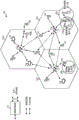
Fig. 1 is a block diagram conceptually illustrating an example of a telecommunications system.
Fig. 2 is a block diagram conceptually illustrating an example of a downlink frame structure in a telecommunication system.
Fig. 3 is a block diagram conceptually illustrating a design of a base station/eNB and a UE.
Fig. 4 is a block diagram illustrating another example communication system.
Fig. 5 is a block diagram of yet another example communication system.
Fig. 6 is a call flow diagram illustrating X2 communication interface initiation between (H) enbs.
Fig. 7 illustrates an exemplary methodology initiated for the X2 interface of a source node.
Fig. 8 illustrates an exemplary methodology initiated for the X2 interface of a target node.
Fig. 9 illustrates an embodiment of an apparatus for X2 interface initiation according to the methodology of fig. 7.
Fig. 10 illustrates an embodiment of an apparatus for X2 interface initiation according to the methodology of fig. 8.
Detailed Description
The detailed description set forth below in connection with the appended drawings is intended as a description of various configurations and is not intended to represent the only configurations in which the concepts described herein may be practiced. The detailed description includes specific details in order to provide a thorough understanding of the various concepts. It will be apparent, however, to one skilled in the art that these concepts may be practiced without these specific details. In some instances, well-known structures and components are shown in block diagram form in order to avoid obscuring such concepts.
The techniques described herein may be used for various wireless communication networks such as CDMA, TDMA, FDMA, OFDMA, SC-FDMA and other networks. The terms "network" and "system" are often used interchangeably. A CDMA network may implement radio technologies such as Universal Terrestrial Radio Access (UTRA), CDMA2000, and so on. UTRA includes wideband CDMA (wcdma) and other variants of CDMA. cdma2000 covers IS-2000, IS-95 and IS-856 standards. TDMA networks may implement radio technologies such as global system for mobile communications (GSM). An OFDMA network may implement radio technologies such as evolved UTRA (E-UTRA), Ultra Mobile Broadband (UMB), IEEE 802.11(Wi-Fi), IEEE 802.16(WiMAX), IEEE 802.20, Flash-OFDM, etc. UTRA and E-UTRA are part of the Universal Mobile Telecommunications System (UMTS). 3GPP Long Term Evolution (LTE) and LTE-advanced (LTE-A) are new UMTS releases that use E-UTRA. UTRA, E-UTRA, UMTS, LTE-A, and GSM are described in literature from an organization named "third Generation partnership project" (3 GPP). CDMA2000 and UMB are described in documents from an organization named "third generation partnership project 2" (3GPP 2). The techniques described herein may be used for the above-mentioned wireless networks and radio technologies as well as other wireless networks and radio technologies. For clarity, certain aspects of the techniques are described below for LTE, and LTE terminology is used in much of the description below.
Fig. 1 shows a wireless communication network 100, which may be an LTE network. Wireless network 100 may include several enbs 110 and other network entities. An eNB may be a station that communicates with UEs and may also be referred to as a base station, a node B, an access point, or other terminology. Each eNB110 a, 110b, 110c may provide communication coverage for a particular geographic area. In 3GPP, the term "cell" can refer to a coverage area of an eNB and/or an eNB subsystem serving the coverage area, depending on the context in which the term is used.
An eNB may provide communication coverage for a macro cell, a pico cell, a femto cell, and/or other types of cells. A macro cell may cover a relatively large geographic area (e.g., several kilometers in radius) and may allow unrestricted access by UEs with service subscriptions. Picocells may cover a relatively small geographic area and may allow unrestricted access by UEs with service subscriptions. A femtocell may cover a relatively small geographic area (e.g., a residence) and may be restrictively accessible by UEs associated with the femtocell (e.g., UEs in a Closed Subscriber Group (CSG), UEs of users in the residence, etc.). The eNB for a macro cell may be referred to as a macro eNB. An eNB for a picocell may be referred to as a pico eNB. An eNB for a femtocell may be referred to as a femto eNB or a home eNB (hnb). In the example shown in fig. 1, enbs 110a, 110b and 110c may be macro enbs for macro cells 102a, 102b and 102c, respectively. eNB110 x may be a pico eNB for pico cell 102 x. enbs 110y and 110z may be femto enbs for femto cells 102y and 102z, respectively. An eNB may support one or more (e.g., three) cells.
LTE utilizes Orthogonal Frequency Division Multiplexing (OFDM) on the downlink and single carrier frequency division multiplexing (SC-FDM) on the uplink. OFDM and SC-FDM partition the system bandwidth into multiple (K) orthogonal subcarriers, which are also commonly referred to as tones, bins, and so on. Each subcarrier may be modulated with data. In general, modulation symbols are sent in the frequency domain under OFDM and in the time domain under SC-FDM. The spacing between adjacent subcarriers may be fixed, and the total number of subcarriers (K) may depend on the system bandwidth. For example, K may be equal to 128, 256, 512, 1024 or 2048 for a system bandwidth of 1.25, 2.5, 5, 10 or 20 megahertz (MHz), respectively. The system bandwidth may also be divided into sub-bands. For example, a sub-band may cover 1.08MHz, and for a system bandwidth of 1.25, 2.5, 5, 10, or 20MHz, there may be 1, 2, 4, 8, or 16 sub-bands, respectively.
Fig. 2 shows a downlink frame structure used in LTE. The transmission timeline for the downlink may be partitioned into units of radio frames. Each radio frame (e.g., frame 202) may have a predetermined duration (e.g., 10 milliseconds (ms)) and may be divided into 10 subframes 204 with indices of 0 through 9. Each subframe (e.g., 'subframe 0' 206) may include two slots, e.g., 'slot 0' 208 and 'slot 1' 210. Each radio frame may thus comprise 20 time slots with indices 0 to 19. Each slot may include L symbol periods, e.g., 7 symbol periods 212 for a normal Cyclic Prefix (CP), as shown in fig. 2, or 6 symbol periods for an extended cyclic prefix. The normal CP and the extended CP may be referred to herein as different CP types. The 2L symbol periods in each subframe may be assigned indices 0 through 2L-1. The available time-frequency resources may be divided into resource blocks. Each resource block may cover N subcarriers (e.g., 12 subcarriers) in one slot.
In LTE, an eNB may transmit a Primary Synchronization Signal (PSS) and a Secondary Synchronization Signal (SSS) for each cell in the eNB. As shown in fig. 2, these primary and secondary synchronization signals may be sent in symbol periods 6 and 5, respectively, in each of subframes 0 and 5 of each radio frame with a normal cyclic prefix. The synchronization signal may be used by the UE for cell detection and acquisition. The eNB may send a Physical Broadcast Channel (PBCH) in symbol periods 0 through 3 in slot 1 of subframe 0. The PBCH may carry certain system information.
The eNB may transmit a Physical Control Format Indicator Channel (PCFICH) in only a portion of the first symbol period of each subframe, although depicted in fig. 2 as being transmitted in the entire first symbol period 214. The PCFICH may convey the number of symbol periods (M) used for the control channel, where M may be equal to 1, 2, or 3 and may vary from subframe to subframe. For small system bandwidths (e.g., having less than 10 resource blocks), M may also be equal to 4. In the example shown in fig. 2, M is 3. The eNB may transmit a Physical HARQ Indicator Channel (PHICH) and a Physical Downlink Control Channel (PDCCH) in the first M symbol periods of each subframe (M ═ 3 in fig. 2). The PHICH may carry information for supporting hybrid automatic repeat request (HARQ). The PDCCH may carry information on resource allocation to the UE and control information for a downlink channel. Although not shown in the first symbol period in fig. 2, it is understood that the PDCCH and PHICH are also included in the first symbol period. Similarly, both the PHICH and PDCCH are also in the second and third symbol periods, although not shown as such in fig. 2. The eNB may send a Physical Downlink Shared Channel (PDSCH) in the remaining symbol periods of each subframe. The PDSCH may carry data that is given to UEs scheduled for data transmission on the downlink. Various signals and channels in LTE are publicly available under the heading "Evolved Universal radio Access (E-UTRA); physical Channels and Modulation is described in 3GPP TS 36.211 of evolved Universal terrestrial radio Access (E-UTRA); Physical channel and Modulation.
The eNB may transmit the PSS, SSS, and PBCH in the center 1.08MHz of the system bandwidth used by the eNB. The eNB may transmit these channels across the entire system bandwidth in each symbol period in which the PCFICH and PHICH are transmitted. The eNB may send the PDCCH to the group of UEs in some portion of the system bandwidth. The eNB may transmit the PDSCH to a particular UE in a particular portion of the system bandwidth. The eNB may transmit the PSS, SSS, PBCH, PCFICH, and PHICH to all UEs in a broadcast manner, may transmit the PDCCH to a specific UE in a unicast manner, and may also transmit the PDSCH to a specific UE in a unicast manner.
The UE may be within coverage of multiple enbs. One of the enbs may be selected to serve the UE. The serving eNB may be selected based on various criteria such as received power, path loss, signal-to-noise ratio (SNR), and so on.
FIG. 3 shows a block diagram of a design of base station/eNB 110 and UE 120, which may be one of the base stations/eNBs and one of the UEs in FIG. 1. For the constrained association scenario, base station 110 may be macro eNB110 c in fig. 1, and UE 120 may be UE 120 y. The base station 110 may also be some other type of base station such as an access point including a femtocell, a picocell, or the like. Base station 110 may be equipped with antennas 334a through 334t and UE 120 may be equipped with antennas 352a through 352 r.
At base station 110, a transmit processor 320 may receive data from a data source 312 and control information from a controller/processor 340. The control information may be used for PBCH, PCFICH, PHICH, PDCCH, etc. Data may be used for PDSCH, etc. Processor 320 may process (e.g., encode and symbol map) the data and control information to obtain data symbols and control symbols, respectively. Processor 320 may also generate reference symbols (e.g., for PSS, SSS, and cell-specific reference signals). A Transmit (TX) multiple-input multiple-output (MIMO) processor 330 may perform spatial processing (e.g., precoding) on the data symbols, the control symbols, and/or the reference symbols, if applicable, and may provide output symbol streams to Modulators (MODs) 332a through 332 t. Each modulator 332 may process a respective output symbol stream (e.g., for OFDM, etc.) to obtain an output sample stream. Each modulator 332 may further process (e.g., convert to analog, amplify, filter, and upconvert) the output sample stream to obtain a downlink signal. Downlink signals from modulators 332a through 332t may be transmitted via antennas 334a through 334t, respectively.
At UE 120, antennas 352a through 352r may receive the downlink signals from base station 110 and may provide received signals to demodulators (DEMODs) 354a through 354r, respectively. Each demodulator 354 may condition (e.g., filter, amplify, downconvert, and digitize) a respective received signal to obtain input samples. Each demodulator 354 may further process the input samples (e.g., for OFDM, etc.) to obtain received symbols. A MIMO detector 356 may obtain received symbols from all demodulators 354a through 354r, perform MIMO detection on the received symbols if applicable, and provide detected symbols. A receive processor 358 may process (e.g., demodulate, deinterleave, and decode) the detected symbols, provide decoded data for UE 120 to a data sink 360, and provide decoded control information to a controller/processor 380.
On the uplink, at UE 120, a transmit processor 364 may receive and process data (e.g., for the PUSCH) from a data source 362 and control information (e.g., for the PUCCH) from a controller/processor 380. Processor 364 may also generate reference symbols for a reference signal. The symbols from the transmit processor 364 may be precoded by a TXMIMO processor 366 if applicable, further processed by the modulators 354a through 354r (e.g., for SC-FDM, etc.), and transmitted to the base station 110. At base station 110, the uplink signals from UE 120 may be received by antennas 334, processed by demodulators 332, detected by a MIMO detector 336 if applicable, and further processed by a receive processor 338 to obtain decoded data and control information sent by UE 120. Processor 338 may provide the decoded data to a data sink 339 and the decoded control information to controller/processor 340.
Controllers/ processors 340 and 380 may direct the operation at base station 110 and UE 120, respectively. Processor 340 and/or other processors and modules at base station 110 may perform or direct the implementation of various processes for the techniques described herein. Processor 380 and/or other processors and modules at UE 120 may also perform or direct the performance of the functional blocks illustrated in fig. 4 and 5, and/or other processes for the techniques described herein. Memories 342 and 382 may store data and program codes for base station 110 and UE 120, respectively. A scheduler 344 may schedule UEs for data transmission on the downlink and/or uplink.
In one configuration, the UE 120 for wireless communication includes: the apparatus generally includes means for detecting interference from an interfering base station during a connected mode of a UE, means for selecting a yielding resource of the interfering base station, means for obtaining an error rate of a physical downlink control channel on the yielding resource, and means for declaring a radio link failure that may be performed in response to the error rate exceeding a predetermined level. In one aspect, the aforementioned means may be the processor, controller/processor 380, memory 382, receive processor 358, MIMO detector 356, demodulator 354a, and antenna 352a configured to perform the functions recited by the aforementioned means. In another aspect, the aforementioned means may be a module or any device configured to perform the functions recited by the aforementioned means.
Fig. 4 is an illustration of a planned or semi-planned wireless communication environment 400, in accordance with various aspects. The communication environment 400 includes a plurality of access point base stations (including FAP410) each installed in a corresponding small scale network environment. Examples of small scale network environments may include user residences, businesses, indoor/outdoor facilities 430, and so forth. FAP410 may be configured to serve associated UEs 40 (e.g., included in a CSG associated with FAP410), or optionally alien or guest UEs 40 (e.g., UEs not configured for that CSG of FAP 410). Each FAP410 is further coupled to a Wide Area Network (WAN) (e.g., the internet 440) and a mobile operator core network 450 via a DSL router, a cable modem, a broadband over power line connection, a satellite internet connection, or the like.
To enable wireless service via the FAP410, the owner of the FAP410 subscribes to mobile services provided through the mobile operator core network 450. In addition, the UE 40 may be capable of utilizing the various techniques described herein to operate in a macro-cellular environment and/or in a residential small-scale network environment. Thus, at least in some disclosed aspects, the FAP410 may be backward compatible with any suitable existing UE 40. In addition, in addition to the macro cell mobile network 455, the UE 40 is served by a predetermined number of FAPs 410, particularly FAPs 410 residing within the respective user residence(s), business(s), or indoor/outdoor facilities 430, and may not be in a soft handover state with the macro cell mobile network 455 of the mobile operator core network 450. It should be appreciated that although aspects described herein employ 3GPP terminology, it should be understood that these aspects may also be applied to a variety of technologies, including 3GPP technologies (release 99[ Rel99], release 5, release 6, release 7), 3GPP2 technologies (1xRTT, 1xEV-DO release 0, revision a, revision B), and other known and related technologies.
In at least one embodiment, enbs are typically interconnected with other enbs via an interface, referred to as an "X2" interface, which may be a logical interface (e.g., a point-to-point link) that enables at least two respective enbs to be directly connected to each other (e.g., in a peer-to-peer manner) to facilitate communication with each other. In this regard, an X2 interface may be established between one eNB and some of its neighbor enbs to exchange signaling information, as well as other types of information or data. In an example, initialization of the X2 interface may begin at a first eNB with identification of a suitable neighbor eNB, followed by establishment of a Transport Network Layer (TNL). In some implementations, the identification of neighbors may be made through configuration or through an automatic neighbor relation function. In a similar manner, a given HeNB may also establish connections between other henbs via the X2 interface to enable direct communication between each other. Thus, the X2 interface may thus connect neighbor enbs to each other or neighbor henbs to each other in a peer-to-peer manner to assist in coordinating radio resources, load management, and other functions, etc., in, for example, handover. In one example, an eNB may be connected to an X2 gateway and a HeNB may also be connected to the same X2 gateway. In some circumstances, it may be advantageous to enable an X2 interface to connect an eNB with a HeNB and/or vice versa in accordance with embodiments described herein.
Fig. 5 is a block diagram of yet another example communication system 500, depicting an X2 gateway (X2-GW) reference architecture. The X2 interface may be used for direct communication between the eNB and the HeNB. Fig. 5 shows an X2-GW505 coupled to enbs 506, 507, and 508 and henbs 530, 535 via respective X2 interfaces. As illustrated in fig. 5, the aforementioned enbs/henbs may connect to other enbs/henbs via "direct" X2 interfaces 511, 512, 515, 518, and 519, or via "indirect" X2 interfaces 510, 513, 514, 516, 517, and 520 by X2-GW505 acting as a proxy server. With the addition of the X2-GW505, the X2 interface may be modified to cause the X2-GW505 to function as described further below. The X2-GW505 may act as a full proxy, with henbs and enbs connecting to the X2-GW505 using existing X2 setup and reset procedures. The HeNB and eNB route the X2 message to the X2-GW505 (e.g., based on eNB ID, TAI, e-CGI, CSG ID, etc.) so that there may be no need to exchange eNB configurations between these enbs and the cells behind the X2-GW505 may be hidden from the source eNB. The X2-GW505 may also act as a routing agent, where eNB-to-HeNB or HeNB-to-HeNB X2 messages may be routed at the X2-GW505 based on (H) eNBID or cell ID (e.g., target and source (H) eNB ID may need to be added to the X2 message if needed to enable simple routing by the X2-GW 505). Note that here X2-GW505 refers to either the X2 full proxy or the X2 routing proxy as defined. It may be noted that an error message may need to be defined for the case where X2-GW505 does not support the eNB ID/cell ID of the received message.
An X2-GW505 may be present in 3GPP to facilitate X2 connectivity between henbs and enbs. The X2-GW505 may act as a proxy between peer nodes such that it may facilitate X2 to establish and route other X2 application protocol (X2AP) connections.
One issue may relate to how to determine whether to establish a direct or indirect X2 interface for communication between neighboring (H) enbs. When an (H) eNB discovers (e.g., discovers for the first time) another neighboring (H) eNB, the (H) eNB may learn a Transport Network Layer (TNL) (e.g., IP) address of the neighboring (H) eNB through a self-organizing network (SON) configuration transport procedure by the MME. In an embodiment, an (H) eNB may initiate a TNL address discovery procedure via a configuration transfer procedure, wherein the (H) eNB sends a configuration transfer message to an MME, which then forwards the message to the neighbor (H) eNB. The configuration transfer message may include, among other types of data, a request for a TNL or IP address, a global cell identifier of the neighbor (H) eNB, and/or a transport address of the (H) eNB, and after receiving the configuration transfer message, the neighbor (H) eNB sends back its TNL or IP address. For the X2-GW505, it may be reasonable to extend the procedure to also report the X2-GW505TNL address. The term source node or simply "source" may be used for a node that initiates a SON configuration transmission procedure, and the term target node or simply "target" may be used for a node that responds to the SON configuration transmission procedure.
In the current design, the HeNB may be connected to a single X2-GW505 and may be configured with the TNL address of that X2-GW 505. However, there may not be such a configuration for a macro eNB that may be connected to one or more X2-GWs 505.
To address the issue of determining whether to use the X2-GW505 (e.g., in an indirect X2 interface), it is proposed that the target (H) eNB may include the X2-GW505TNL address as part of the SON configuration transport procedure if the target can use or support an X2 connection with the source (H) eNB through the X2-GW 505.
The target node may not include the address if the target node may not use the X2-GW505 or preferably uses a direct X2 interface, e.g., based on operation, administration, maintenance (OAM) configuration and/or source identity (e.g., Physical Cell Identifier (PCI), enhanced cell global identifier (eCGI), Closed Subscriber Group (CSG) ID/membership, etc.).
If the target node is a macro eNB, the target may not be able to signal a particular X2-GW address, as there may be multiple X2-GWs to which the target may connect. If the target eNB can determine the X2-GW TNL address of the source HeNB based on the configuration, it may include the X2-GW TNL address in the SON configuration transmission to indicate that it may connect to the source via the X2-GW. However, if the X2-GW TNL address of the source HeNB is not available to the target, the target may still need to signal to the source HeNB that the eNB can use the connection via the X2-GW. To address this issue, a special value may be included in the X2-GW TNL address field in the SON configuration transport procedure. The special value may be chosen not to correspond to the actual TNL address or the eNB may include its own TNL address. This may allow the source HeNB to determine that the target eNB can use the X2-GW connection.
The current SON transport configuration message may include the target TNL address as a mandatory field. If the target (H) eNB prefers to use only indirect connections, it may also put a special value into the target TNL address, while including the X2-GW TNL address (or the specific value in case of macro eNB), where the special value indicates that the direct connection is not available.
It may be noted that when the target (H) eNB is connected to the X2-GW or when the target (H) eNB is aware that the source (H) eNB is connected to the X2-GW, the target (H) eNB may include the TNL address of the X2-GW in the SON configuration transfer message to indicate the availability of the X2 connection via the X2-GW. In another example, the target (H) eNB may include a special value for the X2-GWTNL address field in the SON configuration transfer message to indicate availability to use the X2-GW, where the special value may be a specific numerical value that does not correspond to a TNL address, or where the special value may be an actual TNL address of the target (H) eNB. In another example, the target (H) eNB may include a special value in the target (H) eNB TNL address to indicate that a direct X2 connection is not available for the source eNB. Determining whether to use an X2-GW for an X2 connection (for indirect interfaces) or not for an X2 connection (for direct interfaces) may be configured by OAM based on source (H) eNB identity information, including information such as: PCI, or eCGI, CSGID/membership, etc.
It may be noted that the source (H) eNB may determine whether to use an X2 connection via an X2-GW by combining the identity information of the target (H) eNB (including PCI, eCGI, CSG ID/membership) with an indication of availability of an X2-GW based connection at the target received from the target in the SON configuration transfer message. The source (H) eNB may make this selection when the target supports both direct and indirect X2 connections, even if the target node indicates a preference for one X2 interface. For example, even if the target node sends an X2-GW TNL address indicating a preference for an indirect X2 interface, the source node may determine to use the direct interface, overriding or ignoring the target node's preference. In this case, the source node may decide to use the direct X2 interface or the indirect X2 interface, even though (or alternatively, regardless of whether) the target node supports the indirect X2 interface. The source (H) eNB may send an X2 setup request to the target (H) eNB or to the X2-GW based on the determination.
Fig. 6 is a call flow diagram illustrating X2 communication interface initiation between (H) enbs. The example communication system in fig. 6 may include one or more (H) enbs 110d-e, X2-GW 610, and core network 620. The X2 interface initiation procedure may include one of a direct X2 interface between (H) enbs or an indirect X2 interface between (H) enbs.
In the example of fig. 6, the process may begin with the discovery of a neighboring node by (H) eNB110d, such as (H) eNB110e, at step 650. After discovering the neighboring node (H) eNB110e, (H) eNB110d may determine the address of the neighboring node. For example, (H) eNB110d may initiate a TNL address discovery procedure to determine the TNL address of (H) eNB110 e. In an embodiment, as part of initiating the TNL address discovery procedure, eNB110d may send the TNL address request in a message to eNB110 e. In this case, the node (H) eNB110d that sent the TNL address request may be referred to as the source node and the destination node (H) eNB110e may be referred to as the target node. In steps 652A-B, (H) eNB110d may determine (H) the TNL address of eNB110 e. In an embodiment, the TNL address discovery procedure may be performed by a message to the target node (H) eNB110d issued via the core network 620. For example, the message may be a SON configuration transfer message. The target node (H) eNB110e may determine whether it desires to use a direct X2 connection or an indirect X2 connection or interface via an X2-GW acting as a proxy. The determination of whether to use the direct or indirect interface may be based on OAM configuration, source node identity and target node identity, or whether the target node (H) eNB110e supports the direct and/or indirect interface.
In the case where (H) eNB110e determines to use an indirect interface via the X2-GW, (H) eNB110e may send the TNL address of the X2-GW in a SON configuration transfer message. If the target node (H) eNB110e is a macro node, then the (H) eNB110e may be connected to more than one X2-GW. For this case, in one example, (H) eNB110e may include a special value (e.g., may be a predetermined value known to the source node) to indicate that the target node is a macro node that supports an interface connected via X2-GW. For this case, in another example, (H) eNB110e may include its own TNL address in the field for the X2-GW TNL address.
In the case where (H) eNB110e determines to use the direct interface, (H) eNB110d may not send the X2-GW TNL address by not including any information in this field, or it may send a special value (e.g., may be a predetermined value known to the source node) to indicate that (H) eNB110e does not support the indirect interface or desires to use the direct interface.
At step 654, (H) eNB110d may determine whether to use the direct or indirect interface. For example, the determination may be based on a TNL address received in the SON configuration transfer message. In the case where (H) eNB110d determines to use the direct interface, (H) eNB110d may initiate an X2 interface with (H) eNB110e at step 656A. In the case where (H) eNB110e determines to use the indirect interface, (H) eNB110d may initiate an X2 interface with (H) eNB110e via X2-GW 610 in step 656B.
In accordance with one or more aspects of various embodiments described herein, with reference to fig. 7, illustrated is a methodology 700 that is operable by a network entity (such as, for example, a femtocell, a macrocell, a picocell, or the like). In particular, the method 700 describes a procedure for initiating an X2 interface at a source node. The method 700 can involve discovering a neighbor node at an access point, at 702. Method 700 may involve, at 704, receiving, via a network message, an address indication associated with the neighboring node for configuring a communication interface. The method 700 may involve determining whether to initiate one of a direct communication interface or an indirect communication interface for communicating with the neighbor node based on the address indication in the received network message, at 706.
Referring to fig. 8, illustrated is a methodology 800 that is operable by a network entity (such as, for example, a femtocell, a macrocell, a picocell, or the like). In particular, the method 800 describes procedures for initiating an X2 interface at a source node. Method 800 may involve, at 802, receiving a request for an address from a neighboring node via a network message, the request relating to initiating an interface between the neighboring node and an access point. The method 800 may involve, at 804, determining an address indication of the access point for transmission to the neighboring node via a network message based on the determination of whether to use the direct communication interface or the indirect communication interface. The method 800 may involve, at 806, sending the address indication to the neighboring node via a network message for initiating the communication interface.
Fig. 9 illustrates an embodiment of an apparatus for initiating an X2 interface in accordance with the methodology of fig. 7. Referring to fig. 9, an example apparatus 900 is provided that may be configured as a network entity (e.g., a femtocell, a macrocell, a picocell, or the like) in a wireless network, or as a processor or similar device/component for use within the network entity. Apparatus 900 may include functional blocks that can represent functions implemented by a processor, software, or combination thereof (e.g., firmware). For example, apparatus 900 may include an electrical component or module 902 for discovering a neighbor node at an access point. Apparatus 900 may include an electrical component or module 904 for receiving, via a network message, an address indication associated with the neighboring node for configuring a communication interface. Apparatus 900 may include an electrical component or module 906 for determining whether to initiate one of a direct communication interface or an indirect communication interface for communicating with the neighboring node based on the address indication in the received network message.
In related aspects, in a case where the apparatus 900 is configured as a network entity (e.g., a femtocell, a macrocell, a picocell, or the like) rather than a processor, the apparatus 900 may optionally include a processor component 910 having at least one processor. In such cases, the processor 910 may be in operative communication with the components 902 and 906 via a bus 952 or similar communication coupling. Processor 910 can effectuate the initiation and scheduling of processes or functions performed by electrical components 902-906.
In a further related aspect, apparatus 900 may include a radio transceiver component 914. A standalone receiver and/or a standalone transmitter may be used in place of or in conjunction with the transceiver 914. When the apparatus 900 is a network entity, the apparatus 900 may further comprise a network interface (not shown) for connecting to one or more core network entities. The apparatus 900 may optionally include a component for storing information, such as, for example, a memory device/component 916. A computer-readable medium or a memory component 956 may be operatively coupled to the other components of the device 900 via a bus 952 or the like. The memory component 916 may be adapted to store computer readable instructions and data for carrying out the processes and acts of the components 902 and 906 and their subcomponents, or the processor 910, or the methods disclosed herein. The memory component 916 can retain instructions for performing the functions associated with components 902-906. While shown as being external to memory 916, it is to be understood that component 902 and 906 can exist within memory 916. It should also be noted that the components in fig. 9 may include a processor, electronics, hardware devices, electronic sub-components, logic circuits, memory, software code, firmware code, etc., or any combination thereof.
FIG. 10 illustrates an embodiment of an apparatus for initiating an X2 interface in accordance with the methodology of FIG. 8. Referring to fig. 10, an example apparatus 1000 is provided that may be configured as a network entity (e.g., a femtocell, a macrocell, a picocell, or the like) in a wireless network, or as a processor or similar device/component for use within the network entity. Apparatus 1000 may include functional blocks that can represent functions implemented by a processor, software, or combination thereof (e.g., firmware). For example, apparatus 1000 may include an electrical component or module 1002 for receiving a request for an address from a neighboring node via a network message, the request relating to initiating an interface between the neighboring node and an access point. Apparatus 1000 may include an electrical component or module for determining an address indication of the access point for transmission to the neighboring node via a network message based on the determination of whether to use the direct communication interface or the indirect communication interface 1004. Apparatus 1000 may include an electrical component or module for sending the address indication to the neighboring node via a network message for initiating the communication interface 1006.
In related aspects, in a case where apparatus 1000 is configured as a network entity (e.g., a femtocell, a macrocell, a picocell, or the like) rather than a processor, apparatus 1000 may optionally include a processor component 1010 having at least one processor. In such cases, the processor 1010 may be in operative communication with the component 1002-1006 via a bus 1052 or similar communication coupling. The processor 1010 can effectuate the initiation and scheduling of processes or functions performed by the electrical components 1002-1006.
In a further related aspect, apparatus 1000 may include a radio transceiver component 1014. A separate receiver and/or a separate transmitter may be used in place of or in combination with the transceiver 1014. When the apparatus 1000 is a network entity, the apparatus 1000 may further comprise a network interface (not shown) for connecting to one or more core network entities. The apparatus 1000 may optionally include a component for storing information, such as, for example, a memory device/component 1016. A computer-readable medium or memory component 1056 may be operatively coupled to the other components of the device 1000 via the bus 1052 or the like. The memory component 1016 may be adapted to store computer readable instructions and data for carrying out the processes and acts of the components 1002-1006 and subcomponents thereof, or the processor 1010, or methods disclosed herein. The memory component 1016 can retain instructions for performing the functions associated with the components 1002-1006. While shown as being external to memory 1016, it is to be understood that component 1002-1006 can exist within memory 1016. It should also be noted that the components in fig. 10 may include processors, electronics devices, hardware devices, electronic sub-components, logic circuits, memories, software codes, firmware codes, etc., or any combination thereof.
Those of skill in the art would understand that information and signals may be represented using any of a variety of different technologies and techniques. For example, data, instructions, commands, information, signals, bits (bits), symbols, and chips that may be referenced throughout the above description may be represented by voltages, currents, electromagnetic waves, magnetic fields or particles, optical fields or particles, or any combination thereof.
Those of skill would further appreciate that the various illustrative logical blocks, modules, circuits, and algorithm steps described in connection with the disclosure herein may be implemented as electronic hardware, computer software, or combinations of both. To clearly illustrate this interchangeability of hardware and software, various illustrative components, blocks, modules, circuits, and steps have been described above generally in terms of their functionality. Whether such functionality is implemented as hardware or software depends upon the particular application and design constraints imposed on the overall system. Skilled artisans may implement the described functionality in varying ways for each particular application, but such implementation decisions should not be interpreted as causing a departure from the scope of the present disclosure.
The various illustrative logical blocks, modules, and circuits described in connection with the disclosure herein may be implemented or performed with a general purpose processor, a Digital Signal Processor (DSP), an Application Specific Integrated Circuit (ASIC), a Field Programmable Gate Array (FPGA) or other programmable logic device, discrete gate or transistor logic, discrete hardware components, or any combination thereof designed to perform the functions described herein. A general purpose processor may be a microprocessor, but in the alternative, the processor may be any conventional processor, controller, microcontroller, or state machine. A processor may also be implemented as a combination of computing devices, e.g., a combination of a DSP and a microprocessor, a plurality of microprocessors, one or more microprocessors in conjunction with a DSP core, or any other such configuration.
The steps of a method or algorithm described in connection with the disclosure herein may be embodied directly in hardware, in a software module executed by a processor, or in a combination of the two. A software module may reside in RAM memory, flash memory, ROM memory, EPROM memory, EEPROM memory, registers, hard disk, a removable disk, a CD-ROM, or any other form of storage medium known in the art. An exemplary storage medium is coupled to the processor such the processor can read information from, and write information to, the storage medium. In the alternative, the storage medium may be integral to the processor. The processor and the storage medium may reside in an ASIC. The ASIC may reside in a user terminal. In the alternative, the processor and the storage medium may reside as discrete components in a user terminal.
In one or more exemplary designs, the functions described may be implemented in hardware, software, firmware, or any combination thereof. If implemented in software, the functions may be stored on or transmitted over as one or more instructions or code on a computer-readable medium. Computer-readable media includes both computer storage media and communication media including any medium that facilitates transfer of a computer program from one place to another. A storage media may be any available media that can be accessed by a general purpose or special purpose computer. By way of example, and not limitation, such computer-readable media can comprise RAM, ROM, EEPROM, CD-ROM or other optical disk storage, magnetic disk storage or other magnetic storage devices, or any other medium which can be used to carry or store desired program code means in the form of instructions or data structures and which can be accessed by a general-purpose or special-purpose computer, or a general-purpose or special-purpose processor. Any connection is properly termed a computer-readable medium. For example, if the software is transmitted from a web site, server, or other remote source using a coaxial cable, fiber optic cable, twisted pair, Digital Subscriber Line (DSL), or wireless technologies such as infrared, radio, and microwave, then the coaxial cable, fiber optic cable, twisted pair, DSL, or wireless technologies such as infrared, radio, and microwave are included in the definition of medium. Disk (disk) and disc (disc), as used herein, includes Compact Disc (CD), laser disc, optical disc, Digital Versatile Disc (DVD), floppy disk and blu-ray disc where disks (disks) usually reproduce data magnetically, while discs (discs) reproduce data optically with lasers. Combinations of the above should also be included within the scope of computer-readable media.
The previous description of the disclosure is provided to enable any person skilled in the art to make or use the disclosure. Various modifications to the disclosure will be readily apparent to those skilled in the art, and the generic principles defined herein may be applied to other variations without departing from the spirit or scope of the disclosure. Thus, the disclosure is not intended to be limited to the examples and designs described herein but is to be accorded the widest scope consistent with the principles and novel features disclosed herein.
Claims (30)
1. A method for initiating a communication interface in a wireless communication system, the method comprising:
discovering a neighbor node at an access point;
receiving, based on discovering the neighbor node, a network message including an address indication associated with the neighbor node for configuring the communication interface, wherein the address indication includes both a field for an address of the neighbor node and a field for an address of a gateway acting as a proxy; and
determining, based on the address indication and based on at least one of: support for the direct communication interface, support for the indirect communication interface, operation, administration, maintenance (OAM) configuration, an identity of the neighbor node, the identity of the neighbor node comprising a Physical Cell Identifier (PCI), or a Closed Subscriber Group (CSG) identity.
2. The method of claim 1, wherein the direct communication interface comprises an X2 interface and the indirect communication interface comprises an X2 interface via an X2 gateway (X2-GW) that acts as a proxy.
3. The method of claim 1, wherein determining whether to initiate one of the direct communication interface or the indirect communication interface comprises:
determining to initiate the direct communication interface when the address indication indicates that the neighbor node does not support the indirect communication interface.
4. The method of claim 1, wherein determining whether to initiate one of the direct communication interface or the indirect communication interface is based on a configuration of the access point.
5. The method of claim 1, wherein determining whether to initiate one of the direct communication interface or the indirect communication interface is based on an enhanced cell global identifier (eCGI).
6. The method of claim 1, further comprising:
initiate the direct communication interface or the indirect communication interface based on determining whether to initiate one of the direct communication interface or the indirect communication interface.
7. The method of claim 1, further comprising:
after discovering the neighbor node at the access point, initiating Transport Network Layer (TNL) address discovery by sending a TNL address request to the neighbor node, wherein receiving the network message is based on initiating the TNL address discovery.
8. The method of claim 1, wherein the network message comprises a Self Organizing Network (SON) configuration transfer message including the address indication.
9. An apparatus for initiating a communication interface in a wireless communication system, the apparatus comprising:
means for discovering a neighbor node at the apparatus;
means for receiving, based on discovering the neighbor node, a network message comprising an address indication associated with the neighbor node for configuring the communication interface, wherein the address indication comprises both a field for an address of the neighbor node and a field for an address of a gateway acting as a proxy; and
means for determining, based on the address indication and based on at least one of: support for the direct communication interface, support for the indirect communication interface, operation, administration, maintenance (OAM) configuration, an identity of the neighbor node, the identity of the neighbor node comprising a Physical Cell Identifier (PCI), or a Closed Subscriber Group (CSG) identity.
10. The apparatus of claim 9, wherein the direct communication interface comprises an X2 interface and the indirect communication interface comprises an X2 interface via an X2 gateway (X2-GW) that acts as a proxy.
11. The apparatus of claim 9, wherein means for determining whether to initiate one of the direct communication interface or the indirect communication interface comprises:
means for determining to initiate the direct communication interface when the address indication indicates that the indirect communication interface is not supported by the neighboring node.
12. The apparatus of claim 9, wherein means for determining whether to initiate one of the direct communication interface or the indirect communication interface comprises:
means for determining whether to initiate one of the direct communication interface or the indirect communication interface based on whether the address indication includes an address or a special value associated with an X2 gateway (X2-GW) of the neighboring node.
13. The apparatus of claim 9, wherein means for determining whether to initiate one of the direct communication interface or the indirect communication interface comprises:
means for determining whether to initiate one of the direct communication interface or the indirect communication interface based on an enhanced cell global identifier (eCGI).
14. The apparatus of claim 9, wherein determining is further based on the address indication from a target, the apparatus further comprising:
means for initiating the direct communication interface or the indirect communication interface based on determining whether to initiate one of the direct communication interface or the indirect communication interface.
15. The apparatus of claim 9, further comprising:
means for initiating Transport Network Layer (TNL) address discovery after discovering the neighbor node at the apparatus by sending a TNL address request to the neighbor node, wherein the network message is received based on initiating the TNL address discovery.
16. The apparatus of claim 9, wherein the network message comprises a Self Organizing Network (SON) configuration transmission message including the address indication.
17. An apparatus for initiating a communication interface in a wireless communication system, the apparatus comprising:
at least one processor configured to discover a neighbor node at the apparatus;
at least one transceiver configured to receive, based on discovering the neighbor node, a network message comprising an address indication associated with the neighbor node for configuring the communication interface, wherein the address indication comprises both a field for an address of the neighbor node and a field for an address of a gateway serving as a proxy;
wherein the at least one processor is further configured to:
determining, based on the address indication and based on at least one of: support for the direct communication interface, support for the indirect communication interface, operation, administration, maintenance (OAM) configuration, an identity of the neighbor node, the identity of the neighbor node comprising a Physical Cell Identifier (PCI), or a Closed Subscriber Group (CSG) identity; and
a memory coupled to the at least one processor.
18. The apparatus of claim 17, wherein the direct communication interface comprises an X2 interface and the indirect communication interface comprises an X2 interface via an X2 gateway (X2-GW) that acts as a proxy.
19. The apparatus of claim 17, wherein the at least one processor, in determining whether to initiate one of the direct communication interface or the indirect communication interface, is configured to:
determining to initiate the direct communication interface when the address indication indicates that the neighbor node does not support the indirect communication interface.
20. The apparatus of claim 17, wherein the at least one processor, in determining whether to initiate one of the direct communication interface or the indirect communication interface, is configured to:
determining whether to initiate one of the direct communication interface or the indirect communication interface based on whether the address indication includes an address or a special value associated with an X2 gateway (X2-GW) of the neighboring node.
21. The apparatus of claim 17, wherein the at least one processor, in determining whether to initiate one of the direct communication interface or the indirect communication interface, is configured to:
determining whether to initiate one of the direct communication interface or the indirect communication interface based on an enhanced cell global identifier (eCGI).
22. The apparatus of claim 17, wherein determining is further based on the address indication from a target, wherein the at least one processor is further configured to:
initiate the direct communication interface or the indirect communication interface based on determining whether to initiate one of the direct communication interface or the indirect communication interface.
23. The apparatus of claim 17, in which the at least one processor is further configured:
after discovering the neighbor node at the apparatus, initiating Transport Network Layer (TNL) address discovery by sending a TNL address request to the neighbor node, and wherein the network message is received based on initiating the TNL address discovery.
24. The apparatus of claim 17, wherein the network message comprises a Self Organizing Network (SON) configuration transfer message including the address indication.
25. A non-transitory computer-readable medium storing instructions that, when executed by at least one computer, cause the at least one computer to:
discovering a neighbor node at an access point;
receiving, based on discovering the neighbor node, a network message including an address indication associated with the neighbor node for configuring a communication interface, wherein the address indication includes both a field for an address of the neighbor node and a field for an address of a gateway acting as a proxy; and
determining, based on the address indication and based on at least one of: support for the direct communication interface, support for the indirect communication interface, operation, administration, maintenance (OAM) configuration, an identity of the neighbor node, the identity of the neighbor node comprising a Physical Cell Identifier (PCI), or a Closed Subscriber Group (CSG) identity.
26. The non-transitory computer-readable medium of claim 25, wherein the direct communication interface comprises an X2 interface and the indirect communication interface comprises an X2 interface via an X2 gateway (X2-GW) that acts as a proxy.
27. The non-transitory computer-readable medium of claim 25, wherein determining whether to initiate one of the direct communication interface or the indirect communication interface comprises:
determining to initiate the direct communication interface when the address indication indicates that the neighbor node does not support the indirect communication interface.
28. The non-transitory computer-readable medium of claim 25, wherein determining whether to initiate one of the direct communication interface or the indirect communication interface comprises:
determining whether to initiate one of the direct communication interface or the indirect communication interface based on a configuration of the access point.
29. The non-transitory computer-readable medium of claim 25, wherein determining whether to initiate one of the direct communication interface or the indirect communication interface comprises:
determining whether to initiate one of the direct communication interface or the indirect communication interface based on an enhanced cell global identifier (eCGI).
30. The non-transitory computer-readable medium of claim 25, further comprising:
the instructions, when executed by the at least one computer, cause the at least one computer to:
initiating Transport Network Layer (TNL) address discovery by sending a TNL address request to the neighbor node after discovering the neighbor node at the access point,
wherein the network message is received based on initiating the TNL address discovery, and
wherein the network message comprises a self-organizing network (SON) configuration transfer message including the address indication.
Applications Claiming Priority (5)
| Application Number | Priority Date | Filing Date | Title |
|---|---|---|---|
| US201361899022P | 2013-11-01 | 2013-11-01 | |
| US61/899,022 | 2013-11-01 | ||
| US14/528,989 US9668198B2 (en) | 2013-11-01 | 2014-10-30 | Method and apparatus for determining to use X2 gateway for X2 interface |
| US14/528,989 | 2014-10-30 | ||
| PCT/US2014/063525 WO2015066527A1 (en) | 2013-11-01 | 2014-10-31 | Method and apparatus for determining to use x2 gateway for x2 interface |
Publications (2)
| Publication Number | Publication Date |
|---|---|
| CN105723768A CN105723768A (en) | 2016-06-29 |
| CN105723768B true CN105723768B (en) | 2020-04-24 |
Family
ID=51901014
Family Applications (1)
| Application Number | Title | Priority Date | Filing Date |
|---|---|---|---|
| CN201480059742.XA Active CN105723768B (en) | 2013-11-01 | 2014-10-31 | Method and apparatus for determining use of an X2 gateway for an X2 interface |
Country Status (8)
| Country | Link |
|---|---|
| US (1) | US9668198B2 (en) |
| EP (1) | EP3063977B1 (en) |
| JP (1) | JP6388937B2 (en) |
| KR (1) | KR101789461B1 (en) |
| CN (1) | CN105723768B (en) |
| BR (1) | BR112016009815B1 (en) |
| CA (1) | CA2927796C (en) |
| WO (1) | WO2015066527A1 (en) |
Families Citing this family (11)
| Publication number | Priority date | Publication date | Assignee | Title |
|---|---|---|---|---|
| US10057838B2 (en) * | 2013-04-26 | 2018-08-21 | Qualcomm Incorporated | X2 setup and routing at an X2-gateway |
| DE102017109383A1 (en) | 2016-05-02 | 2017-11-02 | Patentpool Innovations Management Gmbh | Method for data communication using random network addresses and corresponding device |
| US9961527B2 (en) | 2016-06-30 | 2018-05-01 | Verizon Patent And Licensing Inc. | Access control and scheduling mechanism for MTC devices |
| EP3504927A1 (en) * | 2016-08-25 | 2019-07-03 | Telefonaktiebolaget LM Ericsson (PUBL) | Connection establishment for node connected to multiple ip networks |
| WO2018127470A1 (en) * | 2017-01-06 | 2018-07-12 | Koninklijke Philips N.V. | Using time-of-flight to detect and correct misalignment in pet/ct imaging |
| US10531275B2 (en) * | 2016-12-12 | 2020-01-07 | Commscope Technologies Llc | Cluster neighbor discovery in centralized radio access network using transport network layer (TNL) address discovery |
| WO2018174792A1 (en) * | 2017-03-24 | 2018-09-27 | Telefonaktiebolaget Lm Ericsson (Publ) | A first radio network node (rnn), a second rnn and methods therein for establishing a communications interface between the first rnn and the second rnn |
| US11122412B2 (en) * | 2017-05-09 | 2021-09-14 | Intel Corporation | Device discovery |
| WO2019015900A1 (en) | 2017-07-18 | 2019-01-24 | British Telecommunications Public Limited Company | Cellular telecommunications network |
| DE102017125649A1 (en) | 2017-11-02 | 2019-06-19 | Prisma Analytics Gmbh | Method for data communication using random network addresses and a corresponding device |
| US11606842B2 (en) * | 2020-11-03 | 2023-03-14 | Celona, Inc. | Method and apparatus for MOCN GW and X2 GW realizations for enterprise deployments |
Family Cites Families (12)
| Publication number | Priority date | Publication date | Assignee | Title |
|---|---|---|---|---|
| NZ601064A (en) * | 2010-01-29 | 2014-08-29 | Elster Solutions Llc | Clearing redundant data in wireless mesh network |
| EP2398277B1 (en) * | 2010-06-16 | 2012-12-26 | Alcatel Lucent | Self-configuration of donor/relay eNode B interface |
| WO2012148217A2 (en) | 2011-04-28 | 2012-11-01 | Lg Electronics Inc. | Method and apparatus for initiating x2 interface setup in wireless communication system |
| CN102892165A (en) * | 2011-07-22 | 2013-01-23 | 中兴通讯股份有限公司 | Switching method and system for home evolved node base station |
| KR101430242B1 (en) * | 2011-08-01 | 2014-08-18 | 주식회사 케이티 | METHOD FOR SETTING X2 INTERFACE BETWEEN HeNBs AND HeMS |
| KR101840699B1 (en) * | 2011-12-15 | 2018-03-23 | 한국전자통신연구원 | Method of managing mobility using coordinated multiple moint communication |
| CN102595535A (en) * | 2012-01-18 | 2012-07-18 | 中兴通讯股份有限公司 | Information processing method, access network elements, core network elements, family base station and gateway |
| CN103220815B (en) * | 2012-01-18 | 2019-02-15 | 中兴通讯股份有限公司 | A kind of inter-base station interface connection method for building up and device |
| CN111225427B (en) | 2012-09-28 | 2022-06-10 | 北京三星通信技术研究有限公司 | Method for establishing X2 through gateway |
| DE112013002921B4 (en) | 2012-11-02 | 2024-02-08 | Lg Electronics Inc. | Method and device for transmitting an indication in a wireless communication system |
| US9603065B2 (en) * | 2013-04-03 | 2017-03-21 | Google Technology Holdings LLC | Methods and devices for cell discovery |
| GB2514806A (en) | 2013-06-04 | 2014-12-10 | Nec Corp | Communications system |
-
2014
- 2014-10-30 US US14/528,989 patent/US9668198B2/en active Active
- 2014-10-31 WO PCT/US2014/063525 patent/WO2015066527A1/en active Application Filing
- 2014-10-31 BR BR112016009815-3A patent/BR112016009815B1/en active IP Right Grant
- 2014-10-31 CA CA2927796A patent/CA2927796C/en active Active
- 2014-10-31 KR KR1020167013244A patent/KR101789461B1/en active IP Right Grant
- 2014-10-31 CN CN201480059742.XA patent/CN105723768B/en active Active
- 2014-10-31 JP JP2016526315A patent/JP6388937B2/en active Active
- 2014-10-31 EP EP14799301.8A patent/EP3063977B1/en active Active
Also Published As
| Publication number | Publication date |
|---|---|
| BR112016009815A2 (en) | 2017-08-01 |
| US20150124702A1 (en) | 2015-05-07 |
| JP2016535493A (en) | 2016-11-10 |
| CA2927796A1 (en) | 2015-05-07 |
| KR20160079001A (en) | 2016-07-05 |
| CN105723768A (en) | 2016-06-29 |
| BR112016009815B1 (en) | 2023-02-14 |
| WO2015066527A1 (en) | 2015-05-07 |
| CA2927796C (en) | 2018-09-11 |
| EP3063977B1 (en) | 2018-11-14 |
| EP3063977A1 (en) | 2016-09-07 |
| JP6388937B2 (en) | 2018-09-12 |
| KR101789461B1 (en) | 2017-10-23 |
| US9668198B2 (en) | 2017-05-30 |
Similar Documents
| Publication | Publication Date | Title |
|---|---|---|
| CN105723768B (en) | Method and apparatus for determining use of an X2 gateway for an X2 interface | |
| US9392627B2 (en) | Method and apparatus for physical cell identifier collision detection and neighboring cell list construction | |
| US9521561B2 (en) | UE-assisted network optimization methods | |
| KR101945952B1 (en) | X2 setup and routing at an x2-gateway | |
| US20130225183A1 (en) | Methods and apparatus for turning off macro carriers to deploy femtocells | |
| EP2965575A1 (en) | Uplink interference mitigation by adapting open cell transmission power | |
| JP2019533350A (en) | WLAN measurement techniques for unlicensed spectrum communications | |
| US9986501B2 (en) | Dynamic cell cluster interference management scheme using dynamic point selection (DPS) or semi-static point selection (SPSS) for enhanced interference management and traffic adaptation (EIMTA) | |
| US9924443B2 (en) | Methods and apparatus for selecting femtocell access modes and operational parameters based on the presence of nearby macrocells |
Legal Events
| Date | Code | Title | Description |
|---|---|---|---|
| C06 | Publication | ||
| PB01 | Publication | ||
| C10 | Entry into substantive examination | ||
| SE01 | Entry into force of request for substantive examination | ||
| GR01 | Patent grant | ||
| GR01 | Patent grant |