EP3324552B1 - Vorcodiererentwurf zum kombinieren von high-end-hf-antennen mit beschränkten hf-antennen für massives mimo - Google Patents
Vorcodiererentwurf zum kombinieren von high-end-hf-antennen mit beschränkten hf-antennen für massives mimo Download PDFInfo
- Publication number
- EP3324552B1 EP3324552B1 EP17197681.4A EP17197681A EP3324552B1 EP 3324552 B1 EP3324552 B1 EP 3324552B1 EP 17197681 A EP17197681 A EP 17197681A EP 3324552 B1 EP3324552 B1 EP 3324552B1
- Authority
- EP
- European Patent Office
- Prior art keywords
- antennas
- radio frequency
- frequency chains
- projection area
- rfs
- Prior art date
- Legal status (The legal status is an assumption and is not a legal conclusion. Google has not performed a legal analysis and makes no representation as to the accuracy of the status listed.)
- Active
Links
Images


Classifications
-
- H—ELECTRICITY
- H04—ELECTRIC COMMUNICATION TECHNIQUE
- H04B—TRANSMISSION
- H04B7/00—Radio transmission systems, i.e. using radiation field
- H04B7/02—Diversity systems; Multi-antenna system, i.e. transmission or reception using multiple antennas
- H04B7/04—Diversity systems; Multi-antenna system, i.e. transmission or reception using multiple antennas using two or more spaced independent antennas
- H04B7/0413—MIMO systems
- H04B7/0456—Selection of precoding matrices or codebooks, e.g. using matrices antenna weighting
- H04B7/046—Selection of precoding matrices or codebooks, e.g. using matrices antenna weighting taking physical layer constraints into account
- H04B7/0469—Selection of precoding matrices or codebooks, e.g. using matrices antenna weighting taking physical layer constraints into account taking special antenna structures, e.g. cross polarized antennas into account
-
- H—ELECTRICITY
- H04—ELECTRIC COMMUNICATION TECHNIQUE
- H04B—TRANSMISSION
- H04B7/00—Radio transmission systems, i.e. using radiation field
- H04B7/02—Diversity systems; Multi-antenna system, i.e. transmission or reception using multiple antennas
- H04B7/04—Diversity systems; Multi-antenna system, i.e. transmission or reception using multiple antennas using two or more spaced independent antennas
- H04B7/06—Diversity systems; Multi-antenna system, i.e. transmission or reception using multiple antennas using two or more spaced independent antennas at the transmitting station
- H04B7/0613—Diversity systems; Multi-antenna system, i.e. transmission or reception using multiple antennas using two or more spaced independent antennas at the transmitting station using simultaneous transmission
- H04B7/0615—Diversity systems; Multi-antenna system, i.e. transmission or reception using multiple antennas using two or more spaced independent antennas at the transmitting station using simultaneous transmission of weighted versions of same signal
- H04B7/0619—Diversity systems; Multi-antenna system, i.e. transmission or reception using multiple antennas using two or more spaced independent antennas at the transmitting station using simultaneous transmission of weighted versions of same signal using feedback from receiving side
- H04B7/0621—Feedback content
- H04B7/0634—Antenna weights or vector/matrix coefficients
-
- H—ELECTRICITY
- H04—ELECTRIC COMMUNICATION TECHNIQUE
- H04B—TRANSMISSION
- H04B7/00—Radio transmission systems, i.e. using radiation field
- H04B7/02—Diversity systems; Multi-antenna system, i.e. transmission or reception using multiple antennas
- H04B7/04—Diversity systems; Multi-antenna system, i.e. transmission or reception using multiple antennas using two or more spaced independent antennas
- H04B7/0413—MIMO systems
- H04B7/0456—Selection of precoding matrices or codebooks, e.g. using matrices antenna weighting
-
- H—ELECTRICITY
- H04—ELECTRIC COMMUNICATION TECHNIQUE
- H04B—TRANSMISSION
- H04B7/00—Radio transmission systems, i.e. using radiation field
- H04B7/02—Diversity systems; Multi-antenna system, i.e. transmission or reception using multiple antennas
- H04B7/022—Site diversity; Macro-diversity
- H04B7/024—Co-operative use of antennas of several sites, e.g. in co-ordinated multipoint or co-operative multiple-input multiple-output [MIMO] systems
-
- H—ELECTRICITY
- H04—ELECTRIC COMMUNICATION TECHNIQUE
- H04B—TRANSMISSION
- H04B7/00—Radio transmission systems, i.e. using radiation field
- H04B7/02—Diversity systems; Multi-antenna system, i.e. transmission or reception using multiple antennas
- H04B7/04—Diversity systems; Multi-antenna system, i.e. transmission or reception using multiple antennas using two or more spaced independent antennas
- H04B7/06—Diversity systems; Multi-antenna system, i.e. transmission or reception using multiple antennas using two or more spaced independent antennas at the transmitting station
- H04B7/0613—Diversity systems; Multi-antenna system, i.e. transmission or reception using multiple antennas using two or more spaced independent antennas at the transmitting station using simultaneous transmission
- H04B7/0615—Diversity systems; Multi-antenna system, i.e. transmission or reception using multiple antennas using two or more spaced independent antennas at the transmitting station using simultaneous transmission of weighted versions of same signal
- H04B7/0617—Diversity systems; Multi-antenna system, i.e. transmission or reception using multiple antennas using two or more spaced independent antennas at the transmitting station using simultaneous transmission of weighted versions of same signal for beam forming
-
- H—ELECTRICITY
- H04—ELECTRIC COMMUNICATION TECHNIQUE
- H04B—TRANSMISSION
- H04B7/00—Radio transmission systems, i.e. using radiation field
- H04B7/02—Diversity systems; Multi-antenna system, i.e. transmission or reception using multiple antennas
- H04B7/04—Diversity systems; Multi-antenna system, i.e. transmission or reception using multiple antennas using two or more spaced independent antennas
- H04B7/08—Diversity systems; Multi-antenna system, i.e. transmission or reception using multiple antennas using two or more spaced independent antennas at the receiving station
- H04B7/0837—Diversity systems; Multi-antenna system, i.e. transmission or reception using multiple antennas using two or more spaced independent antennas at the receiving station using pre-detection combining
- H04B7/0842—Weighted combining
- H04B7/0848—Joint weighting
- H04B7/0854—Joint weighting using error minimizing algorithms, e.g. minimum mean squared error [MMSE], "cross-correlation" or matrix inversion
-
- H—ELECTRICITY
- H04—ELECTRIC COMMUNICATION TECHNIQUE
- H04B—TRANSMISSION
- H04B7/00—Radio transmission systems, i.e. using radiation field
- H04B7/02—Diversity systems; Multi-antenna system, i.e. transmission or reception using multiple antennas
- H04B7/022—Site diversity; Macro-diversity
-
- H—ELECTRICITY
- H04—ELECTRIC COMMUNICATION TECHNIQUE
- H04B—TRANSMISSION
- H04B7/00—Radio transmission systems, i.e. using radiation field
- H04B7/02—Diversity systems; Multi-antenna system, i.e. transmission or reception using multiple antennas
- H04B7/04—Diversity systems; Multi-antenna system, i.e. transmission or reception using multiple antennas using two or more spaced independent antennas
- H04B7/06—Diversity systems; Multi-antenna system, i.e. transmission or reception using multiple antennas using two or more spaced independent antennas at the transmitting station
- H04B7/0686—Hybrid systems, i.e. switching and simultaneous transmission
- H04B7/0691—Hybrid systems, i.e. switching and simultaneous transmission using subgroups of transmit antennas
-
- H—ELECTRICITY
- H04—ELECTRIC COMMUNICATION TECHNIQUE
- H04W—WIRELESS COMMUNICATION NETWORKS
- H04W88/00—Devices specially adapted for wireless communication networks, e.g. terminals, base stations or access point devices
- H04W88/08—Access point devices
Definitions
- This invention relates generally to wireless communication and, more specifically, relates to massive Multiple In Multiple Out (mMIMO) antenna systems.
- mMIMO massive Multiple In Multiple Out
- Massive MIMO is a technology where the number of terminals is much less than the number of base station (mobile station) antennas, and has been incorporated into wireless broadband standards like LTE and Wi-Fi.
- Massive MIMO uses a very large number of service antennas (e.g., hundreds or thousands) that are operated fully coherently and adaptively. Extra antennas help by focusing the transmission and reception of signal energy into ever-smaller regions of space. This brings improvements in throughput and energy efficiency, in particular when combined with simultaneous scheduling of a large number of user equipment (e.g., tens or hundreds).
- the exemplary embodiments herein describe techniques for precoder design for combining high-end RF with constrained RF of massive MIMO antennas. Additional description of these techniques is presented after a system into which the exemplary embodiments may be used is described.
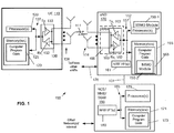
- FIG. 1 this figure shows a block diagram of an exemplary system in which the exemplary embodiments may be practiced.
- UE 110 is in wireless communication with a wireless network 100.
- the UE 110 includes one or more processors 120, one or more memories 125, and one or more transceivers 130 interconnected through one or more buses 127.
- Each of the one or more transceivers 130 includes a receiver, Rx, 132 and a transmitter, Tx, 133.
- the one or more buses 127 may be address, data, or control buses, and may include any interconnection mechanism, such as a series of lines on a motherboard or integrated circuit, fiber optics or other optical communication equipment, and the like.
- the one or more transceivers 130 are connected to one or more antennas 128.
- the one or more memories 125 include computer program code 123.
- Each UE 110 communicates with eNB 170 via a wireless link 111, and there are N wireless links shown.
- the eNB 170 is a base station that provides access by wireless devices such as the UE 110 to the wireless network 100.
- the eNB 170 includes one or more processors 152, one or more memories 155, one or more network interfaces (N/W I/F(s)) 161, and one or more transceivers 160 interconnected through one or more buses 157.
- Each of the one or more transceivers 160 includes a receiver, Rx, 162 and a transmitter, Tx, 163.
- the one or more transceivers 160 are connected to multiple (e.g., many) antennas 158.
- the one or more memories 155 include computer program code 153.
- the eNB 170 includes a MIMO module 150, comprising one of or both parts 150-1 and/or 150-2, which may be implemented in a number of ways.
- the MIMO module 150 may be implemented in hardware as MIMO module 150-1, such as being implemented as part of the one or more processors 152.
- the MIMO module 150-1 may be implemented also as an integrated circuit or through other hardware such as a programmable gate array.
- the MIMO module 150 may be implemented as MIMO module 150-2, which is implemented as computer program code 153 and is executed by the one or more processors 152.
- the one or more memories 155 and the computer program code 153 are configured to, with the one or more processors 152, cause the eNB 170 to perform one or more of the operations as described herein.
- the one or more network interfaces 161 communicate over a network such as via the links 176 and 131.
- Two or more eNBs 170 communicate using, e.g., link 176.
- the link 176 may be wired or wireless or both and may implement, e.g., an X2 interface.
- the one or more buses 157 may be address, data, or control buses, and may include any interconnection mechanism, such as a series of lines on a motherboard or integrated circuit, fiber optics or other optical communication equipment, wireless channels, and the like.
- the one or more transceivers 160 may be implemented as a remote radio head (RRH) 195, with the other elements of the eNB 170 being physically in a different location from the RRH, and the one or more buses 157 could be implemented in part as fiber optic cable to connect the other elements of the eNB 170 to the RRH 195.
- RRH remote radio head
- the wireless network 100 may include a network control element (NCE) 190 that may include MME/SGW functionality, and which provides connectivity with a further network, such as a telephone network and/or a data communications network (e.g., the Internet).
- the eNB 170 is coupled via a link 131 to the NCE 190.
- the link 131 may be implemented as, e.g., an S1 interface.
- the NCE 190 includes one or more processors 175, one or more memories 171, and one or more network interfaces (N/W I/F(s)) 180, interconnected through one or more buses 185.
- the one or more memories 171 include computer program code 173.
- the one or more memories 171 and the computer program code 173 are configured to, with the one or more processors 175, cause the NCE 190 to perform one or more operations.
- the wireless network 100 may implement network virtualization, which is the process of combining hardware and software network resources and network functionality into a single, software-based administrative entity, a virtual network.
- Network virtualization involves platform virtualization, often combined with resource virtualization.
- Network virtualization is categorized as either external, combining many networks, or parts of networks, into a virtual unit, or internal, providing network-like functionality to software containers on a single system. Note that the virtualized entities that result from the network virtualization are still implemented, at some level, using hardware such as processors 152 or 175 and memories 155 and 171, and also such virtualized entities create technical effects.
- the computer readable memories 125, 155, and 171 may be of any type suitable to the local technical environment and may be implemented using any suitable data storage technology, such as semiconductor based memory devices, flash memory, magnetic memory devices and systems, optical memory devices and systems, fixed memory and removable memory.
- the processors 120, 152, and 175 may be of any type suitable to the local technical environment, and may include one or more of general purpose computers, special purpose computers, microprocessors, digital signal processors (DSPs) and processors based on a multi-core processor architecture, as non-limiting examples.
- the various embodiments of the user equipment 110 can include, but are not limited to, cellular telephones such as smart phones, personal digital assistants (PDAs) having wireless communication capabilities, portable computers having wireless communication capabilities, image capture devices such as digital cameras having wireless communication capabilities, gaming devices having wireless communication capabilities, music storage and playback appliances having wireless communication capabilities, Internet appliances permitting wireless Internet access and browsing, tablets with wireless communication capabilities, as well as portable units or terminals that incorporate combinations of such functions.
- PDAs personal digital assistants
- portable computers having wireless communication capabilities
- image capture devices such as digital cameras having wireless communication capabilities
- gaming devices having wireless communication capabilities
- music storage and playback appliances having wireless communication capabilities
- Internet appliances permitting wireless Internet access and browsing, tablets with wireless communication capabilities, as well as portable units or terminals that incorporate combinations of such functions.
- Exemplary embodiments relate to the addition of massive MIMO arrays with constrained RFs to existing antenna arrays with high end RFs in a wireless network, and the distributed implementation of jointly designing the precoders for antenna elements (AEs) connected to constrained RF-chains and high-end RF-chains.
- AEs antenna elements
- constrained RF-chains may have, for example, digital-to-analog converters (DACs) with limited bit resolution, cheaper amplifiers with a small operating region, and/or relaxed analog filters.
- DACs digital-to-analog converters
- US Patent No. 9,231,676 which describes combining low cost RF chains and high end RF chains, thus providing a low cost implementation of massive MIMO antenna arrays with potentially hundreds or more antenna elements.
- the combination of low cost frontends with high accuracy RF chains provides high performance due to the high end RF chains while maintaining low cost due to high number of extremely low cost RF chains.
- the precoder design for the constrained RFs should take into account that the high end RFs can compensate for the limitations in the constrained RFs.
- Embodiments, herein relate to jointly designing the precoder for the constrained and high end RF in a decentralized way.
- embodiments described herein iteratively construct a desired signal at the receivers by determining the precoding coefficients for the constrained RFs one after another taking into account at each iterative step that the high end RFs are capable of producing high resolution signals and could compensate for certain errors.
- the desired signal may mapped to a signal subspace.
- an ellipsoid or polytope may be used depending on the transmit power constraint of the high end RFs.
- the subspace represents the union of the desired signal and all the errors that can be compensated by the high end RFs.
- the constrained RFs' precoding coefficients are used to generate a signal point lying in this subspace. Within this subspace the high end RFs can fully compensate for the difference between the desired signal and the signal point constructed by constrained RFs.
- the set of constrained and high end RFs may be either co-located or distributed.
- the high end RFs may be placed at typical macro sites, while the constrained RF panels may be placed somewhere within the cell, e.g., similar to how small cells are placed.
- it may be necessary to coordinate the independently running precoding algorithms for the high end and the constrained RFs i.e., to exchange information about the achievable subspace region of the high end RF AEs, defined, e.g., by the maximum full RF power, and vice versa to inform the precoder at the high end RF site about the precoding strategy being used to reach the subspace or to get close to the subspace.
- This information may be exchanged over the X2 interface for proper precoder alignment to allow for a distributed simultaneous calculation of the precoder weights.
- the high end RFs may share channel coefficients to the constrained RFs through, e.g., the X2 interface.
- the constrained RFs may then determine their precoding coefficients based on this information. Afterwards, the constrained RFs may communicate the error or difference in signal that the high end RFs need to compensate for. In some embodiments, the constrained RFs could communicate the error to the desired signal that the high end RFs need to use, while other embodiments communicate the optimum precoder coefficients.
- this figure shows an example first antenna array 202 having constrained antenna elements (AE) and an example second antenna array 210 having high end AEs in accordance with exemplary embodiments.
- AE constrained antenna elements
- antenna elements 205-1 through 205-30 there are thirty antenna elements 205-1 through 205-30 (i.e., a 5x6 array of antennas in this example) for the first antenna array 202, and four AEs 215-1 through 215-4 (i.e., a 2x2 array of antennas in this example) for the first antenna array 202.
- the antenna arrays 202 and 210 may be located at different locations, for example, at different base stations. However, it is noted that the antenna array may also be collocated as shown by antenna array 211 for example. It is noted that the number of AEs in the example shown in FIG. 2 is not intended to be limiting, and more or less AEs may be used.
- the antenna elements are also referred to as antennas (e.g., each antenna element is an antenna), and any antenna configuration for such antenna elements may be used.
- FIG. 2 also indicates that antenna elements 205-1 to 205-30 are connected to constrained RF chains, and that the antenna elements of antenna array 210 are connected to four high end RF chains 215-1 through 215-4.
- Embodiments discussed herein provide an optimal way of integrating the high end RF chains into any algorithm that determines the precoding coefficients of the constrained RF chains.
- the benefits of the proposed concept are a very high performance in terms of number of served users as well as the residual mean squared error (MSE), even in case of a very limited number of high end RF frontends.
- MSE residual mean squared error
- One application could be to use the high end RFs from an available macro site having, for example, just 4 RF front ends as shown in FIG. 2 , and adding a low cost constrained RF panel directly at the site or somewhere in the cell. In such an example configuration up to ten user equipment could be served.
- Knapsack algorithm as well as the subspace approach will lead to limited processing overhead.
- the concept of over the air signal generation aims at transmitting signals from antenna elements such that when multiplied by the channel response, they result in the desired signal at the receiver (Quadrature Amplitude Modulation (QAM) symbols or time samples of OFDM symbol).
- QAM Quadrature Amplitude Modulation
- the desired signals need to be generated simultaneously at all the receivers, and each receiver may have multiple antenna elements.
- Cascading the signal samples from all the AEs of all the UEs at any particular time instant may be represented by a combined signal (vector) of dimension n. In an n- dimensional signal space this combined signal is denoted by a point. Switching on any one of the AE results in a signal point in this n- dimensional space, which corresponds to the channel response at that time instant.
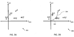
- FIG. 3A and 3B show example signal spaces in accordance with exemplary embodiments.
- the x- and y-axis represent the signal received at UE1 and UE2, respectively.
- the channel seen by the constrained RFs is represented as h1, h2, and h3; the channel seen by the high end RF is represented as h4; and the desired signal point is denoted d.
- the constrained RFs h1, h2, and h3 are assumed to have one bit resolution (i.e.
- h1 to h4 correspond to AE 1 to AE 4.
- this example description can be directly extended to multi-bit amplitude and phase.
- FIG. 3B in the absence of the high end RF h4 , exhaustive search will switch on AE 1 and 3 (represented by the circles surrounding h1 and h3 respectively) to construct a signal as close as possible to d .
- the vector 302 and the vector 304 correspond to h1 and h3 , respectively in this example.
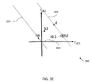
- FIG. 3C this figure shows example signal space 300 and amplitude values that can be constructed at the receiver when a high end RF is present.
- the high end RF corresponds to point h4.
- the amplitude values that can be constructed at the high end RF are represented by line 320 through the origin of the signal space 300.
- the length of the line 320 varies depending on the transmit power constraint for this AE.
- the dotted line 325 in FIG. 3C shows the line 320 shifted to desired signal point d .
- the dotted line 325 represents the errors that can be corrected by the high end RF h4.
- the desired signal point d can be reached by using the high end RF, it is sufficient for the constrained RFs during each iteration to switch on the AE that will result in a point close to the line.
- the AE 2 is switched on as shown by vector 330.
- a few number of amplitude and phase bits can be transmitted from each constrained RF AE and hence, the points h1, h2, and h3 can be scaled by a discrete complex value to construct d .
- the line 320 in FIG. 3C would be a parallelogram or ellipse for case the AEs have individual or total power constraints, respectively.
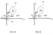
- An example with two AEs namely, AE 4 and AE 5 each connected to one high end RF is shown in FIG 3D and FIG 3E for individual and total power constraints, respectively.
- the points h4 and h5 in FIGS. 3D and 3E correspond to AE 4 and AE 5 respectively.
- the size of the parallelogram 340 shown in FIG. 3D and the size of the size of the ellipse 345 shown in FIG. 3E are proportional to the power available at the transmitter.
- the length of the sides of the parallelogram 340 which are parallel to line 341 are proportional to the individual transmit power of AE 5
- the length of the sides of the parallelogram 340 that are parallel to line 342 are proportional to the individual transmit power of AE 4.
- the size of the ellipse 345 shown in FIG. 3E is proportional to the total transmit power of AE 4 and AE 5. Without the transmit power constraint (i.e. with infinite power) the projection area will be the complete two dimensional subspace spanned by the signal received at UE1 and UE2.
- each search step further includes accounting for the fact that the high end RFs can be used to produce high resolution signals to compensate for the difference between the desired signal, d , and the signal generated over the air using the constrained RFs. It is noted that the Knapsack algorithm is suboptimal as it looks for the best AE in each step sequentially; whereas combining the high end RF is optimal as the influence of all the high end RFs are taken into account in each step.
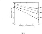
- FIG. 4 shows MSE as a function of increasing the number of constrained RFs in accordance with exemplary embodiments.
- MSE performance according to exemplary embodiments described herein is indicated by line 408 for the case of 10 UEs served by a base station with 4 high end RFs and varying number of constrained RFs.
- the line 404 shows the case where only the constrained RFs is used and the AEs are chosen based on knapsack (KS) algorithm.
- Line 406 shows the MSE for the case where first the AE with constrained RFs are chosen based on KS and then the high end RFs are used to minimize the remaining MSE in a single step.
- KS knapsack
- Line 402 shows the algorithm where the ZF coefficients are quantized for the constrained RFs (e.g. as described in US Patent No. 9,231,676 ). It can be seen that line 408 shows an 11 dB better performance than line 402 corresponding to the reference algorithm when 96 constrained RFs and 4 high end RFs are utilized. It is noted that no power constraint has been considered in FIG. 4 with respect to line 402.
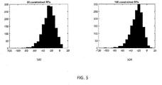
- FIG. 5 this figure shows two bar graphs showing distribution of transmit power for high end RFs in dBW in accordance with exemplary embodiments.
- the first bar graph 502 is for 20 constrained RFs and the second graph 504 is for 100 constrained RFs.
- 0 dBW corresponds to maximum transmit power per AE. It can be seen that for most of the cases the transmit power constraint is satisfied automatically.
- the capacity providing AEs may corresponds to AEs whose instantaneous channel coefficients help in moving towards the high end RF subspace during the iterative steps.
- the energy saving AEs are the AEs whose instantaneous channel coefficients help in moving within the high end RF subspace there by reducing the power required by the high end RFs.
- the coefficients of the different groups can be weighted differently in order to either save energy of the high end RFs or increase the capacity of the system.
- this grouping could be used to reduce the computational complexity by choosing the AEs in each group after the other group AEs.
- the energy saving AEs are designed first and then the capacity providing RFs.
- the capacity maximization mode the order is reversed.
- the channel coefficients from the energy saving AEs could be updated less often than that of other AEs, which can be triggered by the base station.
- FIG. 6 is a logic flow diagram for precoder design for combining high-end RF with constrained RF of massive MIMO antennas. This figure further illustrates the operation of an exemplary method or methods, a result of execution of computer program instructions embodied on a computer readable memory, functions performed by logic implemented in hardware, and/or interconnected means for performing functions in accordance with exemplary embodiments.
- the MIMO module 150 may include multiples ones of the blocks in FIG. 6 , where each included block is an interconnected means for performing the function in the block.
- the blocks in FIG. 6 are assumed to be performed by a base station such as eNB 170, e.g., under control of the MIMO module 150 at least in part.
- a method may comprise: mapping a signal desired by at least one receiver to a projection area based at least on a functionality corresponding to one or more first radio frequency chains coupled to a plurality of first antennas as indicated by block 602; selecting precoding coefficients for at least one of one or more second radio frequency chains coupled to a plurality of second antennas to generate a signal point within the projection area as indicated by block 604; and compensating for a difference between the generated signal point and the signal desired by the at least one receiver using at least one of the first radio frequency chains, wherein the second radio frequency chains have a reduced functionality relative to the functionality of the first radio frequency chains, and wherein the first and second set of antennas are different as indicated by block 606.
- selecting the precoding coefficients may include: selecting precoding coefficients for at least one of the second radio frequency chains for generating a signal point closest to the projection area.
- the first antennas and the second antennas may be collocated.
- the first antennas may be in a different location than the second antennas.
- the first antennas may be located at a first base station and the second antennas may be located at a second base station, and the first base station may provide a larger cell than the second base station.
- the method may include receiving, from the first base station via an X2 interface, configuration information for the one or more first radio frequency chains for mapping the desired signal to the projection area.
- the method may include receiving, from the second base station via an X2 interface, information for determining the difference between the generated signal point and the signal desired for compensating for the difference.
- the functionality of the first radio frequency chains may be based at least in part on a plurality of features and the second radio frequency chains may have a reduced functionality because one or more features for the second radio frequency chains are relaxed relative to identical one or more features for the first radio frequency chains.
- the features may correspond to at least one of: transmission power, amplifier character like operating region, bit resolution, and analog filters.
- a shape of the projection area may be based on at least one of: the number of first radio frequency chains, a total power constraint of the one or more antenna elements, individual power constraints of each of the one or more antenna elements, and the channel coefficient of each of the one or more antenna elements; and a size of the projection area may be based on at least one of: a total power constraint of the one or more antenna elements, and individual power constraints of each of the one or more antenna elements, the channel coefficient of each of the one or more antenna elements.
- the shape of the projection area may be at least one of: a subspace, an ellipsoid, and a polytope.
- an apparatus may comprise at least one processor; and at least one memory including computer program code, the at least one memory and the computer program code configured to, with the at least one processor, cause the apparatus to perform at least the following: map a signal desired by at least one receiver to a projection area based at least on a functionality corresponding to one or more first radio frequency chains coupled to a plurality of first antennas; select precoding coefficients for at least one of one or more second radio frequency chains coupled to a plurality of second antennas to generate a signal point within the projection area; and compensate for a difference between the generated signal point and the signal desired by the at least one receiver using at least one of the first radio frequency chains, wherein the second radio frequency chains have a reduced functionality relative to the functionality of the first radio frequency chains, and wherein the first and second set of antennas are different.
- selection of the precoding coefficients may include: selecting precoding coefficients for at least one of the second radio frequency chains for generating a signal point closest to the projection area.
- the first antennas and the second antennas may be collocated.
- the apparatus may be a base station and may further comprise at least one of: the first antennas and the second antennas. At least one of the first antennas and the second antennas may be located at another base station.
- the at least one memory and the computer program code may be configured to, with the at least one processor, cause the apparatus to perform: receiving, from the first base station via an X2 interface, configuration information for the one or more first radio frequency chains for mapping the desired signal to the projection area.
- the at least one memory and the computer program code may be configured to, with the at least one processor, cause the apparatus to perform: receive, from the second base station via an X2 interface, information for determining the difference between the generated signal point and the signal desired for compensating for the difference.
- the functionality of the first radio frequency chains may be based at least in part on a plurality of features and wherein the second radio frequency chains may have a reduced functionality because one or more features for the second radio frequency chains are relaxed relative to identical one or more features for the first radio frequency chains.
- the features may correspond to at least one of: transmission power, amplifier character like operating region, bit resolution, and analog filters.
- a computer program product may comprise a non-transitory computer-readable medium storing computer program code thereon which when executed by a device causes the device to perform at least: mapping a signal desired by at least one receiver to a projection area based at least on a functionality corresponding to one or more first radio frequency chains coupled to a plurality of first antennas; selecting precoding coefficients for at least one of one or more second radio frequency chains coupled to a plurality of second antennas to generate a signal point within the projection area; and compensating for a difference between the generated signal point and the signal desired by the at least one receiver using at least one of the first radio frequency chains, wherein the second radio frequency chains have a reduced functionality relative to the functionality of the first radio frequency chains, and wherein the first and second set of antennas are different.
- a technical effect of one or more of the example embodiments disclosed herein is 10 UEs can be supported using only 4 high end RFs and MSE up to -17 dB is achievable with 96 constrained RFs.
- Another technical effect of one or more of the example embodiments disclosed herein is, in comparison to having only constrained RFs, few high end RFs with high precision helps in achieving minimizing the error to a large extent.
- Another technical effect of one or more of the example embodiments disclosed herein is, in comparison to having only Full RF, now less power will be necessary due to the diversity gain introduced due to the constrained RF chain AEs.
- Another technical effect of one or more of the example embodiments disclosed herein is different power constraints namely, maximum power constraint or total power constraint can be addressed. Depending on the power constraint the projection area where the desired signal is projected will change.
- the proposed invention can be used in all these cases.
- Embodiments herein may be implemented in software (executed by one or more processors), hardware (e.g., an application specific integrated circuit), or a combination of software and hardware.
- the software e.g., application logic, an instruction set
- a "computer-readable medium” may be any media or means that can contain, store, communicate, propagate or transport the instructions for use by or in connection with an instruction execution system, apparatus, or device, such as a computer, with one example of a computer described and depicted, e.g., in FIG. 1 .
- a computer-readable medium may comprise a computer-readable storage medium (e.g., memories 125, 155, 171 or other device) that may be any media or means that can contain, store, and/or transport the instructions for use by or in connection with an instruction execution system, apparatus, or device, such as a computer.
- a computer-readable storage medium does not comprise propagating signals.
- the different functions discussed herein may be performed in a different order and/or concurrently with each other. Furthermore, if desired, one or more of the above-described functions may be optional or may be combined.
Landscapes
- Engineering & Computer Science (AREA)
- Computer Networks & Wireless Communication (AREA)
- Signal Processing (AREA)
- Physics & Mathematics (AREA)
- Mathematical Physics (AREA)
- Radio Transmission System (AREA)
- Mobile Radio Communication Systems (AREA)
Claims (10)
- Verfahren, umfassend:Abbilden (602) eines von mindestens einem Empfänger gewünschten Signals auf einen Projektionsbereich basierend auf mindestens einer Funktionalität, die einer oder mehreren ersten Hochfrequenzketten entspricht, die mit einer Mehrzahl von ersten Antennen (215-1, 215-2, 215-3, 215-4) gekoppelt sind;Auswählen (604) von Vorcodierkoeffizienten für mindestens eine von einer oder mehreren zweiten Hochfrequenzketten, die mit einer Mehrzahl von zweiten Antennen (205-1 - 205-30) gekoppelt sind, um einen Signalpunkt innerhalb des Projektionsbereichs zu erzeugen; undKompensieren (606) einer Differenz zwischen dem erzeugten Signalpunkt und dem von dem mindestens einen Empfänger gewünschten Signal unter Verwendung mindestens einer der Hochfrequenzketten, wobei der Projektionsbereich einen Bereich bezeichnet, innerhalb dessen die Differenz zwischen dem erzeugten Signalpunkt und dem von dem mindestens einen Empfänger gewünschten Signal unter Verwendung der einen oder der mehreren ersten Hochfrequenzketten, die mit der Mehrzahl von ersten Antennen (215-1, 215-2, 215-3, 215-4) gekoppelt sind, kompensiert werden kann,wobei die zweiten Hochfrequenzketten eine reduzierte Funktionalität bezüglich der Funktionalität der ersten Hochfrequenzketten aufweisen, und wobei der erste und der zweite Satz von Antennen verschieden sind, wobei die Funktionalität der ersten Hochfrequenzketten wenigstens zum Teil auf einer Mehrzahl von Merkmalen basiert, und wobei die zweiten Hochfrequenzketten eine reduzierte Funktionalität aufweisen, da ein oder mehrere Merkmale für die zweiten Hochfrequenzketten bezüglich eines oder mehrerer identischer Merkmale der ersten Hochfrequenzketten relaxiert sind, wobei die Merkmale mindestens eines umfassen von: Sendeleistung, Verstärkereigenschaft wie Betriebsbereich, Bitauflösung und Analogfilter.
- Verfahren nach Anspruch 1, wobei das Auswählen der Vorcodierkoeffizienten, falls die eine oder die mehreren zweiten Hochfrequenzketten nicht zum Erzeugen eines Signalpunkts innerhalb des Projektionsbereichs imstande sind, umfasst:
Auswählen von Vorcodierkoeffizienten für mindestens eine der zweiten Hochfrequenzketten zum Erzeugen eines Signalpunkts, der dem Projektionsbereich am nächsten ist. - Verfahren nach Anspruch 1, wobei die ersten Antennen und die zweiten Antennen ortsgleich angeordnet sind.
- Verfahren nach Anspruch 1, wobei die ersten Antennen an einem anderen Ort als die zweiten Antennen angeordnet sind.
- Verfahren nach Anspruch 4, wobei die ersten Antennen an einer ersten Basisstation angeordnet sind, und die zweiten Antennen an einer zweiten Basisstation angeordnet sind, und wobei die erste Basisstation eine größere Zelle als die zweite Basisstation bereitstellt.
- Verfahren der Ansprüche 4, wobei das Verfahren ferner eines umfasst von:Empfangen von Konfigurationsinformationen von der ersten Basisstation über eine X2-Schnittstelle für die eine oder die mehreren ersten Hochfrequenzketten zum Abbilden des gewünschten Signals auf einen Projektionsbereich; undEmpfangen von Informationen von der zweiten Basisstation über eine X2-Schnittstelle zum Bestimmen der Differenz zwischen dem erzeugten Signalpunkt und dem zur Kompensation der Differenz gewünschten Signal.
- Verfahren nach Anspruch 1, wobei:eine Form des Projektionsbereich auf mindestens einem basiert von: der Anzahl von ersten Hochfrequenzketten, einer Gesamtleistungsbeschränkung der einen oder der mehreren ersten Antennen, individuellen Leistungsbeschränkungen jeder der einen oder der mehreren ersten Antennen und dem Kanalkoeffizienten jeder der einen oder der mehreren ersten Antennen; undeine Größe des Projektionsbereich auf mindestens einem basiert von: einer Gesamtleistungsbeschränkung der einen oder der mehreren ersten Antennen und individuellen Leistungsbeschränkungen jeder der einen oder der mehreren ersten Antennen sowie dem Kanalkoeffizienten jeder der einen oder der mehreren ersten Antennen.
- Verfahren nach Anspruch 1, wobei die Form des Projektionsbereichs mindestens eines ist von: einem Teilraum, einem Ellipsoid und einem Polytop.
- Vorrichtung, umfassend Mittel zum Durchführen des Verfahrens nach einem der Ansprüche 1 bis 8.
- Computerprogrammprodukt für einen Computer, umfassend Softwarecodeabschnitte zum Ausführen der Schritte nach einem der Ansprüche 1 bis 8, wenn das Produkt auf dem Computer ausgeführt wird.
Applications Claiming Priority (1)
| Application Number | Priority Date | Filing Date | Title |
|---|---|---|---|
| US15/355,421 US9979458B1 (en) | 2016-11-18 | 2016-11-18 | Precoder design for combining high-end RF with constrained RF of massive MIMO antennas |
Publications (2)
| Publication Number | Publication Date |
|---|---|
| EP3324552A1 EP3324552A1 (de) | 2018-05-23 |
| EP3324552B1 true EP3324552B1 (de) | 2020-03-04 |
Family
ID=60201824
Family Applications (1)
| Application Number | Title | Priority Date | Filing Date |
|---|---|---|---|
| EP17197681.4A Active EP3324552B1 (de) | 2016-11-18 | 2017-10-23 | Vorcodiererentwurf zum kombinieren von high-end-hf-antennen mit beschränkten hf-antennen für massives mimo |
Country Status (3)
| Country | Link |
|---|---|
| US (1) | US9979458B1 (de) |
| EP (1) | EP3324552B1 (de) |
| CN (1) | CN108075816B (de) |
Families Citing this family (8)
| Publication number | Priority date | Publication date | Assignee | Title |
|---|---|---|---|---|
| US11240879B2 (en) * | 2017-01-06 | 2022-02-01 | Parallel Wireless, Inc. | X2 brokering with aggregation optimization |
| KR102531563B1 (ko) * | 2017-01-06 | 2023-05-12 | 패러렐 와이어리스, 인크. | 집성 최적화를 통한 x2 중재 |
| EP3785487A4 (de) * | 2018-04-24 | 2021-12-15 | Parallel Wireless, Inc. | Xx-brokering mit aggregationsoptimierung |
| EP3954055A1 (de) | 2019-04-12 | 2022-02-16 | Telefonaktiebolaget LM Ericsson (publ) | Online-mimo-drahtlosnetzwerkvirtualisierung mit unbekannter kanalinformation |
| US11979206B2 (en) | 2020-02-14 | 2024-05-07 | Telefonaktiebolaget Lm Ericsson (Publ) | Online convex optimization with periodic updates for downlink multi-cell MIMO wireless network virtualization |
| EP4197241B1 (de) * | 2020-08-14 | 2025-10-01 | Telefonaktiebolaget LM Ericsson (publ) | Verzögerungstolerante eingeschränkte online-konvexoptimierung |
| EP3968526A1 (de) | 2020-09-14 | 2022-03-16 | Nokia Technologies Oy | Hochfrequenzübertragungsketten |
| EP4270795B1 (de) * | 2022-04-28 | 2025-03-12 | Nokia Solutions and Networks Oy | Schätzung und reduzierung des hf-kettenversatzes |
Family Cites Families (14)
| Publication number | Priority date | Publication date | Assignee | Title |
|---|---|---|---|---|
| US20010016504A1 (en) | 1998-04-03 | 2001-08-23 | Henrik Dam | Method and system for handling radio signals in a radio base station |
| US7400191B2 (en) | 2006-04-07 | 2008-07-15 | Manuel De Jesus Rodriguez | Switching power amplifier |
| WO2009005768A1 (en) | 2007-06-28 | 2009-01-08 | Parkervision, Inc. | Systems and methods of rf power transmission, modulation, and amplification |
| JP5277246B2 (ja) | 2007-07-16 | 2013-08-28 | ノーテル・ネットワークス・リミテッド | 無線ネットワークでの空間分割多重アクセスの提供 |
| US8289203B2 (en) | 2009-06-26 | 2012-10-16 | Src, Inc. | Radar architecture |
| WO2012152306A1 (en) | 2011-05-06 | 2012-11-15 | Nokia Siemens Networks Oy | Arrangements for controlling antennas |
| US9749935B2 (en) | 2012-03-09 | 2017-08-29 | Samsung Electronics Co., Ltd. | Methods and apparatus for cell scanning in system with large number of antennas |
| US20130286960A1 (en) | 2012-04-30 | 2013-10-31 | Samsung Electronics Co., Ltd | Apparatus and method for control channel beam management in a wireless system with a large number of antennas |
| CN102710278A (zh) * | 2012-06-01 | 2012-10-03 | 天津里外科技有限公司 | Td-lte/td-scdma射频前端收发器系统 |
| JP6038330B2 (ja) * | 2012-10-03 | 2016-12-07 | ゼットティーイー ウィストロン テレコム エービー | 無線ネットワークにおける送信アンテナの動的再構成 |
| US9516563B2 (en) | 2013-01-21 | 2016-12-06 | Intel Corporation | Apparatus, system and method of handover of a beamformed link |
| US9768501B2 (en) | 2013-01-21 | 2017-09-19 | Intel Corporation | Apparatus, system and method of steering an antenna array |
| US9231676B2 (en) * | 2014-05-12 | 2016-01-05 | Nokia Solutions And Networks Oy | Low effort massive MIMO antenna arrays and their use |
| WO2016115545A2 (en) * | 2015-01-16 | 2016-07-21 | Ping Liang | Beamforming in a mu-mimo wireless communication system with relays |
-
2016
- 2016-11-18 US US15/355,421 patent/US9979458B1/en active Active
-
2017
- 2017-10-23 EP EP17197681.4A patent/EP3324552B1/de active Active
- 2017-11-17 CN CN201711145434.0A patent/CN108075816B/zh active Active
Non-Patent Citations (1)
| Title |
|---|
| None * |
Also Published As
| Publication number | Publication date |
|---|---|
| US20180145739A1 (en) | 2018-05-24 |
| CN108075816B (zh) | 2021-07-13 |
| CN108075816A (zh) | 2018-05-25 |
| EP3324552A1 (de) | 2018-05-23 |
| US9979458B1 (en) | 2018-05-22 |
Similar Documents
| Publication | Publication Date | Title |
|---|---|---|
| EP3324552B1 (de) | Vorcodiererentwurf zum kombinieren von high-end-hf-antennen mit beschränkten hf-antennen für massives mimo | |
| Huang et al. | Decentralized beamforming design for intelligent reflecting surface-enhanced cell-free networks | |
| WO2019156512A1 (en) | Method and apparatus for wideband csi reporting in an advanced wireless communication system | |
| US10917161B2 (en) | Electronic device and method for wireless communication | |
| JP6474889B2 (ja) | Mimo送信機の前処理フィルタを用いた伝送信号生成方法 | |
| WO2022008801A1 (en) | Group-based beam reporting for multi-trp operation | |
| WO2016200121A1 (ko) | 위치 정보 송수신을 위한 방법 및 장치 | |
| CN117099322A (zh) | 宽带通信的波束斜视的解决方案 | |
| CN107872259B (zh) | 一种码本生成方法和通信设备 | |
| WO2018228356A1 (zh) | 通道校正的方法和网络设备 | |
| WO2020070008A1 (en) | Dynamic signaling of coherence levels | |
| CN119497968A (zh) | 用于无线通信系统中的多发送接收点操作的csi码本 | |
| WO2024155071A1 (en) | A method and an apparatus for group partitioning in a multi-user mimo system in a wireless communication system | |
| Nguyen et al. | Joint beamforming design and base‐station assignment in a coordinated multicell system | |
| CN111418162B (zh) | 利用参考权重向量的ue特定的波束映射 | |
| JP5968523B2 (ja) | 不均一系における適応型チャネル方向情報フィードバックのための方法及び装置 | |
| CN119945502A (zh) | 用于同时多面板pucch的方法 | |
| CN115473589A (zh) | 一种校准处理方法、装置及设备 | |
| WO2020015874A1 (en) | Exploiting receiver antenna correlation in spatial compression based csi feedback scheme | |
| AU2017305260A1 (en) | Electronic device and method for use in network control point and central processing node | |
| WO2024191084A1 (en) | Method and device for scalable 2-d joint phase-time arrays and beamforming operation | |
| WO2024248471A1 (en) | Polar codes with partial repetition | |
| WO2025019965A9 (en) | Devices, methods, apparatuses, and computer readable media for massive multiple input multiple output | |
| WO2026035003A1 (en) | Adaptive multi-level envelope tracking design for digital envelope trackers | |
| WO2026059205A1 (en) | Method and apparatus for artificial intelligence based channel inpainting in wireless communication systems |
Legal Events
| Date | Code | Title | Description |
|---|---|---|---|
| PUAI | Public reference made under article 153(3) epc to a published international application that has entered the european phase |
Free format text: ORIGINAL CODE: 0009012 |
|
| STAA | Information on the status of an ep patent application or granted ep patent |
Free format text: STATUS: THE APPLICATION HAS BEEN PUBLISHED |
|
| AK | Designated contracting states |
Kind code of ref document: A1 Designated state(s): AL AT BE BG CH CY CZ DE DK EE ES FI FR GB GR HR HU IE IS IT LI LT LU LV MC MK MT NL NO PL PT RO RS SE SI SK SM TR |
|
| AX | Request for extension of the european patent |
Extension state: BA ME |
|
| RIN1 | Information on inventor provided before grant (corrected) |
Inventor name: STAUDACHER, MARKUS Inventor name: SIVASIVA GANESAN, RAKASH Inventor name: PANZNER, BERTHOLD Inventor name: ZIRWAS, WOLFGANG |
|
| STAA | Information on the status of an ep patent application or granted ep patent |
Free format text: STATUS: REQUEST FOR EXAMINATION WAS MADE |
|
| 17P | Request for examination filed |
Effective date: 20181123 |
|
| RBV | Designated contracting states (corrected) |
Designated state(s): AL AT BE BG CH CY CZ DE DK EE ES FI FR GB GR HR HU IE IS IT LI LT LU LV MC MK MT NL NO PL PT RO RS SE SI SK SM TR |
|
| RAP1 | Party data changed (applicant data changed or rights of an application transferred) |
Owner name: NOKIA SOLUTIONS AND NETWORKS OY |
|
| GRAP | Despatch of communication of intention to grant a patent |
Free format text: ORIGINAL CODE: EPIDOSNIGR1 |
|
| STAA | Information on the status of an ep patent application or granted ep patent |
Free format text: STATUS: GRANT OF PATENT IS INTENDED |
|
| INTG | Intention to grant announced |
Effective date: 20190927 |
|
| RIC1 | Information provided on ipc code assigned before grant |
Ipc: H04B 7/06 20060101ALN20190913BHEP Ipc: H04B 7/0456 20170101AFI20190913BHEP Ipc: H04B 7/022 20170101ALN20190913BHEP |
|
| GRAS | Grant fee paid |
Free format text: ORIGINAL CODE: EPIDOSNIGR3 |
|
| GRAA | (expected) grant |
Free format text: ORIGINAL CODE: 0009210 |
|
| STAA | Information on the status of an ep patent application or granted ep patent |
Free format text: STATUS: THE PATENT HAS BEEN GRANTED |
|
| AK | Designated contracting states |
Kind code of ref document: B1 Designated state(s): AL AT BE BG CH CY CZ DE DK EE ES FI FR GB GR HR HU IE IS IT LI LT LU LV MC MK MT NL NO PL PT RO RS SE SI SK SM TR |
|
| REG | Reference to a national code |
Ref country code: GB Ref legal event code: FG4D |
|
| REG | Reference to a national code |
Ref country code: CH Ref legal event code: EP |
|
| REG | Reference to a national code |
Ref country code: AT Ref legal event code: REF Ref document number: 1241581 Country of ref document: AT Kind code of ref document: T Effective date: 20200315 |
|
| REG | Reference to a national code |
Ref country code: DE Ref legal event code: R096 Ref document number: 602017012514 Country of ref document: DE |
|
| REG | Reference to a national code |
Ref country code: IE Ref legal event code: FG4D |
|
| PG25 | Lapsed in a contracting state [announced via postgrant information from national office to epo] |
Ref country code: RS Free format text: LAPSE BECAUSE OF FAILURE TO SUBMIT A TRANSLATION OF THE DESCRIPTION OR TO PAY THE FEE WITHIN THE PRESCRIBED TIME-LIMIT Effective date: 20200304 Ref country code: NO Free format text: LAPSE BECAUSE OF FAILURE TO SUBMIT A TRANSLATION OF THE DESCRIPTION OR TO PAY THE FEE WITHIN THE PRESCRIBED TIME-LIMIT Effective date: 20200604 Ref country code: FI Free format text: LAPSE BECAUSE OF FAILURE TO SUBMIT A TRANSLATION OF THE DESCRIPTION OR TO PAY THE FEE WITHIN THE PRESCRIBED TIME-LIMIT Effective date: 20200304 |
|
| REG | Reference to a national code |
Ref country code: NL Ref legal event code: MP Effective date: 20200304 |
|
| PG25 | Lapsed in a contracting state [announced via postgrant information from national office to epo] |
Ref country code: BG Free format text: LAPSE BECAUSE OF FAILURE TO SUBMIT A TRANSLATION OF THE DESCRIPTION OR TO PAY THE FEE WITHIN THE PRESCRIBED TIME-LIMIT Effective date: 20200604 Ref country code: HR Free format text: LAPSE BECAUSE OF FAILURE TO SUBMIT A TRANSLATION OF THE DESCRIPTION OR TO PAY THE FEE WITHIN THE PRESCRIBED TIME-LIMIT Effective date: 20200304 Ref country code: GR Free format text: LAPSE BECAUSE OF FAILURE TO SUBMIT A TRANSLATION OF THE DESCRIPTION OR TO PAY THE FEE WITHIN THE PRESCRIBED TIME-LIMIT Effective date: 20200605 Ref country code: LV Free format text: LAPSE BECAUSE OF FAILURE TO SUBMIT A TRANSLATION OF THE DESCRIPTION OR TO PAY THE FEE WITHIN THE PRESCRIBED TIME-LIMIT Effective date: 20200304 Ref country code: SE Free format text: LAPSE BECAUSE OF FAILURE TO SUBMIT A TRANSLATION OF THE DESCRIPTION OR TO PAY THE FEE WITHIN THE PRESCRIBED TIME-LIMIT Effective date: 20200304 |
|
| REG | Reference to a national code |
Ref country code: LT Ref legal event code: MG4D |
|
| PG25 | Lapsed in a contracting state [announced via postgrant information from national office to epo] |
Ref country code: NL Free format text: LAPSE BECAUSE OF FAILURE TO SUBMIT A TRANSLATION OF THE DESCRIPTION OR TO PAY THE FEE WITHIN THE PRESCRIBED TIME-LIMIT Effective date: 20200304 |
|
| PG25 | Lapsed in a contracting state [announced via postgrant information from national office to epo] |
Ref country code: ES Free format text: LAPSE BECAUSE OF FAILURE TO SUBMIT A TRANSLATION OF THE DESCRIPTION OR TO PAY THE FEE WITHIN THE PRESCRIBED TIME-LIMIT Effective date: 20200304 Ref country code: EE Free format text: LAPSE BECAUSE OF FAILURE TO SUBMIT A TRANSLATION OF THE DESCRIPTION OR TO PAY THE FEE WITHIN THE PRESCRIBED TIME-LIMIT Effective date: 20200304 Ref country code: PT Free format text: LAPSE BECAUSE OF FAILURE TO SUBMIT A TRANSLATION OF THE DESCRIPTION OR TO PAY THE FEE WITHIN THE PRESCRIBED TIME-LIMIT Effective date: 20200729 Ref country code: SM Free format text: LAPSE BECAUSE OF FAILURE TO SUBMIT A TRANSLATION OF THE DESCRIPTION OR TO PAY THE FEE WITHIN THE PRESCRIBED TIME-LIMIT Effective date: 20200304 Ref country code: SK Free format text: LAPSE BECAUSE OF FAILURE TO SUBMIT A TRANSLATION OF THE DESCRIPTION OR TO PAY THE FEE WITHIN THE PRESCRIBED TIME-LIMIT Effective date: 20200304 Ref country code: CZ Free format text: LAPSE BECAUSE OF FAILURE TO SUBMIT A TRANSLATION OF THE DESCRIPTION OR TO PAY THE FEE WITHIN THE PRESCRIBED TIME-LIMIT Effective date: 20200304 Ref country code: IS Free format text: LAPSE BECAUSE OF FAILURE TO SUBMIT A TRANSLATION OF THE DESCRIPTION OR TO PAY THE FEE WITHIN THE PRESCRIBED TIME-LIMIT Effective date: 20200704 Ref country code: RO Free format text: LAPSE BECAUSE OF FAILURE TO SUBMIT A TRANSLATION OF THE DESCRIPTION OR TO PAY THE FEE WITHIN THE PRESCRIBED TIME-LIMIT Effective date: 20200304 Ref country code: LT Free format text: LAPSE BECAUSE OF FAILURE TO SUBMIT A TRANSLATION OF THE DESCRIPTION OR TO PAY THE FEE WITHIN THE PRESCRIBED TIME-LIMIT Effective date: 20200304 |
|
| REG | Reference to a national code |
Ref country code: AT Ref legal event code: MK05 Ref document number: 1241581 Country of ref document: AT Kind code of ref document: T Effective date: 20200304 |
|
| REG | Reference to a national code |
Ref country code: DE Ref legal event code: R097 Ref document number: 602017012514 Country of ref document: DE |
|
| PLBE | No opposition filed within time limit |
Free format text: ORIGINAL CODE: 0009261 |
|
| STAA | Information on the status of an ep patent application or granted ep patent |
Free format text: STATUS: NO OPPOSITION FILED WITHIN TIME LIMIT |
|
| PG25 | Lapsed in a contracting state [announced via postgrant information from national office to epo] |
Ref country code: IT Free format text: LAPSE BECAUSE OF FAILURE TO SUBMIT A TRANSLATION OF THE DESCRIPTION OR TO PAY THE FEE WITHIN THE PRESCRIBED TIME-LIMIT Effective date: 20200304 Ref country code: AT Free format text: LAPSE BECAUSE OF FAILURE TO SUBMIT A TRANSLATION OF THE DESCRIPTION OR TO PAY THE FEE WITHIN THE PRESCRIBED TIME-LIMIT Effective date: 20200304 Ref country code: DK Free format text: LAPSE BECAUSE OF FAILURE TO SUBMIT A TRANSLATION OF THE DESCRIPTION OR TO PAY THE FEE WITHIN THE PRESCRIBED TIME-LIMIT Effective date: 20200304 |
|
| 26N | No opposition filed |
Effective date: 20201207 |
|
| PG25 | Lapsed in a contracting state [announced via postgrant information from national office to epo] |
Ref country code: PL Free format text: LAPSE BECAUSE OF FAILURE TO SUBMIT A TRANSLATION OF THE DESCRIPTION OR TO PAY THE FEE WITHIN THE PRESCRIBED TIME-LIMIT Effective date: 20200304 Ref country code: SI Free format text: LAPSE BECAUSE OF FAILURE TO SUBMIT A TRANSLATION OF THE DESCRIPTION OR TO PAY THE FEE WITHIN THE PRESCRIBED TIME-LIMIT Effective date: 20200304 |
|
| REG | Reference to a national code |
Ref country code: CH Ref legal event code: PL |
|
| PG25 | Lapsed in a contracting state [announced via postgrant information from national office to epo] |
Ref country code: MC Free format text: LAPSE BECAUSE OF FAILURE TO SUBMIT A TRANSLATION OF THE DESCRIPTION OR TO PAY THE FEE WITHIN THE PRESCRIBED TIME-LIMIT Effective date: 20200304 Ref country code: LU Free format text: LAPSE BECAUSE OF NON-PAYMENT OF DUE FEES Effective date: 20201023 |
|
| REG | Reference to a national code |
Ref country code: BE Ref legal event code: MM Effective date: 20201031 |
|
| PG25 | Lapsed in a contracting state [announced via postgrant information from national office to epo] |
Ref country code: LI Free format text: LAPSE BECAUSE OF NON-PAYMENT OF DUE FEES Effective date: 20201031 Ref country code: BE Free format text: LAPSE BECAUSE OF NON-PAYMENT OF DUE FEES Effective date: 20201031 Ref country code: CH Free format text: LAPSE BECAUSE OF NON-PAYMENT OF DUE FEES Effective date: 20201031 |
|
| PG25 | Lapsed in a contracting state [announced via postgrant information from national office to epo] |
Ref country code: IE Free format text: LAPSE BECAUSE OF NON-PAYMENT OF DUE FEES Effective date: 20201023 |
|
| PGFP | Annual fee paid to national office [announced via postgrant information from national office to epo] |
Ref country code: FR Payment date: 20210913 Year of fee payment: 5 |
|
| PG25 | Lapsed in a contracting state [announced via postgrant information from national office to epo] |
Ref country code: TR Free format text: LAPSE BECAUSE OF FAILURE TO SUBMIT A TRANSLATION OF THE DESCRIPTION OR TO PAY THE FEE WITHIN THE PRESCRIBED TIME-LIMIT Effective date: 20200304 Ref country code: MT Free format text: LAPSE BECAUSE OF FAILURE TO SUBMIT A TRANSLATION OF THE DESCRIPTION OR TO PAY THE FEE WITHIN THE PRESCRIBED TIME-LIMIT Effective date: 20200304 Ref country code: CY Free format text: LAPSE BECAUSE OF FAILURE TO SUBMIT A TRANSLATION OF THE DESCRIPTION OR TO PAY THE FEE WITHIN THE PRESCRIBED TIME-LIMIT Effective date: 20200304 |
|
| PG25 | Lapsed in a contracting state [announced via postgrant information from national office to epo] |
Ref country code: MK Free format text: LAPSE BECAUSE OF FAILURE TO SUBMIT A TRANSLATION OF THE DESCRIPTION OR TO PAY THE FEE WITHIN THE PRESCRIBED TIME-LIMIT Effective date: 20200304 Ref country code: AL Free format text: LAPSE BECAUSE OF FAILURE TO SUBMIT A TRANSLATION OF THE DESCRIPTION OR TO PAY THE FEE WITHIN THE PRESCRIBED TIME-LIMIT Effective date: 20200304 |
|
| PG25 | Lapsed in a contracting state [announced via postgrant information from national office to epo] |
Ref country code: FR Free format text: LAPSE BECAUSE OF NON-PAYMENT OF DUE FEES Effective date: 20221031 |
|
| PGFP | Annual fee paid to national office [announced via postgrant information from national office to epo] |
Ref country code: GB Payment date: 20250904 Year of fee payment: 9 |
|
| PGFP | Annual fee paid to national office [announced via postgrant information from national office to epo] |
Ref country code: DE Payment date: 20250902 Year of fee payment: 9 |