EP4270795B1 - Schätzung und reduzierung des hf-kettenversatzes - Google Patents
Schätzung und reduzierung des hf-kettenversatzes Download PDFInfo
- Publication number
- EP4270795B1 EP4270795B1 EP23155719.0A EP23155719A EP4270795B1 EP 4270795 B1 EP4270795 B1 EP 4270795B1 EP 23155719 A EP23155719 A EP 23155719A EP 4270795 B1 EP4270795 B1 EP 4270795B1
- Authority
- EP
- European Patent Office
- Prior art keywords
- signal
- sub
- radio
- vector
- radio chain
- Prior art date
- Legal status (The legal status is an assumption and is not a legal conclusion. Google has not performed a legal analysis and makes no representation as to the accuracy of the status listed.)
- Active
Links
Images
Classifications
-
- H—ELECTRICITY
- H04—ELECTRIC COMMUNICATION TECHNIQUE
- H04L—TRANSMISSION OF DIGITAL INFORMATION, e.g. TELEGRAPHIC COMMUNICATION
- H04L27/00—Modulated-carrier systems
- H04L27/26—Systems using multi-frequency codes
- H04L27/2601—Multicarrier modulation systems
- H04L27/2647—Arrangements specific to the receiver only
- H04L27/2655—Synchronisation arrangements
- H04L27/2657—Carrier synchronisation
- H04L27/266—Fine or fractional frequency offset determination and synchronisation
-
- H—ELECTRICITY
- H04—ELECTRIC COMMUNICATION TECHNIQUE
- H04B—TRANSMISSION
- H04B1/00—Details of transmission systems, not covered by a single one of groups H04B3/00 - H04B13/00; Details of transmission systems not characterised by the medium used for transmission
- H04B1/0003—Software-defined radio [SDR] systems, i.e. systems wherein components typically implemented in hardware, e.g. filters or modulators/demodulators, are implented using software, e.g. by involving an AD or DA conversion stage such that at least part of the signal processing is performed in the digital domain
-
- H—ELECTRICITY
- H04—ELECTRIC COMMUNICATION TECHNIQUE
- H04B—TRANSMISSION
- H04B1/00—Details of transmission systems, not covered by a single one of groups H04B3/00 - H04B13/00; Details of transmission systems not characterised by the medium used for transmission
- H04B1/38—Transceivers, i.e. devices in which transmitter and receiver form a structural unit and in which at least one part is used for functions of transmitting and receiving
- H04B1/40—Circuits
-
- H—ELECTRICITY
- H04—ELECTRIC COMMUNICATION TECHNIQUE
- H04B—TRANSMISSION
- H04B1/00—Details of transmission systems, not covered by a single one of groups H04B3/00 - H04B13/00; Details of transmission systems not characterised by the medium used for transmission
- H04B1/02—Transmitters
- H04B1/04—Circuits
- H04B1/0475—Circuits with means for limiting noise, interference or distortion
-
- H—ELECTRICITY
- H04—ELECTRIC COMMUNICATION TECHNIQUE
- H04B—TRANSMISSION
- H04B1/00—Details of transmission systems, not covered by a single one of groups H04B3/00 - H04B13/00; Details of transmission systems not characterised by the medium used for transmission
- H04B1/02—Transmitters
- H04B1/04—Circuits
- H04B1/0483—Transmitters with multiple parallel paths
-
- H—ELECTRICITY
- H04—ELECTRIC COMMUNICATION TECHNIQUE
- H04B—TRANSMISSION
- H04B7/00—Radio transmission systems, i.e. using radiation field
- H04B7/02—Diversity systems; Multi-antenna system, i.e. transmission or reception using multiple antennas
- H04B7/04—Diversity systems; Multi-antenna system, i.e. transmission or reception using multiple antennas using two or more spaced independent antennas
- H04B7/06—Diversity systems; Multi-antenna system, i.e. transmission or reception using multiple antennas using two or more spaced independent antennas at the transmitting station
- H04B7/0686—Hybrid systems, i.e. switching and simultaneous transmission
-
- H—ELECTRICITY
- H04—ELECTRIC COMMUNICATION TECHNIQUE
- H04B—TRANSMISSION
- H04B7/00—Radio transmission systems, i.e. using radiation field
- H04B7/02—Diversity systems; Multi-antenna system, i.e. transmission or reception using multiple antennas
- H04B7/04—Diversity systems; Multi-antenna system, i.e. transmission or reception using multiple antennas using two or more spaced independent antennas
- H04B7/08—Diversity systems; Multi-antenna system, i.e. transmission or reception using multiple antennas using two or more spaced independent antennas at the receiving station
- H04B7/0868—Hybrid systems, i.e. switching and combining
-
- H—ELECTRICITY
- H04—ELECTRIC COMMUNICATION TECHNIQUE
- H04L—TRANSMISSION OF DIGITAL INFORMATION, e.g. TELEGRAPHIC COMMUNICATION
- H04L27/00—Modulated-carrier systems
- H04L27/32—Carrier systems characterised by combinations of two or more of the types covered by groups H04L27/02, H04L27/10, H04L27/18 or H04L27/26
- H04L27/34—Amplitude- and phase-modulated carrier systems, e.g. quadrature-amplitude modulated carrier systems
- H04L27/3405—Modifications of the signal space to increase the efficiency of transmission, e.g. reduction of the bit error rate, bandwidth, or average power
- H04L27/3411—Modifications of the signal space to increase the efficiency of transmission, e.g. reduction of the bit error rate, bandwidth, or average power reducing the peak to average power ratio or the mean power of the constellation; Arrangements for increasing the shape gain of a signal set
-
- H—ELECTRICITY
- H04—ELECTRIC COMMUNICATION TECHNIQUE
- H04L—TRANSMISSION OF DIGITAL INFORMATION, e.g. TELEGRAPHIC COMMUNICATION
- H04L27/00—Modulated-carrier systems
- H04L27/32—Carrier systems characterised by combinations of two or more of the types covered by groups H04L27/02, H04L27/10, H04L27/18 or H04L27/26
- H04L27/34—Amplitude- and phase-modulated carrier systems, e.g. quadrature-amplitude modulated carrier systems
- H04L27/38—Demodulator circuits; Receiver circuits
- H04L27/3818—Demodulator circuits; Receiver circuits using coherent demodulation, i.e. using one or more nominally phase synchronous carriers
Definitions
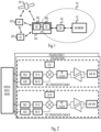
- Various embodiments described herein relate to the field of radio devices with multiple parallel radio frequency (RF) transmitter and/or receiver chains and, particularly, to estimating and correcting gain and phase offsets between the different RF chains.
- RF radio frequency
- MIMO radio devices comprise multiple RF chains, and it would be advantageous if the RF chains had the same phase and gain response, e.g. for the purpose of coherent combining of the different RF chains.
- Each RF chain comprises RF components such as intermediate frequency or RF filters, frequency converters, and amplifiers.
- the response of an RF component, such as gain and phase usually has tolerances which is the main reason why the overall gain-phase of one RF chain might be different from other RF chain, even though they are using identical components.
- the difference in the responses causes degradation of performance in procedures where the signals from the RF chains or the RF chains are combined.
- an apparatus comprising means for performing: capturing a first signal from a first radio chain; dividing samples of the first signal into a first set of sub-vectors according to a determined mapping pattern that maps the samples of the first signal to sub-vectors of the first set; capturing a second signal from a second radio chain, wherein both the first radio chain and the second radio chain are either radio receiver chains or radio transmitter chains; dividing samples of the second signal into a second set of sub-vectors according to the determined mapping pattern; estimate a gain difference and phase difference between each sub-vector of the first set and a respective sub-vector of the second set, thus acquiring sub-vector-level gain differences and sub-vector-level phase differences the first signal and the at least second signal; combining the sub-vector level gain differences to acquire a gain difference between the first signal and the second signal, and combining the sub-vector-level phase differences to acquire a phase difference between the first signal and the second signal; and configuring at least one of the first signal from a first radio chain
- the means are configured to captured first signal simultaneously with the second signal.
- the first signal and the second signal comprise payload data or signalling information from another apparatus.
- the apparatus further comprises a coupling circuitry configured to couple the first radio chain to the second radio chain to form a single radio chain, and wherein the means are configured to captured the first signal and the second signal while the first radio chain is coupled to the second radio chain by the coupling circuitry.
- the first antenna element and the second antenna element are configured to receive the same type of polarization.
- the means comprise at least one processor and at least one memory including computer program code, the at least one memory and computer program code configured to, with the at least one processor, cause the performance of the apparatus.
- the apparatus is for a terminal device of a cellular communication system.
- the apparatus is for an access node of a cellular communication system.
- a method comprises: capturing a first signal from a first radio chain; dividing samples of the first signal into a first set of sub-vectors according to a determined mapping pattern that maps the samples of the first signal to sub-vectors of the first set; capturing a second signal from a second radio chain, wherein both the first radio chain and the second radio chain are either radio receiver chains or radio transmitter chains; dividing samples of the second signal into a second set of sub-vectors according to the determined mapping pattern; estimating a gain difference and phase difference between each sub-vector of the first set and a respective sub-vector of the second set, thus acquiring sub-vector-level gain differences and sub-vector-level phase differences the first signal and the at least second signal; combining the sub-vector level gain differences to acquire a gain difference between the first signal and the second signal, and combining the sub-vector-level phase differences to acquire a phase difference between the first signal and the second signal; and configuring at least one of the first radio chain and the second
- the first radio chain and the second radio chain are radio receiver chains, and the first signal and the second signal are captured after an output of an analog-to-digital converter configured to perform analog-to-digital conversions of the first signal and the second signal.
- the combining comprises averaging the sub-vector-level gain differences and averaging the sub-vector-level phase differences to obtain the gain difference and the phase difference between the first signal and the second signal, respectively.
- the captured first signal has the same total number of samples as the captured second signal, wherein the samples of the first signal and the second signal are indexed, and wherein the mapping pattern maps said indices to the sub-vectors.
- the gain difference and phase difference are estimated by computing a Hermitian multiplication between a first matrix comprising sub-vectors of the first set and a second matrix comprising respective sub-vectors of the second set.
- the first signal is captured simultaneously with the second signal.
- the first signal and the second signal comprise payload data or signalling information from another apparatus.
- the method further comprises coupling, by a coupling circuitry, the first radio chain to the second radio chain to form a single radio chain, and wherein the first signal and the second signal are captured while the first radio chain is coupled to the second radio chain by the coupling circuitry.
- the first antenna element and the second antenna element are configured to receive the same type of polarization.
- the method is performed by a terminal device of a cellular communication system.
- the method is performed by an access node of a cellular communication system.
- a computer program product embodied on a computer-readable medium and comprising a computer program code readable by a computer, wherein the computer program code configures the computer to carry out a computer process comprising: capturing a first signal from a first radio chain; dividing samples of the first signal into a first set of sub-vectors according to a determined mapping pattern that maps the samples of the first signal to sub-vectors of the first set; capturing a second signal from a second radio chain, wherein both the first radio chain and the second radio chain are either radio receiver chains or radio transmitter chains; dividing samples of the second signal into a second set of sub-vectors according to the determined mapping pattern; estimate a gain difference and phase difference between each sub-vector of the first set and a respective sub-vector of the second set, thus acquiring sub-vector-level gain differences and sub-vector-level phase differences the first signal and the at least second signal; combining the sub-vector level gain differences to acquire a gain difference between the first radio chain
- UMTS universal mobile telecommunications system
- UTRAN radio access network
- LTE long term evolution
- WLAN wireless local area network
- WiFi worldwide interoperability for microwave access
- Bluetooth ® personal communications services
- PCS personal communications services
- WCDMA wideband code division multiple access
- UWB ultra-wideband
- IMS Internet Protocol multimedia subsystems
- the radio transceiver may comprise a total number of N different transmitter chains and N different receiver chains.
- the total number of different transmitter/receiver chains per polarization may be N/2.
- the radio transceiver may have N transmitter chains and N receiver chains (NTNR).
- N may be 2, 4, 8, 16, 32, 64, or even greater, depending on the physical dimensions of the radio transceiver.
- a terminal device may be capable of accommodating a smaller number of antenna elements than a base station.
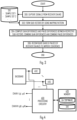
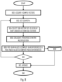
- the process comprises: capturing (block 300) a first signal from a first radio receiver chain and capturing a second signal from a second radio receiver chain; dividing (block 302) samples of the first signal into a first set of sub-vectors according to a determined mapping pattern that maps the samples of the first signal to sub-vectors of the first set; dividing (block 302) samples of the second signal into a second set of sub-vectors according to the determined mapping pattern; estimate (block 304) a gain difference and phase difference between each sub-vector of the first set and a respective sub-vector of the second set, thus acquiring sub-vector-level gain differences and sub-vector-level phase differences the first signal and the at least second signal; combining (block 304) the sub-vector level gain differences to acquire a gain difference between the first signal and the second signal, and combining the sub-vector-level phase differences to acquire a phase difference between the first signal and the second signal; and configuring (block 306) at least one of the first radio
- the process of Figure 3 may be used for uplink signals while the process of Figure 5 may be used for downlink signals.
- the first signal is acquired simultaneously with the second signal.
- the signals have thus experienced MIMO fading channel conditions in a radio channel.
- the embodiments described herein further improve performance against the MIMO fading, and improve accuracy of the gain and phase difference computation.
- the first signal and the second signal comprise payload data or signaling information to/from another apparatus.
- the process according to this embodiment operates 'blindly' and requires no separate pilot or reference signal transmissions, thus providing efficient operation and reduced signaling overhead.
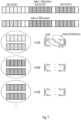
- Figure 7 illustrates the sub-vectorization and associated embodiment for blocks 302 and 304.
- the sample vectors (signal 1, ..., signal N) are illustrated as a sequence of samples (each sample represented by a small rectangle).
- the sub-vectors are illustrated by a sequence of samples having the same pattern (dotted or lined).
- An arbitrary number of sub-vectors may be taken from each sample vector, and the samples of the sub-vectors from a sample vector may be exclusive such that no sample of a sample vector is in multiple sub-vectors, or some samples may be in multiple sub-vectors but so that there are no two identical sub-vectors from a sample vector.
- H represents a Hermitian (conjugate transpose) operation.
- the cross-chain operation matrix resulting from this matrix multiplication operation will have a number of rows and a number of columns equal to the number of radio chains, e.g. 2-by-2 matrix in this case.
- the diagonal elements g 11 , g 22 of the cross-chain matrix COV represent gains introduced by the chains to the respective first radio chain's signal, actually magnitude-squared gains, while the other elements represent the phase differences between the chains ( ⁇ 12 representing the phase difference between chain 1 and chain 2).
- a set of gain difference values g 12 and a set of phase difference values ⁇ 12 is obtained.
- the number of sets of gain difference values g 12 and a set of phase difference values ⁇ 12 depend on the number of radio chains included in the process, and is N.
- the final estimate of the gain difference is achieved by averaging over the set of gain difference values g 12 while the final estimate of the phase difference is achieved by averaging over the set of phase difference values ⁇ 12 .
- the first sample vector may have the same total number of samples as the second sample vector, wherein the samples of the first signal and the second signal are indexed, and wherein the mapping pattern maps said indices to the sub-vectors.
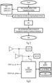
- the process may proceed to block 812 where the gain difference values are acquired from the database 820 and averaged. Similarly, the phase difference values are acquired from the database 820 and averaged. Thereafter, the process may proceed to the computation of the gain adjustment parameters and phase adjustment parameters for the chains.
- circuitry refers to one or more of the following: (a) hardware-only circuit implementations such as implementations in only analog and/or digital circuitry; (b) combinations of circuits and software and/or firmware, such as (as applicable): (i) a combination of processor(s) or processor cores; or (ii) portions of processor(s)/software including digital signal processor(s), software, and at least one memory that work together to cause an apparatus to perform specific functions; and (c) circuits, such as a microprocessor(s) or a portion of a microprocessor(s), that require software or firmware for operation, even if the software or firmware is not physically present.
- circuitry would also cover an implementation of merely a processor (or multiple processors) or portion of a processor, e.g. one core of a multi-core processor, and its (or their) accompanying software and/or firmware.
- circuitry would also cover, for example and if applicable to the particular element, a baseband integrated circuit, an application-specific integrated circuit (ASIC), and/or a field-programmable grid array (FPGA) circuit for the apparatus according to an embodiment of the invention.
- ASIC application-specific integrated circuit
- FPGA field-programmable grid array
- the processes or methods described in Figure 3 or any of the embodiments thereof may also be carried out in the form of one or more computer processes defined by one or more computer programs.
- the computer program(s) may be in source code form, object code form, or in some intermediate form, and it may be stored in some sort of carrier, which may be any entity or device capable of carrying the program.
- Such carriers include transitory and/or non-transitory computer media, e.g. a record medium, computer memory, read-only memory, electrical carrier signal, telecommunications signal, and software distribution package.
- the computer program may be executed in a single electronic digital processing unit or it may be distributed amongst a number of processing units.
- Embodiments described herein are applicable to wireless networks defined above but also to other wireless networks.
- the protocols used, the specifications of the wireless networks and their network elements develop rapidly. Such development may require extra changes to the described embodiments. Therefore, all words and expressions should be interpreted broadly and they are intended to illustrate, not to restrict, the embodiment. It will be obvious to a person skilled in the art that, as technology advances, the inventive concept can be implemented in various ways. Embodiments are not limited to the examples described above but may vary within the scope of the claims.
Landscapes
- Engineering & Computer Science (AREA)
- Computer Networks & Wireless Communication (AREA)
- Signal Processing (AREA)
- Radio Transmission System (AREA)
Claims (13)
- Einrichtung, die Mittel zum Durchführen von Folgendem umfasst:Erfassen (300) eines ersten Signals von einer ersten Funkkette;Teilen (302) von Proben des ersten Signals in einen ersten Satz von Untervektoren gemäß einem bestimmten Zuordnungsmuster, das die Proben des ersten Signals Untervektoren des ersten Satzes zuordnet;Erfassen (300) eines zweiten Signals von einer zweiten Funkkette, wobei die erste Funkkette und die zweite Funkkette entweder Funkempfängerketten oder Funksenderketten sind;Teilen (302) von Proben des zweiten Signals in einen zweiten Satz von Untervektoren gemäß dem bestimmten Zuordnungsmuster;Schätzen (304) einer Verstärkungsdifferenz und einer Phasendifferenz zwischen jedem Untervektor des ersten Satzes und einem jeweiligen Untervektor des zweiten Satzes, dadurch Erlangen von Untervektorebenenverstärkungsdifferenzen und Untervektorebenenphasendifferenzen des ersten Signals und des mindestens zweiten Signals;Kombinieren (304) der Untervektorebenenverstärkungsdifferenzen, um eine Verstärkungsdifferenz zwischen dem ersten Signal und dem zweiten Signal zu erlangen, und Kombinieren der Untervektorebenenphasendifferenzen, um eine Phasendifferenz zwischen dem ersten Signal und dem zweiten Signal zu erlangen; undAuslegen (306) von mindestens einer der ersten Funkkette und der zweiten Funkkette, um die Verstärkungsdifferenz und die Phasendifferenz zu reduzieren, und wobei die Einrichtung ferner eine Kopplungsschaltung umfasst, die zu Folgendem ausgelegt ist:
Koppeln der ersten Funkkette an die zweite Funkkette, um eine einzelne Funkkette zu bilden, und wobei die Mittel zu Folgendem ausgelegt sind:
Erlangen des ersten Signals und des zweiten Signals, während die erste Funkkette durch die Kopplungsschaltung an die zweite Funkkette gekoppelt ist. - Einrichtung nach Anspruch 1, wobei die erste Funkkette und die zweite Funkkette Funkempfängerketten sind, und wobei die Mittel dazu ausgelegt sind, das erste Signal und das zweite Signal nach einer Ausgabe eines Analog-Digital-Wandlers zu erfassen, der dazu ausgelegt ist, Analog-Digital-Umwandlungen des ersten Signals und des zweiten Signals durchzuführen.
- Einrichtung nach Anspruch 1 oder 2, wobei das Kombinieren das Mitteln der Untervektorebenenverstärkungsdifferenzen und das Mitteln der Untervektorebenenphasendifferenzen umfasst, um die Verstärkungsdifferenz und die Phasendifferenz zwischen dem ersten Signal bzw. dem zweiten Signal zu erhalten.
- Einrichtung nach Anspruch 3, wobei das erfasste erste Signal dieselbe Gesamtzahl von Proben aufweist wie das erfasste zweite Signal, wobei die Proben des ersten Signals und des zweiten Signals indexiert sind, und wobei das Zuordnungsmuster die Indices den Untervektoren zuordnet.
- Einrichtung nach einem der vorhergehenden Ansprüche, wobei die Mittel dazu ausgelegt sind, die Verstärkungsdifferenz und die Phasendifferenz durch Berechnen einer Hermitian-Multiplikation zwischen einer ersten Matrix, die Untervektoren des ersten Satzes umfasst, und einer zweiten Matrix, die jeweilige Untervektoren des zweiten Satzes umfasst, zu schätzen.
- Einrichtung nach einem der vorhergehenden Ansprüche, wobei die Mittel dazu ausgelegt sind, das erste Signal gleichzeitig mit dem zweiten Signal zu erlangen.
- Einrichtung nach einem der vorhergehenden Ansprüche, wobei das erste Signal und das zweite Signal Nutzdaten oder Signalisierungsinformationen von einer anderen Einrichtung umfassen.
- Einrichtung nach einem der vorhergehenden Ansprüche, wobei das erste Antennenelement und das zweite Antennenelement dazu ausgelegt sind, dieselbe Art einer Polarisierung zu empfangen.
- Einrichtung nach einem der vorhergehenden Ansprüche 1 bis 8, wobei die Mittel mindestens einen Prozessor und mindestens einen Speicher, der Computerprogrammcode beinhaltet, umfassen, wobei der mindestens eine Speicher und der Computerprogrammcode dazu ausgelegt sind, mit dem mindestens einen Prozessor die Durchführung der Einrichtung zu veranlassen.
- Einrichtung nach einem der vorhergehenden Ansprüche, wobei die Einrichtung für eine Endgerätevorrichtung eines zellularen Kommunikationssystems ist.
- Einrichtung nach einem der Ansprüche 1 bis 9, wobei die Einrichtung für einen Zugangsknoten eines zellularen Kommunikationssystems ist.
- Verfahren, das Folgendes umfasst:Erfassen (300) eines ersten Signals von einer ersten Funkkette;Teilen (302) von Proben des ersten Signals in einen ersten Satz von Untervektoren gemäß einem bestimmten Zuordnungsmuster, das die Proben des ersten Signals Untervektoren des ersten Satzes zuordnet;Erfassen (300) eines zweiten Signals von einer zweiten Funkkette, wobei die erste Funkkette und die zweite Funkkette entweder Funkempfängerketten oder Funksenderketten sind;Teilen (302) von Proben des zweiten Signals in einen zweiten Satz von Untervektoren gemäß dem bestimmten Zuordnungsmuster;Schätzen (304) einer Verstärkungsdifferenz und einer Phasendifferenz zwischen jedem Untervektor des ersten Satzes und einem jeweiligen Untervektor des zweiten Satzes, dadurch Erlangen von Untervektorebenenverstärkungsdifferenzen und Untervektorebenenphasendifferenzen des ersten Signals und des mindestens zweiten Signals;Kombinieren (304) der Untervektorebenenverstärkungsdifferenzen, um eine Verstärkungsdifferenz zwischen dem ersten Signal und dem zweiten Signal zu erlangen, und Kombinieren der Untervektorebenenphasendifferenzen, um eine Phasendifferenz zwischen dem ersten Signal und dem zweiten Signal zu erlangen; undAuslegen (306) von mindestens einer der ersten Funkkette und der zweiten Funkkette, um die Verstärkungsdifferenz und die Phasendifferenz zu reduzieren, und wobei das Verfahren ferner Folgendes umfasstKoppeln der ersten Funkkette durch eine Kopplungsschaltung an die zweite Funkkette, um eine einzelne Funkkette zu bilden; undErlangen des ersten Signals und des zweiten Signals, während die erste Funkkette durch die Kopplungsschaltung an die zweite Funkkette gekoppelt ist.
- Computerprogrammprodukt, das sich auf einem computerlesbaren Medium befindet und einen Computerprogrammcode umfasst, der von einem Computer lesbar ist, wobei der Computerprogrammcode den Computer dazu auslegt, einen Computerprozess umzusetzen, der Folgendes umfasst:Erfassen eines ersten Signals von einer ersten Funkkette;Teilen von Proben des ersten Signals in einen ersten Satz von Untervektoren gemäß einem bestimmten Zuordnungsmuster, das die Proben des ersten Signals Untervektoren des ersten Satzes zuordnet;Erfassen eines zweiten Signals von einer zweiten Funkkette, wobei die erste Funkkette und die zweite Funkkette entweder Funkempfängerketten oder Funksenderketten sind;Teilen von Proben des zweiten Signals in einen zweiten Satz von Untervektoren gemäß dem bestimmten Zuordnungsmuster;Schätzen einer Verstärkungsdifferenz und einer Phasendifferenz zwischen jedem Untervektor des ersten Satzes und einem jeweiligen Untervektor des zweiten Satzes, dadurch Erlangen von Untervektorebenenverstärkungsdifferenzen und Untervektorebenenphasendifferenzen des ersten Signals und des mindestens zweiten Signals;Kombinieren der Untervektorebenenverstärkungsdifferenzen, um eine Verstärkungsdifferenz zwischen dem ersten Signal und dem zweiten Signal zu erlangen, und Kombinieren der Untervektorebenenphasendifferenzen, um eine Phasendifferenz zwischen dem ersten Signal und dem zweiten Signal zu erlangen; undAuslegen von mindestens einer der ersten Funkkette und der zweiten Funkkette, um die Verstärkungsdifferenz und die Phasendifferenz zu reduzieren, und wobei das Verfahren ferner Folgendes umfasstKoppeln der ersten Funkkette durch eine Kopplungsschaltung an die zweite Funkkette, um eine einzelne Funkkette zu bilden; undErlangen des ersten Signals und des zweiten Signals, während die erste Funkkette durch die Kopplungsschaltung an die zweite Funkkette gekoppelt ist.
Applications Claiming Priority (1)
| Application Number | Priority Date | Filing Date | Title |
|---|---|---|---|
| FI20225360 | 2022-04-28 |
Publications (2)
| Publication Number | Publication Date |
|---|---|
| EP4270795A1 EP4270795A1 (de) | 2023-11-01 |
| EP4270795B1 true EP4270795B1 (de) | 2025-03-12 |
Family
ID=85222093
Family Applications (1)
| Application Number | Title | Priority Date | Filing Date |
|---|---|---|---|
| EP23155719.0A Active EP4270795B1 (de) | 2022-04-28 | 2023-02-09 | Schätzung und reduzierung des hf-kettenversatzes |
Country Status (3)
| Country | Link |
|---|---|
| US (1) | US11916586B2 (de) |
| EP (1) | EP4270795B1 (de) |
| CN (1) | CN116980264A (de) |
Family Cites Families (18)
| Publication number | Priority date | Publication date | Assignee | Title |
|---|---|---|---|---|
| US6570527B1 (en) | 2001-09-28 | 2003-05-27 | Arraycomm, Inc. | Calibration of differential frequency-dependent characteristics of a radio communications system |
| US7031669B2 (en) * | 2002-09-10 | 2006-04-18 | Cognio, Inc. | Techniques for correcting for phase and amplitude offsets in a MIMO radio device |
| US8654885B2 (en) * | 2006-06-06 | 2014-02-18 | Qualcomm Incorporated | Fast in-phase and quadrature imbalance calibration |
| US8374297B2 (en) * | 2008-09-15 | 2013-02-12 | Intel Corporation | Circuit, controller and methods for dynamic estimation and cancellation of phase and gain imbalances in quadrature signal paths of a receiver |
| EP2384558B1 (de) | 2009-01-30 | 2017-12-13 | Telefonaktiebolaget LM Ericsson (publ) | Phasenkalibration und detektion fehlerhafter verkabelung für eine mehrantennen-funkbasisstation |
| US8331493B2 (en) * | 2010-09-03 | 2012-12-11 | Nokia Corporation | Bias removal of radio link quality estimates |
| US8774738B2 (en) * | 2011-04-22 | 2014-07-08 | Broadcom Corporation | Closed loop power control for a wireless transmitter |
| US8891668B2 (en) * | 2011-06-30 | 2014-11-18 | Intel IP Corporation | System and method for estimating and correcting phase shift in a wireless communication device |
| US8737929B2 (en) * | 2012-06-27 | 2014-05-27 | Intel Corporation | Device, system and method of estimating a phase between radio-frequency chains |
| CN104993827B (zh) * | 2015-07-08 | 2018-03-02 | 中国电子科技集团公司第二十四研究所 | 模数转换器误差估计校正的装置及其方法 |
| US10103825B2 (en) | 2016-03-31 | 2018-10-16 | Spreadtrum Communications Usa Inc. | Transceiver system supporting receiver self calibration and methods of performing the same |
| US9774363B1 (en) * | 2016-07-01 | 2017-09-26 | Intel Corporation | Gain calibration for digitally controlled oscillator in fast locking phase locked loops |
| US9979458B1 (en) * | 2016-11-18 | 2018-05-22 | Nokia Solutions And Networks Oy | Precoder design for combining high-end RF with constrained RF of massive MIMO antennas |
| WO2020244783A1 (en) | 2019-06-07 | 2020-12-10 | Telefonaktiebolaget Lm Ericsson (Publ) | Calibration for antenna elements of a multi-antenna structure |
| US10484038B1 (en) * | 2019-06-27 | 2019-11-19 | Psemi Corporation | Phased array transceiver with built-in phase interferometer |
| US11637640B2 (en) | 2019-09-26 | 2023-04-25 | Apple Inc. | Self-calibration for implicit beamforming |
| US11322837B2 (en) | 2019-11-27 | 2022-05-03 | Infineon Technologies Ag | Calibration of active phased array system using beamforming RFIC built-in-test equipment |
| US10931362B1 (en) * | 2020-05-06 | 2021-02-23 | Tarana Wireless, Inc. | Interference resistant method for in-situ operational calibration and compensation of gain and phase variations in antenna array receiver RF and analog front-end electronics |
-
2023
- 2023-02-09 EP EP23155719.0A patent/EP4270795B1/de active Active
- 2023-03-16 US US18/122,418 patent/US11916586B2/en active Active
- 2023-03-29 CN CN202310321886.9A patent/CN116980264A/zh active Pending
Also Published As
| Publication number | Publication date |
|---|---|
| US20230353183A1 (en) | 2023-11-02 |
| CN116980264A (zh) | 2023-10-31 |
| US11916586B2 (en) | 2024-02-27 |
| EP4270795A1 (de) | 2023-11-01 |
Similar Documents
| Publication | Publication Date | Title |
|---|---|---|
| EP4235209B1 (de) | Bestimmung der übertragungsleistung pro strahlpaar bei gemeinsamer kommunikation und erkennung | |
| US12308926B2 (en) | Apparatus for selecting radio beams | |
| US12273161B2 (en) | Estimating a link budget | |
| US20230352838A1 (en) | Beam alignment in an apparatus | |
| US11800514B2 (en) | Configuration for uplink signals over fronthaul interface | |
| US11664867B2 (en) | Computation of beamforming parameters | |
| US11057063B1 (en) | Dual-band digital pre-distortion | |
| US20230370022A1 (en) | Energy efficient amplification for an apparatus | |
| EP4270795B1 (de) | Schätzung und reduzierung des hf-kettenversatzes | |
| CN112636854A (zh) | 测量mimo收发器中的延迟 | |
| WO2019222913A1 (en) | Transmission method | |
| US10797930B1 (en) | Apparatus and method for detection of received signals | |
| US12170558B2 (en) | Obtaining location information | |
| US12199707B2 (en) | MIMO antennas | |
| US20250379622A1 (en) | Wideband beamforming for mimo systems | |
| US11552661B2 (en) | Interference detection in radio access network | |
| US20240204891A1 (en) | Interference rejection in cooperative multi-point communication | |
| US12170585B2 (en) | Processing signals | |
| US20240073723A1 (en) | Test methodology for integrated access and backhaul | |
| US20250175964A1 (en) | Co-phasing beams | |
| US20220394534A1 (en) | Apparatus for receiving a measurement |
Legal Events
| Date | Code | Title | Description |
|---|---|---|---|
| PUAI | Public reference made under article 153(3) epc to a published international application that has entered the european phase |
Free format text: ORIGINAL CODE: 0009012 |
|
| STAA | Information on the status of an ep patent application or granted ep patent |
Free format text: STATUS: THE APPLICATION HAS BEEN PUBLISHED |
|
| AK | Designated contracting states |
Kind code of ref document: A1 Designated state(s): AL AT BE BG CH CY CZ DE DK EE ES FI FR GB GR HR HU IE IS IT LI LT LU LV MC ME MK MT NL NO PL PT RO RS SE SI SK SM TR |
|
| STAA | Information on the status of an ep patent application or granted ep patent |
Free format text: STATUS: REQUEST FOR EXAMINATION WAS MADE |
|
| 17P | Request for examination filed |
Effective date: 20240502 |
|
| RBV | Designated contracting states (corrected) |
Designated state(s): AL AT BE BG CH CY CZ DE DK EE ES FI FR GB GR HR HU IE IS IT LI LT LU LV MC ME MK MT NL NO PL PT RO RS SE SI SK SM TR |
|
| GRAP | Despatch of communication of intention to grant a patent |
Free format text: ORIGINAL CODE: EPIDOSNIGR1 |
|
| STAA | Information on the status of an ep patent application or granted ep patent |
Free format text: STATUS: GRANT OF PATENT IS INTENDED |
|
| RIC1 | Information provided on ipc code assigned before grant |
Ipc: H04B 7/04 20170101ALI20240919BHEP Ipc: H04B 1/04 20060101ALI20240919BHEP Ipc: H04B 1/00 20060101AFI20240919BHEP |
|
| INTG | Intention to grant announced |
Effective date: 20241004 |
|
| GRAS | Grant fee paid |
Free format text: ORIGINAL CODE: EPIDOSNIGR3 |
|
| GRAA | (expected) grant |
Free format text: ORIGINAL CODE: 0009210 |
|
| STAA | Information on the status of an ep patent application or granted ep patent |
Free format text: STATUS: THE PATENT HAS BEEN GRANTED |
|
| AK | Designated contracting states |
Kind code of ref document: B1 Designated state(s): AL AT BE BG CH CY CZ DE DK EE ES FI FR GB GR HR HU IE IS IT LI LT LU LV MC ME MK MT NL NO PL PT RO RS SE SI SK SM TR |
|
| REG | Reference to a national code |
Ref country code: GB Ref legal event code: FG4D |
|
| REG | Reference to a national code |
Ref country code: CH Ref legal event code: EP |
|
| REG | Reference to a national code |
Ref country code: DE Ref legal event code: R096 Ref document number: 602023002337 Country of ref document: DE |
|
| REG | Reference to a national code |
Ref country code: IE Ref legal event code: FG4D |
|
| PG25 | Lapsed in a contracting state [announced via postgrant information from national office to epo] |
Ref country code: RS Free format text: LAPSE BECAUSE OF FAILURE TO SUBMIT A TRANSLATION OF THE DESCRIPTION OR TO PAY THE FEE WITHIN THE PRESCRIBED TIME-LIMIT Effective date: 20250612 |
|
| PG25 | Lapsed in a contracting state [announced via postgrant information from national office to epo] |
Ref country code: FI Free format text: LAPSE BECAUSE OF FAILURE TO SUBMIT A TRANSLATION OF THE DESCRIPTION OR TO PAY THE FEE WITHIN THE PRESCRIBED TIME-LIMIT Effective date: 20250312 |
|
| PG25 | Lapsed in a contracting state [announced via postgrant information from national office to epo] |
Ref country code: ES Free format text: LAPSE BECAUSE OF FAILURE TO SUBMIT A TRANSLATION OF THE DESCRIPTION OR TO PAY THE FEE WITHIN THE PRESCRIBED TIME-LIMIT Effective date: 20250312 |
|
| REG | Reference to a national code |
Ref country code: LT Ref legal event code: MG9D |
|
| PG25 | Lapsed in a contracting state [announced via postgrant information from national office to epo] |
Ref country code: NO Free format text: LAPSE BECAUSE OF FAILURE TO SUBMIT A TRANSLATION OF THE DESCRIPTION OR TO PAY THE FEE WITHIN THE PRESCRIBED TIME-LIMIT Effective date: 20250612 |
|
| PG25 | Lapsed in a contracting state [announced via postgrant information from national office to epo] |
Ref country code: HR Free format text: LAPSE BECAUSE OF FAILURE TO SUBMIT A TRANSLATION OF THE DESCRIPTION OR TO PAY THE FEE WITHIN THE PRESCRIBED TIME-LIMIT Effective date: 20250312 |
|
| REG | Reference to a national code |
Ref country code: NL Ref legal event code: MP Effective date: 20250312 |
|
| PG25 | Lapsed in a contracting state [announced via postgrant information from national office to epo] |
Ref country code: LV Free format text: LAPSE BECAUSE OF FAILURE TO SUBMIT A TRANSLATION OF THE DESCRIPTION OR TO PAY THE FEE WITHIN THE PRESCRIBED TIME-LIMIT Effective date: 20250312 |
|
| PG25 | Lapsed in a contracting state [announced via postgrant information from national office to epo] |
Ref country code: GR Free format text: LAPSE BECAUSE OF FAILURE TO SUBMIT A TRANSLATION OF THE DESCRIPTION OR TO PAY THE FEE WITHIN THE PRESCRIBED TIME-LIMIT Effective date: 20250613 Ref country code: BG Free format text: LAPSE BECAUSE OF FAILURE TO SUBMIT A TRANSLATION OF THE DESCRIPTION OR TO PAY THE FEE WITHIN THE PRESCRIBED TIME-LIMIT Effective date: 20250312 |
|
| REG | Reference to a national code |
Ref country code: AT Ref legal event code: MK05 Ref document number: 1775892 Country of ref document: AT Kind code of ref document: T Effective date: 20250312 |
|
| PG25 | Lapsed in a contracting state [announced via postgrant information from national office to epo] |
Ref country code: NL Free format text: LAPSE BECAUSE OF FAILURE TO SUBMIT A TRANSLATION OF THE DESCRIPTION OR TO PAY THE FEE WITHIN THE PRESCRIBED TIME-LIMIT Effective date: 20250312 |
|
| PG25 | Lapsed in a contracting state [announced via postgrant information from national office to epo] |
Ref country code: SE Free format text: LAPSE BECAUSE OF FAILURE TO SUBMIT A TRANSLATION OF THE DESCRIPTION OR TO PAY THE FEE WITHIN THE PRESCRIBED TIME-LIMIT Effective date: 20250312 |
|
| PG25 | Lapsed in a contracting state [announced via postgrant information from national office to epo] |
Ref country code: SM Free format text: LAPSE BECAUSE OF FAILURE TO SUBMIT A TRANSLATION OF THE DESCRIPTION OR TO PAY THE FEE WITHIN THE PRESCRIBED TIME-LIMIT Effective date: 20250312 |
|
| PG25 | Lapsed in a contracting state [announced via postgrant information from national office to epo] |
Ref country code: PT Free format text: LAPSE BECAUSE OF FAILURE TO SUBMIT A TRANSLATION OF THE DESCRIPTION OR TO PAY THE FEE WITHIN THE PRESCRIBED TIME-LIMIT Effective date: 20250714 |
|
| PG25 | Lapsed in a contracting state [announced via postgrant information from national office to epo] |
Ref country code: PL Free format text: LAPSE BECAUSE OF FAILURE TO SUBMIT A TRANSLATION OF THE DESCRIPTION OR TO PAY THE FEE WITHIN THE PRESCRIBED TIME-LIMIT Effective date: 20250312 Ref country code: IT Free format text: LAPSE BECAUSE OF FAILURE TO SUBMIT A TRANSLATION OF THE DESCRIPTION OR TO PAY THE FEE WITHIN THE PRESCRIBED TIME-LIMIT Effective date: 20250312 |
|
| PG25 | Lapsed in a contracting state [announced via postgrant information from national office to epo] |
Ref country code: AT Free format text: LAPSE BECAUSE OF FAILURE TO SUBMIT A TRANSLATION OF THE DESCRIPTION OR TO PAY THE FEE WITHIN THE PRESCRIBED TIME-LIMIT Effective date: 20250312 |
|
| PG25 | Lapsed in a contracting state [announced via postgrant information from national office to epo] |
Ref country code: CZ Free format text: LAPSE BECAUSE OF FAILURE TO SUBMIT A TRANSLATION OF THE DESCRIPTION OR TO PAY THE FEE WITHIN THE PRESCRIBED TIME-LIMIT Effective date: 20250312 Ref country code: EE Free format text: LAPSE BECAUSE OF FAILURE TO SUBMIT A TRANSLATION OF THE DESCRIPTION OR TO PAY THE FEE WITHIN THE PRESCRIBED TIME-LIMIT Effective date: 20250312 |
|
| PG25 | Lapsed in a contracting state [announced via postgrant information from national office to epo] |
Ref country code: RO Free format text: LAPSE BECAUSE OF FAILURE TO SUBMIT A TRANSLATION OF THE DESCRIPTION OR TO PAY THE FEE WITHIN THE PRESCRIBED TIME-LIMIT Effective date: 20250312 |
|
| PG25 | Lapsed in a contracting state [announced via postgrant information from national office to epo] |
Ref country code: SK Free format text: LAPSE BECAUSE OF FAILURE TO SUBMIT A TRANSLATION OF THE DESCRIPTION OR TO PAY THE FEE WITHIN THE PRESCRIBED TIME-LIMIT Effective date: 20250312 |
|
| PG25 | Lapsed in a contracting state [announced via postgrant information from national office to epo] |
Ref country code: IS Free format text: LAPSE BECAUSE OF FAILURE TO SUBMIT A TRANSLATION OF THE DESCRIPTION OR TO PAY THE FEE WITHIN THE PRESCRIBED TIME-LIMIT Effective date: 20250712 |
|
| REG | Reference to a national code |
Ref country code: DE Ref legal event code: R097 Ref document number: 602023002337 Country of ref document: DE |
|
| PG25 | Lapsed in a contracting state [announced via postgrant information from national office to epo] |
Ref country code: DK Free format text: LAPSE BECAUSE OF FAILURE TO SUBMIT A TRANSLATION OF THE DESCRIPTION OR TO PAY THE FEE WITHIN THE PRESCRIBED TIME-LIMIT Effective date: 20250312 |
|
| PLBE | No opposition filed within time limit |
Free format text: ORIGINAL CODE: 0009261 |
|
| STAA | Information on the status of an ep patent application or granted ep patent |
Free format text: STATUS: NO OPPOSITION FILED WITHIN TIME LIMIT |
|
| REG | Reference to a national code |
Ref country code: CH Ref legal event code: L10 Free format text: ST27 STATUS EVENT CODE: U-0-0-L10-L00 (AS PROVIDED BY THE NATIONAL OFFICE) Effective date: 20260121 |