EP3324494A1 - Connector - Google Patents
Connector Download PDFInfo
- Publication number
- EP3324494A1 EP3324494A1 EP16824249.3A EP16824249A EP3324494A1 EP 3324494 A1 EP3324494 A1 EP 3324494A1 EP 16824249 A EP16824249 A EP 16824249A EP 3324494 A1 EP3324494 A1 EP 3324494A1
- Authority
- EP
- European Patent Office
- Prior art keywords
- lock
- retainer
- protrusion
- housing
- full locking
- Prior art date
- Legal status (The legal status is an assumption and is not a legal conclusion. Google has not performed a legal analysis and makes no representation as to the accuracy of the status listed.)
- Granted
Links
Images


Classifications
-
- H—ELECTRICITY
- H01—ELECTRIC ELEMENTS
- H01R—ELECTRICALLY-CONDUCTIVE CONNECTIONS; STRUCTURAL ASSOCIATIONS OF A PLURALITY OF MUTUALLY-INSULATED ELECTRICAL CONNECTING ELEMENTS; COUPLING DEVICES; CURRENT COLLECTORS
- H01R13/00—Details of coupling devices of the kinds covered by groups H01R12/70 or H01R24/00 - H01R33/00
- H01R13/40—Securing contact members in or to a base or case; Insulating of contact members
- H01R13/42—Securing in a demountable manner
- H01R13/436—Securing a plurality of contact members by one locking piece or operation
- H01R13/4367—Insertion of locking piece from the rear
- H01R13/4368—Insertion of locking piece from the rear comprising a temporary and a final locking position
-
- H—ELECTRICITY
- H01—ELECTRIC ELEMENTS
- H01R—ELECTRICALLY-CONDUCTIVE CONNECTIONS; STRUCTURAL ASSOCIATIONS OF A PLURALITY OF MUTUALLY-INSULATED ELECTRICAL CONNECTING ELEMENTS; COUPLING DEVICES; CURRENT COLLECTORS
- H01R13/00—Details of coupling devices of the kinds covered by groups H01R12/70 or H01R24/00 - H01R33/00
- H01R13/40—Securing contact members in or to a base or case; Insulating of contact members
- H01R13/42—Securing in a demountable manner
- H01R13/424—Securing in base or case composed of a plurality of insulating parts having at least one resilient insulating part
-
- H—ELECTRICITY
- H01—ELECTRIC ELEMENTS
- H01R—ELECTRICALLY-CONDUCTIVE CONNECTIONS; STRUCTURAL ASSOCIATIONS OF A PLURALITY OF MUTUALLY-INSULATED ELECTRICAL CONNECTING ELEMENTS; COUPLING DEVICES; CURRENT COLLECTORS
- H01R13/00—Details of coupling devices of the kinds covered by groups H01R12/70 or H01R24/00 - H01R33/00
- H01R13/40—Securing contact members in or to a base or case; Insulating of contact members
- H01R13/42—Securing in a demountable manner
- H01R13/436—Securing a plurality of contact members by one locking piece or operation
- H01R13/4361—Insertion of locking piece perpendicular to direction of contact insertion
- H01R13/4362—Insertion of locking piece perpendicular to direction of contact insertion comprising a temporary and a final locking position
-
- H—ELECTRICITY
- H01—ELECTRIC ELEMENTS
- H01R—ELECTRICALLY-CONDUCTIVE CONNECTIONS; STRUCTURAL ASSOCIATIONS OF A PLURALITY OF MUTUALLY-INSULATED ELECTRICAL CONNECTING ELEMENTS; COUPLING DEVICES; CURRENT COLLECTORS
- H01R13/00—Details of coupling devices of the kinds covered by groups H01R12/70 or H01R24/00 - H01R33/00
- H01R13/46—Bases; Cases
- H01R13/502—Bases; Cases composed of different pieces
- H01R13/5025—Bases; Cases composed of different pieces one or more pieces being of resilient material
-
- H—ELECTRICITY
- H01—ELECTRIC ELEMENTS
- H01R—ELECTRICALLY-CONDUCTIVE CONNECTIONS; STRUCTURAL ASSOCIATIONS OF A PLURALITY OF MUTUALLY-INSULATED ELECTRICAL CONNECTING ELEMENTS; COUPLING DEVICES; CURRENT COLLECTORS
- H01R13/00—Details of coupling devices of the kinds covered by groups H01R12/70 or H01R24/00 - H01R33/00
- H01R13/46—Bases; Cases
- H01R13/52—Dustproof, splashproof, drip-proof, waterproof, or flameproof cases
- H01R13/5205—Sealing means between cable and housing, e.g. grommet
-
- H—ELECTRICITY
- H01—ELECTRIC ELEMENTS
- H01R—ELECTRICALLY-CONDUCTIVE CONNECTIONS; STRUCTURAL ASSOCIATIONS OF A PLURALITY OF MUTUALLY-INSULATED ELECTRICAL CONNECTING ELEMENTS; COUPLING DEVICES; CURRENT COLLECTORS
- H01R43/00—Apparatus or processes specially adapted for manufacturing, assembling, maintaining, or repairing of line connectors or current collectors or for joining electric conductors
- H01R43/18—Apparatus or processes specially adapted for manufacturing, assembling, maintaining, or repairing of line connectors or current collectors or for joining electric conductors for manufacturing bases or cases for contact members
-
- H—ELECTRICITY
- H01—ELECTRIC ELEMENTS
- H01R—ELECTRICALLY-CONDUCTIVE CONNECTIONS; STRUCTURAL ASSOCIATIONS OF A PLURALITY OF MUTUALLY-INSULATED ELECTRICAL CONNECTING ELEMENTS; COUPLING DEVICES; CURRENT COLLECTORS
- H01R13/00—Details of coupling devices of the kinds covered by groups H01R12/70 or H01R24/00 - H01R33/00
- H01R13/40—Securing contact members in or to a base or case; Insulating of contact members
- H01R13/42—Securing in a demountable manner
- H01R13/422—Securing in resilient one-piece base or case, e.g. by friction; One-piece base or case formed with resilient locking means
- H01R13/4223—Securing in resilient one-piece base or case, e.g. by friction; One-piece base or case formed with resilient locking means comprising integral flexible contact retaining fingers
-
- H—ELECTRICITY
- H01—ELECTRIC ELEMENTS
- H01R—ELECTRICALLY-CONDUCTIVE CONNECTIONS; STRUCTURAL ASSOCIATIONS OF A PLURALITY OF MUTUALLY-INSULATED ELECTRICAL CONNECTING ELEMENTS; COUPLING DEVICES; CURRENT COLLECTORS
- H01R13/00—Details of coupling devices of the kinds covered by groups H01R12/70 or H01R24/00 - H01R33/00
- H01R13/66—Structural association with built-in electrical component
- H01R13/70—Structural association with built-in electrical component with built-in switch
- H01R13/703—Structural association with built-in electrical component with built-in switch operated by engagement or disengagement of coupling parts, e.g. dual-continuity coupling part
- H01R13/7031—Shorting, shunting or bussing of different terminals interrupted or effected on engagement of coupling part, e.g. for ESD protection, line continuity
Landscapes
- Engineering & Computer Science (AREA)
- Manufacturing & Machinery (AREA)
- Connector Housings Or Holding Contact Members (AREA)
Abstract
Description
- The present invention relates to a connector.
- A connector disclosed in patent literature 1 includes a housing having a terminal accommodating portion (cavity) capable of accommodating a female terminal (terminal fitting) and a locking member (retainer) to be inserted into a locking member accommodation hole (mounting hole) of the housing and having a doubly locking portion (retaining portion) for locking the female terminal in the terminal accommodating portion in a retained state. Engaging holes (lock receiving portions) communicating with the locking member accommodation hole are provided in both side surfaces of the housing. Engaging projections (locks) insertable into the engaging holes (lock receiving portions) for locking are provided on both side surfaces of the locking member.
- The locking member accommodation hole has a rectangular cross-section and is shaped to communicate with the terminal accommodating portion and be open in the upper surface of the housing. The housing includes thin side walls for closing the locking member accommodation hole from opposite sides. The side walls are deflected and deformed by the engaging projections sliding on the inner surfaces thereof in the process of mounting the locking member into the locking member accommodation hole, and the deflected state is released and the engaging projections are inserted into the engaging hole as the engaging projections reach positions corresponding to the engaging holes.
- Patent Literature 1:
Japanese Unexamined Patent Publication No.2002-231367 - The above engaging projection is shaped such that both end corner parts in a sliding width direction perpendicular to a sliding direction on the side wall are right-angled. Thus, as shown as a reference in
FIG. 12 , in the sliding process of anengaging projection 2 on aside wall 3, theside wall 3 is strongly pulled by bothend corner parts 4 of theengaging projection 2 and, in a worst case scenario, theside wall 3 may be deflected beyond a resiliency limit to be broken. - The present invention was completed based on the above situation and aims to provide a connector capable of preventing the breakage of side walls.
- The present invention is directed to a connector with a housing including a cavity into which a terminal fitting is insertable, a mounting hole communicating with the cavity, deflectable side walls for closing the mounting hole from opposite sides, and lock receiving portions provided on the side walls, and a retainer to be inserted into the mounting hole and including a retaining portion for locking the terminal fitting in the cavity and lock protrusions lockable to the housing by coming into contact with the lock receiving portions and provided at positions where the lock protrusions are slidable on the side walls on outer sides, both end corner parts of the lock protrusion in a sliding width direction perpendicular to a sliding direction on the side wall being chamfered.
- Since the both end corner parts of the lock protrusion in the sliding width direction are chamfered, it can be suppressed that the side wall is deflected and deformed and strongly pulled by the lock protrusion and the breakage of the side wall can be prevented when the lock protrusion slides.
-
-
FIG. 1 is a front view in section of a housing, in which a retainer is held at a partial locking position, in a connector of an embodiment of the present invention, -
FIG. 2 is a front view in section of the housing in which the retainer is held at a full locking position, -
FIG. 3 is a side view in section of the housing in which the retainer is held at the partial locking position, -
FIG. 4 is a side view in section of the housing in which the retainer is held at the full locking position, -
FIG. 5 is a side view of the housing in which the retainer is held at the partial locking position, -
FIG. 6 is a side view of the housing in which the retainer is held at the full locking position, -
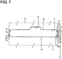
FIG. 7 is a bottom view of the housing having side walls deflected and deformed by lock protrusions in the process of moving the retainer toward the partial locking position, -
FIG. 8 is a front view of the retainer, -
FIG. 9 is a plan view of the retainer, -
FIG. 10 is a side view of the retainer, -
FIG. 11 is a bottom view of the housing, and -
FIG. 12 is a view showing a problem residing in a prior art. - Preferred embodiments of the present invention are described below.
- A tip corner part of the lock protrusion in the sliding direction on the side wall is chamfered. According to this configuration, it can be more suppressed that the side wall is strongly pulled by the lock protrusion and the breakage of the side wall can be more reliably prevented when the lock protrusion slides while deflecting the side wall.
- A dimension of a base of the lock protrusion in the sliding width direction is equal to or larger than half the opening dimension of the mounting hole in the sliding width direction. According to this configuration, since the side wall is easily broken by being pulled by the lock protrusion, it provides a large advantage that the both end corner parts of the lock protrusion in the sliding width direction are chamfered.
- A projecting end of the lock protrusion is arranged to be retracted from an outer surface of the side wall with the lock protrusion inserted in the lock receiving portion. According to this configuration, the interference of external matters with the projecting end of the lock protrusion can be avoided with the lock protrusion inserted in the lock receiving portion.
- The retainer is movable, with respect to the housing, to a partial locking position where the retaining portion is retracted from the cavity and a full locking position where the retaining portion is inserted into the cavity to retain the terminal fitting, and provided with full locking protrusions separately from the lock protrusions, the lock protrusions lock the lock receiving portions to restrict the separation of the retainer from the housing at the partial locking position, and the full locking protrusions lock full locking receiving portions of the housing to restrict a returning movement of the retainer to the partial locking position at the full locking position, and the full locking protrusion is arranged in front of the lock protrusion in the sliding direction of the lock protrusion on the side wall. According to this configuration, a range in which the lock protrusion slides on the side wall can be reduced and the breakage of the side wall can be even more reliably prevented.
- A projecting dimension of the full locking protrusion is smaller than that of the lock protrusion. According to this configuration, sliding resistance between the full locking protrusion and the side wall can be reduced and the breakage of the side wall by the full locking protrusion can be prevented in the process of moving the retainer to the full locking position.
- Hereinafter, an embodiment of the present invention is described on the basis of the drawings. A connector of this embodiment includes, as shown in
FIGS. 3 and4 , ahousing 10,terminal fittings 40 to be accommodated into thehousing 10 and aretainer 60 to be mounted into thehousing 10. Note that, in the following description, a left side ofFIGS. 3 to 6 ,9 and10 is referred to as a front side concerning a front-rear direction. Further, a vertical direction is based onFIGS. 1 to 6 ,8 and10 and a lateral direction is based onFIGS. 1 ,2 ,7 ,8 and11 . - The
housing 10 is made of synthetic resin and connectable to an unillustrated mating housing from front and includes ahousing body 11 substantially in the form of a rectangular block. As shown inFIGS. 3 and4 , a plurality ofcavities 12 are provided to penetrate through thehousing body 11 in the front-rear direction. Alocking lance 13 cantilevered forward is provided at an inner wall of eachcavity 12. Theterminal fitting 40 is inserted into thecavity 12 from behind. - The
terminal fitting 40 is made of an electrically conductive material and, as shown inFIGS. 3 and4 , formed to be long and narrow in the front-rear direction as a whole. Theterminal fitting 40 includes a tubular connectingportion 41 in a front part and abarrel portion 42 in the form of an open barrel in a rear part. A male tab of an unillustrated mating terminal fitting mounted in the mounting housing is inserted into the connectingportion 41 for connection when the both housings are properly connected. The connectingportion 41 is locked by thelocking lance 13. Thebarrel portion 42 is crimped and connected to an end part of awire 50. - As shown in
FIGS. 3 and4 , aterminal accommodation chamber 14 for accommodating ashorting terminal 55 is provided between thecavities 12 in an upper stage and thecavities 12 located therebelow in thehousing body 11. Although not shown in detail, the shortingterminal 55 is resiliently held in contact with theterminal fittings 40 adjacent in the lateral direction in thecavities 12 in the upper stage to maintain the bothterminal fittings 40 in a shorted state until the both housings are properly connected, and releases the shorted state of the bothterminal fittings 40 by being separated from the bothterminal fittings 40 when the both housings are properly connected. - As shown in
FIGS. 3 and4 , afront member 90 separate from thehousing body 11 is mounted on thehousing body 11. Thefront member 90 is made of synthetic resin and includes a plate-like front wall 91 fittable into arecess 15 provided in the front surface of thehousing body 11. Thefront wall 91 includes a plurality oftab insertion holes 92 allowing the passage of the mating tabs of the mating terminal fittings at positions corresponding to therespective cavities 12 and theterminal accommodation chamber 14. Note that a front end part of the connectingportion 41 is fit and inserted into a rear end part of thetab insertion hole 92. - As shown in
FIGS. 1 to 4 , a flatlever accommodation chamber 16 penetrating in the front-rear direction is provided in an upper end part of thehousing body 11. An unillustrated lever is rotatably accommodated into thelever accommodation chamber 16. - As shown in
FIG. 11 , a mountinghole 17 having a substantially rectangular shape long in the lateral direction is provided to be open in the lower surface of thehousing body 11. The mountinghole 17 communicates with all thecavities 12 at a position behind the locking lances 13 and, as shown inFIGS. 1 and2 , has both left and right sides closed by a pair ofside walls 18 and an upper side closed by anupper wall 19. Theretainer 60 is inserted into the mountinghole 17 from below. Theupper wall 19 is arranged along the lateral direction and functions as a wall for partitioning between thelever accommodation chamber 16 and the mountinghole 17. - The both
side walls 18 are thinner than theupper wall 19 as a whole and deflectable and deformable in directions to protrude outward with parts coupled to front and rear areas across the mountinghole 17 in thehousing body 11 as supporting points as shown inFIG. 7 . - As shown in
FIG. 11 , a shallowfitting recess 21 is provided at a position in front of and communicating with the mountinghole 17 in the lower surface of thehousing body 11. As shown inFIG. 7 , a projectingpiece 65 of theretainer 60 is fittable into thefitting recess 21. - As shown in
FIGS. 5 and6 ,lock receiving portions 22 extending in the front-rear direction are provided to be open in rear parts of the both side surfaces of thehousing body 11 and fulllocking receiving portions 23 extending in the front-rear direction in parallel to thelock receiving portions 22 are provided to be open above thelock receiving portions 22. Thelock receiving portions 22 and the fulllocking receiving portions 23 are both open in the rear end of thehousing body 11 and, as shown inFIGS. 1 and2 , penetrate through theside walls 18 in a thickness direction (lateral direction). - As shown in
FIGS. 5 and6 , a vertical opening width of thelock receiving portion 22 is larger than that of the fulllocking receiving portion 23. A later-described lock portion of theretainer 60 is insertable into thelock receiving portion 22 of theside wall 18 for locking as shown inFIG. 5 , and a later-describedfull locking protrusion 67 of theretainer 60 is insertable into the fulllocking receiving portion 23 of theside wall 18 for locking as shown inFIG. 6 . - As shown in
FIGS. 1 and2 , an escapinggroove 24 extending from a position below the fulllocking receiving portion 23 to the lower surface of thehousing body 11 and communicating with thelock receiving portion 22 at an intermediate position is provided in the inner surface of theside wall 18. In the process of mounting theretainer 60 into thehousing 10, thefull locking protrusions 67 are inserted into the escapinggrooves 24 and allowed to escape. The upper surface of the escapinggroove 24 is formed into an upwardly inclined taperedsurface 25. Thefull locking protrusion 67 is slidable on the taperedsurface 25. - Next, the
retainer 60 is described. Theretainer 60 is made of synthetic resin and includes, as shown inFIGS. 8 to 10 , a plate-like retainer body 61 somewhat thick in the front-rear direction and long in the lateral direction. Theretainer body 61 of theretainer 60 is inserted into the mountinghole 17 from below and theretainer 60 is movable to a partial locking position (seeFIGS. 1 and3 ) where a lower end part of theretainer body 61 is arranged to project from the lower surface of thehousing body 11 and a full locking position (seeFIGS. 2 and4 ) where the lower end of theretainer body 61 is arranged substantially at the same height as the lower surface of thehousing body 11 by pushing and deeply inserting theretainer body 61 into the mountinghole 17 from the partial locking position. - The
retainer body 61 is provided with a plurality of throughholes 62 penetrating at positions communicating with therespective cavities 12 at the full locking position as shown inFIG. 8 . Each throughhole 62 has a substantially rectangular opening cross-section corresponding to a cross-sectional shape of the connectingportion 41 of theterminal fitting 40. A retainingportion 63 is provided to project on the lower edge of each throughhole 62. The retainingportions 63 are also provided onshoulder portions 64 slightly recessed on both left and right end parts of theretainer body 61 and on an upper end part in a substantially laterally central part of theretainer body 61. Theretainer 63 is arranged to be retracted downwardly of the correspondingcavity 12 from thecavity 12 at the partial locking position as shown inFIG. 3 and arranged to be lockable to the connectingportion 41 of the terminal fitting 40 by entering the correspondingcavity 12 at the full locking position as shown inFIG. 4 . - As shown in
FIGS. 8 and9 , the projectingpiece 65 is provided in a substantially laterally central part of the lower end of the front surface of theretainer body 61. The projectingpiece 65 is in the form of a thin plate extending along the lateral direction and fit and inserted into thefitting recess 21 of thehousing body 11 at the full locking position. Further, a rattling preventingrib 66 is provided in a substantially laterally central part of an upper part of the front surface of theretainer body 61. The rattling preventingrib 66 extends in the lateral direction in parallel to the projectingpiece 65. As shown inFIG. 4 , the rattling preventingrib 66 has a function of preventing the rattling of theterminal fittings 40 in the front-rear direction by coming into contact with theterminal fittings 40 to be connected to the aforementioned shortingterminal 55 at the full locking position. - As shown in
FIG. 8 , thefull locking protrusion 67 and alock protrusion 68 are provided side by side in the vertical direction on each of the both side surfaces of theretainer body 61. In the process of inserting theretainer body 61 into the mountinghole 17, thelock protrusions 68 slide on the inner surfaces of theside walls 18, specifically on groove surfaces of the escapinggrooves 24 of theside walls 18 and theside walls 18 are deflected and deformed to protrude outward. In the case of this embodiment, the vertical direction is an inserting direction of theretainer 60 into the mountinghole 17 and a sliding direction of the lock protrusions 68 on theside walls 18. Thus, in the following description, the vertical direction is referred to as a sliding direction X (seeFIGS. 1 ,2 ,5 ,6 ,8 and10 ), an upper side is referred to as a front side (leading side) in the sliding direction X and a lower side is referred to as a rear side in the sliding direction X if necessary. Further, the front-rear direction perpendicular to the sliding direction X is referred to as a sliding width direction Y (seeFIGS. 7 ,9 and10 ). - As shown in
FIG. 10 , thefull locking protrusion 67 is arranged above the lock protrusion 68 (on a front side in the inserting direction of theretainer 60 into the mounting hole 17) and in the form of a rib extending in the sliding width direction Y. As shown inFIG. 8 , the upper surface of thefull locking protrusion 67 is tapered downwardly toward a projecting end and the lower surface of thefull locking protrusion 67 is tapered upwardly toward the projecting end. Slit holes 69 long and narrow in the sliding direction X are provided at inner positions facing thefull locking protrusions 67 on both end parts of theretainer body 61. - As shown in
FIGS. 8 and9 , flat table-like base portions 71 are provided on lower parts of the both side surfaces of theretainer body 61. As shown inFIGS. 1 and2 , thebase portions 71 are fit and inserted into the escapinggrooves 24 with theretainer 60 inserted in the mountinghole 17. A projecting dimension (projecting dimension from the side surface of the retainer body 61) of thebase portion 71 is equal to or slightly smaller than that of thefull locking protrusion 67. - The
lock protrusion 68 projects from the outer surface of thebase portion 71 and is one size larger than thefull locking protrusion 67. As shown inFIG. 7 , a dimension of the base of thelock protrusion 68 in the sliding width direction Y is set to be equal to or larger than half the opening dimension of the mountinghole 17 in the sliding width direction Y. Further, a projecting dimension of thelock protrusion 68 is larger than that of thefull locking protrusion 67 and smaller than a depth of the lock receiving portion 22 (seeFIG. 1 ). - As shown in
FIG. 8 , the upper surface of thelock protrusion 68 is formed into a guidingsurface 72 tapered downwardly toward a projecting end. The lower surface of thelock protrusion 68 is formed into a substantiallyhorizontal locking surface 73 along the lateral direction. In other words, the guidingsurface 72 is formed by chamfering a tip corner part of thelock protrusion 68 in the sliding direction X in a tapered manner, and the lockingsurface 73 is shaped such that a rear end corner part of thelock protrusion 68 in the sliding direction X is at a right angle to the outer surface of thebase portion 71. - Further, as shown in
FIGS. 9 and10 , both front and rear surfaces (both end surfaces in the sliding width direction Y) of thelock protrusion 68 are formed into taperedinclined surfaces 74 inclined to approach each other toward the projecting end. In other words, theinclined surfaces 74 are shaped by chamfering both end corner parts of thelock protrusion 68 in the sliding width direction Y. An inclination angle of theinclined surface 74 with respect to the sliding width direction Y is a gentle inclination angle smaller than 45°. A dimension of thelock protrusion 68 in the sliding width direction Y is gradually reduced from the base toward the projecting end of thelock protrusion 68 by the both inclined surfaces 74. Further, as shown inFIG. 10 , a projectingend surface 75 of thelock protrusion 68 is defined by the guidingsurface 72, the lockingsurface 73 and the bothinclined surfaces 74 and has a flat rectangular shape long in the sliding width direction Y in a side view. - Next, functions of the connector of this embodiment are described. In assembling, the
retainer 60 is inserted into the mountinghole 17 of thehousing body 11 from below. When the insertion of theretainer 60 into the mountinghole 17 is started, the guiding surfaces 72 of thelock protrusions 68 slide on the inner surfaces of theside walls 18 and theside walls 18 are deflected and deformed to protrude outward. Further, in the process of inserting theretainer 60, the projecting end surfaces 75 of thelock protrusions 68 slide while pressing the inner surfaces of theside walls 18 and theside walls 18 are maximally deflected and deformed as shown inFIG. 7 . At this time,central parts 27 of theside walls 18 in the sliding width direction Y are arranged in contact with the projecting end surfaces 75 of thelock protrusions 68. On the other hand, bothend parts 28 of theside walls 18 in the sliding width direction Y are obliquely arranged between end edges 76 of the projecting end surfaces 75 of theside walls 18 and front and rear corner edges 77 of theretainer body 61 and arranged at a distance from theinclined surfaces 74 of thelock protrusions 68 without contacting the inclined surfaces 74. Thus, substantially no frictional resistance is generated between the bothend parts 28 of theside walls 18 in the sliding width direction Y and thelock protrusions 68 and theside walls 18 are satisfactorily deflected and deformed within the range of resiliency limit thereof. - Thereafter, when the
lock protrusions 68 reach positions corresponding to thelock receiving portions 22, theside walls 18 resiliently return and, as shown inFIGS. 1 and5 , thelock protrusions 68 are inserted into thelock receiving portions 22 and the locking surfaces 73 of thelock protrusions 68 are arranged to be able to come into contact with the lower ends of thelock receiving portions 22. Thus, downward separation of theretainer 60 from thehousing body 11 is prevented. Further, thefull locking protrusions 67 are arranged to be able to come into contact with the tapered surfaces 25 of the escapinggrooves 24, whereby an upward movement of theretainer 60 is restricted. In this way, theretainer 60 is held at the partial locking position with vertical movements restricted. Note that, as shown inFIG. 1 , the projecting end surfaces 75 of thelock protrusions 68 inserted into thelock receiving portions 22 are arranged at positions retracted from the outer surfaces of theside walls 18. - As shown in
FIG. 3 , when theretainer 60 is at the partial locking position, theterminal fittings 40 are inserted into thecavities 12 of thehousing body 11 from behind and the properly insertedterminal fittings 40 are temporarily retained by the locking lances 13. Subsequently, theretainer 60 is moved to the full locking position. In the process of moving theretainer 60 to the full locking position, thefull locking protrusions 67 slide on the tapered surfaces 25 of the escapinggrooves 24 and are resiliently displaced inwardly while narrowing the slit holes 69. Further, in the process of moving theretainer 60 toward the full locking position, thelock protrusions 68 move upward in thelock receiving portions 22 and are kept in a state not in contact with theside walls 18. - When the
retainer 60 reaches the full locking position, the slit holes 69 are restored to have an initial hole width and, as shown inFIGS. 2 and6 , thefull locking protrusions 67 are inserted into the fulllocking receiving portions 23 and arranged to be lockable to the lower ends of the fulllocking receiving portions 23. Further, at the full locking position, the projectingpiece 65 is inserted into thefitting recess 21 from below and arranged to be able to come into contact with the back surface of thefitting recess 21. In this way, theretainer 60 is held at the full locking position with vertical movements restricted. Furthermore, at the full locking position, each retainingportion 63 of theretainer 60 is inserted into the correspondingcavity 12 and arranged to be lockable to the connectingportion 41 of the terminal fitting 40 properly inserted into thecavity 12 as shown inFIG. 4 , whereby the terminal fitting 40 is secondarily retained. Note that, as shown inFIG. 2 , thelock protrusions 68 are arranged to be able to come into contact with the upper ends of thelock receiving portions 22 at the full locking position. - As described above, according to this embodiment, the both end corner parts of the
lock protrusion 68 in the sliding width direction Y are chamfered into the inclined surfaces 74. Thus, as shown inFIG. 7 , when thelock protrusions 68 slide while deflecting theside walls 18 in the mounting process of theretainer 60, theside walls 18 are not strongly pulled by the both end corner parts of thelock protrusions 68 in the sliding width direction Y and it can be prevented that theside walls 18 are deflected beyond the resiliency limit to be broken. Particularly, since the dimension of the base of thelock protrusion 68 in the sliding width direction Y is more than half the opening dimension of the mountinghole 17 in the sliding width direction Y in the case of this embodiment, theside wall 18 is easily broken by being pulled by thelock protrusion 68 and it provides a large advantage that the both end corner parts of thelock protrusion 68 in the sliding width direction Y are chamfered. - Further, since the tip corner part of the
lock protrusion 68 in the sliding direction X is chamfered into the guidingsurface 72, theside wall 18 is not strongly pulled by the tip corner part of thelock protrusion 68 in the sliding direction X and the damage of theside wall 18 can be more reliably prevented when thelock protrusion 68 slides while deflecting theside wall 18. - Further, since the projecting end of the
lock protrusion 68 is arranged to be retracted from the outer surface of theside wall 18 with thelock protrusion 68 inserted in thelock receiving portion 22 as shown inFIG. 1 , the interference of external matters with the projecting end of thelock protrusion 68 can be avoided. - Furthermore, since the
full locking protrusion 67 is arranged above the lock protrusion 68 (before thelock protrusion 68 in the inserting direction of theretainer 60 into the mounting hole 17), a range in which thelock protrusion 68 slides on theside wall 18 can be suppressed to be small and the breakage of theside wall 18 can be even more reliably prevented. Further, since the projecting dimension of thefull locking protrusion 67 is smaller than that of thelock protrusion 68, sliding resistance between thefull locking protrusion 67 and thelock protrusion 68 can be reduced and a situation where theside wall 18 is broken by thefull locking protrusion 67 can also be prevented. - Other embodiments are briefly described below.
- (1) The lock receiving portion may be configured as a bottomed recess open in the inner surface of the side wall instead of penetrating through the side wall.
- (2) The both end corner parts of the lock receiving portion in the sliding width direction may be roundly chamfered.
- (3) The side wall may be less deflected without completely resiliently returning when the lock protrusion is inserted into the lock receiving portion.
- (4) The inclined surfaces of the lock protrusion may come into contact with the side wall in the mounting process of the retainer.
- (5) The lower surface of the lock protrusion may be at an acute angle to the projecting end surface to be reversely tapered.
-
- 10
- housing
- 11
- housing body
- 12
- cavity
- 17
- mounting hole
- 18
- side wall
- 22
- lock receiving portion
- 23
- full locking receiving portion
- 40
- terminal fitting
- 60
- retainer
- 61
- retainer body
- 63
- retaining portion
- 67
- full locking protrusion
- 68
- lock protrusion
- 74
- inclined surface
- X
- sliding direction
- Y
- sliding width direction
Claims (6)
- A connector, comprising:a housing including a cavity into which a terminal fitting is insertable, a mounting hole communicating with the cavity, deflectable side walls for closing the mounting hole from opposite sides, and lock receiving portions provided on the side walls; anda retainer to be inserted into the mounting hole and including a retaining portion for locking the terminal fitting in the cavity and lock protrusions lockable to the housing by coming into contact with the lock receiving portions and provided at positions where the lock protrusions are slidable on the side walls on outer sides;both end corner parts of the lock protrusion in a sliding width direction perpendicular to a sliding direction on the side wall being chamfered.
- A connector according to claim 1, wherein a tip corner part of the lock protrusion in the sliding direction on the side wall is chamfered.
- A connector according to claim 1 or 2, wherein a dimension of a base of the lock protrusion in the sliding width direction is equal to or larger than half the opening dimension of the mounting hole in the sliding width direction.
- A connector according to any one of claims 1 to 3, wherein a projecting end of the lock protrusion is arranged to be retracted from an outer surface of the side wall with the lock protrusion inserted in the lock receiving portion.
- A connector according to any one of claims 1 to 4, wherein:the retainer is movable, with respect to the housing, to a partial locking position where the retaining portion is retracted from the cavity and a full locking position where the retaining portion is inserted into the cavity to retain the terminal fitting, and provided with full locking protrusions separately from the lock protrusions;the lock protrusions lock the lock receiving portions to restrict the separation of the retainer from the housing at the partial locking position, and the full locking protrusions lock full locking receiving portions of the housing to restrict a returning movement of the retainer to the partial locking position at the full locking position; andthe full locking protrusion is arranged in front of the lock protrusion in the sliding direction of the lock protrusion on the side wall.
- A connector according to claim 5, wherein a projecting dimension of the full locking protrusion is smaller than that of the lock protrusion.
Applications Claiming Priority (2)
| Application Number | Priority Date | Filing Date | Title |
|---|---|---|---|
| JP2015142178A JP6176544B2 (en) | 2015-07-16 | 2015-07-16 | connector |
| PCT/JP2016/068939 WO2017010269A1 (en) | 2015-07-16 | 2016-06-27 | Connector |
Publications (3)
| Publication Number | Publication Date |
|---|---|
| EP3324494A1 true EP3324494A1 (en) | 2018-05-23 |
| EP3324494A4 EP3324494A4 (en) | 2018-06-13 |
| EP3324494B1 EP3324494B1 (en) | 2019-07-24 |
Family
ID=57757836
Family Applications (1)
| Application Number | Title | Priority Date | Filing Date |
|---|---|---|---|
| EP16824249.3A Active EP3324494B1 (en) | 2015-07-16 | 2016-06-27 | Connector |
Country Status (5)
| Country | Link |
|---|---|
| US (1) | US10135171B2 (en) |
| EP (1) | EP3324494B1 (en) |
| JP (1) | JP6176544B2 (en) |
| CN (1) | CN107836063B (en) |
| WO (1) | WO2017010269A1 (en) |
Families Citing this family (6)
| Publication number | Priority date | Publication date | Assignee | Title |
|---|---|---|---|---|
| JP6929890B2 (en) * | 2019-03-26 | 2021-09-01 | 矢崎総業株式会社 | connector |
| JP7236032B2 (en) * | 2019-08-07 | 2023-03-09 | 株式会社オートネットワーク技術研究所 | connector |
| JP7256468B2 (en) * | 2019-11-15 | 2023-04-12 | 住友電装株式会社 | connector |
| JP7219250B2 (en) * | 2020-07-27 | 2023-02-07 | 矢崎総業株式会社 | connector |
| JP7424247B2 (en) * | 2020-08-26 | 2024-01-30 | 住友電装株式会社 | connector |
| JP7380485B2 (en) * | 2020-08-27 | 2023-11-15 | 住友電装株式会社 | connector |
Family Cites Families (16)
| Publication number | Priority date | Publication date | Assignee | Title |
|---|---|---|---|---|
| US5104253A (en) * | 1990-06-06 | 1992-04-14 | Chrysler Corporation | Cable assembly, lock therefor |
| JP2784417B2 (en) * | 1993-07-06 | 1998-08-06 | 矢崎総業株式会社 | Inertial lock type waterproof connector |
| JPH10162925A (en) * | 1996-11-29 | 1998-06-19 | Yazaki Corp | Manufacture of connector housing with terminal locking member |
| JP2001110520A (en) * | 1999-10-04 | 2001-04-20 | Sumitomo Wiring Syst Ltd | Connector |
| JP2002231367A (en) * | 2001-01-31 | 2002-08-16 | Fujikura Ltd | Connector housing, connector with usage of the same, and manufacturing method therefor |
| JP2006107820A (en) * | 2004-10-01 | 2006-04-20 | Sumitomo Wiring Syst Ltd | Connector |
| JP2006216434A (en) * | 2005-02-04 | 2006-08-17 | Yazaki Corp | Lock connector |
| US7261575B2 (en) * | 2005-03-09 | 2007-08-28 | Tyco Electronics Corporation | Electrical connector and electrical connector assembly having selectively includable lever assist |
| JP4941229B2 (en) * | 2007-10-26 | 2012-05-30 | 住友電装株式会社 | connector |
| JP5125407B2 (en) | 2007-10-26 | 2013-01-23 | 住友電装株式会社 | connector |
| JP5181843B2 (en) * | 2008-06-03 | 2013-04-10 | 住友電装株式会社 | connector |
| JP2010040366A (en) * | 2008-08-06 | 2010-02-18 | Yazaki Corp | Connector |
| JP2011070896A (en) * | 2009-09-25 | 2011-04-07 | Sumitomo Wiring Syst Ltd | Split connector |
| JP5668669B2 (en) * | 2011-11-09 | 2015-02-12 | 住友電装株式会社 | connector |
| JP6105263B2 (en) * | 2012-11-29 | 2017-03-29 | 矢崎総業株式会社 | connector |
| JP2014183003A (en) * | 2013-03-21 | 2014-09-29 | Sumitomo Wiring Syst Ltd | Connector |
-
2015
- 2015-07-16 JP JP2015142178A patent/JP6176544B2/en active Active
-
2016
- 2016-06-27 EP EP16824249.3A patent/EP3324494B1/en active Active
- 2016-06-27 US US15/743,483 patent/US10135171B2/en active Active
- 2016-06-27 WO PCT/JP2016/068939 patent/WO2017010269A1/en active Application Filing
- 2016-06-27 CN CN201680041088.9A patent/CN107836063B/en active Active
Also Published As
| Publication number | Publication date |
|---|---|
| CN107836063B (en) | 2019-10-15 |
| JP6176544B2 (en) | 2017-08-09 |
| EP3324494A4 (en) | 2018-06-13 |
| US20180205169A1 (en) | 2018-07-19 |
| JP2017027678A (en) | 2017-02-02 |
| EP3324494B1 (en) | 2019-07-24 |
| WO2017010269A1 (en) | 2017-01-19 |
| CN107836063A (en) | 2018-03-23 |
| US10135171B2 (en) | 2018-11-20 |
Similar Documents
| Publication | Publication Date | Title |
|---|---|---|
| EP3324494B1 (en) | Connector | |
| US10224665B2 (en) | Connector | |
| US9407025B2 (en) | Connector | |
| US9231342B2 (en) | Connector | |
| US9017111B2 (en) | Connector with a locking lance | |
| US9257773B2 (en) | Connector | |
| US10707617B2 (en) | Connector | |
| US20140051276A1 (en) | Waterproof connector | |
| US9362652B2 (en) | Connector with at least one detector | |
| US8449319B2 (en) | Connector | |
| US10044138B2 (en) | Connector with linearly movable operating member that is movable optionally in opposite first and second moving directions for connecting the connector to a mating connector | |
| US9923305B2 (en) | Connector | |
| US9300072B2 (en) | Connector | |
| US9899769B2 (en) | Connector with an operating member mountable in either of two opposite orientations and locks for locking the operating member at an initial position and a connection position in either orientation | |
| US20200169027A1 (en) | Connector | |
| US20180151976A1 (en) | Waterproof connector | |
| JP5754388B2 (en) | connector | |
| EP3273544A1 (en) | Connector | |
| US9899768B2 (en) | Connector with operating member to assist connection to mating connector and resilient piece to restrict inadvertent displacement of operating member | |
| US10096939B2 (en) | Connector | |
| US20230023447A1 (en) | Connector | |
| US20220376425A1 (en) | Connector | |
| US10559908B2 (en) | Connector | |
| US20230090903A1 (en) | Connector | |
| US20150311628A1 (en) | Connector |
Legal Events
| Date | Code | Title | Description |
|---|---|---|---|
| STAA | Information on the status of an ep patent application or granted ep patent |
Free format text: STATUS: THE INTERNATIONAL PUBLICATION HAS BEEN MADE |
|
| PUAI | Public reference made under article 153(3) epc to a published international application that has entered the european phase |
Free format text: ORIGINAL CODE: 0009012 |
|
| STAA | Information on the status of an ep patent application or granted ep patent |
Free format text: STATUS: REQUEST FOR EXAMINATION WAS MADE |
|
| 17P | Request for examination filed |
Effective date: 20180111 |
|
| AK | Designated contracting states |
Kind code of ref document: A1 Designated state(s): AL AT BE BG CH CY CZ DE DK EE ES FI FR GB GR HR HU IE IS IT LI LT LU LV MC MK MT NL NO PL PT RO RS SE SI SK SM TR |
|
| AX | Request for extension of the european patent |
Extension state: BA ME |
|
| A4 | Supplementary search report drawn up and despatched |
Effective date: 20180515 |
|
| RIC1 | Information provided on ipc code assigned before grant |
Ipc: H01R 13/436 20060101ALI20180508BHEP Ipc: H01R 13/422 20060101ALN20180508BHEP Ipc: H01R 13/42 20060101AFI20180508BHEP |
|
| DAV | Request for validation of the european patent (deleted) | ||
| DAX | Request for extension of the european patent (deleted) | ||
| GRAP | Despatch of communication of intention to grant a patent |
Free format text: ORIGINAL CODE: EPIDOSNIGR1 |
|
| STAA | Information on the status of an ep patent application or granted ep patent |
Free format text: STATUS: GRANT OF PATENT IS INTENDED |
|
| RIC1 | Information provided on ipc code assigned before grant |
Ipc: H01R 13/42 20060101AFI20190123BHEP Ipc: H01R 13/52 20060101ALI20190123BHEP Ipc: H01R 13/436 20060101ALI20190123BHEP Ipc: H01R 13/422 20060101ALN20190123BHEP |
|
| RIC1 | Information provided on ipc code assigned before grant |
Ipc: H01R 13/422 20060101ALN20190125BHEP Ipc: H01R 13/52 20060101ALI20190125BHEP Ipc: H01R 13/42 20060101AFI20190125BHEP Ipc: H01R 13/436 20060101ALI20190125BHEP |
|
| INTG | Intention to grant announced |
Effective date: 20190218 |
|
| GRAS | Grant fee paid |
Free format text: ORIGINAL CODE: EPIDOSNIGR3 |
|
| GRAA | (expected) grant |
Free format text: ORIGINAL CODE: 0009210 |
|
| STAA | Information on the status of an ep patent application or granted ep patent |
Free format text: STATUS: THE PATENT HAS BEEN GRANTED |
|
| AK | Designated contracting states |
Kind code of ref document: B1 Designated state(s): AL AT BE BG CH CY CZ DE DK EE ES FI FR GB GR HR HU IE IS IT LI LT LU LV MC MK MT NL NO PL PT RO RS SE SI SK SM TR |
|
| REG | Reference to a national code |
Ref country code: GB Ref legal event code: FG4D |
|
| REG | Reference to a national code |
Ref country code: CH Ref legal event code: EP |
|
| REG | Reference to a national code |
Ref country code: DE Ref legal event code: R096 Ref document number: 602016017528 Country of ref document: DE |
|
| REG | Reference to a national code |
Ref country code: AT Ref legal event code: REF Ref document number: 1159321 Country of ref document: AT Kind code of ref document: T Effective date: 20190815 |
|
| REG | Reference to a national code |
Ref country code: IE Ref legal event code: FG4D |
|
| REG | Reference to a national code |
Ref country code: NL Ref legal event code: MP Effective date: 20190724 |
|
| REG | Reference to a national code |
Ref country code: LT Ref legal event code: MG4D |
|
| REG | Reference to a national code |
Ref country code: AT Ref legal event code: MK05 Ref document number: 1159321 Country of ref document: AT Kind code of ref document: T Effective date: 20190724 |
|
| PG25 | Lapsed in a contracting state [announced via postgrant information from national office to epo] |
Ref country code: NO Free format text: LAPSE BECAUSE OF FAILURE TO SUBMIT A TRANSLATION OF THE DESCRIPTION OR TO PAY THE FEE WITHIN THE PRESCRIBED TIME-LIMIT Effective date: 20191024 Ref country code: SE Free format text: LAPSE BECAUSE OF FAILURE TO SUBMIT A TRANSLATION OF THE DESCRIPTION OR TO PAY THE FEE WITHIN THE PRESCRIBED TIME-LIMIT Effective date: 20190724 Ref country code: FI Free format text: LAPSE BECAUSE OF FAILURE TO SUBMIT A TRANSLATION OF THE DESCRIPTION OR TO PAY THE FEE WITHIN THE PRESCRIBED TIME-LIMIT Effective date: 20190724 Ref country code: HR Free format text: LAPSE BECAUSE OF FAILURE TO SUBMIT A TRANSLATION OF THE DESCRIPTION OR TO PAY THE FEE WITHIN THE PRESCRIBED TIME-LIMIT Effective date: 20190724 Ref country code: BG Free format text: LAPSE BECAUSE OF FAILURE TO SUBMIT A TRANSLATION OF THE DESCRIPTION OR TO PAY THE FEE WITHIN THE PRESCRIBED TIME-LIMIT Effective date: 20191024 Ref country code: AT Free format text: LAPSE BECAUSE OF FAILURE TO SUBMIT A TRANSLATION OF THE DESCRIPTION OR TO PAY THE FEE WITHIN THE PRESCRIBED TIME-LIMIT Effective date: 20190724 Ref country code: LT Free format text: LAPSE BECAUSE OF FAILURE TO SUBMIT A TRANSLATION OF THE DESCRIPTION OR TO PAY THE FEE WITHIN THE PRESCRIBED TIME-LIMIT Effective date: 20190724 Ref country code: PT Free format text: LAPSE BECAUSE OF FAILURE TO SUBMIT A TRANSLATION OF THE DESCRIPTION OR TO PAY THE FEE WITHIN THE PRESCRIBED TIME-LIMIT Effective date: 20191125 Ref country code: NL Free format text: LAPSE BECAUSE OF FAILURE TO SUBMIT A TRANSLATION OF THE DESCRIPTION OR TO PAY THE FEE WITHIN THE PRESCRIBED TIME-LIMIT Effective date: 20190724 |
|
| PG25 | Lapsed in a contracting state [announced via postgrant information from national office to epo] |
Ref country code: AL Free format text: LAPSE BECAUSE OF FAILURE TO SUBMIT A TRANSLATION OF THE DESCRIPTION OR TO PAY THE FEE WITHIN THE PRESCRIBED TIME-LIMIT Effective date: 20190724 Ref country code: ES Free format text: LAPSE BECAUSE OF FAILURE TO SUBMIT A TRANSLATION OF THE DESCRIPTION OR TO PAY THE FEE WITHIN THE PRESCRIBED TIME-LIMIT Effective date: 20190724 Ref country code: LV Free format text: LAPSE BECAUSE OF FAILURE TO SUBMIT A TRANSLATION OF THE DESCRIPTION OR TO PAY THE FEE WITHIN THE PRESCRIBED TIME-LIMIT Effective date: 20190724 Ref country code: RS Free format text: LAPSE BECAUSE OF FAILURE TO SUBMIT A TRANSLATION OF THE DESCRIPTION OR TO PAY THE FEE WITHIN THE PRESCRIBED TIME-LIMIT Effective date: 20190724 Ref country code: GR Free format text: LAPSE BECAUSE OF FAILURE TO SUBMIT A TRANSLATION OF THE DESCRIPTION OR TO PAY THE FEE WITHIN THE PRESCRIBED TIME-LIMIT Effective date: 20191025 Ref country code: IS Free format text: LAPSE BECAUSE OF FAILURE TO SUBMIT A TRANSLATION OF THE DESCRIPTION OR TO PAY THE FEE WITHIN THE PRESCRIBED TIME-LIMIT Effective date: 20191124 |
|
| PG25 | Lapsed in a contracting state [announced via postgrant information from national office to epo] |
Ref country code: TR Free format text: LAPSE BECAUSE OF FAILURE TO SUBMIT A TRANSLATION OF THE DESCRIPTION OR TO PAY THE FEE WITHIN THE PRESCRIBED TIME-LIMIT Effective date: 20190724 |
|
| PG25 | Lapsed in a contracting state [announced via postgrant information from national office to epo] |
Ref country code: RO Free format text: LAPSE BECAUSE OF FAILURE TO SUBMIT A TRANSLATION OF THE DESCRIPTION OR TO PAY THE FEE WITHIN THE PRESCRIBED TIME-LIMIT Effective date: 20190724 Ref country code: PL Free format text: LAPSE BECAUSE OF FAILURE TO SUBMIT A TRANSLATION OF THE DESCRIPTION OR TO PAY THE FEE WITHIN THE PRESCRIBED TIME-LIMIT Effective date: 20190724 Ref country code: EE Free format text: LAPSE BECAUSE OF FAILURE TO SUBMIT A TRANSLATION OF THE DESCRIPTION OR TO PAY THE FEE WITHIN THE PRESCRIBED TIME-LIMIT Effective date: 20190724 Ref country code: IT Free format text: LAPSE BECAUSE OF FAILURE TO SUBMIT A TRANSLATION OF THE DESCRIPTION OR TO PAY THE FEE WITHIN THE PRESCRIBED TIME-LIMIT Effective date: 20190724 Ref country code: DK Free format text: LAPSE BECAUSE OF FAILURE TO SUBMIT A TRANSLATION OF THE DESCRIPTION OR TO PAY THE FEE WITHIN THE PRESCRIBED TIME-LIMIT Effective date: 20190724 |
|
| PG25 | Lapsed in a contracting state [announced via postgrant information from national office to epo] |
Ref country code: CZ Free format text: LAPSE BECAUSE OF FAILURE TO SUBMIT A TRANSLATION OF THE DESCRIPTION OR TO PAY THE FEE WITHIN THE PRESCRIBED TIME-LIMIT Effective date: 20190724 Ref country code: SM Free format text: LAPSE BECAUSE OF FAILURE TO SUBMIT A TRANSLATION OF THE DESCRIPTION OR TO PAY THE FEE WITHIN THE PRESCRIBED TIME-LIMIT Effective date: 20190724 Ref country code: IS Free format text: LAPSE BECAUSE OF FAILURE TO SUBMIT A TRANSLATION OF THE DESCRIPTION OR TO PAY THE FEE WITHIN THE PRESCRIBED TIME-LIMIT Effective date: 20200224 Ref country code: SK Free format text: LAPSE BECAUSE OF FAILURE TO SUBMIT A TRANSLATION OF THE DESCRIPTION OR TO PAY THE FEE WITHIN THE PRESCRIBED TIME-LIMIT Effective date: 20190724 |
|
| REG | Reference to a national code |
Ref country code: DE Ref legal event code: R097 Ref document number: 602016017528 Country of ref document: DE |
|
| PLBE | No opposition filed within time limit |
Free format text: ORIGINAL CODE: 0009261 |
|
| STAA | Information on the status of an ep patent application or granted ep patent |
Free format text: STATUS: NO OPPOSITION FILED WITHIN TIME LIMIT |
|
| PG2D | Information on lapse in contracting state deleted |
Ref country code: IS |
|
| 26N | No opposition filed |
Effective date: 20200603 |
|
| PG25 | Lapsed in a contracting state [announced via postgrant information from national office to epo] |
Ref country code: SI Free format text: LAPSE BECAUSE OF FAILURE TO SUBMIT A TRANSLATION OF THE DESCRIPTION OR TO PAY THE FEE WITHIN THE PRESCRIBED TIME-LIMIT Effective date: 20190724 |
|
| REG | Reference to a national code |
Ref country code: DE Ref legal event code: R119 Ref document number: 602016017528 Country of ref document: DE |
|
| PG25 | Lapsed in a contracting state [announced via postgrant information from national office to epo] |
Ref country code: MC Free format text: LAPSE BECAUSE OF FAILURE TO SUBMIT A TRANSLATION OF THE DESCRIPTION OR TO PAY THE FEE WITHIN THE PRESCRIBED TIME-LIMIT Effective date: 20190724 |
|
| REG | Reference to a national code |
Ref country code: CH Ref legal event code: PL |
|
| GBPC | Gb: european patent ceased through non-payment of renewal fee |
Effective date: 20200627 |
|
| PG25 | Lapsed in a contracting state [announced via postgrant information from national office to epo] |
Ref country code: LU Free format text: LAPSE BECAUSE OF NON-PAYMENT OF DUE FEES Effective date: 20200627 |
|
| REG | Reference to a national code |
Ref country code: BE Ref legal event code: MM Effective date: 20200630 |
|
| PG25 | Lapsed in a contracting state [announced via postgrant information from national office to epo] |
Ref country code: CH Free format text: LAPSE BECAUSE OF NON-PAYMENT OF DUE FEES Effective date: 20200630 Ref country code: LI Free format text: LAPSE BECAUSE OF NON-PAYMENT OF DUE FEES Effective date: 20200630 Ref country code: IE Free format text: LAPSE BECAUSE OF NON-PAYMENT OF DUE FEES Effective date: 20200627 Ref country code: GB Free format text: LAPSE BECAUSE OF NON-PAYMENT OF DUE FEES Effective date: 20200627 |
|
| PG25 | Lapsed in a contracting state [announced via postgrant information from national office to epo] |
Ref country code: BE Free format text: LAPSE BECAUSE OF NON-PAYMENT OF DUE FEES Effective date: 20200630 Ref country code: DE Free format text: LAPSE BECAUSE OF NON-PAYMENT OF DUE FEES Effective date: 20210101 |
|
| PG25 | Lapsed in a contracting state [announced via postgrant information from national office to epo] |
Ref country code: MT Free format text: LAPSE BECAUSE OF FAILURE TO SUBMIT A TRANSLATION OF THE DESCRIPTION OR TO PAY THE FEE WITHIN THE PRESCRIBED TIME-LIMIT Effective date: 20190724 Ref country code: CY Free format text: LAPSE BECAUSE OF FAILURE TO SUBMIT A TRANSLATION OF THE DESCRIPTION OR TO PAY THE FEE WITHIN THE PRESCRIBED TIME-LIMIT Effective date: 20190724 |
|
| PG25 | Lapsed in a contracting state [announced via postgrant information from national office to epo] |
Ref country code: MK Free format text: LAPSE BECAUSE OF FAILURE TO SUBMIT A TRANSLATION OF THE DESCRIPTION OR TO PAY THE FEE WITHIN THE PRESCRIBED TIME-LIMIT Effective date: 20190724 |
|
| P01 | Opt-out of the competence of the unified patent court (upc) registered |
Effective date: 20230517 |
|
| PGFP | Annual fee paid to national office [announced via postgrant information from national office to epo] |
Ref country code: FR Payment date: 20230510 Year of fee payment: 8 |