EP3324483A1 - Antenna device for mobile terminal and mobile terminal - Google Patents
Antenna device for mobile terminal and mobile terminal Download PDFInfo
- Publication number
- EP3324483A1 EP3324483A1 EP17184222.2A EP17184222A EP3324483A1 EP 3324483 A1 EP3324483 A1 EP 3324483A1 EP 17184222 A EP17184222 A EP 17184222A EP 3324483 A1 EP3324483 A1 EP 3324483A1
- Authority
- EP
- European Patent Office
- Prior art keywords
- antenna device
- ground points
- antenna
- ground
- battery cover
- Prior art date
- Legal status (The legal status is an assumption and is not a legal conclusion. Google has not performed a legal analysis and makes no representation as to the accuracy of the status listed.)
- Granted
Links
Images


Classifications
-
- H—ELECTRICITY
- H01—ELECTRIC ELEMENTS
- H01Q—ANTENNAS, i.e. RADIO AERIALS
- H01Q1/00—Details of, or arrangements associated with, antennas
- H01Q1/52—Means for reducing coupling between antennas; Means for reducing coupling between an antenna and another structure
- H01Q1/528—Means for reducing coupling between antennas; Means for reducing coupling between an antenna and another structure reducing the re-radiation of a support structure
-
- H—ELECTRICITY
- H01—ELECTRIC ELEMENTS
- H01Q—ANTENNAS, i.e. RADIO AERIALS
- H01Q1/00—Details of, or arrangements associated with, antennas
- H01Q1/12—Supports; Mounting means
- H01Q1/22—Supports; Mounting means by structural association with other equipment or articles
- H01Q1/24—Supports; Mounting means by structural association with other equipment or articles with receiving set
-
- H—ELECTRICITY
- H01—ELECTRIC ELEMENTS
- H01Q—ANTENNAS, i.e. RADIO AERIALS
- H01Q1/00—Details of, or arrangements associated with, antennas
- H01Q1/12—Supports; Mounting means
- H01Q1/22—Supports; Mounting means by structural association with other equipment or articles
- H01Q1/24—Supports; Mounting means by structural association with other equipment or articles with receiving set
- H01Q1/241—Supports; Mounting means by structural association with other equipment or articles with receiving set used in mobile communications, e.g. GSM
- H01Q1/242—Supports; Mounting means by structural association with other equipment or articles with receiving set used in mobile communications, e.g. GSM specially adapted for hand-held use
-
- H—ELECTRICITY
- H01—ELECTRIC ELEMENTS
- H01Q—ANTENNAS, i.e. RADIO AERIALS
- H01Q1/00—Details of, or arrangements associated with, antennas
- H01Q1/48—Earthing means; Earth screens; Counterpoises
-
- H—ELECTRICITY
- H01—ELECTRIC ELEMENTS
- H01Q—ANTENNAS, i.e. RADIO AERIALS
- H01Q9/00—Electrically-short antennas having dimensions not more than twice the operating wavelength and consisting of conductive active radiating elements
- H01Q9/04—Resonant antennas
- H01Q9/0407—Substantially flat resonant element parallel to ground plane, e.g. patch antenna
- H01Q9/0442—Substantially flat resonant element parallel to ground plane, e.g. patch antenna with particular tuning means
Definitions
- the present disclosure relates to a field of mobile terminal manufacturing technology, and particularly, to an antenna device for a mobile terminal and a mobile terminal.
- a mobile terminal with a metal battery cover becomes more and more popular among the users due to its expressive appearance.
- conductivity of the metal battery cover causes secondary radiation, which may adversely affect the antenna performance. It is necessary to process the metal battery cover in order to effectively reduce a negative impact of the metal battery cover on the antenna. Therefore, an urgent problem to be solved is how to design or arrange the structural or positional relationship between the metal battery cover and the antenna so as to effectively address the negative impact of the metal battery cover on the antenna performance.
- the present disclosure aims to solve at least one of the technical problems above in the related art.
- a first objective of the present disclosure is to provide an antenna device for a mobile terminal.
- the antenna device can effectively avoid adverse effects on the antenna performance due to secondary radiation.
- a second objective of the present disclosure is to provide a mobile terminal.
- an antenna device for a mobile terminal.
- the antenna device includes: a plurality of antennas; a metal battery cover including a plurality of first ground points; a mainboard comprising a plurality of feed sources and a plurality of second ground points corresponding to the plurality of feed sources, the plurality of feed sources being coupled to the plurality of antennas; and a plurality of first connecting members coupling the plurality of first ground points to the plurality of second ground points of the mainboard.
- the plurality of first ground points are provided in the metal battery cover and the plurality of first ground points are coupled to the plurality of second ground points of the mainboard through the plurality of first connecting members, in which the plurality of second ground points correspond to the plurality of feed sources respectively.
- a plurality of locations on the metal battery cover are configured as the ground points, and moreover, the ground points can be connected with each other through the connecting members, such that an excited current on a surface of the metal battery cover can quickly return to a ground wire of the mainboard through loops composed of the connecting members and the ground points, which can effectively avoid adverse effects on the antenna performance due to the secondary radiation.
- the antenna device according to embodiments of the present disclosure can have additional technical features as follows.
- the metal battery cover further includes a plurality of third ground points
- the mainboard further comprises a ground wire
- the antenna device further includes a plurality of second connecting members coupling the plurality of third ground points to the ground wire of the mainboard.
- the metal battery cover includes four sides, and the four third ground points are located at midpoints of the four sides respectively.
- first ground points are provided and located at four corner areas of the metal battery cover one to one.
- first connecting members are provided and located at the four corner areas of the metal battery cover one to one.
- the antenna device further includes a plurality of first capacitors coupled between the plurality of first connecting members and the plurality of first ground points respectively.
- each of the plurality of first capacitors has a capacitance in the range of 80PF ⁇ 150PF.
- the antenna device further includes a plurality of second capacitors coupled between the plurality of second connecting members and the plurality of third ground points respectively.
- each of the plurality of second capacitors has a capacitance in the range of 80PF ⁇ 150PF.
- the plurality of antennas include one or more of a GPS antenna, a Wi-Fi antenna and a communication antenna.
- first connecting member and the second connecting member are configured as a resilient sheet, a screw or a pogo pin connector.
- the antenna device further includes: a plurality of first conductive fabrics and a plurality of second conductive fabrics, each of the plurality of first conductive fabrics being located between each first ground point and each corresponding first connecting member; and each of the plurality of second conductive fabrics being located between each third ground point and each corresponding second connecting member.
- the first conductive fabric and the second conductive fabric each are configured as a gold-plated conductive fabric.
- inventions of a second aspect of present disclosure provides a mobile terminal.
- the mobile terminal includes the antenna device according to embodiments of the first aspect of present disclosure.
- the mobile terminal further includes a rear camera and a support structure, and the rear camera is embedded in the support structure.
- the plurality of first ground points are provided in the metal battery cover of the mobile terminal and the plurality of first ground points are coupled to the plurality of second ground points of the mainboard through the plurality of first connecting members, in which the plurality of second ground points correspond to the plurality of feed sources respectively.
- the plurality of locations on the metal battery cover are configured as the ground points, and moreover, the ground points can be connected through the connecting members, such that the excited current on the surface of the metal battery cover can quickly return to the ground wire of the mainboard through loops composed of the connecting members and the ground points, which can effectively avoid adverse effects on the antenna performance due to the secondary radiation.
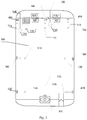
- Fig. 1 illustrates a schematic view of an antenna device for a mobile terminal according to an embodiment of the present disclosure.
- the mobile terminal can be a mobile phone, a tablet computer, a palmtop, a personal digital assistant and other hardware devices having various operating systems.
- Fig. 1 illustrates the antenna device according to embodiments of the present disclosure.
- the antenna device can include a plurality of antennas 100, a mainboard 200, a metal battery cover 300 and a plurality of first connecting members 400.
- the mainboard 200 can include a plurality of feed sources 210.
- the plurality of feed sources 210 may be coupled to the plurality of antennas 100 respectively, i.e. one antenna 100 can be coupled to one feed source 210.
- the feed source 210 is a primary radiator that excites a primary reflective surface and a secondary reflective surface of a surface antenna, and is a critical component for determining an electrical characteristic and a frequency band of the antenna 100 connected thereto.
- the feed source 210 is configured to radiate a radio frequency power from a feed line in a form of electromagnetic waves to the reflective surfaces or a lens, such that an appropriate field distribution can be produced around an aperture to form a desired sharp wave beam or shaped wave beam, and the power that leaks out from edges of the primary reflective surface, the secondary reflective surface or the lens can be made as small as possible, thereby achieving as high a gain as possible. That is, a main function of the feed source 210 is to collect an electromagnetic wave signal received by the antenna 100 coupled to the feed source 210, convert the collected electromagnetic wave signal into a signal voltage and supply it to a tuner, and polarize the received electromagnetic wave.
- M1, M2, M3, SW2, and SW3, SW denotes an antenna switch module
- M denotes an antenna match module which is configured to adjust a work frequency band of an antenna system and achieve impedance matching of the antenna system.
- the antenna 100 can include but is not limited to one or more of a GPS antenna, a Wi-Fi antenna and a communication antenna.
- the antenna 100 can be any of the GPS antenna, the Wi-Fi antenna or the communication antenna; for another example, the antenna 100 can be a two-in-one antenna composed of the GPS antenna and the Wi-Fi antenna; for still another example, the antenna 100 can be a two-in-one antenna composed of the GPS antenna and the communication antenna.
- the communication antenna can be a cellular mobile communication antenna, for instance, an antenna for 2G/3G/4G communication.
- the metal battery cover 300 can include a plurality of first ground points 310. Locations corresponding to the first ground points 310 are used for grounding, such that a purpose of grounding can be achieved when other components (like the feed source) of the mobile terminal are coupled to the first ground points 310.
- the plurality of first connecting members 400 couple the plurality of first ground points 310 to a plurality of second ground points 220 of the mainboard 200, in which the plurality of second ground points 220 correspond to the plurality of feed sources 210 respectively.
- the correspondence between the plurality of second ground points 220 and the plurality of the feed sources 210 means that the plurality of second ground points 220 are adjacent to the plurality of the feed sources 210, i.e., one second ground point 220 is relatively adjacent to one feed source 210.
- the number of the first ground points 310 can be more than one, such as two, four or eight.
- four first ground points 310 may be provided at four corner areas of the metal battery cover 300 respectively, that is, one first ground point may be situated at one corner area of the metal battery cover 300.
- four first connecting members 400 can be provided to connect the first ground points 310 with the second ground points 220.
- each corner of the metal battery cover 300 is provided with one first ground point 310
- the first connecting member 400 for connecting the first ground point 310 with the second ground point 220 is also provided in each of the four corner areas of the metal battery cover 300.
- locations at the four corner areas of the metal battery cover can be used as the ground points, and the ground points can be connected with each other through the connecting members, which can eliminate or alleviate the impact of the metal battery cover on the antenna performance effectively.
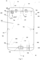
- the metal battery cover 300 can further include a plurality of third ground points 320.
- the antenna device can further include a plurality of second connecting members 500, and the plurality of second connecting members 500 can couple the plurality of third ground points 320 with a ground wire of the mainboard 200.
- the metal battery cover 300 can have four sides, and the four third ground points 320 can be located at midpoints of the four sides respectively. That is, the midpoint of each side of the metal battery cover 300 is provided with one third ground point 320, and regarding each third ground point 320, one second connecting member 500 can be used to connect the third ground point 320 with the ground wire of the mainboard 200.
- the antenna device can further include a plurality of first capacitors 600 and a plurality of second capacitors 700.
- the plurality of first capacitors 600 can be connected between the plurality of first connecting members 400 and the plurality of first ground points 310 respectively, and the plurality of second capacitors 700 can be connected between the plurality of second connecting members 500 and the plurality of third ground points 320 respectively. That is, one first capacitor 600 can be provided between one first connecting member 400 and one first ground point 310, and one second capacitor 700 can be provided between one second connecting member 500 and one third ground point 320.
- a large capacitor is connected in series in a ground circuit and usually has a capacitance in the range of 80PF ⁇ 150PF, as one implementation, around 100PF, such that leakage during charging can be avoided on the one hand, thereby preventing leakage current from flowing into the metal battery cover and protecting a human in contact with the battery cover from getting an electric shock, and this capacitor is equivalent to a short circuit for a radio frequency signal and therefore does not affect the grounding of the metal battery cover on the other hand.
- first connecting member 400 and the second connecting member 500 can be various as long as they are electrically conductive.
- first connecting member 400 and/or the second connecting member 500 can be resilient sheets, screws or pogo pin connectors, etc. Therefore, by utilizing the conductive property of the resilient sheets, screws or spring pin connectors, etc., the excited current on the metal battery cover can be conducted to the ground wire of the mainboard quickly, adverse effects on the antenna performance due to the secondary radiation of the metal battery cover can be effectively eliminated or alleviated.
- the antenna device can further include a plurality of first conductive fabrics and a plurality of second conductive fabrics.
- Each of the plurality of first conductive fabrics is located between each first ground point 310 and each corresponding first connecting member 400, and the each of the plurality of second conductive fabrics is located between each third ground point 320 and each corresponding second connecting member 500.
- the plurality of first conductive fabrics and the plurality of second conductive fabrics can be a plurality of gold-plated conductive fabrics or the like.
- the plurality of first ground points are provided in the metal battery cover and the plurality of first ground points are connected with the plurality of second ground points of the mainboard through the plurality of first connecting members respectively, in which the plurality of second ground points correspond to the plurality of feed sources respectively.
- a plurality of locations on the metal battery cover can be used as the ground points, and moreover, the ground points can be connected with each other through the connecting members, such that the excited current on the surface of the metal battery cover can quickly return to the ground wire of the mainboard through loops composed of the connecting members and the ground points, which can effectively reduce adverse effects on the antenna performance due to the secondary radiation.
- a structure for the metal battery cover and the antenna in the antenna device is applicable to designs including but not limited to a flexible printed circuit (FPC) antenna, a laser-direction-structuring (LDS) antenna, a metal middle-frame antenna, an all-metal battery cover antenna and so on.
- FPC flexible printed circuit
- LDS laser-direction-structuring
- a mobile terminal is also provided in the present disclosure.
- Fig. 4 illustrates a schematic view of a mobile terminal according to an embodiment of the present disclosure.
- the mobile terminal 1 can include an antenna device, a rear camera 20, a support structure 30, a front fingerprint module 40 and a headphone socket 50.
- Detailed structures and functions of the antenna device can refer to the detailed description of that of the antenna device illustrated in Figs. 1 to 3 , and thus will not be elaborated herein.
- the rear camera 20 is embedded in the support structure 30, such that the support structure 30 can be configured to support the rear camera 20.
- the support structure 30 can be located in a groove of the mainboard and connected with the ground wire of the mainboard.
- the front fingerprint module 40 can be located in a central lower part of a front surface of the mobile terminal 1 and configured to collect and identify a user's fingerprint.
- the user's fingerprint can be identified by the front fingerprint module, and various functions (such as unlocking of the mobile terminal, payment, and other functions) can be realized through the user's fingerprint.
- the headphone socket 50 can be located in the bottom right of the mobile terminal 1.
- the headphone socket 50 is provided with a headphone jack into which a headphone can be inserted, and audio information transmission can be implemented through a sound track or a similar module in the headphone socket 50.
- the mobile terminal can further include other components (such as a processor, a memory, a battery module etc.) to realize other functions, which will not be elaborated herein.
- other components such as a processor, a memory, a battery module etc.
- the plurality of first ground points are provided in the metal battery cover of the mobile terminal and the plurality of first ground points are coupled to the plurality of second ground points of the mainboard through the plurality of first connecting members, in which the plurality of second ground points correspond to the plurality of feed sources respectively.
- the plurality of locations on the metal battery cover are configured as the ground points; moreover, the ground points can be connected with each other through the connecting members, such that the excited current on the surface of the metal battery cover can quickly return to the ground wire of the mainboard through loops composed of the connecting members and the ground points.
- the large capacitor is connected in series in the ground circuit, such that the leakage can be avoided during the charging on the one hand, thereby preventing the leakage current from flowing to the metal battery cover and protecting the human in contact with the battery cover from getting the electric shock, and on the other hand, this capacitor is equivalent to a short circuit for the radio frequency signal and will not affect the grounding of the metal battery cover, thereby effectively avoiding adverse effects on the antenna performance due to the secondary radiation.
- first and second are used herein for purposes of description and are not intended to indicate or imply relative importance or significance or to imply the number of indicated technical features.
- the feature defined with “first” and “second” can comprise one or more of this feature.
- the term “a plurality of” means two or more than two, unless specified otherwise.
- the terms “mounted”, “connected”, “coupled”, “fixed” and the like are used broadly, and can be, for example, fixed connections, detachable connections, or integral connections; can also be mechanical or electrical connections or communicated with each other; can also be direct connections or indirect connections via intervening structures; can also be inner communications or mutual interaction of two elements, which can be understood by those skilled in the art according to specific situations.
- a structure in which a first feature is "on" or “below” a second feature can include an embodiment in which the first feature is in direct contact with the second feature, and can also include an embodiment in which the first feature and the second feature are not in direct contact with each other, but are contacted via an additional feature formed therebetween.
- a first feature "on,” “above,” or “on top of” a second feature can include an embodiment in which the first feature is right or obliquely “on,” “above,” or “on top of” the second feature, or just means that the first feature is at a height higher than that of the second feature; while a first feature “below,” “under,” or “on bottom of” a second feature can include an embodiment in which the first feature is right or obliquely “below,” “under,” or “on bottom of” the second feature, or just means that the first feature is at a height lower than that of the second feature.
Landscapes
- Engineering & Computer Science (AREA)
- Computer Networks & Wireless Communication (AREA)
- Telephone Set Structure (AREA)
- Support Of Aerials (AREA)
Abstract
Description
- The present disclosure relates to a field of mobile terminal manufacturing technology, and particularly, to an antenna device for a mobile terminal and a mobile terminal.
- With the rapid development of the mobile terminal manufacturing technology and the increasingly high daily needs, more and more users expect the mobile terminal to have a more dazzling appearance to show their own personalities. A mobile terminal with a metal battery cover becomes more and more popular among the users due to its expressive appearance. However, conductivity of the metal battery cover causes secondary radiation, which may adversely affect the antenna performance. It is necessary to process the metal battery cover in order to effectively reduce a negative impact of the metal battery cover on the antenna. Therefore, an urgent problem to be solved is how to design or arrange the structural or positional relationship between the metal battery cover and the antenna so as to effectively address the negative impact of the metal battery cover on the antenna performance.
- The present disclosure aims to solve at least one of the technical problems above in the related art.
- Accordingly, a first objective of the present disclosure is to provide an antenna device for a mobile terminal. The antenna device can effectively avoid adverse effects on the antenna performance due to secondary radiation.
- A second objective of the present disclosure is to provide a mobile terminal.
- To attain the first objective, embodiments of a first aspect of present disclosure provides an antenna device for a mobile terminal. The antenna device includes: a plurality of antennas; a metal battery cover including a plurality of first ground points; a mainboard comprising a plurality of feed sources and a plurality of second ground points corresponding to the plurality of feed sources, the plurality of feed sources being coupled to the plurality of antennas; and a plurality of first connecting members coupling the plurality of first ground points to the plurality of second ground points of the mainboard.
- For the antenna device according to embodiments of the present disclosure, the plurality of first ground points are provided in the metal battery cover and the plurality of first ground points are coupled to the plurality of second ground points of the mainboard through the plurality of first connecting members, in which the plurality of second ground points correspond to the plurality of feed sources respectively. As such, a plurality of locations on the metal battery cover are configured as the ground points, and moreover, the ground points can be connected with each other through the connecting members, such that an excited current on a surface of the metal battery cover can quickly return to a ground wire of the mainboard through loops composed of the connecting members and the ground points, which can effectively avoid adverse effects on the antenna performance due to the secondary radiation.
- In addition, the antenna device according to embodiments of the present disclosure can have additional technical features as follows.
- In an embodiment, the metal battery cover further includes a plurality of third ground points, the mainboard further comprises a ground wire, and the antenna device further includes a plurality of second connecting members coupling the plurality of third ground points to the ground wire of the mainboard.
- In an embodiment, four third ground points are provided, the metal battery cover includes four sides, and the four third ground points are located at midpoints of the four sides respectively.
- In an embodiment, four first ground points are provided and located at four corner areas of the metal battery cover one to one.
- In an embodiment, four first connecting members are provided and located at the four corner areas of the metal battery cover one to one.
- In an embodiment, the antenna device further includes a plurality of first capacitors coupled between the plurality of first connecting members and the plurality of first ground points respectively.
- In an embodiment, each of the plurality of first capacitors has a capacitance in the range of 80PF∼150PF.
- In an embodiment, the antenna device further includes a plurality of second capacitors coupled between the plurality of second connecting members and the plurality of third ground points respectively.
- In an embodiment, each of the plurality of second capacitors has a capacitance in the range of 80PF∼150PF.
- In an embodiment, the plurality of antennas include one or more of a GPS antenna, a Wi-Fi antenna and a communication antenna.
- In an embodiment, the first connecting member and the second connecting member are configured as a resilient sheet, a screw or a pogo pin connector.
- In an embodiment, the antenna device further includes: a plurality of first conductive fabrics and a plurality of second conductive fabrics, each of the plurality of first conductive fabrics being located between each first ground point and each corresponding first connecting member; and each of the plurality of second conductive fabrics being located between each third ground point and each corresponding second connecting member.
- In an embodiment, the first conductive fabric and the second conductive fabric each are configured as a gold-plated conductive fabric.
- To attain the second objective, embodiments of a second aspect of present disclosure provides a mobile terminal. The mobile terminal includes the antenna device according to embodiments of the first aspect of present disclosure.
- In an embodiment, the mobile terminal further includes a rear camera and a support structure, and the rear camera is embedded in the support structure.
- For the mobile terminal according to embodiments of the present disclosure, the plurality of first ground points are provided in the metal battery cover of the mobile terminal and the plurality of first ground points are coupled to the plurality of second ground points of the mainboard through the plurality of first connecting members, in which the plurality of second ground points correspond to the plurality of feed sources respectively. As such, the plurality of locations on the metal battery cover are configured as the ground points, and moreover, the ground points can be connected through the connecting members, such that the excited current on the surface of the metal battery cover can quickly return to the ground wire of the mainboard through loops composed of the connecting members and the ground points, which can effectively avoid adverse effects on the antenna performance due to the secondary radiation.
- Additional aspects and advantages of embodiments of present disclosure will be given in part in the following descriptions, become apparent in part from the following descriptions, or be learned from the practice of the embodiments of the present disclosure.
- These and/or other aspects and advantages of the present disclosure will become apparent and more readily appreciated from the following descriptions of embodiments made with reference to the drawings, in which:
-
Fig. 1 is a schematic view of an antenna device for a mobile terminal according to an embodiment of the present disclosure. -
Fig. 2 is a schematic view of an antenna device for a mobile terminal according to another embodiment of the present disclosure. -
Fig. 3 is a schematic view of an antenna device for a mobile terminal according to still another embodiment of the present disclosure. -
Fig. 4 is a schematic view of a mobile terminal according to an embodiment of the present disclosure. - 100 antenna, 200 mainboard, 300 metal battery cover, 400 first connecting member, 210 feed source, 310 first ground point, 220 second ground point, 320 third ground point, 500 second connecting member, 600 first capacitor, 700 second capacitor, 1 mobile terminal, 20 rear camera, 30 support structure, 40 front fingerprint module, 50 headphone socket.
- Reference will be made in detail to embodiments of the present disclosure. Examples of the embodiments are illustrated in the drawings. The embodiments described herein with reference to drawings are explanatory, and used to interpret the present disclosure. The embodiments shall not be construed to limit the present disclosure.
- In the following, an antenna device for a mobile terminal as well as a mobile terminal according to embodiments of the present disclosure will be described with reference to the accompanying drawings.
-
Fig. 1 illustrates a schematic view of an antenna device for a mobile terminal according to an embodiment of the present disclosure. It should be noted that in embodiments of the present disclosure, the mobile terminal can be a mobile phone, a tablet computer, a palmtop, a personal digital assistant and other hardware devices having various operating systems. -
Fig. 1 illustrates the antenna device according to embodiments of the present disclosure. The antenna device can include a plurality ofantennas 100, amainboard 200, ametal battery cover 300 and a plurality of first connectingmembers 400. - As illustrated in
Fig. 1 , themainboard 200 can include a plurality offeed sources 210. The plurality offeed sources 210 may be coupled to the plurality ofantennas 100 respectively, i.e. oneantenna 100 can be coupled to onefeed source 210. Thefeed source 210 is a primary radiator that excites a primary reflective surface and a secondary reflective surface of a surface antenna, and is a critical component for determining an electrical characteristic and a frequency band of theantenna 100 connected thereto. Thefeed source 210 is configured to radiate a radio frequency power from a feed line in a form of electromagnetic waves to the reflective surfaces or a lens, such that an appropriate field distribution can be produced around an aperture to form a desired sharp wave beam or shaped wave beam, and the power that leaks out from edges of the primary reflective surface, the secondary reflective surface or the lens can be made as small as possible, thereby achieving as high a gain as possible. That is, a main function of thefeed source 210 is to collect an electromagnetic wave signal received by theantenna 100 coupled to thefeed source 210, convert the collected electromagnetic wave signal into a signal voltage and supply it to a tuner, and polarize the received electromagnetic wave. Regarding M1, M2, M3, SW2, and SW3, SW denotes an antenna switch module, and M denotes an antenna match module which is configured to adjust a work frequency band of an antenna system and achieve impedance matching of the antenna system. - It should be noted that the
antenna 100 can include but is not limited to one or more of a GPS antenna, a Wi-Fi antenna and a communication antenna. For example, theantenna 100 can be any of the GPS antenna, the Wi-Fi antenna or the communication antenna; for another example, theantenna 100 can be a two-in-one antenna composed of the GPS antenna and the Wi-Fi antenna; for still another example, theantenna 100 can be a two-in-one antenna composed of the GPS antenna and the communication antenna. In embodiments of the present disclosure, the communication antenna can be a cellular mobile communication antenna, for instance, an antenna for 2G/3G/4G communication. - The
metal battery cover 300 can include a plurality offirst ground points 310. Locations corresponding to thefirst ground points 310 are used for grounding, such that a purpose of grounding can be achieved when other components (like the feed source) of the mobile terminal are coupled to thefirst ground points 310. - The plurality of first connecting
members 400 couple the plurality of first ground points 310 to a plurality of second ground points 220 of themainboard 200, in which the plurality of second ground points 220 correspond to the plurality offeed sources 210 respectively. It should be noted that the correspondence between the plurality of second ground points 220 and the plurality of thefeed sources 210 means that the plurality of second ground points 220 are adjacent to the plurality of thefeed sources 210, i.e., onesecond ground point 220 is relatively adjacent to onefeed source 210. Thus, it is possible to guarantee the grounding for lightning protection of the antenna coupled to the feed source. - In conclusion, by using a plurality of areas of the metal battery cover as the ground points, and connecting the ground points with each other through the connecting members, the impact of the metal battery cover on antenna performance can be reduced effectively.
- It could be understood that the number of the first ground points 310 can be more than one, such as two, four or eight. As an example, four first ground points 310 may be provided at four corner areas of the
metal battery cover 300 respectively, that is, one first ground point may be situated at one corner area of themetal battery cover 300. In this example, when four first ground points 310 are provided, four first connectingmembers 400 can be provided to connect the first ground points 310 with the second ground points 220. For example, as illustrated inFig. 1 , each corner of themetal battery cover 300 is provided with onefirst ground point 310, and the first connectingmember 400 for connecting thefirst ground point 310 with thesecond ground point 220 is also provided in each of the four corner areas of themetal battery cover 300. Thus, locations at the four corner areas of the metal battery cover can be used as the ground points, and the ground points can be connected with each other through the connecting members, which can eliminate or alleviate the impact of the metal battery cover on the antenna performance effectively. - To further reduce the impact of the metal battery cover on the antenna performance, as an example, as illustrated in
Fig. 2 , themetal battery cover 300 can further include a plurality of third ground points 320. In this example, the antenna device can further include a plurality of second connectingmembers 500, and the plurality of second connectingmembers 500 can couple the plurality of third ground points 320 with a ground wire of themainboard 200. - In an embodiment of the present disclosure, as illustrated in
Fig. 2 , four third ground points 320 can be provided. Themetal battery cover 300 can have four sides, and the four third ground points 320 can be located at midpoints of the four sides respectively. That is, the midpoint of each side of themetal battery cover 300 is provided with onethird ground point 320, and regarding eachthird ground point 320, one second connectingmember 500 can be used to connect thethird ground point 320 with the ground wire of themainboard 200. - Therefore, by connecting the first ground point with the second ground point of the mainboard through the first connecting member and connecting the third ground point with the ground wire of the mainboard through the second connecting member, when the
antenna 100 receives or transmits a signal, an excited current on a surface of the metal battery cover can quickly return to the ground wire of the mainboard through the first connecting member and the second connecting member, which can effectively avoid adverse effects on the antenna performance due to secondary radiation. - In order to effectively avoid problems (such as static electricity) caused by a charged battery cover due to a short circuit, as an example, as illustrated in
Fig. 3 , the antenna device can further include a plurality offirst capacitors 600 and a plurality ofsecond capacitors 700. The plurality offirst capacitors 600 can be connected between the plurality of first connectingmembers 400 and the plurality of first ground points 310 respectively, and the plurality ofsecond capacitors 700 can be connected between the plurality of second connectingmembers 500 and the plurality of third ground points 320 respectively. That is, onefirst capacitor 600 can be provided between one first connectingmember 400 and onefirst ground point 310, and onesecond capacitor 700 can be provided between one second connectingmember 500 and onethird ground point 320. As such, a large capacitor is connected in series in a ground circuit and usually has a capacitance in the range of 80PF∼150PF, as one implementation, around 100PF, such that leakage during charging can be avoided on the one hand, thereby preventing leakage current from flowing into the metal battery cover and protecting a human in contact with the battery cover from getting an electric shock, and this capacitor is equivalent to a short circuit for a radio frequency signal and therefore does not affect the grounding of the metal battery cover on the other hand. - It could be understood that materials and structures of the first connecting
member 400 and the second connectingmember 500 can be various as long as they are electrically conductive. As an example, the first connectingmember 400 and/or the second connectingmember 500 can be resilient sheets, screws or pogo pin connectors, etc. Therefore, by utilizing the conductive property of the resilient sheets, screws or spring pin connectors, etc., the excited current on the metal battery cover can be conducted to the ground wire of the mainboard quickly, adverse effects on the antenna performance due to the secondary radiation of the metal battery cover can be effectively eliminated or alleviated. - In order to effectively avoid a problem of conductive failure between the connecting member and the ground point due to falling-off from a relatively low height, oxidation and other harsh circumstances, in an embodiment of the present disclosure, the antenna device can further include a plurality of first conductive fabrics and a plurality of second conductive fabrics. Each of the plurality of first conductive fabrics is located between each
first ground point 310 and each corresponding first connectingmember 400, and the each of the plurality of second conductive fabrics is located between eachthird ground point 320 and each corresponding second connectingmember 500. In the embodiment of the present disclosure, the plurality of first conductive fabrics and the plurality of second conductive fabrics can be a plurality of gold-plated conductive fabrics or the like. Thus, by attaching the plurality of gold-plated conductive fabrics to a contact portion of the metal battery cover, it is possible to address a problem that the radio frequency impedance is too large due to poor contact caused by various harsh circumstances. - For the antenna device according to embodiments of the present disclosure, the plurality of first ground points are provided in the metal battery cover and the plurality of first ground points are connected with the plurality of second ground points of the mainboard through the plurality of first connecting members respectively, in which the plurality of second ground points correspond to the plurality of feed sources respectively. As such, a plurality of locations on the metal battery cover can be used as the ground points, and moreover, the ground points can be connected with each other through the connecting members, such that the excited current on the surface of the metal battery cover can quickly return to the ground wire of the mainboard through loops composed of the connecting members and the ground points, which can effectively reduce adverse effects on the antenna performance due to the secondary radiation.
- It should be noted that a structure for the metal battery cover and the antenna in the antenna device according to embodiments of the present disclosure is applicable to designs including but not limited to a flexible printed circuit (FPC) antenna, a laser-direction-structuring (LDS) antenna, a metal middle-frame antenna, an all-metal battery cover antenna and so on.
- In order to implement the above embodiments, a mobile terminal is also provided in the present disclosure.
-
Fig. 4 illustrates a schematic view of a mobile terminal according to an embodiment of the present disclosure. As illustrated inFig. 4 , the mobile terminal 1 can include an antenna device, arear camera 20, asupport structure 30, afront fingerprint module 40 and aheadphone socket 50. - Detailed structures and functions of the antenna device can refer to the detailed description of that of the antenna device illustrated in
Figs. 1 to 3 , and thus will not be elaborated herein. - As illustrated in
Fig. 4 , therear camera 20 is embedded in thesupport structure 30, such that thesupport structure 30 can be configured to support therear camera 20. Thesupport structure 30 can be located in a groove of the mainboard and connected with the ground wire of the mainboard. - The
front fingerprint module 40 can be located in a central lower part of a front surface of the mobile terminal 1 and configured to collect and identify a user's fingerprint. Thus, the user's fingerprint can be identified by the front fingerprint module, and various functions (such as unlocking of the mobile terminal, payment, and other functions) can be realized through the user's fingerprint. - The
headphone socket 50 can be located in the bottom right of the mobile terminal 1. Theheadphone socket 50 is provided with a headphone jack into which a headphone can be inserted, and audio information transmission can be implemented through a sound track or a similar module in theheadphone socket 50. - It could be understood that the above description only involves inventive components in the mobile terminal, and in addition to the above components, the mobile terminal can further include other components (such as a processor, a memory, a battery module etc.) to realize other functions, which will not be elaborated herein.
- For the mobile terminal according to embodiments of the present disclosure, the plurality of first ground points are provided in the metal battery cover of the mobile terminal and the plurality of first ground points are coupled to the plurality of second ground points of the mainboard through the plurality of first connecting members, in which the plurality of second ground points correspond to the plurality of feed sources respectively. As such, the plurality of locations on the metal battery cover are configured as the ground points; moreover, the ground points can be connected with each other through the connecting members, such that the excited current on the surface of the metal battery cover can quickly return to the ground wire of the mainboard through loops composed of the connecting members and the ground points. Moreover, the large capacitor is connected in series in the ground circuit, such that the leakage can be avoided during the charging on the one hand, thereby preventing the leakage current from flowing to the metal battery cover and protecting the human in contact with the battery cover from getting the electric shock, and on the other hand, this capacitor is equivalent to a short circuit for the radio frequency signal and will not affect the grounding of the metal battery cover, thereby effectively avoiding adverse effects on the antenna performance due to the secondary radiation.
- In the specification, it is to be understood that terms such as "central," "longitudinal," "transverse," "length," "width," "thickness," "upper," "lower," "front," "rear," "left," "right," "vertical," "horizontal," "top," "bottom," "inner," "outer," "clockwise," "counterclockwise," "axial," "radial" and "circumferential" should be construed to refer to the orientations or positions as described or as illustrated in the drawings under discussion. These relative terms are for convenience of description and do not indicate or imply that the device or element referred to must have a particular orientation or be constructed or operated in a particular orientation. Thus, the relative terms shall not be construed to limit the present disclosure.
- In addition, terms such as "first" and "second" are used herein for purposes of description and are not intended to indicate or imply relative importance or significance or to imply the number of indicated technical features. Thus, the feature defined with "first" and "second" can comprise one or more of this feature. In the description of the present disclosure, the term "a plurality of" means two or more than two, unless specified otherwise.
- In the present disclosure, unless specified or limited otherwise, the terms "mounted", "connected", "coupled", "fixed" and the like are used broadly, and can be, for example, fixed connections, detachable connections, or integral connections; can also be mechanical or electrical connections or communicated with each other; can also be direct connections or indirect connections via intervening structures; can also be inner communications or mutual interaction of two elements, which can be understood by those skilled in the art according to specific situations.
- In the present disclosure, unless specified or limited otherwise, a structure in which a first feature is "on" or "below" a second feature can include an embodiment in which the first feature is in direct contact with the second feature, and can also include an embodiment in which the first feature and the second feature are not in direct contact with each other, but are contacted via an additional feature formed therebetween. Furthermore, a first feature "on," "above," or "on top of" a second feature can include an embodiment in which the first feature is right or obliquely "on," "above," or "on top of" the second feature, or just means that the first feature is at a height higher than that of the second feature; while a first feature "below," "under," or "on bottom of" a second feature can include an embodiment in which the first feature is right or obliquely "below," "under," or "on bottom of" the second feature, or just means that the first feature is at a height lower than that of the second feature.
- Reference throughout this specification to "an embodiment", "some embodiments", "an example", "a specific example" or "some examples" means that a particular feature, structure, material, or characteristic described in connection with the embodiment or example is included in at least one embodiment or example of the present disclosure. Thus, the appearances of the above phrases throughout this specification are not necessarily referring to the same embodiment or example of the present disclosure. Furthermore, the particular features, structures, materials, or characteristics can be combined in any suitable manner in one or more embodiments or examples. Moreover, different embodiments or examples as well as the features in the different embodiments or examples described in the specification can be combined or united by those skilled in the related art in the absence of contradictory circumstances.
- Although embodiments of the present disclosure have been shown and illustrated, it shall be understood by those skilled in the art that the above embodiments are explanatory and cannot be construed to limit the present disclosure, and changes, modifications, alternatives and variants can be made in the embodiments without departing from the scope of the present disclosure.
Claims (15)
- An antenna device for a mobile terminal, comprising:a plurality of antennas (100);a metal battery cover (300) comprising a plurality of first ground points (310);a mainboard (200) comprising a plurality of feed sources (210) and a plurality of second ground points (220) corresponding to the plurality of feed sources (210), the plurality of feed sources (210) being coupled to the plurality of antennas (100); anda plurality of first connecting members (400) coupling the plurality of first ground points (310) to the plurality of second ground points (220) of the mainboard (200).
- The antenna device according to claim 1, wherein the metal battery cover (300) further comprises a plurality of third ground points (320), the mainboard (200) further comprises a ground wire, and the antenna device further comprises a plurality of second connecting members (500) coupling the plurality of third ground points (320) to the ground wire of the mainboard (200).
- The antenna device according to claim 2, wherein four third ground points (320) are provided, the metal battery cover (300) comprises four sides, and the four third ground points (320) are located at midpoints of the four sides respectively.
- The antenna device according to claim 1, wherein four first ground points (310) are provided and located at four corner areas of the metal battery cover (300) one to one.
- The antenna device according to claim 4, wherein four first connecting members (400) are provided and located at the four corner areas of the metal battery cover (300) one to one.
- The antenna device according to claim 1, further comprising a plurality of first capacitors (600) coupled between the plurality of first connecting members (400) and the plurality of first ground points (310) respectively.
- The antenna device according to claim 6, wherein each of the plurality of first capacitors (600) has a capacitance in the range of 80PF∼150PF.
- The antenna device according to claim 2, further comprising a plurality of second capacitors (700) coupled between the plurality of second connecting members (500) and the plurality of third ground points (320) respectively.
- The antenna device according to claim 8, wherein each of the plurality of second capacitors (700) has a capacitance in the range of 80PF∼150PF.
- The antenna device according to claim 1, wherein the plurality of antennas (100) comprise one or more of a GPS antenna, a Wi-Fi antenna and a communication antenna.
- The antenna device according to claim 2, wherein the first connecting member (400) and the second connecting member (500) are configured as a resilient sheet, a screw or a pogo pin connector.
- The antenna device according to claim 2, further comprising a plurality of first conductive fabrics and a plurality of second conductive fabrics, each of the plurality of first conductive fabrics being located between each first ground point (310) and each corresponding first connecting member (400); and each of the plurality of second conductive fabrics being located between each third ground point (320) and each corresponding second connecting member (500).
- The antenna device according to claim 12, wherein the first conductive fabric and the second conductive fabric each are configured as a gold-plated conductive fabric.
- A mobile terminal, comprising an antenna device according to any one of claims 1 to 13.
- The mobile terminal according to claim 14, further comprising a rear camera and a support structure, and the rear camera is embedded in the support structure.
Applications Claiming Priority (2)
| Application Number | Priority Date | Filing Date | Title |
|---|---|---|---|
| CN201621257004.9U CN206194946U (en) | 2016-11-18 | 2016-11-18 | Mobile terminal's antenna device and mobile terminal |
| CN201611036734.0A CN106410373B (en) | 2016-11-18 | 2016-11-18 | Antenna device of mobile terminal and mobile terminal |
Publications (2)
| Publication Number | Publication Date |
|---|---|
| EP3324483A1 true EP3324483A1 (en) | 2018-05-23 |
| EP3324483B1 EP3324483B1 (en) | 2020-03-25 |
Family
ID=59506157
Family Applications (1)
| Application Number | Title | Priority Date | Filing Date |
|---|---|---|---|
| EP17184222.2A Active EP3324483B1 (en) | 2016-11-18 | 2017-08-01 | Antenna device for mobile terminal and mobile terminal |
Country Status (4)
| Country | Link |
|---|---|
| US (2) | US10312585B2 (en) |
| EP (1) | EP3324483B1 (en) |
| ES (1) | ES2793337T3 (en) |
| WO (1) | WO2018090669A1 (en) |
Cited By (1)
| Publication number | Priority date | Publication date | Assignee | Title |
|---|---|---|---|---|
| CN109216872A (en) * | 2018-09-06 | 2019-01-15 | 北京小米移动软件有限公司 | Terminal |
Families Citing this family (3)
| Publication number | Priority date | Publication date | Assignee | Title |
|---|---|---|---|---|
| EP3588932B1 (en) * | 2018-06-26 | 2023-07-05 | Ricoh Company, Ltd. | Imaging device |
| KR102645286B1 (en) | 2019-04-30 | 2024-03-11 | 삼성전자주식회사 | Antenna radiator including a plurality of layers and electronic device including the same |
| CN115275564A (en) * | 2021-04-30 | 2022-11-01 | Oppo广东移动通信有限公司 | Antenna device and mobile terminal |
Citations (6)
| Publication number | Priority date | Publication date | Assignee | Title |
|---|---|---|---|---|
| EP1367803A2 (en) * | 2002-05-30 | 2003-12-03 | Nec Corporation | Arrangement for reducing of electromagnetic interferences in a circuit by connecting the conductive cover of a battery at plurality of locations to the ground-layer |
| JP2009194223A (en) * | 2008-02-15 | 2009-08-27 | Sony Ericsson Mobilecommunications Japan Inc | Mobile terminal device and method of grounding mobile terminal device |
| US8000738B2 (en) * | 2006-11-16 | 2011-08-16 | Lg Electronics Inc. | Mobile terminal with leakage current prevention |
| WO2012144197A1 (en) * | 2011-04-22 | 2012-10-26 | パナソニック株式会社 | Portable wireless terminal |
| CN104241870A (en) * | 2013-06-14 | 2014-12-24 | 李展 | Combined antenna for mobile device and manufacturing method for combined antenna |
| EP3001649A1 (en) * | 2013-05-22 | 2016-03-30 | Huawei Device Co., Ltd. | Mobile terminal |
Family Cites Families (15)
| Publication number | Priority date | Publication date | Assignee | Title |
|---|---|---|---|---|
| KR100696886B1 (en) * | 2004-09-17 | 2007-03-20 | 삼성전자주식회사 | Built-in antenna device of portable wireless terminal |
| KR20100068896A (en) * | 2008-12-15 | 2010-06-24 | 삼성전자주식회사 | Antenna device for portable wireless terminal |
| CN201966972U (en) * | 2011-02-24 | 2011-09-07 | 惠州卡美欧通讯有限公司 | Flip phone capable of improving performance of antenna |
| KR101801186B1 (en) * | 2011-02-25 | 2017-11-24 | 엘지전자 주식회사 | Mobile terminal |
| KR101257093B1 (en) * | 2011-06-10 | 2013-04-19 | 엘지전자 주식회사 | Mobile terminal |
| CN104701619B (en) * | 2014-12-31 | 2017-08-01 | 东莞劲胜精密组件股份有限公司 | A kind of loop checking installation closure wireloop antenna and mobile device |
| CN205050981U (en) * | 2015-01-22 | 2016-02-24 | 讯创(天津)电子有限公司 | Full metallic structure terminal communications facilities's antenna device and electronic equipment thereof |
| JP6493788B2 (en) * | 2015-02-24 | 2019-04-03 | 日立金属株式会社 | Antenna device |
| WO2016154851A1 (en) * | 2015-03-30 | 2016-10-06 | 华为技术有限公司 | Terminal |
| CN106159445A (en) * | 2015-04-28 | 2016-11-23 | 比亚迪股份有限公司 | Antenna and the mobile terminal with it |
| KR101751347B1 (en) * | 2015-06-16 | 2017-07-11 | 엘지전자 주식회사 | Mobile terminal and method of controlling the same |
| CN205039252U (en) * | 2015-10-21 | 2016-02-17 | 深圳市信维通信股份有限公司 | Antenna structure and electronic equipment based on single breach metal frame |
| CN106129616B (en) * | 2016-07-20 | 2019-03-26 | 瑞声精密制造科技(常州)有限公司 | The electronic equipment of antenna system and the application system |
| CN206194946U (en) * | 2016-11-18 | 2017-05-24 | 广东欧珀移动通信有限公司 | Mobile terminal's antenna device and mobile terminal |
| CN106410373B (en) * | 2016-11-18 | 2020-06-05 | Oppo广东移动通信有限公司 | Antenna device of mobile terminal and mobile terminal |
-
2017
- 2017-07-31 WO PCT/CN2017/095352 patent/WO2018090669A1/en not_active Ceased
- 2017-08-01 EP EP17184222.2A patent/EP3324483B1/en active Active
- 2017-08-01 ES ES17184222T patent/ES2793337T3/en active Active
- 2017-08-04 US US15/668,778 patent/US10312585B2/en active Active
-
2019
- 2019-04-24 US US16/393,265 patent/US10707571B2/en not_active Expired - Fee Related
Patent Citations (6)
| Publication number | Priority date | Publication date | Assignee | Title |
|---|---|---|---|---|
| EP1367803A2 (en) * | 2002-05-30 | 2003-12-03 | Nec Corporation | Arrangement for reducing of electromagnetic interferences in a circuit by connecting the conductive cover of a battery at plurality of locations to the ground-layer |
| US8000738B2 (en) * | 2006-11-16 | 2011-08-16 | Lg Electronics Inc. | Mobile terminal with leakage current prevention |
| JP2009194223A (en) * | 2008-02-15 | 2009-08-27 | Sony Ericsson Mobilecommunications Japan Inc | Mobile terminal device and method of grounding mobile terminal device |
| WO2012144197A1 (en) * | 2011-04-22 | 2012-10-26 | パナソニック株式会社 | Portable wireless terminal |
| EP3001649A1 (en) * | 2013-05-22 | 2016-03-30 | Huawei Device Co., Ltd. | Mobile terminal |
| CN104241870A (en) * | 2013-06-14 | 2014-12-24 | 李展 | Combined antenna for mobile device and manufacturing method for combined antenna |
Cited By (2)
| Publication number | Priority date | Publication date | Assignee | Title |
|---|---|---|---|---|
| CN109216872A (en) * | 2018-09-06 | 2019-01-15 | 北京小米移动软件有限公司 | Terminal |
| CN109216872B (en) * | 2018-09-06 | 2020-11-20 | 北京小米移动软件有限公司 | terminal |
Also Published As
| Publication number | Publication date |
|---|---|
| US20180145405A1 (en) | 2018-05-24 |
| US10707571B2 (en) | 2020-07-07 |
| ES2793337T3 (en) | 2020-11-13 |
| EP3324483B1 (en) | 2020-03-25 |
| US10312585B2 (en) | 2019-06-04 |
| WO2018090669A1 (en) | 2018-05-24 |
| US20190252773A1 (en) | 2019-08-15 |
Similar Documents
| Publication | Publication Date | Title |
|---|---|---|
| US12322875B2 (en) | Antenna structure and electronic device | |
| US10707571B2 (en) | Antenna device for mobile terminal and mobile terminal | |
| US11923597B2 (en) | Antenna structure and electronic device | |
| TWI723744B (en) | Mobile device and antenna structure | |
| CN106025509A (en) | Shell, antenna device and mobile terminal | |
| US20200203807A1 (en) | Antenna module and mobile terminal | |
| CN105762512B (en) | A kind of antenna | |
| CN106410373B (en) | Antenna device of mobile terminal and mobile terminal | |
| TWI734469B (en) | Electronic device and antenna module | |
| CN114899599A (en) | Antenna assembly and electronic equipment | |
| CN108767443B (en) | An antenna device and electronic equipment | |
| CN205944404U (en) | Casing, antenna device and mobile terminal | |
| CN209747728U (en) | Antenna devices and electronic equipment | |
| GB2347560A (en) | Radio apparatus | |
| CN206194946U (en) | Mobile terminal's antenna device and mobile terminal | |
| US20100245203A1 (en) | Multiband antenna | |
| US10340590B2 (en) | Device assembly applied to mobile terminal and mobile terminal | |
| CN110445917A (en) | a terminal | |
| CN117748094A (en) | Antenna and electronic equipment | |
| CN113140889B (en) | Mobile devices | |
| TWI833422B (en) | Multi-band antenna and electronic device | |
| CN101471490B (en) | Planar inverted F/monopole hybrid antenna and mobile communication device equipped with the antenna | |
| CN116487868B (en) | Antenna Structure and Electronic Devices | |
| CN119070010B (en) | electronic devices | |
| CN119518285B (en) | Electronic equipment |
Legal Events
| Date | Code | Title | Description |
|---|---|---|---|
| PUAI | Public reference made under article 153(3) epc to a published international application that has entered the european phase |
Free format text: ORIGINAL CODE: 0009012 |
|
| STAA | Information on the status of an ep patent application or granted ep patent |
Free format text: STATUS: REQUEST FOR EXAMINATION WAS MADE |
|
| 17P | Request for examination filed |
Effective date: 20180406 |
|
| AK | Designated contracting states |
Kind code of ref document: A1 Designated state(s): AL AT BE BG CH CY CZ DE DK EE ES FI FR GB GR HR HU IE IS IT LI LT LU LV MC MK MT NL NO PL PT RO RS SE SI SK SM TR |
|
| AX | Request for extension of the european patent |
Extension state: BA ME |
|
| STAA | Information on the status of an ep patent application or granted ep patent |
Free format text: STATUS: EXAMINATION IS IN PROGRESS |
|
| 17Q | First examination report despatched |
Effective date: 20180712 |
|
| GRAP | Despatch of communication of intention to grant a patent |
Free format text: ORIGINAL CODE: EPIDOSNIGR1 |
|
| STAA | Information on the status of an ep patent application or granted ep patent |
Free format text: STATUS: GRANT OF PATENT IS INTENDED |
|
| INTG | Intention to grant announced |
Effective date: 20191114 |
|
| RAP1 | Party data changed (applicant data changed or rights of an application transferred) |
Owner name: GUANGDONG OPPO MOBILE TELECOMMUNICATIONS CORP., LT |
|
| GRAS | Grant fee paid |
Free format text: ORIGINAL CODE: EPIDOSNIGR3 |
|
| GRAA | (expected) grant |
Free format text: ORIGINAL CODE: 0009210 |
|
| STAA | Information on the status of an ep patent application or granted ep patent |
Free format text: STATUS: THE PATENT HAS BEEN GRANTED |
|
| AK | Designated contracting states |
Kind code of ref document: B1 Designated state(s): AL AT BE BG CH CY CZ DE DK EE ES FI FR GB GR HR HU IE IS IT LI LT LU LV MC MK MT NL NO PL PT RO RS SE SI SK SM TR |
|
| REG | Reference to a national code |
Ref country code: GB Ref legal event code: FG4D |
|
| REG | Reference to a national code |
Ref country code: DE Ref legal event code: R096 Ref document number: 602017013500 Country of ref document: DE |
|
| REG | Reference to a national code |
Ref country code: AT Ref legal event code: REF Ref document number: 1249649 Country of ref document: AT Kind code of ref document: T Effective date: 20200415 Ref country code: IE Ref legal event code: FG4D |
|
| REG | Reference to a national code |
Ref country code: NL Ref legal event code: FP |
|
| PG25 | Lapsed in a contracting state [announced via postgrant information from national office to epo] |
Ref country code: NO Free format text: LAPSE BECAUSE OF FAILURE TO SUBMIT A TRANSLATION OF THE DESCRIPTION OR TO PAY THE FEE WITHIN THE PRESCRIBED TIME-LIMIT Effective date: 20200625 Ref country code: FI Free format text: LAPSE BECAUSE OF FAILURE TO SUBMIT A TRANSLATION OF THE DESCRIPTION OR TO PAY THE FEE WITHIN THE PRESCRIBED TIME-LIMIT Effective date: 20200325 Ref country code: RS Free format text: LAPSE BECAUSE OF FAILURE TO SUBMIT A TRANSLATION OF THE DESCRIPTION OR TO PAY THE FEE WITHIN THE PRESCRIBED TIME-LIMIT Effective date: 20200325 |
|
| PG25 | Lapsed in a contracting state [announced via postgrant information from national office to epo] |
Ref country code: GR Free format text: LAPSE BECAUSE OF FAILURE TO SUBMIT A TRANSLATION OF THE DESCRIPTION OR TO PAY THE FEE WITHIN THE PRESCRIBED TIME-LIMIT Effective date: 20200626 Ref country code: BG Free format text: LAPSE BECAUSE OF FAILURE TO SUBMIT A TRANSLATION OF THE DESCRIPTION OR TO PAY THE FEE WITHIN THE PRESCRIBED TIME-LIMIT Effective date: 20200625 Ref country code: SE Free format text: LAPSE BECAUSE OF FAILURE TO SUBMIT A TRANSLATION OF THE DESCRIPTION OR TO PAY THE FEE WITHIN THE PRESCRIBED TIME-LIMIT Effective date: 20200325 Ref country code: LV Free format text: LAPSE BECAUSE OF FAILURE TO SUBMIT A TRANSLATION OF THE DESCRIPTION OR TO PAY THE FEE WITHIN THE PRESCRIBED TIME-LIMIT Effective date: 20200325 Ref country code: HR Free format text: LAPSE BECAUSE OF FAILURE TO SUBMIT A TRANSLATION OF THE DESCRIPTION OR TO PAY THE FEE WITHIN THE PRESCRIBED TIME-LIMIT Effective date: 20200325 |
|
| REG | Reference to a national code |
Ref country code: LT Ref legal event code: MG4D |
|
| PG25 | Lapsed in a contracting state [announced via postgrant information from national office to epo] |
Ref country code: PT Free format text: LAPSE BECAUSE OF FAILURE TO SUBMIT A TRANSLATION OF THE DESCRIPTION OR TO PAY THE FEE WITHIN THE PRESCRIBED TIME-LIMIT Effective date: 20200818 Ref country code: IS Free format text: LAPSE BECAUSE OF FAILURE TO SUBMIT A TRANSLATION OF THE DESCRIPTION OR TO PAY THE FEE WITHIN THE PRESCRIBED TIME-LIMIT Effective date: 20200725 Ref country code: SK Free format text: LAPSE BECAUSE OF FAILURE TO SUBMIT A TRANSLATION OF THE DESCRIPTION OR TO PAY THE FEE WITHIN THE PRESCRIBED TIME-LIMIT Effective date: 20200325 Ref country code: EE Free format text: LAPSE BECAUSE OF FAILURE TO SUBMIT A TRANSLATION OF THE DESCRIPTION OR TO PAY THE FEE WITHIN THE PRESCRIBED TIME-LIMIT Effective date: 20200325 Ref country code: LT Free format text: LAPSE BECAUSE OF FAILURE TO SUBMIT A TRANSLATION OF THE DESCRIPTION OR TO PAY THE FEE WITHIN THE PRESCRIBED TIME-LIMIT Effective date: 20200325 Ref country code: SM Free format text: LAPSE BECAUSE OF FAILURE TO SUBMIT A TRANSLATION OF THE DESCRIPTION OR TO PAY THE FEE WITHIN THE PRESCRIBED TIME-LIMIT Effective date: 20200325 Ref country code: CZ Free format text: LAPSE BECAUSE OF FAILURE TO SUBMIT A TRANSLATION OF THE DESCRIPTION OR TO PAY THE FEE WITHIN THE PRESCRIBED TIME-LIMIT Effective date: 20200325 Ref country code: RO Free format text: LAPSE BECAUSE OF FAILURE TO SUBMIT A TRANSLATION OF THE DESCRIPTION OR TO PAY THE FEE WITHIN THE PRESCRIBED TIME-LIMIT Effective date: 20200325 |
|
| REG | Reference to a national code |
Ref country code: ES Ref legal event code: FG2A Ref document number: 2793337 Country of ref document: ES Kind code of ref document: T3 Effective date: 20201113 |
|
| REG | Reference to a national code |
Ref country code: AT Ref legal event code: MK05 Ref document number: 1249649 Country of ref document: AT Kind code of ref document: T Effective date: 20200325 |
|
| REG | Reference to a national code |
Ref country code: DE Ref legal event code: R097 Ref document number: 602017013500 Country of ref document: DE |
|
| PG25 | Lapsed in a contracting state [announced via postgrant information from national office to epo] |
Ref country code: DK Free format text: LAPSE BECAUSE OF FAILURE TO SUBMIT A TRANSLATION OF THE DESCRIPTION OR TO PAY THE FEE WITHIN THE PRESCRIBED TIME-LIMIT Effective date: 20200325 Ref country code: AT Free format text: LAPSE BECAUSE OF FAILURE TO SUBMIT A TRANSLATION OF THE DESCRIPTION OR TO PAY THE FEE WITHIN THE PRESCRIBED TIME-LIMIT Effective date: 20200325 |
|
| PLBE | No opposition filed within time limit |
Free format text: ORIGINAL CODE: 0009261 |
|
| STAA | Information on the status of an ep patent application or granted ep patent |
Free format text: STATUS: NO OPPOSITION FILED WITHIN TIME LIMIT |
|
| PG25 | Lapsed in a contracting state [announced via postgrant information from national office to epo] |
Ref country code: PL Free format text: LAPSE BECAUSE OF FAILURE TO SUBMIT A TRANSLATION OF THE DESCRIPTION OR TO PAY THE FEE WITHIN THE PRESCRIBED TIME-LIMIT Effective date: 20200325 |
|
| 26N | No opposition filed |
Effective date: 20210112 |
|
| PG25 | Lapsed in a contracting state [announced via postgrant information from national office to epo] |
Ref country code: MC Free format text: LAPSE BECAUSE OF FAILURE TO SUBMIT A TRANSLATION OF THE DESCRIPTION OR TO PAY THE FEE WITHIN THE PRESCRIBED TIME-LIMIT Effective date: 20200325 |
|
| REG | Reference to a national code |
Ref country code: CH Ref legal event code: PL |
|
| PG25 | Lapsed in a contracting state [announced via postgrant information from national office to epo] |
Ref country code: CH Free format text: LAPSE BECAUSE OF NON-PAYMENT OF DUE FEES Effective date: 20200831 Ref country code: LU Free format text: LAPSE BECAUSE OF NON-PAYMENT OF DUE FEES Effective date: 20200801 Ref country code: LI Free format text: LAPSE BECAUSE OF NON-PAYMENT OF DUE FEES Effective date: 20200831 |
|
| REG | Reference to a national code |
Ref country code: BE Ref legal event code: MM Effective date: 20200831 |
|
| PG25 | Lapsed in a contracting state [announced via postgrant information from national office to epo] |
Ref country code: SI Free format text: LAPSE BECAUSE OF FAILURE TO SUBMIT A TRANSLATION OF THE DESCRIPTION OR TO PAY THE FEE WITHIN THE PRESCRIBED TIME-LIMIT Effective date: 20200325 |
|
| PG25 | Lapsed in a contracting state [announced via postgrant information from national office to epo] |
Ref country code: IE Free format text: LAPSE BECAUSE OF NON-PAYMENT OF DUE FEES Effective date: 20200801 Ref country code: BE Free format text: LAPSE BECAUSE OF NON-PAYMENT OF DUE FEES Effective date: 20200831 |
|
| PG25 | Lapsed in a contracting state [announced via postgrant information from national office to epo] |
Ref country code: TR Free format text: LAPSE BECAUSE OF FAILURE TO SUBMIT A TRANSLATION OF THE DESCRIPTION OR TO PAY THE FEE WITHIN THE PRESCRIBED TIME-LIMIT Effective date: 20200325 Ref country code: MT Free format text: LAPSE BECAUSE OF FAILURE TO SUBMIT A TRANSLATION OF THE DESCRIPTION OR TO PAY THE FEE WITHIN THE PRESCRIBED TIME-LIMIT Effective date: 20200325 Ref country code: CY Free format text: LAPSE BECAUSE OF FAILURE TO SUBMIT A TRANSLATION OF THE DESCRIPTION OR TO PAY THE FEE WITHIN THE PRESCRIBED TIME-LIMIT Effective date: 20200325 |
|
| PG25 | Lapsed in a contracting state [announced via postgrant information from national office to epo] |
Ref country code: MK Free format text: LAPSE BECAUSE OF FAILURE TO SUBMIT A TRANSLATION OF THE DESCRIPTION OR TO PAY THE FEE WITHIN THE PRESCRIBED TIME-LIMIT Effective date: 20200325 Ref country code: AL Free format text: LAPSE BECAUSE OF FAILURE TO SUBMIT A TRANSLATION OF THE DESCRIPTION OR TO PAY THE FEE WITHIN THE PRESCRIBED TIME-LIMIT Effective date: 20200325 |
|
| P01 | Opt-out of the competence of the unified patent court (upc) registered |
Effective date: 20230412 |
|
| PGFP | Annual fee paid to national office [announced via postgrant information from national office to epo] |
Ref country code: NL Payment date: 20230726 Year of fee payment: 7 |
|
| PGFP | Annual fee paid to national office [announced via postgrant information from national office to epo] |
Ref country code: IT Payment date: 20230809 Year of fee payment: 7 Ref country code: GB Payment date: 20230825 Year of fee payment: 7 Ref country code: ES Payment date: 20230907 Year of fee payment: 7 |
|
| PGFP | Annual fee paid to national office [announced via postgrant information from national office to epo] |
Ref country code: FR Payment date: 20230825 Year of fee payment: 7 Ref country code: DE Payment date: 20230828 Year of fee payment: 7 |
|
| REG | Reference to a national code |
Ref country code: DE Ref legal event code: R119 Ref document number: 602017013500 Country of ref document: DE |
|
| REG | Reference to a national code |
Ref country code: NL Ref legal event code: MM Effective date: 20240901 |
|
| GBPC | Gb: european patent ceased through non-payment of renewal fee |
Effective date: 20240801 |
|
| PG25 | Lapsed in a contracting state [announced via postgrant information from national office to epo] |
Ref country code: NL Free format text: LAPSE BECAUSE OF NON-PAYMENT OF DUE FEES Effective date: 20240901 |
|
| PG25 | Lapsed in a contracting state [announced via postgrant information from national office to epo] |
Ref country code: DE Free format text: LAPSE BECAUSE OF NON-PAYMENT OF DUE FEES Effective date: 20250301 |
|
| PG25 | Lapsed in a contracting state [announced via postgrant information from national office to epo] |
Ref country code: GB Free format text: LAPSE BECAUSE OF NON-PAYMENT OF DUE FEES Effective date: 20240801 |
|
| PG25 | Lapsed in a contracting state [announced via postgrant information from national office to epo] |
Ref country code: IT Free format text: LAPSE BECAUSE OF NON-PAYMENT OF DUE FEES Effective date: 20240801 |
|
| PG25 | Lapsed in a contracting state [announced via postgrant information from national office to epo] |
Ref country code: FR Free format text: LAPSE BECAUSE OF NON-PAYMENT OF DUE FEES Effective date: 20240831 |
|
| REG | Reference to a national code |
Ref country code: ES Ref legal event code: FD2A Effective date: 20250926 |
|
| PG25 | Lapsed in a contracting state [announced via postgrant information from national office to epo] |
Ref country code: ES Free format text: LAPSE BECAUSE OF NON-PAYMENT OF DUE FEES Effective date: 20240802 |