EP3324390A2 - Display device and display method - Google Patents
Display device and display method Download PDFInfo
- Publication number
- EP3324390A2 EP3324390A2 EP17202868.0A EP17202868A EP3324390A2 EP 3324390 A2 EP3324390 A2 EP 3324390A2 EP 17202868 A EP17202868 A EP 17202868A EP 3324390 A2 EP3324390 A2 EP 3324390A2
- Authority
- EP
- European Patent Office
- Prior art keywords
- barrier
- display
- regions
- driving unit
- panel
- Prior art date
- Legal status (The legal status is an assumption and is not a legal conclusion. Google has not performed a legal analysis and makes no representation as to the accuracy of the status listed.)
- Granted
Links
Images



Classifications
-
- G—PHYSICS
- G02—OPTICS
- G02F—OPTICAL DEVICES OR ARRANGEMENTS FOR THE CONTROL OF LIGHT BY MODIFICATION OF THE OPTICAL PROPERTIES OF THE MEDIA OF THE ELEMENTS INVOLVED THEREIN; NON-LINEAR OPTICS; FREQUENCY-CHANGING OF LIGHT; OPTICAL LOGIC ELEMENTS; OPTICAL ANALOGUE/DIGITAL CONVERTERS
- G02F1/00—Devices or arrangements for the control of the intensity, colour, phase, polarisation or direction of light arriving from an independent light source, e.g. switching, gating or modulating; Non-linear optics
- G02F1/01—Devices or arrangements for the control of the intensity, colour, phase, polarisation or direction of light arriving from an independent light source, e.g. switching, gating or modulating; Non-linear optics for the control of the intensity, phase, polarisation or colour
- G02F1/13—Devices or arrangements for the control of the intensity, colour, phase, polarisation or direction of light arriving from an independent light source, e.g. switching, gating or modulating; Non-linear optics for the control of the intensity, phase, polarisation or colour based on liquid crystals, e.g. single liquid crystal display cells
- G02F1/133—Constructional arrangements; Operation of liquid crystal cells; Circuit arrangements
- G02F1/1333—Constructional arrangements; Manufacturing methods
- G02F1/1335—Structural association of cells with optical devices, e.g. polarisers or reflectors
-
- G—PHYSICS
- G09—EDUCATION; CRYPTOGRAPHY; DISPLAY; ADVERTISING; SEALS
- G09G—ARRANGEMENTS OR CIRCUITS FOR CONTROL OF INDICATING DEVICES USING STATIC MEANS TO PRESENT VARIABLE INFORMATION
- G09G3/00—Control arrangements or circuits, of interest only in connection with visual indicators other than cathode-ray tubes
- G09G3/001—Control arrangements or circuits, of interest only in connection with visual indicators other than cathode-ray tubes using specific devices not provided for in groups G09G3/02 - G09G3/36, e.g. using an intermediate record carrier such as a film slide; Projection systems; Display of non-alphanumerical information, solely or in combination with alphanumerical information, e.g. digital display on projected diapositive as background
-
- G—PHYSICS
- G02—OPTICS
- G02F—OPTICAL DEVICES OR ARRANGEMENTS FOR THE CONTROL OF LIGHT BY MODIFICATION OF THE OPTICAL PROPERTIES OF THE MEDIA OF THE ELEMENTS INVOLVED THEREIN; NON-LINEAR OPTICS; FREQUENCY-CHANGING OF LIGHT; OPTICAL LOGIC ELEMENTS; OPTICAL ANALOGUE/DIGITAL CONVERTERS
- G02F1/00—Devices or arrangements for the control of the intensity, colour, phase, polarisation or direction of light arriving from an independent light source, e.g. switching, gating or modulating; Non-linear optics
- G02F1/01—Devices or arrangements for the control of the intensity, colour, phase, polarisation or direction of light arriving from an independent light source, e.g. switching, gating or modulating; Non-linear optics for the control of the intensity, phase, polarisation or colour
- G02F1/13—Devices or arrangements for the control of the intensity, colour, phase, polarisation or direction of light arriving from an independent light source, e.g. switching, gating or modulating; Non-linear optics for the control of the intensity, phase, polarisation or colour based on liquid crystals, e.g. single liquid crystal display cells
- G02F1/133—Constructional arrangements; Operation of liquid crystal cells; Circuit arrangements
- G02F1/13306—Circuit arrangements or driving methods for the control of single liquid crystal cells
-
- G—PHYSICS
- G09—EDUCATION; CRYPTOGRAPHY; DISPLAY; ADVERTISING; SEALS
- G09G—ARRANGEMENTS OR CIRCUITS FOR CONTROL OF INDICATING DEVICES USING STATIC MEANS TO PRESENT VARIABLE INFORMATION
- G09G3/00—Control arrangements or circuits, of interest only in connection with visual indicators other than cathode-ray tubes
- G09G3/20—Control arrangements or circuits, of interest only in connection with visual indicators other than cathode-ray tubes for presentation of an assembly of a number of characters, e.g. a page, by composing the assembly by combination of individual elements arranged in a matrix no fixed position being assigned to or needed to be assigned to the individual characters or partial characters
-
- G—PHYSICS
- G09—EDUCATION; CRYPTOGRAPHY; DISPLAY; ADVERTISING; SEALS
- G09G—ARRANGEMENTS OR CIRCUITS FOR CONTROL OF INDICATING DEVICES USING STATIC MEANS TO PRESENT VARIABLE INFORMATION
- G09G3/00—Control arrangements or circuits, of interest only in connection with visual indicators other than cathode-ray tubes
- G09G3/20—Control arrangements or circuits, of interest only in connection with visual indicators other than cathode-ray tubes for presentation of an assembly of a number of characters, e.g. a page, by composing the assembly by combination of individual elements arranged in a matrix no fixed position being assigned to or needed to be assigned to the individual characters or partial characters
- G09G3/34—Control arrangements or circuits, of interest only in connection with visual indicators other than cathode-ray tubes for presentation of an assembly of a number of characters, e.g. a page, by composing the assembly by combination of individual elements arranged in a matrix no fixed position being assigned to or needed to be assigned to the individual characters or partial characters by control of light from an independent source
- G09G3/36—Control arrangements or circuits, of interest only in connection with visual indicators other than cathode-ray tubes for presentation of an assembly of a number of characters, e.g. a page, by composing the assembly by combination of individual elements arranged in a matrix no fixed position being assigned to or needed to be assigned to the individual characters or partial characters by control of light from an independent source using liquid crystals
-
- H—ELECTRICITY
- H04—ELECTRIC COMMUNICATION TECHNIQUE
- H04N—PICTORIAL COMMUNICATION, e.g. TELEVISION
- H04N13/00—Stereoscopic video systems; Multi-view video systems; Details thereof
- H04N13/30—Image reproducers
- H04N13/302—Image reproducers for viewing without the aid of special glasses, i.e. using autostereoscopic displays
- H04N13/31—Image reproducers for viewing without the aid of special glasses, i.e. using autostereoscopic displays using parallax barriers
-
- G—PHYSICS
- G02—OPTICS
- G02F—OPTICAL DEVICES OR ARRANGEMENTS FOR THE CONTROL OF LIGHT BY MODIFICATION OF THE OPTICAL PROPERTIES OF THE MEDIA OF THE ELEMENTS INVOLVED THEREIN; NON-LINEAR OPTICS; FREQUENCY-CHANGING OF LIGHT; OPTICAL LOGIC ELEMENTS; OPTICAL ANALOGUE/DIGITAL CONVERTERS
- G02F1/00—Devices or arrangements for the control of the intensity, colour, phase, polarisation or direction of light arriving from an independent light source, e.g. switching, gating or modulating; Non-linear optics
- G02F1/01—Devices or arrangements for the control of the intensity, colour, phase, polarisation or direction of light arriving from an independent light source, e.g. switching, gating or modulating; Non-linear optics for the control of the intensity, phase, polarisation or colour
- G02F1/13—Devices or arrangements for the control of the intensity, colour, phase, polarisation or direction of light arriving from an independent light source, e.g. switching, gating or modulating; Non-linear optics for the control of the intensity, phase, polarisation or colour based on liquid crystals, e.g. single liquid crystal display cells
- G02F1/1323—Arrangements for providing a switchable viewing angle
-
- G—PHYSICS
- G09—EDUCATION; CRYPTOGRAPHY; DISPLAY; ADVERTISING; SEALS
- G09G—ARRANGEMENTS OR CIRCUITS FOR CONTROL OF INDICATING DEVICES USING STATIC MEANS TO PRESENT VARIABLE INFORMATION
- G09G2320/00—Control of display operating conditions
- G09G2320/02—Improving the quality of display appearance
- G09G2320/028—Improving the quality of display appearance by changing the viewing angle properties, e.g. widening the viewing angle, adapting the viewing angle to the view direction
-
- G—PHYSICS
- G09—EDUCATION; CRYPTOGRAPHY; DISPLAY; ADVERTISING; SEALS
- G09G—ARRANGEMENTS OR CIRCUITS FOR CONTROL OF INDICATING DEVICES USING STATIC MEANS TO PRESENT VARIABLE INFORMATION
- G09G2320/00—Control of display operating conditions
- G09G2320/06—Adjustment of display parameters
- G09G2320/068—Adjustment of display parameters for control of viewing angle adjustment
-
- G—PHYSICS
- G09—EDUCATION; CRYPTOGRAPHY; DISPLAY; ADVERTISING; SEALS
- G09G—ARRANGEMENTS OR CIRCUITS FOR CONTROL OF INDICATING DEVICES USING STATIC MEANS TO PRESENT VARIABLE INFORMATION
- G09G2340/00—Aspects of display data processing
- G09G2340/04—Changes in size, position or resolution of an image
- G09G2340/0407—Resolution change, inclusive of the use of different resolutions for different screen areas
- G09G2340/0421—Horizontal resolution change
-
- G—PHYSICS
- G09—EDUCATION; CRYPTOGRAPHY; DISPLAY; ADVERTISING; SEALS
- G09G—ARRANGEMENTS OR CIRCUITS FOR CONTROL OF INDICATING DEVICES USING STATIC MEANS TO PRESENT VARIABLE INFORMATION
- G09G2340/00—Aspects of display data processing
- G09G2340/04—Changes in size, position or resolution of an image
- G09G2340/045—Zooming at least part of an image, i.e. enlarging it or shrinking it
-
- G—PHYSICS
- G09—EDUCATION; CRYPTOGRAPHY; DISPLAY; ADVERTISING; SEALS
- G09G—ARRANGEMENTS OR CIRCUITS FOR CONTROL OF INDICATING DEVICES USING STATIC MEANS TO PRESENT VARIABLE INFORMATION
- G09G2358/00—Arrangements for display data security
-
- H—ELECTRICITY
- H04—ELECTRIC COMMUNICATION TECHNIQUE
- H04N—PICTORIAL COMMUNICATION, e.g. TELEVISION
- H04N5/00—Details of television systems
- H04N5/72—Modifying the appearance of television pictures by optical filters or diffusing screens
Definitions
- the present invention generally relates to the technical field of display, and more particularly, to a display device and a display method.
- a display screen is one of the most common input and output devices on electronic equipment.
- a display screen has a capability of displaying text information, image information and video information.
- a display screen is usually a wide-viewing-angle display screen, and a viewing angle approximately ranges from 120° to 170°.
- the present invention provides a display device and a display method, in accordance with claims which follow.
- a display device may include: a control unit, a display driving unit connected with the control unit, a display panel connected with the display driving unit, a first barrier panel positioned above the display panel and a second barrier panel positioned above the first barrier panel.
- a plurality of first barriers which are arranged in parallel at intervals may be distributed in the first barrier panel, and a first light transmission region may be formed between every two adjacent first barriers.
- a plurality of second barriers which are arranged in parallel at intervals may be distributed in the second barrier panel, and a second light transmission region may be formed between every two adjacent second barriers.
- the control unit may be configured to send an image frame to the display driving unit.
- the display driving unit may be configured to drive the display panel to display the image frame in a plurality of display regions which are arranged in parallel at intervals, each of the plurality of display regions being configured to display a part of displayed contents in the image frame respectively, wherein the part of the displayed contents respectively displayed by each of the plurality of display regions may be emitted to a predetermined visible range through the first light transmission region and the second light transmission region which are corresponding to the display region.
- the display driving unit may be configured to determine positions of the plurality of display regions which are arranged in parallel at intervals on the display panel according to pre-stored first position information, split the image frame to obtain the part of the displayed contents corresponding to each of the plurality of display regions and drive each of the plurality of display regions to display the respectively corresponding part of the displayed contents according to the positions of the plurality of display regions.
- control unit may further be configured to send a first position determination instruction to the display driving unit; and the display driving unit may be configured to determine positions of the plurality of display regions which are arranged in parallel at intervals on the display panel according to the first position determination instruction, split the image frame to obtain the part of the displayed contents corresponding to each of the plurality of display regions and drive each of the plurality of display regions to display the respectively corresponding part of the displayed contents according to the positions of the plurality of display regions.
- the display device may further include a barrier driving unit; the barrier driving unit may be connected with the control unit, the first barrier panel and the second barrier panel respectively.
- the control unit may further be configured to send a barrier control instruction to the barrier driving unit; and the barrier driving unit may be configured to, according to the barrier control instruction, control the first barrier panel to form the plurality of first barriers in a plurality of first barrier regions which are arranged in parallel at intervals and control the second barrier panel to form the plurality of second barriers in a plurality of second barrier regions which are arranged in parallel at intervals according to the barrier control instruction.
- the barrier driving unit may be configured to determine positions of the plurality of first barrier regions which are arranged in parallel at intervals on the first barrier panel according to pre-stored second position information, and drive each of the plurality of first barrier regions to form the respectively corresponding first barrier according to the positions of the plurality of first barrier regions; or, the control unit may further be configured to send a second position determination instruction to the barrier driving unit, and the barrier driving unit may be configured to determine positions of the plurality of first barrier regions which are arranged in parallel at intervals on the first barrier panel according to the second position determination instruction, and drive each of the plurality of first barrier regions to form the respectively corresponding first barrier according to the positions of the plurality of first barrier regions.
- the barrier driving unit may be configured to determine positions of the plurality of second barrier regions which are arranged in parallel at intervals on the second barrier panel according to pre-stored third position information, and drive each of the plurality of second barrier regions to form the respectively corresponding second barrier according to the positions of the plurality of first barrier regions; or, the control unit may further be configured to send a third position determination instruction to the barrier driving unit, and the barrier driving unit may be configured to determine positions of the plurality of second barrier regions which are arranged in parallel at intervals on the second barrier panel according to the third position determination instruction, and drive each of the plurality of second barrier regions to form the respectively corresponding second barrier according to the positions of the plurality of second barrier regions.
- control unit may further be configured to send a state switching indication to the display driving unit and the barrier driving unit when a working state is switched from a narrow-viewing-angle working state to a wide-viewing-angle working state;
- the display driving unit may be configured to drive the display panel to display the image frame on the plurality of display regions after receiving the state switching indication;
- the barrier driving unit may be configured to drive the first barrier panel to cancel formation of the plurality of first barriers and drive the second barrier panel to cancel formation of the plurality of second barriers after receiving the state switching indication.
- the first barrier panel may be a film material on which the plurality of first barriers arranged in parallel at intervals are distributed
- the second barrier panel may be a film material on which the plurality of second barriers arranged in parallel at intervals are distributed.
- the predetermined visible range may be a range determined according to an ocular distance between human eyes.
- the display driving unit may further be configured to drive an idle region between every two adjacent display regions on the display panel to enter a non-working state, or, drive an idle region between every two adjacent display regions on the display panel to display a predetermined disguised displayed content.
- a display method may be applied to a display device, the display device including: a control unit, a display driving unit connected with the control unit, a display panel connected with the display driving unit, a first barrier panel positioned above the display panel and a second barrier panel positioned above the first barrier panel.
- a plurality of first barriers which are arranged in parallel at intervals may be distributed in the first barrier panel, and a first light transmission region may be formed between every two adjacent first barriers.
- a plurality of second barriers which are arranged in parallel at intervals may be distributed in the second barrier panel, and a second light transmission region may be formed between every two adjacent second barriers.
- the method may include: sending, by the control unit, an image frame to the display driving unit; and driving, by the display driving unit, the display panel to display the image frame in a plurality of display regions which are arranged in parallel at intervals, each of the plurality of display regions being configured to display a part of displayed contents in the image frame respectively, wherein the part of the displayed contents respectively displayed by each of the plurality of display regions may be emitted to a predetermined visible range through the first light transmission region and the second light transmission region which are corresponding to the display region.
- the step of driving, by the display driving unit, the display panel to display the image frame on the plurality of display regions which are arranged in parallel at intervals may include:
- the display device may further include a barrier driving unit.
- the barrier driving unit may be connected with the control unit, the first barrier panel and the second barrier panel respectively.
- the method may further include: sending, by the control unit, a barrier control instruction to the barrier driving unit; and controlling, by the barrier driving unit, the first barrier panel to form the plurality of first barriers in a plurality of first barrier regions which are arranged in parallel at intervals and controlling the second barrier panel to form the plurality of second barriers in a plurality of second barrier regions which are arranged in parallel at intervals according to the barrier control instruction.
- the step that controlling, by the barrier driving unit, the first barrier panel to form the plurality of first barriers in the plurality of first barrier regions which are arranged in parallel at intervals according to the barrier control instruction may include:
- the step of controlling, by the barrier driving unit, the second barrier panel to form the of the plurality of second barriers in the plurality of second barrier regions which are arranged in parallel at intervals according to the barrier control instruction may include:
- the method may further include:
- the first barrier panel may be a film material on which the plurality of first barriers arranged in parallel at intervals are distributed
- the second barrier panel may be a film material on which the plurality of second barriers arranged in parallel at intervals are distributed.
- the predetermined visible range may be a range determined according to an ocular distance between human eyes.
- the method may further include:
- the steps of the display method are determined by computer program instructions.
- the invention is also directed to a computer program for executing the steps of a display method as described above when this program is executed by a computer.
- This program can use any programming language and take the form of source code, object code or a code intermediate between source code and object code, such as a partially compiled form, or any other desirable form.
- the invention is also directed to a computer-readable information medium containing instructions of a computer program as described above.
- the information medium can be any entity or device capable of storing the program.
- the support can include storage means such as a ROM, for example a CD ROM or a microelectronic circuit ROM, or magnetic storage means, for example a diskette (floppy disk) or a hard disk.
- the information medium can be an integrated circuit in which the program is incorporated, the circuit being adapted to execute the method in question or to be used in its execution.
- the control unit is configured to send an image frame to the display driving unit.
- the display driving unit is configured to drive the display panel to display the image frame in a plurality of display regions which are arranged in parallel at intervals, each of the plurality of display regions being configured to display a part of displayed contents in the image frame respectively, wherein the displayed content respectively displayed by each of the plurality of display regions is emitted to the predetermined visible range through the first light transmission region and the second light transmission region which are corresponding to the display regions. Therefore, the problem that others around a user can easily view contents on a display screen to cause leakage of privacy of the user when the display screen is a wide-viewing-angle display screen can be solved. Accordingly, a visible range of the display panel can be limited within the predetermined visible range, and thus the image frame on the display panel cannot be viewed or completely viewed outside the predetermined visible range.
- the embodiments of the present invention provide a display device with a relatively narrow viewing angle and a display method.
- the display device may also be switched between a wide-viewing-angle mode and a narrow-viewing-angle mode, wherein the display device may be any electronic device with a display screen, such as a mobile phone and a tablet computer.
- Fig. 1 is a block diagram of a display device 100 according to an exemplary embodiment.
- the display device 100 may implement narrow-viewing-angle display by virtue of a parallax barrier method.
- the display device 100 includes: a control unit 120, a display driving unit 142 connected with the control unit 120, a display panel 144 connected with the display driving unit 142, a first barrier panel 164 arranged above the display panel 144 and a second barrier panel 166 positioned above the first barrier panel 164.
- the control unit 120 may be a processor or a graphics processor.
- the control unit 120 has capabilities of outputting an image frame and sending a control instruction.
- the display driving unit 142 includes a driving circuit and is configured to drive the display panel 144 for displaying.
- the display panel 144 may be a Liquid Crystal Display (LCD) panel or an Organic Light-Emitting Display (OLED) panel.
- LCD Liquid Crystal Display
- OLED Organic Light-Emitting Display
- the display device 100 further includes a backlight source positioned below the LCD panel.
- a plurality of first barriers which are arranged in parallel at intervals are distributed in the first barrier panel 164, and displayed contents positioned below the first barriers may be blocked by the first barriers on the first barrier panel 164.
- a plurality of second barriers which are arranged in parallel at intervals are distributed in the second barrier panel 166, and displayed contents positioned below the second barriers may be blocked by the second barriers on the second barrier panel 166.
- a distance between the first barrier panel 164 and the second barrier panel 166 may be preset.
- the first barrier panel 164 may be a film material on which the plurality of first barriers arranged in parallel at intervals are distributed.
- the first barriers on the first barrier panel 164 have relatively poor light transmittance.
- the first barriers may be made of a material which is semitransparent or nontransparent or of which opaqueness is higher than a first threshold value.
- a region between every two adjacent first barriers is a first light transmission region, and the first light transmission region has relatively high light transmittance.
- the light transmittance of the first light transmission region is higher than a second threshold value, and the second threshold value is, for example, 80%.
- a width and position of each first barrier may be designed according to a practical requirement, which will not be limited in the embodiment.
- the second barrier panel 166 may be a film material on which the plurality of second barriers arranged in parallel at intervals are distributed.
- the second barriers on the second barrier panel 166 have relatively poor light transmittance, and the second barriers may be made of a material which is semitransparent or nontransparent or of which opaqueness is higher than a second threshold value.
- a region between every two adjacent second barriers is a second light transmission region, and the second light transmission region has relatively high light transmittance.
- the light transmittance of the second light transmission region is higher than the second threshold value, and the second threshold value is, for example, 80%.
- a width and position of each second barrier may be designed according to a practical requirement, which will not be limited in the embodiment.
- the first barrier panel and the second barrier panel both may be film materials which are lightproof or which have lower light transmittance than a predetermined condition.
- both the first barrier panel and the second barrier panel are panels with variable light transmittance, and the light transmittance is controlled by an electric signal.
- the display device 100 further includes a barrier driving unit 162.
- the barrier driving unit 162 is connected with the control unit 120, the first barrier panel 164 and the second barrier panel 166 respectively.
- the barrier driving unit 162 includes a barrier driving circuit.
- the barrier driving circuit is also one of driving circuits, and is configured to drive the first barrier panel to form the first barriers and drive the second barrier panel to form the second barriers.
- the display device 100 further includes: two barrier driving units, i.e. a barrier driving unit 162a and a barrier driving unit 162b respectively.
- the barrier driving unit 162a is connected with the control unit 120 and the first barrier panel 164 respectively.
- the barrier driving unit 162b is connected with the control unit 120 and the second barrier panel 166 respectively.
- the barrier driving unit 162a includes a first barrier driving circuit.
- the first barrier driving circuit is also one of driving circuits, and is configured to drive the first barrier panel to form the first barriers.
- the barrier driving unit 162b includes a second barrier driving circuit.
- the second barrier driving circuit is one of the driving circuits, and is configured to drive the second barrier panel to form the second barriers.
- the first barriers and the second barriers are all parallax barriers which are lightproof or which have lower light transmittance than a predetermined condition.
- the barrier driving unit 162 drives liquid crystal molecules in the first barrier panel to become twisted to form the first barriers
- the barrier driving unit 162 drives liquid crystal molecules in the second barrier panel to become twisted to form the second barriers.
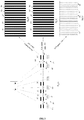
- Fig. 3 shows a schematic diagram of operation of the display panel 144, a first barrier panel 164a and a second barrier panel 166a in a narrow-viewing-angle working state.
- Part (a) on the left side in Fig. 3 is a side view of the display panel 144, the first barrier panel 164a and the second barrier panel 166a.
- the first barrier panel 164a is positioned above the display panel, and the second barrier panel 166a is positioned above the first barrier panel 164a.
- Part (b) on the right upper side in Fig. 3 is a front view of the second barrier panel 166a.
- Part (c) on the right middle side in Fig. 3 is a front view of the first barrier panel 164a.
- Part (d) on the right lower side in Fig. 3 is a front view of the display panel 144.
- control unit 120 sends an image frame to the display driving unit 142, and sends a barrier control instruction to the barrier driving unit 162.
- the display driving unit 142 is configured to drive the display panel 144 to display the image frame in a plurality of display regions 143 which are arranged in parallel at intervals, and each display region 143 is configured to display a part of displayed contents in the image frame respectively.
- each display region is configured to display 1/N of the image frame, and the size of the displayed content displayed on each display region is the same or different.
- a union of the displayed contents displayed by all the display regions 143 is the same as the complete image frame.
- the image frame is split into multiple strip-type displayed contents.
- the number of split strips is the same as the number of the display regions, and each displayed content is displayed respectively in each display region 143.
- Each display region 143 is a rectangular strip-type display region.
- An idle region 145 between every two adjacent display regions 143 may not display any content.
- all the display regions 143 have the same lengths and widths.
- the length of each display region 143 is 1,080 pixels, and the width is 5 pixels.
- a width of the idle region 145 between every two adjacent display regions 143 is also the same.
- the width of each idle region 145 is 3 pixels.
- the display regions 143 positioned in a central region of the display panel 144 are wider than the display regions 143 positioned in an edge region of the display panel 144.
- the widths of the idle regions 145 positioned in the central region of the display panel 144 are more than the widths of the idle regions 145 positioned in the edge region of the display panel 144. No restrictive is made in the embodiment.
- the barrier driving unit 162 is configured to control the first barrier panel 164a to form the first barriers 163 in a plurality of first barrier regions which are arranged in parallel at intervals according to the barrier control instruction.
- the first barriers are parallax barriers which are lightproof or which have lower light transmittance than the predetermined condition. The first barriers can block the displayed contents positioned below the first barriers.
- each first barrier 163 has the same length and width with each other.
- the length of each first barrier 163 is 1,080 pixels, and the width is 2 pixels.
- a width of the first light transmission region 165 between every two adjacent first barriers 163 is also the same.
- the width of each first light transmission region 165 is 3 pixels.
- the first barriers 163 positioned in a central region of the first barrier panel 164 are wider than the first barriers 163 positioned in an edge region of the first barrier panel 164.
- the widths of the first light transmission regions 165 positioned in the central region of the first barrier panel 164 are more than the widths of the first light transmission regions 165 positioned in the edge region of the first barrier panel 164. No restrictive is made in the embodiment.
- the barrier driving unit 162 is further configured to control the second barrier panel 166a to form the second barriers 167 in a plurality of second barrier regions which are arranged in parallel at intervals according to the barrier control instruction.
- the second barriers are parallax barriers which are lightproof or which have lower light transmittance than the predetermined condition. The second barriers can block the displayed contents positioned below the second barriers.
- each second barrier 167 has the same length and width with each other.
- the length of each second barrier 167 is 1,080 pixels, and the width is 2 pixels.
- a width of the second light transmission region 168 between every two adjacent second barriers 167 is also the same.
- the width of each second light transmission region 168 is 3 pixels.
- the widths of the second barriers 167 positioned in a central region of the second barrier panel 166 are more than the widths of the second barriers 167 positioned in an edge region of the second barrier panel 166.
- the widths of the second light transmission regions 168 positioned in the central region of the second barrier panel 166 are more than the widths of the second light transmission regions 168 positioned in the edge region of the second barrier panel 166. There are no limits made in the embodiment.
- a first light transmission region b2 of the first barrier panel 164 is positioned directly over a display region a1 in the display panel 144.
- the first light transmission region b2 is formed between two adjacent first barriers (a first barrier b1 and a first barrier b3).
- a second light transmission region c2 of the second barrier panel 166 is positioned directly over the first light transmission region b2.
- the second light transmission region c2 is formed between two adjacent second barriers (a second barrier c1 and a second barrier c3).
- a displayed content displayed on the display region a1 is emitted to a predetermined visible range through the first light transmission region b2 and the second light transmission region c2 corresponding to the display region al.
- each first barrier 163 and the corresponding second barrier 167 have the same length and width.
- a first barrier 163 has a length of 1,080 pixels and a width of 2 pixels
- the corresponding second barrier 167 also has the length of 1,080 pixels and the width of 2 pixels.
- Each first light transmission region 165 and the corresponding second light transmission region 168 also have the same width.
- a first light transmission region 165 has a width of 3 pixels
- the corresponding second light transmission region 168 also has the width of 3 pixels.
- first barrier 163 with the same length but different widths with the corresponding second barrier 167.
- widths of the first barriers 163 positioned in the central region of the first barrier panel 164 are more than the widths of the second barriers 167 positioned in the central region of the second barrier panel 166.
- first light transmission region 165 with the same length but different widths, compared with the corresponding second light transmission region 168.
- widths of the first light transmission regions 165 positioned in the central region of the first barrier panel 164 are more than the widths of the second light transmission regions 168 positioned in the central region of the second barrier panel 166.
- the displayed content respectively displayed by each display region 143 is emitted to the predetermined visible range through the corresponding first light transmission region 165 and second light transmission region 168. That is, when being displayed through the display device 100, the image frame 10 may be split into multiple displayed contents for displaying.
- a front view of a final display picture 20 may be schematically shown in Fig. 4 .
- the width of the display barrier between every two adjacent displayed contents is relatively small, so that influence of a final display effect observed by eyes of a user can be reduced as much as possible.
- a left side in Fig. 5 is a first direction and a right side is a second direction.
- Each display region 143 has an edge a in the first direction, and has an edge b in the second direction.
- There are two corresponding first barriers 163 above each display region 143 wherein one first barrier 163 has an edge c in the second direction, and the other first barrier 163 has an edge d in the first direction.
- the predetermined visible range has an edge g in the first direction, and has an edge h in the second direction.
- each edge meets a first rule: the edge a, the edge c and the edge g are positioned on the same plane, and the edge b, the edge f and the edge h are positioned on the same plane, thereby ensuring that the displayed content in each display region 143 may only be completely viewed within the predetermined visible range.
- the display region 143 positioned on an outermost edge may have a design different from that in Fig. 5 .
- the display region 143 positioned on the outermost edge is replaced with an idle region.
- each edge meets a second rule: the edge a, the edge e and the edge g are positioned on the same plane, and the edge b, the edge d and the edge h are positioned on the same plane, thereby ensuring that the displayed content in each display region 143 may only be completely viewed within the predetermined visible range.
- the display region 143 positioned on the outermost edge may have a design different from that in Fig. 5 .
- the display region 143 positioned on the outermost edge is replaced with an idle region.
- the predetermined visible range is a region for the eyes of the user to view, so that a width of the predetermined visible range is set according to an ocular distance between eyes, the width ef being usually slightly more than the ocular distance between the eyes. That is, the predetermined visible range is a range which is set according to the ocular distance between the eyes.
- positions of the display regions 143 on the display panel 144 are fixed, positions of the first barriers 163 on the first barrier panel 164 are fixed, and positions of the second barriers 167 on the second barrier panel 166 are fixed. That is, the predetermined visible range is fixed.
- the display driving unit 142 is configured to determine the positions of the plurality of display regions 143 which are arranged in parallel at intervals on the display panel 144 according to pre-stored first position information, split the image frame to obtain the displayed content corresponding to each display region 143 and drive each display region 143 to display the respectively corresponding displayed content according to the positions of the plurality of display regions 143.
- the barrier driving unit 162 is configured to determine the positions of the plurality of first barrier regions which are arranged in parallel at intervals on the first barrier panel 164 according to pre-stored second position information, and drive each of the plurality of first barrier regions to form the respectively corresponding first barrier 164 according to the positions of the plurality of first barrier regions.
- the barrier driving unit 162 is configured to determine the positions of the plurality of second barrier regions which are arranged in parallel at intervals on the second barrier panel according to pre-stored third position information, and drive each of the plurality of second barrier regions to form the respectively corresponding second barrier 167 according to the positions of the plurality of second barrier regions.
- positions of the eyes are variable, and distances G between the eyes and the display panel 144 are variable, so that the predetermined visible range is variable.
- the control unit 120 is further configured to send a first position determination instruction to the display driving unit 142.
- the display driving unit 142 is configured to determine the positions of the plurality of display regions 143 which are arranged in parallel at intervals on the display panel 144 according to the first position determination instruction, split the image frame to obtain the displayed content corresponding to each display region 143 and drive each display region 143 to display the respectively corresponding displayed content according to the positions of the plurality of display regions 143.
- control unit 120 is further configured to send a second position determination instruction to the barrier driving unit 162.
- the barrier driving unit 162 is configured to determine the positions of the plurality of first barrier regions which are arranged in parallel at intervals on the first barrier panel 164 according to the second position determination instruction, and drive each of the plurality of first barrier regions to form the respectively corresponding first barrier 163 according to the positions of the plurality of first barrier regions.
- control unit 120 is further configured to send a third position determination instruction to the barrier driving unit 162.
- the barrier driving unit 162 is configured to determine the positions of the plurality of second barrier regions which are arranged in parallel at intervals on the second barrier panel according to the third position determination instruction, and drive each of the plurality of second barrier regions to form the respectively corresponding second barrier 167 according to the positions of the plurality of second barrier regions.
- the first position determination instruction is configured to indicate the position of each display region 143.
- the second position determination instruction is configured to indicate the position of each of the plurality of first barrier regions.
- the third position determination instruction is configured to indicate the position of each of the plurality of second barrier regions.
- the control unit 120 dynamically determines the position of each first barrier 163 according to the ocular distance ef between the eyes, projection coordinates of the eyes on the display panel 144, the distances between the eyes and the display panel 144 and a distance L between image display surfaces of the first barrier panel 164 and the display panel 144 and according to a rule shown in Fig. 6 .
- the control unit 120 dynamically determines the position of each display region 143 according to the ocular distance ef between the eyes, projection coordinates of the eyes on the second barrier panel 166, distances G between the eyes and the second barrier panel 166 and a distance L between the first barrier panel 164 and the display panel 144 and according to a rule shown in Fig. 5 .
- a manner of the control unit 120 acquiring the ocular distance ef of the eyes, the projection coordinates of the eyes on the second barrier panel 166, the distances G between the eyes and the second barrier panel 166 and the distance L between the first barrier panel 164 and the display panel 144 is not limited.
- the control unit 120 may acquire these parameters through a device such as a front camera and a distance sensor.
- control unit is configured to send an image frame to the display driving unit; and the display driving unit is configured to drive the display panel to display the image frame in a plurality of display regions which are arranged in parallel at intervals, each of the plurality of display regions being configured to display a part of displayed contents in the image frame respectively, wherein the displayed content respectively displayed by each of the plurality of display regions is emitted to the predetermined visible range through the first light transmission region and second light transmission region corresponding to the display region.
- the display device 100 has two working modes: a wide-viewing-angle working mode and a narrow-viewing-angle working mode.
- the display device 100 may be switched between the two working modes.
- the control unit 120 sends a first state switching instruction to the display driving unit 142 and the barrier driving unit 162.
- the display driving unit 142 and the barrier driving unit 162 work according to the above working mode.
- the control unit 120 sends a second state switching indication to the display driving unit 142 and the barrier driving unit 162.
- the display driving unit 142 is configured to drive the display panel 142 to display the image frame in the whole display regions after receiving the second state switching indication, i.e. a conventional working mode.
- the barrier driving unit 162 is configured to drive the first barrier panel to cancel formation of the first barriers and drive the second barrier panel to cancel formation of the second barriers after receiving the second state switching indication, that is, the whole first barrier panel and the whole second barrier panel are both positioned in a transparent state or a semi-transparent state in which the light transmittance is higher than a predetermined value.
- two optional working modes are provided, so that display requirements of the user in different using places may be met.
- the idle region 145 between every two adjacent display regions 143 in the display panel 144 may display a predetermined disguised displayed content, the disguised displayed content referring to a displayed content viewed in a range outside the predetermined visible range.
- the disguised displayed content may disguise the image frame displayed in the display regions 143. For example, if the image frame is a game picture and the disguised displayed content is a webpage picture, then the game picture is viewed within the predetermined visible range, but the webpage picture is viewed in the range outside the predetermined visible range.
- the below is a method embodiment of the present invention, which may be configured to execute the device embodiment of the present invention. Details not described in the method embodiment of the present invention may refer to the device embodiment of the present invention.
- Fig. 6 is a flow chart showing a display method according to an exemplary embodiment. The method is applied to the display device provided by the embodiment shown in Fig. 1 or Fig. 2 , the display device including: a control unit, a display driving unit connected with the control unit, a display panel connected with the display driving unit, a first barrier panel positioned above the display panel and a second barrier panel positioned above the first barrier panel, wherein a plurality of first barriers which are arranged in parallel at intervals are distributed in the first barrier panel, and a first light transmission region is formed between every two adjacent first barriers; and a plurality of second barriers which are arranged in parallel at intervals are distributed in the second barrier panel, and a second light transmission region is formed between every two adjacent second barriers.
- the method provided by the embodiment may include the following steps.
- Step 601 the control unit sends an image frame to the display driving unit.
- the display driving unit drives the display panel to display the image frame in a plurality of display regions which are arranged in parallel at intervals, each of the plurality of display regions being configured to display a part of displayed contents in the image frame respectively.
- the displayed content respectively displayed by each of the plurality of display regions may be emitted to a predetermined visible range through the first light transmission region and second light transmission region corresponding to the display region.
- the control unit sends an image frame to the display driving unit, and the display driving unit drives the display panel to display the image frame on the plurality of display regions which are arranged in parallel at intervals, each of the plurality of display regions being configured to display a part of displayed contents in the image frame respectively, wherein the displayed content respectively displayed by each of the plurality of display regions is emitted to the predetermined visible range through the first light transmission region and the second light transmission region corresponding to the display region. Therefore, others around a user cannot easily view contents on a display screen and thus leakage of privacy of the user is avoided when the display screen is a wide-viewing-angle display screen.
- a visible range of the display panel can be limited within the predetermined visible range, and thus the image frame on the display panel cannot be viewed or completely viewed outside the predetermined visible range.
- the method includes the following steps.
- Step 701 the control unit sends an image frame to the display driving unit.
- a display stream usually includes an image frame sequence formed by multiple image frames, so that the step may be periodically executed for many times, or executed when the image frame changes.
- control unit executes the step once every 1/24 second.
- the display driving unit drives the display panel to display the image frame in a plurality of display regions which are arranged in parallel at intervals, each of the plurality of display regions being configured to display a part of displayed contents in the image frame respectively.
- the step is replaced with the following steps:
- control unit also sends a first position determination instruction to the display driving unit, the first position determination instruction being configured to indicate the position of each display region.
- first position determination instruction being configured to indicate the position of each display region.
- first barrier panel is a film material on which a plurality of first barriers arranged in parallel at intervals are distributed and the second barrier panel is a film material on which a plurality of second barriers arranged in parallel at intervals are distributed.
- the display device further includes a barrier driving unit.
- the barrier driving unit is connected with the control unit, the first barrier panel and the second barrier panel respectively.
- the display method further includes the following steps.
- Step 703 the control unit sends a barrier control instruction to the barrier driving unit.
- the barrier driving unit controls the first barrier panel to form the first barriers in a plurality of first barrier regions which are arranged in parallel at intervals according to the barrier control instruction.
- the step may be replaced with the following steps:
- the barrier driving unit determines positions of the plurality of first barrier regions which are arranged in parallel at intervals on the first barrier panel according to pre-stored second position information;
- the barrier driving unit drives each first barrier region to form the respectively corresponding first barrier according to the positions of the plurality of first barrier regions.
- control unit further sends a second position determination instruction to the barrier driving unit, the second position determination instruction being configured to indicate the position of each first barrier.
- the step may be replaced with the following steps:
- the displayed content respectively displayed by each display region is emitted to a predetermined visible range by the light which is emitted by a backlight source and transmitted through a first light transmission region between every two adjacent first barriers on the first barrier panel.
- the predetermined visible range is a range determined according to an ocular distance between eyes of a person.
- Step 705 the barrier driving unit controls the second barrier panel to form the second barriers in a plurality of second barrier regions which are arranged in parallel at intervals according to the barrier control instruction.
- the step may be replaced with the following steps:
- control unit further sends a third position determination instruction to the barrier driving unit, the third position determination instruction being configured to indicate the position of each second barrier.
- the step may be replaced with the following steps:
- the displayed content respectively displayed by each of the plurality of display regions is emitted to the predetermined visible range through the first light transmission region and the second light transmission region corresponding to the display region.
- the predetermined visible range is the range determined according to the ocular distance between the eyes of a person.
- Steps 701-702 are executed in parallel with Steps 703-705.
- a narrow-viewing-angle working state may be switched to a wide-viewing-angle working state through the following Steps 706-708.
- Step 706 the control unit sends a state switching indication to the display driving unit and the barrier driving unit when a working state is switched from a narrow-viewing-angle working state to a wide-viewing-angle working state.
- Step 707 the display driving unit drives the display panel to display the image frame in the whole display regions after receiving the state switching indication.
- the barrier driving unit drives the first barrier panel to cancel formation of the first barriers and drives the second barrier panel to cancel formation of the second barriers after receiving the state switching indication.
- Step 707 and Step 708 are steps which may be executed in parallel.
- Step 701 to Step 708 a process executed when the working state is switched from the wide-viewing-angle working state to the narrow-viewing-angle working state is an inverse process of Step 701 to Step 708, which is apparent to those skilled in the art with reference to the descriptions of Steps 701 to 708 and to the descriptions in the above device embodiment, and thus will not be elaborated herein.
- the display driving unit drives an idle region between every two adjacent display regions on the display panel to enter a non-working state or the display driving unit drives the idle region on the display panel to display a predetermined disguised displayed content when the working state is the narrow-viewing-angle working state.
Landscapes
- Physics & Mathematics (AREA)
- Engineering & Computer Science (AREA)
- General Physics & Mathematics (AREA)
- Theoretical Computer Science (AREA)
- Computer Hardware Design (AREA)
- Chemical & Material Sciences (AREA)
- Crystallography & Structural Chemistry (AREA)
- Nonlinear Science (AREA)
- Signal Processing (AREA)
- Multimedia (AREA)
- Mathematical Physics (AREA)
- Optics & Photonics (AREA)
- Devices For Indicating Variable Information By Combining Individual Elements (AREA)
Abstract
Description
- The present invention generally relates to the technical field of display, and more particularly, to a display device and a display method.
- A display screen is one of the most common input and output devices on electronic equipment. A display screen has a capability of displaying text information, image information and video information.
- At present, a display screen is usually a wide-viewing-angle display screen, and a viewing angle approximately ranges from 120° to 170°. When a user uses electronic equipment in a crowded place such as on a bus and a metro, others around the user can easily view contents on a display screen, thereby causing leakage of privacy of the user.
- Accordingly, the present invention provides a display device and a display method, in accordance with claims which follow.
- According to a first aspect of the present invention, a display device is provided. The display device may include: a control unit, a display driving unit connected with the control unit, a display panel connected with the display driving unit, a first barrier panel positioned above the display panel and a second barrier panel positioned above the first barrier panel. A plurality of first barriers which are arranged in parallel at intervals may be distributed in the first barrier panel, and a first light transmission region may be formed between every two adjacent first barriers. A plurality of second barriers which are arranged in parallel at intervals may be distributed in the second barrier panel, and a second light transmission region may be formed between every two adjacent second barriers.
The control unit may be configured to send an image frame to the display driving unit. The display driving unit may be configured to drive the display panel to display the image frame in a plurality of display regions which are arranged in parallel at intervals, each of the plurality of display regions being configured to display a part of displayed contents in the image frame respectively, wherein the part of the displayed contents respectively displayed by each of the plurality of display regions may be emitted to a predetermined visible range through the first light transmission region and the second light transmission region which are corresponding to the display region. - Optionally, the display driving unit may be configured to determine positions of the plurality of display regions which are arranged in parallel at intervals on the display panel according to pre-stored first position information, split the image frame to obtain the part of the displayed contents corresponding to each of the plurality of display regions and drive each of the plurality of display regions to display the respectively corresponding part of the displayed contents according to the positions of the plurality of display regions. Or, the control unit may further be configured to send a first position determination instruction to the display driving unit; and the display driving unit may be configured to determine positions of the plurality of display regions which are arranged in parallel at intervals on the display panel according to the first position determination instruction, split the image frame to obtain the part of the displayed contents corresponding to each of the plurality of display regions and drive each of the plurality of display regions to display the respectively corresponding part of the displayed contents according to the positions of the plurality of display regions.
- Optionally, the display device may further include a barrier driving unit; the barrier driving unit may be connected with the control unit, the first barrier panel and the second barrier panel respectively. The control unit may further be configured to send a barrier control instruction to the barrier driving unit; and the barrier driving unit may be configured to, according to the barrier control instruction, control the first barrier panel to form the plurality of first barriers in a plurality of first barrier regions which are arranged in parallel at intervals and control the second barrier panel to form the plurality of second barriers in a plurality of second barrier regions which are arranged in parallel at intervals according to the barrier control instruction.
- Optionally, the barrier driving unit may be configured to determine positions of the plurality of first barrier regions which are arranged in parallel at intervals on the first barrier panel according to pre-stored second position information, and drive each of the plurality of first barrier regions to form the respectively corresponding first barrier according to the positions of the plurality of first barrier regions; or, the control unit may further be configured to send a second position determination instruction to the barrier driving unit, and the barrier driving unit may be configured to determine positions of the plurality of first barrier regions which are arranged in parallel at intervals on the first barrier panel according to the second position determination instruction, and drive each of the plurality of first barrier regions to form the respectively corresponding first barrier according to the positions of the plurality of first barrier regions.
- Optionally, the barrier driving unit may be configured to determine positions of the plurality of second barrier regions which are arranged in parallel at intervals on the second barrier panel according to pre-stored third position information, and drive each of the plurality of second barrier regions to form the respectively corresponding second barrier according to the positions of the plurality of first barrier regions; or, the control unit may further be configured to send a third position determination instruction to the barrier driving unit, and the barrier driving unit may be configured to determine positions of the plurality of second barrier regions which are arranged in parallel at intervals on the second barrier panel according to the third position determination instruction, and drive each of the plurality of second barrier regions to form the respectively corresponding second barrier according to the positions of the plurality of second barrier regions.
- Optionally, the control unit may further be configured to send a state switching indication to the display driving unit and the barrier driving unit when a working state is switched from a narrow-viewing-angle working state to a wide-viewing-angle working state; the display driving unit may be configured to drive the display panel to display the image frame on the plurality of display regions after receiving the state switching indication; and the barrier driving unit may be configured to drive the first barrier panel to cancel formation of the plurality of first barriers and drive the second barrier panel to cancel formation of the plurality of second barriers after receiving the state switching indication.
- Optionally, the first barrier panel may be a film material on which the plurality of first barriers arranged in parallel at intervals are distributed, and the second barrier panel may be a film material on which the plurality of second barriers arranged in parallel at intervals are distributed.
- Optionally, the predetermined visible range may be a range determined according to an ocular distance between human eyes.
- Optionally, the display driving unit may further be configured to drive an idle region between every two adjacent display regions on the display panel to enter a non-working state, or, drive an idle region between every two adjacent display regions on the display panel to display a predetermined disguised displayed content.
- According to a second aspect of the present invention, a display method is provided. The display method may be applied to a display device, the display device including: a control unit, a display driving unit connected with the control unit, a display panel connected with the display driving unit, a first barrier panel positioned above the display panel and a second barrier panel positioned above the first barrier panel. A plurality of first barriers which are arranged in parallel at intervals may be distributed in the first barrier panel, and a first light transmission region may be formed between every two adjacent first barriers. A plurality of second barriers which are arranged in parallel at intervals may be distributed in the second barrier panel, and a second light transmission region may be formed between every two adjacent second barriers. The method may include: sending, by the control unit, an image frame to the display driving unit; and driving, by the display driving unit, the display panel to display the image frame in a plurality of display regions which are arranged in parallel at intervals, each of the plurality of display regions being configured to display a part of displayed contents in the image frame respectively, wherein the part of the displayed contents respectively displayed by each of the plurality of display regions may be emitted to a predetermined visible range through the first light transmission region and the second light transmission region which are corresponding to the display region.
- Optionally, the step of driving, by the display driving unit, the display panel to display the image frame on the plurality of display regions which are arranged in parallel at intervals may include:
- determining, by the display driving unit, positions of the plurality of display regions which are arranged in parallel at intervals on the display panel according to pre-stored first position information, splits the image frame to obtain the part of the displayed contents corresponding to each of the plurality of display regions, and driving each of the plurality of display regions to display the respectively corresponding part of the displayed contents according to the positions of the plurality of display regions; or,
- receiving, by the display driving unit, a first position determination instruction from the control unit, determining positions of the plurality of display regions which are arranged in parallel at intervals on the display panel according to the first position determination instruction, splits the image frame to obtain the part of the displayed contents corresponding to each of the plurality of display regions, and driving each of the plurality of display regions to display the respectively corresponding part of the displayed contents according to the positions of the plurality of display regions.
- Optionally, the display device may further include a barrier driving unit. The barrier driving unit may be connected with the control unit, the first barrier panel and the second barrier panel respectively. The method may further include: sending, by the control unit, a barrier control instruction to the barrier driving unit; and controlling, by the barrier driving unit, the first barrier panel to form the plurality of first barriers in a plurality of first barrier regions which are arranged in parallel at intervals and controlling the second barrier panel to form the plurality of second barriers in a plurality of second barrier regions which are arranged in parallel at intervals according to the barrier control instruction.
- Optionally, the step that controlling, by the barrier driving unit, the first barrier panel to form the plurality of first barriers in the plurality of first barrier regions which are arranged in parallel at intervals according to the barrier control instruction may include:
- determining, by the barrier driving unit, positions of the plurality of first barrier regions which are arranged in parallel at intervals on the first barrier panel according to pre-stored second position information, and drives each of the plurality of first barrier regions to form the respectively corresponding first barrier according to the positions of the plurality of first barrier regions; or,
- sending, by the control unit, a second position determination instruction to the barrier driving unit; and determining, by the barrier driving unit, positions of the plurality of first barrier regions which are arranged in parallel at intervals on the first barrier panel according to the second position determination instruction, and drives each of the plurality of first barrier regions to form the respectively corresponding first barrier according to the positions of the plurality of first barrier regions.
- Optionally, the step of controlling, by the barrier driving unit, the second barrier panel to form the of the plurality of second barriers in the plurality of second barrier regions which are arranged in parallel at intervals according to the barrier control instruction may include:
- determining, by the barrier driving unit, positions of the plurality of second barrier regions which are arranged in parallel at intervals on the second barrier panel according to pre-stored third position information, and driving each of the plurality of second barrier regions to form the respectively corresponding second barrier according to the positions of the plurality of second barrier regions; or,
- sending, by the control unit, a third position determination instruction to the barrier driving unit; and determining, by the barrier driving unit, positions of the plurality of second barrier regions which are arranged in parallel at intervals on the second barrier panel according to the third position determination instruction, and drives each of the plurality of second barrier regions to form the respectively corresponding second barrier according to the positions of the plurality of second barrier regions.
- Optionally, the method may further include:
- sending, by the control unit, a state switching indication to the display driving unit and the barrier driving unit when a working state is switched from a narrow-viewing-angle working state to a wide-viewing-angle working state;
- driving, by the display driving unit, the display panel to display the image frame on the plurality of display regions after receiving the state switching indication; and
- driving, by the barrier driving unit, the first barrier panel to cancel formation of the plurality of first barriers and driving the second barrier panel to cancel formation of the plurality of second barriers after receiving the state switching indication.
- Optionally, the first barrier panel may be a film material on which the plurality of first barriers arranged in parallel at intervals are distributed, and the second barrier panel may be a film material on which the plurality of second barriers arranged in parallel at intervals are distributed.
- Optionally, the predetermined visible range may be a range determined according to an ocular distance between human eyes.
- Optionally, the method may further include:
- driving, by the display driving unit, an idle region between every two adjacent display regions on the display panel to enter a non-working state; or,
- driving, by the display driving unit, an idle region between every two adjacent display regions on the display panel to display a predetermined disguised displayed content.
- In one particular embodiment, the steps of the display method are determined by computer program instructions.
- Consequently, according to a third aspect, the invention is also directed to a computer program for executing the steps of a display method as described above when this program is executed by a computer.
- This program can use any programming language and take the form of source code, object code or a code intermediate between source code and object code, such as a partially compiled form, or any other desirable form.
- The invention is also directed to a computer-readable information medium containing instructions of a computer program as described above.
- The information medium can be any entity or device capable of storing the program. For example, the support can include storage means such as a ROM, for example a CD ROM or a microelectronic circuit ROM, or magnetic storage means, for example a diskette (floppy disk) or a hard disk.
- Alternatively, the information medium can be an integrated circuit in which the program is incorporated, the circuit being adapted to execute the method in question or to be used in its execution.
- The technical solutions provided by the embodiments of the present invention may achieve the following beneficial effects.
- The control unit is configured to send an image frame to the display driving unit. The display driving unit is configured to drive the display panel to display the image frame in a plurality of display regions which are arranged in parallel at intervals, each of the plurality of display regions being configured to display a part of displayed contents in the image frame respectively, wherein the displayed content respectively displayed by each of the plurality of display regions is emitted to the predetermined visible range through the first light transmission region and the second light transmission region which are corresponding to the display regions. Therefore, the problem that others around a user can easily view contents on a display screen to cause leakage of privacy of the user when the display screen is a wide-viewing-angle display screen can be solved. Accordingly, a visible range of the display panel can be limited within the predetermined visible range, and thus the image frame on the display panel cannot be viewed or completely viewed outside the predetermined visible range.
- It is to be understood that the above general descriptions and detailed descriptions below are only exemplary and explanatory and are not restrictive of the invention, as claimed.
- The accompanying drawings, which are incorporated in and constitute a part of this specification, illustrate embodiments consistent with the invention and, together with the description, serve to explain the principles of the invention.
-
Fig. 1 is a block diagram of a display device according to an exemplary embodiment; -
Fig. 2 is a block diagram of a display device according to another exemplary embodiment; -
Fig. 3 consisting ofFig. 3A, Fig. 3B, Fig.3C and Fig. 3D is a schematic diagram of operation of the display device according to an embodiment as shown inFig. 1 ; -
Fig. 4 is a schematic diagram illustrating an effect when an image frame is displayed in the display device according to an embodiment as shown inFig. 1 ; -
Fig. 5 is a schematic diagram of the principle of the display device according to an embodiment as shown inFig. 1 ; -
Fig. 6 is a flow chart showing a display method according to an exemplary embodiment; and -
Fig. 7 is a flow chart showing a display method according to another exemplary embodiment. - Reference will now be made in detail to exemplary embodiments, examples of which are illustrated in the accompanying drawings. The following description refers to the accompanying drawings in which the same numbers in different drawings represent the same or similar elements unless otherwise represented. The implementations set forth in the following description of exemplary embodiments do not represent all implementations matched with the present invention. Instead, they are merely examples of apparatuses and methods matched with aspects related to the present invention as recited in the appended claims.
- Certain terms used in the present disclosure are only intended to describe specific aspects, but are not intended to limit the present disclosure. For example, singular form words "a," "said," and "the" used in the present disclosure and the appended claims are intended to include plural form, unless otherwise clearly stated. Also, the term "and/or" used herein refers to any or all combinations of one or more listed related items. The word "if' used here may be interpreted as "at the moment when..." or "when..." or "in response to confirmation".
- It is to be noted that although the flowcharts in some exemplary aspects describe each step as a sequenced process, a variety of steps therein may be implemented in parallel, concurrently or simultaneously. In addition, the sequence of all steps may be re-arranged. When the operation is completed, the process may be ended, but additional steps not included in the accompanying drawings may be executed. The process may correspond to a method, a function, a regulation, a sub-routine, a sub-program and the like.
- The embodiments of the present invention provide a display device with a relatively narrow viewing angle and a display method. Optionally, the display device may also be switched between a wide-viewing-angle mode and a narrow-viewing-angle mode, wherein the display device may be any electronic device with a display screen, such as a mobile phone and a tablet computer.
-
Fig. 1 is a block diagram of adisplay device 100 according to an exemplary embodiment. Thedisplay device 100 may implement narrow-viewing-angle display by virtue of a parallax barrier method. As shown inFig. 1 , thedisplay device 100 includes: acontrol unit 120, adisplay driving unit 142 connected with thecontrol unit 120, adisplay panel 144 connected with thedisplay driving unit 142, afirst barrier panel 164 arranged above thedisplay panel 144 and asecond barrier panel 166 positioned above thefirst barrier panel 164. - The
control unit 120 may be a processor or a graphics processor. Thecontrol unit 120 has capabilities of outputting an image frame and sending a control instruction. - The
display driving unit 142 includes a driving circuit and is configured to drive thedisplay panel 144 for displaying. Thedisplay panel 144 may be a Liquid Crystal Display (LCD) panel or an Organic Light-Emitting Display (OLED) panel. Optionally, when thedisplay panel 144 is an LCD panel, thedisplay device 100 further includes a backlight source positioned below the LCD panel. - A plurality of first barriers which are arranged in parallel at intervals are distributed in the
first barrier panel 164, and displayed contents positioned below the first barriers may be blocked by the first barriers on thefirst barrier panel 164. A plurality of second barriers which are arranged in parallel at intervals are distributed in thesecond barrier panel 166, and displayed contents positioned below the second barriers may be blocked by the second barriers on thesecond barrier panel 166. - A distance between the
first barrier panel 164 and thesecond barrier panel 166 may be preset. - It is to note that the
first barrier panel 164 may be a film material on which the plurality of first barriers arranged in parallel at intervals are distributed. The first barriers on thefirst barrier panel 164 have relatively poor light transmittance. The first barriers may be made of a material which is semitransparent or nontransparent or of which opaqueness is higher than a first threshold value. A region between every two adjacent first barriers is a first light transmission region, and the first light transmission region has relatively high light transmittance. For example, the light transmittance of the first light transmission region is higher than a second threshold value, and the second threshold value is, for example, 80%. When thefirst barrier panel 164 is made of the film material, a width and position of each first barrier may be designed according to a practical requirement, which will not be limited in the embodiment. - It is also to note that the
second barrier panel 166 may be a film material on which the plurality of second barriers arranged in parallel at intervals are distributed. The second barriers on thesecond barrier panel 166 have relatively poor light transmittance, and the second barriers may be made of a material which is semitransparent or nontransparent or of which opaqueness is higher than a second threshold value. A region between every two adjacent second barriers is a second light transmission region, and the second light transmission region has relatively high light transmittance. For example, the light transmittance of the second light transmission region is higher than the second threshold value, and the second threshold value is, for example, 80%. When thesecond barrier panel 166 is made of the film material, a width and position of each second barrier may be designed according to a practical requirement, which will not be limited in the embodiment. - Optionally, in the display device shown in
Fig. 1 , the first barrier panel and the second barrier panel both may be film materials which are lightproof or which have lower light transmittance than a predetermined condition. - According to another possible implementation mode, both the first barrier panel and the second barrier panel are panels with variable light transmittance, and the light transmittance is controlled by an electric signal. As shown in
Fig. 2 , thedisplay device 100 further includes abarrier driving unit 162. Thebarrier driving unit 162 is connected with thecontrol unit 120, thefirst barrier panel 164 and thesecond barrier panel 166 respectively. Thebarrier driving unit 162 includes a barrier driving circuit. The barrier driving circuit is also one of driving circuits, and is configured to drive the first barrier panel to form the first barriers and drive the second barrier panel to form the second barriers. - Optionally, the
display device 100 further includes: two barrier driving units, i.e. a barrier driving unit 162a and a barrier driving unit 162b respectively. The barrier driving unit 162a is connected with thecontrol unit 120 and thefirst barrier panel 164 respectively. The barrier driving unit 162b is connected with thecontrol unit 120 and thesecond barrier panel 166 respectively. The barrier driving unit 162a includes a first barrier driving circuit. The first barrier driving circuit is also one of driving circuits, and is configured to drive the first barrier panel to form the first barriers. The barrier driving unit 162b includes a second barrier driving circuit. The second barrier driving circuit is one of the driving circuits, and is configured to drive the second barrier panel to form the second barriers. - Optionally, the first barriers and the second barriers are all parallax barriers which are lightproof or which have lower light transmittance than a predetermined condition. Schematically, when the first barrier panel and the second barrier panel are both LCD panels, the
barrier driving unit 162 drives liquid crystal molecules in the first barrier panel to become twisted to form the first barriers, and thebarrier driving unit 162 drives liquid crystal molecules in the second barrier panel to become twisted to form the second barriers. - With reference to
Fig. 3 , which shows a schematic diagram of operation of thedisplay panel 144, a first barrier panel 164a and a second barrier panel 166a in a narrow-viewing-angle working state. Part (a) on the left side inFig. 3 is a side view of thedisplay panel 144, the first barrier panel 164a and the second barrier panel 166a. The first barrier panel 164a is positioned above the display panel, and the second barrier panel 166a is positioned above the first barrier panel 164a. Part (b) on the right upper side inFig. 3 is a front view of the second barrier panel 166a. Part (c) on the right middle side inFig. 3 is a front view of the first barrier panel 164a. Part (d) on the right lower side inFig. 3 is a front view of thedisplay panel 144. - In the narrow-viewing-angle working state, the
control unit 120 sends an image frame to thedisplay driving unit 142, and sends a barrier control instruction to thebarrier driving unit 162. - The
display driving unit 142 is configured to drive thedisplay panel 144 to display the image frame in a plurality ofdisplay regions 143 which are arranged in parallel at intervals, and eachdisplay region 143 is configured to display a part of displayed contents in the image frame respectively. Optionally, if there are N display regions, each display region is configured to display 1/N of the image frame, and the size of the displayed content displayed on each display region is the same or different. A union of the displayed contents displayed by all thedisplay regions 143 is the same as the complete image frame. - In other words, the image frame is split into multiple strip-type displayed contents. The number of split strips is the same as the number of the display regions, and each displayed content is displayed respectively in each
display region 143. Eachdisplay region 143 is a rectangular strip-type display region. Anidle region 145 between every twoadjacent display regions 143 may not display any content. - In a possible implementation mode, all the
display regions 143 have the same lengths and widths. For example, the length of eachdisplay region 143 is 1,080 pixels, and the width is 5 pixels. A width of theidle region 145 between every twoadjacent display regions 143 is also the same. For example, the width of eachidle region 145 is 3 pixels. In another possible implementation mode, there are at least twodisplay regions 143 with the same length but different widths. For example, thedisplay regions 143 positioned in a central region of thedisplay panel 144 are wider than thedisplay regions 143 positioned in an edge region of thedisplay panel 144. There are at least twoidle regions 145 with the same length but different widths. For example, the widths of theidle regions 145 positioned in the central region of thedisplay panel 144 are more than the widths of theidle regions 145 positioned in the edge region of thedisplay panel 144. No restrictive is made in the embodiment. - The
barrier driving unit 162 is configured to control the first barrier panel 164a to form thefirst barriers 163 in a plurality of first barrier regions which are arranged in parallel at intervals according to the barrier control instruction. The first barriers are parallax barriers which are lightproof or which have lower light transmittance than the predetermined condition. The first barriers can block the displayed contents positioned below the first barriers. - In a possible implementation mode, each
first barrier 163 has the same length and width with each other. For example, the length of eachfirst barrier 163 is 1,080 pixels, and the width is 2 pixels. A width of the firstlight transmission region 165 between every two adjacentfirst barriers 163 is also the same. For example, the width of each firstlight transmission region 165 is 3 pixels. In another possible implementation mode, there are at least twofirst barriers 163 with the same length but different widths. For example, thefirst barriers 163 positioned in a central region of thefirst barrier panel 164 are wider than thefirst barriers 163 positioned in an edge region of thefirst barrier panel 164. There are at least two firstlight transmission regions 165 with the same length but different widths. For example, the widths of the firstlight transmission regions 165 positioned in the central region of thefirst barrier panel 164 are more than the widths of the firstlight transmission regions 165 positioned in the edge region of thefirst barrier panel 164. No restrictive is made in the embodiment. - The
barrier driving unit 162 is further configured to control the second barrier panel 166a to form thesecond barriers 167 in a plurality of second barrier regions which are arranged in parallel at intervals according to the barrier control instruction. The second barriers are parallax barriers which are lightproof or which have lower light transmittance than the predetermined condition. The second barriers can block the displayed contents positioned below the second barriers. - In a possible implementation mode, each
second barrier 167 has the same length and width with each other. For example, the length of eachsecond barrier 167 is 1,080 pixels, and the width is 2 pixels. A width of the secondlight transmission region 168 between every two adjacentsecond barriers 167 is also the same. For example, the width of each secondlight transmission region 168 is 3 pixels. In another possible implementation mode, there are at least twosecond barriers 167 with the same length but different widths. For example, the widths of thesecond barriers 167 positioned in a central region of thesecond barrier panel 166 are more than the widths of thesecond barriers 167 positioned in an edge region of thesecond barrier panel 166. There are at least two secondlight transmission regions 168 with the same length but different widths. For example, the widths of the secondlight transmission regions 168 positioned in the central region of thesecond barrier panel 166 are more than the widths of the secondlight transmission regions 168 positioned in the edge region of thesecond barrier panel 166. There are no limits made in the embodiment. - Optionally, a first light transmission region b2 of the
first barrier panel 164 is positioned directly over a display region a1 in thedisplay panel 144. The first light transmission region b2 is formed between two adjacent first barriers (a first barrier b1 and a first barrier b3). A second light transmission region c2 of thesecond barrier panel 166 is positioned directly over the first light transmission region b2. The second light transmission region c2 is formed between two adjacent second barriers (a second barrier c1 and a second barrier c3). A displayed content displayed on the display region a1 is emitted to a predetermined visible range through the first light transmission region b2 and the second light transmission region c2 corresponding to the display region al. - In a possible implementation mode, each
first barrier 163 and the correspondingsecond barrier 167 have the same length and width. For example, afirst barrier 163 has a length of 1,080 pixels and a width of 2 pixels, and the correspondingsecond barrier 167 also has the length of 1,080 pixels and the width of 2 pixels. Each firstlight transmission region 165 and the corresponding secondlight transmission region 168 also have the same width. For example, a firstlight transmission region 165 has a width of 3 pixels, and the corresponding secondlight transmission region 168 also has the width of 3 pixels. - In another possible implementation mode, there is at least one
first barrier 163 with the same length but different widths with the correspondingsecond barrier 167. For example, the widths of thefirst barriers 163 positioned in the central region of thefirst barrier panel 164 are more than the widths of thesecond barriers 167 positioned in the central region of thesecond barrier panel 166. There is at least one firstlight transmission region 165 with the same length but different widths, compared with the corresponding secondlight transmission region 168. For example, the widths of the firstlight transmission regions 165 positioned in the central region of thefirst barrier panel 164 are more than the widths of the secondlight transmission regions 168 positioned in the central region of thesecond barrier panel 166. There are no limits made in the embodiment. - The displayed content respectively displayed by each
display region 143 is emitted to the predetermined visible range through the corresponding firstlight transmission region 165 and secondlight transmission region 168. That is, when being displayed through thedisplay device 100, theimage frame 10 may be split into multiple displayed contents for displaying. A front view of afinal display picture 20 may be schematically shown inFig. 4 . In a practical using process, the width of the display barrier between every two adjacent displayed contents is relatively small, so that influence of a final display effect observed by eyes of a user can be reduced as much as possible. - With reference to
Fig. 5 , it is set that a left side inFig. 5 is a first direction and a right side is a second direction. Eachdisplay region 143 has an edge a in the first direction, and has an edge b in the second direction. There are two correspondingfirst barriers 163 above eachdisplay region 143, wherein onefirst barrier 163 has an edge c in the second direction, and the otherfirst barrier 163 has an edge d in the first direction. There are also two correspondingsecond barriers 167 above eachdisplay region 143, wherein asecond barrier 167 has an edge e in the second direction, and the othersecond barrier 167 has an edge f in the first direction. The predetermined visible range has an edge g in the first direction, and has an edge h in the second direction. - Optionally, for each
display region 143, when the edge a is on a left side of the edge c, each edge meets a first rule: the edge a, the edge c and the edge g are positioned on the same plane, and the edge b, the edge f and the edge h are positioned on the same plane, thereby ensuring that the displayed content in eachdisplay region 143 may only be completely viewed within the predetermined visible range. It is to note that thedisplay region 143 positioned on an outermost edge may have a design different from that inFig. 5 . For example, thedisplay region 143 positioned on the outermost edge is replaced with an idle region. - Optionally, for each
display region 143, when the edge a is on a right side of the edge c or the edge a and the edge c are positioned on the same straight line, each edge meets a second rule: the edge a, the edge e and the edge g are positioned on the same plane, and the edge b, the edge d and the edge h are positioned on the same plane, thereby ensuring that the displayed content in eachdisplay region 143 may only be completely viewed within the predetermined visible range. It is to note that thedisplay region 143 positioned on the outermost edge may have a design different from that inFig. 5 . For example, thedisplay region 143 positioned on the outermost edge is replaced with an idle region. - In addition, the predetermined visible range is a region for the eyes of the user to view, so that a width of the predetermined visible range is set according to an ocular distance between eyes, the width ef being usually slightly more than the ocular distance between the eyes. That is, the predetermined visible range is a range which is set according to the ocular distance between the eyes.
- In a possible implementation mode, positions of the
display regions 143 on thedisplay panel 144 are fixed, positions of thefirst barriers 163 on thefirst barrier panel 164 are fixed, and positions of thesecond barriers 167 on thesecond barrier panel 166 are fixed. That is, the predetermined visible range is fixed. In this case, thedisplay driving unit 142 is configured to determine the positions of the plurality ofdisplay regions 143 which are arranged in parallel at intervals on thedisplay panel 144 according to pre-stored first position information, split the image frame to obtain the displayed content corresponding to eachdisplay region 143 and drive eachdisplay region 143 to display the respectively corresponding displayed content according to the positions of the plurality ofdisplay regions 143. - Optionally, the
barrier driving unit 162 is configured to determine the positions of the plurality of first barrier regions which are arranged in parallel at intervals on thefirst barrier panel 164 according to pre-stored second position information, and drive each of the plurality of first barrier regions to form the respectively correspondingfirst barrier 164 according to the positions of the plurality of first barrier regions. - Optionally, the
barrier driving unit 162 is configured to determine the positions of the plurality of second barrier regions which are arranged in parallel at intervals on the second barrier panel according to pre-stored third position information, and drive each of the plurality of second barrier regions to form the respectively correspondingsecond barrier 167 according to the positions of the plurality of second barrier regions. - In another possible implementation mode, positions of the eyes are variable, and distances G between the eyes and the
display panel 144 are variable, so that the predetermined visible range is variable. In this case, thecontrol unit 120 is further configured to send a first position determination instruction to thedisplay driving unit 142. Thedisplay driving unit 142 is configured to determine the positions of the plurality ofdisplay regions 143 which are arranged in parallel at intervals on thedisplay panel 144 according to the first position determination instruction, split the image frame to obtain the displayed content corresponding to eachdisplay region 143 and drive eachdisplay region 143 to display the respectively corresponding displayed content according to the positions of the plurality ofdisplay regions 143. - Optionally, the
control unit 120 is further configured to send a second position determination instruction to thebarrier driving unit 162. Thebarrier driving unit 162 is configured to determine the positions of the plurality of first barrier regions which are arranged in parallel at intervals on thefirst barrier panel 164 according to the second position determination instruction, and drive each of the plurality of first barrier regions to form the respectively correspondingfirst barrier 163 according to the positions of the plurality of first barrier regions. - Optionally, the
control unit 120 is further configured to send a third position determination instruction to thebarrier driving unit 162. Thebarrier driving unit 162 is configured to determine the positions of the plurality of second barrier regions which are arranged in parallel at intervals on the second barrier panel according to the third position determination instruction, and drive each of the plurality of second barrier regions to form the respectively correspondingsecond barrier 167 according to the positions of the plurality of second barrier regions. - The first position determination instruction is configured to indicate the position of each
display region 143. The second position determination instruction is configured to indicate the position of each of the plurality of first barrier regions. The third position determination instruction is configured to indicate the position of each of the plurality of second barrier regions. - Optionally, when the position of each
display region 143 is fixed, thecontrol unit 120 dynamically determines the position of eachfirst barrier 163 according to the ocular distance ef between the eyes, projection coordinates of the eyes on thedisplay panel 144, the distances between the eyes and thedisplay panel 144 and a distance L between image display surfaces of thefirst barrier panel 164 and thedisplay panel 144 and according to a rule shown inFig. 6 . - Optionally, when the positions of each
first barrier 163 and eachsecond barrier 167 are fixed, that is, a distance H between thefirst barrier panel 164 and thesecond barrier panel 166 is fixed, thecontrol unit 120 dynamically determines the position of eachdisplay region 143 according to the ocular distance ef between the eyes, projection coordinates of the eyes on thesecond barrier panel 166, distances G between the eyes and thesecond barrier panel 166 and a distance L between thefirst barrier panel 164 and thedisplay panel 144 and according to a rule shown inFig. 5 . - In the embodiments of the present invention, a manner of the
control unit 120 acquiring the ocular distance ef of the eyes, the projection coordinates of the eyes on thesecond barrier panel 166, the distances G between the eyes and thesecond barrier panel 166 and the distance L between thefirst barrier panel 164 and thedisplay panel 144 is not limited. Thecontrol unit 120 may acquire these parameters through a device such as a front camera and a distance sensor. - In summary, according to the display device provided by the embodiments, the control unit is configured to send an image frame to the display driving unit; and the display driving unit is configured to drive the display panel to display the image frame in a plurality of display regions which are arranged in parallel at intervals, each of the plurality of display regions being configured to display a part of displayed contents in the image frame respectively, wherein the displayed content respectively displayed by each of the plurality of display regions is emitted to the predetermined visible range through the first light transmission region and second light transmission region corresponding to the display region. Therefore, the problem that others around a user can easily view contents on a display screen to cause leakage of privacy of the user when the display screen is a wide-viewing-angle display screen is solved, and the effect that a visible range of the display panel is limited within the predetermined visible range and then the image frame on the display panel cannot be viewed or completely viewed outside the predetermined visible range is achieved.
- In another optional embodiment provided on the basis of the embodiment shown in
Fig. 1 , thedisplay device 100 has two working modes: a wide-viewing-angle working mode and a narrow-viewing-angle working mode. Thedisplay device 100 may be switched between the two working modes. - During switching from the wide-viewing-angle working mode to the narrow-viewing-angle working mode, the
control unit 120 sends a first state switching instruction to thedisplay driving unit 142 and thebarrier driving unit 162. Thedisplay driving unit 142 and thebarrier driving unit 162 work according to the above working mode. - During switching from the narrow-viewing-angle working mode to the wide-viewing-angle working mode, the
control unit 120 sends a second state switching indication to thedisplay driving unit 142 and thebarrier driving unit 162. Thedisplay driving unit 142 is configured to drive thedisplay panel 142 to display the image frame in the whole display regions after receiving the second state switching indication, i.e. a conventional working mode. Thebarrier driving unit 162 is configured to drive the first barrier panel to cancel formation of the first barriers and drive the second barrier panel to cancel formation of the second barriers after receiving the second state switching indication, that is, the whole first barrier panel and the whole second barrier panel are both positioned in a transparent state or a semi-transparent state in which the light transmittance is higher than a predetermined value. - In the embodiment, two optional working modes are provided, so that display requirements of the user in different using places may be met.
- In another optional embodiment provided on the basis of the embodiment shown in
Fig. 1 , when thedisplay device 100 is in the narrow-viewing-angle working mode, theidle region 145 between every twoadjacent display regions 143 in thedisplay panel 144 may display a predetermined disguised displayed content, the disguised displayed content referring to a displayed content viewed in a range outside the predetermined visible range. The disguised displayed content may disguise the image frame displayed in thedisplay regions 143. For example, if the image frame is a game picture and the disguised displayed content is a webpage picture, then the game picture is viewed within the predetermined visible range, but the webpage picture is viewed in the range outside the predetermined visible range. - The below is a method embodiment of the present invention, which may be configured to execute the device embodiment of the present invention. Details not described in the method embodiment of the present invention may refer to the device embodiment of the present invention.
-
Fig. 6 is a flow chart showing a display method according to an exemplary embodiment. The method is applied to the display device provided by the embodiment shown inFig. 1 or Fig. 2 , the display device including: a control unit, a display driving unit connected with the control unit, a display panel connected with the display driving unit, a first barrier panel positioned above the display panel and a second barrier panel positioned above the first barrier panel, wherein a plurality of first barriers which are arranged in parallel at intervals are distributed in the first barrier panel, and a first light transmission region is formed between every two adjacent first barriers; and a plurality of second barriers which are arranged in parallel at intervals are distributed in the second barrier panel, and a second light transmission region is formed between every two adjacent second barriers. The method provided by the embodiment may include the following steps. - In
Step 601, the control unit sends an image frame to the display driving unit. - In
Step 602. the display driving unit drives the display panel to display the image frame in a plurality of display regions which are arranged in parallel at intervals, each of the plurality of display regions being configured to display a part of displayed contents in the image frame respectively. - The displayed content respectively displayed by each of the plurality of display regions may be emitted to a predetermined visible range through the first light transmission region and second light transmission region corresponding to the display region.
- From the above, according to the display method provided by the embodiment, the control unit sends an image frame to the display driving unit, and the display driving unit drives the display panel to display the image frame on the plurality of display regions which are arranged in parallel at intervals, each of the plurality of display regions being configured to display a part of displayed contents in the image frame respectively, wherein the displayed content respectively displayed by each of the plurality of display regions is emitted to the predetermined visible range through the first light transmission region and the second light transmission region corresponding to the display region. Therefore, others around a user cannot easily view contents on a display screen and thus leakage of privacy of the user is avoided when the display screen is a wide-viewing-angle display screen. A visible range of the display panel can be limited within the predetermined visible range, and thus the image frame on the display panel cannot be viewed or completely viewed outside the predetermined visible range.
- In an optional embodiment provided on the basis of the embodiment shown in
Fig. 6 , as shown inFig. 7 , the method includes the following steps. - In
Step 701, the control unit sends an image frame to the display driving unit. - A display stream usually includes an image frame sequence formed by multiple image frames, so that the step may be periodically executed for many times, or executed when the image frame changes.
- For example, the control unit executes the step once every 1/24 second.
- In
Step 702, the display driving unit drives the display panel to display the image frame in a plurality of display regions which are arranged in parallel at intervals, each of the plurality of display regions being configured to display a part of displayed contents in the image frame respectively. - As a possible implementation mode, the step is replaced with the following steps:
- 1: the display driving unit determines positions of a plurality of display regions which are arranged in parallel at intervals on the display panel according to pre-stored first position information;
- 2: the display driving unit splits the image frame to obtain a displayed content corresponding to each of the plurality of display regions; and
- 3: the display driving unit drives each of the plurality of display regions to display the respectively corresponding displayed content according to the positions of the plurality of display regions.
- According to another possible implementation mode, the control unit also sends a first position determination instruction to the display driving unit, the first position determination instruction being configured to indicate the position of each display region. Correspondingly, the step may be replaced with the following steps:
- 1: the display driving unit receives the first position determination instruction sent by the control unit;
- 2: the display driving unit determines the positions of the plurality of display regions which are arranged in parallel at intervals on the display panel according to the first position determination instruction;
- 3: the display driving unit splits the image frame to obtain the displayed content corresponding to each display region; and
- 4: the display driving unit drives each display region to display the respectively corresponding displayed content according to the positions of the plurality of display regions.
- It is to note that the first barrier panel is a film material on which a plurality of first barriers arranged in parallel at intervals are distributed and the second barrier panel is a film material on which a plurality of second barriers arranged in parallel at intervals are distributed.
- Optionally, the display device further includes a barrier driving unit. The barrier driving unit is connected with the control unit, the first barrier panel and the second barrier panel respectively. The display method further includes the following steps.
- In
Step 703, the control unit sends a barrier control instruction to the barrier driving unit. - In
Step 704, the barrier driving unit controls the first barrier panel to form the first barriers in a plurality of first barrier regions which are arranged in parallel at intervals according to the barrier control instruction. - As a possible implementation mode, the step may be replaced with the following steps:
- 1: the barrier driving unit determines positions of the plurality of first barrier regions which are arranged in parallel at intervals on the first barrier panel according to pre-stored second position information; and
- 2: the barrier driving unit drives each first barrier region to form the respectively corresponding first barrier according to the positions of the plurality of first barrier regions.
- As another possible implementation mode, the control unit further sends a second position determination instruction to the barrier driving unit, the second position determination instruction being configured to indicate the position of each first barrier. Correspondingly, the step may be replaced with the following steps:
- 1: the barrier driving unit receives the second position determination instruction from the control unit;
- 2: the barrier driving unit determines the positions of the plurality of first barrier regions which are arranged in parallel at intervals on the first barrier panel according to the second position determination instruction; and
- 3: the barrier driving unit drives each first barrier region to form the respectively corresponding first barrier according to the positions.
- The displayed content respectively displayed by each display region is emitted to a predetermined visible range by the light which is emitted by a backlight source and transmitted through a first light transmission region between every two adjacent first barriers on the first barrier panel. Optionally, the predetermined visible range is a range determined according to an ocular distance between eyes of a person.
- In
Step 705, the barrier driving unit controls the second barrier panel to form the second barriers in a plurality of second barrier regions which are arranged in parallel at intervals according to the barrier control instruction. - As a possible implementation mode, the step may be replaced with the following steps:
- 1: the barrier driving unit determines positions of a plurality of second barrier regions which are arranged in parallel at intervals on the second barrier panel according to pre-stored third position information; and
- 2: the barrier driving unit drives each second barrier region to form the respectively corresponding second barrier according to the positions of the plurality of second barrier regions.
- As another possible implementation mode, the control unit further sends a third position determination instruction to the barrier driving unit, the third position determination instruction being configured to indicate the position of each second barrier. Correspondingly, the step may be replaced with the following steps:
- 1: the barrier driving unit receives the third position determination instruction from the control unit;
- 2: the barrier driving unit determines the positions of the plurality of second barrier regions which are arranged in parallel at intervals on the second barrier panel according to the third position determination instruction; and
- 3: the barrier driving unit drives each second barrier region to form the respectively corresponding second barrier according to the positions of the plurality of second barrier regions.
- The displayed content respectively displayed by each of the plurality of display regions is emitted to the predetermined visible range through the first light transmission region and the second light transmission region corresponding to the display region.
- Optionally, the predetermined visible range is the range determined according to the ocular distance between the eyes of a person.
- Steps 701-702 are executed in parallel with Steps 703-705.
- Optionally, a narrow-viewing-angle working state may be switched to a wide-viewing-angle working state through the following Steps 706-708.
- In
Step 706, the control unit sends a state switching indication to the display driving unit and the barrier driving unit when a working state is switched from a narrow-viewing-angle working state to a wide-viewing-angle working state. - In
Step 707, the display driving unit drives the display panel to display the image frame in the whole display regions after receiving the state switching indication. - In
Step 708, the barrier driving unit drives the first barrier panel to cancel formation of the first barriers and drives the second barrier panel to cancel formation of the second barriers after receiving the state switching indication. - Step 707 and
Step 708 are steps which may be executed in parallel. - It is to note that a process executed when the working state is switched from the wide-viewing-angle working state to the narrow-viewing-angle working state is an inverse process of
Step 701 to Step 708, which is apparent to those skilled in the art with reference to the descriptions ofSteps 701 to 708 and to the descriptions in the above device embodiment, and thus will not be elaborated herein. - It is also to note that the display driving unit drives an idle region between every two adjacent display regions on the display panel to enter a non-working state or the display driving unit drives the idle region on the display panel to display a predetermined disguised displayed content when the working state is the narrow-viewing-angle working state.
- Other embodiments of the present invention will be apparent to those skilled in the art from consideration of the specification and practice of the present invention. This application is intended to cover any variations, uses, or adaptations of the present invention following the general principles thereof and including such departures from the present invention as come within known or customary practice in the art. It is intended that the specification and examples be considered as exemplary only, with a true scope and spirit of the present invention being indicated by the following claims.
- It will be appreciated that the present invention is not limited to the exact construction that has been described above and illustrated in the accompanying drawings, and that various modifications and changes may be made without departing from the scope thereof. It is intended that the scope of the present invention only be limited by the appended claims.
Claims (15)
- A display device, comprising:a control unit (120);a display driving unit (142) connected with the control unit;a display panel (144) connected with the display driving unit;a first barrier panel (164) positioned above the display panel; anda second barrier panel (166) positioned above the first barrier panel; whereina plurality of first barriers which are arranged in parallel at intervals are distributed in the first barrier panel, and a first light transmission region is formed between every two adjacent first barriers;a plurality of second barriers which are arranged in parallel at intervals are distributed in the second barrier panel, and a second light transmission region is formed between every two adjacent second barriers;the control unit is configured to send an image frame to the display driving unit; andthe display driving unit is configured to drive the display panel to display the image frame in a plurality of display regions which are arranged in parallel at intervals, each of the plurality of display regions being configured to display a part of displayed contents in the image frame respectively;wherein the part of the displayed contents respectively displayed by each of the plurality of display regions is emitted to a predetermined visible range through the first light transmission region and the second light transmission region which are corresponding to the display region.
- The display device of claim 1, whereinthe display driving unit is configured to determine positions of the plurality of display regions which are arranged in parallel at intervals on the display panel according to pre-stored first position information, split the image frame to obtain the part of the displayed contents corresponding to each of the plurality of display regions and drive each of the plurality of display regions to display the respectively corresponding part of the displayed contents according to the positions of the plurality of display regions;
or,the control unit is further configured to send a first position determination instruction to the display driving unit; and the display driving unit is configured to determine positions of the plurality of display regions which are arranged in parallel at intervals on the display panel according to the first position determination instruction, split the image frame to obtain the part of the displayed contents corresponding to each of the plurality of display regions and drive each of the plurality of display regions to display the respectively corresponding part of the displayed contents according to the positions of the plurality of display regions. - The display device of claim 1 or claim 2, further comprising a barrier driving unit, wherein the barrier driving unit is connected with the control unit, the first barrier panel and the second barrier panel respectively; whereinthe control unit is further configured to send a barrier control instruction to the barrier driving unit; andthe barrier driving unit is configured to, according to the barrier control instruction, control the first barrier panel to form the plurality of first barriers in a plurality of first barrier regions which are arranged in parallel at intervals and control the second barrier panel to form the plurality of second barriers in a plurality of second barrier regions which are arranged in parallel at intervals.
- The display device of claim 3, whereinthe barrier driving unit is configured to determine positions of the plurality of first barrier regions which are arranged in parallel at intervals on the first barrier panel according to pre-stored second position information, and drive each of the plurality of first barrier regions to form the respectively corresponding first barrier according to the positions of the plurality of first barrier regions; or, the control unit is further configured to send a second position determination instruction to the barrier driving unit, and the barrier driving unit is configured to determine positions of the plurality of first barrier regions which are arranged in parallel at intervals on the first barrier panel according to the second position determination instruction, and drive each of the plurality of first barrier regions to form the respectively corresponding first barrier according to the positions of the plurality of first barrier regions;
or,the barrier driving unit is configured to determine positions of the plurality of second barrier regions which are arranged in parallel at intervals on the second barrier panel according to pre-stored third position information, and drive each of the plurality of second barrier regions to form the respectively corresponding second barrier according to the positions of the plurality of second barrier regions; or, the control unit is further configured to send a third position determination instruction to the barrier driving unit, and the barrier driving unit is configured to determine positions of the plurality of second barrier regions which are arranged in parallel at intervals on the second barrier panel according to the third position determination instruction, and drive each of the plurality of second barrier regions to form the respectively corresponding second barrier according to the positions of the plurality of second barrier regions;
or,the control unit is further configured to send a state switching indication to the display driving unit and the barrier driving unit when a working state is switched from a narrow-viewing-angle working state to a wide-viewing-angle working state; the display driving unit is configured to drive the display panel to display the image frame on the plurality of display regions after receiving the state switching indication; and the barrier driving unit is configured to drive the first barrier panel to cancel formation of the plurality of first barriers and drive the second barrier panel to cancel formation of the plurality of second barriers after receiving the state switching indication. - The display device of claims 1 to 4, wherein the first barrier panel is a film material on which the plurality of first barriers arranged in parallel at intervals are distributed, and the second barrier panel is a film material on which the plurality of second barriers arranged in parallel at intervals are distributed.
- The display device of any one of claims 1-5, wherein the predetermined visible range is a range determined according to an ocular distance between human eyes.
- The display device of any one of claims 1-6, wherein the display driving unit is further configured to drive an idle region between every two adjacent display regions on the display panel to enter a non-working state; or, drive an idle region between every two adjacent display regions on the display panel to display a predetermined disguised displayed content.
- A display method, applied to a display device, the display device comprising: a control unit (120), a display driving unit (142) connected with the control unit, a display panel (144) connected with the display driving unit, a first barrier panel (164) positioned above the display panel and a second barrier panel (166) positioned above the first barrier panel; wherein a plurality of first barriers which are arranged in parallel at intervals are distributed in the first barrier panel, and a first light transmission region is formed between every two adjacent first barriers; and a plurality of second barriers which are arranged in parallel at intervals are distributed in the second barrier panel, and a second light transmission region is formed between every two adjacent second barriers;the method comprising:sending (601), by the control unit, an image frame to the display driving unit; anddriving(602), by the display driving unit, the display panel to display the image frame in a plurality of display regions which are arranged in parallel at intervals, each of the plurality of display regions being configured to display a part of displayed contents in the image frame respectively;wherein the part of the displayed contents respectively displayed by each of the plurality of display regions is emitted to a predetermined visible range through the first light transmission region and the second light transmission region which are corresponding to the display region.
- The display method of claim 8, wherein driving, by the display driving unit, the display panel to display the image frame on the plurality of display regions which are arranged in parallel at intervals comprises:determining, by the display driving unit, positions of the plurality of display regions which are arranged in parallel at intervals on the display panel according to pre-stored first position information, splitting the image frame to obtain the part of the displayed contents corresponding to each of the plurality of display regions, and driving each of the plurality of display regions to display the respectively corresponding part of the displayed contents according to the positions of the plurality of display regions;
or,receiving, by the display driving unit, a first position determination instruction from the control unit, determining positions of the plurality of display regions which are arranged in parallel at intervals on the display panel according to the first position determination instruction, splitting the image frame to obtain the part of the displayed contents corresponding to each of the plurality of display regions, and driving each of the plurality of display regions to display the respectively corresponding part of the displayed contents according to the positions of the plurality of display regions. - The display method of claim 8 or claim 9, wherein the display device further comprises: a barrier driving unit which is connected with the control unit, the first barrier panel and the second barrier panel respectively;the method further comprises:sending (703), by the control unit, a barrier control instruction to the barrier driving unit; andcontrolling (704), by the barrier driving unit, the first barrier panel to form the plurality of first barriers in a plurality of first barrier regions which are arranged in parallel at intervals and controlling the second barrier panel to form the plurality of second barriers in a plurality of second barrier regions which are arranged in parallel at intervals according to the barrier control instruction.
- The display method of claim 10, whereincontrolling, by the barrier driving unit, the first barrier panel to form the plurality of first barriers in the plurality of first barrier regions which are arranged in parallel at intervals according to the barrier control instruction comprises:determining, by the barrier driving unit, positions of the plurality of first barrier regions which are arranged in parallel at intervals on the first barrier panel according to pre-stored second position information, and driving each of the plurality of first barrier regions to form the respectively corresponding first barrier according to the positions of the plurality of first barrier regions;
or,sending, by the control unit, a second position determination instruction to the barrier driving unit; and determining, by the barrier driving unit, positions of the plurality of first barrier regions which are arranged in parallel at intervals on the first barrier panel according to the second position determination instruction, and driving each of the plurality of first barrier regions to form the respectively corresponding first barrier according to the positions of the plurality of first barrier regions;
or,controlling, by the barrier driving unit, the second barrier panel to form the plurality of second barriers in the plurality of second barrier regions which are arranged in parallel at intervals according to the barrier control instruction comprises:determining, by the barrier driving unit, positions of the plurality of second barrier regions which are arranged in parallel at intervals on the second barrier panel according to pre-stored third position information, and driving each of the plurality of second barrier regions to form the respectively corresponding second barrier according to the positions of the plurality of second barrier regions;
or,sending, by the control unit, a third position determination instruction to the barrier driving unit; and determining, by the barrier driving unit, positions of the plurality of second barrier regions which are arranged in parallel at intervals on the second barrier panel according to the third position determination instruction, and driving each of the plurality of second barrier regions to form the respectively corresponding second barrier according to the positions of the plurality of second barrier regions;
or,the method further comprising:sending, by the control unit, a state switching indication to the display driving unit and the barrier driving unit when a working state is switched from a narrow-viewing-angle working state to a wide-viewing-angle working state;driving, by the display driving unit, the display panel to display the image frame on the plurality of display regions after receiving the state switching indication; anddriving, by the barrier driving unit, the first barrier panel to cancel formation of the plurality of first barriers and driving the second barrier panel to cancel formation of the plurality of second barriers after receiving the state switching indication. - The display method of any one of claims 8 to 11, wherein the first barrier panel is a film material on which the plurality of first barriers arranged in parallel at intervals are distributed, and the second barrier panel is a film material on which the plurality of second barriers arranged in parallel at intervals are distributed.
- The display method of any one of claims 8-12, wherein the predetermined visible range is a range determined according to an ocular distance between human eyes.
- The display method of any one of claims 8-13, further comprising:driving, by the display driving unit, an idle region between every two adjacent display regions on the display panel to enter a non-working state;
or,driving, by the display driving unit, an idle region between every two adjacent display regions on the display panel to display a predetermined disguised displayed content. - A computer program including instructions for executing the steps of a display method according to any one of claims 1 to 7 when the computer program is executed by a computer.
Applications Claiming Priority (1)
| Application Number | Priority Date | Filing Date | Title |
|---|---|---|---|
| CN201611058975.5A CN106353916A (en) | 2016-11-22 | 2016-11-22 | Display device and display method |
Publications (3)
| Publication Number | Publication Date |
|---|---|
| EP3324390A2 true EP3324390A2 (en) | 2018-05-23 |
| EP3324390A3 EP3324390A3 (en) | 2018-07-25 |
| EP3324390B1 EP3324390B1 (en) | 2020-02-12 |
Family
ID=57862950
Family Applications (1)
| Application Number | Title | Priority Date | Filing Date |
|---|---|---|---|
| EP17202868.0A Active EP3324390B1 (en) | 2016-11-22 | 2017-11-21 | Display device and display method |
Country Status (3)
| Country | Link |
|---|---|
| US (1) | US10497293B2 (en) |
| EP (1) | EP3324390B1 (en) |
| CN (1) | CN106353916A (en) |
Cited By (1)
| Publication number | Priority date | Publication date | Assignee | Title |
|---|---|---|---|---|
| EP3579552A1 (en) * | 2018-06-07 | 2019-12-11 | Bombardier Inc. | Steerable viewing system |
Families Citing this family (8)
| Publication number | Priority date | Publication date | Assignee | Title |
|---|---|---|---|---|
| CN106646954B (en) | 2017-03-02 | 2019-09-13 | 京东方科技集团股份有限公司 | Anti-peep display and liquid crystal display device |
| KR102056677B1 (en) * | 2017-09-07 | 2019-12-17 | 엘지디스플레이 주식회사 | Stereoscopic Display device having a barrier panel |
| TWI632540B (en) * | 2018-01-15 | 2018-08-11 | 友達光電股份有限公司 | Display apparatus and method of switching viewing angle thereof |
| CN108490703B (en) * | 2018-04-03 | 2021-10-15 | 京东方科技集团股份有限公司 | A display system and display control method thereof |
| CN110794628B (en) * | 2018-07-27 | 2023-05-02 | 乐金显示有限公司 | display screen |
| JP7136661B2 (en) * | 2018-10-31 | 2022-09-13 | 京セラ株式会社 | Image display device, image display system, and moving object |
| CN109638063B (en) * | 2019-01-15 | 2021-01-26 | 京东方科技集团股份有限公司 | Display device, display method, and manufacturing method of display device |
| JP2024070562A (en) * | 2022-11-11 | 2024-05-23 | シャープディスプレイテクノロジー株式会社 | Liquid crystal panel and liquid crystal display device |
Family Cites Families (7)
| Publication number | Priority date | Publication date | Assignee | Title |
|---|---|---|---|---|
| US5528319A (en) * | 1993-10-13 | 1996-06-18 | Photran Corporation | Privacy filter for a display device |
| GB2405544A (en) | 2003-08-30 | 2005-03-02 | Sharp Kk | Light control element for outputting polarised light over different angular ranges. |
| WO2005071474A2 (en) * | 2004-01-20 | 2005-08-04 | Sharp Kabushiki Kaisha | Directional backlight and multiple view display device |
| KR101322031B1 (en) * | 2006-12-23 | 2013-10-25 | 엘지디스플레이 주식회사 | Flat panel display controllable viewing angle and multi-view |
| KR20090033624A (en) * | 2007-10-01 | 2009-04-06 | 삼성모바일디스플레이주식회사 | Electronic imaging equipment |
| US8854531B2 (en) * | 2009-12-31 | 2014-10-07 | Broadcom Corporation | Multiple remote controllers that each simultaneously controls a different visual presentation of a 2D/3D display |
| KR20140054532A (en) * | 2012-10-29 | 2014-05-09 | 삼성디스플레이 주식회사 | Method of driving active barrier panel and display apparatus for performing the method |
-
2016
- 2016-11-22 CN CN201611058975.5A patent/CN106353916A/en active Pending
-
2017
- 2017-11-21 EP EP17202868.0A patent/EP3324390B1/en active Active
- 2017-11-21 US US15/819,181 patent/US10497293B2/en active Active
Non-Patent Citations (1)
| Title |
|---|
| None |
Cited By (1)
| Publication number | Priority date | Publication date | Assignee | Title |
|---|---|---|---|---|
| EP3579552A1 (en) * | 2018-06-07 | 2019-12-11 | Bombardier Inc. | Steerable viewing system |
Also Published As
| Publication number | Publication date |
|---|---|
| US20180144671A1 (en) | 2018-05-24 |
| EP3324390B1 (en) | 2020-02-12 |
| EP3324390A3 (en) | 2018-07-25 |
| CN106353916A (en) | 2017-01-25 |
| US10497293B2 (en) | 2019-12-03 |
Similar Documents
| Publication | Publication Date | Title |
|---|---|---|
| EP3324390B1 (en) | Display device and display method | |
| JP6642994B2 (en) | Display device and control method thereof | |
| JP6443654B2 (en) | Stereoscopic image display device, terminal device, stereoscopic image display method, and program thereof | |
| JP5942129B2 (en) | Display device | |
| US20130002652A1 (en) | Stereoscopic Image Display Device and Driving Method Thereof | |
| US10545266B2 (en) | Display device, lens film and display method | |
| WO2012161075A1 (en) | Display device and method, and program | |
| US9947288B2 (en) | Display device, display driving method and display system | |
| US20150154801A1 (en) | Electronic device including transparent display and method of controlling the electronic device | |
| US11327336B2 (en) | Panel with virtual curved display surface and display device | |
| EP3330954A2 (en) | Display device and display method thereof | |
| JP2007017768A (en) | Display device | |
| CN205562961U (en) | Image display device and head -mounted apparatus | |
| US20180213214A1 (en) | Protecting a display screen from prying eyes | |
| JP2015104014A5 (en) | ||
| CN107229146B (en) | Display apparatus and display method | |
| CN107229142B (en) | Display apparatus and display method | |
| JP2004294914A (en) | Stereoscopic image display device | |
| CN201281790Y (en) | Liquid crystal display device and liquid crystal display panel | |
| WO2016042674A1 (en) | Multi-display device | |
| JP2014178366A (en) | Display device | |
| CN107229130B (en) | Display apparatus and display method | |
| CN106526914B (en) | Show equipment and display methods | |
| JP2015052874A5 (en) | ||
| CN107230424B (en) | Display apparatus and display method |
Legal Events
| Date | Code | Title | Description |
|---|---|---|---|
| PUAI | Public reference made under article 153(3) epc to a published international application that has entered the european phase |
Free format text: ORIGINAL CODE: 0009012 |
|
| STAA | Information on the status of an ep patent application or granted ep patent |
Free format text: STATUS: REQUEST FOR EXAMINATION WAS MADE |
|
| 17P | Request for examination filed |
Effective date: 20171121 |
|
| AK | Designated contracting states |
Kind code of ref document: A2 Designated state(s): AL AT BE BG CH CY CZ DE DK EE ES FI FR GB GR HR HU IE IS IT LI LT LU LV MC MK MT NL NO PL PT RO RS SE SI SK SM TR |
|
| AX | Request for extension of the european patent |
Extension state: BA ME |
|
| PUAL | Search report despatched |
Free format text: ORIGINAL CODE: 0009013 |
|
| AK | Designated contracting states |
Kind code of ref document: A3 Designated state(s): AL AT BE BG CH CY CZ DE DK EE ES FI FR GB GR HR HU IE IS IT LI LT LU LV MC MK MT NL NO PL PT RO RS SE SI SK SM TR |
|
| AX | Request for extension of the european patent |
Extension state: BA ME |
|
| RIC1 | Information provided on ipc code assigned before grant |
Ipc: G09G 3/20 20060101AFI20180621BHEP Ipc: G02F 1/13 20060101ALI20180621BHEP |
|
| RBV | Designated contracting states (corrected) |
Designated state(s): AL AT BE BG CH CY CZ DE DK EE ES FI FR GB GR HR HU IE IS IT LI LT LU LV MC MK MT NL NO PL PT RO RS SE SI SK SM TR |
|
| GRAP | Despatch of communication of intention to grant a patent |
Free format text: ORIGINAL CODE: EPIDOSNIGR1 |
|
| STAA | Information on the status of an ep patent application or granted ep patent |
Free format text: STATUS: GRANT OF PATENT IS INTENDED |
|
| INTG | Intention to grant announced |
Effective date: 20190821 |
|
| RIN1 | Information on inventor provided before grant (corrected) |
Inventor name: LI, GUOSHENG |
|
| GRAS | Grant fee paid |
Free format text: ORIGINAL CODE: EPIDOSNIGR3 |
|
| GRAA | (expected) grant |
Free format text: ORIGINAL CODE: 0009210 |
|
| STAA | Information on the status of an ep patent application or granted ep patent |
Free format text: STATUS: THE PATENT HAS BEEN GRANTED |
|
| AK | Designated contracting states |
Kind code of ref document: B1 Designated state(s): AL AT BE BG CH CY CZ DE DK EE ES FI FR GB GR HR HU IE IS IT LI LT LU LV MC MK MT NL NO PL PT RO RS SE SI SK SM TR |
|
| REG | Reference to a national code |
Ref country code: GB Ref legal event code: FG4D |
|
| REG | Reference to a national code |
Ref country code: CH Ref legal event code: EP |
|
| REG | Reference to a national code |
Ref country code: AT Ref legal event code: REF Ref document number: 1233160 Country of ref document: AT Kind code of ref document: T Effective date: 20200215 |
|
| REG | Reference to a national code |
Ref country code: IE Ref legal event code: FG4D |
|
| REG | Reference to a national code |
Ref country code: DE Ref legal event code: R096 Ref document number: 602017011576 Country of ref document: DE |
|
| PG25 | Lapsed in a contracting state [announced via postgrant information from national office to epo] |
Ref country code: NO Free format text: LAPSE BECAUSE OF FAILURE TO SUBMIT A TRANSLATION OF THE DESCRIPTION OR TO PAY THE FEE WITHIN THE PRESCRIBED TIME-LIMIT Effective date: 20200512 Ref country code: FI Free format text: LAPSE BECAUSE OF FAILURE TO SUBMIT A TRANSLATION OF THE DESCRIPTION OR TO PAY THE FEE WITHIN THE PRESCRIBED TIME-LIMIT Effective date: 20200212 Ref country code: RS Free format text: LAPSE BECAUSE OF FAILURE TO SUBMIT A TRANSLATION OF THE DESCRIPTION OR TO PAY THE FEE WITHIN THE PRESCRIBED TIME-LIMIT Effective date: 20200212 |
|
| REG | Reference to a national code |
Ref country code: LT Ref legal event code: MG4D |
|
| REG | Reference to a national code |
Ref country code: NL Ref legal event code: MP Effective date: 20200212 |
|
| PG25 | Lapsed in a contracting state [announced via postgrant information from national office to epo] |
Ref country code: IS Free format text: LAPSE BECAUSE OF FAILURE TO SUBMIT A TRANSLATION OF THE DESCRIPTION OR TO PAY THE FEE WITHIN THE PRESCRIBED TIME-LIMIT Effective date: 20200612 Ref country code: HR Free format text: LAPSE BECAUSE OF FAILURE TO SUBMIT A TRANSLATION OF THE DESCRIPTION OR TO PAY THE FEE WITHIN THE PRESCRIBED TIME-LIMIT Effective date: 20200212 Ref country code: GR Free format text: LAPSE BECAUSE OF FAILURE TO SUBMIT A TRANSLATION OF THE DESCRIPTION OR TO PAY THE FEE WITHIN THE PRESCRIBED TIME-LIMIT Effective date: 20200513 Ref country code: LV Free format text: LAPSE BECAUSE OF FAILURE TO SUBMIT A TRANSLATION OF THE DESCRIPTION OR TO PAY THE FEE WITHIN THE PRESCRIBED TIME-LIMIT Effective date: 20200212 Ref country code: BG Free format text: LAPSE BECAUSE OF FAILURE TO SUBMIT A TRANSLATION OF THE DESCRIPTION OR TO PAY THE FEE WITHIN THE PRESCRIBED TIME-LIMIT Effective date: 20200512 Ref country code: SE Free format text: LAPSE BECAUSE OF FAILURE TO SUBMIT A TRANSLATION OF THE DESCRIPTION OR TO PAY THE FEE WITHIN THE PRESCRIBED TIME-LIMIT Effective date: 20200212 |
|
| PG25 | Lapsed in a contracting state [announced via postgrant information from national office to epo] |
Ref country code: NL Free format text: LAPSE BECAUSE OF FAILURE TO SUBMIT A TRANSLATION OF THE DESCRIPTION OR TO PAY THE FEE WITHIN THE PRESCRIBED TIME-LIMIT Effective date: 20200212 |
|
| PG25 | Lapsed in a contracting state [announced via postgrant information from national office to epo] |
Ref country code: LT Free format text: LAPSE BECAUSE OF FAILURE TO SUBMIT A TRANSLATION OF THE DESCRIPTION OR TO PAY THE FEE WITHIN THE PRESCRIBED TIME-LIMIT Effective date: 20200212 Ref country code: SM Free format text: LAPSE BECAUSE OF FAILURE TO SUBMIT A TRANSLATION OF THE DESCRIPTION OR TO PAY THE FEE WITHIN THE PRESCRIBED TIME-LIMIT Effective date: 20200212 Ref country code: EE Free format text: LAPSE BECAUSE OF FAILURE TO SUBMIT A TRANSLATION OF THE DESCRIPTION OR TO PAY THE FEE WITHIN THE PRESCRIBED TIME-LIMIT Effective date: 20200212 Ref country code: DK Free format text: LAPSE BECAUSE OF FAILURE TO SUBMIT A TRANSLATION OF THE DESCRIPTION OR TO PAY THE FEE WITHIN THE PRESCRIBED TIME-LIMIT Effective date: 20200212 Ref country code: PT Free format text: LAPSE BECAUSE OF FAILURE TO SUBMIT A TRANSLATION OF THE DESCRIPTION OR TO PAY THE FEE WITHIN THE PRESCRIBED TIME-LIMIT Effective date: 20200705 Ref country code: ES Free format text: LAPSE BECAUSE OF FAILURE TO SUBMIT A TRANSLATION OF THE DESCRIPTION OR TO PAY THE FEE WITHIN THE PRESCRIBED TIME-LIMIT Effective date: 20200212 Ref country code: RO Free format text: LAPSE BECAUSE OF FAILURE TO SUBMIT A TRANSLATION OF THE DESCRIPTION OR TO PAY THE FEE WITHIN THE PRESCRIBED TIME-LIMIT Effective date: 20200212 Ref country code: CZ Free format text: LAPSE BECAUSE OF FAILURE TO SUBMIT A TRANSLATION OF THE DESCRIPTION OR TO PAY THE FEE WITHIN THE PRESCRIBED TIME-LIMIT Effective date: 20200212 Ref country code: SK Free format text: LAPSE BECAUSE OF FAILURE TO SUBMIT A TRANSLATION OF THE DESCRIPTION OR TO PAY THE FEE WITHIN THE PRESCRIBED TIME-LIMIT Effective date: 20200212 |
|
| REG | Reference to a national code |
Ref country code: DE Ref legal event code: R097 Ref document number: 602017011576 Country of ref document: DE |
|
| REG | Reference to a national code |
Ref country code: AT Ref legal event code: MK05 Ref document number: 1233160 Country of ref document: AT Kind code of ref document: T Effective date: 20200212 |
|
| PLBE | No opposition filed within time limit |
Free format text: ORIGINAL CODE: 0009261 |
|
| STAA | Information on the status of an ep patent application or granted ep patent |
Free format text: STATUS: NO OPPOSITION FILED WITHIN TIME LIMIT |
|
| 26N | No opposition filed |
Effective date: 20201113 |
|
| PG25 | Lapsed in a contracting state [announced via postgrant information from national office to epo] |
Ref country code: IT Free format text: LAPSE BECAUSE OF FAILURE TO SUBMIT A TRANSLATION OF THE DESCRIPTION OR TO PAY THE FEE WITHIN THE PRESCRIBED TIME-LIMIT Effective date: 20200212 Ref country code: AT Free format text: LAPSE BECAUSE OF FAILURE TO SUBMIT A TRANSLATION OF THE DESCRIPTION OR TO PAY THE FEE WITHIN THE PRESCRIBED TIME-LIMIT Effective date: 20200212 |
|
| PG25 | Lapsed in a contracting state [announced via postgrant information from national office to epo] |
Ref country code: PL Free format text: LAPSE BECAUSE OF FAILURE TO SUBMIT A TRANSLATION OF THE DESCRIPTION OR TO PAY THE FEE WITHIN THE PRESCRIBED TIME-LIMIT Effective date: 20200212 Ref country code: SI Free format text: LAPSE BECAUSE OF FAILURE TO SUBMIT A TRANSLATION OF THE DESCRIPTION OR TO PAY THE FEE WITHIN THE PRESCRIBED TIME-LIMIT Effective date: 20200212 |
|
| PG25 | Lapsed in a contracting state [announced via postgrant information from national office to epo] |
Ref country code: MC Free format text: LAPSE BECAUSE OF FAILURE TO SUBMIT A TRANSLATION OF THE DESCRIPTION OR TO PAY THE FEE WITHIN THE PRESCRIBED TIME-LIMIT Effective date: 20200212 |
|
| REG | Reference to a national code |
Ref country code: CH Ref legal event code: PL |
|
| PG25 | Lapsed in a contracting state [announced via postgrant information from national office to epo] |
Ref country code: LU Free format text: LAPSE BECAUSE OF NON-PAYMENT OF DUE FEES Effective date: 20201121 |
|
| REG | Reference to a national code |
Ref country code: BE Ref legal event code: MM Effective date: 20201130 |
|
| PG25 | Lapsed in a contracting state [announced via postgrant information from national office to epo] |
Ref country code: LI Free format text: LAPSE BECAUSE OF NON-PAYMENT OF DUE FEES Effective date: 20201130 Ref country code: CH Free format text: LAPSE BECAUSE OF NON-PAYMENT OF DUE FEES Effective date: 20201130 |
|
| PG25 | Lapsed in a contracting state [announced via postgrant information from national office to epo] |
Ref country code: IE Free format text: LAPSE BECAUSE OF NON-PAYMENT OF DUE FEES Effective date: 20201121 |
|
| PG25 | Lapsed in a contracting state [announced via postgrant information from national office to epo] |
Ref country code: TR Free format text: LAPSE BECAUSE OF FAILURE TO SUBMIT A TRANSLATION OF THE DESCRIPTION OR TO PAY THE FEE WITHIN THE PRESCRIBED TIME-LIMIT Effective date: 20200212 Ref country code: MT Free format text: LAPSE BECAUSE OF FAILURE TO SUBMIT A TRANSLATION OF THE DESCRIPTION OR TO PAY THE FEE WITHIN THE PRESCRIBED TIME-LIMIT Effective date: 20200212 Ref country code: CY Free format text: LAPSE BECAUSE OF FAILURE TO SUBMIT A TRANSLATION OF THE DESCRIPTION OR TO PAY THE FEE WITHIN THE PRESCRIBED TIME-LIMIT Effective date: 20200212 |
|
| PG25 | Lapsed in a contracting state [announced via postgrant information from national office to epo] |
Ref country code: MK Free format text: LAPSE BECAUSE OF FAILURE TO SUBMIT A TRANSLATION OF THE DESCRIPTION OR TO PAY THE FEE WITHIN THE PRESCRIBED TIME-LIMIT Effective date: 20200212 Ref country code: AL Free format text: LAPSE BECAUSE OF FAILURE TO SUBMIT A TRANSLATION OF THE DESCRIPTION OR TO PAY THE FEE WITHIN THE PRESCRIBED TIME-LIMIT Effective date: 20200212 |
|
| PG25 | Lapsed in a contracting state [announced via postgrant information from national office to epo] |
Ref country code: BE Free format text: LAPSE BECAUSE OF NON-PAYMENT OF DUE FEES Effective date: 20201130 |
|
| P01 | Opt-out of the competence of the unified patent court (upc) registered |
Effective date: 20230523 |
|
| REG | Reference to a national code |
Ref country code: DE Ref legal event code: R082 Ref document number: 602017011576 Country of ref document: DE Representative=s name: DEHNS GERMANY PARTNERSCHAFT MBB, DE |
|
| PGFP | Annual fee paid to national office [announced via postgrant information from national office to epo] |
Ref country code: DE Payment date: 20251119 Year of fee payment: 9 |
|
| PGFP | Annual fee paid to national office [announced via postgrant information from national office to epo] |
Ref country code: GB Payment date: 20251121 Year of fee payment: 9 |
|
| PGFP | Annual fee paid to national office [announced via postgrant information from national office to epo] |
Ref country code: FR Payment date: 20251126 Year of fee payment: 9 |