EP3324283A1 - Content control apparatus, content control program, and content control method - Google Patents
Content control apparatus, content control program, and content control method Download PDFInfo
- Publication number
- EP3324283A1 EP3324283A1 EP17198496.6A EP17198496A EP3324283A1 EP 3324283 A1 EP3324283 A1 EP 3324283A1 EP 17198496 A EP17198496 A EP 17198496A EP 3324283 A1 EP3324283 A1 EP 3324283A1
- Authority
- EP
- European Patent Office
- Prior art keywords
- content
- transfer
- display
- transferred
- response
- Prior art date
- Legal status (The legal status is an assumption and is not a legal conclusion. Google has not performed a legal analysis and makes no representation as to the accuracy of the status listed.)
- Granted
Links
- 238000000034 method Methods 0.000 title claims description 73
- 230000004044 response Effects 0.000 claims abstract description 23
- 230000008569 process Effects 0.000 claims description 64
- 238000010586 diagram Methods 0.000 description 41
- 230000006870 function Effects 0.000 description 18
- 239000011159 matrix material Substances 0.000 description 7
- 238000009826 distribution Methods 0.000 description 3
- 230000004075 alteration Effects 0.000 description 2
- 238000004891 communication Methods 0.000 description 2
- 238000005516 engineering process Methods 0.000 description 2
- 230000010365 information processing Effects 0.000 description 2
- 230000008859 change Effects 0.000 description 1
- 238000006243 chemical reaction Methods 0.000 description 1
- 230000006835 compression Effects 0.000 description 1
- 238000007906 compression Methods 0.000 description 1
- 239000006185 dispersion Substances 0.000 description 1
- 230000000694 effects Effects 0.000 description 1
- 239000004973 liquid crystal related substance Substances 0.000 description 1
- 230000008520 organization Effects 0.000 description 1
- 239000007787 solid Substances 0.000 description 1
- 238000006467 substitution reaction Methods 0.000 description 1
Images


Classifications
-
- G—PHYSICS
- G06—COMPUTING; CALCULATING OR COUNTING
- G06F—ELECTRIC DIGITAL DATA PROCESSING
- G06F3/00—Input arrangements for transferring data to be processed into a form capable of being handled by the computer; Output arrangements for transferring data from processing unit to output unit, e.g. interface arrangements
- G06F3/14—Digital output to display device ; Cooperation and interconnection of the display device with other functional units
- G06F3/1423—Digital output to display device ; Cooperation and interconnection of the display device with other functional units controlling a plurality of local displays, e.g. CRT and flat panel display
- G06F3/1446—Digital output to display device ; Cooperation and interconnection of the display device with other functional units controlling a plurality of local displays, e.g. CRT and flat panel display display composed of modules, e.g. video walls
-
- G—PHYSICS
- G06—COMPUTING; CALCULATING OR COUNTING
- G06F—ELECTRIC DIGITAL DATA PROCESSING
- G06F3/00—Input arrangements for transferring data to be processed into a form capable of being handled by the computer; Output arrangements for transferring data from processing unit to output unit, e.g. interface arrangements
- G06F3/14—Digital output to display device ; Cooperation and interconnection of the display device with other functional units
- G06F3/1423—Digital output to display device ; Cooperation and interconnection of the display device with other functional units controlling a plurality of local displays, e.g. CRT and flat panel display
- G06F3/1431—Digital output to display device ; Cooperation and interconnection of the display device with other functional units controlling a plurality of local displays, e.g. CRT and flat panel display using a single graphics controller
-
- G—PHYSICS
- G06—COMPUTING; CALCULATING OR COUNTING
- G06F—ELECTRIC DIGITAL DATA PROCESSING
- G06F3/00—Input arrangements for transferring data to be processed into a form capable of being handled by the computer; Output arrangements for transferring data from processing unit to output unit, e.g. interface arrangements
- G06F3/01—Input arrangements or combined input and output arrangements for interaction between user and computer
- G06F3/017—Gesture based interaction, e.g. based on a set of recognized hand gestures
-
- G—PHYSICS
- G09—EDUCATION; CRYPTOGRAPHY; DISPLAY; ADVERTISING; SEALS
- G09G—ARRANGEMENTS OR CIRCUITS FOR CONTROL OF INDICATING DEVICES USING STATIC MEANS TO PRESENT VARIABLE INFORMATION
- G09G5/00—Control arrangements or circuits for visual indicators common to cathode-ray tube indicators and other visual indicators
- G09G5/12—Synchronisation between the display unit and other units, e.g. other display units, video-disc players
-
- G—PHYSICS
- G09—EDUCATION; CRYPTOGRAPHY; DISPLAY; ADVERTISING; SEALS
- G09G—ARRANGEMENTS OR CIRCUITS FOR CONTROL OF INDICATING DEVICES USING STATIC MEANS TO PRESENT VARIABLE INFORMATION
- G09G2300/00—Aspects of the constitution of display devices
- G09G2300/02—Composition of display devices
- G09G2300/026—Video wall, i.e. juxtaposition of a plurality of screens to create a display screen of bigger dimensions
Definitions
- the embodiments discussed herein relate to a content control apparatus, a content control program, and a content control method.
- Multiple displays may be connected in response to a request for displaying a large number of contents on a large screen. For example, one wall of a room may be covered with multiple displays appearing as a single display; this may achieve a large screen.
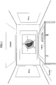
- FIG. 1 is a diagram illustrating an example of an environment using multiple displays that are arranged on the left and right walls, front and rear walls, ceiling, floor, table (table top), and the like. In such an environment with multiple displays, it is assumed that discussion and brainstorming will be performed on various themes.
- FIG. 2 is a diagram illustrating an example of a scene of brainstorming, where contents of digital sticky notes with written ideas are arranged in a personal workspace, and the contents C1 and C2 to be shared with other members are transferred (dispatched) by the respective users to a shared space. This makes it easier for an administrative user to handle the contents in the shared space.
- a user When transferring a content, a user drags (slides) the content with a finger or a pen and releases it; as a result, the content starts being transferred at an initial speed according to a speed of being dragged in a dragged direction, and stops after being transferred by a predetermined distance with deceleration including a virtual dynamic friction coefficient.
- Patent Documents 1 and 2 disclose a control technique for using a large number of displays; however, the disclosed technology merely involves a display for browsing, and does not consider an operation on the displayed contents.
- the transferred content does not stop promptly, which will result not obtaining an operation result as desired.
- the arrangement in the loop refers to a mode in which a display area of one display is connected via a display area of another display to the display area of the initial one display.
- a predetermined dynamic friction coefficient is virtually set for transferring the contents; however, when a user drags the content vigorously and releases the content, the transferred content does not stop at a desired destination and may still continue moving after having returned to the original position.
- a content control apparatus includes multiple display units having respective display areas arranged in a loop, a memory storing a set of instructions of a content control program; and one or more processors programmed to execute the set of instructions to perform a process.
- the process includes displaying a content on any one of the plurality of display units, transferring the content, in response to a sliding operation on the content displayed on a corresponding one of the display units, from the display unit acting as a starting point that initially displays the content, to pass sequentially through other display units, and stopping the content in response to the transferred content being transferred to a predetermined position.
- a direction of a content being displayed on a display (screen) is straightforward in the case of all displays (screens) being oriented in the same direction.
- the displays are in various locations in a room as illustrated in FIG. 1 , it is necessary to determine a display direction of a content in order to transfer the content between the displays. That is, a display method that is reasonable and easy to understand is required by controlling the connection method of the displays and the directions of the displayed content.
- connection of the displays and the direction of the displayed content may be controlled by determining upward and downward directions and leftward and rightward directions on each display in advance so as to display the content in the corresponding determined direction when transferring the content between the displays.
- the direction of the displayed content changes every time the content is transferred between displays; hence, a user and viewers need to be conscious of the direction with respect to each display.
- a table in a case of a table, a table is not used from one direction only and may be used in all directions; from the top, bottom, left, and right. Accordingly, it will be complicated to control determining the directions in advance, specifically, in a case of a large number of displays.
- a model (sphere geometry) is introduced; this model includes projecting a display from the center of a circumscribed sphere to a spherical surface of the circumscribed sphere of a certain space (room), developing the projected display as a plane, and capturing connection relationships between the displays. That is, it is assumed that all displays are in contact with some adjacent display, and transferring a content between the displays is controlled based on the connection relationships.
- FIG. 3A when displays are arranged on left and right walls, front and rear walls, the ceiling, and a table of the room, respectively, and the displays are developed as a plane, the displays are arranged as illustrated in FIG. 3B .
- FIG. 3C illustrates connection relationships between the front wall, the left wall, the right wall, the ceiling, the table, and the rear wall with supplementary lines with arrows.
- FIG. 4 illustrates the connection relationship between respective displays stereoscopically.
- FIG. 5 is a diagram illustrating a configuration example of a system according to an embodiment, which is an example of an environment provided with six displays (display units) of front wall, left wall, right wall, ceiling, table, and rear wall as illustrated in FIG. 4 .
- the system includes display control apparatuses 3 (3F, 3L, 3R, 3C, 3T, 3B) configured to control respective display units 4 (4F, 4L, 4R, 4C, 4T, 4B) and that are connected to a server apparatus 1 via a wired or wireless network 2.
- Examples of the display unit 4 include a projector, and a flat panel such as an LCD (Liquid Crystal Display).
- a touch panel or the like is provided on the surface of the display unit 4 such that coordinate information of an operation by a user's finger or pen may be acquired.
- one display control apparatus 3 is provided for each display unit 4; however, a smaller number of display control apparatuses 3 than of the display units 4 may control the display units 4.
- any of the display control apparatuses 3 may have the function of the server apparatus 1.
- FIG. 6 is a diagram illustrating a functional configuration example of the server apparatus 1.
- the server apparatus 1 includes a content creating instruction receiver 11, a content creating unit 12, and a content position reporting unit 13.
- the server apparatus 1 includes a content transfer instruction receiver 14, a content transfer processor 15, a display connection relationship determination unit 16, a content transfer speed determination unit 17, and a loop determination unit 18.
- the server apparatus 1 includes a display management table T1 and a content management table T2 for referring/updating at the time of processing.
- the content creating instruction receiver 11 has a function of receiving a content creating instruction from any one of the display control apparatuses 3.
- the content creating instruction is, for example, an instruction to create a digital sticky note, and includes an identifier of the display unit 4 on which handwriting input or the like has been performed, input coordinates (coordinates of a representative position where input is made), input contents (character string) and the like.
- the content creating unit 12 has a function of creating content based on the content creating instruction received by the content creating instruction receiver 11. Information of the created content is stored in the content management table T2.
- the content position reporting unit 13 has a function of reporting the identifier and display position of the content created by the content creation unit 12 to the display control apparatus 3 corresponding to the display unit 4 that displays the content.
- the content position reporting unit 13 also has a function of reporting a content and a display position to be transferred by the content transfer processor 15 to the display control apparatus 3 corresponding to the display unit 4 that displays the content.
- the content transfer instruction receiver 14 has a function of receiving a content transfer instruction from any one of the display control apparatuses 3.
- the content transfer instruction is provided with the identifier of the content to be transferred, the transfer direction, the speed of the transferring operation, and the like.
- the content transfer processor 15 has a function of transferring the content based on the content transfer instruction received by the content transfer instruction receiver 14. Information of the transferred content is stored in the content management table T2.
- the display connection relationship determination unit 16 has a function of determining whether the content is transferred from one display unit 4 to another display unit 4 in the processing in the content transfer processor 15.
- the display connection relationship determination unit 16 refers to the display management table T1 and the content management table T2 at the time of processing.
- the content transfer speed determination unit 17 has a function of determining the transfer speed of the content at the time of processing with respect to the content transfer processor 15.
- the content transfer speed determination unit 17 refers to the content management table T2 at the time of processing. It is assumed that the transfer speed imitates an object that slides while decelerating with a predetermined dynamic friction coefficient on the ground plane. That is, the transfer speed starts from the initial speed corresponding to the speed of the operation, and gradually decelerates with respect to the direction in which the operation for transferring the content was performed.
- the loop determination unit 18 has a function of determining whether to stop the transferred content in order to prevent the content from continuing circling around due to the loop of the display areas according to whether the transferred content has attained a position to stop, with respect to the processing of the content transfer processor 15.
- the loop determination unit 18 refers to the display management table T1 and the content management table T2 at the time of processing. As will be described later, when maximizing the dynamic friction coefficient at the boundary or the like such that the content stops spontaneously at the boundary or the like, a function of the loop determination unit 18 is performed by the content transfer processor 15.
- the display control apparatus 3 includes an input processor 31, a content creating instruction reporting unit 32, a content transfer instruction reporting unit 33, a content position receiver 34, a content position controller 35, and a browser 36.
- the input processor 31 has a function of receiving an operation input by a user.
- the present embodiment involves an operation for creating a content and an operation for transferring the content; however, the operation input is not specifically limited to these examples.
- the operation for creating the content is performed by handwriting input to a desired position on the display unit 4, for the digital sticky note.
- the operation for transferring the content is performed by dragging (sliding operation) the content displayed on the display unit 4.
- the content creating instruction reporting unit 32 has a function of reporting a content creating instruction to the server apparatus 1 when the input processor 31 receives an operation for creating the content.
- the information included in the content creating instruction is as described above.
- the content transfer instruction reporting unit 33 has a function of transferring a content transfer instruction to the server apparatus 1 when the input processor 31 receives an operation for transferring the content.
- the information included in the content transfer instruction is as described above.
- the content position receiver 34 has a function of receiving a content position reporting instruction from the server apparatus 1.
- the content position report includes an identifier of the content and a display position. The detail of the content may be obtained based on an identifier of the content.
- the content position controller 35 has a function of controlling a display position of the content based on the identifier and the display position of the content received by the content position receiver 34.
- the browser 36 has a function of displaying the content corresponding to the display position instructed by the content position controller 35.
- FIG. 7 is a diagram illustrating examples of data structures of various tables.
- the display management table T1 includes items such as "display ID”, “(surface direction)”, “(absolute coordinates)", “(screen physical size)”, “screen resolution”, “left side connection information”, “right side connection information”, “upper side connection information”, and “lower connection information”.
- the display management table T1 has information of "(circumscribed sphere absolute coordinate)” and "(circumscribed sphere radius)" separately from the information for each display.
- the “display ID” is information (identifier) for identifying a display unit 4.
- the “(surface direction)” represents, for example, three-dimensional rotation to the target display unit 4 with the Euler angle, roll, pitch, yaw etc. on the basis of the front display unit 4 (on the front wall).
- the "(absolute coordinates)” is the absolute coordinates of the base point of the display unit 4 (e.g., the lower left corner of the screen acting as the origin of the local coordinates).
- the “(screen physical size)” is a physical length in vertical and horizontal directions of the screen of the display unit 4.
- the “screen resolution” is the number of vertical and horizontal pixels on the screen of the display unit 4.
- the “left side connection information” is connection information on the screen of another display unit 4 connected to the left side of the display unit 4, including a display ID and a connection range (a range within which the side may be connected, the position of the connected counterpart etc.).
- the "right connection information”, “upper connection information” and “lower connection information” are connection information on the right side, the upper side, and the lower side of the display unit 4, respectively.
- the "(circumscribed sphere absolute coordinates)" is absolute coordinates of the center of a sphere (circumscribed sphere) circumscribing the space (room) where the display unit 4 is arranged.
- the "(circumscribed sphere radius)” is a radius of the circumscribed sphere.
- the content management table T2 has items such as “content ID”, “type”, “detail”, “display ID”, “local coordinates”, and "(absolute coordinates)". Hence, the "(absolute coordinates)" may be unnecessary in a case of performing processing on local coordinates in the first process example and the second process example described later.
- the “content ID” is information (identifier) for identifying a content.
- T “type” is information indicating a type of content (e.g., a digital sticky note).
- the “detail” is a detail of content (a character string to be entered in the case of digital sticky notes).
- the “display ID” is a display ID of the display unit 4 on which the content is currently displayed.
- the "local coordinates” is local coordinates of the base point of the content.
- the “(absolute coordinates)” is absolute coordinates of the base point of the content.
- FIG. 8 is a diagram illustrating a hardware configuration example of the server apparatus 1 and the display control apparatus 3, each of which has a configuration of a general information processing apparatus (computer).
- the server apparatus 1 and the like include a CPU (Central Processing Unit) 101, a ROM (Read Only Memory) 102, a RAM (Random Access Memory) 103, and a HDD (Hard Disk Drive)/SSD (Solid State Drive) 104.
- the server apparatus 1 and the like include a connection I/F (interface) 105 and a communication I/F 106.
- the CPU 101 comprehensively controls operations of the server apparatus 1 and the like by executing programs stored in the ROM 102 or the HDD/SSD 104 or the like, using the RAM 103 as a work area.
- the connection I/F 105 is an interface with a device or an apparatus connected to the server apparatus 1 and the like.
- the communication I/F 106 is an interface for communicating with another information processing apparatus via a network.
- the functions of the server apparatus 1 and the like described with reference to FIG. 6 are implemented by executing a predetermined program with respect to the CPU 101.
- the program may be acquired via a recording medium, may be acquired via a network, or may be embedded in a ROM.
- FIG. 9 is a sequence diagram illustrating a process example according to the embodiment.
- a user when a user intends to create a content such as a digital sticky note, the user performs a content creating operation on, for example, a display unit 4R (not illustrated) near the user, and this user's operation is performed by an input processor 31 of a corresponding display control apparatus 3R (step S101).
- the content creating instruction reporting unit 32 of the display control apparatus 3R reports a content creating instruction accompanied by the content type, content (character string, etc.), input position, and the like to the server apparatus 1 (step S102).
- the content creating unit 12 creates a content according to the content creating operation and registers information of the created content in the content management table T2 (step S103). For example, in a case of creating a digital sticky note, a new content ID is issued, the input character string is used as a content, local coordinates starting from the input position are set as a display position, and the ID of the display unit 4R is set as a display ID. Then, the content position reporting unit 13 reports the content ID and display position of the created content to the display control apparatus 3R corresponding to the display unit 4R to which the input operation has been performed (step S104).
- the content position controller 35 instructs the browser 36 to display the content, and the browser 36 displays the content on the corresponding display unit 4R (step S105).
- the browser 36 acquires content display data based on the content ID from the server apparatus 1.
- the user When the user intends to transfer the display position of the content, the user performs a content transfer operation on the display unit 4R on which the content is displayed, and this operation is input by the input processor 31 of the corresponding display control apparatus 3R (step S106). For example, when the user intends to "throw" the content to a distant position, the user momentarily drags the content with the user's hand in a direction in which the content is desired to be thrown, and releases the user's hand.
- the content transfer instruction reporting unit 33 of the display control apparatus 3R reports the content transfer instruction accompanied by the content ID, the transfer direction, the dragging speed, and the like to the server apparatus 1 (step S107).
- the content transfer processor 15 When the content transfer instruction is received by the content transfer instruction receiver 14 of the server apparatus 1, the content transfer processor 15 performs a content transfer process (step S108). This transfer process is performed by the content transfer speed determination unit 17, the display connection relationship determination unit 16, and the loop determination unit 18. That is, the content transfer speed determination unit 17 determines a transfer speed of the content in consideration of an initial speed of the content and a dynamic friction coefficient. The display connection relationship determination unit 16 determines whether the content is transferred across the displays. The loop determination unit 18 determines whether to stop the content according to whether the content has attained a predetermined position. Details of the process will be described later.
- the content transfer processor 15 reports the content ID and the display position of a transfer destination to the display control apparatus 3R via the content position reporting unit 13, with a predetermined time as a unit (step S109).
- the content position controller 35 instructs the browser 36 to display the content.
- the browser 36 displays the content (accompanied by erasing the original display) on the corresponding display unit 4R (step S110).
- reporting of the content ID and the display position of the transfer destination from the server apparatus 1 is repeated with a predetermined time as a unit, and the display control apparatus 3R performs display control.
- the display control apparatus 3R performs display control.
- a fixed boundary (boundary line) is set in either a vertical direction or a horizontal direction on any of the displays 4 in order to stop the content that has been transferred to the boundary.
- the content stopped at the boundary is released and becomes transferrable once the stop from the boundary is released, and after passing through the boundary, the released content is again stopped at the next pass.
- FIG. 10 is a diagram illustrating an operation example in the first process example, in which the display unit 4 is arranged on the front wall, the left wall, the right wall, the ceiling, the table, and the rear wall, similar to the case illustrated in FIG. 4 . Further, in this example, a vertical boundary is provided in a part of the left wall as indicated by a broken line. In this state, for example, when an operation for vigorously transferring the content displayed on the right wall to the right direction is performed, the content enters the left wall via the rear wall as indicated by a thick line. Thereafter, when the content attains the boundary, the content is stopped as indicated by "x". As a result, even when the transfer operation is too strong without adjustment, it is possible to prevent the content from continuing circling around.
- FIG. 11 illustrates a similar operation as in FIG. 10 in a state where the displays are developed as a plane similar to FIG. 3C .
- FIG. 12 illustrates an example of data managed by the first process example, which has data for setting boundary coordinates and a stop flag for each content.
- a y coordinate value of the local coordinates indicates the boundary coordinates for setting the boundary in the vertical direction
- an x coordinate value of the local coordinates indicates the boundary coordinates for setting the boundary in the horizontal direction.
- the stop flag signifies stopping without allowing passing through the boundary when ON, and permits passing through the boundary when OFF.
- FIG. 13 is a diagram illustrating a flowchart in the first process example, which indicates a process corresponding to the content transfer process (step S108) in FIG. 9 .
- the content transfer processor 15 obtains the display position of the content after a unit time on the display based on the transfer direction and the transfer speed determined by the content transfer speed determination unit 17, and transfers the content (step S11).
- the content transfer processor 15 determines whether the content is about to pass through the boundary (step S12).
- the content transfer processor 15 determines that the content is not about to pass through the boundary (No in step S12), the content transfer processor 15 returns to the transfer of the content (step S11).
- step S12 the content transfer processor 15 determines whether the stop flag of the content is ON (step S13). Note that it is assumed that the stop flag is set to ON at the time of content creation.
- step S13 When the content transfer processor 15 determines that the stop flag of the content is ON (Yes in step S13), the content transfer processor 15 stops the transfer of the content (step S14) and sets the stop flag of the content to OFF (step S15).
- step S13 When the content transfer processor 15 determines that the stop flag of the content is OFF (No in step S13), the content transfer processor 15 passes the content through the boundary (step S16), sets the stop flag of the content to ON (step S17), and continues the transferring process.
- the boundary is not fixed; the boundary is instead dynamically set at the transfer start position for each content in order to stop the content that has again attained the boundary.
- FIG. 14 is a diagram illustrating an operation example in the second process example, in which the display 10 is arranged on the front wall, the left wall, the right wall, the ceiling, the table, and the rear wall, similar to the case illustrated in FIG. 10 .
- a boundary indicated by a broken line is initially set at the transfer start position.
- the content is transferred and enters the right wall again sequentially via the rear wall, the left wall and the front wall as indicated by a thick line. Thereafter, when the content attains the boundary corresponding to the transfer start position, the content is stopped as indicated by "x".
- FIG. 15 illustrates a similar operation as in FIG. 14 in a state where the displays are developed as a plane similar to FIG. 11 .
- FIG. 16 illustrates an example of data managed by the second process example, and boundary coordinates corresponding to the transfer start position are held for each content.
- FIG. 17 is a diagram illustrating a flowchart in the second process example, which indicates a process corresponding to the content transfer process (step S108) in FIG. 9 .
- the content transfer processor 15 when starting the process, records the content ID and the transfer start position in association with each other to create a provisional boundary (step S21).
- the content transfer processor 15 obtains the display position of the content after a unit time on the display based on the transfer direction and the transfer speed determined by the content transfer speed determination unit 17, and transfers the content (step S22).
- the content transfer processor 15 determines whether the content is about to pass through the boundary (step S23).
- the content transfer processor 15 determines that the content is not about to pass through the boundary (No in step S23), the content transfer processor 15 returns to the transfer of the content (step S22).
- the content transfer processor 15 determines whether the content ID of the content that is about to pass through the boundary matches the content ID associated with the boundary coordinates (step S24).
- the content transfer processor 15 determines that the two content IDs match (Yes in step S24), the content transfer processor 15 stops the transfer of the content (step S25), and then erases the recorded corresponding position and deletes the provisional boundary (Step S26).
- the content transfer processor 15 determines that the two content IDs do not match (No in step S24)
- the content transfer processor 15 passes the content through the boundary (step S27) and continues the transferring process.
- a straight line from the center of the circumscribed sphere of the space (room) in which the display unit 4 is arranged to the content is used to determine whether the content has attained the transfer start position of a corresponding one of the contents.
- FIG. 18 is a diagram illustrating an operation example in the third process example, in which a left diagram indicates the arrangement of the displays in the room and the circumscribed sphere, and a right diagram indicates the outlines of the respective displays being projected on spherical surfaces of the circumscribed sphere.
- a left diagram indicates the arrangement of the displays in the room and the circumscribed sphere
- a right diagram indicates the outlines of the respective displays being projected on spherical surfaces of the circumscribed sphere.
- the angle formed between the straight line from the center of the circumscribed sphere to the transfer start position for each content and the straight line from the center of the circumscribed sphere to the position of the transferred content may be regarded to be of zero value and the transfer is stopped.
- FIG. 19 is a diagram illustrating a flowchart in the third process example, which indicates a process corresponding to the content transfer process (step S108) in FIG. 9 .
- the content transfer processor 15 calculates a transfer distance between the transfer start point and a point at which a unit time has elapsed from the transfer start point (step S31). This calculation is performed as illustrated in FIG. 20B on the basis of assumption illustrated in FIG. 20A .
- the content transfer processor 15 subsequently displays the content at a position in the transfer direction designated as the transfer distance (step S32).
- the content transfer processor 15 subsequently calculates a transfer angle from the position of the content and the transfer start point, or calculates the transfer angle per unit time (step S33). This calculation is performed as illustrated in FIG. 20C .
- the transfer angle per unit time is calculated in order to handle a case where the resolution and the connection range of the display are different between displays, as illustrated in FIG. 21 . That is, in FIG. 21 , the right side of the right wall is connected along the entire range of the left side of the rear wall such that magnification or compression may be performed, however, the left side of the right wall is connected only to the upper half of the right side of the front wall. Therefore, when the content C1 at the lower position P1 on the rear wall is assumed to horizontally be moved to the left, the content C1 will also be moved to a lower position P2 on the right wall; however, when the content C1 is further moved to the front wall, the content C1 will be moved to an upper position P3 on the front wall.
- the position will be misaligned only with respect to the transfer angle between the transfer start time and the current position of the content.
- the content transfer processor 15 determines whether the transfer angle has attained 0 (a value that may be regarded as 0 in consideration of an error) or whether a total of the transfer angles per unit time has attained 2n radians (a value that may be regarded as 2n radians in consideration of an error) corresponding to a circumference (a turn) (step S34).
- the content transfer processor 15 determines that the transfer angle has not attained 0 or the total of the transfer angles per unit time has not attained 2n radians (No in step S34), the content transfer processor 15 calculates the transfer distance at a time at which the unit time has elapsed from that position (calculates the transfer distance by updating the transfer direction vector when transferred between walls) (in step S35). This calculation is performed as illustrated in FIGS. 20D and 20E .
- step S34 when the content transfer processor 15 determines that the transfer angle is 0 or the total of the transfer angles has attained 2n (Yes in step S34), the content transfer processor 15 stops transferring the content (step S36).
- the transferred content instead of stopping the transferred content abruptly at the boundary or at the transfer start position in the process example described above, the transferred content will be stopped naturally by setting of the dynamic friction coefficient such that the local maximum value of the dynamic friction coefficient will be at the boundary or at the transfer start position.
- the dynamic friction coefficient is reduced immediately after the start of the transfer.
- FIGS. 22A and 22B are diagrams illustrating an example of setting of a dynamic friction coefficient in the vicinity of a boundary in the fourth process example.
- the dynamic friction coefficient is linearly increased in the vicinity of the boundary or the like.
- the dynamic friction coefficient may be set by a linear equation based on positional coordinates of the content.
- the dynamic friction coefficient increases in a curve in the vicinity of the boundary or the like.
- the dynamic friction coefficient may be set by a formula such as a normal distribution with respect to positional coordinates of the content.
- FIG. 23 is a diagram illustrating examples of a normal distribution, indicating that various characteristics may be obtained by changing the mean or dispersion value.
- FIG. 24 is a diagram illustrating a flowchart in the fourth process example, which indicates a process corresponding to the content transfer process (step S108) in FIG. 9 .
- the content transfer processor 15 sets a current point as a transfer start point (step S401).
- the content transfer processor 15 calculates the transfer distance at a time at which a unit time has elapsed, based on the current dynamic friction coefficient (step S402).
- the calculation is performed as illustrated in FIG. 25B with respect to the characteristic of FIG. 22A
- the calculation is performed as illustrated in FIG. 25C with respect to the characteristic of FIG. 22B .
- l 0 is the first transfer distance of the first unit time after the start of transfer
- l 1 is the second transfer distance of the second unit time subsequent to the first unit time
- l n is the (n-1)th transfer distance of the (n-1)th unit time.
- the content transfer processor 15 determines whether the dynamic friction coefficient is greater than a predetermined value (step S403).
- the content transfer processor 15 determines whether the transfer distance is 0 (step S406). When the content transfer processor 15 determines that the transfer distance is not 0 (No in step S406), the content transfer processor 15 determines the current point as a transfer destination (step S407) and returns to the calculation of the transfer distance (step S402). When the content transfer processor 15 determines that the transfer distance is 0 (Yes in step S406), the content transfer processor 15 ends the process.
- the content transfer processor 15 determines that the dynamic friction coefficient is not greater than the predetermined value (No in step S403), the content transfer processor 15 displays the content at the transfer distance position (step S409), and determines whether the transfer distance is 0 (step S410).
- step S410 the content transfer processor 15 calculates the transfer distance at a time at which the unit time has elapsed with the current dynamic friction coefficient (step S408), using the current time as the transfer destination (step S411), and shifts to the display of the content (step S409).
- step S408 the content transfer processor 15 determines that the transfer distance is 0 (Yes in step S410)
- the content transfer processor 15 ends the process.
- Local coordinates are coordinates of a two-dimensional plane of the display area of each display unit 4. For example, a lower left corner of each display unit 4 is the origin, a vertical axis is an x axis, and a horizontal axis is a y axis. Absolute coordinates are physical three-dimensional coordinates.
- Displaying (drawing) content and transferring determination of content between displays in each of the process examples described above may preferably be performed with local coordinates, and calculating the transfer angle in the third process example may preferably be performed with absolute coordinates.
- the transfer of contents is more easily to be determined with local coordinates.
- the transfer angle is more easily to be calculated with absolute coordinates.
- the arrangement of the display of FIG. 10 will be described with an example. It is assumed that the origin of the local coordinates of the display on the right wall is the lower left corner, the size of the display area in the vertical direction (x axis direction) is a r , and the size of the display area in the right direction (y axis direction) is b r .
- the plane direction and the absolute coordinates of the base point and the screen physical size are managed for each display, which enables the local coordinates to be converted into absolute coordinates.
- Such a management in the display management table T1 also enables conversion of the transfer direction vector on the display in one plane direction to the transfer direction vector on the display in the other plane direction.
- the transfer direction vector A (x a , y a , z a ) on the right wall becomes a transfer direction vector A' as the content is transferred to the rear wall.
- A' BA based on a rotation matrix B obtained from ⁇ , ⁇ and ⁇ .
- Rotation with respect to each display surface may be determined in advance by setting a reference surface (e.g., the front wall) and the rotation from the reference surface by the Euler angles or the like.
- a reference surface e.g., the front wall
- five rotations with respect to front wall, right wall, left wall, rear wall, ceiling and table are determined in advance. Accordingly, it is only necessary for the content to pass through the front wall once for the rotation between desired surfaces. For example, to rotate the content to the table from the right wall, it is sufficient to perform rotation from the right to the front and rotation from the front to the table.
- R represents the rotation matrix from the front wall to the right wall
- L represents the rotation matrix from the front wall to the left wall
- B represents the rotation matrix from the front wall to the rear wall
- C represents the rotation matrix of the ceiling
- T represents the rotation matrix of the table.
- it is possible to define transfers between all the adjacent walls (12 ways ⁇ 2 24 ways, including the transferring of the content in the opposite directions).
- the display unit 4 is an example of a "display unit”.
- the display control apparatus 3 is an example of a "display controller”.
- the content transfer processor 15 is an example of a "content controller”.
- the loop determination unit 18 is an example of a "stop unit”.
Landscapes
- Engineering & Computer Science (AREA)
- Theoretical Computer Science (AREA)
- Physics & Mathematics (AREA)
- General Physics & Mathematics (AREA)
- General Engineering & Computer Science (AREA)
- Human Computer Interaction (AREA)
- Multimedia (AREA)
- Computer Hardware Design (AREA)
- Computer Graphics (AREA)
- User Interface Of Digital Computer (AREA)
- Information Transfer Between Computers (AREA)
Abstract
Description
- The embodiments discussed herein relate to a content control apparatus, a content control program, and a content control method.
- Multiple displays may be connected in response to a request for displaying a large number of contents on a large screen. For example, one wall of a room may be covered with multiple displays appearing as a single display; this may achieve a large screen.
-
FIG. 1 is a diagram illustrating an example of an environment using multiple displays that are arranged on the left and right walls, front and rear walls, ceiling, floor, table (table top), and the like. In such an environment with multiple displays, it is assumed that discussion and brainstorming will be performed on various themes. -
FIG. 2 is a diagram illustrating an example of a scene of brainstorming, where contents of digital sticky notes with written ideas are arranged in a personal workspace, and the contents C1 and C2 to be shared with other members are transferred (dispatched) by the respective users to a shared space. This makes it easier for an administrative user to handle the contents in the shared space. - When transferring a content, a user drags (slides) the content with a finger or a pen and releases it; as a result, the content starts being transferred at an initial speed according to a speed of being dragged in a dragged direction, and stops after being transferred by a predetermined distance with deceleration including a virtual dynamic friction coefficient.
- The related art technology (e.g.,
Patent Documents 1 and 2) discloses a control technique for using a large number of displays; however, the disclosed technology merely involves a display for browsing, and does not consider an operation on the displayed contents. -
- Patent Document 1: Japanese Laid-open Patent Publication No.
2012-124759 - Patent Document 2: Japanese Laid-open Patent Publication No.
2006-189637 - As described above, when an operation to transfer the contents is performed in an environment in which multiple displays are connected, and display areas of the displays are arranged in a loop, the transferred content does not stop promptly, which will result not obtaining an operation result as desired. Note that the arrangement in the loop refers to a mode in which a display area of one display is connected via a display area of another display to the display area of the initial one display.
- That is, a predetermined dynamic friction coefficient is virtually set for transferring the contents; however, when a user drags the content vigorously and releases the content, the transferred content does not stop at a desired destination and may still continue moving after having returned to the original position.
- According to an embodiment, a content control apparatus includes multiple display units having respective display areas arranged in a loop, a memory storing a set of instructions of a content control program; and one or more processors programmed to execute the set of instructions to perform a process. The process includes displaying a content on any one of the plurality of display units, transferring the content, in response to a sliding operation on the content displayed on a corresponding one of the display units, from the display unit acting as a starting point that initially displays the content, to pass sequentially through other display units, and stopping the content in response to the transferred content being transferred to a predetermined position.
- According to embodiments, it is possible to stop a content that has undergone a transfer operation from continuing to be transferred even in a case where the display areas are arranged in a loop.
-
-
FIG. 1 is a diagram illustrating an example of an environment in which multiple displays are used; -
FIG. 2 is a diagram illustrating an example of a scene of brainstorming; -
FIGS. 3A to 3C are diagrams (part 1) illustrating an example of connection of displays; -
FIG. 4 is a diagram (part 2) illustrating an example of connection of displays; -
FIG. 5 is a diagram illustrating a configuration example of a system according to an embodiment; -
FIG. 6 is a diagram illustrating functional configuration examples of a server apparatus and a display control apparatus; -
FIG. 7 is a diagram illustrating examples of data structures of various tables; -
FIG. 8 is a diagram illustrating hardware configuration examples of a server apparatus and a display control apparatus; -
FIG. 9 is a sequence diagram illustrating an overall process example according to an embodiment; -
FIG. 10 is a diagram (part 1) illustrating an operation example in a first process example; -
FIG. 11 is a diagram (part 2) illustrating the operation example in the first process example; -
FIG. 12 is an example of data managed in the first process example; -
FIG. 13 is a diagram illustrating a flowchart in the first process example; -
FIG. 14 is a diagram (part 1) illustrating an operation example in a second process example; -
FIG. 15 is a diagram (part 2) illustrating the operation example in the second process example; -
FIG. 16 is an example of data managed in the second process example; -
FIG. 17 is a diagram illustrating a flowchart in the second process example; -
FIG. 18 is a diagram illustrating an operation example in a third process example; -
FIG. 19 is a diagram illustrating a flowchart in the third process example; -
FIGS. 20A to 20E are diagrams illustrating calculation formulas in the third process example; -
FIG. 21 is a diagram illustrating an example of a case where determination is made by a total of transfer angles per unit time; -
FIGS. 22A and 22B are diagrams illustrating an example of setting of a dynamic friction coefficient in the vicinity of a boundary in a fourth process example; -
FIG. 23 is a diagram illustrating examples of normal distributions; -
FIG. 24 is a diagram illustrating a flowchart in the fourth process example; and -
FIGS. 25A to 25C are diagrams illustrating calculating formulas in the fourth process example. - The following illustrates various embodiments with reference the accompanying drawings.
- A direction of a content being displayed on a display (screen) is straightforward in the case of all displays (screens) being oriented in the same direction. However, when the displays are in various locations in a room as illustrated in
FIG. 1 , it is necessary to determine a display direction of a content in order to transfer the content between the displays. That is, a display method that is reasonable and easy to understand is required by controlling the connection method of the displays and the directions of the displayed content. - The connection of the displays and the direction of the displayed content may be controlled by determining upward and downward directions and leftward and rightward directions on each display in advance so as to display the content in the corresponding determined direction when transferring the content between the displays. However, the direction of the displayed content changes every time the content is transferred between displays; hence, a user and viewers need to be conscious of the direction with respect to each display.
- In addition, in a case of a table, a table is not used from one direction only and may be used in all directions; from the top, bottom, left, and right. Accordingly, it will be complicated to control determining the directions in advance, specifically, in a case of a large number of displays.
- In order to handle such complications, a model (sphere geometry) is introduced; this model includes projecting a display from the center of a circumscribed sphere to a spherical surface of the circumscribed sphere of a certain space (room), developing the projected display as a plane, and capturing connection relationships between the displays. That is, it is assumed that all displays are in contact with some adjacent display, and transferring a content between the displays is controlled based on the connection relationships.
- As illustrated in
FIG. 3A , when displays are arranged on left and right walls, front and rear walls, the ceiling, and a table of the room, respectively, and the displays are developed as a plane, the displays are arranged as illustrated inFIG. 3B . Further,FIG. 3C illustrates connection relationships between the front wall, the left wall, the right wall, the ceiling, the table, and the rear wall with supplementary lines with arrows. In addition,FIG. 4 illustrates the connection relationship between respective displays stereoscopically. -
FIG. 5 is a diagram illustrating a configuration example of a system according to an embodiment, which is an example of an environment provided with six displays (display units) of front wall, left wall, right wall, ceiling, table, and rear wall as illustrated inFIG. 4 . InFIG. 5 , the system includes display control apparatuses 3 (3F, 3L, 3R, 3C, 3T, 3B) configured to control respective display units 4 (4F, 4L, 4R, 4C, 4T, 4B) and that are connected to aserver apparatus 1 via a wired orwireless network 2. Examples of the display unit 4 include a projector, and a flat panel such as an LCD (Liquid Crystal Display). Further, a touch panel or the like is provided on the surface of the display unit 4 such that coordinate information of an operation by a user's finger or pen may be acquired. Note that onedisplay control apparatus 3 is provided for each display unit 4; however, a smaller number ofdisplay control apparatuses 3 than of the display units 4 may control the display units 4. In addition, any of thedisplay control apparatuses 3 may have the function of theserver apparatus 1. -
FIG. 6 is a diagram illustrating a functional configuration example of theserver apparatus 1. InFIG. 6 , theserver apparatus 1 includes a content creatinginstruction receiver 11, acontent creating unit 12, and a contentposition reporting unit 13. In addition, theserver apparatus 1 includes a contenttransfer instruction receiver 14, acontent transfer processor 15, a display connectionrelationship determination unit 16, a content transferspeed determination unit 17, and aloop determination unit 18. Theserver apparatus 1 includes a display management table T1 and a content management table T2 for referring/updating at the time of processing. - The content creating
instruction receiver 11 has a function of receiving a content creating instruction from any one of thedisplay control apparatuses 3. The content creating instruction is, for example, an instruction to create a digital sticky note, and includes an identifier of the display unit 4 on which handwriting input or the like has been performed, input coordinates (coordinates of a representative position where input is made), input contents (character string) and the like. - The
content creating unit 12 has a function of creating content based on the content creating instruction received by the content creatinginstruction receiver 11. Information of the created content is stored in the content management table T2. - The content
position reporting unit 13 has a function of reporting the identifier and display position of the content created by thecontent creation unit 12 to thedisplay control apparatus 3 corresponding to the display unit 4 that displays the content. The contentposition reporting unit 13 also has a function of reporting a content and a display position to be transferred by thecontent transfer processor 15 to thedisplay control apparatus 3 corresponding to the display unit 4 that displays the content. - The content
transfer instruction receiver 14 has a function of receiving a content transfer instruction from any one of thedisplay control apparatuses 3. The content transfer instruction is provided with the identifier of the content to be transferred, the transfer direction, the speed of the transferring operation, and the like. - The
content transfer processor 15 has a function of transferring the content based on the content transfer instruction received by the contenttransfer instruction receiver 14. Information of the transferred content is stored in the content management table T2. - The display connection
relationship determination unit 16 has a function of determining whether the content is transferred from one display unit 4 to another display unit 4 in the processing in thecontent transfer processor 15. The display connectionrelationship determination unit 16 refers to the display management table T1 and the content management table T2 at the time of processing. - The content transfer
speed determination unit 17 has a function of determining the transfer speed of the content at the time of processing with respect to thecontent transfer processor 15. The content transferspeed determination unit 17 refers to the content management table T2 at the time of processing. It is assumed that the transfer speed imitates an object that slides while decelerating with a predetermined dynamic friction coefficient on the ground plane. That is, the transfer speed starts from the initial speed corresponding to the speed of the operation, and gradually decelerates with respect to the direction in which the operation for transferring the content was performed. - The
loop determination unit 18 has a function of determining whether to stop the transferred content in order to prevent the content from continuing circling around due to the loop of the display areas according to whether the transferred content has attained a position to stop, with respect to the processing of thecontent transfer processor 15. Theloop determination unit 18 refers to the display management table T1 and the content management table T2 at the time of processing. As will be described later, when maximizing the dynamic friction coefficient at the boundary or the like such that the content stops spontaneously at the boundary or the like, a function of theloop determination unit 18 is performed by thecontent transfer processor 15. - The
display control apparatus 3 includes aninput processor 31, a content creatinginstruction reporting unit 32, a content transferinstruction reporting unit 33, acontent position receiver 34, acontent position controller 35, and abrowser 36. - The
input processor 31 has a function of receiving an operation input by a user. The present embodiment involves an operation for creating a content and an operation for transferring the content; however, the operation input is not specifically limited to these examples. The operation for creating the content is performed by handwriting input to a desired position on the display unit 4, for the digital sticky note. The operation for transferring the content is performed by dragging (sliding operation) the content displayed on the display unit 4. - The content creating
instruction reporting unit 32 has a function of reporting a content creating instruction to theserver apparatus 1 when theinput processor 31 receives an operation for creating the content. The information included in the content creating instruction is as described above. - The content transfer
instruction reporting unit 33 has a function of transferring a content transfer instruction to theserver apparatus 1 when theinput processor 31 receives an operation for transferring the content. The information included in the content transfer instruction is as described above. - The
content position receiver 34 has a function of receiving a content position reporting instruction from theserver apparatus 1. The content position report includes an identifier of the content and a display position. The detail of the content may be obtained based on an identifier of the content. - The
content position controller 35 has a function of controlling a display position of the content based on the identifier and the display position of the content received by thecontent position receiver 34. - The
browser 36 has a function of displaying the content corresponding to the display position instructed by thecontent position controller 35. -
FIG. 7 is a diagram illustrating examples of data structures of various tables. InFIG. 7 , the display management table T1 includes items such as "display ID", "(surface direction)", "(absolute coordinates)", "(screen physical size)", "screen resolution", "left side connection information", "right side connection information", "upper side connection information", and "lower connection information". The display management table T1 has information of "(circumscribed sphere absolute coordinate)" and "(circumscribed sphere radius)" separately from the information for each display. Note that "(surface direction)", "(absolute coordinates)", "(physical screen size)", "(absolute coordinates of circumscribed sphere)", and "(circumscribed sphere radius)" are used for converting the position on the display unit 4 mutually between local coordinates (two-dimensional coordinates on the screen) and absolute coordinates (three-dimensional coordinates). Hence, the above items may be unnecessary in a case of performing processing on local coordinates in the first process example and the second process example described later. - The "display ID" is information (identifier) for identifying a display unit 4. The "(surface direction)" represents, for example, three-dimensional rotation to the target display unit 4 with the Euler angle, roll, pitch, yaw etc. on the basis of the front display unit 4 (on the front wall). The "(absolute coordinates)" is the absolute coordinates of the base point of the display unit 4 (e.g., the lower left corner of the screen acting as the origin of the local coordinates). The "(screen physical size)" is a physical length in vertical and horizontal directions of the screen of the display unit 4. The "screen resolution" is the number of vertical and horizontal pixels on the screen of the display unit 4.
- The "left side connection information" is connection information on the screen of another display unit 4 connected to the left side of the display unit 4, including a display ID and a connection range (a range within which the side may be connected, the position of the connected counterpart etc.). The "right connection information", "upper connection information" and "lower connection information" are connection information on the right side, the upper side, and the lower side of the display unit 4, respectively.
- The "(circumscribed sphere absolute coordinates)" is absolute coordinates of the center of a sphere (circumscribed sphere) circumscribing the space (room) where the display unit 4 is arranged. The "(circumscribed sphere radius)" is a radius of the circumscribed sphere.
- The content management table T2 has items such as "content ID", "type", "detail", "display ID", "local coordinates", and "(absolute coordinates)". Hence, the "(absolute coordinates)" may be unnecessary in a case of performing processing on local coordinates in the first process example and the second process example described later.
- The "content ID" is information (identifier) for identifying a content. T "type" is information indicating a type of content (e.g., a digital sticky note). The "detail" is a detail of content (a character string to be entered in the case of digital sticky notes). The "display ID" is a display ID of the display unit 4 on which the content is currently displayed. The "local coordinates" is local coordinates of the base point of the content. The "(absolute coordinates)" is absolute coordinates of the base point of the content.
-
FIG. 8 is a diagram illustrating a hardware configuration example of theserver apparatus 1 and thedisplay control apparatus 3, each of which has a configuration of a general information processing apparatus (computer). InFIG. 8 , theserver apparatus 1 and the like include a CPU (Central Processing Unit) 101, a ROM (Read Only Memory) 102, a RAM (Random Access Memory) 103, and a HDD (Hard Disk Drive)/SSD (Solid State Drive) 104. Further, theserver apparatus 1 and the like include a connection I/F (interface) 105 and a communication I/F 106. - The
CPU 101 comprehensively controls operations of theserver apparatus 1 and the like by executing programs stored in theROM 102 or the HDD/SSD 104 or the like, using theRAM 103 as a work area. The connection I/F 105 is an interface with a device or an apparatus connected to theserver apparatus 1 and the like. The communication I/F 106 is an interface for communicating with another information processing apparatus via a network. - The functions of the
server apparatus 1 and the like described with reference toFIG. 6 are implemented by executing a predetermined program with respect to theCPU 101. The program may be acquired via a recording medium, may be acquired via a network, or may be embedded in a ROM. -
FIG. 9 is a sequence diagram illustrating a process example according to the embodiment. InFIG. 9 , when a user intends to create a content such as a digital sticky note, the user performs a content creating operation on, for example, adisplay unit 4R (not illustrated) near the user, and this user's operation is performed by aninput processor 31 of a correspondingdisplay control apparatus 3R (step S101). In response to the input content creating operation, the content creatinginstruction reporting unit 32 of thedisplay control apparatus 3R reports a content creating instruction accompanied by the content type, content (character string, etc.), input position, and the like to the server apparatus 1 (step S102). - When the content creating
instruction receiver 11 of theserver apparatus 1 receives the content creating instruction, thecontent creating unit 12 creates a content according to the content creating operation and registers information of the created content in the content management table T2 (step S103). For example, in a case of creating a digital sticky note, a new content ID is issued, the input character string is used as a content, local coordinates starting from the input position are set as a display position, and the ID of thedisplay unit 4R is set as a display ID. Then, the contentposition reporting unit 13 reports the content ID and display position of the created content to thedisplay control apparatus 3R corresponding to thedisplay unit 4R to which the input operation has been performed (step S104). - When the
content position receiver 34 of thedisplay control apparatus 3R receives the report of the content ID and the display position, thecontent position controller 35 instructs thebrowser 36 to display the content, and thebrowser 36 displays the content on thecorresponding display unit 4R (step S105). When thebrowser 36 does not hold the content display data, thebrowser 36 acquires content display data based on the content ID from theserver apparatus 1. - When the user intends to transfer the display position of the content, the user performs a content transfer operation on the
display unit 4R on which the content is displayed, and this operation is input by theinput processor 31 of the correspondingdisplay control apparatus 3R (step S106). For example, when the user intends to "throw" the content to a distant position, the user momentarily drags the content with the user's hand in a direction in which the content is desired to be thrown, and releases the user's hand. In response to the input content transfer operation, the content transferinstruction reporting unit 33 of thedisplay control apparatus 3R reports the content transfer instruction accompanied by the content ID, the transfer direction, the dragging speed, and the like to the server apparatus 1 (step S107). - When the content transfer instruction is received by the content
transfer instruction receiver 14 of theserver apparatus 1, thecontent transfer processor 15 performs a content transfer process (step S108). This transfer process is performed by the content transferspeed determination unit 17, the display connectionrelationship determination unit 16, and theloop determination unit 18. That is, the content transferspeed determination unit 17 determines a transfer speed of the content in consideration of an initial speed of the content and a dynamic friction coefficient. The display connectionrelationship determination unit 16 determines whether the content is transferred across the displays. Theloop determination unit 18 determines whether to stop the content according to whether the content has attained a predetermined position. Details of the process will be described later. - Then, the
content transfer processor 15 reports the content ID and the display position of a transfer destination to thedisplay control apparatus 3R via the contentposition reporting unit 13, with a predetermined time as a unit (step S109). When thecontent position receiver 34 of thedisplay control apparatus 3R receives the report of the content ID and the display position, thecontent position controller 35 instructs thebrowser 36 to display the content. Then, thebrowser 36 displays the content (accompanied by erasing the original display) on thecorresponding display unit 4R (step S110). - Since the content continues to be transferred while decelerating by the dynamic friction coefficient, reporting of the content ID and the display position of the transfer destination from the
server apparatus 1 is repeated with a predetermined time as a unit, and thedisplay control apparatus 3R performs display control. When the content enters the display area of, for example, anadjacent display unit 4B, the content ID and the display position of the transfer destination are reported to the correspondingdisplay control apparatus 3B (step S111), and thedisplay control apparatus 3B displays the content on thedisplay unit 4B (step S112). These processes are repeated until the content transferred is stopped. - In the first process example, a fixed boundary (boundary line) is set in either a vertical direction or a horizontal direction on any of the displays 4 in order to stop the content that has been transferred to the boundary. The content stopped at the boundary is released and becomes transferrable once the stop from the boundary is released, and after passing through the boundary, the released content is again stopped at the next pass.
-
FIG. 10 is a diagram illustrating an operation example in the first process example, in which the display unit 4 is arranged on the front wall, the left wall, the right wall, the ceiling, the table, and the rear wall, similar to the case illustrated inFIG. 4 . Further, in this example, a vertical boundary is provided in a part of the left wall as indicated by a broken line. In this state, for example, when an operation for vigorously transferring the content displayed on the right wall to the right direction is performed, the content enters the left wall via the rear wall as indicated by a thick line. Thereafter, when the content attains the boundary, the content is stopped as indicated by "x". As a result, even when the transfer operation is too strong without adjustment, it is possible to prevent the content from continuing circling around.FIG. 11 illustrates a similar operation as inFIG. 10 in a state where the displays are developed as a plane similar toFIG. 3C . -
FIG. 12 illustrates an example of data managed by the first process example, which has data for setting boundary coordinates and a stop flag for each content. When an x axis of the local coordinates represents a horizontal direction and a y axis of the local coordinates represents a vertical direction, a y coordinate value of the local coordinates indicates the boundary coordinates for setting the boundary in the vertical direction, and an x coordinate value of the local coordinates indicates the boundary coordinates for setting the boundary in the horizontal direction. The stop flag signifies stopping without allowing passing through the boundary when ON, and permits passing through the boundary when OFF. -
FIG. 13 is a diagram illustrating a flowchart in the first process example, which indicates a process corresponding to the content transfer process (step S108) inFIG. 9 . InFIG. 13 , when starting the process, thecontent transfer processor 15 obtains the display position of the content after a unit time on the display based on the transfer direction and the transfer speed determined by the content transferspeed determination unit 17, and transfers the content (step S11). - Subsequently, the
content transfer processor 15 determines whether the content is about to pass through the boundary (step S12). - When the
content transfer processor 15 determines that the content is not about to pass through the boundary (No in step S12), thecontent transfer processor 15 returns to the transfer of the content (step S11). - When the
content transfer processor 15 determines that the content is about to pass through the boundary (Yes in step S12), thecontent transfer processor 15 determines whether the stop flag of the content is ON (step S13). Note that it is assumed that the stop flag is set to ON at the time of content creation. - When the
content transfer processor 15 determines that the stop flag of the content is ON (Yes in step S13), thecontent transfer processor 15 stops the transfer of the content (step S14) and sets the stop flag of the content to OFF (step S15). - When the
content transfer processor 15 determines that the stop flag of the content is OFF (No in step S13), thecontent transfer processor 15 passes the content through the boundary (step S16), sets the stop flag of the content to ON (step S17), and continues the transferring process. - In the second process example, the boundary is not fixed; the boundary is instead dynamically set at the transfer start position for each content in order to stop the content that has again attained the boundary.
-
FIG. 14 is a diagram illustrating an operation example in the second process example, in which the display 10 is arranged on the front wall, the left wall, the right wall, the ceiling, the table, and the rear wall, similar to the case illustrated inFIG. 10 . In this state, for example, when an operation for vigorously transferring the content displayed on the right wall to the right direction is performed, a boundary indicated by a broken line is initially set at the transfer start position. Then, the content is transferred and enters the right wall again sequentially via the rear wall, the left wall and the front wall as indicated by a thick line. Thereafter, when the content attains the boundary corresponding to the transfer start position, the content is stopped as indicated by "x". As a result, even when the transfer operation is too strong without adjustment, it is possible to prevent the content from continuing circling around.FIG. 15 illustrates a similar operation as inFIG. 14 in a state where the displays are developed as a plane similar toFIG. 11 . -
FIG. 16 illustrates an example of data managed by the second process example, and boundary coordinates corresponding to the transfer start position are held for each content. -
FIG. 17 is a diagram illustrating a flowchart in the second process example, which indicates a process corresponding to the content transfer process (step S108) inFIG. 9 . InFIG. 17 , when starting the process, thecontent transfer processor 15 records the content ID and the transfer start position in association with each other to create a provisional boundary (step S21). - Subsequently, the
content transfer processor 15 obtains the display position of the content after a unit time on the display based on the transfer direction and the transfer speed determined by the content transferspeed determination unit 17, and transfers the content (step S22). - Subsequently, the
content transfer processor 15 determines whether the content is about to pass through the boundary (step S23). - When the
content transfer processor 15 determines that the content is not about to pass through the boundary (No in step S23), thecontent transfer processor 15 returns to the transfer of the content (step S22). - When the
content transfer processor 15 determines that the content is about to pass through the boundary (Yes in step S23), thecontent transfer processor 15 determines whether the content ID of the content that is about to pass through the boundary matches the content ID associated with the boundary coordinates (step S24). - When the
content transfer processor 15 determines that the two content IDs match (Yes in step S24), thecontent transfer processor 15 stops the transfer of the content (step S25), and then erases the recorded corresponding position and deletes the provisional boundary (Step S26). - When the
content transfer processor 15 determines that the two content IDs do not match (No in step S24), thecontent transfer processor 15 passes the content through the boundary (step S27) and continues the transferring process. - In the third processing example, in order to handle any direction of the transfer of the content, a straight line from the center of the circumscribed sphere of the space (room) in which the display unit 4 is arranged to the content is used to determine whether the content has attained the transfer start position of a corresponding one of the contents.
-
FIG. 18 is a diagram illustrating an operation example in the third process example, in which a left diagram indicates the arrangement of the displays in the room and the circumscribed sphere, and a right diagram indicates the outlines of the respective displays being projected on spherical surfaces of the circumscribed sphere. In this state, for example, when an operation for vigorously transferring the content displayed on the right wall to a diagonally lower right direction is performed, the content enters the right wall again via the rear wall, the table, and the front wall in a sequential order as indicated by a thick line. Thereafter, when the content attains the transfer start position, the angle formed between the straight line from the center of the circumscribed sphere to the transfer start position for each content and the straight line from the center of the circumscribed sphere to the position of the transferred content may be regarded to be of zero value and the transfer is stopped. As a result, even when the transfer operation is too strong without adjustment, it is possible to prevent the content from continuing circling around. -
FIG. 19 is a diagram illustrating a flowchart in the third process example, which indicates a process corresponding to the content transfer process (step S108) inFIG. 9 . InFIG. 19 , when starting the processing, thecontent transfer processor 15 calculates a transfer distance between the transfer start point and a point at which a unit time has elapsed from the transfer start point (step S31). This calculation is performed as illustrated inFIG. 20B on the basis of assumption illustrated inFIG. 20A . - Referring back to
FIG. 19 , thecontent transfer processor 15 subsequently displays the content at a position in the transfer direction designated as the transfer distance (step S32). - The
content transfer processor 15 subsequently calculates a transfer angle from the position of the content and the transfer start point, or calculates the transfer angle per unit time (step S33). This calculation is performed as illustrated inFIG. 20C . - Note that the transfer angle per unit time is calculated in order to handle a case where the resolution and the connection range of the display are different between displays, as illustrated in
FIG. 21 . That is, inFIG. 21 , the right side of the right wall is connected along the entire range of the left side of the rear wall such that magnification or compression may be performed, however, the left side of the right wall is connected only to the upper half of the right side of the front wall. Therefore, when the content C1 at the lower position P1 on the rear wall is assumed to horizontally be moved to the left, the content C1 will also be moved to a lower position P2 on the right wall; however, when the content C1 is further moved to the front wall, the content C1 will be moved to an upper position P3 on the front wall. Accordingly, the position will be misaligned only with respect to the transfer angle between the transfer start time and the current position of the content. Thus, in such a case, it is preferable to obtain the transfer angle per unit time, and accumulate the obtained transfer angles in order to determine, based on the accumulated transfer angles, the position to which the content is transferred. - Referring back to
FIG. 19 , thecontent transfer processor 15 determines whether the transfer angle has attained 0 (a value that may be regarded as 0 in consideration of an error) or whether a total of the transfer angles per unit time has attained 2n radians (a value that may be regarded as 2n radians in consideration of an error) corresponding to a circumference (a turn) (step S34). - Subsequently, when the
content transfer processor 15 determines that the transfer angle has not attained 0 or the total of the transfer angles per unit time has not attained 2n radians (No in step S34), thecontent transfer processor 15 calculates the transfer distance at a time at which the unit time has elapsed from that position (calculates the transfer distance by updating the transfer direction vector when transferred between walls) (in step S35). This calculation is performed as illustrated inFIGS. 20D and 20E . - Referring back to
FIG. 19 , when thecontent transfer processor 15 determines that the transfer angle is 0 or the total of the transfer angles has attained 2n (Yes in step S34), thecontent transfer processor 15 stops transferring the content (step S36). - In a fourth process example, instead of stopping the transferred content abruptly at the boundary or at the transfer start position in the process example described above, the transferred content will be stopped naturally by setting of the dynamic friction coefficient such that the local maximum value of the dynamic friction coefficient will be at the boundary or at the transfer start position. In addition, since an increase in the dynamic friction coefficient near the boundary or the like will hinder the start of transfer, the dynamic friction coefficient is reduced immediately after the start of the transfer.
-
FIGS. 22A and 22B are diagrams illustrating an example of setting of a dynamic friction coefficient in the vicinity of a boundary in the fourth process example. InFIG. 22A , the dynamic friction coefficient is linearly increased in the vicinity of the boundary or the like. In this case, the dynamic friction coefficient may be set by a linear equation based on positional coordinates of the content. InFIG. 22B , the dynamic friction increases in a curve in the vicinity of the boundary or the like. In this case, the dynamic friction coefficient may be set by a formula such as a normal distribution with respect to positional coordinates of the content.FIG. 23 is a diagram illustrating examples of a normal distribution, indicating that various characteristics may be obtained by changing the mean or dispersion value. -
FIG. 24 is a diagram illustrating a flowchart in the fourth process example, which indicates a process corresponding to the content transfer process (step S108) inFIG. 9 . InFIG. 24 , when starting the process, thecontent transfer processor 15 sets a current point as a transfer start point (step S401). - Subsequently, the
content transfer processor 15 calculates the transfer distance at a time at which a unit time has elapsed, based on the current dynamic friction coefficient (step S402). On the basis of the assumption illustrated inFIG. 25A , the calculation is performed as illustrated inFIG. 25B with respect to the characteristic ofFIG. 22A , and the calculation is performed as illustrated inFIG. 25C with respect to the characteristic ofFIG. 22B . InFIGS. 25B and 25C , l0 is the first transfer distance of the first unit time after the start of transfer, l1 is the second transfer distance of the second unit time subsequent to the first unit time and ln is the (n-1)th transfer distance of the (n-1)th unit time. - Referring back to
FIG. 24 , thecontent transfer processor 15 determines whether the dynamic friction coefficient is greater than a predetermined value (step S403). When thecontent transfer processor 15 determines that the dynamic friction coefficient is greater than the predetermined value (Yes in step S403), thecontent transfer processor 15 recalculates the transfer distance l = v0τ at a time for which the unit time has elapsed, for example, with a dynamic friction coefficient of 0 (step S404), and displays the content at the transfer distance position (step S405). - Subsequently, the
content transfer processor 15 determines whether the transfer distance is 0 (step S406). When thecontent transfer processor 15 determines that the transfer distance is not 0 (No in step S406), thecontent transfer processor 15 determines the current point as a transfer destination (step S407) and returns to the calculation of the transfer distance (step S402). When thecontent transfer processor 15 determines that the transfer distance is 0 (Yes in step S406), thecontent transfer processor 15 ends the process. - Further, when the
content transfer processor 15 determines that the dynamic friction coefficient is not greater than the predetermined value (No in step S403), thecontent transfer processor 15 displays the content at the transfer distance position (step S409), and determines whether the transfer distance is 0 (step S410). - When the
content transfer processor 15 determines that the transfer distance is not 0 (No in step S410), thecontent transfer processor 15 calculates the transfer distance at a time at which the unit time has elapsed with the current dynamic friction coefficient (step S408), using the current time as the transfer destination (step S411), and shifts to the display of the content (step S409). When thecontent transfer processor 15 determines that the transfer distance is 0 (Yes in step S410), thecontent transfer processor 15 ends the process. - Local coordinates are coordinates of a two-dimensional plane of the display area of each display unit 4. For example, a lower left corner of each display unit 4 is the origin, a vertical axis is an x axis, and a horizontal axis is a y axis. Absolute coordinates are physical three-dimensional coordinates.
- Displaying (drawing) content and transferring determination of content between displays in each of the process examples described above may preferably be performed with local coordinates, and calculating the transfer angle in the third process example may preferably be performed with absolute coordinates. The transfer of contents is more easily to be determined with local coordinates. The transfer angle is more easily to be calculated with absolute coordinates.
- The arrangement of the display of
FIG. 10 will be described with an example. It is assumed that the origin of the local coordinates of the display on the right wall is the lower left corner, the size of the display area in the vertical direction (x axis direction) is ar, and the size of the display area in the right direction (y axis direction) is br. - It is assumed that when the content is on the right wall, the original position before transfer is (xn, yn) and the position of the destination after transfer is (xn+1, yn+1), such that
0 ≤ xn+1 ≤ ar, 0 ≤ yn+1 ≤br is obtained.
In this case, it is determined that the content is on the same right wall, and at other times the content may be determined to be transferred to the adjacent wall. - That is, the following may be determined:
- ar < xn+1, 0 ≤ yn+1 ≤ br → transferred to the ceiling
- xn+1 < 0, 0 ≤ yn+1 ≤ br → transferred to the table
- 0 ≤ xn+1 ≤ ar, br < yn+1 → transferred to the rear wall
- 0 ≤ xn+1 ≤ ar, yn+1 < 0 → transferred to the front wall.
- In transferring the content to each position, when the direction of the local coordinates is the same (e.g., the walls of the left and right and front and rear are in the same direction), the vector in the transfer direction will not change. When x and y axes are interchanged between the walls and the table, and the walls and the ceiling, x and y of the vector will be swapped. The direction of the axis that is opposite may be handled by reversing the signs. Calculation of the transfer angle is easily performed with absolute coordinates, in conjunction with calculation with the local coordinates.
- In the display management table T1 (
FIG. 7 ), the plane direction and the absolute coordinates of the base point and the screen physical size are managed for each display, which enables the local coordinates to be converted into absolute coordinates. - Such a management in the display management table T1 also enables conversion of the transfer direction vector on the display in one plane direction to the transfer direction vector on the display in the other plane direction.
- The arrangement of the display of
FIG. 10 will be described with an example. For example, for the right wall and the rear wall, when rotation is assumed at the Euler angles α, β, and γ, the transfer direction vector A = (xa, ya, za) on the right wall becomes a transfer direction vector A' as the content is transferred to the rear wall. A' = BA based on a rotation matrix B obtained from α, β and γ. - Rotation with respect to each display surface may be determined in advance by setting a reference surface (e.g., the front wall) and the rotation from the reference surface by the Euler angles or the like. In the example of
FIG. 10 , five rotations with respect to front wall, right wall, left wall, rear wall, ceiling and table are determined in advance. Accordingly, it is only necessary for the content to pass through the front wall once for the rotation between desired surfaces. For example, to rotate the content to the table from the right wall, it is sufficient to perform rotation from the right to the front and rotation from the front to the table. It is assumed that R represents the rotation matrix from the front wall to the right wall, L represents the rotation matrix from the front wall to the left wall, B represents the rotation matrix from the front wall to the rear wall, C represents the rotation matrix of the ceiling, and T represents the rotation matrix of the table. In this case, a transferred vector A' of the transfer direction vector A from the right wall to the table is represented by the following formula:
- As described above, according to the above-described embodiments, it is possible to stop a content that has undergone a transfer operation without from continuing to be transferred even in a case where the display areas are arranged in a loop.
- The display unit 4 is an example of a "display unit". The
display control apparatus 3 is an example of a "display controller". Thecontent transfer processor 15 is an example of a "content controller". Theloop determination unit 18 is an example of a "stop unit". - The preferred embodiments are described above. The embodiments of the present invention are illustrated with specific examples; however, the present invention is not limited to these examples, and various alterations or changes may be made without departing from the scope of the claims. Specifically, the present invention shall not be construed as being limited to details of the specific examples and accompanying drawings thereof.
- All examples and conditional language recited herein are intended for pedagogical purposes to aid the reader in understanding the invention and the concepts contributed by the inventor to furthering the art, and are to be construed as being without limitation to such specifically recited examples and conditions, nor does the organization of such examples in the specification relate to a showing of the superiority or inferiority of the invention. Although the embodiments of the present invention have been described in detail, it should be understood that the various changes, substitutions, and alterations could be made hereto without departing from the scope of the invention as defined by the appended claims.
Claims (15)
- A content control apparatus comprising:a plurality of display units (4) having respective display areas arranged in a loop;a display controller (3) configured to display a content on any one of the plurality of display units (4);a content controller (15) configured to transfer the content, in response to a sliding operation on the content displayed on a corresponding one of the display units (4), from the display unit (4) acting as a starting point that initially displays the content, to pass sequentially through other display units (4); anda stop unit (18) configured to stop the content in response to the transferred content being transferred to a predetermined position.
- The content control apparatus as claimed in claim 1, wherein
the stop unit (18) stops the content in response to the transferred content attaining a boundary set in any one of the display units (4). - The content control apparatus as claimed in claim 1, wherein
the stop unit (18) stops the content in response to the transferred content attaining a boundary set as a transfer start position for each content. - The content control apparatus as claimed in claim 1, wherein
an angle is formed between a straight line extending from a center of a circumscribed sphere of a space in which the plurality of display units (4) are arranged to a transfer start position for each content and a straight line extending from the center of the circumscribed sphere to a position of the transferred content, and wherein
the stop unit (18) stops the content in response to the formed angle attaining a value determined as zero. - The content control apparatus as claimed in claim 1, wherein
an angle is formed between a straight line extending from a center of a circumscribed sphere of a space in which the plurality of display units (4) are arranged to a transfer start position for each content and a straight line extending from the center of the circumscribed sphere to a position of the transferred content, and a transfer angle of the formed angle from a start of the transfer of the content is accumulated per unit time, and wherein
the stop unit (18) stops the content in response to an accumulated value of the transfer angle from the start of the transfer attaining a value determined as a circumference of the circumscribed sphere. - The content control apparatus as claimed in any one of claims 1 to 5, wherein
the content controller (15) decelerates the content, according to a dynamic friction coefficient indicating a local maximum value at the predetermined position, by applying a reduced value of the dynamic friction coefficient from a start of the transfer of the content throughout an interval of the dynamic friction coefficient exceeding a predetermined value, and subsequently decelerates the content by applying the dynamic friction coefficient. - A content control program for causing a computer to execute a process, the process comprising:displaying a content on any one of a plurality of display units (4) having respective display areas arranged in a loop;transferring the content, in response to a sliding operation on the content displayed on a corresponding one of the display units (4), from the display unit (4) acting as a starting point that initially displays the content, to pass sequentially through other display units (4) ; andstopping the content in response to the transferred content being transferred to a predetermined position.
- The content control program as claimed in claim 7, wherein
the stopping includes stopping the content in response to the transferred content attaining a boundary set in any one of the display units (4). - The content control program as claimed in claim 7, wherein
the stopping includes the content in response to the transferred content attaining a boundary set as a transfer start position for each content. - The content control program as claimed in claim 7, wherein
an angle is formed between a straight line extending from a center of a circumscribed sphere of a space in which the plurality of display units (4) are arranged to a transfer start position for each content and a straight line extending from the center of the circumscribed sphere to a position of the transferred content, and wherein
the stopping includes stopping the content in response to the formed angle attaining a value determined as zero. - The content control program as claimed in claim 7, wherein
an angle is formed between a straight line extending from a center of a circumscribed sphere of a space in which the plurality of display units (4) are arranged to a transfer start position for each content and a straight line extending from the center of the circumscribed sphere to a position of the transferred content, and a transfer angle of the formed angle from a start of the transfer of the content is accumulated per unit time, and wherein
the stopping includes stopping the content in response to an accumulated value of the transfer angle from the start of the transfer attaining a value determined as a circumference of the circumscribed sphere. - The content control program as claimed in any one of claims 7 to 11, wherein
the transferring includesdecelerating he content, according to a dynamic friction coefficient indicating a local maximum value at the predetermined position, by applying a reduced value of the dynamic friction coefficient from a start of the transfer of the content throughout an interval of the dynamic friction coefficient exceeding a predetermined value, andsubsequently decelerating the content by applying the dynamic friction coefficient. - A content control method executed by a computer, the content control method comprising:displaying a content on any one of a plurality of display units (4) having respective display areas arranged in a loop;transferring the content, in response to a sliding operation on the content displayed on a corresponding one of the display units (4), from the display unit (4) acting as a starting point that initially displays the content, to pass sequentially through other display units (4) ; andstopping the content in response to the transferred content being transferred to a predetermined position.
- The content control method as claimed in claim 13, wherein
the stopping includes stopping the content in response to the transferred content attaining a boundary set in any one of the display units (4). - The content control method as claimed in claim 13, wherein
the stopping includes the content in response to the transferred content attaining a boundary set as a transfer start position for each content.
Applications Claiming Priority (1)
| Application Number | Priority Date | Filing Date | Title |
|---|---|---|---|
| JP2016225852A JP6760008B2 (en) | 2016-11-21 | 2016-11-21 | Content control device, content control program and content control method |
Publications (2)
| Publication Number | Publication Date |
|---|---|
| EP3324283A1 true EP3324283A1 (en) | 2018-05-23 |
| EP3324283B1 EP3324283B1 (en) | 2020-11-25 |
Family
ID=60191148
Family Applications (1)
| Application Number | Title | Priority Date | Filing Date |
|---|---|---|---|
| EP17198496.6A Active EP3324283B1 (en) | 2016-11-21 | 2017-10-26 | Content control apparatus, content control program, and content control method |
Country Status (3)
| Country | Link |
|---|---|
| US (1) | US20180143796A1 (en) |
| EP (1) | EP3324283B1 (en) |
| JP (1) | JP6760008B2 (en) |
Families Citing this family (5)
| Publication number | Priority date | Publication date | Assignee | Title |
|---|---|---|---|---|
| US10503456B2 (en) * | 2017-05-05 | 2019-12-10 | Nvidia Corporation | Method and apparatus for rendering perspective-correct images for a tilted multi-display environment |
| WO2019045144A1 (en) * | 2017-08-31 | 2019-03-07 | (주)레벨소프트 | Medical image processing apparatus and medical image processing method which are for medical navigation device |
| WO2019130896A1 (en) * | 2017-12-27 | 2019-07-04 | ソニー株式会社 | Display control device, display control method, and program |
| JP7177029B2 (en) * | 2019-11-11 | 2022-11-22 | 楽天グループ株式会社 | Display system, display control method, program |
| JP6945608B2 (en) | 2019-11-11 | 2021-10-06 | 楽天グループ株式会社 | Display system, display control method, program |
Citations (4)
| Publication number | Priority date | Publication date | Assignee | Title |
|---|---|---|---|---|
| WO1999039328A1 (en) * | 1998-01-31 | 1999-08-05 | Don William Lindsay | Multiscreen display system and method |
| JP2006189637A (en) | 2005-01-06 | 2006-07-20 | Canon Inc | Video signal output device and video display device |
| JP2012124759A (en) | 2010-12-09 | 2012-06-28 | Mitsubishi Electric Corp | Information display device and information display method |
| WO2016035283A1 (en) * | 2014-09-02 | 2016-03-10 | Sony Corporation | Information processing apparatus, control method, and program |
Family Cites Families (15)
| Publication number | Priority date | Publication date | Assignee | Title |
|---|---|---|---|---|
| JPH1138953A (en) * | 1997-07-16 | 1999-02-12 | F F C:Kk | Method of controlling multiple screen display of computer system |
| US6919864B1 (en) * | 2000-07-27 | 2005-07-19 | Avaya Technology Corp. | Display monitor |
| US7091926B2 (en) * | 2002-02-08 | 2006-08-15 | Kulas Charles J | Computer display system using multiple screens |
| JP3880561B2 (en) * | 2002-09-05 | 2007-02-14 | 株式会社ソニー・コンピュータエンタテインメント | Display system |
| JP2010176332A (en) * | 2009-01-28 | 2010-08-12 | Sony Corp | Information processing apparatus, information processing method, and program |
| JP4697558B2 (en) * | 2009-03-09 | 2011-06-08 | ソニー株式会社 | Information processing apparatus, information processing method, and information processing program |
| US20110164065A1 (en) * | 2010-01-06 | 2011-07-07 | Ati Technologies Ulc | Method And Apparatus For Configuring Display Bezel Compensation For A Single Large Surface Display Formed By A Plurality Of Displays |
| JP5076013B1 (en) * | 2011-06-07 | 2012-11-21 | 株式会社東芝 | Information processing apparatus, information processing method, and program |
| US9229625B2 (en) * | 2012-02-06 | 2016-01-05 | Mosaiqq, Inc | System and method for providing a circular computer desktop environment |
| US9513795B2 (en) * | 2012-11-29 | 2016-12-06 | Blackberry Limited | System and method for graphic object management in a large-display area computing device |
| US20140164940A1 (en) * | 2012-12-07 | 2014-06-12 | Displaylink (Uk) Limited | Application windows and display devices |
| JP6255826B2 (en) * | 2013-09-13 | 2018-01-10 | 株式会社リコー | System, information processing apparatus, image display method, program, storage medium |
| US10664162B2 (en) * | 2013-11-18 | 2020-05-26 | Red Hat, Inc. | Multiple display management |
| JP5924554B2 (en) * | 2014-01-06 | 2016-05-25 | コニカミノルタ株式会社 | Object stop position control method, operation display device, and program |
| US10001645B2 (en) * | 2014-01-17 | 2018-06-19 | Sony Interactive Entertainment America Llc | Using a second screen as a private tracking heads-up display |
-
2016
- 2016-11-21 JP JP2016225852A patent/JP6760008B2/en active Active
-
2017
- 2017-10-26 EP EP17198496.6A patent/EP3324283B1/en active Active
- 2017-10-30 US US15/797,658 patent/US20180143796A1/en not_active Abandoned
Patent Citations (4)
| Publication number | Priority date | Publication date | Assignee | Title |
|---|---|---|---|---|
| WO1999039328A1 (en) * | 1998-01-31 | 1999-08-05 | Don William Lindsay | Multiscreen display system and method |
| JP2006189637A (en) | 2005-01-06 | 2006-07-20 | Canon Inc | Video signal output device and video display device |
| JP2012124759A (en) | 2010-12-09 | 2012-06-28 | Mitsubishi Electric Corp | Information display device and information display method |
| WO2016035283A1 (en) * | 2014-09-02 | 2016-03-10 | Sony Corporation | Information processing apparatus, control method, and program |
Non-Patent Citations (1)
| Title |
|---|
| ANONYMOUS: "Wraparound", 18 April 2015 (2015-04-18), XP002777433, Retrieved from the Internet <URL:http://web.archive.org/web/20150418055857/https://www.digicowsoftware.com/detail?_app=Wraparound> [retrieved on 20180117] * |
Also Published As
| Publication number | Publication date |
|---|---|
| JP6760008B2 (en) | 2020-09-23 |
| JP2018084858A (en) | 2018-05-31 |
| US20180143796A1 (en) | 2018-05-24 |
| EP3324283B1 (en) | 2020-11-25 |
Similar Documents
| Publication | Publication Date | Title |
|---|---|---|
| EP3324283B1 (en) | Content control apparatus, content control program, and content control method | |
| US9086837B1 (en) | Collaboration sessions | |
| CA2886429C (en) | Method for partitioning, managing and displaying a collaboration space and interactive input system employing same | |
| JP6417408B2 (en) | Joint system with spatial event map | |
| KR102184269B1 (en) | Display apparatus, portable apparatus and method for displaying a screen thereof | |
| JP5329388B2 (en) | Dynamic shape management of virtual frame buffer for addable logical display | |
| KR101459552B1 (en) | Method for displaying object in layout region of device and the device | |
| US11651556B2 (en) | Virtual exhibition space providing method for efficient data management | |
| US10318127B2 (en) | Interface providing systems and methods for enabling efficient screen control | |
| US20150116367A1 (en) | Information processing device, display enlarging method, and computer readable medium | |
| US11250643B2 (en) | Method of providing virtual exhibition space using 2.5-dimensionalization | |
| CN107103890A (en) | Display application on fixed-direction display | |
| US11614845B2 (en) | User interface for application interface manipulation | |
| CN107391148B (en) | View element saving method and device, electronic equipment and computer storage medium | |
| JP2013105204A (en) | Image display system | |
| WO2016024330A1 (en) | Electronic device and method for displaying information | |
| CN110187781A (en) | Method, system, equipment and the storage medium of picture are shown in a manner of waterfall stream | |
| KR101162703B1 (en) | Method, terminal and computer-readable recording medium for remote control on the basis of 3d virtual space | |
| RU2637903C2 (en) | Method and computer device for creating simplified borders of graphic objects | |
| CN111311760A (en) | Three-dimensional building display method, system, device and storage medium | |
| US10275125B2 (en) | Image data generation apparatus and non-transitory computer-readable recording medium | |
| CN105376510A (en) | Projection method and projection device | |
| CN112346579A (en) | Pointing and interaction control device for large-scale desktop model | |
| DE112020002244T5 (en) | Apparatus, method and graphical user interface for creating CGR objects | |
| US20190324705A1 (en) | Gesture-based alignment methodology to extend the viewport on adjacent touch screen devices |
Legal Events
| Date | Code | Title | Description |
|---|---|---|---|
| PUAI | Public reference made under article 153(3) epc to a published international application that has entered the european phase |
Free format text: ORIGINAL CODE: 0009012 |
|
| STAA | Information on the status of an ep patent application or granted ep patent |
Free format text: STATUS: THE APPLICATION HAS BEEN PUBLISHED |
|
| AK | Designated contracting states |
Kind code of ref document: A1 Designated state(s): AL AT BE BG CH CY CZ DE DK EE ES FI FR GB GR HR HU IE IS IT LI LT LU LV MC MK MT NL NO PL PT RO RS SE SI SK SM TR |
|
| AX | Request for extension of the european patent |
Extension state: BA ME |
|
| STAA | Information on the status of an ep patent application or granted ep patent |
Free format text: STATUS: REQUEST FOR EXAMINATION WAS MADE |
|
| 17P | Request for examination filed |
Effective date: 20180828 |
|
| RBV | Designated contracting states (corrected) |
Designated state(s): AL AT BE BG CH CY CZ DE DK EE ES FI FR GB GR HR HU IE IS IT LI LT LU LV MC MK MT NL NO PL PT RO RS SE SI SK SM TR |
|
| STAA | Information on the status of an ep patent application or granted ep patent |
Free format text: STATUS: EXAMINATION IS IN PROGRESS |
|
| 17Q | First examination report despatched |
Effective date: 20190722 |
|
| GRAJ | Information related to disapproval of communication of intention to grant by the applicant or resumption of examination proceedings by the epo deleted |
Free format text: ORIGINAL CODE: EPIDOSDIGR1 |
|
| STAA | Information on the status of an ep patent application or granted ep patent |
Free format text: STATUS: GRANT OF PATENT IS INTENDED |
|
| GRAP | Despatch of communication of intention to grant a patent |
Free format text: ORIGINAL CODE: EPIDOSNIGR1 |
|
| INTG | Intention to grant announced |
Effective date: 20200619 |
|
| GRAS | Grant fee paid |
Free format text: ORIGINAL CODE: EPIDOSNIGR3 |
|
| GRAA | (expected) grant |
Free format text: ORIGINAL CODE: 0009210 |
|
| STAA | Information on the status of an ep patent application or granted ep patent |
Free format text: STATUS: THE PATENT HAS BEEN GRANTED |
|
| AK | Designated contracting states |
Kind code of ref document: B1 Designated state(s): AL AT BE BG CH CY CZ DE DK EE ES FI FR GB GR HR HU IE IS IT LI LT LU LV MC MK MT NL NO PL PT RO RS SE SI SK SM TR |
|
| REG | Reference to a national code |
Ref country code: GB Ref legal event code: FG4D |
|
| REG | Reference to a national code |
Ref country code: CH Ref legal event code: EP |
|
| REG | Reference to a national code |
Ref country code: AT Ref legal event code: REF Ref document number: 1339065 Country of ref document: AT Kind code of ref document: T Effective date: 20201215 |
|
| REG | Reference to a national code |
Ref country code: DE Ref legal event code: R096 Ref document number: 602017028152 Country of ref document: DE |
|
| REG | Reference to a national code |
Ref country code: IE Ref legal event code: FG4D |
|
| REG | Reference to a national code |
Ref country code: DE Ref legal event code: R082 Ref document number: 602017028152 Country of ref document: DE Representative=s name: HL KEMPNER PATENTANWAELTE, SOLICITORS (ENGLAND, DE Ref country code: DE Ref legal event code: R082 Ref document number: 602017028152 Country of ref document: DE Representative=s name: HL KEMPNER PATENTANWALT, RECHTSANWALT, SOLICIT, DE |
|
| REG | Reference to a national code |
Ref country code: AT Ref legal event code: MK05 Ref document number: 1339065 Country of ref document: AT Kind code of ref document: T Effective date: 20201125 |
|
| REG | Reference to a national code |
Ref country code: NL Ref legal event code: MP Effective date: 20201125 |
|
| PG25 | Lapsed in a contracting state [announced via postgrant information from national office to epo] |
Ref country code: GR Free format text: LAPSE BECAUSE OF FAILURE TO SUBMIT A TRANSLATION OF THE DESCRIPTION OR TO PAY THE FEE WITHIN THE PRESCRIBED TIME-LIMIT Effective date: 20210226 Ref country code: FI Free format text: LAPSE BECAUSE OF FAILURE TO SUBMIT A TRANSLATION OF THE DESCRIPTION OR TO PAY THE FEE WITHIN THE PRESCRIBED TIME-LIMIT Effective date: 20201125 Ref country code: PT Free format text: LAPSE BECAUSE OF FAILURE TO SUBMIT A TRANSLATION OF THE DESCRIPTION OR TO PAY THE FEE WITHIN THE PRESCRIBED TIME-LIMIT Effective date: 20210325 Ref country code: RS Free format text: LAPSE BECAUSE OF FAILURE TO SUBMIT A TRANSLATION OF THE DESCRIPTION OR TO PAY THE FEE WITHIN THE PRESCRIBED TIME-LIMIT Effective date: 20201125 Ref country code: NO Free format text: LAPSE BECAUSE OF FAILURE TO SUBMIT A TRANSLATION OF THE DESCRIPTION OR TO PAY THE FEE WITHIN THE PRESCRIBED TIME-LIMIT Effective date: 20210225 |
|
| PG25 | Lapsed in a contracting state [announced via postgrant information from national office to epo] |
Ref country code: SE Free format text: LAPSE BECAUSE OF FAILURE TO SUBMIT A TRANSLATION OF THE DESCRIPTION OR TO PAY THE FEE WITHIN THE PRESCRIBED TIME-LIMIT Effective date: 20201125 Ref country code: IS Free format text: LAPSE BECAUSE OF FAILURE TO SUBMIT A TRANSLATION OF THE DESCRIPTION OR TO PAY THE FEE WITHIN THE PRESCRIBED TIME-LIMIT Effective date: 20210325 Ref country code: LV Free format text: LAPSE BECAUSE OF FAILURE TO SUBMIT A TRANSLATION OF THE DESCRIPTION OR TO PAY THE FEE WITHIN THE PRESCRIBED TIME-LIMIT Effective date: 20201125 Ref country code: PL Free format text: LAPSE BECAUSE OF FAILURE TO SUBMIT A TRANSLATION OF THE DESCRIPTION OR TO PAY THE FEE WITHIN THE PRESCRIBED TIME-LIMIT Effective date: 20201125 Ref country code: BG Free format text: LAPSE BECAUSE OF FAILURE TO SUBMIT A TRANSLATION OF THE DESCRIPTION OR TO PAY THE FEE WITHIN THE PRESCRIBED TIME-LIMIT Effective date: 20210225 Ref country code: AT Free format text: LAPSE BECAUSE OF FAILURE TO SUBMIT A TRANSLATION OF THE DESCRIPTION OR TO PAY THE FEE WITHIN THE PRESCRIBED TIME-LIMIT Effective date: 20201125 |
|
| REG | Reference to a national code |
Ref country code: LT Ref legal event code: MG9D |
|
| PG25 | Lapsed in a contracting state [announced via postgrant information from national office to epo] |
Ref country code: HR Free format text: LAPSE BECAUSE OF FAILURE TO SUBMIT A TRANSLATION OF THE DESCRIPTION OR TO PAY THE FEE WITHIN THE PRESCRIBED TIME-LIMIT Effective date: 20201125 |
|
| PG25 | Lapsed in a contracting state [announced via postgrant information from national office to epo] |
Ref country code: LT Free format text: LAPSE BECAUSE OF FAILURE TO SUBMIT A TRANSLATION OF THE DESCRIPTION OR TO PAY THE FEE WITHIN THE PRESCRIBED TIME-LIMIT Effective date: 20201125 Ref country code: EE Free format text: LAPSE BECAUSE OF FAILURE TO SUBMIT A TRANSLATION OF THE DESCRIPTION OR TO PAY THE FEE WITHIN THE PRESCRIBED TIME-LIMIT Effective date: 20201125 Ref country code: CZ Free format text: LAPSE BECAUSE OF FAILURE TO SUBMIT A TRANSLATION OF THE DESCRIPTION OR TO PAY THE FEE WITHIN THE PRESCRIBED TIME-LIMIT Effective date: 20201125 Ref country code: SM Free format text: LAPSE BECAUSE OF FAILURE TO SUBMIT A TRANSLATION OF THE DESCRIPTION OR TO PAY THE FEE WITHIN THE PRESCRIBED TIME-LIMIT Effective date: 20201125 Ref country code: SK Free format text: LAPSE BECAUSE OF FAILURE TO SUBMIT A TRANSLATION OF THE DESCRIPTION OR TO PAY THE FEE WITHIN THE PRESCRIBED TIME-LIMIT Effective date: 20201125 Ref country code: RO Free format text: LAPSE BECAUSE OF FAILURE TO SUBMIT A TRANSLATION OF THE DESCRIPTION OR TO PAY THE FEE WITHIN THE PRESCRIBED TIME-LIMIT Effective date: 20201125 |
|
| REG | Reference to a national code |
Ref country code: DE Ref legal event code: R097 Ref document number: 602017028152 Country of ref document: DE |
|
| PG25 | Lapsed in a contracting state [announced via postgrant information from national office to epo] |
Ref country code: DK Free format text: LAPSE BECAUSE OF FAILURE TO SUBMIT A TRANSLATION OF THE DESCRIPTION OR TO PAY THE FEE WITHIN THE PRESCRIBED TIME-LIMIT Effective date: 20201125 |
|
| PLBE | No opposition filed within time limit |
Free format text: ORIGINAL CODE: 0009261 |
|
| STAA | Information on the status of an ep patent application or granted ep patent |
Free format text: STATUS: NO OPPOSITION FILED WITHIN TIME LIMIT |
|
| PG25 | Lapsed in a contracting state [announced via postgrant information from national office to epo] |
Ref country code: AL Free format text: LAPSE BECAUSE OF FAILURE TO SUBMIT A TRANSLATION OF THE DESCRIPTION OR TO PAY THE FEE WITHIN THE PRESCRIBED TIME-LIMIT Effective date: 20201125 Ref country code: NL Free format text: LAPSE BECAUSE OF FAILURE TO SUBMIT A TRANSLATION OF THE DESCRIPTION OR TO PAY THE FEE WITHIN THE PRESCRIBED TIME-LIMIT Effective date: 20201125 Ref country code: IT Free format text: LAPSE BECAUSE OF FAILURE TO SUBMIT A TRANSLATION OF THE DESCRIPTION OR TO PAY THE FEE WITHIN THE PRESCRIBED TIME-LIMIT Effective date: 20201125 |
|
| 26N | No opposition filed |
Effective date: 20210826 |
|
| PG25 | Lapsed in a contracting state [announced via postgrant information from national office to epo] |
Ref country code: SI Free format text: LAPSE BECAUSE OF FAILURE TO SUBMIT A TRANSLATION OF THE DESCRIPTION OR TO PAY THE FEE WITHIN THE PRESCRIBED TIME-LIMIT Effective date: 20201125 |
|
| PG25 | Lapsed in a contracting state [announced via postgrant information from national office to epo] |
Ref country code: ES Free format text: LAPSE BECAUSE OF FAILURE TO SUBMIT A TRANSLATION OF THE DESCRIPTION OR TO PAY THE FEE WITHIN THE PRESCRIBED TIME-LIMIT Effective date: 20201125 |
|
| REG | Reference to a national code |
Ref country code: CH Ref legal event code: PL |
|
| PG25 | Lapsed in a contracting state [announced via postgrant information from national office to epo] |
Ref country code: IS Free format text: LAPSE BECAUSE OF FAILURE TO SUBMIT A TRANSLATION OF THE DESCRIPTION OR TO PAY THE FEE WITHIN THE PRESCRIBED TIME-LIMIT Effective date: 20210325 |
|
| REG | Reference to a national code |
Ref country code: BE Ref legal event code: MM Effective date: 20211031 |
|
| PG25 | Lapsed in a contracting state [announced via postgrant information from national office to epo] |
Ref country code: MC Free format text: LAPSE BECAUSE OF FAILURE TO SUBMIT A TRANSLATION OF THE DESCRIPTION OR TO PAY THE FEE WITHIN THE PRESCRIBED TIME-LIMIT Effective date: 20201125 |
|
| PG25 | Lapsed in a contracting state [announced via postgrant information from national office to epo] |
Ref country code: LU Free format text: LAPSE BECAUSE OF NON-PAYMENT OF DUE FEES Effective date: 20211026 Ref country code: BE Free format text: LAPSE BECAUSE OF NON-PAYMENT OF DUE FEES Effective date: 20211031 |
|
| PG25 | Lapsed in a contracting state [announced via postgrant information from national office to epo] |
Ref country code: LI Free format text: LAPSE BECAUSE OF NON-PAYMENT OF DUE FEES Effective date: 20211031 Ref country code: CH Free format text: LAPSE BECAUSE OF NON-PAYMENT OF DUE FEES Effective date: 20211031 |
|
| PG25 | Lapsed in a contracting state [announced via postgrant information from national office to epo] |
Ref country code: IE Free format text: LAPSE BECAUSE OF NON-PAYMENT OF DUE FEES Effective date: 20211026 |
|
| PG25 | Lapsed in a contracting state [announced via postgrant information from national office to epo] |
Ref country code: HU Free format text: LAPSE BECAUSE OF FAILURE TO SUBMIT A TRANSLATION OF THE DESCRIPTION OR TO PAY THE FEE WITHIN THE PRESCRIBED TIME-LIMIT; INVALID AB INITIO Effective date: 20171026 |
|
| PG25 | Lapsed in a contracting state [announced via postgrant information from national office to epo] |
Ref country code: CY Free format text: LAPSE BECAUSE OF FAILURE TO SUBMIT A TRANSLATION OF THE DESCRIPTION OR TO PAY THE FEE WITHIN THE PRESCRIBED TIME-LIMIT Effective date: 20201125 |
|
| PGFP | Annual fee paid to national office [announced via postgrant information from national office to epo] |
Ref country code: GB Payment date: 20230907 Year of fee payment: 7 |
|
| PGFP | Annual fee paid to national office [announced via postgrant information from national office to epo] |
Ref country code: FR Payment date: 20230911 Year of fee payment: 7 |
|
| PGFP | Annual fee paid to national office [announced via postgrant information from national office to epo] |
Ref country code: DE Payment date: 20230830 Year of fee payment: 7 |
|
| PG25 | Lapsed in a contracting state [announced via postgrant information from national office to epo] |
Ref country code: MK Free format text: LAPSE BECAUSE OF FAILURE TO SUBMIT A TRANSLATION OF THE DESCRIPTION OR TO PAY THE FEE WITHIN THE PRESCRIBED TIME-LIMIT Effective date: 20201125 |