EP3324216A1 - Method and device for processing seismic data - Google Patents
Method and device for processing seismic data Download PDFInfo
- Publication number
- EP3324216A1 EP3324216A1 EP17773221.1A EP17773221A EP3324216A1 EP 3324216 A1 EP3324216 A1 EP 3324216A1 EP 17773221 A EP17773221 A EP 17773221A EP 3324216 A1 EP3324216 A1 EP 3324216A1
- Authority
- EP
- European Patent Office
- Prior art keywords
- seismic trace
- seismic
- trace gather
- gather
- correlation coefficient
- Prior art date
- Legal status (The legal status is an assumption and is not a legal conclusion. Google has not performed a legal analysis and makes no representation as to the accuracy of the status listed.)
- Granted
Links
Images




Classifications
-
- G—PHYSICS
- G01—MEASURING; TESTING
- G01V—GEOPHYSICS; GRAVITATIONAL MEASUREMENTS; DETECTING MASSES OR OBJECTS; TAGS
- G01V1/00—Seismology; Seismic or acoustic prospecting or detecting
- G01V1/28—Processing seismic data, e.g. for interpretation or for event detection
- G01V1/30—Analysis
-
- G—PHYSICS
- G01—MEASURING; TESTING
- G01V—GEOPHYSICS; GRAVITATIONAL MEASUREMENTS; DETECTING MASSES OR OBJECTS; TAGS
- G01V1/00—Seismology; Seismic or acoustic prospecting or detecting
- G01V1/28—Processing seismic data, e.g. for interpretation or for event detection
- G01V1/36—Effecting static or dynamic corrections on records, e.g. correcting spread; Correlating seismic signals; Eliminating effects of unwanted energy
- G01V1/362—Effecting static or dynamic corrections; Stacking
-
- G—PHYSICS
- G01—MEASURING; TESTING
- G01V—GEOPHYSICS; GRAVITATIONAL MEASUREMENTS; DETECTING MASSES OR OBJECTS; TAGS
- G01V1/00—Seismology; Seismic or acoustic prospecting or detecting
- G01V1/28—Processing seismic data, e.g. for interpretation or for event detection
- G01V1/30—Analysis
- G01V1/303—Analysis for determining velocity profiles or travel times
-
- G—PHYSICS
- G01—MEASURING; TESTING
- G01V—GEOPHYSICS; GRAVITATIONAL MEASUREMENTS; DETECTING MASSES OR OBJECTS; TAGS
- G01V1/00—Seismology; Seismic or acoustic prospecting or detecting
- G01V1/28—Processing seismic data, e.g. for interpretation or for event detection
- G01V1/36—Effecting static or dynamic corrections on records, e.g. correcting spread; Correlating seismic signals; Eliminating effects of unwanted energy
-
- G—PHYSICS
- G01—MEASURING; TESTING
- G01V—GEOPHYSICS; GRAVITATIONAL MEASUREMENTS; DETECTING MASSES OR OBJECTS; TAGS
- G01V1/00—Seismology; Seismic or acoustic prospecting or detecting
- G01V1/28—Processing seismic data, e.g. for interpretation or for event detection
- G01V1/36—Effecting static or dynamic corrections on records, e.g. correcting spread; Correlating seismic signals; Eliminating effects of unwanted energy
- G01V1/364—Seismic filtering
- G01V1/366—Seismic filtering by correlation of seismic signals
-
- G—PHYSICS
- G01—MEASURING; TESTING
- G01V—GEOPHYSICS; GRAVITATIONAL MEASUREMENTS; DETECTING MASSES OR OBJECTS; TAGS
- G01V2210/00—Details of seismic processing or analysis
- G01V2210/50—Corrections or adjustments related to wave propagation
- G01V2210/52—Move-out correction
-
- G—PHYSICS
- G01—MEASURING; TESTING
- G01V—GEOPHYSICS; GRAVITATIONAL MEASUREMENTS; DETECTING MASSES OR OBJECTS; TAGS
- G01V2210/00—Details of seismic processing or analysis
- G01V2210/50—Corrections or adjustments related to wave propagation
- G01V2210/53—Statics correction, e.g. weathering layer or transformation to a datum
- G01V2210/532—Dynamic changes in statics, e.g. sea waves or tidal influences
-
- G—PHYSICS
- G01—MEASURING; TESTING
- G01V—GEOPHYSICS; GRAVITATIONAL MEASUREMENTS; DETECTING MASSES OR OBJECTS; TAGS
- G01V2210/00—Details of seismic processing or analysis
- G01V2210/50—Corrections or adjustments related to wave propagation
- G01V2210/57—Trace interpolation or extrapolation, e.g. for virtual receiver; Anti-aliasing for missing receivers
-
- G—PHYSICS
- G01—MEASURING; TESTING
- G01V—GEOPHYSICS; GRAVITATIONAL MEASUREMENTS; DETECTING MASSES OR OBJECTS; TAGS
- G01V2210/00—Details of seismic processing or analysis
- G01V2210/60—Analysis
- G01V2210/62—Physical property of subsurface
- G01V2210/622—Velocity, density or impedance
- G01V2210/6222—Velocity; travel time
Definitions
- the seismic exploration technique explores the underground geological conditions by propagating an artificially excited seismic wave in the stratums.
- a seismic wave excited at a certain place on the ground is propagated underground, reflection waves or refraction waves will be generated at stratum interfaces of different elasticity and returned to the ground surface.
- Special instruments may be used to record those waves and analyze the characteristics of the recorded waves (e.g., propagation time and vibration shapes of the waves), so as to accurately measure the depths and forms of those interfaces, and judge the lithology, physical properties and liquid-filled properties of the stratums.
- the seismic record is noisy, usually the seismic reflection waves of the same point underground are excited and received at different positions, and a set of those seismic reflection wave from the same point is referred to as a seismic trace gather.
- the noise can be eliminated and the signal-to-noise ratio can be improved.
- NMO Normal Move Out
- an NMO correction is usually realized by designing a series of seismic propagation velocities to perform an NMO correction processing of the seismic trace gather.
- the embodiments of the present disclosure provide a method and an apparatus for processing seismic data.
- the embodiments of the present disclosure provide a method for processing seismic data, comprising: stacking seismic trace gathers in a predetermined range among S seismic trace gathers after a Normal Move Out (NMO) correction processing to obtain a model trace, S being an integer; calculating a correlation coefficient of each seismic trace gather with the model trace, and selecting a K-th seismic trace gather with a maximum correlation coefficient; calculating an optimum point of each seismic trace gather from the K-th seismic trace gather to two sides orderly; and performing a residual NMO correction of the seismic trace gathers according to the optimum points.
- NMO Normal Move Out
- the embodiments of the present disclosure further provide an apparatus for processing seismic data, comprising: a first calculation unit configured to stack seismic trace gathers in a predetermined range among S seismic trace gathers after a Normal Move Out (NMO) correction processing to obtain a model trace, S being an integer; a second calculation unit configured to calculate a correlation coefficient of each seismic trace gather with the model trace, and select a K-th seismic trace gather with a maximum correlation coefficient; a third calculation unit configured to calculate an optimum point of each seismic trace gather from the K-th seismic trace gather to two sides orderly; and a calibrator configured to perform a residual NMO correction of the seismic trace gathers according to the optimum points.
- NMO Normal Move Out
- Fig. 1 illustrates a flow diagram of a method for processing seismic data provided by an embodiment of the present disclosure.
- the method comprises: step 101: stacking seismic trace gathers in a predetermined range among S seismic trace gathers after a Normal Move Out (NMO) correction processing to obtain a model trace, S being an integer.
- NMO Normal Move Out
- the S seismic trace gathers are all Common Reflection Point (CRP) trace gathers, and common midpoint (CMP) trace gathers are recorded based on different offsets to obtain trace gathers of different serial numbers.
- CRP Common Reflection Point
- CMP common midpoint
- Fig. 3a illustrates a schematic diagram of seismic trace gathers, wherein a horizontal coordinate indicates an offset (unit: m), and each segment denotes an identical offset, while a vertical coordinate indicates time (unit: ms), and each segment denotes a seismic trace gather of an offset, which is a set of seismic traces of the offset.
- the seismic trace gathers have been processed in the manner of an NMO correction that analyzes the seismic propagation velocities.
- a series of seismic wave stack velocities are estimated to calculate seismic reflection time; a difference value between the seismic reflection time and seismic reflection time of a seismic trace gather with an offset of 0 as an NMO correction amount; an NMO correction is performed for original seismic trace gathers; and it is observed to determine that a current seismic wave stack velocity is appropriate when the trace gathers reach a horizontal state at that seismic wave stack velocity.
- the observation process is usually completed by the operator with his naked eyes.
- the seismic reflection time may be calculated in the following formula.
- t x 2 t 0 2 + x 2 v a 2
- t x denotes seismic reflection time
- x denotes an offset
- t 0 denotes seismic reflection time at which the offset is
- v a denotes a seismic wave stack velocity.
- the predetermined range may mean all or a part of the S seismic trace gathers.
- stacking the seismic trace gathers means adding amplitudes of the seismic trace gathers of different serial numbers together based on sampling points.
- Step 102 calculating a correlation coefficient of each seismic trace gather with the model trace, and selecting a K-th seismic trace gather with a maximum correlation coefficient.
- Step 103 orderly calculating residual NMO correction amounts of the S seismic trace gathers.
- the residual NMO correction amount means a correction amount used for a further correction processing of the seismic data after a processing is performed in the manner of an NMO correction that analyzes the seismic propagation velocities.
- Step 103 is specifically realized in the following steps:
- seismic reflection time of a seismic trace gather in the time window may be an average value of seismic reflection time of respective seismic traces of the seismic trace gather at the optimum point, or seismic reflection time of any one of the seismic traces.
- Step 104 performing a residual NMO correction of the S seismic trace gathers using the calculated residual NMO correction amounts of the S seismic trace gathers.
- the residual NMO correction means a further correction processing of the seismic data after a processing is performed in the manner of an NMO correction that analyzes the seismic propagation velocities.
- this solution is combined with the prior art which realizes an NMO correction processing by analyzing the seismic propagation velocities, so that events of all of the model trace gathers are corrected into a horizontal state, thereby eliminating the errors caused by the interpolation in the prior art, and improving the accuracy of the prestack NMO correction.
- Fig. 2 illustrates a flow diagram of another method for processing seismic data provided by an embodiment of the present disclosure. As illustrated in Fig. 2 , the method comprises: Step 201: performing an amplitude energy equalization processing of each seismic trace gather after an NMO correction processing.
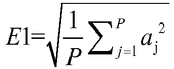
- Q denotes the number of counted traces (total number of trace gathers), P denotes the number of sampling points, and a j denotes an amplitude value;
- the method further comprises: 1) exciting and recording seismic wave data with a controllable seismic source; 2) recording with the controllable seismic source and making an absorption analysis in a selected time window, to obtain an amplitude spectrum of shot points or receiver points in the selected time window; 3) realizing an NMO correction processing by analyzing seismic propagation velocities.
- Step 202 stacking seismic trace gathers in a predetermined range among S seismic trace gathers to obtain a model trace, S being an integer.
- m1 and m2 denote serial numbers of the seismic trace gathers, and a ij denotes an amplitude value of a j-th sampling point of an i-th trace;
- m1, m2, i and j are all positive integers, 1 ⁇ m1 ⁇ m2 ⁇ S, i ⁇ [m1, m2].
- different serial numbers of the seismic trace gathers indicate that those seismic trace gathers are corresponding to different offsets; and the sampling points are selected from the amplitude spectrum at a predetermined time interval.
- the predetermined range [m1, m2] may be all or a part of the S seismic trace gathers.
- the amplitude value of a sampling point may be an average value of time positions of the seismic trace gather at the sampling point, or a value of any seismic trace of the seismic trace gather.
- Step 203 calculating a correlation coefficient of each seismic trace gather with the model trace, and selecting a K-th seismic trace gather with a maximum correlation coefficient.
- rx denotes a correlation coefficient of an x-th trace with the model trace
- a j denotes an amplitude value of an j-th sampling point of the model trace A
- Aa denotes an average amplitude value of the model trace A
- bj denotes an amplitude value of an j-th sampling point of the seismic trace gather B
- Ba denotes an average amplitude value of the seismic trace gather B
- Step 204 orderly calculating residual NMO correction amounts of the S seismic trace gathers.
- Step 204 is specifically realized in the following steps:
- the optimum position of each seismic trace gather is orderly sought from the K-th trace, a correlation coefficient of each seismic trace gather with the model trace is calculated through a sliding point by point in the seismic trace gather, a position is selected as an optimum point in the seismic trace gather when the correlation coefficient is the maximum, and a time shifting amount corresponding to the optimum point is ⁇ t.
- the selected K-th trace is taken as the model trace
- a previous trace is taken as a model trace of a current trace in turn, e.g., an (M+1) trace is taken as a model trace of an M-th trace
- an N-th trace is taken as a model trace of an (N+1)-th trace.
- rj denotes a correlation coefficient of a seismic trace gather with a model trace in a time window where an j-th sampling point is located
- a j denotes an amplitude value of an j-th sampling point in the model trace A
- Aa denotes an average amplitude value of the model trace A in the time window
- bj denotes an amplitude value of an j-th sampling point in the seismic trace gather B
- Ba denotes an average amplitude value of the seismic trace gather B in the time window
- the predetermined time range may be TO-dT to T1-dT
- the length of the time window may be T (T0 to T1)
- the specific values may be selected upon the actual demand.
- two slides of the time window are overlapped with each other, so that the selected optimum point has an enough accuracy.
- Step 205 performing a residual NMO correction of the S seismic trace gathers using the calculated residual NMO correction amounts of the S seismic trace gathers.
- a time shifting amount corresponding to an optimum point in each seismic trace gather is obtained as a correction amount ⁇ t at first; next, the NMO correction amount is taken as ⁇ t to correct each seismic trace gather.
- a method for processing seismic data comprises: stacking seismic trace gathers in a predetermined range among S seismic trace gathers after an NMO correction processing to obtain a model trace, S being an integer; calculating a correlation coefficient of each seismic trace gather with the model trace, and selecting a K-th seismic trace gather with a maximum correlation coefficient; calculating an optimum point of each seismic trace gather from the K-th seismic trace gather to two sides orderly; and performing a residual NMO correction of the seismic trace gathers according to the optimum points.
- calculating an optimum point of each seismic trace gather from the K-th seismic trace gather to two sides orderly specifically comprises: sliding a time window in a predetermined time range, calculating a correlation coefficient of a (K-1)-th seismic trace gather with the K-th seismic trace gather, selecting the time window as an optimal point when the correlation coefficient is the maximum, and taking a time shifting amount corresponding to the optimal point as a residual NMO correction amount of the (K-1)-th seismic trace gather, wherein K > 1 and K is an integer; sliding the time window in the predetermined time range, calculating a correlation coefficient of an M-th seismic trace gather and an (M+1) seismic trace gather, selecting the time window as an optimal point when the correlation coefficient is the maximum, and taking a time shifting amount corresponding to the optimal point as a residual NMO correction amount of the M-th seismic trace gather, wherein K-2 ⁇ M ⁇ 1 and M is an integer; sliding the time window in the predetermined time range, calculating a correlation coefficient of a (K+1)-th seismic trace gather with the
- performing a residual NMO correction of the seismic trace gathers according to the optimum points specifically comprises: performing a residual NMO correction of the S seismic trace gathers using the calculated residual NMO correction amounts of the S seismic trace gathers.
- Fig. 3a illustrates seismic trace gathers of a conventional seismic processing (NMO correction), in which it is apparent that amplitude energy (black part) of a seismic trace gather having a smaller shot-geophone distance (left side) is significantly weaker (the black part has a smaller width) than amplitude energy of a seismic trace gather having a larger shot-geophone distance (right side), and such an amplitude energy distribution obviously does not coincide with the distribution characteristics of the actual seismic reflection amplitude energy. Thus, an amplitude energy equalization processing needs to be performed.
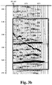
- Fig. 3b illustrates seismic trace gathers after an amplitude energy equalization processing.
- this solution is combined with the prior art which realizes an NMO correction processing by analyzing the seismic propagation velocities, so that events of all of the model trace gathers are corrected into a horizontal state, thereby eliminating the errors caused by the interpolation in the prior art, and improving the accuracy of the prestack NMO correction; thus the quality of the seismic data stack result after the trace gather optimization is obviously improved or increased, which can more accurately describe the stratum construction, the lithology and the fluid property.
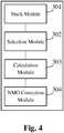
- Fig. 4 illustrates a structure diagram of an apparatus for processing seismic data provided by an embodiment of the present disclosure. As illustrated in Fig. 4 , the apparatus comprises:
- the embodiment of the present disclosure stacks a plurality of seismic trace gathers; calculates a correlation coefficient of each seismic trace gather with a model trace, and selects a K-th seismic trace gather; calculates an optimum point of each seismic trace gather from the K-th seismic trace gather to two sides orderly; and performs a residual NMO correction of the seismic trace gathers according to the optimum points.
- This solution is combined with the prior art which realizes an NMO correction processing by analyzing the seismic propagation velocities, so that events of all of the model trace gathers are corrected into a horizontal state, thereby eliminating the errors caused by the interpolation in the prior art, and improving the accuracy of the prestack NMO correction.
- Fig. 5 illustrates a structure diagram of another apparatus for processing seismic data provided by an embodiment of the present disclosure.
- the apparatus comprises: an equalization module 401 configured to perform an amplitude energy equalization processing of each seismic trace gather before stacking seismic trace gathers in a predetermined range among S seismic trace gathers after an NMO correction processing.
- Q denotes the number of counted traces
- P denotes the number of sampling points
- a j denotes an amplitude value
- a stack module 402 configured to stack the seismic trace gathers in the predetermined range among the S seismic trace gathers after the NMO correction processing to obtain a model trace, S being an integer; a selection module 403 configured to calculate a correlation coefficient of each seismic trace gather with the model trace, and select a K-th seismic trace gather with a maximum correlation coefficient; a calculation module 404 configured to slide a time window in a predetermined time range, calculate a correlation coefficient of a (K-1)-th seismic trace gather with the K-th seismic trace gather, select the time window as an optimum point when the correlation coefficient is the maximum, and take a time shifting amount corresponding to the optimum point as a residual NMO correction amount of the (K-1)-th seismic trace gather, wherein K > 1 and K is an integer; to slide the time window in the predetermined time range, calculate a correlation coefficient of an M-th seismic trace gather with an (M+1) seismic trace gather, select the time window as an optimum point when the correlation coefficient is the maximum, and take a time shifting amount corresponding
- the stack module 402 is configured to employ the following formula to stack the seismic trace gathers to obtain the model trace:
- m1 and m2 denote serial numbers of the seismic trace gathers, and a ij denotes an amplitude value of a j-th sampling point of an i-th trace;
- m1, m2, i and j are all positive integers, 1 ⁇ m1 ⁇ m2 ⁇ S, i ⁇ [m1, m2].
- rx denotes a correlation coefficient of an x-th trace with the model trace
- a j denotes an amplitude value of an j-th sampling point of the model trace A
- Aa denotes an average amplitude value of the model trace A
- bj denotes an amplitude value of an j-th sampling point of the seismic trace gather B
- Ba denotes an average amplitude value of the seismic trace gather B
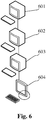
- Fig. 6 illustrates a structure diagram of still another apparatus for processing seismic data provided by an embodiment of the present disclosure.
- the apparatus for processing seismic data comprises: a first calculation unit 601, a second calculation unit 602, a third calculation unit 603, and a calibrator 604.
- the first calculation unit 601 is configured to stack seismic trace gathers in a predetermined range among S seismic trace gathers after an NMO correction processing to obtain a model trace, S being an integer;
- the second calculation unit 602 is configured to calculate a correlation coefficient of each seismic trace gather with the model trace, and select a K-th seismic trace gather with a maximum correlation coefficient;
- the third calculation unit 603 is configured to calculate an optimum point of each seismic trace gather from the K-th seismic trace gather to two sides orderly; and the calibrator 604 is configured to perform a residual NMO correction of the seismic trace gathers according to the optimum points.
- the third calculation unit 603 specifically comprises: a first calculation subunit, a second calculation subunit, a third calculation subunit, and a fourth calculation subunit.
- the first calculation subunit is configured to slide a time window in a predetermined time range, calculate a correlation coefficient of a (K-1)-th seismic trace gather with the K-th seismic trace gather, select the time window as an optimum point when the correlation coefficient is the maximum, and take a time shifting amount corresponding to the optimum point as a residual NMO correction amount of the (K-1)-th seismic trace gather, wherein K > 1 and K is an integer
- the second calculation subunit is configured to slide the time window in the predetermined time range, calculate a correlation coefficient of an M-th seismic trace gather with an (M+1) seismic trace gather, select the time window as an optimum point when the correlation coefficient is the maximum, and take a time shifting amount corresponding to the optimum point as a residual NMO correction amount of the M-th seismic trace gather, wherein K-2 ⁇ M ⁇ 1 and M is an integer
- the calibrator 604 specifically comprises an NMO correction subunit configured to perform a residual NMO correction of the S seismic trace gathers using the calculated residual NMO correction amounts of the S seismic trace gathers.
- Fig. 7 illustrates a structure diagram of yet another apparatus for processing seismic data provided by an embodiment of the present disclosure.
- the apparatus for processing seismic data comprises an equalizer 701, a first calculation unit 702, a second calculation unit 703, a third calculation unit 704 and a calibrator 705.
- the equalizer 701 is configured to perform an amplitude energy equalization processing of each seismic trace gather before stacking seismic trace gathers in a predetermined range among S seismic trace gathers after an NMO correction processing;
- the first calculation unit 702 is configured to stack the seismic trace gathers in the predetermined range among the S seismic trace gathers after the NMO correction processing to obtain a model trace, S being an integer;
- the second calculation unit 703 is configured to calculate a correlation coefficient of each seismic trace gather with the model trace, and select a K-th seismic trace gather with a maximum correlation coefficient;
- the third calculation unit 704 is configured to calculate an optimum point of each seismic trace gather from the K-th seismic trace gather to two sides orderly; and
- the calibrator 705 is configured to perform a residual NMO correction of the seismic trace gathers according to the optimum points.
- the embodiment of the present disclosure stacks a plurality of seismic trace gathers; calculates a correlation coefficient of each seismic trace gather with a model trace, and selects a K-th seismic trace gather; calculates an optimum point of each seismic trace gather from the K-th seismic trace gather to two sides orderly; and performs a residual NMO correction of the seismic trace gathers according to the optimum points.
Landscapes
- Engineering & Computer Science (AREA)
- Remote Sensing (AREA)
- Physics & Mathematics (AREA)
- Life Sciences & Earth Sciences (AREA)
- Acoustics & Sound (AREA)
- Environmental & Geological Engineering (AREA)
- Geology (AREA)
- General Life Sciences & Earth Sciences (AREA)
- General Physics & Mathematics (AREA)
- Geophysics (AREA)
- Geophysics And Detection Of Objects (AREA)
Abstract
Description
- The present disclosure claims priority of Chinese invention patent No.
CN201610204476.6 filed on April 1, 2016 - The seismic exploration technique explores the underground geological conditions by propagating an artificially excited seismic wave in the stratums. When a seismic wave excited at a certain place on the ground is propagated underground, reflection waves or refraction waves will be generated at stratum interfaces of different elasticity and returned to the ground surface. Special instruments may be used to record those waves and analyze the characteristics of the recorded waves (e.g., propagation time and vibration shapes of the waves), so as to accurately measure the depths and forms of those interfaces, and judge the lithology, physical properties and liquid-filled properties of the stratums.
- Since the seismic record is noisy, usually the seismic reflection waves of the same point underground are excited and received at different positions, and a set of those seismic reflection wave from the same point is referred to as a seismic trace gather. By stacking seismic signals, the noise can be eliminated and the signal-to-noise ratio can be improved.
- The same reflection point of seismic data collected in the field has different seismic reflection time which depends on the offset and the seismic propagation velocity, thus it is necessary to correct seismic record time of different offsets to a self-excitation and self-receiving seismic reflection time position, and this process is referred to as a Normal Move Out (NMO) correction, for the purpose of seismic signal stack.
- However, the propagation velocity of the seismic wave is unknown, thus an NMO correction is usually realized by designing a series of seismic propagation velocities to perform an NMO correction processing of the seismic trace gather.
- Since the volume of seismic data collected in the field is very huge, it is impossible for people to perform a velocity analysis for each seismic reflection point. Usually, a velocity analysis is performed for one seismic reflection point at an interval of several tens of traces, while a velocity of a trace gather without a velocity analysis is obtained by an interpolation of the velocity of the trace gather for which a velocity analysis has been performed. As the seismic velocities are not uniform, the interpolation velocities have certain errors more or less, and the NMO correction result cannot reach an ideal effect, thus it is difficult to correct the events of all of the seismic trace gathers into a horizontal state.
- In order to solve the problem of the prior art, the embodiments of the present disclosure provide a method and an apparatus for processing seismic data.
- The embodiments of the present disclosure provide a method for processing seismic data, comprising: stacking seismic trace gathers in a predetermined range among S seismic trace gathers after a Normal Move Out (NMO) correction processing to obtain a model trace, S being an integer; calculating a correlation coefficient of each seismic trace gather with the model trace, and selecting a K-th seismic trace gather with a maximum correlation coefficient; calculating an optimum point of each seismic trace gather from the K-th seismic trace gather to two sides orderly; and performing a residual NMO correction of the seismic trace gathers according to the optimum points.
- The embodiments of the present disclosure further provide an apparatus for processing seismic data, comprising: a first calculation unit configured to stack seismic trace gathers in a predetermined range among S seismic trace gathers after a Normal Move Out (NMO) correction processing to obtain a model trace, S being an integer; a second calculation unit configured to calculate a correlation coefficient of each seismic trace gather with the model trace, and select a K-th seismic trace gather with a maximum correlation coefficient; a third calculation unit configured to calculate an optimum point of each seismic trace gather from the K-th seismic trace gather to two sides orderly; and a calibrator configured to perform a residual NMO correction of the seismic trace gathers according to the optimum points.
- The technical solutions of the embodiments of the present disclosure achieve the following advantageous effects: by stacking a plurality of seismic trace gathers; calculating a correlation coefficient of each seismic trace gather with a model trace, and selecting a K-th seismic trace gather; calculating an optimum point of each seismic trace gather from the K-th seismic trace gather to two sides orderly; and performing a residual NMO correction of the seismic trace gathers according to the optimum points, this solution is combined with the prior art which realizes an NMO correction processing by analyzing the seismic propagation velocities, so that events of all of the model trace gathers are corrected into a horizontal state, thereby eliminating the errors caused by the interpolation in the prior art, and improving the accuracy of the prestack NMO correction.
- It shall be appreciated that the above general description and the following specific embodiments are just exemplary and illustrative, rather than limitations to the scope of the present disclosure.
- In order to more clearly describe the technical solutions in the embodiments of the present disclosure, the drawings to be used in the description of the embodiments will be briefly introduced as follows. Obviously, the drawings in the following description just illustrate some embodiments of the present disclosure, and a person skilled in the art can obtain other drawings from them without paying any creative effort.
-
Fig. 1 illustrates a flow diagram of a method for processing seismic data provided by an embodiment of the present disclosure; -
Fig. 2 illustrates a flow diagram of another method for processing seismic data provided by an embodiment of the present disclosure; -
Fig. 3a illustrates a schematic diagram of seismic trace gathers of a conventional seismic processing provided by an embodiment of the present disclosure; -
Fig. 3b illustrates a schematic diagram of seismic trace gathers after an amplitude energy equalization processing provided by an embodiment of the present disclosure; -
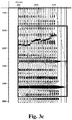
Fig. 3c illustrates a schematic diagram of seismic trace gathers after a residual NMO correction processing forFig. 3b provided by an embodiment of the present disclosure; -
Fig. 4 illustrates a structure diagram of an apparatus for processing seismic data provided by an embodiment of the present disclosure; -
Fig. 5 illustrates a structure diagram of another apparatus for processing seismic data provided by an embodiment of the present disclosure; -
Fig. 6 illustrates a structure diagram of still another apparatus for processing seismic data provided by an embodiment of the present disclosure; -
Fig. 7 illustrates a structure diagram of yet another apparatus for processing seismic data provided by an embodiment of the present disclosure. - In order that the objective, the technical solutions and the advantages of the embodiments of the present disclosure are clearer, the spirit of the revealed content of the present disclosure will be clearly explained as follows with reference to the drawings and detailed descriptions. After acquiring the embodiments of the present disclosure, any person skilled in the art can change and modify the technique taught by the present disclosure, without deviating from the spirit and range of the present disclosure.
-
Fig. 1 illustrates a flow diagram of a method for processing seismic data provided by an embodiment of the present disclosure. As illustrated inFig. 1 , the method comprises:
step 101: stacking seismic trace gathers in a predetermined range among S seismic trace gathers after a Normal Move Out (NMO) correction processing to obtain a model trace, S being an integer. - In which, the S seismic trace gathers are all Common Reflection Point (CRP) trace gathers, and common midpoint (CMP) trace gathers are recorded based on different offsets to obtain trace gathers of different serial numbers.
-
Fig. 3a illustrates a schematic diagram of seismic trace gathers, wherein a horizontal coordinate indicates an offset (unit: m), and each segment denotes an identical offset, while a vertical coordinate indicates time (unit: ms), and each segment denotes a seismic trace gather of an offset, which is a set of seismic traces of the offset. - In which, before
step 101, the seismic trace gathers have been processed in the manner of an NMO correction that analyzes the seismic propagation velocities. Specifically, a series of seismic wave stack velocities are estimated to calculate seismic reflection time; a difference value between the seismic reflection time and seismic reflection time of a seismic trace gather with an offset of 0 as an NMO correction amount; an NMO correction is performed for original seismic trace gathers; and it is observed to determine that a current seismic wave stack velocity is appropriate when the trace gathers reach a horizontal state at that seismic wave stack velocity. The observation process is usually completed by the operator with his naked eyes. - The seismic reflection time may be calculated in the following formula.

- In which, the predetermined range may mean all or a part of the S seismic trace gathers.
stacking the seismic trace gathers means adding amplitudes of the seismic trace gathers of different serial numbers together based on sampling points. - Step 102: calculating a correlation coefficient of each seismic trace gather with the model trace, and selecting a K-th seismic trace gather with a maximum correlation coefficient.
- Step 103: orderly calculating residual NMO correction amounts of the S seismic trace gathers.
- In which, the residual NMO correction amount means a correction amount used for a further correction processing of the seismic data after a processing is performed in the manner of an NMO correction that analyzes the seismic propagation velocities.
-
Step 103 is specifically realized in the following steps: - sliding a time window in a predetermined time range, calculating a correlation coefficient of a (K-1)-th seismic trace gather with the K-th seismic trace gather, selecting the time window as an optimum point when the correlation coefficient is the maximum, and taking a time shifting amount corresponding to the optimum point as a residual NMO correction amount of the (K-1)-th seismic trace gather, wherein K > 1 and K is an integer;
- sliding the time window in the predetermined time range, calculating a correlation coefficient of an M-th seismic trace gather with an (M+1) seismic trace gather, selecting the time window as an optimum point when the correlation coefficient is the maximum, and taking a time shifting amount corresponding to the optimum point as a residual NMO correction amount of the M-th seismic trace gather, wherein K-2≥M≥1 and M is an integer;
- sliding the time window in the predetermined time range, calculating a correlation coefficient of a (K+1)-th seismic trace gather with the K-th seismic trace gather, selecting the time window as an optimum point when the correlation coefficient is the maximum, and taking a time shifting amount corresponding to the optimum point as a residual NMO correction amount of the (K+1)-th seismic trace gather;
- sliding the time window in the predetermined time range, calculating a correlation coefficient of an (N+1)-th seismic trace gather with an N-th seismic trace gather, selecting the time window as an optimum point when the correlation coefficient is the maximum, and taking a time shifting amount corresponding to the optimum point as a residual NMO correction amount of the (N+1)-th seismic trace gather, wherein S-1≥N≥K+1 and N is an integer, and the time shifting amount corresponding to the optimum point is a difference value between seismic reflection time of a seismic trace gather (e.g., the (N+1)-th seismic trace gather herein) in the time window and seismic reflection time of a seismic trace gather with an offset of 0.
- In which, seismic reflection time of a seismic trace gather in the time window may be an average value of seismic reflection time of respective seismic traces of the seismic trace gather at the optimum point, or seismic reflection time of any one of the seismic traces.
- Step 104: performing a residual NMO correction of the S seismic trace gathers using the calculated residual NMO correction amounts of the S seismic trace gathers.
- In which, the residual NMO correction means a further correction processing of the seismic data after a processing is performed in the manner of an NMO correction that analyzes the seismic propagation velocities.
- In the embodiment of the present disclosure, by stacking a plurality of seismic trace gathers; calculating a correlation coefficient of each seismic trace gather with a model trace, and selecting a K-th seismic trace gather; calculating an optimum point of each seismic trace gather from the K-th seismic trace gather to two sides orderly; and performing a residual NMO correction of the seismic trace gathers according to the optimum points, this solution is combined with the prior art which realizes an NMO correction processing by analyzing the seismic propagation velocities, so that events of all of the model trace gathers are corrected into a horizontal state, thereby eliminating the errors caused by the interpolation in the prior art, and improving the accuracy of the prestack NMO correction.
-
Fig. 2 illustrates a flow diagram of another method for processing seismic data provided by an embodiment of the present disclosure. As illustrated inFig. 2 , the method comprises:
Step 201: performing an amplitude energy equalization processing of each seismic trace gather after an NMO correction processing. - In which, the amplitude energy equalization processing of each seismic trace gather is performed in the following steps:
first step: counting an amplitude energy E0 in a predetermined time window range (e.g., 1000 to 3000 ms):
- In which, Q denotes the number of counted traces (total number of trace gathers), P denotes the number of sampling points, and aj denotes an amplitude value;
second step: calculating an amplitude energy E1 of each seismic trace gather:
fourth step: performing an amplitude equalization processing of each seismic trace gather using the amplitude equalization coefficient:A ' =kA , whereinA denotes a sequence composed of amplitude values a of each seismic trace gather (amplitude values of a plurality of sampling points), andA ' denotes an amplitude value after the amplitude equalization processing. - Further, before
step 201, the method further comprises:
1) exciting and recording seismic wave data with a controllable seismic source; 2) recording with the controllable seismic source and making an absorption analysis in a selected time window, to obtain an amplitude spectrum of shot points or receiver points in the selected time window; 3) realizing an NMO correction processing by analyzing seismic propagation velocities. - Step 202: stacking seismic trace gathers in a predetermined range among S seismic trace gathers to obtain a model trace, S being an integer.
- Specifically, the following formula is employed to stack the seismic trace gathers in the predetermined range among the S seismic trace gathers after the NMO correction processing to obtain the model trace:

- In which, m1 and m2 denote serial numbers of the seismic trace gathers, and aij denotes an amplitude value of a j-th sampling point of an i-th trace; m1, m2, i and j are all positive integers, 1≤m1 < m2≤S, i∈ [m1, m2].
- In which, different serial numbers of the seismic trace gathers indicate that those seismic trace gathers are corresponding to different offsets; and the sampling points are selected from the amplitude spectrum at a predetermined time interval.
- In which, the predetermined range [m1, m2] may be all or a part of the S seismic trace gathers.
- In which, the amplitude value of a sampling point may be an average value of time positions of the seismic trace gather at the sampling point, or a value of any seismic trace of the seismic trace gather.
- Step 203: calculating a correlation coefficient of each seismic trace gather with the model trace, and selecting a K-th seismic trace gather with a maximum correlation coefficient.
- The following formula is employed to calculate a correlation coefficient of a model trace
A with a seismic trace gatherB :
- In which, rx denotes a correlation coefficient of an x-th trace with the model trace, aj denotes an amplitude value of an j-th sampling point of the model trace
A , Aa denotes an average amplitude value of the model traceA , bj denotes an amplitude value of an j-th sampling point of the seismic trace gatherB , and Ba denotes an average amplitude value of the seismic trace gatherB , wherein x and j are both positive integers, and 1 ≤x≤S. - Step 204: orderly calculating residual NMO correction amounts of the S seismic trace gathers.
- Step 204 is specifically realized in the following steps:
- sliding a time window in a predetermined time range, calculating a correlation coefficient of a (K-1)-th seismic trace gather with the K-th seismic trace gather, selecting the time window as an optimum point when the correlation coefficient is the maximum, and taking a time shifting amount corresponding to the optimum point as a residual NMO correction amount of the (K-1)-th seismic trace gather, wherein K > 1 and K is an integer;
- sliding the time window in the predetermined time range, calculating a correlation coefficient of an M-th seismic trace gather with an (M+1) seismic trace gather, selecting the time window as an optimum point when the correlation coefficient is the maximum, and taking a time shifting amount corresponding to the optimum point as a residual NMO correction amount of the M-th seismic trace gather, wherein K-2≥M≥1 and M is an integer;
- sliding the time window in the predetermined time range, calculating a correlation coefficient of a (K+1)-th seismic trace gather with the K-th seismic trace gather, selecting the time window as an optimum point when the correlation coefficient is the maximum, and taking a time shifting amount corresponding to the optimum point as a residual NMO correction amount of the (K+1)-th seismic trace gather;
- sliding the time window in the predetermined time range, calculating a correlation coefficient of an (N+1)-th seismic trace gather with an N-th seismic trace gather, selecting the time window as an optimum point when the correlation coefficient is the maximum, and taking a time shifting amount corresponding to the optimum point as a residual NMO correction amount of the (N+1)-th seismic trace gather, wherein S-1≥N≥K+1 and N is an integer, and the time shifting amount corresponding to the optimum point is a difference value between seismic reflection time of a seismic trace gather (e.g., the (N+1)-th seismic trace gather herein) in the time window and seismic reflection time of a seismic trace gather with an offset of 0.
- The optimum position of each seismic trace gather is orderly sought from the K-th trace, a correlation coefficient of each seismic trace gather with the model trace is calculated through a sliding point by point in the seismic trace gather, a position is selected as an optimum point in the seismic trace gather when the correlation coefficient is the maximum, and a time shifting amount corresponding to the optimum point is Δt. In the above calculation, firstly the selected K-th trace is taken as the model trace, while in subsequent calculations, a previous trace is taken as a model trace of a current trace in turn, e.g., an (M+1) trace is taken as a model trace of an M-th trace, and an N-th trace is taken as a model trace of an (N+1)-th trace.
- In which, a correlation coefficient of a seismic trace gather with a model trace in a time window is calculated as follows:

- In which,
rj denotes a correlation coefficient of a seismic trace gather with a model trace in a time window where an j-th sampling point is located, aj denotes an amplitude value of an j-th sampling point in the model traceA , Aa denotes an average amplitude value of the model traceA in the time window, bj denotes an amplitude value of an j-th sampling point in the seismic trace gatherB , and Ba denotes an average amplitude value of the seismic trace gatherB in the time window, wherein j is a positive integer. - In which, the predetermined time range may be TO-dT to T1-dT, the length of the time window may be T (T0 to T1), and the specific values may be selected upon the actual demand. In the above calculation, two slides of the time window are overlapped with each other, so that the selected optimum point has an enough accuracy.
- Step 205: performing a residual NMO correction of the S seismic trace gathers using the calculated residual NMO correction amounts of the S seismic trace gathers.
- Specifically, a time shifting amount corresponding to an optimum point in each seismic trace gather is obtained as a correction amount Δt at first; next, the NMO correction amount is taken as Δt to correct each seismic trace gather.
- In another embodiment of the present disclosure, a method for processing seismic data comprises: stacking seismic trace gathers in a predetermined range among S seismic trace gathers after an NMO correction processing to obtain a model trace, S being an integer; calculating a correlation coefficient of each seismic trace gather with the model trace, and selecting a K-th seismic trace gather with a maximum correlation coefficient; calculating an optimum point of each seismic trace gather from the K-th seismic trace gather to two sides orderly; and performing a residual NMO correction of the seismic trace gathers according to the optimum points.
- Further, calculating an optimum point of each seismic trace gather from the K-th seismic trace gather to two sides orderly specifically comprises: sliding a time window in a predetermined time range, calculating a correlation coefficient of a (K-1)-th seismic trace gather with the K-th seismic trace gather, selecting the time window as an optimal point when the correlation coefficient is the maximum, and taking a time shifting amount corresponding to the optimal point as a residual NMO correction amount of the (K-1)-th seismic trace gather, wherein K > 1 and K is an integer; sliding the time window in the predetermined time range, calculating a correlation coefficient of an M-th seismic trace gather and an (M+1) seismic trace gather, selecting the time window as an optimal point when the correlation coefficient is the maximum, and taking a time shifting amount corresponding to the optimal point as a residual NMO correction amount of the M-th seismic trace gather, wherein K-2≥M≥1 and M is an integer; sliding the time window in the predetermined time range, calculating a correlation coefficient of a (K+1)-th seismic trace gather with the K-th seismic trace gather, selecting the time window as an optimal point when the correlation coefficient is the maximum, and taking a time shifting amount corresponding to the optimal point as a residual NMO correction amount of the (K+1)-th seismic trace gather; sliding the time window in the predetermined time range, calculating a correlation coefficient of an (N+1)-th seismic trace gather with an N-th seismic trace gather, selecting the time window as an optimum point when the correlation coefficient is the maximum, and taking a time shifting amount corresponding to the optimum point as a residual NMO correction amount of the (N+1)-th seismic trace gather, wherein S-1≥N≥K+1 and N is an integer, and the time shifting amount corresponding to the optimum point is a difference value between seismic reflection time of a seismic trace gather in the time window and seismic reflection time of a seismic trace gather with an offset of 0.
- Further, performing a residual NMO correction of the seismic trace gathers according to the optimum points specifically comprises: performing a residual NMO correction of the S seismic trace gathers using the calculated residual NMO correction amounts of the S seismic trace gathers.
- Next, the effects of the method provided by the embodiment of the present disclosure are described as follows with reference to
Figs. 3a to 3c . -
Fig. 3a illustrates seismic trace gathers of a conventional seismic processing (NMO correction), in which it is apparent that amplitude energy (black part) of a seismic trace gather having a smaller shot-geophone distance (left side) is significantly weaker (the black part has a smaller width) than amplitude energy of a seismic trace gather having a larger shot-geophone distance (right side), and such an amplitude energy distribution obviously does not coincide with the distribution characteristics of the actual seismic reflection amplitude energy. Thus, an amplitude energy equalization processing needs to be performed.Fig. 3b illustrates seismic trace gathers after an amplitude energy equalization processing. Since the events of the trace gathers are uneven, the variation characteristics of the amplitude along with the offset cannot be correctly represented just through the amplitude energy equalization processing, and a residual NMO correction processing of the model trace shall also be performed, so as to correct the events of the prestack trace gathers into a horizontal state (Fig. 3c ). - In the embodiment of the present disclosure, by stacking a plurality of seismic trace gathers; calculating a correlation coefficient of each seismic trace gather with a model trace, and selecting a K-th seismic trace gather; calculating an optimum point of each seismic trace gather from the K-th seismic trace gather to two sides orderly; and performing a residual NMO correction of the seismic trace gathers according to the optimum points, this solution is combined with the prior art which realizes an NMO correction processing by analyzing the seismic propagation velocities, so that events of all of the model trace gathers are corrected into a horizontal state, thereby eliminating the errors caused by the interpolation in the prior art, and improving the accuracy of the prestack NMO correction; thus the quality of the seismic data stack result after the trace gather optimization is obviously improved or increased, which can more accurately describe the stratum construction, the lithology and the fluid property.
-
Fig. 4 illustrates a structure diagram of an apparatus for processing seismic data provided by an embodiment of the present disclosure. As illustrated inFig. 4 , the apparatus comprises: - a
stack module 301 configured to stack seismic trace gathers in a predetermined range among S seismic trace gathers after an NMO correction processing to obtain a model trace, S being an integer; - a
selection module 302 configured to calculate a correlation coefficient of each seismic trace gather with the model trace, and select a K-th seismic trace gather with a maximum correlation coefficient; - a
calculation module 303 configured to slide a time window in a predetermined time range, calculate a correlation coefficient of a (K-1)-th seismic trace gather with the K-th seismic trace gather, select the time window as an optimum point when the correlation coefficient is the maximum, and take a time shifting amount corresponding to the optimum point as a residual NMO correction amount of the (K-1)-th seismic trace gather, wherein K > 1 and K is an integer; - to slide the time window in the predetermined time range, calculate a correlation coefficient of an M-th seismic trace gather with an (M+1) seismic trace gather, select the time window as an optimum point when the correlation coefficient is the maximum, and take a time shifting amount corresponding to the optimum point as a residual NMO correction amount of the M-th seismic trace gather, wherein K-2≥M≥1 and M is an integer;
- to slide the time window in the predetermined time range, calculate a correlation coefficient of a (K+1)-th seismic trace gather with the K-th seismic trace gather, select the time window as an optimum point when the correlation coefficient is the maximum, and take a time shifting amount corresponding to the optimum point as a residual NMO correction amount of the (K+1)-th seismic trace gather;
- to slide the time window in the predetermined time range, calculate a correlation coefficient of an (N+1)-th seismic trace gather with an N-th seismic trace gather, select the time window as an optimum point when the correlation coefficient is the maximum, and take a time shifting amount corresponding to the optimum point as a residual NMO correction amount of the (N+1)-th seismic trace gather, wherein S-1≥N≥K+1 and N is an integer, and the time shifting amount corresponding to the optimum point is a difference value between seismic reflection time of a seismic trace gather (e.g., the (N+1)-th seismic trace gather herein) in the time window and seismic reflection time of a seismic trace gather with an offset of 0;
- an
NMO correction module 304 configured to perform a residual NMO correction of the S seismic trace gathers using the calculated residual NMO correction amounts of the S seismic trace gathers. - The embodiment of the present disclosure stacks a plurality of seismic trace gathers; calculates a correlation coefficient of each seismic trace gather with a model trace, and selects a K-th seismic trace gather; calculates an optimum point of each seismic trace gather from the K-th seismic trace gather to two sides orderly; and performs a residual NMO correction of the seismic trace gathers according to the optimum points. This solution is combined with the prior art which realizes an NMO correction processing by analyzing the seismic propagation velocities, so that events of all of the model trace gathers are corrected into a horizontal state, thereby eliminating the errors caused by the interpolation in the prior art, and improving the accuracy of the prestack NMO correction.
-
Fig. 5 illustrates a structure diagram of another apparatus for processing seismic data provided by an embodiment of the present disclosure. As illustrated inFig. 5 , the apparatus comprises:
anequalization module 401 configured to perform an amplitude energy equalization processing of each seismic trace gather before stacking seismic trace gathers in a predetermined range among S seismic trace gathers after an NMO correction processing. - In another implementation of the embodiment of the present disclosure, the
equalization module 401 is configured to:
count an amplitude energy E0 in a predetermined time window range:
- In which, Q denotes the number of counted traces, P denotes the number of sampling points, and aj denotes an amplitude value;
calculate an amplitude energy E1 of each seismic trace gather:
perform an amplitude equalization processing of each seismic trace gather using the amplitude equalization coefficient:A ' =kA , whereinA denotes a sequence composed of amplitude values a of each seismic trace gather (amplitude values of a plurality of sampling points), andA ' denotes an amplitude value after the amplitude equalization processing.
astack module 402 configured to stack the seismic trace gathers in the predetermined range among the S seismic trace gathers after the NMO correction processing to obtain a model trace, S being an integer;
aselection module 403 configured to calculate a correlation coefficient of each seismic trace gather with the model trace, and select a K-th seismic trace gather with a maximum correlation coefficient;
acalculation module 404 configured to slide a time window in a predetermined time range, calculate a correlation coefficient of a (K-1)-th seismic trace gather with the K-th seismic trace gather, select the time window as an optimum point when the correlation coefficient is the maximum, and take a time shifting amount corresponding to the optimum point as a residual NMO correction amount of the (K-1)-th seismic trace gather, wherein K > 1 and K is an integer;
to slide the time window in the predetermined time range, calculate a correlation coefficient of an M-th seismic trace gather with an (M+1) seismic trace gather, select the time window as an optimum point when the correlation coefficient is the maximum, and take a time shifting amount corresponding to the optimum point as a residual NMO correction amount of the M-th seismic trace gather, wherein K-2≥M≥1 and M is an integer;
to slide the time window in the predetermined time range, calculate a correlation coefficient of a (K+1)-th seismic trace gather with the K-th seismic trace gather, select the time window as an optimum point when the correlation coefficient is the maximum, and take a time shifting amount corresponding to the optimum point as a residual NMO correction amount of the (K+1)-th seismic trace gather;
to slide the time window in the predetermined time range, calculate a correlation coefficient of an (N+1)-th seismic trace gather with an N-th seismic trace gather, select the time window as an optimum point when the correlation coefficient is the maximum, and take a time shifting amount corresponding to the optimum point as a residual NMO correction amount of the (N+1)-th seismic trace gather, wherein S-1≥N≥K+1 and N is an integer, and the time shifting amount corresponding to the optimum point is a difference value between seismic reflection time of a seismic trace gather (e.g., the (N+1)-th seismic trace gather herein) in the time window and seismic reflection time of a seismic trace gather with an offset of 0;
anNMO correction module 405 configured to perform a residual NMO correction of the S seismic trace gathers using the calculated residual NMO correction amounts of the S seismic trace gathers. - In an implementation of the embodiment of the present disclosure, the
stack module 402 is configured to employ the following formula to stack the seismic trace gathers to obtain the model trace:
- In which, m1 and m2 denote serial numbers of the seismic trace gathers, and aij denotes an amplitude value of a j-th sampling point of an i-th trace; m1, m2, i and j are all positive integers, 1≤m1 < m2≤S, i∈ [m1, m2].
- In another implementation of the embodiment of the present disclosure, the
selection module 403 is configured to:
employ the following formula to calculate a correlation coefficient of a model traceA with a seismic trace gatherB :
- In which,
rx denotes a correlation coefficient of an x-th trace with the model trace, aj denotes an amplitude value of an j-th sampling point of the model traceA , Aa denotes an average amplitude value of the model traceA , bj denotes an amplitude value of an j-th sampling point of the seismic trace gatherB , and Ba denotes an average amplitude value of the seismic trace gatherB , wherein x and j are both positive integers, and 1 ≤x≤S. -
Fig. 6 illustrates a structure diagram of still another apparatus for processing seismic data provided by an embodiment of the present disclosure. As illustrated inFig. 6 , the apparatus for processing seismic data comprises: afirst calculation unit 601, asecond calculation unit 602, athird calculation unit 603, and acalibrator 604. In which, thefirst calculation unit 601 is configured to stack seismic trace gathers in a predetermined range among S seismic trace gathers after an NMO correction processing to obtain a model trace, S being an integer; thesecond calculation unit 602 is configured to calculate a correlation coefficient of each seismic trace gather with the model trace, and select a K-th seismic trace gather with a maximum correlation coefficient; thethird calculation unit 603 is configured to calculate an optimum point of each seismic trace gather from the K-th seismic trace gather to two sides orderly; and thecalibrator 604 is configured to perform a residual NMO correction of the seismic trace gathers according to the optimum points. - Further, the
third calculation unit 603 specifically comprises: a first calculation subunit, a second calculation subunit, a third calculation subunit, and a fourth calculation subunit. In which, the first calculation subunit is configured to slide a time window in a predetermined time range, calculate a correlation coefficient of a (K-1)-th seismic trace gather with the K-th seismic trace gather, select the time window as an optimum point when the correlation coefficient is the maximum, and take a time shifting amount corresponding to the optimum point as a residual NMO correction amount of the (K-1)-th seismic trace gather, wherein K > 1 and K is an integer; the second calculation subunit is configured to slide the time window in the predetermined time range, calculate a correlation coefficient of an M-th seismic trace gather with an (M+1) seismic trace gather, select the time window as an optimum point when the correlation coefficient is the maximum, and take a time shifting amount corresponding to the optimum point as a residual NMO correction amount of the M-th seismic trace gather, wherein K-2≥M≥1 and M is an integer; the third calculation subunit is configured to slide the time window in the predetermined time range, calculate a correlation coefficient of a (K+1)-th seismic trace gather with the K-th seismic trace gather, select the time window as an optimum point when the correlation coefficient is the maximum, and take a time shifting amount corresponding to the optimum point as a residual NMO correction amount of the (K+1)-th seismic trace gather; and the fourth calculation subunit is configured to slide the time window in the predetermined time range, calculate a correlation coefficient of an (N+1)-th seismic trace gather with an N-th seismic trace gather, select the time window as an optimum point when the correlation coefficient is the maximum, and take a time shifting amount corresponding to the optimum point as a residual NMO correction amount of the (N+1)-th seismic trace gather, wherein S-1≥N≥K+1 and N is an integer, and the time shifting amount corresponding to the optimum point is a difference value between seismic reflection time of a seismic trace gather in the time window and seismic reflection time of a seismic trace gather with an offset of 0. - Further, the
calibrator 604 specifically comprises an NMO correction subunit configured to perform a residual NMO correction of the S seismic trace gathers using the calculated residual NMO correction amounts of the S seismic trace gathers. -
Fig. 7 illustrates a structure diagram of yet another apparatus for processing seismic data provided by an embodiment of the present disclosure. As illustrated inFig. 7 , the apparatus for processing seismic data comprises anequalizer 701, afirst calculation unit 702, asecond calculation unit 703, athird calculation unit 704 and acalibrator 705. In which, theequalizer 701 is configured to perform an amplitude energy equalization processing of each seismic trace gather before stacking seismic trace gathers in a predetermined range among S seismic trace gathers after an NMO correction processing; thefirst calculation unit 702 is configured to stack the seismic trace gathers in the predetermined range among the S seismic trace gathers after the NMO correction processing to obtain a model trace, S being an integer; thesecond calculation unit 703 is configured to calculate a correlation coefficient of each seismic trace gather with the model trace, and select a K-th seismic trace gather with a maximum correlation coefficient; thethird calculation unit 704 is configured to calculate an optimum point of each seismic trace gather from the K-th seismic trace gather to two sides orderly; and thecalibrator 705 is configured to perform a residual NMO correction of the seismic trace gathers according to the optimum points. - The embodiment of the present disclosure stacks a plurality of seismic trace gathers; calculates a correlation coefficient of each seismic trace gather with a model trace, and selects a K-th seismic trace gather; calculates an optimum point of each seismic trace gather from the K-th seismic trace gather to two sides orderly; and performs a residual NMO correction of the seismic trace gathers according to the optimum points. This solution is combined with the prior art which realizes an NMO correction processing by analyzing the seismic propagation velocities, so that events of all of the model trace gathers are corrected into a horizontal state, thereby eliminating the errors caused by the interpolation in the prior art, and improving the accuracy of the prestack NMO correction; thus the quality of the seismic data stack result after the trace gather optimization is obviously improved or increased, which can more accurately describe the stratum construction, the lithology and the fluid property.
- A person skilled in the art will appreciate that all or a part of the steps of those embodiments may be completed by hardware, or by instructing relevant hardware through a program that may be stored in a computer readable storage medium such as a read-only memory, a magnetic disk or an optical disk.
- Those described above are just preferred embodiments of the present disclosure, rather than limitations thereto. Any amendment, equivalent replacement, improvement, etc. made within the spirit and principle of the present disclosure shall fall within the protection scope of the present disclosure.
Claims (14)
- A method for processing seismic data, comprising:stacking seismic trace gathers in a predetermined range among S seismic trace gathers after a Normal Move Out (NMO) correction processing to obtain a model trace, S being an integer;calculating a correlation coefficient of each seismic trace gather with the model trace, and selecting a K-th seismic trace gather with a maximum correlation coefficient;calculating an optimum point of each seismic trace gather from the K-th seismic trace gather to two sides orderly; andperforming a residual NMO correction of the seismic trace gathers according to the optimum points.
- The method according to claim 1, wherein calculating an optimum point of each seismic trace gather from the K-th seismic trace gather to two sides orderly comprises:sliding a time window in a predetermined time range, calculating a correlation coefficient of a (K-1)-th seismic trace gather with the K-th seismic trace gather, selecting the time window as an optimal point when the correlation coefficient is the maximum, and taking a time shifting amount corresponding to the optimal point as a residual NMO correction amount of the (K-1)-th seismic trace gather, wherein K > 1 and K is an integer;sliding the time window in the predetermined time range, calculating a correlation coefficient of an M-th seismic trace gather with an (M+1) seismic trace gather, selecting the time window as an optimal point when the correlation coefficient is the maximum, and taking a time shifting amount corresponding to the optimal point as a residual NMO correction amount of the M-th seismic trace gather, wherein K-2≥M≥1 and M is an integer;sliding the time window in the predetermined time range, calculating a correlation coefficient of a (K+1)-th seismic trace gather with the K-th seismic trace gather, selecting the time window as an optimal point when the correlation coefficient is the maximum, and taking a time shifting amount corresponding to the optimal point as a residual NMO correction amount of the (K+1)-th seismic trace gather; andsliding the time window in the predetermined time range, calculating a correlation coefficient of an (N+1)-th seismic trace gather with an N-th seismic trace gather, selecting the time window as an optimum point when the correlation coefficient is the maximum, and taking a time shifting amount corresponding to the optimum point as a residual NMO correction amount of the (N+1)-th seismic trace gather, wherein S-1≥N≥K+1 and N is an integer, and the time shifting amount corresponding to the optimum point is a difference value between seismic reflection time of a seismic trace gather in the time window and seismic reflection time of a seismic trace gather with an offset of 0.
- The method according to claim 2, wherein performing a residual NMO correction of the seismic trace gathers according to the optimum points comprises:
performing a residual NMO correction of the S seismic trace gathers using the calculated residual NMO correction amounts of the S seismic trace gathers. - The method according to claim 1, wherein stacking seismic trace gathers in a predetermined range among S seismic trace gathers after an NMO correction processing to obtain a model trace comprises:
employing the following formula to stack the seismic trace gathers to obtain the model trace: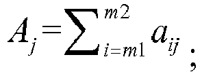
- The method according to claim 1, wherein calculating a correlation coefficient of each seismic trace gather with the model trace comprises:
employing the following formula to calculate a correlation coefficient of a model traceA with a seismic trace gatherB :
rx denotes a correlation coefficient of an x-th trace with the model trace, aj denotes an amplitude value of an j-th sampling point of the model traceA , Aa denotes an average amplitude value of the model traceA , bj denotes an amplitude value of an j-th sampling point of the seismic trace gatherB , and Ba denotes an average amplitude value of the seismic trace gatherB ; x and j are both positive integers, and 1≤x≤S. - The method according to any one of claims 1 to 5, wherein before stacking seismic trace gathers in a predetermined range among S seismic trace gathers after an NMO correction processing to obtain a model trace, the method further comprises:
performing an amplitude energy equalization processing of each seismic trace gather. - The method according to claim 6, wherein performing an amplitude energy equalization processing of each seismic trace gather comprises:counting an amplitude energy E0 in a predetermined time window range:
 calculating an amplitude energy E1 of each seismic trace gather:
 calculating an amplitude equalization coefficient k of each seismic trace gather:
 performing an amplitude equalization processing of each seismic trace gather using the amplitude equalization coefficient:
A' denotes a sequence composed of amplitude values a of each seismic trace gather, andA ' denotes an amplitude value after the amplitude equalization processing. - An apparatus for processing seismic data, comprising:a first calculation unit configured to stack seismic trace gathers in a predetermined range among S seismic trace gathers after a Normal Move Out (NMO) correction processing to obtain a model trace, S being an integer;a second calculation unit configured to calculate a correlation coefficient of each seismic trace gather with the model trace, and select a K-th seismic trace gather with a maximum correlation coefficient;a third calculation unit configured to calculate an optimum point of each seismic trace gather from the K-th seismic trace gather to two sides orderly; anda calibrator configured to perform a residual NMO correction of the seismic trace gathers according to the optimum points.
- The apparatus according to claim 8, wherein the third calculation unit comprises:a first calculation subunit configured to slide a time window in a predetermined time range, calculate a correlation coefficient of a (K-1)-th seismic trace gather with the K-th seismic trace gather, select the time window as an optimum point when the correlation coefficient is the maximum, and take a time shifting amount corresponding to the optimum point as a residual NMO correction amount of the (K-1)-th seismic trace gather, wherein K > 1 and K is an integer;a second calculation subunit configured to slide the time window in the predetermined time range, calculate a correlation coefficient of an M-th seismic trace gather with an (M+1) seismic trace gather, select the time window as an optimum point when the correlation coefficient is the maximum, and take a time shifting amount corresponding to the optimum point as a residual NMO correction amount of the M-th seismic trace gather, wherein K-2≥M≥ 1 and M is an integer;a third calculation subunit is configured to slide the time window in the predetermined time range, calculate a correlation coefficient of a (K+1)-th seismic trace gather with the K-th seismic trace gather, select the time window as an optimum point when the correlation coefficient is the maximum, and take a time shifting amount corresponding to the optimum point as a residual NMO correction amount of the (K+1)-th seismic trace gather; anda fourth calculation subunit is configured to slide the time window in the predetermined time range, calculate a correlation coefficient of an (N+1)-th seismic trace gather with an N-th seismic trace gather, select the time window as an optimum point when the correlation coefficient is the maximum, and take a time shifting amount corresponding to the optimum point as a residual NMO correction amount of the (N+1)-th seismic trace gather, wherein S-1≥ N≥K+1 and N is an integer, and the time shifting amount corresponding to the optimum point is a difference value between seismic reflection time of a seismic trace gather in the time window and seismic reflection time of a seismic trace gather with an offset of 0.
- The apparatus according to claim 9, wherein the calibrator comprises:
an NMO correction subunit configured to perform a residual NMO correction of the S seismic trace gathers using the calculated residual NMO correction amounts of the S seismic trace gathers. - The apparatus according to claim 8, wherein the first calculation unit is configured to:
employ the following formula to stack the seismic trace gathers to obtain the model trace:
- The apparatus according to claim 8, wherein the second calculation unit is configured to:
employ the following formula to calculate a correlation coefficient of a model traceA with a seismic trace gatherB :
A , Aa denotes an average amplitude value of the model traceA , bj denotes an amplitude value of an j-th sampling point of the seismic trace gatherB , and Ba denotes an average amplitude value of the seismic trace gatherB ; x and j are both positive integers, and 1≤x≤S. - The apparatus according to any one of claims 8 to 12, further comprising:
an equalizer configured to perform an amplitude energy equalization processing of each seismic trace gather before stacking seismic trace gathers in a predetermined range among S seismic trace gathers after an NMO correction processing to obtain a model trace. - The apparatus according to claim 13, wherein the equalizer is configured to:count an amplitude energy E0 in a predetermined time window range:
 calculate an amplitude energy E1 of each seismic trace gather:
 calculate an amplitude equalization coefficient k of each seismic trace gather:
 perform an amplitude equalization processing of each seismic trace gather using the amplitude equalization coefficient:
A denotes a sequence composed of amplitude values a of each seismic trace gather, andA ' denotes an amplitude value after the amplitude equalization processing.
Applications Claiming Priority (2)
| Application Number | Priority Date | Filing Date | Title |
|---|---|---|---|
| CN201610204476.6A CN106226818B (en) | 2016-04-01 | 2016-04-01 | Seismic data processing method and device |
| PCT/CN2017/078498 WO2017167191A1 (en) | 2016-04-01 | 2017-03-29 | Method and device for processing seismic data |
Publications (3)
| Publication Number | Publication Date |
|---|---|
| EP3324216A1 true EP3324216A1 (en) | 2018-05-23 |
| EP3324216A4 EP3324216A4 (en) | 2018-10-17 |
| EP3324216B1 EP3324216B1 (en) | 2020-08-05 |
Family
ID=57519258
Family Applications (1)
| Application Number | Title | Priority Date | Filing Date |
|---|---|---|---|
| EP17773221.1A Active EP3324216B1 (en) | 2016-04-01 | 2017-03-29 | Method and device for processing seismic data |
Country Status (5)
| Country | Link |
|---|---|
| US (1) | US10705238B2 (en) |
| EP (1) | EP3324216B1 (en) |
| CN (1) | CN106226818B (en) |
| RU (1) | RU2694621C1 (en) |
| WO (1) | WO2017167191A1 (en) |
Families Citing this family (20)
| Publication number | Priority date | Publication date | Assignee | Title |
|---|---|---|---|---|
| CN106226818B (en) * | 2016-04-01 | 2018-05-04 | 中国石油天然气股份有限公司 | Seismic data processing method and device |
| CN107607993B (en) * | 2017-09-07 | 2019-05-31 | 中国石油大学(北京) | A method, device and system for determining superposition speed |
| CN107843919B (en) * | 2017-10-27 | 2020-02-07 | 中国石油天然气集团有限公司 | Micro-seismic monitoring data amplitude equalization method |
| CN110609326A (en) * | 2018-06-15 | 2019-12-24 | 中国石油化工股份有限公司 | Method and system for automatic leveling of seismic gathers |
| CN110618457B (en) * | 2018-06-20 | 2021-02-26 | 中国石油化工股份有限公司 | Combined denoising method and device for vibroseis seismic data |
| CN110824566B (en) * | 2018-08-10 | 2021-09-28 | 中国石油天然气股份有限公司 | Seismic attribute fusion method and device and storage medium |
| CN112180446B (en) * | 2019-07-04 | 2024-07-26 | 中国石油天然气集团有限公司 | Method and device for overlapping three-dimensional seismic data pre-stack gathers |
| CN112230285B (en) * | 2019-07-15 | 2023-09-26 | 中国石油天然气集团有限公司 | Correction method and correction device for earthquake data excitation delay time |
| CN112305593B (en) * | 2019-07-23 | 2023-07-25 | 中国石油天然气集团有限公司 | Abnormal first arrival identification method and device |
| CN112649873B (en) * | 2019-10-10 | 2024-04-09 | 中国石油化工股份有限公司 | Seismic data frequency division motion correction processing method and system |
| CN112666601B (en) * | 2019-10-15 | 2024-03-22 | 中国石油化工股份有限公司 | Method and system for fitting effective time window to seismic data amplitude |
| CN112882102B (en) * | 2019-11-29 | 2024-05-28 | 中国石油天然气集团有限公司 | Seismic noise attenuation method and device |
| CN114002741B (en) * | 2020-07-28 | 2024-01-30 | 中国石油天然气股份有限公司 | Pre-stack depth migration method and device and computer readable storage medium |
| CN114114418B (en) * | 2020-08-28 | 2024-06-18 | 中国石油化工股份有限公司 | Seismic signal gain method, apparatus, computer device and storage medium |
| CN114325833A (en) * | 2022-01-05 | 2022-04-12 | 中国海洋大学 | A method for suppressing outliers in sub-bands of seismic records |
| CN119310627A (en) * | 2023-07-13 | 2025-01-14 | 中国石油化工股份有限公司 | Prestack gather optimization method based on dynamic image deformation |
| CN119846715B (en) * | 2023-10-16 | 2025-11-07 | 中国石油化工股份有限公司 | Five-dimensional seismic trace set leveling correction method and device based on two-step method |
| CN119937016B (en) * | 2023-11-03 | 2025-10-28 | 中国石油天然气集团有限公司 | Seismic data correction method, device, equipment and storage medium |
| CN120233428B (en) * | 2023-12-28 | 2026-05-01 | 中国石油天然气集团有限公司 | Pre-stack connected energy adjustment method, device, equipment and storage medium |
| CN120294835B (en) * | 2025-05-28 | 2025-09-26 | 广东省地质调查研究院 | Method, system, equipment and storage medium for picking up speed of refraction wave |
Family Cites Families (16)
| Publication number | Priority date | Publication date | Assignee | Title |
|---|---|---|---|---|
| US4203161A (en) * | 1972-03-01 | 1980-05-13 | Texaco Inc. | Method of enhancing common depth point seismic data |
| FR2726091B1 (en) * | 1994-10-19 | 1996-12-20 | Elf Aquitaine | METHOD OF ANALYSIS AND TREATMENT OF SEISMIC DATA REFLECTION FOR THE DETERMINATION OF A FINE SPEED FIELD FOR CORRECTION OF HYPERBOLICITY |
| GB9726928D0 (en) * | 1997-12-19 | 1998-02-18 | Geco Prakla Uk Ltd | Method of stacking seismic signals |
| CN1129008C (en) * | 2001-06-29 | 2003-11-26 | 中国石油天然气股份有限公司 | A Method of Dynamic and Static Correction with Model Constraints |
| US20030187583A1 (en) * | 2002-04-01 | 2003-10-02 | Martin Federico D. | Method and apparatus for resolving shear wave seismic data |
| US7496452B2 (en) * | 2007-04-13 | 2009-02-24 | Westerngeco L.L.C. | Correction for errors caused by variation in water conditions |
| US9075162B2 (en) * | 2011-11-10 | 2015-07-07 | Pgs Geophysical As | Method and system for separating seismic sources in marine simultaneous shooting acquisition |
| CN102540252B (en) * | 2011-12-15 | 2014-08-06 | 中国石油集团川庆钻探工程有限公司地球物理勘探公司 | High-precision median stacking method on basis of cross-correlation |
| CN102565857B (en) * | 2011-12-16 | 2014-09-10 | 中国石油集团川庆钻探工程有限公司地球物理勘探公司 | Automatic remaining dynamic correction method |
| CN102879821B (en) * | 2012-09-26 | 2015-01-21 | 中国石油天然气股份有限公司 | A Fine Event Flattening Method for Seismic Prestack Gathers |
| US9857490B2 (en) * | 2013-12-30 | 2018-01-02 | Pgs Geophysical As | Methods and systems for optimizing generation of seismic images |
| US11175421B2 (en) * | 2014-01-10 | 2021-11-16 | Cgg Services Sas | Device and method for mitigating cycle-skipping in full waveform inversion |
| CN104181588B (en) * | 2014-08-15 | 2016-08-31 | 中国石油集团川庆钻探工程有限公司地球物理勘探公司 | A kind of method building high-quality model trace |
| CN104459764B (en) * | 2014-11-20 | 2017-02-01 | 天津大学 | Linkage electromagnetic hammer applicable to researching multi-point seismic oscillation in laboratory |
| CN104459794B (en) * | 2014-12-01 | 2017-02-22 | 郑鸿明 | Common-reflection-point gather time-variable time difference correction method and device |
| CN106226818B (en) * | 2016-04-01 | 2018-05-04 | 中国石油天然气股份有限公司 | Seismic data processing method and device |
-
2016
- 2016-04-01 CN CN201610204476.6A patent/CN106226818B/en active Active
-
2017
- 2017-03-29 WO PCT/CN2017/078498 patent/WO2017167191A1/en not_active Ceased
- 2017-03-29 EP EP17773221.1A patent/EP3324216B1/en active Active
- 2017-03-29 RU RU2018105481A patent/RU2694621C1/en active
-
2018
- 2018-01-29 US US15/882,779 patent/US10705238B2/en active Active
Also Published As
| Publication number | Publication date |
|---|---|
| EP3324216B1 (en) | 2020-08-05 |
| US10705238B2 (en) | 2020-07-07 |
| CN106226818A (en) | 2016-12-14 |
| EP3324216A4 (en) | 2018-10-17 |
| CN106226818B (en) | 2018-05-04 |
| WO2017167191A1 (en) | 2017-10-05 |
| RU2694621C1 (en) | 2019-07-16 |
| US20180149764A1 (en) | 2018-05-31 |
Similar Documents
| Publication | Publication Date | Title |
|---|---|---|
| EP3324216B1 (en) | Method and device for processing seismic data | |
| CN102937721B (en) | Limited frequency tomography method for utilizing preliminary wave travel time | |
| CN105425289B (en) | The method and apparatus for determining low frequency wave impedance | |
| CN109669212B (en) | Seismic data processing method, stratum quality factor estimation method and device | |
| CN102590862B (en) | Prestack time migration method for compensating absorptive attenuation | |
| CN105116448B (en) | A kind of converted wave azimuthal anisotropy bearing calibration and device | |
| CN103592682B (en) | A seismic wave field energy equalization method and processing device | |
| CN111060961B (en) | Method, device and system for determining quality factor based on multi-information constrained inversion | |
| CN104375188A (en) | Seismic wave transmission attenuation compensation method and device | |
| CN109143366A (en) | Near surface first arrival tomographic statics method and computer readable storage medium | |
| CN109143345B (en) | Quality factor Q nonlinear inversion method and system based on simulated annealing | |
| US5515335A (en) | Seismic trace overburden correction method | |
| CN105301641A (en) | Azimuthal anisotropy speed inversion method and apparatus | |
| CN104820243A (en) | Three-dimensional post-stack seismic data amplitude compensation method and device | |
| CN104570076A (en) | Automatic seismic wave first-arrival picking method based on dichotomy | |
| CN107065013A (en) | A kind of interval velocity under earthquake scale determines method and device | |
| CN115877451A (en) | Multi-excitation-point transient surface wave exploration method and device and storage medium | |
| CN106324671A (en) | A method and device for checking shot point offset | |
| CN111856555B (en) | Underground detection method based on surface wave multi-scale window analysis | |
| CN103744114B (en) | Method and device for estimating quality factor based on zero-offset vertical seismic profile data | |
| CN116500679B (en) | A well seismic calibration method, device and related equipment | |
| CN106842302A (en) | A method and device for editing first arrivals in batches | |
| CN103576197A (en) | Method for extracting converted wave angle channel set | |
| CN112130202B (en) | Orthotropic velocity inversion method and system | |
| CN105093327B (en) | The vector mean filter method of multi-component earthquake data |
Legal Events
| Date | Code | Title | Description |
|---|---|---|---|
| STAA | Information on the status of an ep patent application or granted ep patent |
Free format text: STATUS: THE INTERNATIONAL PUBLICATION HAS BEEN MADE |
|
| PUAI | Public reference made under article 153(3) epc to a published international application that has entered the european phase |
Free format text: ORIGINAL CODE: 0009012 |
|
| STAA | Information on the status of an ep patent application or granted ep patent |
Free format text: STATUS: REQUEST FOR EXAMINATION WAS MADE |
|
| 17P | Request for examination filed |
Effective date: 20180214 |
|
| AK | Designated contracting states |
Kind code of ref document: A1 Designated state(s): AL AT BE BG CH CY CZ DE DK EE ES FI FR GB GR HR HU IE IS IT LI LT LU LV MC MK MT NL NO PL PT RO RS SE SI SK SM TR |
|
| AX | Request for extension of the european patent |
Extension state: BA ME |
|
| A4 | Supplementary search report drawn up and despatched |
Effective date: 20180917 |
|
| RIC1 | Information provided on ipc code assigned before grant |
Ipc: G01V 1/30 20060101ALI20180907BHEP Ipc: G01V 1/36 20060101AFI20180907BHEP |
|
| DAV | Request for validation of the european patent (deleted) | ||
| DAX | Request for extension of the european patent (deleted) | ||
| GRAP | Despatch of communication of intention to grant a patent |
Free format text: ORIGINAL CODE: EPIDOSNIGR1 |
|
| STAA | Information on the status of an ep patent application or granted ep patent |
Free format text: STATUS: GRANT OF PATENT IS INTENDED |
|
| INTG | Intention to grant announced |
Effective date: 20200520 |
|
| GRAS | Grant fee paid |
Free format text: ORIGINAL CODE: EPIDOSNIGR3 |
|
| GRAA | (expected) grant |
Free format text: ORIGINAL CODE: 0009210 |
|
| STAA | Information on the status of an ep patent application or granted ep patent |
Free format text: STATUS: THE PATENT HAS BEEN GRANTED |
|
| AK | Designated contracting states |
Kind code of ref document: B1 Designated state(s): AL AT BE BG CH CY CZ DE DK EE ES FI FR GB GR HR HU IE IS IT LI LT LU LV MC MK MT NL NO PL PT RO RS SE SI SK SM TR |
|
| REG | Reference to a national code |
Ref country code: GB Ref legal event code: FG4D |
|
| REG | Reference to a national code |
Ref country code: CH Ref legal event code: EP |
|
| REG | Reference to a national code |
Ref country code: AT Ref legal event code: REF Ref document number: 1299504 Country of ref document: AT Kind code of ref document: T Effective date: 20200815 |
|
| REG | Reference to a national code |
Ref country code: DE Ref legal event code: R096 Ref document number: 602017021211 Country of ref document: DE |
|
| REG | Reference to a national code |
Ref country code: IE Ref legal event code: FG4D |
|
| REG | Reference to a national code |
Ref country code: LT Ref legal event code: MG4D |
|
| REG | Reference to a national code |
Ref country code: NL Ref legal event code: MP Effective date: 20200805 |
|
| REG | Reference to a national code |
Ref country code: AT Ref legal event code: MK05 Ref document number: 1299504 Country of ref document: AT Kind code of ref document: T Effective date: 20200805 |
|
| PG25 | Lapsed in a contracting state [announced via postgrant information from national office to epo] |
Ref country code: FI Free format text: LAPSE BECAUSE OF FAILURE TO SUBMIT A TRANSLATION OF THE DESCRIPTION OR TO PAY THE FEE WITHIN THE PRESCRIBED TIME-LIMIT Effective date: 20200805 Ref country code: GR Free format text: LAPSE BECAUSE OF FAILURE TO SUBMIT A TRANSLATION OF THE DESCRIPTION OR TO PAY THE FEE WITHIN THE PRESCRIBED TIME-LIMIT Effective date: 20201106 Ref country code: SE Free format text: LAPSE BECAUSE OF FAILURE TO SUBMIT A TRANSLATION OF THE DESCRIPTION OR TO PAY THE FEE WITHIN THE PRESCRIBED TIME-LIMIT Effective date: 20200805 Ref country code: BG Free format text: LAPSE BECAUSE OF FAILURE TO SUBMIT A TRANSLATION OF THE DESCRIPTION OR TO PAY THE FEE WITHIN THE PRESCRIBED TIME-LIMIT Effective date: 20201105 Ref country code: NO Free format text: LAPSE BECAUSE OF FAILURE TO SUBMIT A TRANSLATION OF THE DESCRIPTION OR TO PAY THE FEE WITHIN THE PRESCRIBED TIME-LIMIT Effective date: 20201105 Ref country code: PT Free format text: LAPSE BECAUSE OF FAILURE TO SUBMIT A TRANSLATION OF THE DESCRIPTION OR TO PAY THE FEE WITHIN THE PRESCRIBED TIME-LIMIT Effective date: 20201207 Ref country code: HR Free format text: LAPSE BECAUSE OF FAILURE TO SUBMIT A TRANSLATION OF THE DESCRIPTION OR TO PAY THE FEE WITHIN THE PRESCRIBED TIME-LIMIT Effective date: 20200805 Ref country code: AT Free format text: LAPSE BECAUSE OF FAILURE TO SUBMIT A TRANSLATION OF THE DESCRIPTION OR TO PAY THE FEE WITHIN THE PRESCRIBED TIME-LIMIT Effective date: 20200805 Ref country code: ES Free format text: LAPSE BECAUSE OF FAILURE TO SUBMIT A TRANSLATION OF THE DESCRIPTION OR TO PAY THE FEE WITHIN THE PRESCRIBED TIME-LIMIT Effective date: 20200805 Ref country code: LT Free format text: LAPSE BECAUSE OF FAILURE TO SUBMIT A TRANSLATION OF THE DESCRIPTION OR TO PAY THE FEE WITHIN THE PRESCRIBED TIME-LIMIT Effective date: 20200805 |
|
| PG25 | Lapsed in a contracting state [announced via postgrant information from national office to epo] |
Ref country code: NL Free format text: LAPSE BECAUSE OF FAILURE TO SUBMIT A TRANSLATION OF THE DESCRIPTION OR TO PAY THE FEE WITHIN THE PRESCRIBED TIME-LIMIT Effective date: 20200805 Ref country code: PL Free format text: LAPSE BECAUSE OF FAILURE TO SUBMIT A TRANSLATION OF THE DESCRIPTION OR TO PAY THE FEE WITHIN THE PRESCRIBED TIME-LIMIT Effective date: 20200805 Ref country code: LV Free format text: LAPSE BECAUSE OF FAILURE TO SUBMIT A TRANSLATION OF THE DESCRIPTION OR TO PAY THE FEE WITHIN THE PRESCRIBED TIME-LIMIT Effective date: 20200805 Ref country code: RS Free format text: LAPSE BECAUSE OF FAILURE TO SUBMIT A TRANSLATION OF THE DESCRIPTION OR TO PAY THE FEE WITHIN THE PRESCRIBED TIME-LIMIT Effective date: 20200805 Ref country code: IS Free format text: LAPSE BECAUSE OF FAILURE TO SUBMIT A TRANSLATION OF THE DESCRIPTION OR TO PAY THE FEE WITHIN THE PRESCRIBED TIME-LIMIT Effective date: 20201205 |
|
| PG25 | Lapsed in a contracting state [announced via postgrant information from national office to epo] |
Ref country code: EE Free format text: LAPSE BECAUSE OF FAILURE TO SUBMIT A TRANSLATION OF THE DESCRIPTION OR TO PAY THE FEE WITHIN THE PRESCRIBED TIME-LIMIT Effective date: 20200805 Ref country code: RO Free format text: LAPSE BECAUSE OF FAILURE TO SUBMIT A TRANSLATION OF THE DESCRIPTION OR TO PAY THE FEE WITHIN THE PRESCRIBED TIME-LIMIT Effective date: 20200805 Ref country code: DK Free format text: LAPSE BECAUSE OF FAILURE TO SUBMIT A TRANSLATION OF THE DESCRIPTION OR TO PAY THE FEE WITHIN THE PRESCRIBED TIME-LIMIT Effective date: 20200805 Ref country code: CZ Free format text: LAPSE BECAUSE OF FAILURE TO SUBMIT A TRANSLATION OF THE DESCRIPTION OR TO PAY THE FEE WITHIN THE PRESCRIBED TIME-LIMIT Effective date: 20200805 Ref country code: SM Free format text: LAPSE BECAUSE OF FAILURE TO SUBMIT A TRANSLATION OF THE DESCRIPTION OR TO PAY THE FEE WITHIN THE PRESCRIBED TIME-LIMIT Effective date: 20200805 |
|
| REG | Reference to a national code |
Ref country code: DE Ref legal event code: R097 Ref document number: 602017021211 Country of ref document: DE |
|
| PG25 | Lapsed in a contracting state [announced via postgrant information from national office to epo] |
Ref country code: AL Free format text: LAPSE BECAUSE OF FAILURE TO SUBMIT A TRANSLATION OF THE DESCRIPTION OR TO PAY THE FEE WITHIN THE PRESCRIBED TIME-LIMIT Effective date: 20200805 |
|
| PLBE | No opposition filed within time limit |
Free format text: ORIGINAL CODE: 0009261 |
|
| STAA | Information on the status of an ep patent application or granted ep patent |
Free format text: STATUS: NO OPPOSITION FILED WITHIN TIME LIMIT |
|
| PG25 | Lapsed in a contracting state [announced via postgrant information from national office to epo] |
Ref country code: SK Free format text: LAPSE BECAUSE OF FAILURE TO SUBMIT A TRANSLATION OF THE DESCRIPTION OR TO PAY THE FEE WITHIN THE PRESCRIBED TIME-LIMIT Effective date: 20200805 |
|
| 26N | No opposition filed |
Effective date: 20210507 |
|
| PG25 | Lapsed in a contracting state [announced via postgrant information from national office to epo] |
Ref country code: IT Free format text: LAPSE BECAUSE OF FAILURE TO SUBMIT A TRANSLATION OF THE DESCRIPTION OR TO PAY THE FEE WITHIN THE PRESCRIBED TIME-LIMIT Effective date: 20200805 |
|
| PG25 | Lapsed in a contracting state [announced via postgrant information from national office to epo] |
Ref country code: SI Free format text: LAPSE BECAUSE OF FAILURE TO SUBMIT A TRANSLATION OF THE DESCRIPTION OR TO PAY THE FEE WITHIN THE PRESCRIBED TIME-LIMIT Effective date: 20200805 |
|
| REG | Reference to a national code |
Ref country code: DE Ref legal event code: R119 Ref document number: 602017021211 Country of ref document: DE |
|
| PG25 | Lapsed in a contracting state [announced via postgrant information from national office to epo] |
Ref country code: MC Free format text: LAPSE BECAUSE OF FAILURE TO SUBMIT A TRANSLATION OF THE DESCRIPTION OR TO PAY THE FEE WITHIN THE PRESCRIBED TIME-LIMIT Effective date: 20200805 |
|
| REG | Reference to a national code |
Ref country code: CH Ref legal event code: PL |
|
| GBPC | Gb: european patent ceased through non-payment of renewal fee |
Effective date: 20210329 |
|
| REG | Reference to a national code |
Ref country code: BE Ref legal event code: MM Effective date: 20210331 |
|
| PG25 | Lapsed in a contracting state [announced via postgrant information from national office to epo] |
Ref country code: LU Free format text: LAPSE BECAUSE OF NON-PAYMENT OF DUE FEES Effective date: 20210329 Ref country code: LI Free format text: LAPSE BECAUSE OF NON-PAYMENT OF DUE FEES Effective date: 20210331 Ref country code: CH Free format text: LAPSE BECAUSE OF NON-PAYMENT OF DUE FEES Effective date: 20210331 Ref country code: DE Free format text: LAPSE BECAUSE OF NON-PAYMENT OF DUE FEES Effective date: 20211001 Ref country code: IE Free format text: LAPSE BECAUSE OF NON-PAYMENT OF DUE FEES Effective date: 20210329 Ref country code: GB Free format text: LAPSE BECAUSE OF NON-PAYMENT OF DUE FEES Effective date: 20210329 |
|
| PG25 | Lapsed in a contracting state [announced via postgrant information from national office to epo] |
Ref country code: BE Free format text: LAPSE BECAUSE OF NON-PAYMENT OF DUE FEES Effective date: 20210331 |
|
| PG25 | Lapsed in a contracting state [announced via postgrant information from national office to epo] |
Ref country code: CY Free format text: LAPSE BECAUSE OF FAILURE TO SUBMIT A TRANSLATION OF THE DESCRIPTION OR TO PAY THE FEE WITHIN THE PRESCRIBED TIME-LIMIT Effective date: 20200805 |
|
| PG25 | Lapsed in a contracting state [announced via postgrant information from national office to epo] |
Ref country code: HU Free format text: LAPSE BECAUSE OF FAILURE TO SUBMIT A TRANSLATION OF THE DESCRIPTION OR TO PAY THE FEE WITHIN THE PRESCRIBED TIME-LIMIT; INVALID AB INITIO Effective date: 20170329 |
|
| PG25 | Lapsed in a contracting state [announced via postgrant information from national office to epo] |
Ref country code: MK Free format text: LAPSE BECAUSE OF FAILURE TO SUBMIT A TRANSLATION OF THE DESCRIPTION OR TO PAY THE FEE WITHIN THE PRESCRIBED TIME-LIMIT Effective date: 20200805 |
|
| PG25 | Lapsed in a contracting state [announced via postgrant information from national office to epo] |
Ref country code: TR Free format text: LAPSE BECAUSE OF FAILURE TO SUBMIT A TRANSLATION OF THE DESCRIPTION OR TO PAY THE FEE WITHIN THE PRESCRIBED TIME-LIMIT Effective date: 20200805 |
|
| PG25 | Lapsed in a contracting state [announced via postgrant information from national office to epo] |
Ref country code: MT Free format text: LAPSE BECAUSE OF FAILURE TO SUBMIT A TRANSLATION OF THE DESCRIPTION OR TO PAY THE FEE WITHIN THE PRESCRIBED TIME-LIMIT Effective date: 20200805 |
|
| PGFP | Annual fee paid to national office [announced via postgrant information from national office to epo] |
Ref country code: FR Payment date: 20251231 Year of fee payment: 10 |