EP3324189A1 - Rotatable cartridge with multiple metering chambers - Google Patents
Rotatable cartridge with multiple metering chambers Download PDFInfo
- Publication number
- EP3324189A1 EP3324189A1 EP16199213.6A EP16199213A EP3324189A1 EP 3324189 A1 EP3324189 A1 EP 3324189A1 EP 16199213 A EP16199213 A EP 16199213A EP 3324189 A1 EP3324189 A1 EP 3324189A1
- Authority
- EP
- European Patent Office
- Prior art keywords
- sample
- cartridge
- metering
- metering chambers
- chambers
- Prior art date
- Legal status (The legal status is an assumption and is not a legal conclusion. Google has not performed a legal analysis and makes no representation as to the accuracy of the status listed.)
- Granted
Links
- 239000000523 sample Substances 0.000 claims abstract description 222
- 239000012472 biological sample Substances 0.000 claims abstract description 101
- 238000005259 measurement Methods 0.000 claims abstract description 88
- 239000012491 analyte Substances 0.000 claims abstract description 41
- 238000009826 distribution Methods 0.000 claims abstract description 35
- 238000012545 processing Methods 0.000 claims abstract description 8
- 238000000034 method Methods 0.000 claims description 28
- 210000004369 blood Anatomy 0.000 claims description 25
- 239000008280 blood Substances 0.000 claims description 25
- 210000002381 plasma Anatomy 0.000 claims description 20
- 239000012530 fluid Substances 0.000 claims description 15
- 238000000926 separation method Methods 0.000 claims description 15
- 150000002632 lipids Chemical class 0.000 claims description 7
- 238000012546 transfer Methods 0.000 claims description 6
- 230000008569 process Effects 0.000 claims description 5
- 239000007787 solid Substances 0.000 claims description 5
- 210000002966 serum Anatomy 0.000 claims description 4
- 210000000582 semen Anatomy 0.000 claims description 3
- 210000002700 urine Anatomy 0.000 claims description 3
- -1 CKMB Proteins 0.000 claims description 2
- 239000003154 D dimer Substances 0.000 claims description 2
- 102000036675 Myoglobin Human genes 0.000 claims description 2
- 108010062374 Myoglobin Proteins 0.000 claims description 2
- 102000013394 Troponin I Human genes 0.000 claims description 2
- 108010065729 Troponin I Proteins 0.000 claims description 2
- 102000004987 Troponin T Human genes 0.000 claims description 2
- 108090001108 Troponin T Proteins 0.000 claims description 2
- 239000013060 biological fluid Substances 0.000 claims description 2
- 238000005119 centrifugation Methods 0.000 claims description 2
- 210000003722 extracellular fluid Anatomy 0.000 claims description 2
- 108010052295 fibrin fragment D Proteins 0.000 claims description 2
- 108010008064 pro-brain natriuretic peptide (1-76) Proteins 0.000 claims description 2
- 210000003296 saliva Anatomy 0.000 claims description 2
- 238000012360 testing method Methods 0.000 description 49
- 238000004458 analytical method Methods 0.000 description 38
- 239000003153 chemical reaction reagent Substances 0.000 description 23
- 230000027455 binding Effects 0.000 description 22
- 239000002250 absorbent Substances 0.000 description 12
- 230000002745 absorbent Effects 0.000 description 12
- 239000012528 membrane Substances 0.000 description 12
- 230000003287 optical effect Effects 0.000 description 12
- 230000009286 beneficial effect Effects 0.000 description 11
- 239000000203 mixture Substances 0.000 description 10
- 238000001514 detection method Methods 0.000 description 9
- 239000000463 material Substances 0.000 description 9
- 239000011159 matrix material Substances 0.000 description 9
- 239000000126 substance Substances 0.000 description 9
- 239000007788 liquid Substances 0.000 description 8
- 230000009870 specific binding Effects 0.000 description 8
- 239000002699 waste material Substances 0.000 description 8
- 210000003743 erythrocyte Anatomy 0.000 description 7
- YBJHBAHKTGYVGT-ZKWXMUAHSA-N (+)-Biotin Chemical compound N1C(=O)N[C@@H]2[C@H](CCCCC(=O)O)SC[C@@H]21 YBJHBAHKTGYVGT-ZKWXMUAHSA-N 0.000 description 6
- 239000000427 antigen Substances 0.000 description 6
- 102000036639 antigens Human genes 0.000 description 6
- 108091007433 antigens Proteins 0.000 description 6
- 230000006870 function Effects 0.000 description 6
- 230000008859 change Effects 0.000 description 4
- 238000006243 chemical reaction Methods 0.000 description 4
- 108010021625 Immunoglobulin Fragments Proteins 0.000 description 3
- 102000008394 Immunoglobulin Fragments Human genes 0.000 description 3
- 108010090804 Streptavidin Proteins 0.000 description 3
- 230000009471 action Effects 0.000 description 3
- 238000011166 aliquoting Methods 0.000 description 3
- 229960002685 biotin Drugs 0.000 description 3
- 235000020958 biotin Nutrition 0.000 description 3
- 239000011616 biotin Substances 0.000 description 3
- 238000004720 dielectrophoresis Methods 0.000 description 3
- 230000000694 effects Effects 0.000 description 3
- 238000003541 multi-stage reaction Methods 0.000 description 3
- 230000037361 pathway Effects 0.000 description 3
- 238000003860 storage Methods 0.000 description 3
- 239000011534 wash buffer Substances 0.000 description 3
- SHIBSTMRCDJXLN-UHFFFAOYSA-N Digoxigenin Natural products C1CC(C2C(C3(C)CCC(O)CC3CC2)CC2O)(O)C2(C)C1C1=CC(=O)OC1 SHIBSTMRCDJXLN-UHFFFAOYSA-N 0.000 description 2
- 102000004190 Enzymes Human genes 0.000 description 2
- 108090000790 Enzymes Proteins 0.000 description 2
- 108010048233 Procalcitonin Proteins 0.000 description 2
- 102000011923 Thyrotropin Human genes 0.000 description 2
- 108010061174 Thyrotropin Proteins 0.000 description 2
- 239000011324 bead Substances 0.000 description 2
- 230000008901 benefit Effects 0.000 description 2
- 210000000601 blood cell Anatomy 0.000 description 2
- 210000004027 cell Anatomy 0.000 description 2
- QONQRTHLHBTMGP-UHFFFAOYSA-N digitoxigenin Natural products CC12CCC(C3(CCC(O)CC3CC3)C)C3C11OC1CC2C1=CC(=O)OC1 QONQRTHLHBTMGP-UHFFFAOYSA-N 0.000 description 2
- SHIBSTMRCDJXLN-KCZCNTNESA-N digoxigenin Chemical compound C1([C@@H]2[C@@]3([C@@](CC2)(O)[C@H]2[C@@H]([C@@]4(C)CC[C@H](O)C[C@H]4CC2)C[C@H]3O)C)=CC(=O)OC1 SHIBSTMRCDJXLN-KCZCNTNESA-N 0.000 description 2
- 238000000835 electrochemical detection Methods 0.000 description 2
- 230000005284 excitation Effects 0.000 description 2
- 238000002474 experimental method Methods 0.000 description 2
- 238000002032 lab-on-a-chip Methods 0.000 description 2
- 238000012544 monitoring process Methods 0.000 description 2
- 239000002245 particle Substances 0.000 description 2
- CWCXERYKLSEGEZ-KDKHKZEGSA-N procalcitonin Chemical compound C([C@@H](C(=O)N1CCC[C@H]1C(=O)N[C@@H](CCC(N)=O)C(=O)N[C@H](C(=O)N[C@@H](C)C(=O)N[C@@H]([C@@H](C)CC)C(=O)NCC(=O)N[C@@H](C(C)C)C(=O)NCC(=O)N[C@@H](C)C(=O)N1[C@@H](CCC1)C(=O)NCC(O)=O)[C@@H](C)O)NC(=O)[C@@H](NC(=O)[C@H](CC=1NC=NC=1)NC(=O)[C@H](CC=1C=CC=CC=1)NC(=O)[C@H](CCCCN)NC(=O)[C@H](CC(N)=O)NC(=O)[C@H](CC=1C=CC=CC=1)NC(=O)[C@H](CC(O)=O)NC(=O)[C@H](CCC(N)=O)NC(=O)[C@@H](NC(=O)[C@H](CC=1C=CC(O)=CC=1)NC(=O)[C@@H](NC(=O)CNC(=O)[C@H](CC(C)C)NC(=O)[C@H](CCSC)NC(=O)[C@H]1NC(=O)[C@H]([C@@H](C)O)NC(=O)[C@H](CO)NC(=O)[C@H](CC(C)C)NC(=O)[C@H](CC(N)=O)NC(=O)CNC(=O)[C@@H](N)CSSC1)[C@@H](C)O)[C@@H](C)O)[C@@H](C)O)C1=CC=CC=C1 CWCXERYKLSEGEZ-KDKHKZEGSA-N 0.000 description 2
- 238000005406 washing Methods 0.000 description 2
- OYPRJOBELJOOCE-UHFFFAOYSA-N Calcium Chemical compound [Ca] OYPRJOBELJOOCE-UHFFFAOYSA-N 0.000 description 1
- OKTJSMMVPCPJKN-UHFFFAOYSA-N Carbon Chemical compound [C] OKTJSMMVPCPJKN-UHFFFAOYSA-N 0.000 description 1
- WQZGKKKJIJFFOK-GASJEMHNSA-N Glucose Natural products OC[C@H]1OC(O)[C@H](O)[C@@H](O)[C@@H]1O WQZGKKKJIJFFOK-GASJEMHNSA-N 0.000 description 1
- 206010034719 Personality change Diseases 0.000 description 1
- 230000001133 acceleration Effects 0.000 description 1
- 238000003556 assay Methods 0.000 description 1
- 230000005540 biological transmission Effects 0.000 description 1
- 239000010836 blood and blood product Substances 0.000 description 1
- 229940125691 blood product Drugs 0.000 description 1
- 210000001124 body fluid Anatomy 0.000 description 1
- 239000010839 body fluid Substances 0.000 description 1
- 229910052791 calcium Inorganic materials 0.000 description 1
- 239000011575 calcium Substances 0.000 description 1
- 229910052799 carbon Inorganic materials 0.000 description 1
- 238000004140 cleaning Methods 0.000 description 1
- 238000005345 coagulation Methods 0.000 description 1
- 230000015271 coagulation Effects 0.000 description 1
- 238000004891 communication Methods 0.000 description 1
- 150000001875 compounds Chemical class 0.000 description 1
- 239000012141 concentrate Substances 0.000 description 1
- 239000013078 crystal Substances 0.000 description 1
- 230000003247 decreasing effect Effects 0.000 description 1
- 230000001419 dependent effect Effects 0.000 description 1
- 238000013461 design Methods 0.000 description 1
- 238000002405 diagnostic procedure Methods 0.000 description 1
- 238000006911 enzymatic reaction Methods 0.000 description 1
- 239000007850 fluorescent dye Substances 0.000 description 1
- 239000008103 glucose Substances 0.000 description 1
- 230000005484 gravity Effects 0.000 description 1
- 238000003018 immunoassay Methods 0.000 description 1
- 230000000984 immunochemical effect Effects 0.000 description 1
- 238000003317 immunochromatography Methods 0.000 description 1
- 230000006872 improvement Effects 0.000 description 1
- 238000001746 injection moulding Methods 0.000 description 1
- 230000010354 integration Effects 0.000 description 1
- 239000003446 ligand Substances 0.000 description 1
- 238000001459 lithography Methods 0.000 description 1
- 238000004519 manufacturing process Methods 0.000 description 1
- 229910052751 metal Inorganic materials 0.000 description 1
- 239000002184 metal Substances 0.000 description 1
- VNWKTOKETHGBQD-UHFFFAOYSA-N methane Chemical compound C VNWKTOKETHGBQD-UHFFFAOYSA-N 0.000 description 1
- 150000007523 nucleic acids Chemical class 0.000 description 1
- 102000039446 nucleic acids Human genes 0.000 description 1
- 108020004707 nucleic acids Proteins 0.000 description 1
- 230000005855 radiation Effects 0.000 description 1
- 239000013049 sediment Substances 0.000 description 1
- 239000002594 sorbent Substances 0.000 description 1
- 239000000725 suspension Substances 0.000 description 1
- 230000000007 visual effect Effects 0.000 description 1
- PJVWKTKQMONHTI-UHFFFAOYSA-N warfarin Chemical compound OC=1C2=CC=CC=C2OC(=O)C=1C(CC(=O)C)C1=CC=CC=C1 PJVWKTKQMONHTI-UHFFFAOYSA-N 0.000 description 1
- 229960005080 warfarin Drugs 0.000 description 1
Images


Classifications
-
- G—PHYSICS
- G01—MEASURING; TESTING
- G01N—INVESTIGATING OR ANALYSING MATERIALS BY DETERMINING THEIR CHEMICAL OR PHYSICAL PROPERTIES
- G01N35/00—Automatic analysis not limited to methods or materials provided for in any single one of groups G01N1/00 - G01N33/00; Handling materials therefor
- G01N35/00584—Control arrangements for automatic analysers
-
- B—PERFORMING OPERATIONS; TRANSPORTING
- B01—PHYSICAL OR CHEMICAL PROCESSES OR APPARATUS IN GENERAL
- B01L—CHEMICAL OR PHYSICAL LABORATORY APPARATUS FOR GENERAL USE
- B01L3/00—Containers or dishes for laboratory use, e.g. laboratory glassware; Droppers
- B01L3/50—Containers for the purpose of retaining a material to be analysed, e.g. test tubes
- B01L3/502—Containers for the purpose of retaining a material to be analysed, e.g. test tubes with fluid transport, e.g. in multi-compartment structures
- B01L3/5027—Containers for the purpose of retaining a material to be analysed, e.g. test tubes with fluid transport, e.g. in multi-compartment structures by integrated microfluidic structures, i.e. dimensions of channels and chambers are such that surface tension forces are important, e.g. lab-on-a-chip
- B01L3/502753—Containers for the purpose of retaining a material to be analysed, e.g. test tubes with fluid transport, e.g. in multi-compartment structures by integrated microfluidic structures, i.e. dimensions of channels and chambers are such that surface tension forces are important, e.g. lab-on-a-chip characterised by bulk separation arrangements on lab-on-a-chip devices, e.g. for filtration or centrifugation
-
- G—PHYSICS
- G01—MEASURING; TESTING
- G01F—MEASURING VOLUME, VOLUME FLOW, MASS FLOW OR LIQUID LEVEL; METERING BY VOLUME
- G01F13/00—Apparatus for measuring by volume and delivering fluids or fluent solid materials, not provided for in the preceding groups
-
- G—PHYSICS
- G01—MEASURING; TESTING
- G01N—INVESTIGATING OR ANALYSING MATERIALS BY DETERMINING THEIR CHEMICAL OR PHYSICAL PROPERTIES
- G01N33/00—Investigating or analysing materials by specific methods not covered by groups G01N1/00 - G01N31/00
- G01N33/48—Biological material, e.g. blood, urine; Haemocytometers
- G01N33/50—Chemical analysis of biological material, e.g. blood, urine; Testing involving biospecific ligand binding methods; Immunological testing
- G01N33/5005—Chemical analysis of biological material, e.g. blood, urine; Testing involving biospecific ligand binding methods; Immunological testing involving human or animal cells
-
- G—PHYSICS
- G01—MEASURING; TESTING
- G01N—INVESTIGATING OR ANALYSING MATERIALS BY DETERMINING THEIR CHEMICAL OR PHYSICAL PROPERTIES
- G01N35/00—Automatic analysis not limited to methods or materials provided for in any single one of groups G01N1/00 - G01N33/00; Handling materials therefor
-
- G—PHYSICS
- G01—MEASURING; TESTING
- G01N—INVESTIGATING OR ANALYSING MATERIALS BY DETERMINING THEIR CHEMICAL OR PHYSICAL PROPERTIES
- G01N35/00—Automatic analysis not limited to methods or materials provided for in any single one of groups G01N1/00 - G01N33/00; Handling materials therefor
- G01N35/00029—Automatic analysis not limited to methods or materials provided for in any single one of groups G01N1/00 - G01N33/00; Handling materials therefor provided with flat sample substrates, e.g. slides
- G01N35/00069—Automatic analysis not limited to methods or materials provided for in any single one of groups G01N1/00 - G01N33/00; Handling materials therefor provided with flat sample substrates, e.g. slides whereby the sample substrate is of the bio-disk type, i.e. having the format of an optical disk
-
- G—PHYSICS
- G01—MEASURING; TESTING
- G01N—INVESTIGATING OR ANALYSING MATERIALS BY DETERMINING THEIR CHEMICAL OR PHYSICAL PROPERTIES
- G01N35/00—Automatic analysis not limited to methods or materials provided for in any single one of groups G01N1/00 - G01N33/00; Handling materials therefor
- G01N35/08—Automatic analysis not limited to methods or materials provided for in any single one of groups G01N1/00 - G01N33/00; Handling materials therefor using a stream of discrete samples flowing along a tube system, e.g. flow injection analysis
-
- G—PHYSICS
- G01—MEASURING; TESTING
- G01N—INVESTIGATING OR ANALYSING MATERIALS BY DETERMINING THEIR CHEMICAL OR PHYSICAL PROPERTIES
- G01N35/00—Automatic analysis not limited to methods or materials provided for in any single one of groups G01N1/00 - G01N33/00; Handling materials therefor
- G01N35/10—Devices for transferring samples or any liquids to, in, or from, the analysis apparatus, e.g. suction devices, injection devices
- G01N35/1065—Multiple transfer devices
-
- B—PERFORMING OPERATIONS; TRANSPORTING
- B01—PHYSICAL OR CHEMICAL PROCESSES OR APPARATUS IN GENERAL
- B01L—CHEMICAL OR PHYSICAL LABORATORY APPARATUS FOR GENERAL USE
- B01L2200/00—Solutions for specific problems relating to chemical or physical laboratory apparatus
- B01L2200/06—Fluid handling related problems
- B01L2200/0605—Metering of fluids
-
- B—PERFORMING OPERATIONS; TRANSPORTING
- B01—PHYSICAL OR CHEMICAL PROCESSES OR APPARATUS IN GENERAL
- B01L—CHEMICAL OR PHYSICAL LABORATORY APPARATUS FOR GENERAL USE
- B01L2200/00—Solutions for specific problems relating to chemical or physical laboratory apparatus
- B01L2200/06—Fluid handling related problems
- B01L2200/0621—Control of the sequence of chambers filled or emptied
-
- B—PERFORMING OPERATIONS; TRANSPORTING
- B01—PHYSICAL OR CHEMICAL PROCESSES OR APPARATUS IN GENERAL
- B01L—CHEMICAL OR PHYSICAL LABORATORY APPARATUS FOR GENERAL USE
- B01L2200/00—Solutions for specific problems relating to chemical or physical laboratory apparatus
- B01L2200/10—Integrating sample preparation and analysis in single entity, e.g. lab-on-a-chip concept
-
- B—PERFORMING OPERATIONS; TRANSPORTING
- B01—PHYSICAL OR CHEMICAL PROCESSES OR APPARATUS IN GENERAL
- B01L—CHEMICAL OR PHYSICAL LABORATORY APPARATUS FOR GENERAL USE
- B01L2300/00—Additional constructional details
- B01L2300/08—Geometry, shape and general structure
- B01L2300/0803—Disc shape
-
- B—PERFORMING OPERATIONS; TRANSPORTING
- B01—PHYSICAL OR CHEMICAL PROCESSES OR APPARATUS IN GENERAL
- B01L—CHEMICAL OR PHYSICAL LABORATORY APPARATUS FOR GENERAL USE
- B01L2300/00—Additional constructional details
- B01L2300/08—Geometry, shape and general structure
- B01L2300/0803—Disc shape
- B01L2300/0806—Standardised forms, e.g. compact disc [CD] format
-
- B—PERFORMING OPERATIONS; TRANSPORTING
- B01—PHYSICAL OR CHEMICAL PROCESSES OR APPARATUS IN GENERAL
- B01L—CHEMICAL OR PHYSICAL LABORATORY APPARATUS FOR GENERAL USE
- B01L2300/00—Additional constructional details
- B01L2300/08—Geometry, shape and general structure
- B01L2300/0861—Configuration of multiple channels and/or chambers in a single devices
- B01L2300/0864—Configuration of multiple channels and/or chambers in a single devices comprising only one inlet and multiple receiving wells, e.g. for separation, splitting
-
- B—PERFORMING OPERATIONS; TRANSPORTING
- B01—PHYSICAL OR CHEMICAL PROCESSES OR APPARATUS IN GENERAL
- B01L—CHEMICAL OR PHYSICAL LABORATORY APPARATUS FOR GENERAL USE
- B01L2300/00—Additional constructional details
- B01L2300/08—Geometry, shape and general structure
- B01L2300/0861—Configuration of multiple channels and/or chambers in a single devices
- B01L2300/087—Multiple sequential chambers
-
- B—PERFORMING OPERATIONS; TRANSPORTING
- B01—PHYSICAL OR CHEMICAL PROCESSES OR APPARATUS IN GENERAL
- B01L—CHEMICAL OR PHYSICAL LABORATORY APPARATUS FOR GENERAL USE
- B01L2400/00—Moving or stopping fluids
- B01L2400/04—Moving fluids with specific forces or mechanical means
- B01L2400/0403—Moving fluids with specific forces or mechanical means specific forces
- B01L2400/0409—Moving fluids with specific forces or mechanical means specific forces centrifugal forces
-
- G—PHYSICS
- G01—MEASURING; TESTING
- G01N—INVESTIGATING OR ANALYSING MATERIALS BY DETERMINING THEIR CHEMICAL OR PHYSICAL PROPERTIES
- G01N35/00—Automatic analysis not limited to methods or materials provided for in any single one of groups G01N1/00 - G01N33/00; Handling materials therefor
- G01N35/00029—Automatic analysis not limited to methods or materials provided for in any single one of groups G01N1/00 - G01N33/00; Handling materials therefor provided with flat sample substrates, e.g. slides
- G01N2035/00099—Characterised by type of test elements
- G01N2035/00158—Elements containing microarrays, i.e. "biochip"
-
- G—PHYSICS
- G01—MEASURING; TESTING
- G01N—INVESTIGATING OR ANALYSING MATERIALS BY DETERMINING THEIR CHEMICAL OR PHYSICAL PROPERTIES
- G01N35/00—Automatic analysis not limited to methods or materials provided for in any single one of groups G01N1/00 - G01N33/00; Handling materials therefor
- G01N2035/00178—Special arrangements of analysers
- G01N2035/00237—Handling microquantities of analyte, e.g. microvalves, capillary networks
-
- G—PHYSICS
- G01—MEASURING; TESTING
- G01N—INVESTIGATING OR ANALYSING MATERIALS BY DETERMINING THEIR CHEMICAL OR PHYSICAL PROPERTIES
- G01N35/00—Automatic analysis not limited to methods or materials provided for in any single one of groups G01N1/00 - G01N33/00; Handling materials therefor
- G01N2035/00465—Separating and mixing arrangements
- G01N2035/00495—Centrifuges
-
- G—PHYSICS
- G01—MEASURING; TESTING
- G01N—INVESTIGATING OR ANALYSING MATERIALS BY DETERMINING THEIR CHEMICAL OR PHYSICAL PROPERTIES
- G01N35/00—Automatic analysis not limited to methods or materials provided for in any single one of groups G01N1/00 - G01N33/00; Handling materials therefor
- G01N35/10—Devices for transferring samples or any liquids to, in, or from, the analysis apparatus, e.g. suction devices, injection devices
- G01N2035/1027—General features of the devices
- G01N2035/1034—Transferring microquantities of liquid
-
- G—PHYSICS
- G01—MEASURING; TESTING
- G01N—INVESTIGATING OR ANALYSING MATERIALS BY DETERMINING THEIR CHEMICAL OR PHYSICAL PROPERTIES
- G01N35/00—Automatic analysis not limited to methods or materials provided for in any single one of groups G01N1/00 - G01N33/00; Handling materials therefor
- G01N35/10—Devices for transferring samples or any liquids to, in, or from, the analysis apparatus, e.g. suction devices, injection devices
- G01N2035/1027—General features of the devices
- G01N2035/1048—General features of the devices using the transfer device for another function
- G01N2035/1053—General features of the devices using the transfer device for another function for separating part of the liquid, e.g. filters, extraction phase
-
- G—PHYSICS
- G01—MEASURING; TESTING
- G01N—INVESTIGATING OR ANALYSING MATERIALS BY DETERMINING THEIR CHEMICAL OR PHYSICAL PROPERTIES
- G01N35/00—Automatic analysis not limited to methods or materials provided for in any single one of groups G01N1/00 - G01N33/00; Handling materials therefor
- G01N35/10—Devices for transferring samples or any liquids to, in, or from, the analysis apparatus, e.g. suction devices, injection devices
- G01N35/1009—Characterised by arrangements for controlling the aspiration or dispense of liquids
- G01N35/1016—Control of the volume dispensed or introduced
Definitions
- the invention relates to analytical test devices for biological samples, in particular to the design and use of rotatable cartridges for performing a measurement of a biological sample.
- wet analysis systems Two classes of analysis systems are known in the field of medical analysis: wet analysis systems, and dry-chemical analysis systems.
- Wet analysis systems which essentially operate using "wet reagents" (liquid reagents), perform an analysis via a number of required step such as, for example, providing a sample and a reagent into a reagent vessel, mixing the sample and reagent together in the reagent vessel, and measuring and analyzing the mixture for a measurement variable characteristic to provide a desired analytical result (analysis result).
- Such steps are often performed using technically complex, large, line-operated analysis instruments, which allow manifold movements of participating elements.
- This class of analysis system is typically used in large medical-analytic laboratories.
- dry-chemical analysis systems operate using "dry reagents" which are typically integrated in a test element and implemented as a "test strip", for example.
- dry-chemical analysis systems When these dry-chemical analysis systems are used, the liquid sample dissolves the reagents in the test element, and the reaction of sample and dissolved reagent results in a change of a measurement variable, which can be measured on the test element itself.
- optically analyzable (in particular colorimetric) analysis systems are typical in this class, in which the measurement variable is a color change or other optically measurable variable.
- Electrochemical systems are also typical in this class, in which an electrical measurement variable characteristic for the analysis, in particular an electrical current upon application of a defined voltage, can be measured in a measuring zone of the test element using electrodes provided in the measuring zone.
- the analysis instruments of the dry-chemical analysis systems are usually compact, and some of them are portable and battery-operated.
- the systems are used for decentralized analysis, for example, at resident physicians, on the wards of the hospitals, and in so-called "home monitoring" during the monitoring of medical-analytic parameters by the patient himself (in particular blood glucose analysis by diabetics or coagulation status by warfarin patients).
- test protocols For example, immunochemical analyses often require a multistep reaction sequence, in which a "bound/free separation" (hereafter “b/f separation”), i.e., a separation of a bound phase and a free phase, is necessary.
- b/f separation a separation of a bound phase and a free phase
- the probe can first be transported through a porous solid matrix, which contains a specific binding reagent for the analyte.
- a marking reagent can subsequently be caused to flow through the porous matrix, to mark the bound analyte and allow its detection.
- a washing step must be performed, in which unbound marking reagent is completely removed.
- Numerous test protocols are known for determining manifold analytes, which differ in manifold ways, but which share the feature that they require complex handling having multiple reaction steps, in particular also a b/f separation possibly being necessary.
- Test strips and similar analysis elements normally do not allow controlled multistep reaction sequences.
- Test elements similar to test strips are known, which allow further functions, such as the separation of red blood cells from whole blood, in addition to supplying reagents in dried form. However, they normally do not allow precise control of the time sequence of individual reaction steps.
- Wet-chemical laboratory systems offer these capabilities, but are too large, too costly, and too complex to handle for many applications.
- test elements which are implemented in such a manner that at least one externally controlled (i.e., using an element outside the test element itself) liquid transport step occurs therein (“controllable test elements").
- the external control can be based on the application of pressure differences (overpressure or low-pressure) or on the change of force actions (e.g., change of the action direction of gravity by attitude change of the test element or by acceleration forces).
- the external control is especially frequently performed by centrifugal forces, which act on a rotating test element as a function of the velocity of the rotation.
- Analysis systems having controllable test elements are known and typically have a housing, which comprises a dimensionally-stable plastic material, and a sample analysis channel enclosed by the housing, which often comprises a sequence of multiple channel sections and chambers expanded in comparison to the channel sections lying between them.
- the structure of the sample analysis channel having its channel sections and chambers is defined by profiling of the plastic parts. This profiling is able to be generated by injection molding techniques or hot stamping. Microstructures, which are generated by lithography methods, increasingly being used more recently, however.
- test elements allow the miniaturization of tests which have only been able to be performed using large laboratory systems. In addition, they allow the parallelization of procedures by repeated application of identical structures for the parallel processing of similar analyses from one sample and/or identical analyses from different samples. It is a further advantage that the test elements can typically be produced using established production methods and that they can also be measured and analyzed using known analysis methods. Known methods and products can also be employed in the chemical and biochemical components of such test elements.
- United States patent US 8,114,351 B2 discloses an analysis system for the analysis of a body fluid sample for an analyte.
- the analysis system provides a test element and an analysis instrument having a dosing station and a measurement station.
- the test element has a housing an (at least) one sample analysis channel enclosed by the housing.
- the test element is rotatable around an axis of rotation which extends through the test element.
- United States patent 8,470,588 B2 discloses a test element and a method for detecting an analyte.
- the test element is essentially disk shaped and flat, and can be rotated about a preferably central axis which is perpendicular to the plane of the disk shaped test element.
- the invention provides for a method, a cartridge and a automatic analyzer in the independent claims. Embodiments are given in the dependent claims.
- rotational cartridges with fluidic structures to perform tests on biological samples can provide for cartridge and automatic analyzer systems that can be distributed to such places as clinics or doctors' offices. They may provide a very convenient and accurate way of providing diagnostic results inexpensively and quickly. A difficulty is that often times doctors or other caregivers may be interested in obtaining multiple test results. This can mean that a comparatively large volume of a biological sample needs to be obtained in order to have enough of the biological sample to place in to multiple cartridges.
- a whole blood sample may comprise blood plasma, erythrocytes, and lipids.
- the act of dividing a whole blood sample into multiple portions for different diagnostic tests can have the effect of changing the ratio of plasma, erythrocytes, and lipids within the multiple portions. This can result in skewed or inaccurate test results.
- Empirical tests of rotational cartridges showed that feeding multiple metering chambers simultaneously with whole blood results in in accurate test results.
- Other test structures were also tried.
- Experiments were also performed where a series of metering chambers were filled sequentially. As the disk was rotated the whole blood was first forced into a first metering chamber. Sample distribution channels were used to connect the metering chambers sequentially or serially. This then caused the metering chambers to fill one after the other.
- These test cartridges also provided skewed or inaccurate test results. The relative ratio of the blood plasma, the erythrocytes and lipids was wrong. The multiple tests were inconsistent with each other.
- Embodiments of the invention may provide for a means of dividing a biological sample into multiple portions while maintaining its original composition closely enough so that accurate tests can be performed on each of the samples.
- Example cartridges do this by providing two separate pathways for filling the metering chambers with the biological sample.
- Embodiments have a holding chamber which initially stores the biological sample. Individual metering chambers are distributed about or around the holding chamber. There is a connecting tube for each of the metering chambers that is connected between the holding chamber and an inlet of the respective metering chamber.
- the metering chambers each have a sample inlet and and outlet.
- the metering chambers are connected by a series of sample distribution channels.
- the sample distribution channels are connected from the outlet of one metering chamber to the inlet of an adjacent metering chamber.
- the sample distribution channels cause the metering chambers to fill serially or one after the other.
- the connecting tubes provide a parallel or simultaneous filling pathway for the metering chambers, and the distribution channels form a sequential filling pathway for the metering chamber.
- the biological sample is then forced through the connecting tubes and each of the metering chambers begins to fill.
- the excess is routed through a distribution channel to a neighboring or adjacent metering chamber.
- a cartridge as used here encompasses also any test element for processing the biological sample into a processed biological sample.
- the cartridge may include structures or components which enable a measurement to be performed on the biological sample.
- a cartridge is a test element as is defined and explained in US patents 8,114,351 B2 and 8,470,588 B2 .
- a cartridge as used herein may also be referred to as a Centrifugal microfluidic disc, also known as "lab-on-a-disc” or a microfluidic CD.
- a biological sample as used herein encompasses a chemical product derived, copied, replicated, or reproduced from a sample taken from an organism.
- the invention provides for a method of determining an amount of at least two analytes in a biological sample using a cartridge.
- the biological sample comprises a fluid.
- the cartridge is operable for being spun around a rotational axis.
- the invention may also provides for a method of determining an amount of one analyte at least two times (to increase the precision of the analysis) in a biological sample using a cartridge.
- the cartridge comprises a cartridge inlet for receiving the biological sample.
- the cartridge further comprises a sample holding chamber connected to the cartridge inlet.
- the cartridge further comprises two or more metering chambers for receiving a predetermined volume of the biological sample.
- Each of the two or more metering chambers comprises a sample inlet.
- Each of the two or more metering chambers comprises a sample outlet.
- Each of the two or more metering chambers comprises an outlet for a metered sample volume.
- the metered sample volume is a portion of the predetermined volume of the biological sample that goes into each of the metering chambers.
- the cartridge further comprises a connecting tube for each of the two or more metering chambers that fluidically connect the sample inlet with the sample holding chamber.
- the cartridge further comprises at least one sample distribution channel. Each of the at least one sample distribution channel is connected between the sample outlet of a first selected metering chamber with the sample inlet of a second selected metering chamber.
- the two or more metering chambers comprise the first selected metering chamber.
- the two or more metering chambers comprise the second selected metering chamber.
- the second selected metering chamber is adjacent to the first selected metering chamber.
- the connecting tube connects the individual metering chambers directly with the sample holding chamber.
- the sample distribution channels are configured to serially connect the metering chambers. This provides two distinct routes for the biological sample to flow into each of the two or more metering chambers.
- the cartridge further comprises a microfluidic structure for each of the two or more metering chambers.
- the microfluidic structure is connected to the sample outlet.
- the microfluidic structure is configured for processing the metering sample volume into a processed sample.
- the cartridge further comprises a measurement structure for each of the two or more metering chambers for enabling measurement of the processed sample to determine a concentration of the analyte in the processed sample.
- the concentration of the analyte is directly related to the concentration of the analyte in the biological sample.
- the measurement structure is fluidically connected to the microfluidic structure.
- the measurement structure may take different forms in different examples.
- the measurement structure may be a chromatographic membrane with antibodies that attach to markers in the processed sample. Fluorescent markers may then be used to perform the measurement of the amount of the analyte.
- the processed sample may be transported to an optically transparent container or region which may then be subjected to spectrographic measurements.
- the method comprises placing the biological sample into the cartridge inlet to at least partially fill the sample holding chamber.
- the method further comprises rotating the cartridge about the rotational axis to transport a portion of the sample from the sample holding chamber to each of the two or more metering chambers.
- Rotation of the cartridge causes simultaneous transport of a first part of the portion of the sample to each of the two or more metering chambers via the connecting tube for each of the two or more metering chambers.
- Rotation of the cartridge further causes transport of a second part of the portion of the sample to each of the two or more metering chambers in serial via the at least one sample distribution channel.
- the simultaneous transfer of fluid via two different routes to the two or more metering chambers may be beneficial because the composition of the predetermined volume of the biological sample may have a composition or makeup that is closer to the biological sample if only one of the two routes is used.
- multi-component biological samples such as whole blood contain essentially a solid such as whole blood cells, blood plasma and also lipids.
- the use of the multiple ways of filling the two or more metering chambers may provide for better results.
- the method further comprises controlling the rotation of the cartridge about the rotational axis to transport the metered sample from each of the two or more metering chambers to the microfluidic structure.
- the method further comprises controlling the rotation of the cartridge about the rotational axis to process the sample into the processed sample.
- the method further comprises controlling the rotation of the cartridge to transfer the processed sample from the microfluidic structure of each of the two or more metering chambers to the measurement structure.
- the method further comprises measuring the amount of the at least two analytes using the measurement structure of each of the two or more metering chambers and a measurement system.
- the measurement may include, but is not limited to: a photometric transmission measurement, a measurement of the scattering of light, a chemiluminescence, a fluorescence, an electrochemical and electrochemiluminescense (ECL) measurement.
- This embodiment may be beneficial because providing multiple routes for the biological sample to the two or more metering chambers may provide more accurate measurement of the amount of the at least two analytes.
- the cartridge inlet is located closer to the rotational axis than the sample holding chamber.
- the sample holding chamber is elongated along an elongated path.
- the elongated path is at least partially encircling the rotational axis.
- the sample holding chamber has a furthest edge from the rotational axis. The distance from the furthest edge to the rotational axis increases along the elongated path.
- the connecting tube for each of the two or more metering chambers is connected to the sample holding chamber at the furthest edge. This embodiment may be beneficial because the structure of the sample holding chamber may force blood through each of the connecting tubes into the two or more metering chambers individually.
- the biological sample is a multi-component fluid.
- a multi-component fluid as used herein encompasses a fluid that is mixed any one of the following: with a solid or sediment, a second fluid, biological cells, a colloidal suspension, an oil, a lipid, blood serum, and combinations thereof.
- the invention provides for a cartridge for determining an amount of at least two analytes in a biological sample.
- the cartridge is operable for being spun around a rotational axis.
- the cartridge comprises a cartridge inlet for receiving the biological sample.
- the cartridge further comprises a sample holding chamber connected to the cartridge inlet.
- the cartridge further comprises two or more metering chambers for the biological sample for receiving a predetermined volume of the biological sample.
- Each of the two or more metering chambers comprises a sample inlet.
- Each of the two or more metering chambers comprises a metered outlet.
- the cartridge further comprises a connecting tube for each of the two or more metering chambers that fluidically connect the sample inlet with the sample holding chamber.
- the cartridge further comprises at least one sample distribution chamber.
- Each of the at least one sample distribution chamber is connected with the sample outlet of a first selected metering chamber with a sample inlet and a second selected metering chamber.
- the two or more metering chambers comprise the first selected metering chamber.
- the two or more metering chambers comprise the second selected metering chamber.
- the second selected metering chamber is adjacent to the first selected metering chamber.
- the cartridge further comprises a microfluidic structure for each of the two or more metering chambers.
- the microfluidic structure is connected to the sample outlet.
- the microfluidic structure is configured for processing the biological sample into a processed sample.
- the cartridge further comprises a measurement structure for each of the two or more metering chambers for enabling measurement of the processed sample to determine the amount of the analyte in the sample.
- the measurement structure is fluidically connected to the microfluidic structure.
- the two or more metering chambers comprise a first filled metering chamber and one or more sequentially filled metering chambers.
- the term first filled metering chamber is a label which is used to refer to one of the metering chambers.
- Each of the one or more sequentially filled metering chambers comprises a sample bypass channel that fluidically connects the sample inlet with the sample outlet. The use of the sample bypass channel may be beneficial because it may enable the cartridge to distribute the biological sample to each of the two or more metering chambers when the sample holding chamber is overfilled.
- the two analytes each comprise any one of the following: Troponin T, Troponin I, CKMB, NTproBNP, D-Dimer, Myoglobin, Thyroid-stimulating hormone (TSH) and Procalcitonin (PCT).
- the cartridge is formed from a plastic disc and a cover plate. At least a portion of the sample chamber is visible through the cover plate and/or the plastic disc. Making the portion of the sample chamber visible may be useful in aiding an operator of the cartridge in seeing when the sample chamber is properly filled.
- the sample holding chamber is configured for receiving the sample with a volume between 30 ⁇ l and 500 ⁇ l.
- the broad range may be beneficial because it is not necessary for the user of the cartridge to accurately measure the biological sample before placing it into the cartridge inlet.
- each of the measurement structures is a chromatographic membrane.
- the measurement structure comprises a waste fleece or absorbent zone.
- the chromatographic membrane may be referred to as a capillary-active zone.
- the capillary-active zone comprises a porous, absorbent matrix.
- the second end of the capillary-active zone near to the axis adjoins a further absorbent material or an absorbent structure such that it can take up liquid from the capillary-active zone.
- the capillary-active zone and the further absorbent material typically slightly overlap for this purpose.
- the further material or the further absorbent structure serve on the one hand, to assist the suction action of the capillary-active zone and in particular of the porous, absorbent matrix and, on the other hand, serve as a holding zone for liquid which has already passed through the capillary-active zone.
- the further material can consist of the same materials or different materials than the matrix.
- the matrix can be a membrane and the further absorbent material can be a fleece or a paper. Other combinations are of course equally possible.
- the fluidic structure may contain a reagent zone which contains a conjugate of an analyte binding partner (typically an antibody or an immunologically active antibody fragment capable of analyte binding if the analyte is an antigen or hapten, or an antigen or hapten if the analyte is an antibody) and a label which can be detected directly or indirectly by visual, optical or electrochemical means, wherein the conjugate can be dissolved by the liquid sample.
- Suitable labels are, for example, enzymes, fluorescent labels, chemiluminescent labels, electrochemically active groups or so-called direct labels such as metal or carbon labels or colored lattices.
- This zone may also referred to as the conjugate zone.
- the conjugate zone can serve also as a sample application zone or a separate sample application zone can be located on the test element.
- the conjugate zone can, in addition to the conjugate of analyte binding partner and label described above, also contain an additional conjugate of a second analyte binding partner (which is in turn typically an antibody or an immunologically active antibody fragment capable of analyte binding) and a tagging substance which is itself a partner in a binding pair.
- the tagging substance can for example be biotin, streptavidin or digoxigenin and can be used to immobilize a sandwich complex consisting of labelled conjugate, analyte and tagged conjugate in the detection and/or control zone.
- the chromatographic membrane may additionally comprise a detection zone which contains a permanently immobilized binding partner (i.e., one that cannot be detached by the liquid sample) for the analyte or for complexes containing the analyte.
- the immobilized binding partner is in turn typically an antibody or an immunologically active antibody fragment capable of analyte binding or an antigen or (poly)hapten. If one of the above-mentioned tagged conjugates is used which for example comprises biotin or digoxigenin together with an analyte binding partner, the immobilized binding partner can also be streptavidin or polystreptavidin and an anti-digoxigenin antibody.
- control zone in or on the chromatographic membrane which contains a permanently immobilized binding partner for the conjugate of analyte binding partner and label for example in the form of an immobilized polyhapten which acts as an analyte analogue and is able to bind the analyte binding partner from the labeled conjugate.
- the control zone may additionally contain one or more permanently immobilized binding partner(s) for the analyte or for complexes containing the analyte.
- the latter binding partners can be selected from the same compounds which were described above in connection with the immobilized binding partners of the detection zone.
- a binding partner for a biotin-tagged conjugate (hence, e.g., polystreptavidin) is immobilized in the detection zone and an anti-analyte antibody is immobilized in the control zone in addition to the polyhapten.
- an anti-analyte antibody that is additionally immobilized in the control zone should be directed against (another) independent epitope and thus one that is not recognized by the conjugate antibodies (biotin-tagged conjugate and labelled conjugate).
- the absorbent structure is a waste fleece.
- the chromatographic membrane can contain one or more zones containing immobilized reagents.
- Specific binding reagents for example specific binding partners such as antigens, antibodies, (poly) haptens, streptavidin, biotin, polystreptavidin, ligands, receptors, nucleic acid strands (capture probes) are typically immobilized in the capillary-active zone and in particular in the porous, absorbent matrix. They are used to specifically capture the analyte or species derived from the analyte or related to the analyte from the sample flowing through the capillary-active zone.
- specific binding partners such as antigens, antibodies, (poly) haptens, streptavidin, biotin, polystreptavidin, ligands, receptors, nucleic acid strands (capture probes) are typically immobilized in the capillary-active zone and in particular in the porous, absorbent matrix. They are used to specifically capture the analyte or species derived from the analyte or related to the analyte from
- binding partners can be present immobilized in or on the material of the capillary-active zone in the form of lines, points, patterns or they can be indirectly bound to the capillary-active zone e.g., by means of so-called beads.
- one antibody against the analyte can be present immobilized on the surface of the capillary-active zone or in the porous, absorbent matrix which then captures the analyte (in this case an antigen or hapten) from the sample and also immobilizes it in the capillary-active zone such as, e.g., the absorbent matrix.
- the analyte can be made detectable for example by means of a label that can be detected visually, optically or fluorescence-optically by further reactions, for example by additionally contacting it with a labelled bindable partner.
- the fluidic structure contains a first specific binding partner of the analyte with a detectable label and a second specific binding partner with a capture label. These both form a binding complex with the analyte. This may consist of a first specific binding partner, a second specific binding partner and an analyte. This may additionally provide for a measurement structure within the immobilized binding partner specific to the capture label of the second specific binding partner.
- the detection is fluorescence-based.
- the label is particle-based fluorescent label.
- the chromatographic membrane contains an optical calibration zone.
- the optical calibration zone may for example be a region on the measurement structure which contains a defined amount of the immobilized label and provides a means for checking if the optics of the instrument is functioning properly and if not, to calibrate it adequately.
- the optical calibration zone is located at different locations on the test element.
- the measurement structure contains a reagent and flow control zone. This may provide for a means of checking if the cartridge is functioning properly in terms of reagents and immunochromatography.
- a reagent/flow-control and an optical calibration zone as instrument control zone for correcting the intensity of the radiation or excitation source when an optical measurement is made.
- the cartridge is disk-shaped or at least partially disk-shaped.
- the cartridge may have an outer edge which fits within a circle drawn around the rotational axis.
- the cartridge has an outer edge.
- the outer edge may have a portion or portions that are circularly symmetric around the rotational axis.
- the two or more metering chambers are any one of the following: three metering chambers, four metering chambers, and five metering chambers.
- the two or more metering chambers comprises a last filled metering chamber.
- the term last filled metering chamber is a label for a particular metering chamber.
- the cartridge further comprises a waste reservoir connected to the sample outlet of the metering chamber. When the two or more metering chambers are filled sequentially the last filled metering chamber is the one that is furthest on the chain of the sample distribution channels.
- the cartridge inlet is located closer to the rotational axis than the sample holding chamber.
- the sample holding chamber is elongated along an elongated path.
- the elongated path is at least partially encircling the rotational axis.
- the sample holding chamber has a furthest edge from the rotational axis. The distance from the furthest edge to the rotational axis increases along the elongated path.
- the connecting tube for each of the two or more metering chambers is connected to the sample holding chamber at the furthest edge.
- each of the two or more metering chambers further connects to one of the at least one sample distribution channel adjacent to the sample inlet. This may be beneficial because it provides a common place for the biological sample to enter the metering chamber.
- the connecting tube of each of the two or more metering chambers comprises a capillary stop.
- the use of the capillary stop may be beneficial because the fluid in the sample holding chamber does not flow or move into the two or more metering chambers until a rotation of the cartridge about the rotational axis begins. This may be beneficial in controlling the flow of the biological sample into the two or more metering chambers.
- the biological fluid is any one of the following: whole blood, urine, semen, saliva, a stool sample mixed with a liquid, blood plasma, blood serum and interstitial fluid.
- the measurement structure comprises two or more electrodes and/or an optical measurement structure.
- the measurement system comprises a system for making an electrical measurement.
- the measurement system comprises a system for making optical measurements.
- the optical measurement structure may be a transparent structure or an optically transparent structure.
- the measurement system comprises an optical measurement system.
- optically transparent may include near infrared and near ultraviolet. In other examples optically transparent may exclude the near infrared or near ultraviolet.
- the measurement structure may have both the measurement structure with the transparent structure and also the electrodes for more complicated tests.
- the measurement structure may be a structure for making electrochemiluminescence measurements where electrodes cause an optical excitation in a sample.
- the measurement structure comprises two or more electrodes for making an electrical measurement or ECL measurement of the processed biological sample.
- the measurement structures of Martinez-Duarte et. al. or Kim et. al. may be incorporated into a cartridge.
- Examples may also only have electrode.
- an electrode may be used to measure a current caused by the result of a enzymatic reaction.
- the automatic analyzer further comprises a cartridge spinner for controlling the rotation of the cartridge about the rotational axis.
- the automatic analyzer further comprises a measurement system for measuring the amount of the at least two analytes using the measurement structure of each of the two or more metering chambers.
- the automatic analyzer further comprises a memory for storing machine-executable instructions and a processor for controlling the automatic analyzer. Execution of the machine-executable instructions further cause the processor to control the cartridge spinner to rotate the cartridge about the rotational axis to transport a portion of a biological sample from the sample holding chamber to each of the two or more metering chambers. Rotation of the cartridge causes simultaneous transport of a first part of the portion of the biological sample to each of the two or more metering chambers via the connecting tubes for each of the two or more metering chambers. Rotation of the cartridge causes transport of a second part of the portion of the biological sample to each of the two or more metering chambers in serial via the at least one blood distribution channel.
- Execution of the machine-executable instructions further causes the processor to control the cartridge spinner to control the rotation of the cartridge about the rotational axis to transport a metered sample from each of the two or more metering chambers to the microfluidic structure. Execution of the machine-executable instructions further cause the processor to control the cartridge spinner to control the rotation of the cartridge about the rotational axis to process the metered sample into a processed sample. Execution of the machine-executable instructions further cause the processor to control the cartridge spinner to control the rotation of the cartridge to transfer the processed sample from the microfluidic structure of each of the two or more metering chambers to the measurement structure. Execution of the machine-executable instructions further cause the processor to measure the amount of at least two analytes using the measurement structure of each of the two or more metering chambers and a measurement system.
- the biological sample is a whole blood sample.
- the two or more metering chambers are two or more plasma separation chambers.
- the plasma separation chamber may also be referred to as a blood separation chamber.
- the United States Patent US 2009/0191643 A1 illustrates a microfluidic structure in a rotational disc that is able to separate serum or plasma from the blood cell fraction (mainly the erythrocytes) of a whole blood sample.
- Execution of the machine-executable instructions further cause the processor to control the cartridge spinner to control the rotation of the cartridge about the rotational axis to separate blood plasma from the portion of the whole blood sample in each of the two or more plasma separation chambers by centrifugation.
- Fig. 1 shows an example of a cartridge.
- the cartridge 100 has a rotational axis 102.
- the cartridge also comprises a cartridge inlet 104.
- the cartridge inlet 104 is located where the rotational axis 102 is.
- the cartridge inlet 104 could also be off of the rotational axis 102.
- the cartridge inlet 104 is connected to a sample holding chamber 106.
- the sample holding chamber 106 follows an elongated path 110.
- the elongated path partially wraps around the rotational axis 102.
- the sample holding chamber 106 has a furthest edge 112 that is the edge furthest from the rotational axis 102.
- the sample holding chamber 106 in Fig. 1 can be seen as containing a biological sample 108 that has been placed into the sample holding chamber 106.
- the cartridge 100 further comprises a first metering chamber 116, a second metering chamber 118, and a last metering chamber 120.
- Each metering chamber 116, 118, 120 has a sample inlet 122, a sample outlet 124, and a metered outlet 126.
- There is a connecting tube 128 for each of the metering chambers 116, 118, 120 that connect directly from the sample inlet 122 to the furthest edge 112 of the sample holding chamber 106. Fluid can travel directly from the sample holding chamber 106 to the sample inlets 122.
- Fig. 1 there are also two sample distribution channels 132 that are shown.
- the sample distribution channels 132 are used to also sequentially fill the metering chambers 116, 118, 120.
- One of the sample distribution channels 132 connects the sample outlet 124 of the first metering chamber 116 to the sample inlet 122 of the second metering chamber 118.
- the combination of the connecting tubes 128 and the sample distribution channels 132 cause the metering chambers 116, 118, 120 to be filled both in serial and in parallel. This method of filling may be particularly beneficial when the biological sample comprises multiple components.
- the biological sample 108 contains a solid such as red blood cells, as it spins it may cause the red blood cells to concentrate in the first metering chamber 116.
- whole blood also contains fatty components such as lipids.
- both the connecting tubes 128 to fill in parallel and the sample distribution channels 132 to fill in serial have been shown experimentally to provide samples in the metering chambers 116, 118, 120 that match the composition of the biological sample 108 more closely than if the filling of the metering chambers 116, 118, 120 is performed using serial or parallel filling alone.
- parallel filling is used alone the problem is not the composition of the multiple samples, but the difficulty in the equal distribution of the volumes of each of the samples. With parallel filling alone, it is difficult to ensure that each metering structure is filled completely.
- Each of the metering chambers 116, 118, 120 comprises a metered output 126 that is connected to a fluidic element.
- the fluidic element 134 depicted in Fig. 1 was a test element used to simulate a microfluidic structure and a measurement structure on a test disc.
- the fluidic structure 134 may be used to collect the metered biological sample.
- the fluidic elements 134 may be easily replaced with other structures such as a microfluidic structure for processing the metered sample into a processed sample and also a measurement structure. Such structures are shown in some later Figs.
- the cartridge 100 is shown as optionally containing a waste reservoir 136 which is connected to the sample outlet 124 of the last metering chamber 120.
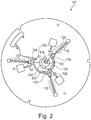
- Figs. 2-7 illustrate the distribution of a biological sample into three metering chambers.
- the cartridge 100 illustrated in Figs. 2-7 is identical to the cartridge 100 in Fig. 1 except with the addition of sample bypass channels 200 that connect the sample inlet 122 to the sample outlet 124 of the second metering chamber 118 and the last metering chamber 120.
- the addition of the sample bypass channel 200 has been shown to be effective in preserving the composition of the biological sample 108 when it is distributed to the filled metering chambers 116, 118, 120 when the sample holding chamber 106 is overfilled.
- Fig. 2 the biological sample 108 has been placed into the sample holding chamber 106 via the cartridge inlet 104.
- the cartridge 100 has not yet been rotated about the rotational axis 102.
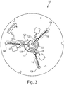
- Fig. 3 shows the cartridge 100 shortly after the cartridge 100 has begun to rotate about the rotational axis 102.
- the centrifugal force forces the biological sample 108 along the furthest edge 112.
- the three metering chambers 116, 118, 120 begin to be filled via the connecting tubes 128.
- Fig. 4 shows the cartridge 100 after it has been rotated a longer time than is shown in Fig. 3 .
- the amount of the biological sample 108 in the sample holding chamber 106 has been depleted.
- the amount of the biological sample 108 has decreased to the point that the last metering chamber 120 is no longer being filled with the biological sample 108 by the connecting tube 128.
- the first metering chamber 116 and the second metering chamber 118 are however still being filled.
- Fig. 5 shows the disc 108 after it has been rotating longer than is shown in Fig. 4 .
- the biological sample 108 has almost completely left the sample holding chamber 106.
- the second metering chamber 118 and the last metering chamber 120 are no longer being filled by the connecting tubes 128.
- the first metering chamber 116 however at this point has been completely filled.
- Biological sample 108 is now flowing out of the sample outlet 124 and through the first sample distribution channel 132 to the sample inlet 122 of the second metering chamber 118.
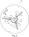
- Fig. 6 shows the cartridge 100 after it has been rotating a longer time than is shown in Fig. 5 .
- the cartridge 100 is shown at the point when all three metering chambers 116, 118, 120 have been filled.
- Some biological sample 108 can be shown as travelling through the sample distribution channels 132. After the second metering chamber 118 was filled biological sample began to flow from the sample outlet 124 of the second metering chamber 118 to the sample inlet 122 of the last metering chamber 120.
- Fig. 7 shows the cartridge 100 after it has been rotated a longer time than is shown in Fig. 6 .
- the cartridge is continued to rotate until excess biological sample 108 is transported to the waste reservoir 136.
- Fig. 8 shows a front view and Fig. 9 shows a back view of a cartridge 100 that is similar to that shown in Figs. 2-7 .
- the first, second and last metering chambers 116, 118 and 120 are chambers for separating plasma from whole blood.
- there is a microfluidic structure comprising two reagent chambers. The two reagent chambers may be used for combining one or more reagents with blood plasma that exits through the metered output 126.
- the microfluidic structure 800 is connected to a measurement structure 804.
- the measurement structure comprises a chromatographic membrane 806 which is in contact with a waste fleece 808.
- FIG. 9 shows a detection window 810 which enables a spectrographic instrument to take a measurement on the chromatographic membrane 806.
- the back side of the cartridge also shows a number of blisters or reservoirs 812 filled with washing buffer.
- the front of the cartridge shown in Fig. 8 shows a number of aliquoting structures 814 for dispensing the washing buffer multiple times for washing or cleaning the chromatographic membrane 806.
- the aliquoting structures 814 are similar in function to the structures for dispensing multiple aliquotations of a fluid that are illustrated in international patent application WO 2015/185763 .
- Fig. 10 shows an example of an automatic analyzer 1000.
- the automatic analyzer 1000 is adapted for receiving a cartridge 100.
- There is a cartridge spinner 1002 which is operable for rotating the cartridge 100 about the rotational axis 102.
- the cartridge spinner 1002 has a motor 1004 attached to a gripper 1006 which attaches to a portion of the cartridge 1008.
- the cartridge 100 is shown further as having a measurement or transparent structure 1010.
- the cartridge 300 can be rotated such that the measurement structure 1010 goes in front of a measurement system 1012 which can perform for example an optical measurement on the processed biological sample.
- the cartridge spinner 1002, and the measurement system 1012 are shown as all being connected to a hardware interface 1016 of a controller 1014.
- the controller 1014 contains a processor 1018 in communication with the hardware interface 1016, electronic storage 1020, electronic memory 1022, and a network interface 1024.
- the electronic memory 1030 has a machine executable instructions which enables the processor 1018 to control the operation and function of the automatic analyzer 1000.
- the electronic storage 1020 is shown as containing a measurement 1032 that was acquired when instructions 1030 were executed by the processor 1018.
- the network interface 1024 enables the processor 1018 to send the measurement 1032 via network interface 1026 to a laboratory information system 1028.
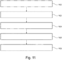
- Fig. 11 shows a flowchart which illustrates a method of operating the automatic analyzer 1000 of Fig. 10 .
- the cartridge spinner 1002 is controlled to rotate the cartridge 100 about the rotational axis to transport a portion of a biological sample from the sample holding chamber to each of the two or more metering chambers.
- Rotation of the cartridge causes simultaneous transport of a first part of the portion of the biological sample to each of the two or more metering chambers via the connecting tube for each of the two or more metering chambers.
- Rotation of the cartridge causes transport of the second part of the portion of the biological sample to each of the two or more metering chambers in serial via the at least one blood distribution channel.
- step 1102 the cartridge spinner 1002 is further controlled to control the rotation of the cartridge 100 about the rotational axis to transport a metered sample from each of the two or more metering chambers to the microfluidic structure.
- step 1104 the cartridge spinner 1002 is controlled to rotate the cartridge about the rotational axis to process the metered sample into the processed sample.
- step 1106 the cartridge spinner 1002 is controlled to rotate the cartridge to transfer the processed sample from the microfluidic structure of each of the two or more metering chambers to its measurement structure 804.
- step 1108 the measurement system 1012 is controlled to measure the amount of at least two analytes using the measurement structure 804 of each of the two or more metering chambers.
Abstract
Description
- The invention relates to analytical test devices for biological samples, in particular to the design and use of rotatable cartridges for performing a measurement of a biological sample.
- Two classes of analysis systems are known in the field of medical analysis: wet analysis systems, and dry-chemical analysis systems. Wet analysis systems, which essentially operate using "wet reagents" (liquid reagents), perform an analysis via a number of required step such as, for example, providing a sample and a reagent into a reagent vessel, mixing the sample and reagent together in the reagent vessel, and measuring and analyzing the mixture for a measurement variable characteristic to provide a desired analytical result (analysis result). Such steps are often performed using technically complex, large, line-operated analysis instruments, which allow manifold movements of participating elements. This class of analysis system is typically used in large medical-analytic laboratories.
- On the other hand, dry-chemical analysis systems operate using "dry reagents" which are typically integrated in a test element and implemented as a "test strip", for example. When these dry-chemical analysis systems are used, the liquid sample dissolves the reagents in the test element, and the reaction of sample and dissolved reagent results in a change of a measurement variable, which can be measured on the test element itself. Above all, optically analyzable (in particular colorimetric) analysis systems are typical in this class, in which the measurement variable is a color change or other optically measurable variable. Electrochemical systems are also typical in this class, in which an electrical measurement variable characteristic for the analysis, in particular an electrical current upon application of a defined voltage, can be measured in a measuring zone of the test element using electrodes provided in the measuring zone.
- The analysis instruments of the dry-chemical analysis systems are usually compact, and some of them are portable and battery-operated. The systems are used for decentralized analysis, for example, at resident physicians, on the wards of the hospitals, and in so-called "home monitoring" during the monitoring of medical-analytic parameters by the patient himself (in particular blood glucose analysis by diabetics or coagulation status by warfarin patients).
- In wet analysis systems, the high-performance analysis instruments allow the performance of more complex multistep reaction sequences ("test protocols"). For example, immunochemical analyses often require a multistep reaction sequence, in which a "bound/free separation" (hereafter "b/f separation"), i.e., a separation of a bound phase and a free phase, is necessary. According to one test protocol, for example, the probe can first be transported through a porous solid matrix, which contains a specific binding reagent for the analyte. A marking reagent can subsequently be caused to flow through the porous matrix, to mark the bound analyte and allow its detection. To achieve precise analysis, a washing step must be performed, in which unbound marking reagent is completely removed. Numerous test protocols are known for determining manifold analytes, which differ in manifold ways, but which share the feature that they require complex handling having multiple reaction steps, in particular also a b/f separation possibly being necessary.
- Test strips and similar analysis elements normally do not allow controlled multistep reaction sequences. Test elements similar to test strips are known, which allow further functions, such as the separation of red blood cells from whole blood, in addition to supplying reagents in dried form. However, they normally do not allow precise control of the time sequence of individual reaction steps. Wet-chemical laboratory systems offer these capabilities, but are too large, too costly, and too complex to handle for many applications.
- To close these gaps, analysis systems have been suggested which operate using test elements which are implemented in such a manner that at least one externally controlled (i.e., using an element outside the test element itself) liquid transport step occurs therein ("controllable test elements"). The external control can be based on the application of pressure differences (overpressure or low-pressure) or on the change of force actions (e.g., change of the action direction of gravity by attitude change of the test element or by acceleration forces). The external control is especially frequently performed by centrifugal forces, which act on a rotating test element as a function of the velocity of the rotation.
- Analysis systems having controllable test elements are known and typically have a housing, which comprises a dimensionally-stable plastic material, and a sample analysis channel enclosed by the housing, which often comprises a sequence of multiple channel sections and chambers expanded in comparison to the channel sections lying between them. The structure of the sample analysis channel having its channel sections and chambers is defined by profiling of the plastic parts. This profiling is able to be generated by injection molding techniques or hot stamping. Microstructures, which are generated by lithography methods, increasingly being used more recently, however.
- Analysis systems having controllable test elements allow the miniaturization of tests which have only been able to be performed using large laboratory systems. In addition, they allow the parallelization of procedures by repeated application of identical structures for the parallel processing of similar analyses from one sample and/or identical analyses from different samples. It is a further advantage that the test elements can typically be produced using established production methods and that they can also be measured and analyzed using known analysis methods. Known methods and products can also be employed in the chemical and biochemical components of such test elements.
- In spite of these advantages, there is a further need for improvement. In particular, analysis systems which operate using controllable test elements are still too large. The most compact dimensions possible are of great practical significance for many intended applications.
- United States patent
US 8,114,351 B2 discloses an analysis system for the analysis of a body fluid sample for an analyte. The analysis system provides a test element and an analysis instrument having a dosing station and a measurement station. The test element has a housing an (at least) one sample analysis channel enclosed by the housing. The test element is rotatable around an axis of rotation which extends through the test element. - United States patent
8,470,588 B2 discloses a test element and a method for detecting an analyte. The test element is essentially disk shaped and flat, and can be rotated about a preferably central axis which is perpendicular to the plane of the disk shaped test element. - Kim, Tae-Hyeong, et al. "Flow-enhanced electrochemical immunosensors on centrifugal microfluidic platforms." Lab on a Chip 13.18 (2013): 3747-3754, doi:10.1039/c3Ic50374g, (hereafter "Kim et. al.") discloses a fully integrated centrifugal microfluidic device with features for target antigen capture from biological samples, via a bead-based enzyme-linked immune-sorbent assay, and flow-enhanced electrochemical detection. This is integrated into a Centrifugal microfluidic discs, also known as "lab-on-a-disc" or microfluidic CDs.
- Martinez-Duarte, Rodrigo, et al. "The integration of 3D carbon-electrode dielectrophoresis on a CD-like centrifugal microfluidic platform." Lab on a Chip 10.8 (2010): 1030-1043, doi:10.1039/B925456K, (hereafter "Martinez-Duarte et. al.") discloses a dielectrophoresis (DEP)-assisted filter with a compact disk (CD)-based centrifugal platform. 3D carbon electrodes are fabricated using the C-MEMS technique and are used to implement a DEP-enabled active filter to trap particles of interest.
- The invention provides for a method, a cartridge and a automatic analyzer in the independent claims. Embodiments are given in the dependent claims.
- The use of rotational cartridges with fluidic structures to perform tests on biological samples can provide for cartridge and automatic analyzer systems that can be distributed to such places as clinics or doctors' offices. They may provide a very convenient and accurate way of providing diagnostic results inexpensively and quickly. A difficulty is that often times doctors or other caregivers may be interested in obtaining multiple test results. This can mean that a comparatively large volume of a biological sample needs to be obtained in order to have enough of the biological sample to place in to multiple cartridges.
- It is not at all easy to divide a biological sample into multiple portions to have independent tests on the same cartridge. A major issue is that many biological samples have multiple components. For example a whole blood sample may comprise blood plasma, erythrocytes, and lipids. The act of dividing a whole blood sample into multiple portions for different diagnostic tests can have the effect of changing the ratio of plasma, erythrocytes, and lipids within the multiple portions. This can result in skewed or inaccurate test results.
- Empirical tests of rotational cartridges showed that feeding multiple metering chambers simultaneously with whole blood results in in accurate test results. Other test structures were also tried. Experiments were also performed where a series of metering chambers were filled sequentially. As the disk was rotated the whole blood was first forced into a first metering chamber. Sample distribution channels were used to connect the metering chambers sequentially or serially. This then caused the metering chambers to fill one after the other. These test cartridges also provided skewed or inaccurate test results. The relative ratio of the blood plasma, the erythrocytes and lipids was wrong. The multiple tests were inconsistent with each other.
- Embodiments of the invention may provide for a means of dividing a biological sample into multiple portions while maintaining its original composition closely enough so that accurate tests can be performed on each of the samples.
- Example cartridges do this by providing two separate pathways for filling the metering chambers with the biological sample. Embodiments have a holding chamber which initially stores the biological sample. Individual metering chambers are distributed about or around the holding chamber. There is a connecting tube for each of the metering chambers that is connected between the holding chamber and an inlet of the respective metering chamber. The metering chambers each have a sample inlet and and outlet. The metering chambers are connected by a series of sample distribution channels. The sample distribution channels are connected from the outlet of one metering chamber to the inlet of an adjacent metering chamber. The sample distribution channels cause the metering chambers to fill serially or one after the other.
- The connecting tubes provide a parallel or simultaneous filling pathway for the metering chambers, and the distribution channels form a sequential filling pathway for the metering chamber. When the cartridge is rotated about its rotational axis the biological sample is then forced through the connecting tubes and each of the metering chambers begins to fill. As metering chambers begin to be filled completely the excess is routed through a distribution channel to a neighboring or adjacent metering chamber. The effect of using both means of filling the metering chambers is that biological sample in the metering chambers more closely resembles the composition of the biological sample that was originally placed in the sample holding chamber.
- The above described structure was tested with whole blood. The effect is also valid for other biological samples such as semen, a stool sample mixed with fluid, or other fluids which have multiple components. It is also beneficial to use with biological samples that are not normally considered to have multiple components, because a biological sample can be contaminated. For example urine could be contaminated with cells or even calcium crystals. Use of the cartridges described herein may provide for a test structure that provides for more accurate, uniform, and robust results when the original biological sample is divided into multiple sub samples using two or more metering chambers.
- A cartridge as used here encompasses also any test element for processing the biological sample into a processed biological sample. The cartridge may include structures or components which enable a measurement to be performed on the biological sample. A cartridge is a test element as is defined and explained in
US patents 8,114,351 B2 and8,470,588 B2 . A cartridge as used herein may also be referred to as a Centrifugal microfluidic disc, also known as "lab-on-a-disc" or a microfluidic CD. - It is understood that references to biological samples and products below and in the claims may be modified such that they refer to blood samples and/or blood products and/or whole blood.
- A biological sample as used herein encompasses a chemical product derived, copied, replicated, or reproduced from a sample taken from an organism.
- In one aspect the invention provides for a method of determining an amount of at least two analytes in a biological sample using a cartridge. The biological sample comprises a fluid. The cartridge is operable for being spun around a rotational axis.
- The invention may also provides for a method of determining an amount of one analyte at least two times (to increase the precision of the analysis) in a biological sample using a cartridge.
- The cartridge comprises a cartridge inlet for receiving the biological sample. The cartridge further comprises a sample holding chamber connected to the cartridge inlet. The cartridge further comprises two or more metering chambers for receiving a predetermined volume of the biological sample. Each of the two or more metering chambers comprises a sample inlet. Each of the two or more metering chambers comprises a sample outlet. Each of the two or more metering chambers comprises an outlet for a metered sample volume. The metered sample volume is a portion of the predetermined volume of the biological sample that goes into each of the metering chambers.
- The cartridge further comprises a connecting tube for each of the two or more metering chambers that fluidically connect the sample inlet with the sample holding chamber. The cartridge further comprises at least one sample distribution channel. Each of the at least one sample distribution channel is connected between the sample outlet of a first selected metering chamber with the sample inlet of a second selected metering chamber. The two or more metering chambers comprise the first selected metering chamber. The two or more metering chambers comprise the second selected metering chamber. The second selected metering chamber is adjacent to the first selected metering chamber.
- The connecting tube connects the individual metering chambers directly with the sample holding chamber. The sample distribution channels are configured to serially connect the metering chambers. This provides two distinct routes for the biological sample to flow into each of the two or more metering chambers.
- The cartridge further comprises a microfluidic structure for each of the two or more metering chambers. The microfluidic structure is connected to the sample outlet. The microfluidic structure is configured for processing the metering sample volume into a processed sample. The cartridge further comprises a measurement structure for each of the two or more metering chambers for enabling measurement of the processed sample to determine a concentration of the analyte in the processed sample. The concentration of the analyte is directly related to the concentration of the analyte in the biological sample. The measurement structure is fluidically connected to the microfluidic structure.
- The measurement structure may take different forms in different examples. For example in one example the measurement structure may be a chromatographic membrane with antibodies that attach to markers in the processed sample. Fluorescent markers may then be used to perform the measurement of the amount of the analyte. In other examples, the processed sample may be transported to an optically transparent container or region which may then be subjected to spectrographic measurements.
- The method comprises placing the biological sample into the cartridge inlet to at least partially fill the sample holding chamber. The method further comprises rotating the cartridge about the rotational axis to transport a portion of the sample from the sample holding chamber to each of the two or more metering chambers. Rotation of the cartridge causes simultaneous transport of a first part of the portion of the sample to each of the two or more metering chambers via the connecting tube for each of the two or more metering chambers. Rotation of the cartridge further causes transport of a second part of the portion of the sample to each of the two or more metering chambers in serial via the at least one sample distribution channel. The simultaneous transfer of fluid via two different routes to the two or more metering chambers may be beneficial because the composition of the predetermined volume of the biological sample may have a composition or makeup that is closer to the biological sample if only one of the two routes is used. For example multi-component biological samples such as whole blood contain essentially a solid such as whole blood cells, blood plasma and also lipids. The use of the multiple ways of filling the two or more metering chambers may provide for better results. The method further comprises controlling the rotation of the cartridge about the rotational axis to transport the metered sample from each of the two or more metering chambers to the microfluidic structure. The method further comprises controlling the rotation of the cartridge about the rotational axis to process the sample into the processed sample. The method further comprises controlling the rotation of the cartridge to transfer the processed sample from the microfluidic structure of each of the two or more metering chambers to the measurement structure. The method further comprises measuring the amount of the at least two analytes using the measurement structure of each of the two or more metering chambers and a measurement system. The measurement may include, but is not limited to: a photometric transmission measurement, a measurement of the scattering of light, a chemiluminescence, a fluorescence, an electrochemical and electrochemiluminescense (ECL) measurement.
- This embodiment may be beneficial because providing multiple routes for the biological sample to the two or more metering chambers may provide more accurate measurement of the amount of the at least two analytes.
- In another embodiment the cartridge inlet is located closer to the rotational axis than the sample holding chamber. The sample holding chamber is elongated along an elongated path. The elongated path is at least partially encircling the rotational axis. The sample holding chamber has a furthest edge from the rotational axis. The distance from the furthest edge to the rotational axis increases along the elongated path. The connecting tube for each of the two or more metering chambers is connected to the sample holding chamber at the furthest edge. This embodiment may be beneficial because the structure of the sample holding chamber may force blood through each of the connecting tubes into the two or more metering chambers individually.
- In another embodiment the biological sample is a multi-component fluid. A multi-component fluid as used herein encompasses a fluid that is mixed any one of the following: with a solid or sediment, a second fluid, biological cells, a colloidal suspension, an oil, a lipid, blood serum, and combinations thereof.
- In another aspect the invention provides for a cartridge for determining an amount of at least two analytes in a biological sample. The cartridge is operable for being spun around a rotational axis. The cartridge comprises a cartridge inlet for receiving the biological sample. The cartridge further comprises a sample holding chamber connected to the cartridge inlet. The cartridge further comprises two or more metering chambers for the biological sample for receiving a predetermined volume of the biological sample. Each of the two or more metering chambers comprises a sample inlet. Each of the two or more metering chambers comprises a metered outlet. The cartridge further comprises a connecting tube for each of the two or more metering chambers that fluidically connect the sample inlet with the sample holding chamber. The cartridge further comprises at least one sample distribution chamber.
- Each of the at least one sample distribution chamber is connected with the sample outlet of a first selected metering chamber with a sample inlet and a second selected metering chamber. The two or more metering chambers comprise the first selected metering chamber. The two or more metering chambers comprise the second selected metering chamber. The second selected metering chamber is adjacent to the first selected metering chamber. The cartridge further comprises a microfluidic structure for each of the two or more metering chambers. The microfluidic structure is connected to the sample outlet. The microfluidic structure is configured for processing the biological sample into a processed sample. The cartridge further comprises a measurement structure for each of the two or more metering chambers for enabling measurement of the processed sample to determine the amount of the analyte in the sample. The measurement structure is fluidically connected to the microfluidic structure.
- In another embodiment the two or more metering chambers comprise a first filled metering chamber and one or more sequentially filled metering chambers. The term first filled metering chamber is a label which is used to refer to one of the metering chambers. Each of the one or more sequentially filled metering chambers comprises a sample bypass channel that fluidically connects the sample inlet with the sample outlet. The use of the sample bypass channel may be beneficial because it may enable the cartridge to distribute the biological sample to each of the two or more metering chambers when the sample holding chamber is overfilled.
- In another embodiment the two analytes each comprise any one of the following: Troponin T, Troponin I, CKMB, NTproBNP, D-Dimer, Myoglobin, Thyroid-stimulating hormone (TSH) and Procalcitonin (PCT).
- In another embodiment the cartridge is formed from a plastic disc and a cover plate. At least a portion of the sample chamber is visible through the cover plate and/or the plastic disc. Making the portion of the sample chamber visible may be useful in aiding an operator of the cartridge in seeing when the sample chamber is properly filled.
- In another embodiment the sample holding chamber is configured for receiving the sample with a volume between 30 µl and 500 µl. The broad range may be beneficial because it is not necessary for the user of the cartridge to accurately measure the biological sample before placing it into the cartridge inlet.
- In another embodiment each of the measurement structures is a chromatographic membrane.
- In another embodiment the measurement structure comprises a waste fleece or absorbent zone.
- The chromatographic membrane may be referred to as a capillary-active zone. In one embodiment, the capillary-active zone comprises a porous, absorbent matrix. In one embodiment of the test element according to the invention, the second end of the capillary-active zone near to the axis adjoins a further absorbent material or an absorbent structure such that it can take up liquid from the capillary-active zone. The capillary-active zone and the further absorbent material typically slightly overlap for this purpose. The further material or the further absorbent structure serve on the one hand, to assist the suction action of the capillary-active zone and in particular of the porous, absorbent matrix and, on the other hand, serve as a holding zone for liquid which has already passed through the capillary-active zone. In this connection the further material can consist of the same materials or different materials than the matrix. For example, the matrix can be a membrane and the further absorbent material can be a fleece or a paper. Other combinations are of course equally possible.
- The fluidic structure may contain a reagent zone which contains a conjugate of an analyte binding partner (typically an antibody or an immunologically active antibody fragment capable of analyte binding if the analyte is an antigen or hapten, or an antigen or hapten if the analyte is an antibody) and a label which can be detected directly or indirectly by visual, optical or electrochemical means, wherein the conjugate can be dissolved by the liquid sample. Suitable labels are, for example, enzymes, fluorescent labels, chemiluminescent labels, electrochemically active groups or so-called direct labels such as metal or carbon labels or colored lattices. This zone may also referred to as the conjugate zone.
- The conjugate zone can serve also as a sample application zone or a separate sample application zone can be located on the test element. The conjugate zone can, in addition to the conjugate of analyte binding partner and label described above, also contain an additional conjugate of a second analyte binding partner (which is in turn typically an antibody or an immunologically active antibody fragment capable of analyte binding) and a tagging substance which is itself a partner in a binding pair. The tagging substance can for example be biotin, streptavidin or digoxigenin and can be used to immobilize a sandwich complex consisting of labelled conjugate, analyte and tagged conjugate in the detection and/or control zone.
- The chromatographic membrane may additionally comprise a detection zone which contains a permanently immobilized binding partner (i.e., one that cannot be detached by the liquid sample) for the analyte or for complexes containing the analyte. The immobilized binding partner is in turn typically an antibody or an immunologically active antibody fragment capable of analyte binding or an antigen or (poly)hapten. If one of the above-mentioned tagged conjugates is used which for example comprises biotin or digoxigenin together with an analyte binding partner, the immobilized binding partner can also be streptavidin or polystreptavidin and an anti-digoxigenin antibody.
- Finally, there may also be a control zone in or on the chromatographic membrane which contains a permanently immobilized binding partner for the conjugate of analyte binding partner and label for example in the form of an immobilized polyhapten which acts as an analyte analogue and is able to bind the analyte binding partner from the labeled conjugate. The control zone may additionally contain one or more permanently immobilized binding partner(s) for the analyte or for complexes containing the analyte. The latter binding partners can be selected from the same compounds which were described above in connection with the immobilized binding partners of the detection zone. These immobilized binding partners in the detection zone and in the control zone are typically identical. They may, however, also be different for example in that a binding partner for a biotin-tagged conjugate (hence, e.g., polystreptavidin) is immobilized in the detection zone and an anti-analyte antibody is immobilized in the control zone in addition to the polyhapten. In the latter case the anti-analyte antibody that is additionally immobilized in the control zone should be directed against (another) independent epitope and thus one that is not recognized by the conjugate antibodies (biotin-tagged conjugate and labelled conjugate).
- In another embodiment, the absorbent structure is a waste fleece.
- In another embodiment, the chromatographic membrane can contain one or more zones containing immobilized reagents.
- Specific binding reagents for example specific binding partners such as antigens, antibodies, (poly) haptens, streptavidin, biotin, polystreptavidin, ligands, receptors, nucleic acid strands (capture probes) are typically immobilized in the capillary-active zone and in particular in the porous, absorbent matrix. They are used to specifically capture the analyte or species derived from the analyte or related to the analyte from the sample flowing through the capillary-active zone. These binding partners can be present immobilized in or on the material of the capillary-active zone in the form of lines, points, patterns or they can be indirectly bound to the capillary-active zone e.g., by means of so-called beads. Thus, for example, in the case of immunoassays one antibody against the analyte can be present immobilized on the surface of the capillary-active zone or in the porous, absorbent matrix which then captures the analyte (in this case an antigen or hapten) from the sample and also immobilizes it in the capillary-active zone such as, e.g., the absorbent matrix. In this case the analyte can be made detectable for example by means of a label that can be detected visually, optically or fluorescence-optically by further reactions, for example by additionally contacting it with a labelled bindable partner.
- In another embodiment, the fluidic structure contains a first specific binding partner of the analyte with a detectable label and a second specific binding partner with a capture label. These both form a binding complex with the analyte. This may consist of a first specific binding partner, a second specific binding partner and an analyte. This may additionally provide for a measurement structure within the immobilized binding partner specific to the capture label of the second specific binding partner.
- In another embodiment, the detection is fluorescence-based.
- In another embodiment, the label is particle-based fluorescent label.
- In another embodiment, the chromatographic membrane contains an optical calibration zone. The optical calibration zone may for example be a region on the measurement structure which contains a defined amount of the immobilized label and provides a means for checking if the optics of the instrument is functioning properly and if not, to calibrate it adequately. In other embodiments, the optical calibration zone is located at different locations on the test element.
- In another embodiment, the measurement structure contains a reagent and flow control zone. This may provide for a means of checking if the cartridge is functioning properly in terms of reagents and immunochromatography. There may be for example two different control zones, a reagent/flow-control and an optical calibration zone as instrument control zone for correcting the intensity of the radiation or excitation source when an optical measurement is made.
- In another embodiment, the cartridge is disk-shaped or at least partially disk-shaped.
- In another embodiment, the cartridge may have an outer edge which fits within a circle drawn around the rotational axis.
- In another embodiment, the cartridge has an outer edge. The outer edge may have a portion or portions that are circularly symmetric around the rotational axis.
- In another embodiment the two or more metering chambers are any one of the following: three metering chambers, four metering chambers, and five metering chambers.
- In another embodiment the two or more metering chambers comprises a last filled metering chamber. The term last filled metering chamber is a label for a particular metering chamber. The cartridge further comprises a waste reservoir connected to the sample outlet of the metering chamber. When the two or more metering chambers are filled sequentially the last filled metering chamber is the one that is furthest on the chain of the sample distribution channels.
- In another embodiment the cartridge inlet is located closer to the rotational axis than the sample holding chamber. The sample holding chamber is elongated along an elongated path. The elongated path is at least partially encircling the rotational axis. The sample holding chamber has a furthest edge from the rotational axis. The distance from the furthest edge to the rotational axis increases along the elongated path. The connecting tube for each of the two or more metering chambers is connected to the sample holding chamber at the furthest edge.
- In another embodiment the connecting tube of each of the two or more metering chambers further connects to one of the at least one sample distribution channel adjacent to the sample inlet. This may be beneficial because it provides a common place for the biological sample to enter the metering chamber.
- In another embodiment the connecting tube of each of the two or more metering chambers comprises a capillary stop. The use of the capillary stop may be beneficial because the fluid in the sample holding chamber does not flow or move into the two or more metering chambers until a rotation of the cartridge about the rotational axis begins. This may be beneficial in controlling the flow of the biological sample into the two or more metering chambers.
- In another embodiment the biological fluid is any one of the following: whole blood, urine, semen, saliva, a stool sample mixed with a liquid, blood plasma, blood serum and interstitial fluid.
- In another embodiment the measurement structure comprises two or more electrodes and/or an optical measurement structure. The measurement system comprises a system for making an electrical measurement. The measurement system comprises a system for making optical measurements.
- In some embodiments the optical measurement structure may be a transparent structure or an optically transparent structure. The measurement system comprises an optical measurement system.
- In some examples optically transparent may include near infrared and near ultraviolet. In other examples optically transparent may exclude the near infrared or near ultraviolet.
- Some examples may have both the measurement structure with the transparent structure and also the electrodes for more complicated tests. For example the measurement structure may be a structure for making electrochemiluminescence measurements where electrodes cause an optical excitation in a sample.
- In other examples the measurement structure comprises two or more electrodes for making an electrical measurement or ECL measurement of the processed biological sample. For example the measurement structures of Martinez-Duarte et. al. or Kim et. al. may be incorporated into a cartridge.
- Examples may also only have electrode. For example in an electrochemical detection structure an electrode may be used to measure a current caused by the result of a enzymatic reaction.
- In another aspect, the automatic analyzer further comprises a cartridge spinner for controlling the rotation of the cartridge about the rotational axis. The automatic analyzer further comprises a measurement system for measuring the amount of the at least two analytes using the measurement structure of each of the two or more metering chambers.
- The automatic analyzer further comprises a memory for storing machine-executable instructions and a processor for controlling the automatic analyzer. Execution of the machine-executable instructions further cause the processor to control the cartridge spinner to rotate the cartridge about the rotational axis to transport a portion of a biological sample from the sample holding chamber to each of the two or more metering chambers. Rotation of the cartridge causes simultaneous transport of a first part of the portion of the biological sample to each of the two or more metering chambers via the connecting tubes for each of the two or more metering chambers. Rotation of the cartridge causes transport of a second part of the portion of the biological sample to each of the two or more metering chambers in serial via the at least one blood distribution channel.
- Execution of the machine-executable instructions further causes the processor to control the cartridge spinner to control the rotation of the cartridge about the rotational axis to transport a metered sample from each of the two or more metering chambers to the microfluidic structure. Execution of the machine-executable instructions further cause the processor to control the cartridge spinner to control the rotation of the cartridge about the rotational axis to process the metered sample into a processed sample. Execution of the machine-executable instructions further cause the processor to control the cartridge spinner to control the rotation of the cartridge to transfer the processed sample from the microfluidic structure of each of the two or more metering chambers to the measurement structure. Execution of the machine-executable instructions further cause the processor to measure the amount of at least two analytes using the measurement structure of each of the two or more metering chambers and a measurement system.
- In another embodiment the biological sample is a whole blood sample. The two or more metering chambers are two or more plasma separation chambers. The plasma separation chamber may also be referred to as a blood separation chamber. The United States Patent
US 2009/0191643 A1 illustrates a microfluidic structure in a rotational disc that is able to separate serum or plasma from the blood cell fraction (mainly the erythrocytes) of a whole blood sample. - Execution of the machine-executable instructions further cause the processor to control the cartridge spinner to control the rotation of the cartridge about the rotational axis to separate blood plasma from the portion of the whole blood sample in each of the two or more plasma separation chambers by centrifugation.
- It is understood that one or more of the aforementioned embodiments of the invention may be combined as long as the combined embodiments are not mutually exclusive.
- In the following embodiments of the invention are explained in greater detail, by way of example only, making reference to the drawings in which:
- Fig. 1
- illustrates an example of a cartridge;
- Fig. 2
- illustrates a further example of a cartridge;
- Fig. 3
- shows a further view of the cartridge of
Fig. 2 ; - Fig. 4
- shows a further view of the cartridge of
Fig. 2 ; - Fig. 5
- shows a further view of the cartridge of
Fig. 2 ; - Fig. 6
- shows a further view of the cartridge of
Fig. 2 ; - Fig. 7
- shows a further view of the cartridge of
Fig. 2 ; - Fig. 8
- illustrates a further example of a cartridge;
- Fig. 9
- shows a further view of the cartridge of
Fig. 8 ; - Fig. 10
- illustrates an example of an automatic analyzer; and
- Fig. 11
- shows a flow chart which illustrates a method of using the automatic analyzer of
Fig. 10 . - Like numbered elements in these figures are either equivalent elements or perform the same function. Elements which have been discussed previously will not necessarily be discussed in later figures if the function is equivalent.
-
Fig. 1 shows an example of a cartridge. Thecartridge 100 has arotational axis 102. The cartridge also comprises acartridge inlet 104. In this example thecartridge inlet 104 is located where therotational axis 102 is. However, thecartridge inlet 104 could also be off of therotational axis 102. Thecartridge inlet 104 is connected to asample holding chamber 106. In this example thesample holding chamber 106 follows anelongated path 110. The elongated path partially wraps around therotational axis 102. Thesample holding chamber 106 has afurthest edge 112 that is the edge furthest from therotational axis 102. - The
sample holding chamber 106 inFig. 1 can be seen as containing abiological sample 108 that has been placed into thesample holding chamber 106. Within various structures of thecartridge 100 there can be seen a number ofevents 114. Thecartridge 100 further comprises afirst metering chamber 116, asecond metering chamber 118, and alast metering chamber 120. Eachmetering chamber sample inlet 122, asample outlet 124, and ametered outlet 126. There is a connectingtube 128 for each of themetering chambers sample inlet 122 to thefurthest edge 112 of thesample holding chamber 106. Fluid can travel directly from thesample holding chamber 106 to thesample inlets 122. - In
Fig. 1 there are also twosample distribution channels 132 that are shown. Thesample distribution channels 132 are used to also sequentially fill themetering chambers sample distribution channels 132 connects thesample outlet 124 of thefirst metering chamber 116 to thesample inlet 122 of thesecond metering chamber 118. There is a secondsample distribution channel 132 connected to thesample outlet 124 of thesecond metering chamber 118 and connected to thesample inlet 122 of thelast metering chamber 120. The combination of the connectingtubes 128 and thesample distribution channels 132 cause themetering chambers - For example if the
biological sample 108 contains a solid such as red blood cells, as it spins it may cause the red blood cells to concentrate in thefirst metering chamber 116. Also using as an example, whole blood also contains fatty components such as lipids. When performing multiple tasks using a single sample it is beneficial if the original biological sample has a composition in themetering chambers biological sample 108. The use of both the connectingtubes 128 to fill in parallel and thesample distribution channels 132 to fill in serial have been shown experimentally to provide samples in themetering chambers biological sample 108 more closely than if the filling of themetering chambers - Each of the
metering chambers metered output 126 that is connected to a fluidic element. Thefluidic element 134 depicted inFig. 1 was a test element used to simulate a microfluidic structure and a measurement structure on a test disc. Thefluidic structure 134 may be used to collect the metered biological sample. Thefluidic elements 134 may be easily replaced with other structures such as a microfluidic structure for processing the metered sample into a processed sample and also a measurement structure. Such structures are shown in some later Figs. - The
cartridge 100 is shown as optionally containing awaste reservoir 136 which is connected to thesample outlet 124 of thelast metering chamber 120. -
Figs. 2-7 illustrate the distribution of a biological sample into three metering chambers. Thecartridge 100 illustrated inFigs. 2-7 is identical to thecartridge 100 inFig. 1 except with the addition ofsample bypass channels 200 that connect thesample inlet 122 to thesample outlet 124 of thesecond metering chamber 118 and thelast metering chamber 120. In experiments the addition of thesample bypass channel 200 has been shown to be effective in preserving the composition of thebiological sample 108 when it is distributed to the filledmetering chambers sample holding chamber 106 is overfilled. - In
Fig. 2 thebiological sample 108 has been placed into thesample holding chamber 106 via thecartridge inlet 104. InFig. 2 thecartridge 100 has not yet been rotated about therotational axis 102. -
Fig. 3 shows thecartridge 100 shortly after thecartridge 100 has begun to rotate about therotational axis 102. The centrifugal force forces thebiological sample 108 along thefurthest edge 112. The threemetering chambers tubes 128. -
Fig. 4 shows thecartridge 100 after it has been rotated a longer time than is shown inFig. 3 . The amount of thebiological sample 108 in thesample holding chamber 106 has been depleted. The amount of thebiological sample 108 has decreased to the point that thelast metering chamber 120 is no longer being filled with thebiological sample 108 by the connectingtube 128. Thefirst metering chamber 116 and thesecond metering chamber 118 are however still being filled. -
Fig. 5 shows thedisc 108 after it has been rotating longer than is shown inFig. 4 . InFig. 5 thebiological sample 108 has almost completely left thesample holding chamber 106. Thesecond metering chamber 118 and thelast metering chamber 120 are no longer being filled by the connectingtubes 128. Thefirst metering chamber 116 however at this point has been completely filled.Biological sample 108 is now flowing out of thesample outlet 124 and through the firstsample distribution channel 132 to thesample inlet 122 of thesecond metering chamber 118. -
Fig. 6 shows thecartridge 100 after it has been rotating a longer time than is shown inFig. 5 . InFig. 6 thecartridge 100 is shown at the point when all threemetering chambers biological sample 108 can be shown as travelling through thesample distribution channels 132. After thesecond metering chamber 118 was filled biological sample began to flow from thesample outlet 124 of thesecond metering chamber 118 to thesample inlet 122 of thelast metering chamber 120. -
Fig. 7 shows thecartridge 100 after it has been rotated a longer time than is shown inFig. 6 . The cartridge is continued to rotate until excessbiological sample 108 is transported to thewaste reservoir 136. -
Fig. 8 shows a front view andFig. 9 shows a back view of acartridge 100 that is similar to that shown inFigs. 2-7 . In this example the first, second andlast metering chambers output 126. Themicrofluidic structure 800 is connected to ameasurement structure 804. The measurement structure comprises achromatographic membrane 806 which is in contact with awaste fleece 808. The back side of the cartridge depicted inFig. 9 shows adetection window 810 which enables a spectrographic instrument to take a measurement on thechromatographic membrane 806. The back side of the cartridge also shows a number of blisters orreservoirs 812 filled with washing buffer. The front of the cartridge shown inFig. 8 shows a number ofaliquoting structures 814 for dispensing the washing buffer multiple times for washing or cleaning thechromatographic membrane 806. The aliquotingstructures 814 are similar in function to the structures for dispensing multiple aliquotations of a fluid that are illustrated in international patent applicationWO 2015/185763 . -
Fig. 10 shows an example of anautomatic analyzer 1000. Theautomatic analyzer 1000 is adapted for receiving acartridge 100. There is a cartridge spinner 1002 which is operable for rotating thecartridge 100 about therotational axis 102. The cartridge spinner 1002 has a motor 1004 attached to agripper 1006 which attaches to a portion of thecartridge 1008. Thecartridge 100 is shown further as having a measurement or transparent structure 1010. The cartridge 300 can be rotated such that the measurement structure 1010 goes in front of ameasurement system 1012 which can perform for example an optical measurement on the processed biological sample. - The cartridge spinner 1002, and the
measurement system 1012 are shown as all being connected to ahardware interface 1016 of acontroller 1014. Thecontroller 1014 contains aprocessor 1018 in communication with thehardware interface 1016,electronic storage 1020,electronic memory 1022, and anetwork interface 1024. Theelectronic memory 1030 has a machine executable instructions which enables theprocessor 1018 to control the operation and function of theautomatic analyzer 1000. Theelectronic storage 1020 is shown as containing ameasurement 1032 that was acquired wheninstructions 1030 were executed by theprocessor 1018. Thenetwork interface 1024 enables theprocessor 1018 to send themeasurement 1032 vianetwork interface 1026 to alaboratory information system 1028. -
Fig. 11 shows a flowchart which illustrates a method of operating theautomatic analyzer 1000 ofFig. 10 . First instep 1100 the cartridge spinner 1002 is controlled to rotate thecartridge 100 about the rotational axis to transport a portion of a biological sample from the sample holding chamber to each of the two or more metering chambers. Rotation of the cartridge causes simultaneous transport of a first part of the portion of the biological sample to each of the two or more metering chambers via the connecting tube for each of the two or more metering chambers. Rotation of the cartridge causes transport of the second part of the portion of the biological sample to each of the two or more metering chambers in serial via the at least one blood distribution channel. Next instep 1102 the cartridge spinner 1002 is further controlled to control the rotation of thecartridge 100 about the rotational axis to transport a metered sample from each of the two or more metering chambers to the microfluidic structure. Next instep 1104 the cartridge spinner 1002 is controlled to rotate the cartridge about the rotational axis to process the metered sample into the processed sample. Next instep 1106 the cartridge spinner 1002 is controlled to rotate the cartridge to transfer the processed sample from the microfluidic structure of each of the two or more metering chambers to itsmeasurement structure 804. Finally instep 1108 themeasurement system 1012 is controlled to measure the amount of at least two analytes using themeasurement structure 804 of each of the two or more metering chambers. -
- 100
- cartridge
- 102
- rotational axis
- 104
- cartridge inlet
- 106
- sample holding chamber
- 108
- biological sample
- 110
- elongated path
- 112
- furthest edge
- 114
- vent
- 116
- first metering camber
- 118
- second metering chamber
- 120
- last metering chamber
- 122
- sample inlet
- 124
- sample outlet
- 126
- metered outlet
- 128
- connecting tube
- 130
- capillary stop
- 132
- sample distribution channel
- 134
- fluidic element
- 136
- waste reservoir
- 200
- sample bypass channel
- 800
- microfluidic structure
- 802
- reagent chamber
- 804
- measurement structure
- 806
- chromatographic membrane
- 808
- waste fleece
- 810
- detection window
- 812
- blister with washing buffer
- 814
- aliquoting structure
- 1000
- automatic analyzer
- 1002
- cartridge spinner
- 1004
- motor
- 1006
- gripper
- 1008
- portion of cartridge
- 1010
- measurement structure
- 1012
- measurement system
- 1014
- controller
- 1016
- hardware interface
- 1018
- processor
- 1020
- electronic storage
- 1022
- electronic memory
- 1024
- network interface
- 1026
- network connection
- 1028
- laboratory information system
- 1030
- executable instructions
- 1032
- measurement
Claims (15)
- A method of determining an amount of at least two analytes in a biological sample (108) using a cartridge (100), wherein the biological sample comprises a fluid, wherein the cartridge is operable for being spun around a rotational axis (102), wherein the cartridge comprises:- a cartridge inlet (104) for receiving the biological sample;- a sample holding chamber (106) fluidically connected to the cartridge inlet;- two or more metering chambers (116, 118, 120) for receiving a predetermined volume of the biological sample, wherein each of the two or more metering chambers comprises a sample inlet (122), wherein each of the two or more metering chambers comprises a sample outlet (124), wherein each of the two or more metering chambers comprises a metered outlet (126) for dispensing a predetermined volume;- a connecting tube (128) for each of the two or more metering chambers that fluidically connects the sample inlet with the sample holding chamber;- at least one sample distribution channel (132), wherein each of the at least one sample distribution channel is connected between the sample outlet of a first selected metering chamber with a sample inlet of a second selected metering chamber, wherein the two or more metering chambers comprises the first selected metering chamber, wherein the two or more metering chambers comprise the second selected metering chamber, wherein the second selected metering chamber is adjacent to the the first selected metering chamber;- a microfluidic structure (800) for each of the two or more metering chambers, wherein the microfluidic structure is connected to the sample outlet, wherein the microfluidic structure is configured for processing the biological sample into a processed sample;- a measurement structure (804) for each of the two or more metering chambers for enabling measurement of the processed sample to determine a concentration of the analyte in the processed sample, wherein the measurement structure is fluidically connected to the microfluidic structure;wherein the method comprises:- placing the biological sample into the cartridge inlet to at least partially fill the sample holding chamber;- rotating (1100) the cartridge about the rotational axis to transport a portion of the sample from the sample holding chamber to each of the two or more metering chambers, wherein rotation of the cartridge causes simultaneous transport of a first part of the portion of the sample to each of the two or more metering chambers via the connecting tube for each of the two or more metering chambers, wherein rotation of the cartridge causes transport of a second part of the portion of the sample to at least one of the two or more metering chambers in serial via the at least one sample distribution channel;- controlling (1102) the rotation of the cartridge about the rotational axis to transport a metered biological sample from each of the two or more metering chambers to the microfluidic structure, wherein the metered biological sample has the predetermined volume;- controlling (1104) the rotation of the cartridge about the rotational axis to process the metered biological sample into the processed sample;- controlling (1106) the rotation of the cartridge to transfer the processed sample from the microfluidic structure to the measurement structure; and- measuring (1108) the amount of at least two analytes using the measurement structure of each of the two or more metering chambers and a measurement system.
- The method of claim 1, wherein the cartridge inlet is located closer to the rotational axis than the sample holding chamber, wherein the sample holding chamber is elongated along an elongated path (110), wherein the elongated path at least partially encircles the rotational axis, wherein the sample holding chamber has a furthest edge (112) from the rotational axis, wherein the distance from the furthest edge to the rotational axis increases along the elongated path, wherein the connecting tube for each of the two or more metering chambers is connected to the sample holding chamber at the furthest edge.
- The method of claim 1 or 2, wherein the fluid is a multi-component fluid that comprises at least one solid, at least one fluid, and at least one lipid.
- The method of claim 1, 2, or 3, wherein the biological sample is a whole blood sample, and wherein the two or more metering chambers are plasma separation chambers.
- A cartridge (100) for determining an amount of at least two analytes in a biological sample, wherein the cartridge is operable for being spun around a rotational axis (102),
wherein the cartridge comprises:- a cartridge inlet (104) for receiving the biological sample;- a sample holding chamber (106) fluidically connected to the cartridge inlet;- two or more metering chambers (116, 118, 120) for the biological sample for receiving a predetermine volume of the biological sample, wherein each of the two or more metering chambers comprises a sample inlet (122), wherein each of the two or more metering chambers comprises a sample outlet (124), wherein each of the two or more metering chambers comprises a metered outlet (126) for dispensing a predetermined volume;- a connecting tube (128) for each of the two or more metering chambers that fluidically connects the sample inlet with the sample holding chamber;- at least one sample distribution channel (132), wherein each of the at least one sample distribution chamber is connected between the sample outlet of a first selected metering chamber with a sample inlet of a second selected metering chamber, wherein the two or more metering chambers comprises the first selected metering chamber, wherein the two or more metering chambers comprise the second selected metering chamber, wherein the second selected metering chamber is adjacent to the the first selected metering chamber;- a microfluidic structure (800) for each of the two or more metering chambers, wherein the microfluidic structure is connected to the sample outlet, wherein the microfluidic structure is configured for processing sample into a processed sample; and- a measurement structure (804) for each of the two or more metering chambers for enabling measurement of the processed sample to determine the amount of the analyte in the processed sample, wherein the measurement structure is fluidically connected to the microfluidic structure. - The cartridge of claim 5, wherein the two or more metering chambers comprise a first filled metering chamber (116) and one or more sequentially filled metering chambers (118, 120), wherein each of the one or more sequentially filled metering chambers comprises a sample bypass channel (200) that fluidically connects the sample inlet with the sample outlet.
- The cartridge of claim 5 or 6, wherein the at least two analytes each comprise any one of the following: Troponin T, Troponin I, CKMB, NTproBNP, D-Dimer, Myoglobin, TSH and PCT.
- The cartridge of any one of claims 5, 6, or 7, wherein the cartridge is formed from a plastic disk and a cover plate, wherein at least a portion of the sample chamber is visible through the cover plate and/or the plastic disk.
- The cartridge of any one of claims 5 through 8, wherein the sample holding chamber is configured for receiving the biological sample with a volume between 30 µL and 500 µL.
- The cartridge of any one of claims 5 through 9, wherein the cartridge inlet is located closer to the rotational axis than the sample holding chamber, wherein the sample holding chamber is elongated along an elongated path (110), wherein the elongated path at least partially encircles the rotational axis, wherein the sample holding chamber has a furthest edge (112) from the rotational axis, wherein the distance from the furthest edge to the rotational axis increases along the elongated path, and wherein the connecting tube for each of the two or more metering chambers is connected to the sample holding chamber at the furthest edge.
- The cartridge of any one of claims 5 through 10, wherein the connecting tube of each of the two or more metering chambers further connects to one of the at least one sample distribution channel adjacent to the sample inlet.
- The cartridge of any one of claims 5 through 11, wherein the biological fluid is any one of the following: whole blood, urine, semen, saliva, a stool sample, blood plasma, blood serum and interstitial fluid.
- An automatic analyzer (1000) comprising a cartridge (100) according to any one of claims 5 through 12, wherein the automatic analyzer further comprises a cartridge spinner (1002) for controlling rotation of the cartridge about the rotational axis (102), and wherein the automatic analyzer further comprises a measurement system (1012) for measuring the amount of the at least two analytes using the measurement structure (804) of each of the two or more metering chambers.
- The automatic analyzer of claim 13, wherein the automatic analyzer further comprises a memory (1022) for storing machine executable instructions (1030) and a processor (1018) for controlling the automatic analyzer, wherein execution of the machine executable instructions causes the processor to:- control (1100) the cartridge spinner to rotate the cartridge about the rotational axis to transport a portion of a biological sample from the sample holding chamber to each of the two or more metering chambers, wherein rotation of the cartridge causes simultaneous transport of a first part of the portion of the biological sample to each of the two or more metering chambers via the connecting tube for each of the two or more metering chambers, wherein rotation of the cartridge causes transport of a second part of the portion of the biological sample to each of the two or more metering chambers in serial via the at least one blood distribution channel;- control (1102) the cartridge spinner to control the rotation of the cartridge about the rotational axis to transport a metered biological sample from each of the two or more plasma separation chambers to the microfluidic structure, wherein the metered biological sample has the predetermined volume;- control (1104) the cartridge spinner to control the rotation of the cartridge about the rotational axis to process the metered biological sample into the processed sample;- control (1106) the cartridge spinner to control the rotation of the cartridge to transfer the processed sample from the microfluidic structure of each of the two or more plasma separation chambers to the measurement structure; and- measure (1108) the amount of at least two analytes using the measurement structure of each of the two or more plasma separation chambers and a measurement system.
- The automatic analyzer of claim 14, wherein the biological sample is a whole blood sample, wherein the two or more metering chambers are two or more plasma separation chambers, wherein execution of the machine executable instructions further cause the processor to control the cartridge spinner to control the rotation of the cartridge about the rotational axis to separate blood plasma from the portion of the blood sample in each of the two or more plasma separation chambers by centrifugation.
Priority Applications (6)
| Application Number | Priority Date | Filing Date | Title |
|---|---|---|---|
| EP16199213.6A EP3324189B1 (en) | 2016-11-16 | 2016-11-16 | Rotatable cartridge with multiple metering chambers |
| ES16199213T ES2857735T3 (en) | 2016-11-16 | 2016-11-16 | Rotating cartridge with multiple metering chambers |
| JP2017193369A JP7045158B2 (en) | 2016-11-16 | 2017-10-03 | Rotatable cartridge with multiple measuring chambers |
| KR1020170134128A KR102371415B1 (en) | 2016-11-16 | 2017-10-16 | Rotatable cartridge with multiple metering chambers |
| CN201710970869.2A CN108072764B (en) | 2016-11-16 | 2017-10-18 | Rotatable cartridge having multiple metering chambers |
| US15/807,802 US10677809B2 (en) | 2016-11-16 | 2017-11-09 | Rotatable cartridge with multiple metering chambers |
Applications Claiming Priority (1)
| Application Number | Priority Date | Filing Date | Title |
|---|---|---|---|
| EP16199213.6A EP3324189B1 (en) | 2016-11-16 | 2016-11-16 | Rotatable cartridge with multiple metering chambers |
Publications (2)
| Publication Number | Publication Date |
|---|---|
| EP3324189A1 true EP3324189A1 (en) | 2018-05-23 |
| EP3324189B1 EP3324189B1 (en) | 2021-01-06 |
Family
ID=57345786
Family Applications (1)
| Application Number | Title | Priority Date | Filing Date |
|---|---|---|---|
| EP16199213.6A Active EP3324189B1 (en) | 2016-11-16 | 2016-11-16 | Rotatable cartridge with multiple metering chambers |
Country Status (6)
| Country | Link |
|---|---|
| US (1) | US10677809B2 (en) |
| EP (1) | EP3324189B1 (en) |
| JP (1) | JP7045158B2 (en) |
| KR (1) | KR102371415B1 (en) |
| CN (1) | CN108072764B (en) |
| ES (1) | ES2857735T3 (en) |
Cited By (1)
| Publication number | Priority date | Publication date | Assignee | Title |
|---|---|---|---|---|
| EP4130749A1 (en) * | 2018-07-27 | 2023-02-08 | Zepto Life Technology, LLC | System and method for sample preparation in gmr-based detection of biomarkers |
Families Citing this family (5)
| Publication number | Priority date | Publication date | Assignee | Title |
|---|---|---|---|---|
| CN115993462A (en) | 2016-06-08 | 2023-04-21 | 加利福尼亚大学董事会 | Method and device for treating tissues and cells |
| KR102401909B1 (en) * | 2018-08-30 | 2022-05-24 | 주식회사 엘지화학 | A high-speed screening analysis system for reaction optimization |
| KR102344815B1 (en) * | 2018-11-29 | 2021-12-29 | 경희대학교 산학협력단 | Cartridge integrated chip for gene diagnosis |
| WO2020204232A1 (en) * | 2019-04-04 | 2020-10-08 | 바이오뱅크 주식회사 | Multi-system for simultaneously performing biochemical test and blood test, and multi-disc used therefor |
| JP7368161B2 (en) | 2019-09-30 | 2023-10-24 | シスメックス株式会社 | Liquid feeding monitoring method and sample measuring device |
Citations (6)
| Publication number | Priority date | Publication date | Assignee | Title |
|---|---|---|---|---|
| US20090191643A1 (en) | 2006-09-27 | 2009-07-30 | Roche Diagnostics Operations, Inc. | Rotatable Test Element |
| US20110195502A1 (en) * | 2010-02-05 | 2011-08-11 | Medi Medical Engineering Corp. | Centrifugal rotor and method for using the same for delivering biological sample |
| US20120028852A1 (en) * | 2007-06-04 | 2012-02-02 | Samsung Electronics Co., Ltd. | Microfluidic device for simultaneously conducting multiple analyses |
| US8114351B2 (en) | 2007-11-24 | 2012-02-14 | Roche Diagnostics Operations, Inc. | Analysis system and method for the analysis of a body fluid sample for an analyte contained therein |
| US20140287524A1 (en) * | 2013-03-19 | 2014-09-25 | Samsung Electronics Co., Ltd. | Microfluidic device and control method thereof |
| WO2015185763A1 (en) | 2014-06-06 | 2015-12-10 | Roche Diagnostics Gmbh | Rotatable cartridge with a metering chamber for analyzing a biological sample |
Family Cites Families (9)
| Publication number | Priority date | Publication date | Assignee | Title |
|---|---|---|---|---|
| CN101194155B (en) * | 2005-04-09 | 2012-07-18 | 贝林格尔英格海姆米克罗帕茨有限责任公司 | Device and method for analyzing a sample liquid |
| EP2309266A1 (en) * | 2009-09-21 | 2011-04-13 | F. Hoffmann-La Roche AG | Method for carrying out reactions in an analytical device |
| EP2486978A1 (en) * | 2010-10-28 | 2012-08-15 | Roche Diagnostics GmbH | Microfluid test carrier for separating a fluid volume in partial volumes |
| EP2455162A1 (en) * | 2010-10-29 | 2012-05-23 | Roche Diagnostics GmbH | Microfluidic element for analysing a fluid sample |
| KR20140008976A (en) * | 2012-07-11 | 2014-01-22 | 삼성전자주식회사 | Microfluidic structure, microfluidic device having the same and method controlling the microfluidic device |
| US20140017806A1 (en) * | 2012-07-11 | 2014-01-16 | Samsung Electronics Co., Ltd. | Microfluidic structure, microfluidic device having the same and method of controlling the microfluidic device |
| KR20140115912A (en) * | 2013-03-19 | 2014-10-01 | 삼성전자주식회사 | Microfluidic Device and Control Method thereof |
| KR20160081022A (en) | 2014-12-30 | 2016-07-08 | 삼성전자주식회사 | Microfluidic device and method of detecting sample supplied to the same |
| WO2016118949A1 (en) * | 2015-01-23 | 2016-07-28 | Neofluidics Llc | A microfluidic serial dilution platform based well-plate using an oil-free immiscible phase driven by manual or electronic pipettors |
-
2016
- 2016-11-16 EP EP16199213.6A patent/EP3324189B1/en active Active
- 2016-11-16 ES ES16199213T patent/ES2857735T3/en active Active
-
2017
- 2017-10-03 JP JP2017193369A patent/JP7045158B2/en active Active
- 2017-10-16 KR KR1020170134128A patent/KR102371415B1/en active IP Right Grant
- 2017-10-18 CN CN201710970869.2A patent/CN108072764B/en active Active
- 2017-11-09 US US15/807,802 patent/US10677809B2/en active Active
Patent Citations (7)
| Publication number | Priority date | Publication date | Assignee | Title |
|---|---|---|---|---|
| US20090191643A1 (en) | 2006-09-27 | 2009-07-30 | Roche Diagnostics Operations, Inc. | Rotatable Test Element |
| US8470588B2 (en) | 2006-09-27 | 2013-06-25 | Roche Diagnostics Operations, Inc. | Rotatable test element |
| US20120028852A1 (en) * | 2007-06-04 | 2012-02-02 | Samsung Electronics Co., Ltd. | Microfluidic device for simultaneously conducting multiple analyses |
| US8114351B2 (en) | 2007-11-24 | 2012-02-14 | Roche Diagnostics Operations, Inc. | Analysis system and method for the analysis of a body fluid sample for an analyte contained therein |
| US20110195502A1 (en) * | 2010-02-05 | 2011-08-11 | Medi Medical Engineering Corp. | Centrifugal rotor and method for using the same for delivering biological sample |
| US20140287524A1 (en) * | 2013-03-19 | 2014-09-25 | Samsung Electronics Co., Ltd. | Microfluidic device and control method thereof |
| WO2015185763A1 (en) | 2014-06-06 | 2015-12-10 | Roche Diagnostics Gmbh | Rotatable cartridge with a metering chamber for analyzing a biological sample |
Non-Patent Citations (2)
| Title |
|---|
| KIM; TAE-HYEONG ET AL.: "Flow-enhanced electrochemical immunosensors on centrifugal microfluidic platforms", LAB ON A CHIP, vol. 13, no. 18, 2013, pages 3747 - 3754 |
| MARTINEZ-DUARTE; RODRIGO ET AL.: "The integration of 3D carbon-electrode dielectrophoresis on a CD-like centrifugal microfluidic platform", LAB ON A CHIP, vol. 10.8, 2010, pages 1030 - 1043 |
Cited By (2)
| Publication number | Priority date | Publication date | Assignee | Title |
|---|---|---|---|---|
| EP4130749A1 (en) * | 2018-07-27 | 2023-02-08 | Zepto Life Technology, LLC | System and method for sample preparation in gmr-based detection of biomarkers |
| US11639908B2 (en) | 2018-07-27 | 2023-05-02 | Zepto Life Technology, Inc. | System and method for sample preparation in GMR-based detection of biomarkers |
Also Published As
| Publication number | Publication date |
|---|---|
| KR102371415B1 (en) | 2022-03-04 |
| ES2857735T3 (en) | 2021-09-29 |
| JP2018081084A (en) | 2018-05-24 |
| CN108072764A (en) | 2018-05-25 |
| US20180136243A1 (en) | 2018-05-17 |
| EP3324189B1 (en) | 2021-01-06 |
| CN108072764B (en) | 2022-07-08 |
| KR20180055691A (en) | 2018-05-25 |
| US10677809B2 (en) | 2020-06-09 |
| JP7045158B2 (en) | 2022-03-31 |
Similar Documents
| Publication | Publication Date | Title |
|---|---|---|
| US10677809B2 (en) | Rotatable cartridge with multiple metering chambers | |
| US10086373B2 (en) | Cartridge with a rotatable lid | |
| US10041942B2 (en) | Rotatable fluid sample collection device | |
| US11000848B2 (en) | Determining a quantity of an analyte in a blood sample | |
| US5503985A (en) | Disposable device for diagnostic assays | |
| JP6494658B2 (en) | Rotatable cartridge for analyzing biological samples | |
| CA2846706C (en) | Rotatable disk-shaped fluid sample collection device | |
| JP6549151B2 (en) | Rotatable cartridge for measuring properties of biological samples | |
| EP3442704A1 (en) | Measurement of an analyte with a cartridge |
Legal Events
| Date | Code | Title | Description |
|---|---|---|---|
| PUAI | Public reference made under article 153(3) epc to a published international application that has entered the european phase |
Free format text: ORIGINAL CODE: 0009012 |
|
| STAA | Information on the status of an ep patent application or granted ep patent |
Free format text: STATUS: THE APPLICATION HAS BEEN PUBLISHED |
|
| AK | Designated contracting states |
Kind code of ref document: A1 Designated state(s): AL AT BE BG CH CY CZ DE DK EE ES FI FR GB GR HR HU IE IS IT LI LT LU LV MC MK MT NL NO PL PT RO RS SE SI SK SM TR |
|
| AX | Request for extension of the european patent |
Extension state: BA ME |
|
| STAA | Information on the status of an ep patent application or granted ep patent |
Free format text: STATUS: REQUEST FOR EXAMINATION WAS MADE |
|
| 17P | Request for examination filed |
Effective date: 20181123 |
|
| RBV | Designated contracting states (corrected) |
Designated state(s): AL AT BE BG CH CY CZ DE DK EE ES FI FR GB GR HR HU IE IS IT LI LT LU LV MC MK MT NL NO PL PT RO RS SE SI SK SM TR |
|
| RIC1 | Information provided on ipc code assigned before grant |
Ipc: B01L 3/00 20060101ALI20200508BHEP Ipc: G01N 35/10 20060101ALN20200508BHEP Ipc: G01N 35/00 20060101AFI20200508BHEP Ipc: G01F 13/00 20060101ALN20200508BHEP |
|
| RIC1 | Information provided on ipc code assigned before grant |
Ipc: G01N 35/00 20060101AFI20200624BHEP Ipc: B01L 3/00 20060101ALI20200624BHEP Ipc: G01F 13/00 20060101ALN20200624BHEP Ipc: G01N 35/10 20060101ALN20200624BHEP |
|
| GRAJ | Information related to disapproval of communication of intention to grant by the applicant or resumption of examination proceedings by the epo deleted |
Free format text: ORIGINAL CODE: EPIDOSDIGR1 |
|
| GRAP | Despatch of communication of intention to grant a patent |
Free format text: ORIGINAL CODE: EPIDOSNIGR1 |
|
| GRAP | Despatch of communication of intention to grant a patent |
Free format text: ORIGINAL CODE: EPIDOSNIGR1 |
|
| STAA | Information on the status of an ep patent application or granted ep patent |
Free format text: STATUS: GRANT OF PATENT IS INTENDED |
|
| INTG | Intention to grant announced |
Effective date: 20200831 |
|
| GRAS | Grant fee paid |
Free format text: ORIGINAL CODE: EPIDOSNIGR3 |
|
| GRAA | (expected) grant |
Free format text: ORIGINAL CODE: 0009210 |
|
| STAA | Information on the status of an ep patent application or granted ep patent |
Free format text: STATUS: THE PATENT HAS BEEN GRANTED |
|
| AK | Designated contracting states |
Kind code of ref document: B1 Designated state(s): AL AT BE BG CH CY CZ DE DK EE ES FI FR GB GR HR HU IE IS IT LI LT LU LV MC MK MT NL NO PL PT RO RS SE SI SK SM TR |
|
| REG | Reference to a national code |
Ref country code: GB Ref legal event code: FG4D |
|
| REG | Reference to a national code |
Ref country code: AT Ref legal event code: REF Ref document number: 1352938 Country of ref document: AT Kind code of ref document: T Effective date: 20210115 Ref country code: CH Ref legal event code: EP |
|
| REG | Reference to a national code |
Ref country code: DE Ref legal event code: R096 Ref document number: 602016050926 Country of ref document: DE |
|
| REG | Reference to a national code |
Ref country code: IE Ref legal event code: FG4D |
|
| REG | Reference to a national code |
Ref country code: NL Ref legal event code: MP Effective date: 20210106 |
|
| REG | Reference to a national code |
Ref country code: AT Ref legal event code: MK05 Ref document number: 1352938 Country of ref document: AT Kind code of ref document: T Effective date: 20210106 |
|
| REG | Reference to a national code |
Ref country code: LT Ref legal event code: MG9D |
|
| PG25 | Lapsed in a contracting state [announced via postgrant information from national office to epo] |
Ref country code: FI Free format text: LAPSE BECAUSE OF FAILURE TO SUBMIT A TRANSLATION OF THE DESCRIPTION OR TO PAY THE FEE WITHIN THE PRESCRIBED TIME-LIMIT Effective date: 20210106 Ref country code: HR Free format text: LAPSE BECAUSE OF FAILURE TO SUBMIT A TRANSLATION OF THE DESCRIPTION OR TO PAY THE FEE WITHIN THE PRESCRIBED TIME-LIMIT Effective date: 20210106 Ref country code: GR Free format text: LAPSE BECAUSE OF FAILURE TO SUBMIT A TRANSLATION OF THE DESCRIPTION OR TO PAY THE FEE WITHIN THE PRESCRIBED TIME-LIMIT Effective date: 20210407 Ref country code: PT Free format text: LAPSE BECAUSE OF FAILURE TO SUBMIT A TRANSLATION OF THE DESCRIPTION OR TO PAY THE FEE WITHIN THE PRESCRIBED TIME-LIMIT Effective date: 20210506 Ref country code: NO Free format text: LAPSE BECAUSE OF FAILURE TO SUBMIT A TRANSLATION OF THE DESCRIPTION OR TO PAY THE FEE WITHIN THE PRESCRIBED TIME-LIMIT Effective date: 20210406 Ref country code: BG Free format text: LAPSE BECAUSE OF FAILURE TO SUBMIT A TRANSLATION OF THE DESCRIPTION OR TO PAY THE FEE WITHIN THE PRESCRIBED TIME-LIMIT Effective date: 20210406 Ref country code: LT Free format text: LAPSE BECAUSE OF FAILURE TO SUBMIT A TRANSLATION OF THE DESCRIPTION OR TO PAY THE FEE WITHIN THE PRESCRIBED TIME-LIMIT Effective date: 20210106 |
|
| PG25 | Lapsed in a contracting state [announced via postgrant information from national office to epo] |
Ref country code: PL Free format text: LAPSE BECAUSE OF FAILURE TO SUBMIT A TRANSLATION OF THE DESCRIPTION OR TO PAY THE FEE WITHIN THE PRESCRIBED TIME-LIMIT Effective date: 20210106 Ref country code: LV Free format text: LAPSE BECAUSE OF FAILURE TO SUBMIT A TRANSLATION OF THE DESCRIPTION OR TO PAY THE FEE WITHIN THE PRESCRIBED TIME-LIMIT Effective date: 20210106 Ref country code: RS Free format text: LAPSE BECAUSE OF FAILURE TO SUBMIT A TRANSLATION OF THE DESCRIPTION OR TO PAY THE FEE WITHIN THE PRESCRIBED TIME-LIMIT Effective date: 20210106 Ref country code: AT Free format text: LAPSE BECAUSE OF FAILURE TO SUBMIT A TRANSLATION OF THE DESCRIPTION OR TO PAY THE FEE WITHIN THE PRESCRIBED TIME-LIMIT Effective date: 20210106 Ref country code: SE Free format text: LAPSE BECAUSE OF FAILURE TO SUBMIT A TRANSLATION OF THE DESCRIPTION OR TO PAY THE FEE WITHIN THE PRESCRIBED TIME-LIMIT Effective date: 20210106 |
|
| REG | Reference to a national code |
Ref country code: ES Ref legal event code: FG2A Ref document number: 2857735 Country of ref document: ES Kind code of ref document: T3 Effective date: 20210929 |
|
| PG25 | Lapsed in a contracting state [announced via postgrant information from national office to epo] |
Ref country code: IS Free format text: LAPSE BECAUSE OF FAILURE TO SUBMIT A TRANSLATION OF THE DESCRIPTION OR TO PAY THE FEE WITHIN THE PRESCRIBED TIME-LIMIT Effective date: 20210506 |
|
| REG | Reference to a national code |
Ref country code: DE Ref legal event code: R097 Ref document number: 602016050926 Country of ref document: DE |
|
| PG25 | Lapsed in a contracting state [announced via postgrant information from national office to epo] |
Ref country code: EE Free format text: LAPSE BECAUSE OF FAILURE TO SUBMIT A TRANSLATION OF THE DESCRIPTION OR TO PAY THE FEE WITHIN THE PRESCRIBED TIME-LIMIT Effective date: 20210106 Ref country code: CZ Free format text: LAPSE BECAUSE OF FAILURE TO SUBMIT A TRANSLATION OF THE DESCRIPTION OR TO PAY THE FEE WITHIN THE PRESCRIBED TIME-LIMIT Effective date: 20210106 Ref country code: SM Free format text: LAPSE BECAUSE OF FAILURE TO SUBMIT A TRANSLATION OF THE DESCRIPTION OR TO PAY THE FEE WITHIN THE PRESCRIBED TIME-LIMIT Effective date: 20210106 |
|
| PLBE | No opposition filed within time limit |
Free format text: ORIGINAL CODE: 0009261 |
|
| STAA | Information on the status of an ep patent application or granted ep patent |
Free format text: STATUS: NO OPPOSITION FILED WITHIN TIME LIMIT |
|
| PG25 | Lapsed in a contracting state [announced via postgrant information from national office to epo] |
Ref country code: DK Free format text: LAPSE BECAUSE OF FAILURE TO SUBMIT A TRANSLATION OF THE DESCRIPTION OR TO PAY THE FEE WITHIN THE PRESCRIBED TIME-LIMIT Effective date: 20210106 Ref country code: SK Free format text: LAPSE BECAUSE OF FAILURE TO SUBMIT A TRANSLATION OF THE DESCRIPTION OR TO PAY THE FEE WITHIN THE PRESCRIBED TIME-LIMIT Effective date: 20210106 Ref country code: RO Free format text: LAPSE BECAUSE OF FAILURE TO SUBMIT A TRANSLATION OF THE DESCRIPTION OR TO PAY THE FEE WITHIN THE PRESCRIBED TIME-LIMIT Effective date: 20210106 |
|
| 26N | No opposition filed |
Effective date: 20211007 |
|
| PG25 | Lapsed in a contracting state [announced via postgrant information from national office to epo] |
Ref country code: AL Free format text: LAPSE BECAUSE OF FAILURE TO SUBMIT A TRANSLATION OF THE DESCRIPTION OR TO PAY THE FEE WITHIN THE PRESCRIBED TIME-LIMIT Effective date: 20210106 |
|
| PG25 | Lapsed in a contracting state [announced via postgrant information from national office to epo] |
Ref country code: SI Free format text: LAPSE BECAUSE OF FAILURE TO SUBMIT A TRANSLATION OF THE DESCRIPTION OR TO PAY THE FEE WITHIN THE PRESCRIBED TIME-LIMIT Effective date: 20210106 |
|
| PG25 | Lapsed in a contracting state [announced via postgrant information from national office to epo] |
Ref country code: IS Free format text: LAPSE BECAUSE OF FAILURE TO SUBMIT A TRANSLATION OF THE DESCRIPTION OR TO PAY THE FEE WITHIN THE PRESCRIBED TIME-LIMIT Effective date: 20210506 |
|
| PG25 | Lapsed in a contracting state [announced via postgrant information from national office to epo] |
Ref country code: MC Free format text: LAPSE BECAUSE OF FAILURE TO SUBMIT A TRANSLATION OF THE DESCRIPTION OR TO PAY THE FEE WITHIN THE PRESCRIBED TIME-LIMIT Effective date: 20210106 |
|
| PG25 | Lapsed in a contracting state [announced via postgrant information from national office to epo] |
Ref country code: LU Free format text: LAPSE BECAUSE OF NON-PAYMENT OF DUE FEES Effective date: 20211116 Ref country code: BE Free format text: LAPSE BECAUSE OF NON-PAYMENT OF DUE FEES Effective date: 20211130 |
|
| REG | Reference to a national code |
Ref country code: BE Ref legal event code: MM Effective date: 20211130 |
|
| PG25 | Lapsed in a contracting state [announced via postgrant information from national office to epo] |
Ref country code: IE Free format text: LAPSE BECAUSE OF NON-PAYMENT OF DUE FEES Effective date: 20211116 |
|
| PG25 | Lapsed in a contracting state [announced via postgrant information from national office to epo] |
Ref country code: HU Free format text: LAPSE BECAUSE OF FAILURE TO SUBMIT A TRANSLATION OF THE DESCRIPTION OR TO PAY THE FEE WITHIN THE PRESCRIBED TIME-LIMIT; INVALID AB INITIO Effective date: 20161116 |
|
| PG25 | Lapsed in a contracting state [announced via postgrant information from national office to epo] |
Ref country code: NL Free format text: LAPSE BECAUSE OF NON-PAYMENT OF DUE FEES Effective date: 20210206 Ref country code: CY Free format text: LAPSE BECAUSE OF FAILURE TO SUBMIT A TRANSLATION OF THE DESCRIPTION OR TO PAY THE FEE WITHIN THE PRESCRIBED TIME-LIMIT Effective date: 20210106 |
|
| PGFP | Annual fee paid to national office [announced via postgrant information from national office to epo] |
Ref country code: GB Payment date: 20231019 Year of fee payment: 8 |
|
| PGFP | Annual fee paid to national office [announced via postgrant information from national office to epo] |
Ref country code: ES Payment date: 20231201 Year of fee payment: 8 |
|
| PGFP | Annual fee paid to national office [announced via postgrant information from national office to epo] |
Ref country code: IT Payment date: 20231019 Year of fee payment: 8 Ref country code: FR Payment date: 20231019 Year of fee payment: 8 Ref country code: DE Payment date: 20231019 Year of fee payment: 8 Ref country code: CH Payment date: 20231201 Year of fee payment: 8 |