EP3324084A1 - Membrane valve - Google Patents
Membrane valve Download PDFInfo
- Publication number
- EP3324084A1 EP3324084A1 EP17202807.8A EP17202807A EP3324084A1 EP 3324084 A1 EP3324084 A1 EP 3324084A1 EP 17202807 A EP17202807 A EP 17202807A EP 3324084 A1 EP3324084 A1 EP 3324084A1
- Authority
- EP
- European Patent Office
- Prior art keywords
- membrane
- diaphragm valve
- valve according
- region
- outer region
- Prior art date
- Legal status (The legal status is an assumption and is not a legal conclusion. Google has not performed a legal analysis and makes no representation as to the accuracy of the status listed.)
- Granted
Links
- 239000012528 membrane Substances 0.000 title claims abstract description 112
- 238000007789 sealing Methods 0.000 claims description 30
- 239000011324 bead Substances 0.000 claims description 16
- 239000000463 material Substances 0.000 claims description 14
- 229920001187 thermosetting polymer Polymers 0.000 claims description 7
- 229920001169 thermoplastic Polymers 0.000 claims description 5
- 239000004416 thermosoftening plastic Substances 0.000 claims description 5
- 239000013536 elastomeric material Substances 0.000 claims description 2
- 210000004379 membrane Anatomy 0.000 description 104
- 229920001971 elastomer Polymers 0.000 description 12
- 239000000806 elastomer Substances 0.000 description 11
- 229920002943 EPDM rubber Polymers 0.000 description 10
- 239000002131 composite material Substances 0.000 description 10
- 230000002349 favourable effect Effects 0.000 description 10
- 239000004744 fabric Substances 0.000 description 6
- 238000000034 method Methods 0.000 description 6
- 238000004519 manufacturing process Methods 0.000 description 5
- 239000000853 adhesive Substances 0.000 description 2
- 230000001070 adhesive effect Effects 0.000 description 2
- 230000006835 compression Effects 0.000 description 2
- 238000007906 compression Methods 0.000 description 2
- 238000006073 displacement reaction Methods 0.000 description 2
- 239000007789 gas Substances 0.000 description 2
- 239000007788 liquid Substances 0.000 description 2
- 230000035515 penetration Effects 0.000 description 2
- 239000004033 plastic Substances 0.000 description 2
- 229920003023 plastic Polymers 0.000 description 2
- 238000004659 sterilization and disinfection Methods 0.000 description 2
- 239000000126 substance Substances 0.000 description 2
- 229910000760 Hardened steel Inorganic materials 0.000 description 1
- 229920000034 Plastomer Polymers 0.000 description 1
- 238000009825 accumulation Methods 0.000 description 1
- 230000006978 adaptation Effects 0.000 description 1
- 229920003180 amino resin Polymers 0.000 description 1
- 230000001364 causal effect Effects 0.000 description 1
- 238000004140 cleaning Methods 0.000 description 1
- 238000004040 coloring Methods 0.000 description 1
- 238000011109 contamination Methods 0.000 description 1
- 238000004132 cross linking Methods 0.000 description 1
- 238000000354 decomposition reaction Methods 0.000 description 1
- 230000008021 deposition Effects 0.000 description 1
- 238000005516 engineering process Methods 0.000 description 1
- 239000003822 epoxy resin Substances 0.000 description 1
- 239000000835 fiber Substances 0.000 description 1
- 239000012530 fluid Substances 0.000 description 1
- -1 for example Polymers 0.000 description 1
- LNEPOXFFQSENCJ-UHFFFAOYSA-N haloperidol Chemical compound C1CC(O)(C=2C=CC(Cl)=CC=2)CCN1CCCC(=O)C1=CC=C(F)C=C1 LNEPOXFFQSENCJ-UHFFFAOYSA-N 0.000 description 1
- 238000009434 installation Methods 0.000 description 1
- 238000005304 joining Methods 0.000 description 1
- 238000012423 maintenance Methods 0.000 description 1
- 229920001568 phenolic resin Polymers 0.000 description 1
- 229920000058 polyacrylate Polymers 0.000 description 1
- 229920000647 polyepoxide Polymers 0.000 description 1
- 229920000642 polymer Polymers 0.000 description 1
- 239000002861 polymer material Substances 0.000 description 1
- 238000003825 pressing Methods 0.000 description 1
- 238000000197 pyrolysis Methods 0.000 description 1
- 230000002787 reinforcement Effects 0.000 description 1
- 230000000284 resting effect Effects 0.000 description 1
- 239000005060 rubber Substances 0.000 description 1
- 125000006850 spacer group Chemical group 0.000 description 1
- 230000001954 sterilising effect Effects 0.000 description 1
- 229920003051 synthetic elastomer Polymers 0.000 description 1
- 239000005061 synthetic rubber Substances 0.000 description 1
- 238000010200 validation analysis Methods 0.000 description 1
Images

Classifications
-
- F—MECHANICAL ENGINEERING; LIGHTING; HEATING; WEAPONS; BLASTING
- F16—ENGINEERING ELEMENTS AND UNITS; GENERAL MEASURES FOR PRODUCING AND MAINTAINING EFFECTIVE FUNCTIONING OF MACHINES OR INSTALLATIONS; THERMAL INSULATION IN GENERAL
- F16K—VALVES; TAPS; COCKS; ACTUATING-FLOATS; DEVICES FOR VENTING OR AERATING
- F16K7/00—Diaphragm valves or cut-off apparatus, e.g. with a member deformed, but not moved bodily, to close the passage ; Pinch valves
- F16K7/12—Diaphragm valves or cut-off apparatus, e.g. with a member deformed, but not moved bodily, to close the passage ; Pinch valves with flat, dished, or bowl-shaped diaphragm
-
- F—MECHANICAL ENGINEERING; LIGHTING; HEATING; WEAPONS; BLASTING
- F16—ENGINEERING ELEMENTS AND UNITS; GENERAL MEASURES FOR PRODUCING AND MAINTAINING EFFECTIVE FUNCTIONING OF MACHINES OR INSTALLATIONS; THERMAL INSULATION IN GENERAL
- F16K—VALVES; TAPS; COCKS; ACTUATING-FLOATS; DEVICES FOR VENTING OR AERATING
- F16K25/00—Details relating to contact between valve members and seats
- F16K25/005—Particular materials for seats or closure elements
-
- F—MECHANICAL ENGINEERING; LIGHTING; HEATING; WEAPONS; BLASTING
- F16—ENGINEERING ELEMENTS AND UNITS; GENERAL MEASURES FOR PRODUCING AND MAINTAINING EFFECTIVE FUNCTIONING OF MACHINES OR INSTALLATIONS; THERMAL INSULATION IN GENERAL
- F16K—VALVES; TAPS; COCKS; ACTUATING-FLOATS; DEVICES FOR VENTING OR AERATING
- F16K7/00—Diaphragm valves or cut-off apparatus, e.g. with a member deformed, but not moved bodily, to close the passage ; Pinch valves
- F16K7/12—Diaphragm valves or cut-off apparatus, e.g. with a member deformed, but not moved bodily, to close the passage ; Pinch valves with flat, dished, or bowl-shaped diaphragm
- F16K7/126—Diaphragm valves or cut-off apparatus, e.g. with a member deformed, but not moved bodily, to close the passage ; Pinch valves with flat, dished, or bowl-shaped diaphragm the seat being formed on a rib perpendicular to the fluid line
Definitions
- the invention relates to a diaphragm valve with a membrane which seals spaces from each other, wherein the membrane is arranged between housing parts.
- Diaphragm valves can be used to dose different fluids, such as gases, vapors or liquids.
- diaphragm valves can be used to meter or distribute highly viscous or very strongly adhesive media. In the case of diaphragm valves, this effectively prevents deposition and thus also contamination.
- Valves based on the membrane principle are the lowest-dead-weight dosing valves. In addition to the very low dead space volume, diaphragm valves are also designed to be emptying-optimized so that residue-free removal of the medium is possible.
- Diaphragm valves have established themselves as the preferred valve in the sterile process technology due to their advantageous design features.
- the membranes used form movable, sealing walls that separate two rooms with generally different media (gases, liquids) and often also different pressure ratios.
- An important quality feature of a membrane is its mobility, that is the ability perpendicular to the clamping surface (membrane surface) to perform a stroke that may be mechanically driven conditional. Furthermore, the durability of the membrane is important, especially when aggressive media are promoted.
- the mobility and durability of a membrane depends essentially on the material of which the membrane is made.
- As base materials for membranes mainly elastomers are used, which can be reinforced for greater strength with fabric inserts.
- As elastomers membranes have proven with ethylene-propylene-diene rubber (EPDM).
- EPDM ethylene-propylene-diene rubber
- EPDM is a terpolymeric elastomer (rubber) and thus synthetic rubber. The material is characterized by a high elasticity and good chemical resistance.
- a diaphragm valve which consists of a housing having an upper housing part and a lower housing part. Between the two housing parts, a membrane is clamped, which has a bead. By means of a screw located outside of the edge bead, the membrane is clamped in a chamber which is formed by the upper housing part and the lower housing part. At the edge bead an external lobe-like extension is formed. The tab-like extension is arranged between the corresponding end faces of the upper housing part and the lower housing part.
- the clamping area of a valve diaphragm is subject to special requirements. First and foremost, it serves to hold the membrane, the edge region of which is exposed during the closing and in the closed position, a radially inwardly directed train. If no additional seal between the base and the top is provided of the housing, the clamped between the housing parts edge can also take on the task of resting seal.
- the problem is not or only to a small extent given.
- the surface pressure exerted on the edge bead need not be as high as a flat edge, as the large-diameter bead adapts to the receiving chamber, so that a good seal is ensured.
- the chambering of the clamping area ensures a permanent holder.
- the edge bead entails a problem in itself, which has its cause in a non-exclude improper installation or maintenance. Namely, if the prescribed by the manufacturer of such a diaphragm valve tightening torque of the screw is exceeded by a considerable amount, there is a radially inwardly directed displacement of a portion of the membrane material of the edge bead. At the all around extending the chamber limiting bottleneck, which is formed by the two housing parts, this results in an accumulation of material, which leads to stresses in this and in the adjacent membrane area, especially during the membrane actuation. These tensions can eventually lead to a rupture of the membrane surface and, at least in membranes without fiber reinforcement, ultimately to a membrane rupture.
- edge bead In order to avoid a tightening beyond the prescribed extent of the screw, the edge bead, this receiving chamber and the end faces of housing lower and upper part could be designed and dimensioned so that the maximum allowable pressure of the edge bead would be achieved if the end faces of the housing parts would come to rest against each other. However, this would necessitate a great deal of effort in the manufacture of the membranes and the housing parts and possibly additional adaptation work because of the necessary precision.
- the object of the invention is to provide a diaphragm valve, in which a faulty mounting of the membrane is prevented by excessive tightening and thus excessive compression.
- the diaphragm valve should be characterized by an inexpensive manufacturing method and a long service life.
- the diaphragm valve should be as maintenance-free and ensure a high density.
- the membrane valve should be characterized by the lowest possible dead volume and a good cleanability, so that in particular the requirements for a highly sterile use are met.
- the membrane valve comprises a membrane having an inner region, followed by an outer region having a higher hardness.
- the Shore hardness is a key figure that is mainly used for polymers. It is directly related to the penetration depth and is thus a measure of the material hardness. According to DIN 53505, a distinction is made between the methods Shore A, C and D.
- indenter indenter
- a spring-loaded pin made of hardened steel is used as indenter.
- the respective indenter is pressed with the spring force in the test specimen and the penetration depth thus represents a measure of the Shore hardness.
- the outer area acts as a support area. This outer support area can take over the function of a spacer element. As a result, incorrect assembly of the membrane is prevented by over-tightening and thus excessive compression.
- the inner region has a Shore A hardness, and it proves to be favorable if the hardness of the inner region at Shore A is between 50 and 90.
- the outer region preferably has a Shore-D hardness, and it proves to be favorable if the hardness of the outer region at Shore-D is greater than 50.
- the inner region has a modulus of elasticity of less than 45 MPa, preferably less than 35 MPa, in particular less than 25 MPa.
- the outer region has a modulus of elasticity of more than 300 MPa, preferably more than 400 MPa, in particular more than 500 MPa.
- the inner region of the membrane is made of an elastomeric material.
- the inner region may comprise a fabric insert.
- the inner region consist of two elastomer layers, between which a fabric insert is arranged. The fabric inserts reinforce the inner region of the membrane.
- the outer region of the membrane is preferably made of a thermoplastic and / or thermosetting material.
- Thermoplastics sometimes referred to as plastomers, are plastics that deform within a certain temperature range.
- the outer region of the membrane consists of a duroplastic material.
- Thermosets are plastics that can not be deformed after they have hardened. These are usually relatively hard, glassy polymer materials, which are firmly cross-linked via chemical HauptvalenzENSen three-dimensional.
- thermosets as well as elastomers can not be melted out due to their crosslinking and disintegrate after exceeding the decomposition temperature (Pyrolysis).
- thermosets for example, aminoplasts or phenoplasts can be used.
- the use of epoxy resins or crosslinked polyacrylates for the production of the outer region of the membrane is conceivable.
- identification of the membrane is effected by coloring the outer area.
- the inventive design of the outer region of the membrane made of a thermoplastic or a thermoset simplified color identification of the membrane, since thermoplastics or thermosets are well dyed and the color has no influence on the movement properties and sealing properties of the membrane.
- the composite membrane according to the invention allows a change in the flow of force during clamping of the membrane between two housing parts.
- the seal is placed in a force shunt.
- the outer region of the membrane transmits more than 60%, preferably more than 70%, in particular more than 80%, of the forces between the connecting elements of the housing parts, which clamp the membrane.
- the connecting elements may be, for example, screws.
- This change in the power flow is effected by the inventive design of the outer region of the membrane, which acts as a support ring due to its higher hardness.
- the composite membrane according to the invention makes it possible for the inner region to assume exclusively the movement function and the seal with respect to the valve passage. By contrast, the inner area takes on only a smaller part of the screw force when clamping the membrane between the housing parts.
- the outer region directly adjoins the inner region.
- the inner and outer regions are connected to one another and form a unit.
- the connection of the two different materials can be done for example by bonding the inner to the outer region. Therefore, a non-detachable connection between created the outer and the inner region, so that a uniform membrane element is formed.
- the connection between the outer and the inner region of the membrane is a cohesive joining process.
- the two areas can be adhesively bonded by an adhesive.
- the connecting surfaces between the inner and the outer region can for example be perpendicular to the end faces of the two housing parts between which the membrane is clamped.
- the inner and outer regions adjoin one another via inclined surfaces. These surfaces are thus not perpendicular, but aligned obliquely to the end faces of the binding housing parts.
- the inclined position runs in the direction of the valve seat.
- the outer and inner regions of the membrane may also be connected via surfaces which run parallel to the end faces of the connecting housing parts.
- the membrane has a resilient element.
- the resilient element is arranged in a space. It proves to be advantageous if the space between the first and the second area is or the space is at least partially bounded by walls of the first area and / or walls of the second area.
- the resilient element may be, for example, a diaphragm spring or an elastic body.
- the invention also includes variants in which the resilient element is arranged exclusively in the inner region or in the outer region.
- the resilient elements are annularly shaped elements which act along the outer sealing region of the membrane. The resilient elements cause a re-tensioning of the elastomeric seal.
- the inventive combination of a composite membrane with an inner and an outer region and simultaneously installed spring elements an arrangement is provided which has a high density and a long life.
- this inventive diaphragm valve incorrect assembly are effectively prevented and at the same time a high reliability is guaranteed.
- the forces of the resilient element preferably act perpendicular to the end faces of the housing parts between which the membrane is clamped.
- the composite membrane also has a circumferential sealing lip.
- the composite membrane may be chambered or flat.
- the composite membrane additionally or alternatively on a passage sealing lip, which cooperates with the seat of the diaphragm valve. It proves to be particularly favorable when the inner region of the membrane has a circular configuration.
- the passage sealing lip may be formed as a straight line passing through the center of the circle.
- the inner, central region of the membrane is curved.
- the outer region adjoins directly to the circular central region, wherein the outer contours of the outer region of the membrane are preferably formed as straight edges, so that they act in a particularly favorable manner between the two housing parts for clamping. It proves to be advantageous if the outer region of the membrane has recesses for the screws, with which the membrane is clamped between the two housing parts.
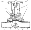
- FIG. 1 shows a diaphragm valve comprising a housing lower part 1, which terminals 2, 3 and 4 has a weir.
- the weir 4 serves as a seat for the membrane 5.
- the membrane 5 is clamped by means of connecting means 6, which are designed in the embodiment as screws.
- the membrane 5 is clamped between the lower housing part 1 and an upper housing part 7.
- a drive 8 which is designed in the embodiment as a handwheel, and a spindle 9.
- a pressure piece 10 is attached on the spindle 9.
- the pressure piece 10 is arranged displaceably in the upper housing part 7 and is guided by an inner wall of the upper housing part 7.
- a pin-like element 11 is embedded, which is formed in the embodiment as a membrane screw.
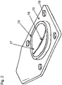
- FIG. 2 shows a plan view of a membrane 5 for a chambered use.
- a chamber is formed by the lower housing part 1 and the upper housing part 7, which receives an edge bead 12 of the membrane 5.
- the edge bead 12 is for example in FIG. 3 shown.
- the shape and the volume of the Randwulstes 12 are chosen so that when tightening the connecting means 6, a deformation and a pressing of the edge bead 12 occurs within the chamber. The edge bead 12 is thus fixed and close to the wall of the chamber.
- membrane 5 has a circumferential outer sealing lip 15 to ensure the tightness of the housing. Furthermore, the membrane 5 has a sealing lip 16 to ensure the tightness in the passage.
- the membrane 5 is divided into an inner region 17 and an outer region 18.
- the inner region 17 is circular and comprises a surface curved between the sealing lip 15 and the sealing lip 16 and the sealing lip 15 itself.
- the inner region 17 is circular ,
- the inner region 17 is followed immediately by an outer region 18.
- the outer region 18 has openings 19 for the passage of the connecting means 6.
- the outer region 18 is formed at its edges with straight edges and has, where it is clamped between the housing parts 1 and 7, a rectangular profile.
- the outer region 18 is arranged around the circular inner region 17.
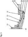
- FIG. 3 shows a section through the in FIG. 2 represented membrane 5, wherein as shown in FIG. 3 only the right half of the membrane 5 is shown with respect to the drawing.
- the mirror-symmetrical to the axis 20 belonging half is in FIG. 3 not shown.
- the axis 20 forms the mirror-symmetrical central axis of the membrane 5.
- the in FIG. 3 represented membrane around a composite membrane having an inner region 17, to which an outer region 18 connects.
- the outer region 18 has a greater hardness relative to the inner region 17.
- the outer area 18 consists of another Material than the inner region 17.
- the inner region 17 consists of an elastomer.
- the elastomer is an ethylene-propylene-diene rubber (EPDM).
- EPDM ethylene-propylene-diene rubber
- the elastomeric inner region 17 comprises two elastomer layers, between which a fabric layer 21 is arranged.
- the inner region 17 has a circumferential sealing lip 15 for sealing against the housing parts 1 and 7 and a sealing lip 16 which cooperates with the seat 4 of the valve.
- the circumferential sealing lip 15 is annular and has the side of the sealing lip 16th
- the outer region 18 adjoins directly to the inner region 17.
- the contact surface 22 between the inner region 17 and the outer region 18 is formed obliquely in relation to the end faces of the lower housing part 1 and the upper housing part between which the membrane is clamped.
- the contact surface 22 extends obliquely to the valve seat.
- the inner region 17 is firmly connected to the outer region 18, for example via a bond.
- a space 23 is formed, in which a spring element 24 is arranged.
- the spring element 24 may be, for example, a spiral spring or an elastic body.
- the spring element 24 serves to retighten the membrane 5.
- the spring element 24 acts on forces which are perpendicular to the end faces of the housing parts 1 and 7 between which the membrane 5 is clamped.
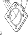
- FIG. 4 shows a plan view of a flat membrane.
- the membrane 5 has a circumferential outer sealing lip 15 to ensure the tightness of the housing. Furthermore, the membrane 5 has a sealing lip 16 to ensure the tightness in the passage.
- the membrane 5 is divided into an inner region 17 and an outer region 18.
- the inner region 17 is circular and comprises a surface curved between the sealing lip 15 and the sealing lip 16 and the sealing lip 15 itself.
- the inner region 17 is circular.
- the inner region 17 is followed immediately by an outer region 18.
- the outer region 18 has openings 19 for the passage of the connecting means 6.
- the outer region 18 is formed at its edges with straight edges and has, where it is clamped between the housing parts 1 and 7, a rectangular profile.
- the outer region 18 is arranged around the circular inner region 17.
- the outer region 18 forms a flag 25. This integrally formed lug 25 bears a mark for identifying the membrane 5.
- FIG. 5 shows a section through one half of the in FIG. 4 shown flat membrane 5, wherein only the right half of the membrane with respect to the drawing is shown.
- the mirror-symmetrical to the axis 20 belonging half is not shown.
- the axis 20 forms the mirror-symmetrical central axis of the membrane 5.
- the in FIG. 5 represented membrane 5 to a composite membrane having an inner region 17, to which an outer region 18 connects.
- the outer region 18 has a greater hardness relative to the inner region 17.
- the outer region 18 is made of a different material than the inner region 17.
- the inner region 17 consists of an elastomer.
- the elastomer is an ethylene-propylene-diene rubber (EPDM).
- EPDM ethylene-propylene-diene rubber
- the elastomeric inner region 17 comprises two elastomer layers, between which a fabric layer 21 is arranged.
- the inner region 17 has a circumferential sealing lip 15 for sealing against the housing parts 1 and 7 and a sealing lip 16 which cooperates with the seat 4 of the valve.
- the circumferential sealing lip 15 is annular and has the side of the sealing lip 16th
- the outer region 18 adjoins directly to the inner region 17.
- the contact surface 22 between the inner portion 17 and the outer portion 18 is formed parallel to the end faces of the housing lower part 1 and the upper housing part 7 between which the membrane is clamped.
- the inner region 17 is firmly connected to the outer region 18, for example via a bond.
- a space 23 is formed by walls of the inner area 17 and the outer area 18.
- the spring element 24 may be, for example, a spiral spring or an elastic body.
- the spring element 24 serves to retighten the membrane 5.
- the spring element 24 acts on forces which are perpendicular to the end faces of the housing parts 1 and 7 between which the membrane 5 is clamped.
- the space 23 is exclusively formed by walls of the inner area 17 and the outer area 18. In the inner area 17, a pin-like element 11 is positively integrated.
Landscapes
- Engineering & Computer Science (AREA)
- General Engineering & Computer Science (AREA)
- Mechanical Engineering (AREA)
- Diaphragms And Bellows (AREA)
Abstract
Veröffentlichung mit Fig. 3 Die Erfindung betrifft ein Membranventil mit einer Membran (5), die Räume voneinander dichtend trennt. Die Membran (5) ist zwischen mindestens zwei Gehäuseteilen (1, 7) angeordnet. Die Membran (5) weist einen inneren Bereich (17) auf, an den sich ein äußerer Bereich (18) anschließt. Der äußere Bereich (18) hat gegenüber dem inneren Bereich (17) eine höhere Härte.Publication with Fig. 3 The invention relates to a diaphragm valve with a membrane (5), the spaces from each other sealingly separates. The membrane (5) is arranged between at least two housing parts (1, 7). The membrane (5) has an inner region (17), which is adjoined by an outer region (18). The outer region (18) has a higher hardness compared to the inner region (17).
Description
Die Erfindung betrifft ein Membranventil mit einer Membran, die Räume voneinander dichtend trennt, wobei die Membran zwischen Gehäuseteilen angeordnet ist.The invention relates to a diaphragm valve with a membrane which seals spaces from each other, wherein the membrane is arranged between housing parts.
Membranventile können zur Dosierung von unterschiedlichen Fluiden eingesetzt werden, beispielsweise von Gasen, Dämpfen oder Flüssigkeiten. Beispielsweise können Membranventile eingesetzt werden, um hochviskose bzw. sehr stark haftfähige Medien zu dosieren bzw. zu verteilen. Bei Membranventilen wird dabei wirksam eine Ablagerung und somit auch eine Kontamination verhindert. Ventile auf Basis des Membranprinzips sind die totraumärmsten Dosierarmaturen. Neben dem sehr geringen Totraumvolumen sind Membranventile zudem entleerungsoptimiert konstruiert, sodass eine rückstandsfreie Entfernung des Mediums ermöglicht wird.Diaphragm valves can be used to dose different fluids, such as gases, vapors or liquids. For example, diaphragm valves can be used to meter or distribute highly viscous or very strongly adhesive media. In the case of diaphragm valves, this effectively prevents deposition and thus also contamination. Valves based on the membrane principle are the lowest-dead-weight dosing valves. In addition to the very low dead space volume, diaphragm valves are also designed to be emptying-optimized so that residue-free removal of the medium is possible.
Dies ist insbesondere bei pharmazeutischen Anlagen und Fertigungsprozessen von großer Bedeutung, da diese den hohen Ansprüchen einer strengen Validierung unterliegen, mit dem Ziel, eine gleichbleibende und reproduzierbare Qualität zu gewährleisten. Aus diesen Ansprüchen resultiert die Notwendigkeit, verschiedene Prozesse innerhalb einer Anlage fahren zu können. Neben dem eigentlichen Produktionsprozess sind dies in der Regel die Reinigung, Desinfektion und Sterilisation der Anlage. Membranventile haben sich aufgrund ihrer vorteilhaften Konstruktionsmerkmale als bevorzugte Armatur in der sterilen Prozesstechnik etabliert.This is particularly important in pharmaceutical plants and manufacturing processes, as these are subject to the strict requirements of strict validation, with the aim of ensuring a consistent and reproducible quality. These requirements result in the need to be able to drive various processes within a plant. In addition to the actual production process, these are usually the cleaning, disinfection and sterilization of the system. Diaphragm valves have established themselves as the preferred valve in the sterile process technology due to their advantageous design features.
Die eingesetzten Membranen bilden bewegliche, dichtende Wände, die zwei Räume mit in der Regel unterschiedlichen Medien (Gase, Flüssigkeiten) und häufig auch unterschiedlichen Druckverhältnissen voneinander trennen.The membranes used form movable, sealing walls that separate two rooms with generally different media (gases, liquids) and often also different pressure ratios.
Ein wichtiges Qualitätsmerkmal einer Membran ist deren Beweglichkeit, das heißt die Fähigkeit senkrecht zur Einspannfläche (Membranfläche) einen Hub auszuführen, der mechanisch angetrieben bedingt sein kann. Weiterhin ist die Beständigkeit der Membran von Bedeutung, insbesondere wenn aggressive Medien gefördert werden.An important quality feature of a membrane is its mobility, that is the ability perpendicular to the clamping surface (membrane surface) to perform a stroke that may be mechanically driven conditional. Furthermore, the durability of the membrane is important, especially when aggressive media are promoted.
Die Bewegungsfähigkeit und Beständigkeit einer Membran hängt im Wesentlichen vom Werkstoff ab, aus dem die Membran besteht. Als Grundwerkstoffe für Membranen werden hauptsächlich Elastomere verwendet, die zur Erzielung einer höheren Festigkeit mit Gewebeeinlagen verstärkt werden können. Als Elastomere haben sich Membranen mit Ethylen-Propylen-Dien-Kautschuk (EPDM) bewährt. Bei Ethylen-Propylen-Dien-Kautschuk (EPDM) handelt es sich um terpolymere Elastomere (Gummi) und somit um synthetische Kautschuke. Das Material zeichnet sich durch eine hohe Elastizität und gute chemische Beständigkeit aus.The mobility and durability of a membrane depends essentially on the material of which the membrane is made. As base materials for membranes mainly elastomers are used, which can be reinforced for greater strength with fabric inserts. As elastomers membranes have proven with ethylene-propylene-diene rubber (EPDM). Ethylene-propylene-diene rubber (EPDM) is a terpolymeric elastomer (rubber) and thus synthetic rubber. The material is characterized by a high elasticity and good chemical resistance.
In der
Der Einspannbereich einer Ventilmembran ist besonderen Anforderungen unterworfen. In erster Linie dient er der Halterung der Membran, deren Randbereich während des Schließens und in der Schließstellung einen radial nach innen gerichteten Zug ausgesetzt ist. Falls keine zusätzliche Abdichtung zwischen dem Unterteil und dem Oberteil des Gehäuses vorgesehen wird, kann der zwischen den Gehäuseteilen eingespannte Rand auch auf die Aufgabe der ruhenden Abdichtung übernehmen.The clamping area of a valve diaphragm is subject to special requirements. First and foremost, it serves to hold the membrane, the edge region of which is exposed during the closing and in the closed position, a radially inwardly directed train. If no additional seal between the base and the top is provided of the housing, the clamped between the housing parts edge can also take on the task of resting seal.
Die auf den Einspannbereich der Membran ausgeübte Dauerbeanspruchung führt, vor allem bei einem flachen Membranrand, oftmals zu einer gestaltlichen Veränderung, die schließlich zu einer Undichtigkeit des Gehäuses im betroffenen Bereich führen kann. Ein rechtzeitiges Nachspannen der den Membranrand beaufschlagenden Verschraubung vermag zwar den Zeitpunkt zu verschieben, an dem eine solche Undichtigkeit auftritt, sie kann den hierfür ursächlichen Prozess aber nicht aufhalten.The permanent stress exerted on the clamping area of the membrane often leads, especially in the case of a flat edge of the membrane, to a change in shape that can ultimately lead to a leakage of the housing in the affected area. Although a timely retightening of the membrane rim acting on screw connection is able to postpone the time at which such a leak occurs, but it can not stop the causal process.
Bei Membranen, die einen zwischen den Gehäuseteilen eingespannten Randwulst besitzen, ist die geschilderte Problematik nicht oder nur im geringen Maße gegeben. Die auf den Randwulst ausgeübten Flächenpressung muss nicht so hoch sein wie bei einem flachen Rand, da der großraumige Wulst sich der ihm aufnehmenden Kammer anpasst, sodass eine gute Abdichtung sichergestellt ist. Die Kammerung des Einspannbereiches stellt eine dauerhafte Halterung sicher.For membranes, which have a clamped between the housing parts edge bead, the problem is not or only to a small extent given. The surface pressure exerted on the edge bead need not be as high as a flat edge, as the large-diameter bead adapts to the receiving chamber, so that a good seal is ensured. The chambering of the clamping area ensures a permanent holder.
Die an sich vorteilhafte Kammerung des Randwulstes birgt jedoch ein Problem in sich, das seine Ursache in einer nicht auszuschließenden unsachgemäßen Montage oder Wartung hat. Wird nämlich das von dem Hersteller eines solchen Membranventils vorgeschriebene Anzugsdrehmoment der Verschraubung um ein erhebliches Maß überschritten, so erfolgt eine radial nach innen gerichtete Verdrängung eines Teils des Membranmaterials des Randwulstes. An der rundum verlaufenden die Kammer begrenzenden Engstelle, die durch die beiden Gehäuseteile gebildet wird, ergibt sich so eine Materialanhäufung, die vor allem während der Membranbetätigung zu Spannungen in diesem und im benachbarten Membranbereich führt. Diese Spannungen können zu einem Einreißen der Membranoberfläche und zumindest bei Membranen ohne Faserverstärkung schließlich zu einem Membranbruch führen.However, the per se advantageous Kammerung the edge bead entails a problem in itself, which has its cause in a non-exclude improper installation or maintenance. Namely, if the prescribed by the manufacturer of such a diaphragm valve tightening torque of the screw is exceeded by a considerable amount, there is a radially inwardly directed displacement of a portion of the membrane material of the edge bead. At the all around extending the chamber limiting bottleneck, which is formed by the two housing parts, this results in an accumulation of material, which leads to stresses in this and in the adjacent membrane area, especially during the membrane actuation. These tensions can eventually lead to a rupture of the membrane surface and, at least in membranes without fiber reinforcement, ultimately to a membrane rupture.
Um ein über ein vorgeschriebenes Maß hinausgehendes Anziehen der Verschraubung zu vermeiden, könnten der Randwulst, die diesen aufnehmende Kammer und die Stirnflächen von Gehäuseunter- und -oberteil so gestaltet und bemessen werden, dass die maximal zulässige Pressung des Randwulstes erreicht wäre, wenn die Stirnflächen der Gehäuseteile zur Anlage aneinander kämen. Dies würde aber wegen der notwendigen Präzision einen hohen Aufwand bei der Fertigung der Membranen und der Gehäuseteile und möglicherweise zusätzlicher Anpassungsarbeiten notwendig machen.In order to avoid a tightening beyond the prescribed extent of the screw, the edge bead, this receiving chamber and the end faces of housing lower and upper part could be designed and dimensioned so that the maximum allowable pressure of the edge bead would be achieved if the end faces of the housing parts would come to rest against each other. However, this would necessitate a great deal of effort in the manufacture of the membranes and the housing parts and possibly additional adaptation work because of the necessary precision.
Aufgabe der Erfindung ist es, ein Membranventil bereitzustellen, bei dem eine Fehlmontage der Membran durch zu starkes Anziehen und damit eine zu starke Verpressung verhindert wird. Das Membranventil soll sich durch eine preiswerte Herstellungsweise und eine hohe Lebensdauer auszeichnen. Zudem soll das Membranventil möglichst wartungsfrei sein und eine hohe Dichtigkeit gewährleisten. Weiterhin soll sich das Membranventil durch ein möglichst geringes Totvolumen und eine gute Reinigungsfähigkeit auszeichnen, sodass insbesondere die Anforderungen für einen hochsterilen Einsatz erfüllt werden.The object of the invention is to provide a diaphragm valve, in which a faulty mounting of the membrane is prevented by excessive tightening and thus excessive compression. The diaphragm valve should be characterized by an inexpensive manufacturing method and a long service life. In addition, the diaphragm valve should be as maintenance-free and ensure a high density. Furthermore, the membrane valve should be characterized by the lowest possible dead volume and a good cleanability, so that in particular the requirements for a highly sterile use are met.
Diese Aufgabe wird erfindungsgemäß durch ein Membranventil mit den Merkmalen des Anspruchs 1 gelöst. Bevorzugte Ausführungsformen sind der Beschreibung, den Zeichnungen und den Unteransprüchen zu entnehmen.This object is achieved by a diaphragm valve with the features of
Erfindungsgemäß umfasst das Membranventil eine Membran, die einen inneren Bereich aufweist, an den sich ein äußerer Bereich anschließt, der eine höhere Härte aufweist. Die Shore-Härte ist eine Kennzahl, die vorwiegend für Polymere eingesetzt wird. Sie steht in direkter Beziehung zur Eindringtiefe und ist somit ein Maß für die Werkstoffhärte. Nach DIN 53505 unterscheidet man zwischen den Verfahren Shore A, C und D. Als Eindringkörper (Indenter) wird häufig ein federbelasteter Stift aus gehärtetem Stahl verwendet. Bei diesem Verfahren wird der jeweilige Indenter mit der Federkraft in den Prüfkörper gedrückt und die Eindringtiefe stellt somit ein Maß für die Shore-Härte dar. Dadurch wirkt der äußere Bereich als Stützbereich. Dieser äußere Stützbereich kann die Funktion eines Distanzelements übernehmen. Dadurch wird eine Fehlmontage der Membran durch zu starkes Anziehen und damit eine zu starke Verpressung verhindert.According to the invention, the membrane valve comprises a membrane having an inner region, followed by an outer region having a higher hardness. The Shore hardness is a key figure that is mainly used for polymers. It is directly related to the penetration depth and is thus a measure of the material hardness. According to DIN 53505, a distinction is made between the methods Shore A, C and D. As indenter (indenter) often a spring-loaded pin made of hardened steel is used. In this method, the respective indenter is pressed with the spring force in the test specimen and the penetration depth thus represents a measure of the Shore hardness. Thus, the outer area acts as a support area. This outer support area can take over the function of a spacer element. As a result, incorrect assembly of the membrane is prevented by over-tightening and thus excessive compression.
Vorzugsweise weist der innere Bereich eine Härte nach Shore-A auf, wobei es sich als günstig erweist, wenn die Härte des inneren Bereichs bei Shore-A zwischen 50 und 90 liegt.Preferably, the inner region has a Shore A hardness, and it proves to be favorable if the hardness of the inner region at Shore A is between 50 and 90.
Der äußere Bereich weist vorzugsweise eine Härte nach Shore-D auf, wobei es sich als günstig erweist, wenn die Härte des äußeren Bereichs bei Shore-D größer als 50 liegt.The outer region preferably has a Shore-D hardness, and it proves to be favorable if the hardness of the outer region at Shore-D is greater than 50.
Bei einer besonders vorteilhaften Variante der Erfindung weist der innere Bereich ein Elastizitätsmodul von weniger als 45 MPa, vorzugsweise weniger als 35 MPa, insbesondere weniger als 25 MPa auf.In a particularly advantageous variant of the invention, the inner region has a modulus of elasticity of less than 45 MPa, preferably less than 35 MPa, in particular less than 25 MPa.
Bei einer günstigen Ausführung der Erfindung weist der äußere Bereich ein Elastizitätsmodul von mehr als 300 MPa, vorzugsweise mehr als 400 MPa, insbesondere mehr als 500 MPa auf.In a favorable embodiment of the invention, the outer region has a modulus of elasticity of more than 300 MPa, preferably more than 400 MPa, in particular more than 500 MPa.
Vorzugsweise besteht der innere Bereich der Membran aus einem elastomeren Werkstoff. Vorzugsweise aus Ethylen-Propylen-Dien-Kautschuk (EPDM). Bei einer Variante der Erfindung kann der innere Bereich eine Gewebeeinlage aufweisen. Beispielsweise kann der innere Bereich aus zwei Elastomerlagen bestehen, zwischen denen eine Gewebeeinlage angeordnet ist. Die Gewebeeinlagen verstärken den inneren Bereich der Membran.Preferably, the inner region of the membrane is made of an elastomeric material. Preferably from ethylene-propylene-diene rubber (EPDM). In a variant of the invention, the inner region may comprise a fabric insert. For example, the inner region consist of two elastomer layers, between which a fabric insert is arranged. The fabric inserts reinforce the inner region of the membrane.
Der äußere Bereich der Membran besteht vorzugsweise aus einem thermoplastischen und/oder duroplastischen Werkstoff. Bei Thermoplasten, die manchmal auch als Plastomere bezeichnet werden, handelt es sich um Kunststoffe, die sich in einem bestimmten Temperaturbereich verformen lassen. Bei einer besonders günstigen Ausführung der Erfindung besteht der äußere Bereich der Membran aus einem Duroplast. Duroplaste sind Kunststoffe, die nach ihrer Aushärtung nicht mehr verformt werden können. Es handelt sich dabei meist um relativ harte, glasartige Polymerwerkstoffe, die über chemische Hauptvalenzverbindungen dreidimensional fest vernetzt sind. Üblicherweise können Duroplaste ebenso wie Elastomere aufgrund ihrer Vernetzung nicht ausgeschmolzen werden und zerfallen nach Überschreiten der Zersetzungstemperatur (Pyrolyse). Als Duroplaste können beispielsweise Aminoplaste oder Phenoplaste eingesetzt werden. Auch der Einsatz von Epoxidharzen bzw. vernetzten Polyacrylaten zur Fertigung des äußeren Bereichs der Membran ist denkbar.The outer region of the membrane is preferably made of a thermoplastic and / or thermosetting material. Thermoplastics, sometimes referred to as plastomers, are plastics that deform within a certain temperature range. In a particularly favorable embodiment of the invention, the outer region of the membrane consists of a duroplastic material. Thermosets are plastics that can not be deformed after they have hardened. These are usually relatively hard, glassy polymer materials, which are firmly cross-linked via chemical Hauptvalenzverbindungen three-dimensional. Usually thermosets as well as elastomers can not be melted out due to their crosslinking and disintegrate after exceeding the decomposition temperature (Pyrolysis). As thermosets, for example, aminoplasts or phenoplasts can be used. The use of epoxy resins or crosslinked polyacrylates for the production of the outer region of the membrane is conceivable.
Durch den Einsatz dieser Werkstoffe wird bei einer bevorzugten Variante der Erfindung eine Identifizierung der Membran durch eine Einfärbung des äußeren Bereichs bewirkt. Die erfinderische Gestaltung des äußeren Bereichs der Membran aus einem Thermoplast oder einem Duroplast vereinfacht eine farbliche Identifizierung der Membran, da Thermoplaste oder Duroplaste gut einfärbbar sind und die Farbe keinen Einfluss auf die Bewegungseigenschaften und Dichtungseigenschaften der Membran hat.Through the use of these materials, in a preferred variant of the invention, identification of the membrane is effected by coloring the outer area. The inventive design of the outer region of the membrane made of a thermoplastic or a thermoset simplified color identification of the membrane, since thermoplastics or thermosets are well dyed and the color has no influence on the movement properties and sealing properties of the membrane.
Die erfindungsgemäße Komposit-Membran ermöglicht gegenüber herkömmlichen Membranen eine Veränderung des Kraftflusses beim Einspannen der Membran zwischen zwei Gehäuseteilen. Durch die Gestaltung des äußeren Bereichs der Komposit-Membran aus einem härteren Werkstoff wird die Dichtung in einen Kraftnebenschluss verlegt. In einer besonders günstigen Ausführung der Erfindung überträgt der äußere Bereich der Membran dabei mehr als 60 %, vorzugsweise mehr als 70 %, insbesondere mehr als 80 % der Kräfte zwischen den Verbindungselementen der Gehäuseteile, welche die Membran einspannen. Bei den Verbindungselementen kann es sich beispielsweise um Schrauben handeln. Diese Änderung des Kraftflusses wird durch die erfindungsgemäße Gestaltung des äußeren Bereichs der Membran bewirkt, der aufgrund seiner höheren Härte als Stützring wirkt. Die erfindungsgemäße Komposit-Membran ermöglicht es, dass der innere Bereich ausschließlich die Bewegungsfunktion und die Abdichtung gegenüber dem Ventildurchgang übernimmt. Dagegen übernimmt der innere Bereich beim Einspannen der Membran zwischen den Gehäuseteilen nur einen geringeren Teil der Schraubenkraft.Compared to conventional membranes, the composite membrane according to the invention allows a change in the flow of force during clamping of the membrane between two housing parts. By designing the outer portion of the composite membrane of a harder material, the seal is placed in a force shunt. In a particularly favorable embodiment of the invention, the outer region of the membrane transmits more than 60%, preferably more than 70%, in particular more than 80%, of the forces between the connecting elements of the housing parts, which clamp the membrane. The connecting elements may be, for example, screws. This change in the power flow is effected by the inventive design of the outer region of the membrane, which acts as a support ring due to its higher hardness. The composite membrane according to the invention makes it possible for the inner region to assume exclusively the movement function and the seal with respect to the valve passage. By contrast, the inner area takes on only a smaller part of the screw force when clamping the membrane between the housing parts.
Vorzugsweise schließt sich der äußere Bereich unmittelbar an den inneren Bereich an. Bei einer besonders günstigen Variante der Erfindung sind der innere und der äußere Bereich miteinander verbunden und bilden eine Einheit. Die Verbindung der beiden unterschiedlichen Materialien kann beispielsweise über eine Verklebung des inneren mit dem äußeren Bereich erfolgen. Daher wird eine nicht-lösbare Verbindung zwischen dem äußeren und dem inneren Bereich geschaffen, sodass ein einheitliches Membranelement entsteht. Vorzugsweise handelt es sich bei der Verbindung zwischen dem äußeren und dem inneren Bereich der Membran um ein stoffschlüssiges Fügeverfahren. Beispielsweise können die beiden Bereiche durch einen Klebstoff stoffschlüssig verbunden werden.Preferably, the outer region directly adjoins the inner region. In a particularly favorable variant of the invention, the inner and outer regions are connected to one another and form a unit. The connection of the two different materials can be done for example by bonding the inner to the outer region. Therefore, a non-detachable connection between created the outer and the inner region, so that a uniform membrane element is formed. Preferably, the connection between the outer and the inner region of the membrane is a cohesive joining process. For example, the two areas can be adhesively bonded by an adhesive.
Die Verbindungsflächen zwischen dem inneren und dem äußeren Bereich können beispielsweise senkrecht zu den Stirnflächen der beiden Gehäuseteile verlaufen zwischen denen die Membran eingespannt ist. Bei einer besonders günstigen Variante der Erfindung grenzen der innere und der äußere Bereich über Schrägflächen aneinander. Diese Flächen sind somit nicht senkrecht, sondern schräg zu den Stirnflächen der bindenden Gehäuseteile ausgerichtet. Vorzugsweise verläuft dabei die Schrägstellung in Richtung des Ventilsitzes.The connecting surfaces between the inner and the outer region can for example be perpendicular to the end faces of the two housing parts between which the membrane is clamped. In a particularly favorable variant of the invention, the inner and outer regions adjoin one another via inclined surfaces. These surfaces are thus not perpendicular, but aligned obliquely to the end faces of the binding housing parts. Preferably, the inclined position runs in the direction of the valve seat.
Der äußere und der innere Bereich der Membran können auch über Flächen verbunden sein, die parallel zu den Stirnflächen der verbindenden Gehäuseteile verlaufen.The outer and inner regions of the membrane may also be connected via surfaces which run parallel to the end faces of the connecting housing parts.
Bei einer besonders vorteilhaften Ausgestaltung der Erfindung weist die Membran ein federndes Element auf. Vorzugsweise ist das federnde Element in einem Raum angeordnet. Dabei erweist es sich als günstig, wenn sich der Raum zwischen dem ersten und dem zweiten Bereich befindet bzw. der Raum zumindest teilweise von Wänden des ersten Bereichs bzw. und/oder Wänden des zweiten Bereichs begrenzt wird. Bei dem federnden Element kann es sich beispielsweise um eine Membranfeder oder einen elastischen Körper handeln. Die Erfindung umfasst auch Varianten, bei denen das federnde Element ausschließlich im inneren Bereich oder im äußeren Bereich angeordnet ist. Es gibt auch Varianten, bei denen mehrere federnde Elemente zum Einsatz kommen. Vorzugsweise handelt es sich bei den federnden Elementen um ringförmig ausgebildete Elemente, die entlang des äußeren Dichtbereichs der Membran wirken. Die federnden Elemente bewirken ein Nachspannen der Elastomerdichtung. Durch die erfindungsgemäße Kombination einer Komposit-Membran mit einem inneren und einem äußeren Bereich und gleichzeitig eingebauten Federelementen wird eine Anordnung geschaffen, die eine hohe Dichtigkeit und eine lange Lebensdauer aufweist. Bei diesem erfindungsgemäßen Membranventil werden Fehlmontagen wirksam verhindert und gleichzeitig wird eine hohe Zuverlässigkeit gewährleistet. Die Kräfte des federnden Elementes wirken vorzugsweise senkrecht zu den Stirnflächen der Gehäuseteile zwischen denen die Membran eingespannt ist.In a particularly advantageous embodiment of the invention, the membrane has a resilient element. Preferably, the resilient element is arranged in a space. It proves to be advantageous if the space between the first and the second area is or the space is at least partially bounded by walls of the first area and / or walls of the second area. The resilient element may be, for example, a diaphragm spring or an elastic body. The invention also includes variants in which the resilient element is arranged exclusively in the inner region or in the outer region. There are also variants in which several resilient elements are used. Preferably, the resilient elements are annularly shaped elements which act along the outer sealing region of the membrane. The resilient elements cause a re-tensioning of the elastomeric seal. The inventive combination of a composite membrane with an inner and an outer region and simultaneously installed spring elements, an arrangement is provided which has a high density and a long life. In this inventive diaphragm valve incorrect assembly are effectively prevented and at the same time a high reliability is guaranteed. The forces of the resilient element preferably act perpendicular to the end faces of the housing parts between which the membrane is clamped.
Bei einer besonders günstigen Variante der Erfindung weist die Komposit-Membran zudem eine umlaufende Dichtlippe auf.In a particularly favorable variant of the invention, the composite membrane also has a circumferential sealing lip.
Die Komposit-Membran kann gekammert oder flach ausgebildet sein. Insbesondere bei einer gekammerten Variante erweist es sich als günstig, wenn die erfindungsgemäße Komposit-Membran einen Randwulst aufweist.The composite membrane may be chambered or flat. In particular, in a chambered variant, it proves to be advantageous if the composite membrane according to the invention has an edge bead.
Bei einer vorteilhaften Ausführung der Erfindung weist die Komposit-Membran ergänzend oder alternativ eine Durchgangs-Dichtlippe auf, die mit dem Sitz des Membranventils zusammenwirkt. Als besonders günstig erweist es sich, wenn der innere Bereich der Membran eine kreisförmige Ausgestaltung aufweist. Die Durchgangs-Dichtlippe kann dabei als Gerade ausgebildet sein, die durch den Mittelpunkt des Kreises verläuft. Vorzugsweise ist der innere, mittlere Bereich der Membran gewölbt ausgebildet.In an advantageous embodiment of the invention, the composite membrane additionally or alternatively on a passage sealing lip, which cooperates with the seat of the diaphragm valve. It proves to be particularly favorable when the inner region of the membrane has a circular configuration. The passage sealing lip may be formed as a straight line passing through the center of the circle. Preferably, the inner, central region of the membrane is curved.
Der äußere Bereich schließt sich unmittelbar an den kreisförmigen mittleren Bereich an, wobei die Außenkonturen des äußeren Bereichs der Membran vorzugsweise als gerade Kanten ausgebildet sind, sodass sie in besonders günstiger Weise zwischen den beiden Gehäuseteilen zum Einspannen wirken. Dabei erweist es sich als vorteilhaft, wenn der äußere Bereich der Membran Ausnehmungen für die Schrauben aufweist, mit denen die Membran zwischen den beiden Gehäuseteilen verspannt wird.The outer region adjoins directly to the circular central region, wherein the outer contours of the outer region of the membrane are preferably formed as straight edges, so that they act in a particularly favorable manner between the two housing parts for clamping. It proves to be advantageous if the outer region of the membrane has recesses for the screws, with which the membrane is clamped between the two housing parts.
Weitere Merkmale und Vorteile der Erfindung ergeben sich aus der Beschreibung von Ausführungsbeispielen anhand von Zeichnungen und aus den Zeichnungen selbst.Further features and advantages of the invention will become apparent from the description of embodiments with reference to drawings and from the drawings themselves.
Dabei zeigt:
Figur 1- eine Schnittdarstellung eines Membranventils,
Figur 2- eine Draufsicht auf eine gekammerte Membran,
Figur 3- eine Hälfte einer Schnittdarstellung einer gekammerten Membran,
Figur 4- eine Draufsicht auf eine flache Membran,
Figur 5- eine Hälfte eines Schnitts durch eine flache Membran.
- FIG. 1
- a sectional view of a diaphragm valve,
- FIG. 2
- a plan view of a chambered membrane,
- FIG. 3
- one half of a sectional view of a chambered membrane,
- FIG. 4
- a plan view of a flat membrane,
- FIG. 5
- a half of a section through a flat membrane.
In die Membran 5 ist ein stiftartiges Element 11 eingebettet, das im Ausführungsbeispiel als Membranschraube ausgebildet ist.In the
Mithilfe eines an das Gehäuseoberteil 7 angeformten Kragens 13 wird zwischen der Kammer und dem Gehäuseinneren 14 eine Engstelle gebildet, durch welche ein Herausziehen des Randwulstes 12 aus der Kammer verhindert wird.By means of an integrally formed on the upper housing part 7
Die in
Erfindungsgemäß ist die Membran 5 unterteilt in einen inneren Bereich 17 und einen äußeren Bereich 18. Der innere Bereich 17 ist kreisförmig ausgebildet und umfasst eine zwischen der Dichtlippe 15 gewölbte Fläche sowie die Dichtlippe 16 und die Dichtlippe 15 selbst. Der innere Bereich 17 ist kreisförmig ausgebildet. An den inneren Bereich 17 schließt sich unmittelbar ein äußerer Bereich 18 an. Der äußere Bereich 18 weist Öffnungen 19 zur Durchführung der Verbindungsmittel 6 auf. Der äußere Bereich 18 ist an seinen Rändern mit geraden Kanten ausgebildet und weist dort, wo er zwischen den Gehäuseteilen 1 und 7 eingespannt wird, ein rechteckförmiges Profil auf. Der äußere Bereich 18 ist um den kreisförmigen inneren Bereich 17 angeordnet.According to the invention, the
Erfindungsgemäß handelt es sich bei der in
Bei dem Elastomer handelt es sich um ein Ethylen-Propylen-Dien-Kautschuk (EPDM). Der elastomere innere Bereich 17 umfasst zwei Elastomerlagen, zwischen denen eine Gewebelage 21 angeordnet ist. Der innere Bereich 17 weist eine umlaufende Dichtlippe 15 zur Abdichtung gegenüber den Gehäuseteilen 1 und 7 und eine Dichtlippe 16 auf, die mit dem Sitz 4 des Ventils zusammenwirkt. Die umlaufende Dichtlippe 15 ist ringförmig ausgebildet und weist zur Seite der Dichtlippe 16.The elastomer is an ethylene-propylene-diene rubber (EPDM). The elastomeric
Der äußere Bereich 18 schließt sich unmittelbar an den inneren Bereich 17 an. Die Berührungsfläche 22 zwischen dem inneren Bereich 17 und dem äußeren Bereich 18 ist schräg ausgebildet im Verhältnis zu den Stirnflächen des Gehäuseunterteils 1 und des Gehäuseoberteils zwischen denen die Membran verspannt wird. Die Berührungsfläche 22 verläuft schräg zum Ventilsitz hin. Der innere Bereich 17 ist mit dem äußeren Bereich 18 fest verbunden, beispielsweise über eine Verklebung. Von den Wänden des Innenbereichs 17, des äußeren Bereichs 18 und dem Gehäuseunterteil 1 wird bei dem Ausführungsbeispiel gemäß
Erfindungsgemäß ist die Membran 5 unterteilt in einen inneren Bereich 17 und einen äußeren Bereich 18. Der innere Bereich 17 ist kreisförmig ausgebildet und umfasst eine zwischen der Dichtlippe 15 gewölbte Fläche sowie die Dichtlippe 16 und die Dichtlippe 15 selbst. Der innere Bereich 17 ist kreisförmig ausgebildet. An den inneren Bereich 17 schließt sich unmittelbar ein äußerer Bereich 18 an. Der äußere Bereich 18 weist Öffnungen 19 zur Durchführung der Verbindungsmittel 6 auf. Der äußere Bereich 18 ist an seinen Rändern mit geraden Kanten ausgebildet und weist dort, wo er zwischen den Gehäuseteilen 1 und 7 eingespannt wird, ein rechteckförmiges Profil auf. Der äußere Bereich 18 ist um den kreisförmigen inneren Bereich 17 angeordnet. Der äußere Bereich 18 bildet eine Fahne 25 aus. Diese angeformte Fahne 25 trägt ein Kennzeichen für eine Identifizierung der Membran 5.According to the invention, the
Erfindungsgemäß handelt es sich bei der in
Bei dem Elastomer handelt es sich um ein Ethylen-Propylen-Dien-Kautschuk (EPDM). Der elastomere innere Bereich 17 umfasst zwei Elastomerlagen, zwischen denen eine Gewebelage 21 angeordnet ist. Der innere Bereich 17 weist eine umlaufende Dichtlippe 15 zur Abdichtung gegenüber den Gehäuseteilen 1 und 7 und eine Dichtlippe 16 auf, die mit dem Sitz 4 des Ventils zusammenwirkt. Die umlaufende Dichtlippe 15 ist ringförmig ausgebildet und weist zur Seite der Dichtlippe 16.The elastomer is an ethylene-propylene-diene rubber (EPDM). The elastomeric
Der äußere Bereich 18 schließt sich unmittelbar an den inneren Bereich 17 an. Die Berührungsfläche 22 zwischen dem inneren Bereich 17 und dem äußeren Bereich 18 ist parallel zu den Stirnflächen des Gehäuseunterteils 1 und des Gehäuseoberteils 7 ausgebildet zwischen denen die Membran verspannt wird. Der innere Bereich 17 ist mit dem äußeren Bereich 18 fest verbunden, beispielsweise über eine Verklebung.The
Ein Raum 23 wird von Wänden des inneren Bereichs 17 und des äußeren Bereichs 18 gebildet. In dem Raum 23 ist in dem ein Federelement 24 angeordnet. Bei dem Federelement 24 kann es sich beispielsweise um eine Spiralfeder oder um einen elastischen Körper handeln. Das Federelement 24 dient dem Nachspannen der Membran 5. Das Federelement 24 wirkt Kräfte aus, die senkrecht zu den Stirnflächen der Gehäuseteile 1 und 7 zwischen denen die Membran 5 eingespannt ist. Der Raum 23 wird ausschließlich gebildet von Wänden des inneren Bereichs 17 und des äußeren Bereichs 18. In den inneren Bereich 17 ist ein stiftartige Element 11 formschlüssig integriert.A
Claims (17)
dadurch gekennzeichnet, dass
die Membran (5) einen inneren Bereich (17) aufweist, an den sich ein äußerer Bereich (18) anschließt, der eine höhere Härte aufweist.Diaphragm valve with a membrane (5) which seals spaces from each other, the membrane (5) being arranged between housing parts (1, 7),
characterized in that
the membrane (5) has an inner region (17), adjoined by an outer region (18) having a higher hardness.
Applications Claiming Priority (1)
| Application Number | Priority Date | Filing Date | Title |
|---|---|---|---|
| DE102016122302 | 2016-11-21 |
Publications (2)
| Publication Number | Publication Date |
|---|---|
| EP3324084A1 true EP3324084A1 (en) | 2018-05-23 |
| EP3324084B1 EP3324084B1 (en) | 2020-11-18 |
Family
ID=60452408
Family Applications (1)
| Application Number | Title | Priority Date | Filing Date |
|---|---|---|---|
| EP17202807.8A Active EP3324084B1 (en) | 2016-11-21 | 2017-11-21 | Membrane valve |
Country Status (1)
| Country | Link |
|---|---|
| EP (1) | EP3324084B1 (en) |
Cited By (3)
| Publication number | Priority date | Publication date | Assignee | Title |
|---|---|---|---|---|
| DE102017128996A1 (en) * | 2017-12-06 | 2019-06-06 | Gemü Gebr. Müller Apparatebau Gmbh & Co. Kommanditgesellschaft | Membrane for a diaphragm valve |
| EP3604873A1 (en) * | 2018-08-03 | 2020-02-05 | SISTO Armaturen S.A. | Membrane with flap |
| DE102020126105A1 (en) | 2020-10-06 | 2022-04-07 | Sisto Armaturen S.A. | Diaphragm assembly with reinforcement elements |
Families Citing this family (2)
| Publication number | Priority date | Publication date | Assignee | Title |
|---|---|---|---|---|
| DE102021119356A1 (en) | 2021-07-27 | 2023-02-02 | Sisto Armaturen S.A. | Multi-part pressure piece |
| DE102021119355A1 (en) | 2021-07-27 | 2023-02-02 | Sisto Armaturen S.A. | Diaphragm arrangement with cross-section narrowing elements |
Citations (10)
| Publication number | Priority date | Publication date | Assignee | Title |
|---|---|---|---|---|
| AU1669870A (en) * | 1969-07-04 | 1972-01-06 | Saunders Valve Company Limited | Flow control valves |
| DE2307580A1 (en) * | 1973-02-16 | 1974-09-05 | Klein Schanzlin & Becker Ag | DIAPHRAGM VALVE |
| DE3447329A1 (en) * | 1984-12-24 | 1986-07-03 | Saunders-Sisto Armaturen S.A., Mersch | Diaphragm valve |
| US5127625A (en) * | 1990-02-19 | 1992-07-07 | Avl Medical Instruments Ag | Electromagnetically actuated valve |
| DE19505747A1 (en) | 1995-02-20 | 1996-08-22 | Sisto Armaturen Sa | Membrane valve with flap extension |
| US20020135646A1 (en) * | 2000-07-07 | 2002-09-26 | Minoru Usui | Ink feed unit for ink jet recorder and diaphragm valve |
| JP2003226028A (en) * | 2002-02-04 | 2003-08-12 | Seiko Epson Corp | Membrane valve for differential pressure regulating valve, method of manufacturing the same and ink supply vessel |
| US20040099311A1 (en) * | 2002-11-27 | 2004-05-27 | Smc Kabushiki Kaisha | Two-way valve |
| JP2005133767A (en) * | 2003-10-28 | 2005-05-26 | Sekisui Chem Co Ltd | Diaphragm valve |
| DE102014013512A1 (en) * | 2014-09-11 | 2016-03-17 | Festo Ag & Co. Kg | diaphragm valve |
-
2017
- 2017-11-21 EP EP17202807.8A patent/EP3324084B1/en active Active
Patent Citations (10)
| Publication number | Priority date | Publication date | Assignee | Title |
|---|---|---|---|---|
| AU1669870A (en) * | 1969-07-04 | 1972-01-06 | Saunders Valve Company Limited | Flow control valves |
| DE2307580A1 (en) * | 1973-02-16 | 1974-09-05 | Klein Schanzlin & Becker Ag | DIAPHRAGM VALVE |
| DE3447329A1 (en) * | 1984-12-24 | 1986-07-03 | Saunders-Sisto Armaturen S.A., Mersch | Diaphragm valve |
| US5127625A (en) * | 1990-02-19 | 1992-07-07 | Avl Medical Instruments Ag | Electromagnetically actuated valve |
| DE19505747A1 (en) | 1995-02-20 | 1996-08-22 | Sisto Armaturen Sa | Membrane valve with flap extension |
| US20020135646A1 (en) * | 2000-07-07 | 2002-09-26 | Minoru Usui | Ink feed unit for ink jet recorder and diaphragm valve |
| JP2003226028A (en) * | 2002-02-04 | 2003-08-12 | Seiko Epson Corp | Membrane valve for differential pressure regulating valve, method of manufacturing the same and ink supply vessel |
| US20040099311A1 (en) * | 2002-11-27 | 2004-05-27 | Smc Kabushiki Kaisha | Two-way valve |
| JP2005133767A (en) * | 2003-10-28 | 2005-05-26 | Sekisui Chem Co Ltd | Diaphragm valve |
| DE102014013512A1 (en) * | 2014-09-11 | 2016-03-17 | Festo Ag & Co. Kg | diaphragm valve |
Cited By (6)
| Publication number | Priority date | Publication date | Assignee | Title |
|---|---|---|---|---|
| DE102017128996A1 (en) * | 2017-12-06 | 2019-06-06 | Gemü Gebr. Müller Apparatebau Gmbh & Co. Kommanditgesellschaft | Membrane for a diaphragm valve |
| EP3604873A1 (en) * | 2018-08-03 | 2020-02-05 | SISTO Armaturen S.A. | Membrane with flap |
| EP3604873B1 (en) | 2018-08-03 | 2021-06-02 | SISTO Armaturen S.A. | Membrane with flap |
| DE102020126105A1 (en) | 2020-10-06 | 2022-04-07 | Sisto Armaturen S.A. | Diaphragm assembly with reinforcement elements |
| EP3982017A1 (en) | 2020-10-06 | 2022-04-13 | SISTO Armaturen S.A. | Membrane assembly with reinforcing elements |
| EP4119819A1 (en) | 2020-10-06 | 2023-01-18 | SISTO Armaturen S.A. | Membrane assembly with reinforcing elements |
Also Published As
| Publication number | Publication date |
|---|---|
| EP3324084B1 (en) | 2020-11-18 |
Similar Documents
| Publication | Publication Date | Title |
|---|---|---|
| EP3324084B1 (en) | Membrane valve | |
| EP2140188B1 (en) | Valve for separating product media in the pipes of a product-carrying system | |
| DE102012005119B4 (en) | diaphragm valve | |
| DE112010003557T5 (en) | butterfly valve | |
| DE2416071B2 (en) | Sealing arrangement for lift valves | |
| DE102010030298A1 (en) | Multi-part valve disc | |
| EP2028377B1 (en) | Membrane actuator and method for manufacturing a membrane actuator | |
| EP3203124B1 (en) | Elastomer membrane element | |
| EP1418367A2 (en) | Annular gasket | |
| EP3366961B1 (en) | Membrane valve with free passthrough | |
| WO2019034401A1 (en) | Seal arrangement | |
| DE102013215294A1 (en) | Membrane arrangement for a valve device | |
| EP3978751B1 (en) | Composite membrane for membrane pumps | |
| EP1561986A1 (en) | Pipe fitting | |
| DE10231920A1 (en) | Multi-layer diaphragm | |
| EP2962017B1 (en) | Flat sealing for flange connections | |
| DE102017107844B4 (en) | Three-way ball valve, method for manufacturing and assembling such a ball valve | |
| DE10329024A1 (en) | Seal for a rotary valve of a coolant thermostat | |
| DE102017213153A1 (en) | Double seat valve for aseptic product lines | |
| EP4184042A1 (en) | Diaphragm valve with a secondary seal | |
| EP4119819A1 (en) | Membrane assembly with reinforcing elements | |
| DE2935005A1 (en) | PUSHER FOR A DOUBLE SEAT VALVE | |
| EP2618033B1 (en) | Membrane valve | |
| EP2369207A1 (en) | Valve | |
| DE2436348A1 (en) | VALVE |
Legal Events
| Date | Code | Title | Description |
|---|---|---|---|
| PUAI | Public reference made under article 153(3) epc to a published international application that has entered the european phase |
Free format text: ORIGINAL CODE: 0009012 |
|
| STAA | Information on the status of an ep patent application or granted ep patent |
Free format text: STATUS: THE APPLICATION HAS BEEN PUBLISHED |
|
| AK | Designated contracting states |
Kind code of ref document: A1 Designated state(s): AL AT BE BG CH CY CZ DE DK EE ES FI FR GB GR HR HU IE IS IT LI LT LU LV MC MK MT NL NO PL PT RO RS SE SI SK SM TR |
|
| AX | Request for extension of the european patent |
Extension state: BA ME |
|
| STAA | Information on the status of an ep patent application or granted ep patent |
Free format text: STATUS: REQUEST FOR EXAMINATION WAS MADE |
|
| 17P | Request for examination filed |
Effective date: 20180810 |
|
| RBV | Designated contracting states (corrected) |
Designated state(s): AL AT BE BG CH CY CZ DE DK EE ES FI FR GB GR HR HU IE IS IT LI LT LU LV MC MK MT NL NO PL PT RO RS SE SI SK SM TR |
|
| STAA | Information on the status of an ep patent application or granted ep patent |
Free format text: STATUS: EXAMINATION IS IN PROGRESS |
|
| 17Q | First examination report despatched |
Effective date: 20190222 |
|
| GRAP | Despatch of communication of intention to grant a patent |
Free format text: ORIGINAL CODE: EPIDOSNIGR1 |
|
| STAA | Information on the status of an ep patent application or granted ep patent |
Free format text: STATUS: GRANT OF PATENT IS INTENDED |
|
| INTG | Intention to grant announced |
Effective date: 20200715 |
|
| GRAS | Grant fee paid |
Free format text: ORIGINAL CODE: EPIDOSNIGR3 |
|
| GRAA | (expected) grant |
Free format text: ORIGINAL CODE: 0009210 |
|
| STAA | Information on the status of an ep patent application or granted ep patent |
Free format text: STATUS: THE PATENT HAS BEEN GRANTED |
|
| AK | Designated contracting states |
Kind code of ref document: B1 Designated state(s): AL AT BE BG CH CY CZ DE DK EE ES FI FR GB GR HR HU IE IS IT LI LT LU LV MC MK MT NL NO PL PT RO RS SE SI SK SM TR |
|
| REG | Reference to a national code |
Ref country code: GB Ref legal event code: FG4D Free format text: NOT ENGLISH |
|
| REG | Reference to a national code |
Ref country code: CH Ref legal event code: EP |
|
| REG | Reference to a national code |
Ref country code: DE Ref legal event code: R096 Ref document number: 502017008242 Country of ref document: DE |
|
| REG | Reference to a national code |
Ref country code: IE Ref legal event code: FG4D Free format text: LANGUAGE OF EP DOCUMENT: GERMAN |
|
| REG | Reference to a national code |
Ref country code: AT Ref legal event code: REF Ref document number: 1336140 Country of ref document: AT Kind code of ref document: T Effective date: 20201215 |
|
| REG | Reference to a national code |
Ref country code: NL Ref legal event code: MP Effective date: 20201118 |
|
| PG25 | Lapsed in a contracting state [announced via postgrant information from national office to epo] |
Ref country code: GR Free format text: LAPSE BECAUSE OF FAILURE TO SUBMIT A TRANSLATION OF THE DESCRIPTION OR TO PAY THE FEE WITHIN THE PRESCRIBED TIME-LIMIT Effective date: 20210219 Ref country code: FI Free format text: LAPSE BECAUSE OF FAILURE TO SUBMIT A TRANSLATION OF THE DESCRIPTION OR TO PAY THE FEE WITHIN THE PRESCRIBED TIME-LIMIT Effective date: 20201118 Ref country code: PT Free format text: LAPSE BECAUSE OF FAILURE TO SUBMIT A TRANSLATION OF THE DESCRIPTION OR TO PAY THE FEE WITHIN THE PRESCRIBED TIME-LIMIT Effective date: 20210318 Ref country code: RS Free format text: LAPSE BECAUSE OF FAILURE TO SUBMIT A TRANSLATION OF THE DESCRIPTION OR TO PAY THE FEE WITHIN THE PRESCRIBED TIME-LIMIT Effective date: 20201118 Ref country code: NO Free format text: LAPSE BECAUSE OF FAILURE TO SUBMIT A TRANSLATION OF THE DESCRIPTION OR TO PAY THE FEE WITHIN THE PRESCRIBED TIME-LIMIT Effective date: 20210218 |
|
| PG25 | Lapsed in a contracting state [announced via postgrant information from national office to epo] |
Ref country code: SE Free format text: LAPSE BECAUSE OF FAILURE TO SUBMIT A TRANSLATION OF THE DESCRIPTION OR TO PAY THE FEE WITHIN THE PRESCRIBED TIME-LIMIT Effective date: 20201118 Ref country code: BG Free format text: LAPSE BECAUSE OF FAILURE TO SUBMIT A TRANSLATION OF THE DESCRIPTION OR TO PAY THE FEE WITHIN THE PRESCRIBED TIME-LIMIT Effective date: 20210218 Ref country code: PL Free format text: LAPSE BECAUSE OF FAILURE TO SUBMIT A TRANSLATION OF THE DESCRIPTION OR TO PAY THE FEE WITHIN THE PRESCRIBED TIME-LIMIT Effective date: 20201118 Ref country code: IS Free format text: LAPSE BECAUSE OF FAILURE TO SUBMIT A TRANSLATION OF THE DESCRIPTION OR TO PAY THE FEE WITHIN THE PRESCRIBED TIME-LIMIT Effective date: 20210318 Ref country code: LV Free format text: LAPSE BECAUSE OF FAILURE TO SUBMIT A TRANSLATION OF THE DESCRIPTION OR TO PAY THE FEE WITHIN THE PRESCRIBED TIME-LIMIT Effective date: 20201118 |
|
| REG | Reference to a national code |
Ref country code: LT Ref legal event code: MG9D |
|
| PG25 | Lapsed in a contracting state [announced via postgrant information from national office to epo] |
Ref country code: HR Free format text: LAPSE BECAUSE OF FAILURE TO SUBMIT A TRANSLATION OF THE DESCRIPTION OR TO PAY THE FEE WITHIN THE PRESCRIBED TIME-LIMIT Effective date: 20201118 |
|
| PG25 | Lapsed in a contracting state [announced via postgrant information from national office to epo] |
Ref country code: RO Free format text: LAPSE BECAUSE OF FAILURE TO SUBMIT A TRANSLATION OF THE DESCRIPTION OR TO PAY THE FEE WITHIN THE PRESCRIBED TIME-LIMIT Effective date: 20201118 Ref country code: SK Free format text: LAPSE BECAUSE OF FAILURE TO SUBMIT A TRANSLATION OF THE DESCRIPTION OR TO PAY THE FEE WITHIN THE PRESCRIBED TIME-LIMIT Effective date: 20201118 Ref country code: SM Free format text: LAPSE BECAUSE OF FAILURE TO SUBMIT A TRANSLATION OF THE DESCRIPTION OR TO PAY THE FEE WITHIN THE PRESCRIBED TIME-LIMIT Effective date: 20201118 Ref country code: EE Free format text: LAPSE BECAUSE OF FAILURE TO SUBMIT A TRANSLATION OF THE DESCRIPTION OR TO PAY THE FEE WITHIN THE PRESCRIBED TIME-LIMIT Effective date: 20201118 Ref country code: CZ Free format text: LAPSE BECAUSE OF FAILURE TO SUBMIT A TRANSLATION OF THE DESCRIPTION OR TO PAY THE FEE WITHIN THE PRESCRIBED TIME-LIMIT Effective date: 20201118 Ref country code: LU Free format text: LAPSE BECAUSE OF NON-PAYMENT OF DUE FEES Effective date: 20201121 Ref country code: LT Free format text: LAPSE BECAUSE OF FAILURE TO SUBMIT A TRANSLATION OF THE DESCRIPTION OR TO PAY THE FEE WITHIN THE PRESCRIBED TIME-LIMIT Effective date: 20201118 |
|
| REG | Reference to a national code |
Ref country code: BE Ref legal event code: MM Effective date: 20201130 |
|
| REG | Reference to a national code |
Ref country code: DE Ref legal event code: R097 Ref document number: 502017008242 Country of ref document: DE |
|
| PG25 | Lapsed in a contracting state [announced via postgrant information from national office to epo] |
Ref country code: MC Free format text: LAPSE BECAUSE OF FAILURE TO SUBMIT A TRANSLATION OF THE DESCRIPTION OR TO PAY THE FEE WITHIN THE PRESCRIBED TIME-LIMIT Effective date: 20201118 Ref country code: DK Free format text: LAPSE BECAUSE OF FAILURE TO SUBMIT A TRANSLATION OF THE DESCRIPTION OR TO PAY THE FEE WITHIN THE PRESCRIBED TIME-LIMIT Effective date: 20201118 |
|
| PLBE | No opposition filed within time limit |
Free format text: ORIGINAL CODE: 0009261 |
|
| STAA | Information on the status of an ep patent application or granted ep patent |
Free format text: STATUS: NO OPPOSITION FILED WITHIN TIME LIMIT |
|
| 26N | No opposition filed |
Effective date: 20210819 |
|
| PG25 | Lapsed in a contracting state [announced via postgrant information from national office to epo] |
Ref country code: AL Free format text: LAPSE BECAUSE OF FAILURE TO SUBMIT A TRANSLATION OF THE DESCRIPTION OR TO PAY THE FEE WITHIN THE PRESCRIBED TIME-LIMIT Effective date: 20201118 Ref country code: NL Free format text: LAPSE BECAUSE OF FAILURE TO SUBMIT A TRANSLATION OF THE DESCRIPTION OR TO PAY THE FEE WITHIN THE PRESCRIBED TIME-LIMIT Effective date: 20201118 |
|
| PG25 | Lapsed in a contracting state [announced via postgrant information from national office to epo] |
Ref country code: SI Free format text: LAPSE BECAUSE OF FAILURE TO SUBMIT A TRANSLATION OF THE DESCRIPTION OR TO PAY THE FEE WITHIN THE PRESCRIBED TIME-LIMIT Effective date: 20201118 |
|
| PG25 | Lapsed in a contracting state [announced via postgrant information from national office to epo] |
Ref country code: ES Free format text: LAPSE BECAUSE OF FAILURE TO SUBMIT A TRANSLATION OF THE DESCRIPTION OR TO PAY THE FEE WITHIN THE PRESCRIBED TIME-LIMIT Effective date: 20201118 |
|
| PG25 | Lapsed in a contracting state [announced via postgrant information from national office to epo] |
Ref country code: IS Free format text: LAPSE BECAUSE OF FAILURE TO SUBMIT A TRANSLATION OF THE DESCRIPTION OR TO PAY THE FEE WITHIN THE PRESCRIBED TIME-LIMIT Effective date: 20210318 Ref country code: TR Free format text: LAPSE BECAUSE OF FAILURE TO SUBMIT A TRANSLATION OF THE DESCRIPTION OR TO PAY THE FEE WITHIN THE PRESCRIBED TIME-LIMIT Effective date: 20201118 Ref country code: MT Free format text: LAPSE BECAUSE OF FAILURE TO SUBMIT A TRANSLATION OF THE DESCRIPTION OR TO PAY THE FEE WITHIN THE PRESCRIBED TIME-LIMIT Effective date: 20201118 Ref country code: CY Free format text: LAPSE BECAUSE OF FAILURE TO SUBMIT A TRANSLATION OF THE DESCRIPTION OR TO PAY THE FEE WITHIN THE PRESCRIBED TIME-LIMIT Effective date: 20201118 |
|
| PG25 | Lapsed in a contracting state [announced via postgrant information from national office to epo] |
Ref country code: MK Free format text: LAPSE BECAUSE OF FAILURE TO SUBMIT A TRANSLATION OF THE DESCRIPTION OR TO PAY THE FEE WITHIN THE PRESCRIBED TIME-LIMIT Effective date: 20201118 |
|
| PG25 | Lapsed in a contracting state [announced via postgrant information from national office to epo] |
Ref country code: BE Free format text: LAPSE BECAUSE OF NON-PAYMENT OF DUE FEES Effective date: 20201130 |
|
| P01 | Opt-out of the competence of the unified patent court (upc) registered |
Effective date: 20230713 |
|
| PGFP | Annual fee paid to national office [announced via postgrant information from national office to epo] |
Ref country code: GB Payment date: 20231123 Year of fee payment: 7 |
|
| PGFP | Annual fee paid to national office [announced via postgrant information from national office to epo] |
Ref country code: IT Payment date: 20231129 Year of fee payment: 7 Ref country code: IE Payment date: 20231122 Year of fee payment: 7 Ref country code: FR Payment date: 20231127 Year of fee payment: 7 Ref country code: DE Payment date: 20231123 Year of fee payment: 7 Ref country code: CH Payment date: 20231201 Year of fee payment: 7 Ref country code: AT Payment date: 20231124 Year of fee payment: 7 |