EP3203124B1 - Elastomer membrane element - Google Patents
Elastomer membrane element Download PDFInfo
- Publication number
- EP3203124B1 EP3203124B1 EP17150162.0A EP17150162A EP3203124B1 EP 3203124 B1 EP3203124 B1 EP 3203124B1 EP 17150162 A EP17150162 A EP 17150162A EP 3203124 B1 EP3203124 B1 EP 3203124B1
- Authority
- EP
- European Patent Office
- Prior art keywords
- membrane element
- elastomer membrane
- elastomer
- recess
- valve
- Prior art date
- Legal status (The legal status is an assumption and is not a legal conclusion. Google has not performed a legal analysis and makes no representation as to the accuracy of the status listed.)
- Active
Links
- 239000012528 membrane Substances 0.000 title claims description 86
- 229920001971 elastomer Polymers 0.000 title claims description 48
- 239000000806 elastomer Substances 0.000 title claims description 48
- 239000004744 fabric Substances 0.000 claims description 13
- 239000012530 fluid Substances 0.000 claims description 6
- 239000000463 material Substances 0.000 description 14
- 230000015572 biosynthetic process Effects 0.000 description 3
- 239000002184 metal Substances 0.000 description 3
- 230000008719 thickening Effects 0.000 description 3
- 229920002943 EPDM rubber Polymers 0.000 description 2
- 230000035508 accumulation Effects 0.000 description 2
- 238000009825 accumulation Methods 0.000 description 2
- 230000005540 biological transmission Effects 0.000 description 2
- 238000011161 development Methods 0.000 description 2
- 230000018109 developmental process Effects 0.000 description 2
- 230000001771 impaired effect Effects 0.000 description 2
- 230000007246 mechanism Effects 0.000 description 2
- 230000003014 reinforcing effect Effects 0.000 description 2
- 238000007789 sealing Methods 0.000 description 2
- 239000000109 continuous material Substances 0.000 description 1
- 230000008878 coupling Effects 0.000 description 1
- 238000010168 coupling process Methods 0.000 description 1
- 238000005859 coupling reaction Methods 0.000 description 1
- 230000000694 effects Effects 0.000 description 1
- 239000007788 liquid Substances 0.000 description 1
- 230000002093 peripheral effect Effects 0.000 description 1
Images


Classifications
-
- F—MECHANICAL ENGINEERING; LIGHTING; HEATING; WEAPONS; BLASTING
- F16—ENGINEERING ELEMENTS AND UNITS; GENERAL MEASURES FOR PRODUCING AND MAINTAINING EFFECTIVE FUNCTIONING OF MACHINES OR INSTALLATIONS; THERMAL INSULATION IN GENERAL
- F16K—VALVES; TAPS; COCKS; ACTUATING-FLOATS; DEVICES FOR VENTING OR AERATING
- F16K7/00—Diaphragm valves or cut-off apparatus, e.g. with a member deformed, but not moved bodily, to close the passage ; Pinch valves
- F16K7/12—Diaphragm valves or cut-off apparatus, e.g. with a member deformed, but not moved bodily, to close the passage ; Pinch valves with flat, dished, or bowl-shaped diaphragm
- F16K7/14—Diaphragm valves or cut-off apparatus, e.g. with a member deformed, but not moved bodily, to close the passage ; Pinch valves with flat, dished, or bowl-shaped diaphragm arranged to be deformed against a flat seat
- F16K7/16—Diaphragm valves or cut-off apparatus, e.g. with a member deformed, but not moved bodily, to close the passage ; Pinch valves with flat, dished, or bowl-shaped diaphragm arranged to be deformed against a flat seat the diaphragm being mechanically actuated, e.g. by screw-spindle or cam
Definitions
- the invention relates to an elastomeric membrane element according to the preamble of claim 1.
- Elastomer membrane elements are generally known.
- membranes are known which are firmly clamped on an edge between two valve housing parts.
- Metal inserts within a clamping edge of the membrane are also known.
- An example is the DE 2 307 580 A1 directed.
- US 6 079 692 A discloses a combined valve diaphragm and seal device which enables automatic control valves and other valves to be closed with an industry-standard grooved coupling instead of a plurality of screws through an outer flange on the valve body.
- US 2012/200047 A1 discloses a sealing arrangement comprising a fastening bolt, a reinforcing fabric, a rigid support, an elastomeric body and an elastomer film.
- US 2009/076464 A1 discloses a surgical portal assembly comprising a portal that is adapted to provide access to underlying tissue and has a longitudinal opening that extends along a longitudinal axis of the portal and defines proximal and distal ends, and a seal.
- AU 16698 70 A discloses a diaphragm valve with a laminated flexible diaphragm which is circumferentially between a shoulder on a housing part of the valve which surrounds the flow through the valve and a flange on an upper part which receives the diaphragm drive mechanism of the valve and fastens to the housing part is clamped.
- the membrane has a reduced thickness in the clamping zone.
- EP 2 952 790 A1 discloses an intermediate piece for a shut-off device, in particular a diaphragm valve, for fluids.
- a pressure piece can be arranged in the intermediate piece.
- the pressure piece has at least two locking slides for locking a locking member of a closure element.
- the intermediate piece has a cylinder in which the pressure piece can be guided axially.
- the intermediate piece has a recess which is arranged such that in an assembly position of the pressure piece the locking slides move into the recess and thus release the locking member.
- US 2006/162547 A1 discloses a membrane for membrane valves, in particular for liquid media, consisting of a support membrane and a membrane shield (sealing membrane) which are held on a central connecting pin.
- a stiffening element is arranged axially between the support membrane and the membrane shield.
- GB 2 399 616 A discloses a diaphragm for a diaphragm valve comprising a peripheral zone which in use is compressed between a flange provided on a valve body and a flange provided on a drive mechanism.
- An elastomer membrane element for a membrane valve comprising a working section for opening and closing a fluid channel of the membrane valve, and wherein the elastomer membrane element has a fastening section surrounding the working section for fixing the elastomer membrane element to a valve body of the membrane valve includes.
- a recess is arranged at least in sections between the working section and the fastening section, which makes it possible for residual deformations to flow from the working section into the recess during operation of the elastomeric membrane element, without the function of the working section being impaired thereby.
- the elastomer material flowing into the recess can prevent the closing of the fluid channel from being impaired by deformation of the working section on the medium side.
- the possibility of the elastomer material flowing into the recess can reduce the likelihood of wrinkling.
- a first contact surface of the fastening section on the medium side springs back in an unmounted state of the elastomer membrane element compared to a second contact surface which adjoins the recess radially inwards on the medium side.
- the recess opens towards the medium side of the membrane element. As a result, the recess is protected against influences from the dry side.
- the recess is arranged radially outside of a media-guided area. It can advantageously be achieved that the recess forms a receiving area for flowing material accumulations or residual deformations of the elastomer material and is not directly influenced by a fluid pressure or a membrane movement.
- the recess is annular, at least in sections. This makes it possible to create an essentially rotationally symmetrical working area.
- the essentially rotationally symmetrical working area can be easily deformed in and against an infeed direction, as a result of which a valve drive can be made weaker.
- the fastening section comprises an essentially rigid insert.
- the recess adjoins the rigid insert radially inwards.
- the rigid insert has an annular inner contour, at least in sections. This creates the basis for the rotationally symmetrical execution of the working section.
- the rotationally symmetrical design enables a radially even distribution of forces within the working section.
- the fluid-carrying area of the elastomeric membrane element is sealed to the outside in a ring.
- the working section comprises a fabric insert, the fabric insert being arranged within the working section towards a dry side of the elastomer membrane element. This stabilizes the elastomer membrane element towards the dry side.
- stretch contours such as reinforcing ribs on the dry side can be stabilized by the fabric insert.
- a fastening means for a pressure piece of a valve drive protrudes from the working section on the dry side of the membrane element, the fastening means being received in sections in the elastomer membrane element, and the fabric insert protruding into a recess in the diameter of the fastening means. Even if the tissue insert is not directly attached to the fastening means, a becomes particularly in the case of movements of the working section against the infeed direction Power transmission from the fastener into the work area supported by the fabric insert.
- the dry side of the working section comprises concentric expansion contours. This reduces wrinkling during the movement of the working section and at the same time improves the stability of the elastomer membrane element.
- a thickness of the membrane can be reduced by providing the concentric expansion contours, which has an advantageous effect on the mobility along the feed axis. As a result, less effort is required to move the work area along the infeed axis and a valve drive can be designed to be weaker.
- the concentric expansion contours are interrupted by contact surfaces for a pressure piece of a valve drive of the diaphragm valve.
- the contact surfaces enable the force transmission from the pressure piece to the elastomer membrane element and at the same time the formation of folds is reduced by the concentric expansion contours.
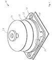
- FIG. 1 shows a schematic perspective view of an elastomeric membrane element 2 for a membrane valve.
- the elastomeric membrane element 2 comprises a working section 4, which is arranged within a fastening section 6.
- the working section 4 comprises a fastening means 8 in order to connect the working section 4 to a pressure piece and to move it along an infeed axis 10 by means of the pressure piece.
- the fastening means 8 protrudes from a dry side 12 of the elastomer membrane element 2, which lies opposite a medium side 14, and comprises, for example, an external thread.
- the fastening section 6 comprises through openings 16A, 16B, 16C and 16D, through which further fastening means can be guided in order to tighten the elastomeric membrane element 2 in relation to a valve body of the membrane valve.
- the fastening section 6 surrounding the working section 4 is therefore designed to fix the elastomeric membrane element 2 relative to the valve body of the membrane valve.
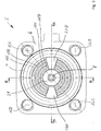
- Figure 2 shows a schematic plan view of the dry side 12 of the elastomeric membrane element 2.
- the fastening section 6 delimits the working section 4 in a ring shape.
- the working section 4 is constructed essentially rotationally symmetrically and comprises concentric expansion contours 18A, 18B, 18C and 18D on the dry side 12.
- the expansion contours 18A to 18D are arranged at least in sections as annular projections concentrically to one another and have a common center on the infeed axis 10.
- the concentric expansion contours 18A to 18D are provided by opposing, continuous and uninterrupted contact surfaces 20A and 20B for the application of a pressure piece of a valve drive of the Diaphragm valve interrupted.
- the fastening means 8 protrudes from a central thickening 21 on the dry side 12.
- At least one expansion contour for example as a rib that runs at least in sections, can be arranged on the dry side 12.
- This at least one expansion contour is preferably arranged where there are bends and loads in order to achieve a higher strength of the membrane against pressure and ultimately against crack formation while maintaining flexibility.
- FIG 3 shows a schematic sectional view of the elastomer membrane element 2 according to a section AA Figure 2 .
- the fastening section 6 comprises an at least partially vulcanized, rigid insert 22, which in the present case is designed in section as a continuous material, in particular made of metal.
- the rigid insert 22 can also be designed as a bent sheet.
- the rigid insert 22 is at least partially surrounded by an elastomer material.
- an annular recess 30 adjoins the fastening section 6 toward the infeed axis 10 and opens towards the medium side 14.
- a material taper 32 results in the area of the recess 30 between the fastening section 6 and the working section 4, a material taper 32 results.
- the working section 4 adjoins the material taper 32 with an annular elevation 34 towards the feed taper 32.
- the fastening means 8, which is arranged in the central thickening 21, comprises a diameter recess 36.
- the fastening means 8 is thus accommodated in the elastomer membrane element 2 at least in sections.
- a fabric insert 38 extends flat along a course of the working section 4 and is arranged towards the dry side 12 of the elastomeric membrane element 2. Furthermore, the fabric insert 38 extends into the diameter recess 36.
- Figure 4 shows an enlarged section of the sectional view Figure 3 in the area of the recess 30.
- a first contact surface 40 of the fastening section 6 is located on the medium side 14 of the elastomer membrane element 2.
- a second contact surface 42 likewise arranged on the medium side 14, adjoins the recess 30 towards the infeed axis 10 and is the same Assigned to section 4.
- An unassembled and relaxed state of the elastomeric membrane element 2 is shown. Because the first contact surface 40 springs back relative to the second contact surface 42, the contact surface 42 is pressed onto this flat contact surface when the two contact surfaces 40 and 42 lie on a flat contact surface of the valve body of the diaphragm valve at the same time.
- the recess 30 is therefore sealed off from a fluid-guided region of the working section 4 and no fluid can enter the recess 30.
- the material taper 32 is deformed in the region of the recess 30.
- the recess 30 essentially adjoins the rigid insert 22.
- a thin elastomer layer 44 separates the rigid insert 22 from the recess 30.
- the recess 30 tapers in the direction of the dry side 6. Starting from the opening of the recess 30, the recess 30 initially has a constant opening width and then tapers along a bevel 46 arranged radially inwards in the direction of the dry side 6. The bevel 46 merges into a curvature 48 which defines the smallest thickness of the material taper 32.
- the rigid insert 22 has an annular inner contour in the region of the elastomer layer 44, at least in sections, radially inward.
- Figure 5 shows a schematic sectional view of the elastomeric membrane element 2 according to a section BB from FIG Figure 2 ,
- the fabric insert 38 is not shown for reasons of clarity.
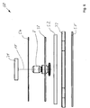
- Figure 6 shows a schematic side view of the individual components for the production of the elastomer membrane element 2 according to an arrangement 60.
- the components are partially provided with the same reference numerals as in the elastomer membrane element 2 produced in FIGS Figures 1 to 5 ,
- a base plate 50, an insert plate 52, an end plate 54 and thickening 21 are made, for example, of ethylene-propylene-diene rubber, EPDM.
- the fabric insert 38 is also shown.
- the fastening means 8 and the rigid insert 22 are preferably made of a metal.
- Figure 7 shows an exploded perspective view of the arrangement from Figure 6 without the fastening means 8. It is shown how the insert plate 52 can be fitted into the inner contour 54 of the rigid insert 22, which is at least partially circular.
- the arrangement 60 can be vulcanized with the additionally arranged fastening means 8, whereby the elastomeric membrane element 2 is produced.
Landscapes
- Engineering & Computer Science (AREA)
- General Engineering & Computer Science (AREA)
- Mechanical Engineering (AREA)
- Diaphragms And Bellows (AREA)
- Reciprocating Pumps (AREA)
Description
Die Erfindung betrifft ein Elastomer-Membranelement nach dem Oberbegriff des Anspruchs 1.The invention relates to an elastomeric membrane element according to the preamble of claim 1.
Elastomer-Membranelemente sind allgemein bekannt. Insbesondere sind Membrane bekannt, die an einem Rand zwischen zwei Ventilgehäuseteilen fest eingespannt werden. Auch sind Metalleinlagen innerhalb eines Einspannrandes der Membran bekannt. Beispielhaft wird auf die
Des Weiteren ist bekannt, dass beim Verpressen der Membrane und dem Steg Materialanhäufungen zur Faltenbildung führen können, welche die Lebensdauer des Elastomer-Membranelements beeinflussen.Furthermore, it is known that when the membrane and the web are pressed together, material accumulations can lead to the formation of folds, which influence the service life of the elastomer membrane element.
Mithin ist es Aufgabe der Erfindung, ein Elastomer-Membranelement dahingehend weiterzubilden, dass eine sichere Funktion des Elastomer-Membranelements gewährleistet werden kann.It is therefore an object of the invention to further develop an elastomer membrane element in such a way that reliable functioning of the elastomer membrane element can be ensured.
Die der Erfindung zugrunde liegende Aufgabe wird durch ein Elastomer-Membranelement nach dem Anspruch 1 gelöst. Vorteilhafte Weiterbildungen sind in den Unteransprüchen angegeben. Für die Erfindung wichtige Merkmale finden sich ferner in der nachfolgenden Beschreibung und in der Zeichnung, wobei die Merkmale sowohl in Alleinstellung als auch in unterschiedlichen Kombinationen für die Erfindung wichtig sein können, ohne dass hierauf nochmals explizit hingewiesen wird.The object underlying the invention is achieved by an elastomeric membrane element according to claim 1. Advantageous further developments are specified in the subclaims. Features important for the invention can also be found in the following description and in the drawing, the features being important both alone and in different combinations for the invention, without being explicitly mentioned again.
Es wird ein Elastomer-Membranelement für ein Membranventil vorgeschlagen, wobei das Elastomer-Membranelement einen Arbeitsabschnitt zum Öffnen und Schließen eines Fluidkanals des Membranventils umfasst, und wobei das Elastomer-Membranelement einen den Arbeitsabschnitt umgebenden Befestigungsabschnitt zur Festlegung des Elastomer-Membranelements gegenüber einem Ventilkörper des Membranventils umfasst. Zwischen dem Arbeitsabschnitt und dem Befestigungsabschnitt ist zumindest abschnittsweise eine Ausnehmung angeordnet, wodurch es ermöglicht wird, dass während des Betriebs des Elastomer-Membranelements Restverformungen aus dem Arbeitsabschnitt in die Ausnehmung hinein fließen können, ohne dass dadurch die Funktion des Arbeitsabschnitts beeinträchtigt wird. Insbesondere auf der Mediumseite des Elastomer-Membranelements kann durch ein Abfließen des Elastomer-Materials in die Ausnehmung hinein verhindert werden, dass das Schließen des Fluidkanals durch eine Verformung des Arbeitsabschnitts auf der Mediumseite beeinträchtigt wird. Auf einer Trockenseite kann durch das mögliche Abfließen des Elastomer-Materials in die Ausnehmung hinein die Wahrscheinlichkeit einer Faltenbildung reduziert werden.An elastomer membrane element for a membrane valve is proposed, the elastomer membrane element comprising a working section for opening and closing a fluid channel of the membrane valve, and wherein the elastomer membrane element has a fastening section surrounding the working section for fixing the elastomer membrane element to a valve body of the membrane valve includes. A recess is arranged at least in sections between the working section and the fastening section, which makes it possible for residual deformations to flow from the working section into the recess during operation of the elastomeric membrane element, without the function of the working section being impaired thereby. In particular on the medium side of the elastomer membrane element, the elastomer material flowing into the recess can prevent the closing of the fluid channel from being impaired by deformation of the working section on the medium side. On a dry side, the possibility of the elastomer material flowing into the recess can reduce the likelihood of wrinkling.
In einer vorteilhaften Ausführungsform springt eine erste Anlagefläche des Befestigungsabschnitts auf der Mediumseite in einem nicht montierten Zustand des Elastomer-Membranelements gegenüber einer zweiten Anlagefläche, welche sich auf der Mediumseite radial nach innen an die Ausnehmung anschließt, zurück. Bei der Montage des Elastomer-Membranelements mittels des Befestigungsabschnitts wird die erste Anlagefläche an eine ebene Anlagefläche eines Ventilstücks gedrückt. Hierdurch wird eine Materialverjüngung im Bereich der Ausnehmung durch die gegenüber der ersten Anlagefläche vorspringende zweite Anlagefläche unter Zug gesetzt, wodurch die zweite Anlagefläche durch Anliegen an der Anlagefläche des Ventilstücks die Ausnehmung zum Medium führenden Bereich des Arbeitsabschnitts hin abdichtet.In an advantageous embodiment, a first contact surface of the fastening section on the medium side springs back in an unmounted state of the elastomer membrane element compared to a second contact surface which adjoins the recess radially inwards on the medium side. When the elastomeric membrane element is installed by means of the fastening section, the first contact surface is pressed against a flat contact surface of a valve piece. This results in a material taper in the region of the recess by the protruding one in relation to the first contact surface second contact surface is placed under tension, whereby the second contact surface seals the recess to the medium-leading region of the working section by contacting the contact surface of the valve piece.
Die Ausnehmung öffnet sich hin zur Mediumseite des Membranelements. Hierdurch wird die Ausnehmung gegenüber Beeinflussungen von der Trockenseite herrührend geschützt.The recess opens towards the medium side of the membrane element. As a result, the recess is protected against influences from the dry side.
In einer vorteilhaften Ausführungsform ist die Ausnehmung radial außerhalb eines mediengeführten Bereichs angeordnet. Es kann vorteilhaft erreicht werden, dass die Ausnehmung einen Aufnahmebereich für verfließende Materialanhäufungen bzw. Restverformungen des Elastomer-Materials bildet und nicht durch einen Fluiddruck oder eine Membranbewegung unmittelbar beeinflusst wird.In an advantageous embodiment, the recess is arranged radially outside of a media-guided area. It can advantageously be achieved that the recess forms a receiving area for flowing material accumulations or residual deformations of the elastomer material and is not directly influenced by a fluid pressure or a membrane movement.
In einer vorteilhaften Ausführungsform ist die Ausnehmung zumindest abschnittsweise kreisringförmig ausgebildet. Hierdurch wird es ermöglicht, einen im Wesentlichen rotationssymmetrisch ausgebildeten Arbeitsbereich zu schaffen. Der im Wesentlichen rotationssymmetrisch ausgebildete Arbeitsbereich ist in und entgegen einer Zustellrichtung leicht verformbar, wodurch ein Ventilantrieb schwächer ausgebildet sein kann.In an advantageous embodiment, the recess is annular, at least in sections. This makes it possible to create an essentially rotationally symmetrical working area. The essentially rotationally symmetrical working area can be easily deformed in and against an infeed direction, as a result of which a valve drive can be made weaker.
Der Befestigungsabschnitt umfasst eine im Wesentlichen starre Einlage. Die Ausnehmung schließt sich radial nach innen an die starre Einlage an. So werden zum einen mögliche Materialverformungen im Befestigungsabschnitt verringert und zum anderen Materialverformungen insbesondere ein Verfließen des Elastomer-Materials im Bereich des Arbeitsabschnitts erlaubt. Des Weiteren ermöglicht die starre Einlage Freiheitsgrade bei der Anordnung und Ausführung des Befestigungsabschnitts.The fastening section comprises an essentially rigid insert. The recess adjoins the rigid insert radially inwards. Thus, on the one hand, possible material deformations in the fastening section are reduced and, on the other hand, material deformation, in particular, a flow of the elastomer material in the area of the Working section allowed. Furthermore, the rigid insert enables degrees of freedom in the arrangement and execution of the fastening section.
Die starre Einlage weist zumindest abschnittsweise eine ringförmige Innenkontur auf. Hierdurch wird die Basis für die rotationssymmetrische Ausführung des Arbeitsabschnitts geschaffen. Die rotationssymmetrische Ausführung ermöglicht eine radial gleichmäßige Kräfteverteilung innerhalb des Arbeitsabschnitts. Darüber hinaus wird der fluidführende Bereich des Elastomer-Membranelements ringförmig nach außen abgedichtet.The rigid insert has an annular inner contour, at least in sections. This creates the basis for the rotationally symmetrical execution of the working section. The rotationally symmetrical design enables a radially even distribution of forces within the working section. In addition, the fluid-carrying area of the elastomeric membrane element is sealed to the outside in a ring.
In einer vorteilhaften Ausführungsform umfasst der Arbeitsabschnitt eine Gewebeeinlage, wobei die Gewebeeinlage innerhalb des Arbeitsabschnitts hin zu einer Trockenseite des Elastomer-Membranelements angeordnet ist. Hierdurch wird das Elastomer-Membranelement hin zur Trockenseite stabilisiert. Insbesondere Dehnungskonturen wie beispielsweise Verstärkungsrippen auf der Trockenseite können durch die Gewebeeinlage stabilisiert werden.In an advantageous embodiment, the working section comprises a fabric insert, the fabric insert being arranged within the working section towards a dry side of the elastomer membrane element. This stabilizes the elastomer membrane element towards the dry side. In particular, stretch contours such as reinforcing ribs on the dry side can be stabilized by the fabric insert.
In einer vorteilhaften Ausführungsform ragt ein Befestigungsmittel für ein Druckstück eines Ventilantriebs auf der Trockenseite des Membranelements von dem Arbeitsabschnitt ab, wobei das Befestigungsmittel abschnittsweise in dem Elastomer-Membranelement aufgenommen ist, und wobei die Gewebeeinlage in einen Durchmesserrücksprung des Befestigungsmittels hineinragt. Auch bei nicht unmittelbarer Befestigung der Gewebeeinlage an dem Befestigungsmittel wird insbesondere bei Bewegungen des Arbeitsabschnitts entgegen der Zustellrichtung eine Kraftübertragung vom Befestigungsmittel in den Arbeitsbereich hinein durch die Gewebeeinlage unterstützt.In an advantageous embodiment, a fastening means for a pressure piece of a valve drive protrudes from the working section on the dry side of the membrane element, the fastening means being received in sections in the elastomer membrane element, and the fabric insert protruding into a recess in the diameter of the fastening means. Even if the tissue insert is not directly attached to the fastening means, a becomes particularly in the case of movements of the working section against the infeed direction Power transmission from the fastener into the work area supported by the fabric insert.
In einer vorteilhaften Ausführungsform umfasst die Trockenseite des Arbeitsabschnitts konzentrische Dehnungskonturen. Hierdurch wird eine Faltenbildung bei der Bewegung des Arbeitsabschnitts verringert und gleichzeitig die Stabilität des Elastomer-Membranelements verbessert. Insbesondere kann eine Dicke der Membran durch das Vorsehen der konzentrischen Dehnungskonturen reduziert werden, was sich vorteilhaft auf die Bewegbarkeit entlang der Zustellachse auswirkt. Mithin ist weniger Kraftaufwand zur Bewegung des Arbeitsbereichs entlang der Zustellachse nötig und ein Ventilantrieb kann schwächer ausgelegt werden.In an advantageous embodiment, the dry side of the working section comprises concentric expansion contours. This reduces wrinkling during the movement of the working section and at the same time improves the stability of the elastomer membrane element. In particular, a thickness of the membrane can be reduced by providing the concentric expansion contours, which has an advantageous effect on the mobility along the feed axis. As a result, less effort is required to move the work area along the infeed axis and a valve drive can be designed to be weaker.
In einer vorteilhaften Weiterbildung sind die konzentrischen Dehnungskonturen durch Anlageflächen für ein Druckstück eines Ventilantriebs des Membranventils unterbrochen. Durch die Anlageflächen wird die Kraftübertragung vom Druckstück auf das Elastomer-Membranelement ermöglicht und gleichzeitig wird durch die konzentrischen Dehnungskonturen eine Faltenbildung verringert.In an advantageous development, the concentric expansion contours are interrupted by contact surfaces for a pressure piece of a valve drive of the diaphragm valve. The contact surfaces enable the force transmission from the pressure piece to the elastomer membrane element and at the same time the formation of folds is reduced by the concentric expansion contours.
Weitere Merkmale und Vorteile der Erfindung ergeben sich aus der nachfolgenden Beschreibung von Ausführungsbeispielen. Für funktionsäquivalente Merkmale und Größen werden allen Figuren die gleichen Bezugszeichen verwendet, ohne dass nochmals darauf hingewiesen wird. In der Zeichnung zeigen:
- Figur 1
- in einer schematischen perspektivischen Ansicht ein Elastomer-Membranelement für ein Membranventil;
Figur 2- eine schematische Draufsicht auf eine Trockenseite des Elastomer-Membranelements;
- Figuren 3 und 5
- jeweils eine schematische Schnittansicht des Elastomer-Membranelements;
Figur 4- einen vergrößerten Ausschnitt der Schnittansicht aus
Figur 3 im Bereich einer Ausnehmung; Figur 6- eine schematische Seitenansicht der einzelnen Komponenten zur Herstellung des Elastomer-Membranelements; und
- Figur 7
- eine perspektivische Explosionsansicht der Anordnung aus
Figur 6 .
- Figure 1
- a schematic perspective view of an elastomeric membrane element for a membrane valve;
- Figure 2
- is a schematic plan view of a dry side of the elastomeric membrane element;
- Figures 3 and 5
- each a schematic sectional view of the elastomeric membrane element;
- Figure 4
- an enlarged section of the sectional view
Figure 3 in the area of a recess; - Figure 6
- is a schematic side view of the individual components for the production of the elastomer membrane element; and
- Figure 7
- an exploded perspective view of the arrangement
Figure 6 ,
Der Befestigungsabschnitt 6 umfasst Durchgangsöffnungen 16A, 16B, 16C und 16D, durch welche weitere Befestigungsmittel führbar sind, um das Elastomer-Membranelement 2 gegenüber einem Ventilkörper des Membranventils auf Block anzuziehen. Mithin ist der den Arbeitsabschnitt 4 umgebende Befestigungsabschnitt 6 zur Festlegung des Elastomer-Membranelements 2 gegenüber dem Ventilkörper des Membranventils ausgebildet.The
In einer nicht gezeigten Ausführungsform kann zumindest eine Dehnungskontur, beispielsweise als zumindest abschnittsweise umlaufende Rippe, auf der Trockenseite 12 angeordnet sein. Diese zumindest eine Dehnungskontur ist bevorzugt dort angeordnet, wo Biegungen und Belastungen auftreten, um eine höhere Festigkeit der Membrane gegen Druck und letztendlich gegen eine Rissbildung bei Beibehaltung der Flexibilität zu erreichen.In an embodiment not shown, at least one expansion contour, for example as a rib that runs at least in sections, can be arranged on the
Die starre Einlage 22 ist zumindest teilweise von einem Elastomer-Material umgeben. Auf der Mediumseite 14 des Elastomer-Membranelements 2 schließt sich zur Zustellachse 10 hin eine kreisringförmige Ausnehmung 30 an den Befestigungsabschnitt 6 an, welche sich hin zu der Mediumseite 14 öffnet. Entsprechend ergibt sich im Bereich der Ausnehmung 30 zwischen dem Befestigungsabschnitt 6 und dem Arbeitsabschnitt 4 eine Materialverjüngung 32. Hin zur Zustellachse 10 schließt sich an die Materialverjüngung 32 der Arbeitsabschnitt 4 mit einer kreisringförmigen Erhebung 34 an.The
Das Befestigungsmittel 8, welches in der zentralen Verdickung 21 angeordnet ist, umfasst einen Durchmesserrücksprung 36. Das Befestigungsmittel 8 ist somit zumindest abschnittsweise in dem Elastomer-Membranelement 2 aufgenommen. Eine Gewebeeinlage 38 erstreckt sich flächig entlang eines Verlaufs des Arbeitsabschnitts 4 und ist hin zur Trockenseite 12 des Elastomer-Membranelements 2 angeordnet. Des Weiteren erstreckt sich die Gewebeeinlage 38 in den Durchmesserrücksprung 36 hinein.The fastening means 8, which is arranged in the
Die Ausnehmung 30 schließt sich im Wesentlichen unmittelbar an die starre Einlage 22 an. Eine dünne Elastomer-Schicht 44 trennt die starre Einlage 22 von der Ausnehmung 30. Des Weiteren verjüngt sich die Ausnehmung 30 in Richtung der Trockenseite 6. Ausgehend von der Öffnung der Ausnehmung 30 weist die Ausnehmung 30 zunächst eine konstante Öffnungsweite auf und verjüngt sich anschließend entlang einer radial nach innen angeordneten Schräge 46 in Richtung der Trockenseite 6. Die Schräge 46 geht in eine Wölbung 48 über, welche die geringste Dicke der Materialverjüngung 32 definiert. Des Weiteren weist die starre Einlage 22 radial nach innen zumindest abschnittsweise eine ringförmige Innenkontur im Bereich der Elastomer-Schicht 44 auf.The
Claims (9)
- An elastomer membrane element (2) for a membrane valve, the elastomer membrane element (2) comprising a work portion (4) for opening and closing a fluid channel of the membrane valve, the elastomer membrane element (2) comprising a fastening portion (6) surrounding the work portion (4) for securing the elastomer membrane element (2) with respect to a valve body of the membrane valve, a recess (30) being arranged at least in portions between the work portion (4) and the fastening portion (6), which recess opens toward a medium side (14) of the elastomer membrane element (2), and the fastening portion (6) comprising a rigid insert (22) which has an annular inner contour (54) at least in portions, characterized in that the recess (30) radially inwardly directly adjoins the rigid insert (22).
- The elastomer membrane element (2) according to claim 1, wherein, in a non-assembled state of the elastomer membrane element (2), a first abutment surface (40) of the fastening portion (6) on the medium side (14) springs back against a second abutment surface (42), which on the medium side (14) radially inwardly adjoins the recess (30) .
- The elastomer membrane element (2) according to any of the preceding claims, wherein the recess (30) is arranged radially outside of a media-guiding region.
- The elastomer membrane element (2) according to any of the preceding claims, wherein the recess (30) is ring-segment-shaped at least in portions.
- The elastomer membrane element (2) according to any of the preceding claims, wherein the work portion (4) comprises a fabric insert (38), and wherein the fabric insert (38) within the work portion (4) is arranged toward a dry side (12) of the elastomer membrane element (2).
- The elastomer membrane element (2) according to claim 5, wherein a fastening means (8) for a pressure piece of a valve drive on the dry side (12) of the elastomer membrane element (2) protrudes from the work portion (4), wherein the fastening means (8) is received in portions in the elastomer membrane element (2), and wherein the fabric insert (38) protrudes into a diametrical groove (36) in the fastening means (8).
- The elastomer membrane element (2) according to claim 5, wherein the dry side (12) of the work portion (4) comprises concentric expansion contours (18A-D).
- The elastomer membrane element (2) according to claim 7, wherein the concentric expansion contours (18A-D) are interrupted by abutment surfaces (20A, 20B) for a pressure piece of a valve drive of the membrane valve.
- A membrane valve comprising an elastomer membrane element (2) according to any of the preceding claims.
Applications Claiming Priority (1)
| Application Number | Priority Date | Filing Date | Title |
|---|---|---|---|
| DE102016101782.5A DE102016101782A1 (en) | 2016-02-02 | 2016-02-02 | Elastomeric membrane element |
Publications (2)
| Publication Number | Publication Date |
|---|---|
| EP3203124A1 EP3203124A1 (en) | 2017-08-09 |
| EP3203124B1 true EP3203124B1 (en) | 2020-02-26 |
Family
ID=57714517
Family Applications (1)
| Application Number | Title | Priority Date | Filing Date |
|---|---|---|---|
| EP17150162.0A Active EP3203124B1 (en) | 2016-02-02 | 2017-01-03 | Elastomer membrane element |
Country Status (2)
| Country | Link |
|---|---|
| EP (1) | EP3203124B1 (en) |
| DE (1) | DE102016101782A1 (en) |
Families Citing this family (5)
| Publication number | Priority date | Publication date | Assignee | Title |
|---|---|---|---|---|
| KR101923169B1 (en) * | 2017-10-20 | 2019-02-27 | 에프디씨 주식회사 | A rupture disc assembly for vehicle |
| DE102017128229A1 (en) * | 2017-11-29 | 2019-05-29 | Bürkert Werke GmbH & Co. KG | Membrane assembly for a diaphragm valve and diaphragm valve |
| DE102017128996A1 (en) * | 2017-12-06 | 2019-06-06 | Gemü Gebr. Müller Apparatebau Gmbh & Co. Kommanditgesellschaft | Membrane for a diaphragm valve |
| EP3604873B1 (en) * | 2018-08-03 | 2021-06-02 | SISTO Armaturen S.A. | Membrane with flap |
| DE102020130652A1 (en) | 2020-11-19 | 2022-05-19 | Gemü Gebr. Müller Apparatebau Gmbh & Co. Kommanditgesellschaft | Diaphragm for a diaphragm valve, multi-piece diaphragm, diaphragm valve, method of assembly |
Family Cites Families (8)
| Publication number | Priority date | Publication date | Assignee | Title |
|---|---|---|---|---|
| ZA704303B (en) * | 1969-07-04 | 1971-03-31 | Saunders Valve Co Ltd | Flow control valves |
| DE2307580A1 (en) | 1973-02-16 | 1974-09-05 | Klein Schanzlin & Becker Ag | DIAPHRAGM VALVE |
| US6079692A (en) * | 1997-04-03 | 2000-06-27 | Hunter Innovations | Combination diaphragm and groove coupler seal for automatic control valves |
| GB2399616A (en) * | 2003-03-19 | 2004-09-22 | Crane Process Flow Technologie | Diaphragm valves and diaphragms therefor |
| DE202005001250U1 (en) * | 2005-01-26 | 2006-06-08 | GEMÜ Gebr. Müller Apparatebau GmbH & Co. KG | Diaphragm for diaphragm valve |
| US8357123B2 (en) * | 2007-09-17 | 2013-01-22 | Covidien Lp | Surgical portal with gel and fabric seal assembly |
| WO2011049705A1 (en) * | 2009-10-19 | 2011-04-28 | Parker-Hannifin Corporation | Seal assembly |
| DE102014210353A1 (en) * | 2014-06-02 | 2015-12-03 | Gemü Gebr. Müller Apparatebau Gmbh & Co. Kommanditgesellschaft | Adapter for a shut-off device |
-
2016
- 2016-02-02 DE DE102016101782.5A patent/DE102016101782A1/en not_active Withdrawn
-
2017
- 2017-01-03 EP EP17150162.0A patent/EP3203124B1/en active Active
Non-Patent Citations (1)
| Title |
|---|
| None * |
Also Published As
| Publication number | Publication date |
|---|---|
| DE102016101782A1 (en) | 2017-08-03 |
| EP3203124A1 (en) | 2017-08-09 |
Similar Documents
| Publication | Publication Date | Title |
|---|---|---|
| EP3203124B1 (en) | Elastomer membrane element | |
| EP1456574B1 (en) | Connection piece for fluid lines and device embodied thereas | |
| EP1686298B1 (en) | Diaphragm for diaphragm valve | |
| DE2445106A1 (en) | THROTTLE FLAP VALVE | |
| WO2009059841A1 (en) | Guide ring for a piston pump, and piston pump | |
| DE202010000254U1 (en) | tire valve | |
| DE3045215A1 (en) | FLAP | |
| DE4402079B4 (en) | Rotary obturator | |
| DE2644518A1 (en) | HIGH TEMPERATURE RESISTANT BIDIRETIONAL METAL SEAL | |
| DE2634153A1 (en) | VALVE | |
| DE102013215294A1 (en) | Membrane arrangement for a valve device | |
| EP3246605B1 (en) | Membrane valve | |
| DE102019120225A1 (en) | Valve and device for regulating pressures of a fluid with the valve and device for securing the valve in the transmission component | |
| EP3844375B1 (en) | Valve | |
| EP3495702B1 (en) | Membrane for a diaphragm valve | |
| EP3730822B1 (en) | Seal assembly and fluid valve | |
| WO2020052858A1 (en) | Connection device for pipes with leakage indicator | |
| EP2833043A1 (en) | Valve device | |
| DE102010027879B4 (en) | Connection unit for connecting a fluid line to a waterbed mattress | |
| DE3123028C2 (en) | Diaphragm valve | |
| EP3092430B1 (en) | Valve mechanism for controlling a fluid, in particular an abrasive high-viscosity material | |
| EP4059631A1 (en) | Gripping device | |
| DE102007041950B4 (en) | Valve arrangement for a hydrostatic piston engine | |
| DE102019133667A1 (en) | Device for regulating pressures of a fluid with a valve | |
| EP3070384B1 (en) | Valve |
Legal Events
| Date | Code | Title | Description |
|---|---|---|---|
| PUAI | Public reference made under article 153(3) epc to a published international application that has entered the european phase |
Free format text: ORIGINAL CODE: 0009012 |
|
| STAA | Information on the status of an ep patent application or granted ep patent |
Free format text: STATUS: THE APPLICATION HAS BEEN PUBLISHED |
|
| AK | Designated contracting states |
Kind code of ref document: A1 Designated state(s): AL AT BE BG CH CY CZ DE DK EE ES FI FR GB GR HR HU IE IS IT LI LT LU LV MC MK MT NL NO PL PT RO RS SE SI SK SM TR |
|
| AX | Request for extension of the european patent |
Extension state: BA ME |
|
| STAA | Information on the status of an ep patent application or granted ep patent |
Free format text: STATUS: REQUEST FOR EXAMINATION WAS MADE |
|
| 17P | Request for examination filed |
Effective date: 20180112 |
|
| RBV | Designated contracting states (corrected) |
Designated state(s): AL AT BE BG CH CY CZ DE DK EE ES FI FR GB GR HR HU IE IS IT LI LT LU LV MC MK MT NL NO PL PT RO RS SE SI SK SM TR |
|
| STAA | Information on the status of an ep patent application or granted ep patent |
Free format text: STATUS: EXAMINATION IS IN PROGRESS |
|
| 17Q | First examination report despatched |
Effective date: 20180710 |
|
| GRAP | Despatch of communication of intention to grant a patent |
Free format text: ORIGINAL CODE: EPIDOSNIGR1 |
|
| STAA | Information on the status of an ep patent application or granted ep patent |
Free format text: STATUS: GRANT OF PATENT IS INTENDED |
|
| INTG | Intention to grant announced |
Effective date: 20190905 |
|
| RIN1 | Information on inventor provided before grant (corrected) |
Inventor name: MUELLER, FRITZ Inventor name: MAYER, PETER Inventor name: OETTINGER, NICOLE |
|
| GRAS | Grant fee paid |
Free format text: ORIGINAL CODE: EPIDOSNIGR3 |
|
| GRAA | (expected) grant |
Free format text: ORIGINAL CODE: 0009210 |
|
| STAA | Information on the status of an ep patent application or granted ep patent |
Free format text: STATUS: THE PATENT HAS BEEN GRANTED |
|
| RAP1 | Party data changed (applicant data changed or rights of an application transferred) |
Owner name: GEMUE GEBR. MUELLER APPARATEBAU GMBH & CO. KOMMANDITGESELLSCHAFT |
|
| AK | Designated contracting states |
Kind code of ref document: B1 Designated state(s): AL AT BE BG CH CY CZ DE DK EE ES FI FR GB GR HR HU IE IS IT LI LT LU LV MC MK MT NL NO PL PT RO RS SE SI SK SM TR |
|
| REG | Reference to a national code |
Ref country code: GB Ref legal event code: FG4D Free format text: NOT ENGLISH |
|
| REG | Reference to a national code |
Ref country code: CH Ref legal event code: EP |
|
| REG | Reference to a national code |
Ref country code: AT Ref legal event code: REF Ref document number: 1238035 Country of ref document: AT Kind code of ref document: T Effective date: 20200315 |
|
| REG | Reference to a national code |
Ref country code: IE Ref legal event code: FG4D Free format text: LANGUAGE OF EP DOCUMENT: GERMAN |
|
| REG | Reference to a national code |
Ref country code: DE Ref legal event code: R096 Ref document number: 502017003924 Country of ref document: DE |
|
| PG25 | Lapsed in a contracting state [announced via postgrant information from national office to epo] |
Ref country code: NO Free format text: LAPSE BECAUSE OF FAILURE TO SUBMIT A TRANSLATION OF THE DESCRIPTION OR TO PAY THE FEE WITHIN THE PRESCRIBED TIME-LIMIT Effective date: 20200526 Ref country code: FI Free format text: LAPSE BECAUSE OF FAILURE TO SUBMIT A TRANSLATION OF THE DESCRIPTION OR TO PAY THE FEE WITHIN THE PRESCRIBED TIME-LIMIT Effective date: 20200226 Ref country code: RS Free format text: LAPSE BECAUSE OF FAILURE TO SUBMIT A TRANSLATION OF THE DESCRIPTION OR TO PAY THE FEE WITHIN THE PRESCRIBED TIME-LIMIT Effective date: 20200226 |
|
| REG | Reference to a national code |
Ref country code: NL Ref legal event code: MP Effective date: 20200226 |
|
| REG | Reference to a national code |
Ref country code: LT Ref legal event code: MG4D |
|
| PG25 | Lapsed in a contracting state [announced via postgrant information from national office to epo] |
Ref country code: HR Free format text: LAPSE BECAUSE OF FAILURE TO SUBMIT A TRANSLATION OF THE DESCRIPTION OR TO PAY THE FEE WITHIN THE PRESCRIBED TIME-LIMIT Effective date: 20200226 Ref country code: SE Free format text: LAPSE BECAUSE OF FAILURE TO SUBMIT A TRANSLATION OF THE DESCRIPTION OR TO PAY THE FEE WITHIN THE PRESCRIBED TIME-LIMIT Effective date: 20200226 Ref country code: LV Free format text: LAPSE BECAUSE OF FAILURE TO SUBMIT A TRANSLATION OF THE DESCRIPTION OR TO PAY THE FEE WITHIN THE PRESCRIBED TIME-LIMIT Effective date: 20200226 Ref country code: BG Free format text: LAPSE BECAUSE OF FAILURE TO SUBMIT A TRANSLATION OF THE DESCRIPTION OR TO PAY THE FEE WITHIN THE PRESCRIBED TIME-LIMIT Effective date: 20200526 Ref country code: GR Free format text: LAPSE BECAUSE OF FAILURE TO SUBMIT A TRANSLATION OF THE DESCRIPTION OR TO PAY THE FEE WITHIN THE PRESCRIBED TIME-LIMIT Effective date: 20200527 Ref country code: IS Free format text: LAPSE BECAUSE OF FAILURE TO SUBMIT A TRANSLATION OF THE DESCRIPTION OR TO PAY THE FEE WITHIN THE PRESCRIBED TIME-LIMIT Effective date: 20200626 |
|
| PG25 | Lapsed in a contracting state [announced via postgrant information from national office to epo] |
Ref country code: NL Free format text: LAPSE BECAUSE OF FAILURE TO SUBMIT A TRANSLATION OF THE DESCRIPTION OR TO PAY THE FEE WITHIN THE PRESCRIBED TIME-LIMIT Effective date: 20200226 |
|
| PG25 | Lapsed in a contracting state [announced via postgrant information from national office to epo] |
Ref country code: SM Free format text: LAPSE BECAUSE OF FAILURE TO SUBMIT A TRANSLATION OF THE DESCRIPTION OR TO PAY THE FEE WITHIN THE PRESCRIBED TIME-LIMIT Effective date: 20200226 Ref country code: EE Free format text: LAPSE BECAUSE OF FAILURE TO SUBMIT A TRANSLATION OF THE DESCRIPTION OR TO PAY THE FEE WITHIN THE PRESCRIBED TIME-LIMIT Effective date: 20200226 Ref country code: RO Free format text: LAPSE BECAUSE OF FAILURE TO SUBMIT A TRANSLATION OF THE DESCRIPTION OR TO PAY THE FEE WITHIN THE PRESCRIBED TIME-LIMIT Effective date: 20200226 Ref country code: CZ Free format text: LAPSE BECAUSE OF FAILURE TO SUBMIT A TRANSLATION OF THE DESCRIPTION OR TO PAY THE FEE WITHIN THE PRESCRIBED TIME-LIMIT Effective date: 20200226 Ref country code: SK Free format text: LAPSE BECAUSE OF FAILURE TO SUBMIT A TRANSLATION OF THE DESCRIPTION OR TO PAY THE FEE WITHIN THE PRESCRIBED TIME-LIMIT Effective date: 20200226 Ref country code: LT Free format text: LAPSE BECAUSE OF FAILURE TO SUBMIT A TRANSLATION OF THE DESCRIPTION OR TO PAY THE FEE WITHIN THE PRESCRIBED TIME-LIMIT Effective date: 20200226 Ref country code: ES Free format text: LAPSE BECAUSE OF FAILURE TO SUBMIT A TRANSLATION OF THE DESCRIPTION OR TO PAY THE FEE WITHIN THE PRESCRIBED TIME-LIMIT Effective date: 20200226 Ref country code: PT Free format text: LAPSE BECAUSE OF FAILURE TO SUBMIT A TRANSLATION OF THE DESCRIPTION OR TO PAY THE FEE WITHIN THE PRESCRIBED TIME-LIMIT Effective date: 20200719 Ref country code: DK Free format text: LAPSE BECAUSE OF FAILURE TO SUBMIT A TRANSLATION OF THE DESCRIPTION OR TO PAY THE FEE WITHIN THE PRESCRIBED TIME-LIMIT Effective date: 20200226 |
|
| REG | Reference to a national code |
Ref country code: DE Ref legal event code: R097 Ref document number: 502017003924 Country of ref document: DE |
|
| PLBE | No opposition filed within time limit |
Free format text: ORIGINAL CODE: 0009261 |
|
| STAA | Information on the status of an ep patent application or granted ep patent |
Free format text: STATUS: NO OPPOSITION FILED WITHIN TIME LIMIT |
|
| PG25 | Lapsed in a contracting state [announced via postgrant information from national office to epo] |
Ref country code: IT Free format text: LAPSE BECAUSE OF FAILURE TO SUBMIT A TRANSLATION OF THE DESCRIPTION OR TO PAY THE FEE WITHIN THE PRESCRIBED TIME-LIMIT Effective date: 20200226 |
|
| 26N | No opposition filed |
Effective date: 20201127 |
|
| PG25 | Lapsed in a contracting state [announced via postgrant information from national office to epo] |
Ref country code: PL Free format text: LAPSE BECAUSE OF FAILURE TO SUBMIT A TRANSLATION OF THE DESCRIPTION OR TO PAY THE FEE WITHIN THE PRESCRIBED TIME-LIMIT Effective date: 20200226 Ref country code: SI Free format text: LAPSE BECAUSE OF FAILURE TO SUBMIT A TRANSLATION OF THE DESCRIPTION OR TO PAY THE FEE WITHIN THE PRESCRIBED TIME-LIMIT Effective date: 20200226 |
|
| PG25 | Lapsed in a contracting state [announced via postgrant information from national office to epo] |
Ref country code: MC Free format text: LAPSE BECAUSE OF FAILURE TO SUBMIT A TRANSLATION OF THE DESCRIPTION OR TO PAY THE FEE WITHIN THE PRESCRIBED TIME-LIMIT Effective date: 20200226 |
|
| REG | Reference to a national code |
Ref country code: CH Ref legal event code: PL |
|
| GBPC | Gb: european patent ceased through non-payment of renewal fee |
Effective date: 20210103 |
|
| PG25 | Lapsed in a contracting state [announced via postgrant information from national office to epo] |
Ref country code: LU Free format text: LAPSE BECAUSE OF NON-PAYMENT OF DUE FEES Effective date: 20210103 |
|
| REG | Reference to a national code |
Ref country code: BE Ref legal event code: MM Effective date: 20210131 |
|
| PG25 | Lapsed in a contracting state [announced via postgrant information from national office to epo] |
Ref country code: FR Free format text: LAPSE BECAUSE OF NON-PAYMENT OF DUE FEES Effective date: 20210131 |
|
| PG25 | Lapsed in a contracting state [announced via postgrant information from national office to epo] |
Ref country code: CH Free format text: LAPSE BECAUSE OF NON-PAYMENT OF DUE FEES Effective date: 20210131 Ref country code: GB Free format text: LAPSE BECAUSE OF NON-PAYMENT OF DUE FEES Effective date: 20210103 Ref country code: LI Free format text: LAPSE BECAUSE OF NON-PAYMENT OF DUE FEES Effective date: 20210131 |
|
| PG25 | Lapsed in a contracting state [announced via postgrant information from national office to epo] |
Ref country code: IE Free format text: LAPSE BECAUSE OF NON-PAYMENT OF DUE FEES Effective date: 20210103 |
|
| PG25 | Lapsed in a contracting state [announced via postgrant information from national office to epo] |
Ref country code: BE Free format text: LAPSE BECAUSE OF NON-PAYMENT OF DUE FEES Effective date: 20210131 |
|
| REG | Reference to a national code |
Ref country code: AT Ref legal event code: MM01 Ref document number: 1238035 Country of ref document: AT Kind code of ref document: T Effective date: 20220103 |
|
| PG25 | Lapsed in a contracting state [announced via postgrant information from national office to epo] |
Ref country code: AT Free format text: LAPSE BECAUSE OF NON-PAYMENT OF DUE FEES Effective date: 20220103 |
|
| PG25 | Lapsed in a contracting state [announced via postgrant information from national office to epo] |
Ref country code: HU Free format text: LAPSE BECAUSE OF FAILURE TO SUBMIT A TRANSLATION OF THE DESCRIPTION OR TO PAY THE FEE WITHIN THE PRESCRIBED TIME-LIMIT; INVALID AB INITIO Effective date: 20170103 |
|
| P01 | Opt-out of the competence of the unified patent court (upc) registered |
Effective date: 20230524 |
|
| PG25 | Lapsed in a contracting state [announced via postgrant information from national office to epo] |
Ref country code: CY Free format text: LAPSE BECAUSE OF FAILURE TO SUBMIT A TRANSLATION OF THE DESCRIPTION OR TO PAY THE FEE WITHIN THE PRESCRIBED TIME-LIMIT Effective date: 20200226 |
|
| PG25 | Lapsed in a contracting state [announced via postgrant information from national office to epo] |
Ref country code: MK Free format text: LAPSE BECAUSE OF FAILURE TO SUBMIT A TRANSLATION OF THE DESCRIPTION OR TO PAY THE FEE WITHIN THE PRESCRIBED TIME-LIMIT Effective date: 20200226 |
|
| PGFP | Annual fee paid to national office [announced via postgrant information from national office to epo] |
Ref country code: DE Payment date: 20240318 Year of fee payment: 8 |
|
| PG25 | Lapsed in a contracting state [announced via postgrant information from national office to epo] |
Ref country code: TR Free format text: LAPSE BECAUSE OF FAILURE TO SUBMIT A TRANSLATION OF THE DESCRIPTION OR TO PAY THE FEE WITHIN THE PRESCRIBED TIME-LIMIT Effective date: 20200226 |
|
| PG25 | Lapsed in a contracting state [announced via postgrant information from national office to epo] |
Ref country code: MT Free format text: LAPSE BECAUSE OF FAILURE TO SUBMIT A TRANSLATION OF THE DESCRIPTION OR TO PAY THE FEE WITHIN THE PRESCRIBED TIME-LIMIT Effective date: 20200226 |