EP3324070A1 - Spring, use of a plastic hose as a spring and fitting part for the interior of a vehicle - Google Patents
Spring, use of a plastic hose as a spring and fitting part for the interior of a vehicle Download PDFInfo
- Publication number
- EP3324070A1 EP3324070A1 EP17001869.1A EP17001869A EP3324070A1 EP 3324070 A1 EP3324070 A1 EP 3324070A1 EP 17001869 A EP17001869 A EP 17001869A EP 3324070 A1 EP3324070 A1 EP 3324070A1
- Authority
- EP
- European Patent Office
- Prior art keywords
- spring
- end portion
- filaments
- filament
- distance
- Prior art date
- Legal status (The legal status is an assumption and is not a legal conclusion. Google has not performed a legal analysis and makes no representation as to the accuracy of the status listed.)
- Granted
Links
- 230000006835 compression Effects 0.000 claims description 4
- 238000007906 compression Methods 0.000 claims description 4
- 239000004744 fabric Substances 0.000 description 3
- 239000002184 metal Substances 0.000 description 2
- 239000002131 composite material Substances 0.000 description 1
- 230000007423 decrease Effects 0.000 description 1
- 230000005489 elastic deformation Effects 0.000 description 1
- 230000002040 relaxant effect Effects 0.000 description 1
- 230000000284 resting effect Effects 0.000 description 1
- 239000004753 textile Substances 0.000 description 1
Images


Classifications
-
- F—MECHANICAL ENGINEERING; LIGHTING; HEATING; WEAPONS; BLASTING
- F16—ENGINEERING ELEMENTS AND UNITS; GENERAL MEASURES FOR PRODUCING AND MAINTAINING EFFECTIVE FUNCTIONING OF MACHINES OR INSTALLATIONS; THERMAL INSULATION IN GENERAL
- F16F—SPRINGS; SHOCK-ABSORBERS; MEANS FOR DAMPING VIBRATION
- F16F1/00—Springs
- F16F1/02—Springs made of steel or other material having low internal friction; Wound, torsion, leaf, cup, ring or the like springs, the material of the spring not being relevant
- F16F1/025—Springs made of steel or other material having low internal friction; Wound, torsion, leaf, cup, ring or the like springs, the material of the spring not being relevant characterised by having a particular shape
- F16F1/028—Springs made of steel or other material having low internal friction; Wound, torsion, leaf, cup, ring or the like springs, the material of the spring not being relevant characterised by having a particular shape cylindrical, with radial openings
-
- F—MECHANICAL ENGINEERING; LIGHTING; HEATING; WEAPONS; BLASTING
- F16—ENGINEERING ELEMENTS AND UNITS; GENERAL MEASURES FOR PRODUCING AND MAINTAINING EFFECTIVE FUNCTIONING OF MACHINES OR INSTALLATIONS; THERMAL INSULATION IN GENERAL
- F16F—SPRINGS; SHOCK-ABSORBERS; MEANS FOR DAMPING VIBRATION
- F16F1/00—Springs
- F16F1/36—Springs made of rubber or other material having high internal friction, e.g. thermoplastic elastomers
- F16F1/373—Springs made of rubber or other material having high internal friction, e.g. thermoplastic elastomers characterised by having a particular shape
- F16F1/3732—Springs made of rubber or other material having high internal friction, e.g. thermoplastic elastomers characterised by having a particular shape having an annular or the like shape, e.g. grommet-type resilient mountings
-
- B—PERFORMING OPERATIONS; TRANSPORTING
- B60—VEHICLES IN GENERAL
- B60N—SEATS SPECIALLY ADAPTED FOR VEHICLES; VEHICLE PASSENGER ACCOMMODATION NOT OTHERWISE PROVIDED FOR
- B60N2/00—Seats specially adapted for vehicles; Arrangement or mounting of seats in vehicles
- B60N2/80—Head-rests
- B60N2/806—Head-rests movable or adjustable
- B60N2/809—Head-rests movable or adjustable vertically slidable
- B60N2/812—Head-rests movable or adjustable vertically slidable characterised by their locking devices
- B60N2/815—Release mechanisms, e.g. buttons
-
- B—PERFORMING OPERATIONS; TRANSPORTING
- B60—VEHICLES IN GENERAL
- B60N—SEATS SPECIALLY ADAPTED FOR VEHICLES; VEHICLE PASSENGER ACCOMMODATION NOT OTHERWISE PROVIDED FOR
- B60N2/00—Seats specially adapted for vehicles; Arrangement or mounting of seats in vehicles
- B60N2/80—Head-rests
- B60N2/806—Head-rests movable or adjustable
- B60N2/838—Tiltable
- B60N2/841—Tiltable characterised by their locking devices
- B60N2/844—Release mechanisms, e.g. buttons
-
- F—MECHANICAL ENGINEERING; LIGHTING; HEATING; WEAPONS; BLASTING
- F16—ENGINEERING ELEMENTS AND UNITS; GENERAL MEASURES FOR PRODUCING AND MAINTAINING EFFECTIVE FUNCTIONING OF MACHINES OR INSTALLATIONS; THERMAL INSULATION IN GENERAL
- F16F—SPRINGS; SHOCK-ABSORBERS; MEANS FOR DAMPING VIBRATION
- F16F1/00—Springs
- F16F1/36—Springs made of rubber or other material having high internal friction, e.g. thermoplastic elastomers
- F16F1/362—Springs made of rubber or other material having high internal friction, e.g. thermoplastic elastomers made of steel wool, compressed hair, woven or non-woven textile, or like materials
-
- B—PERFORMING OPERATIONS; TRANSPORTING
- B60—VEHICLES IN GENERAL
- B60N—SEATS SPECIALLY ADAPTED FOR VEHICLES; VEHICLE PASSENGER ACCOMMODATION NOT OTHERWISE PROVIDED FOR
- B60N2/00—Seats specially adapted for vehicles; Arrangement or mounting of seats in vehicles
- B60N2/80—Head-rests
- B60N2002/899—Head-rests characterised by structural or mechanical details not otherwise provided for
-
- B—PERFORMING OPERATIONS; TRANSPORTING
- B60—VEHICLES IN GENERAL
- B60N—SEATS SPECIALLY ADAPTED FOR VEHICLES; VEHICLE PASSENGER ACCOMMODATION NOT OTHERWISE PROVIDED FOR
- B60N2205/00—General mechanical or structural details
- B60N2205/20—Measures for elimination or compensation of play or backlash
-
- F—MECHANICAL ENGINEERING; LIGHTING; HEATING; WEAPONS; BLASTING
- F16—ENGINEERING ELEMENTS AND UNITS; GENERAL MEASURES FOR PRODUCING AND MAINTAINING EFFECTIVE FUNCTIONING OF MACHINES OR INSTALLATIONS; THERMAL INSULATION IN GENERAL
- F16F—SPRINGS; SHOCK-ABSORBERS; MEANS FOR DAMPING VIBRATION
- F16F2234/00—Shape
- F16F2234/02—Shape cylindrical
Definitions
- the invention initially relates to a spring.
- Such a spring is for example from the DE 10 2006 026 029 A1 known.
- a locking device By means of a locking device, the headrest part of a headrest in different height position relative to the backrest of a vehicle seat can be locked and unlocked.
- a push button is provided, which is loaded by a spring element. When you press the button, the spring element is stretched so that restoring forces cause a return of the button in the starting position as soon as the button is not pressed.
- a device is provided, with which a headrest part can be locked in different height positions.
- the headrest has an actuating button, which is moved back to the starting position after actuation by a spring.
- springs are usually formed of metal springs. These have the disadvantage that, after actuation or by vibration, e.g. when driving on uneven ground, swing and cause unwanted whirring noises.
- the spring includes a first end portion and a second end portion.
- the first end region may e.g. with a first part in contact, while the second end region e.g. may be provided for attachment to a second part.
- the end regions In a relaxed first position of the spring, the end regions have a first distance and in at least one tensioned second position a second distance from one another.
- the spring is at least partially formed by a plastic.
- the spring is made entirely of plastic.
- the spring can z. B. be made by cutting a tubular endless fabric, both spring ends z. B. are sealed by staking and thus form a ring structure.
- the spring is e.g. formed tubular. That is, the spring comprises a wall formed as a hollow cylinder and an inner space within the wall. The tightness of the wall is not important. Here the spring characteristic of the wall is essential.
- the wall has e.g. at least one recess. The recesses may e.g. be formed between several filaments of the spring.
- the spring is e.g. designed as a compression spring or as a tension spring.
- the spring When removing or approaching the second end portion with respect to the first end portion, the spring is deformed against an elastic restoring force and thereby tightened. As the force on the spring decreases, the first end portion and the second end portion return to their original relative position, with the spring relaxing.
- the spring is eg compressible or extendable in the direction of a longitudinal axis. With this embodiment, a relatively large Travel ensured. When the spring is compressed, it can bulge, for example. If the spring is tubular, the spring may bulge radially during compression, for example. In an extension, the spring laces eg. A tubular spring constricts, for example, radially.
- the spring comprises at least one extending in the direction of the longitudinal axis of the spring filament.
- the filament is z. B. made of plastic.
- the spring comprises a plurality of filaments.
- the filaments extend e.g. from the first end portion of the spring to the second end portion.
- the filaments may but need not be parallel to a longitudinal axis of the spring.
- At least one filament forms an angle to a longitudinal axis of the spring.
- tissue means that the filaments have a special arrangement, so that they form a composite.
- Tissue means in the context of the invention but not that the filaments must be arranged at right angles to each other, such as warp and weft threads in a textile fabric.
- the fabric has e.g. a first type of filaments and at least a second type of filaments, wherein the first type of filaments are oriented differently relative to the second type of filaments.
- the second type of filament may e.g. make an angle with the first type of filament.
- the spring may form at least two layers of filaments.
- the first type of filaments and the second type of filaments are arranged, for example, in different layers.
- At a level Arrangement are, for example, the superimposed layers.
- the layers are arranged, for example, radially one behind the other.
- the spring may comprise at least two layers of a first type of filaments and / or a second type of filaments.
- the filament is e.g. connected at at least one end region with a ring structure.
- the filament is connected with a first end region having a first ring structure and with a second end region having a second ring structure.
- the individual filaments are e.g. connected with each other.
- the plastic tube includes a first end portion and a second end portion.
- the first end region and the second end region have a first distance in a relaxed first position of the plastic tube and a second distance from one another in at least one tensioned second position. In the second position, the plastic tubing is e.g. compressed or extended.
- the spring formed from plastic tube produces neither in the deformation nor in a vibration unwanted noise.
- the invention relates to an equipment part of a vehicle interior.
- a piece of equipment is eg a headrest.
- the actuator for actuating a lock comprised a spring.
- the fitting comprises first part and a second part relatively movable second part, the second part being adjustable between a first position and a second position.
- a spring loads the second part in the first position.
- the spring of the equipment part is inventively formed according to the first aspect of the invention.
- a headrest as a whole is denoted by the reference numeral 10 in the figures.
- the headrest 10 includes according to Fig. 1 a head part 11 and support rods 12, with which the head part 11 on the backrest of a vehicle seat, not shown, can be stored.
- a head bearing surface 13 is formed, which serves as an abutment for the head of a vehicle occupant.
- the head part 11 is movably mounted in the direction of z1 and z2 relative to the support rods.
- a locking device 16 see Fig. 3
- the head part 11 can be locked relative to the support rods 12 in different relative positions.
- an arrangement of a plurality of notches 40 is formed on the tag bars 12 (see Fig. 2 ).
- a latch associated with the head portion 11 is engaged with one of the notches so that movement of the head portion 11 into one the directions z1 or z2 or in both directions z1 and z2 is prevented.
- the head part 11 comprises according to Fig. 3 a slide 17 which can be moved in the direction y1 and y2.
- the slide 17 is assigned two latches, one latches each cooperating with one of the notches 40.
- the bolt In a release position of the locking device 16, the bolt is out of engagement with the notches and the head part 11 is movable in the direction z1 or z2.
- the locking device 16 can be adjusted by means of an actuating device 14 between the locking position and the release position.
- the actuating device 14 comprises an actuating element 15 with which a user can adjust the actuating device between a rest position and an actuating position by pressing on an actuating surface 28 of the actuating element 15 in the direction y1.
- the locking device 16 is adjustable to the release position by the actuator 15 is moved from a rest position in the direction of y1 in an actuated position.
- the adjusting element 15 is connected in movement with the slider 17.
- the actuator 15 automatically returns in the direction y2 in the rest position, which will be explained in more detail below.
- the actuator 14 is shown as an assembly.
- the actuating device 14 comprises a cup-shaped housing 18, which is fixedly attached to the head part 11. From the housing 18, the actuator 15 is guided in the movement between the rest position and the actuation position. An outer surface 19 of the adjusting element 15 slides along an inner surface 20 of the housing 18. A formed on the adjusting element 15, radially projecting hook 21 is guided in a recess 22 which is formed in the housing 18.
- the Recess 22 has the function of a backdrop to guide and limit the movement of the actuator 15.
- the actuator 15 is provided with a seat 23 and the housing 18 is provided with a seat 24.
- the seat 23 and the seat 24 face each other. Both seats 23 and 24 have the shape of a circular cylindrical projection.
- the first end portion 37 coaxially surrounds the seat 24 and is seated on the seat 24 such that an end surface of the end portion 37 abuts against a bottom surface 27.
- the second end portion 38 surrounds the seat 23 coaxially and is placed on the seat 23 so far that an end face of the end portion 38 abuts against a shoulder 26.
- the resting position is in Fig. 4 and the operating position is in Fig. 5 shown.
- a guide bar 25 can be seen, which limits the elastic deformation of the spring 36 to a certain area.
- the spring 36 is shown as a single part. It can be seen that the spring comprises 36 filaments 34 and 35.
- the filaments 34 form an angle ⁇ with the filaments 35 so that the filaments 34 and 35 intersect.
- the filaments 34 also form an angle ⁇ with the longitudinal axis m. That is, the filaments 34 and 35 are not arranged parallel to the longitudinal axis m.
- the spring 36 comprises three layers 31, 32 and 33, which are arranged radially one behind the other.
- An outer layer 31 is formed of the filaments 34, a middle layer 32 of the filaments 35 and an inner layer 33 of the filaments 34. All filaments 34 and 35 are fixedly connected at one end to a ring structure 29 of the first spring end 37 and at an opposite end to a ring structure 30 of the second spring end 38.
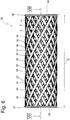
- Fig. 6 the spring is shown in the untensioned position.
- the untensioned position occupies the spring 36 in the rest position of the actuator.
- the spring 36 could already be subject to a slight bias in the rest position.
- the spring 36 In the rest position, the spring 36 has a length I1.
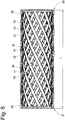
- Fig. 7 the spring is shown in the cocked position.
- the cocked position occupies the spring in the actuation position of the actuator 14.
- the spring 36 In the cocked position, the spring 36 has a length I2.
- the length I2 is smaller than the length I1, because the spring 36 is compressed in the present embodiment in the cocked position. Due to the compression, the spring 36 forms an annular, radially protruding curvature 39.
- Fig. 8 is a longitudinal sectional view through the spring 36 is shown.
- the spring 36 does not cause noise due to vibrations, such as e.g. in metal springs is the case.
Abstract
Die Erfindung betrifft eine Feder (36), insbesondere zur Bewegung wenigstens eines Teils einer Ausstattungs-Vorrichtung des Fahrzeug-Innenraums. Es war Aufgabe der Erfindung, eine Feder zu schaffen, bei welcher störende Geräusche aufgrund von Schwingungen nicht auftreten. Die Aufgabe wurde gelöst, indem die Feder aus Kunststoff gebildet ist.The invention relates to a spring (36), in particular for moving at least part of an equipment device of the vehicle interior. It was an object of the invention to provide a spring in which disturbing noises due to vibrations do not occur. The problem was solved by the spring is made of plastic.
Description
Die Erfindung betrifft zunächst eine Feder.The invention initially relates to a spring.
Eine solche Feder ist z.B. aus der
Auch in der
Derartige aus den vorbezeichneten Druckschriften bekannte Federn sind üblicherweise von Metallfedern gebildet. Diese haben den Nachteil, dass sie nach der Betätigung oder durch Erschütterung, z.B. bei einer Fahrt auf unebener Strecke, schwingen und dabei unerwünschte Surr-Geräusche verursachen.Such known from the aforementioned publications springs are usually formed of metal springs. These have the disadvantage that, after actuation or by vibration, e.g. when driving on uneven ground, swing and cause unwanted whirring noises.
Es war Aufgabe der Erfindung, eine Feder zu schaffen, bei welcher störende Geräusche aufgrund von Schwingungen nicht auftreten.It was an object of the invention to provide a spring in which disturbing noises due to vibrations do not occur.
Die Aufgabe wurde gemäß einem ersten Aspekt der Erfindung gelöst durch eine Feder mit den Merkmalen des Anspruchs 1.The object was achieved according to a first aspect of the invention by a spring having the features of
Die Feder umfasst einen ersten Endbereich und einen zweiten Endbereich. Der erste Endbereich kann z.B. mit einem ersten Teil in Kontakt stehen, während der zweite Endbereich z.B. zur Anlage an einem zweiten Teil vorgesehen sein kann. In einer entspannten ersten Position der Feder weisen die Endbereiche einen ersten Abstand und in wenigstens einer gespannten zweiten Position einen zweiten Abstand voneinander auf. Die Feder ist wenigstens teilweise von einem Kunststoff gebildet. Insbesondere ist die Feder vollständig aus Kunststoff gefertigt. Die Feder kann z. B. durch Ablängen eines schlauchförmigen Endlosgewebes hergestellt werden, wobei beide Federenden z. B. durch Heißverstemmen versiegelt werden und somit eine Ringstruktur bilden.The spring includes a first end portion and a second end portion. The first end region may e.g. with a first part in contact, while the second end region e.g. may be provided for attachment to a second part. In a relaxed first position of the spring, the end regions have a first distance and in at least one tensioned second position a second distance from one another. The spring is at least partially formed by a plastic. In particular, the spring is made entirely of plastic. The spring can z. B. be made by cutting a tubular endless fabric, both spring ends z. B. are sealed by staking and thus form a ring structure.
Mit der erfindungsgemäßen Feder treten keine unerwünschten Geräusche bei der Verformung der Feder oder durch Erschütterung auf.With the spring according to the invention occur no unwanted noise in the deformation of the spring or by vibration.
Die Feder ist z.B. schlauchförmig ausgebildet. D.h., die Feder umfasst eine als Hohlzylinder ausgebildete Wand und einen Innenraum innerhalb der Wand. Auf die Dichtigkeit der Wand kommt es nicht an. Hier ist die Federeigenschaft der Wand wesentlich. Die Wand weist z.B. wenigstens eine Aussparung auf. Die Aussparungen können z.B. zwischen mehreren Filamenten der Feder ausgebildet sein.The spring is e.g. formed tubular. That is, the spring comprises a wall formed as a hollow cylinder and an inner space within the wall. The tightness of the wall is not important. Here the spring characteristic of the wall is essential. The wall has e.g. at least one recess. The recesses may e.g. be formed between several filaments of the spring.
Die Feder ist z.B. als Druckfeder oder als Zugfeder ausgebildet. Bei dem Entfernen oder bei dem Annähern des zweiten Endbereichs in Bezug auf den ersten Endbereich wird die Feder entgegen einer elastischen Rückstellkraft verformt und dabei gespannt. Bei nachlassender Kraft auf die Feder bewegen sich der erste Endbereich und der zweite Endbereich in ihre ursprüngliche Relativposition zurück, wobei sich die Feder entspannt.The spring is e.g. designed as a compression spring or as a tension spring. When removing or approaching the second end portion with respect to the first end portion, the spring is deformed against an elastic restoring force and thereby tightened. As the force on the spring decreases, the first end portion and the second end portion return to their original relative position, with the spring relaxing.
Die Feder ist z.B. in Richtung einer Längsachse komprimierbar oder extendierbar ist. Mit dieser Ausführungsform wird ein relativ großer Federweg gewährleistet. Bei einer Komprimierung der Feder kann diese sich z.B. aufwölben. Ist die Feder schlauchförmig ausgebildet, kann sich die Feder bei einer Komprimierung z.B. radial aufwölben. Bei einer Extension schnürt sich die Feder z.B. ein. Eine schlauchförmige Feder schnürt sich z.B. radial ein.The spring is eg compressible or extendable in the direction of a longitudinal axis. With this embodiment, a relatively large Travel ensured. When the spring is compressed, it can bulge, for example. If the spring is tubular, the spring may bulge radially during compression, for example. In an extension, the spring laces eg. A tubular spring constricts, for example, radially.
Die Feder umfasst wenigstens ein sich in Richtung der Längsachse der Feder erstreckendes Filament. Das Filament ist z. B. aus Kunststoff gebildet. Insbesondere umfasst die Feder eine Vielzahl von Filamenten. Die Filamente erstrecken sich z.B. von dem ersten Endbereich der Feder zu dem zweiten Endbereich. Die Filamente können, aber müssen nicht parallel zu einer Längsachse der Feder ausgebildet sein.The spring comprises at least one extending in the direction of the longitudinal axis of the spring filament. The filament is z. B. made of plastic. In particular, the spring comprises a plurality of filaments. The filaments extend e.g. from the first end portion of the spring to the second end portion. The filaments may but need not be parallel to a longitudinal axis of the spring.
Z.B. bildet wenigstens ein Filament zu einer Längsachse der Feder einen Winkel.For example, At least one filament forms an angle to a longitudinal axis of the spring.
Mehrere Filamente bilden z.B. ein Gewebe. Im Sinne der Erfindung bedeutet Gewebe, dass die Filamente eine besondere Anordnung aufweisen, so dass sie einen Verbund bilden. Gewebe bedeutet im Sinne der Erfindung aber nicht, dass die Filamente rechtwinklig zueinander angeordnet sein müssen, wie Kett- und Schussfäden in einem textilen Gewebe.Several filaments form e.g. a tissue. For the purposes of the invention, tissue means that the filaments have a special arrangement, so that they form a composite. Tissue means in the context of the invention but not that the filaments must be arranged at right angles to each other, such as warp and weft threads in a textile fabric.
Das Gewebe weist z.B. eine erste Art von Filamenten und wenigstens eine zweite Art von Filamenten auf, wobei die erste Art von Filamenten relativ zu der zweiten Art von Filamenten unterschiedlich ausgerichtet sind. Die zweite Art von Filamenten kann z.B. mit der ersten Art von Filamenten einen Winkel bilden.The fabric has e.g. a first type of filaments and at least a second type of filaments, wherein the first type of filaments are oriented differently relative to the second type of filaments. The second type of filament may e.g. make an angle with the first type of filament.
Die Feder kann z.B. wenigstens zwei Schichten von Filamenten bilden. Die erste Art von Filamenten und die zweite Art von Filamenten sind z.B. in unterschiedlichen Schichten angeordnet. Bei einer ebenen Anordnung sind das z.B. übereinander angeordnete Schichten. In einer schlauchförmigen Anordnung sind die Schichten z.B. radial hintereinander angeordnet. Die Feder kann z.B. wenigstens zwei Schichten einer ersten Art von Filamenten und / oder einer zweiten Art von Filamenten aufweisen.For example, the spring may form at least two layers of filaments. The first type of filaments and the second type of filaments are arranged, for example, in different layers. At a level Arrangement are, for example, the superimposed layers. In a tubular arrangement, the layers are arranged, for example, radially one behind the other. For example, the spring may comprise at least two layers of a first type of filaments and / or a second type of filaments.
Das Filament ist z.B. an wenigstens einem Endbereich mit einer Ringstruktur verbunden. Insbesondere ist das Filament mit einem ersten Endbereich mit einer ersten Ringstruktur und mit einem zweiten Endbereich mit einer zweiten Ringstruktur verbunden. Mittels der Ringstrukturen sind die einzelnen Filamente z.B. miteinander verbunden. Z.B. können zwischen Ringstrukturen an den Endbereichen der Filamente weitere Ringstrukturen zur Verbindung der Filamente angeordnet sein.The filament is e.g. connected at at least one end region with a ring structure. In particular, the filament is connected with a first end region having a first ring structure and with a second end region having a second ring structure. By means of the ring structures, the individual filaments are e.g. connected with each other. For example, may be arranged between ring structures at the end regions of the filaments further ring structures for connecting the filaments.
Die oben gestellte Aufgabe wird gemäß einem zweiten Aspekt gelöst durch die Verwendung eines Kunststoffschlauchs als Feder gemäß den Merkmalen des Anspruchs 8.The above object is achieved according to a second aspect by the use of a plastic tube as a spring according to the features of claim 8.
Der Kunststoffschlauch umfasst einen ersten Endbereich und einen zweiten Endbereich. Der erste Endbereich und der zweite Endbereich weisen in einer entspannten ersten Position des Kunststoffschlauchs einen ersten Abstand und in wenigstens einer gespannten zweiten Position einen zweiten Abstand voneinander auf. In der zweiten Position ist der Kunststoffschlauch z.B. komprimiert oder extendiert.The plastic tube includes a first end portion and a second end portion. The first end region and the second end region have a first distance in a relaxed first position of the plastic tube and a second distance from one another in at least one tensioned second position. In the second position, the plastic tubing is e.g. compressed or extended.
Die aus Kunststoffschlauch gebildete Feder erzeugt weder bei der Verformung noch bei einer Erschütterung unerwünschte Geräusche.The spring formed from plastic tube produces neither in the deformation nor in a vibration unwanted noise.
Außerdem betrifft die Erfindung ein Ausstattungsteil eines Fahrzeuginnenraums. Ein solches Ausstattungsteil ist z.B. eine Kopfstütze. Die Betätigungsvorrichtung zur Betätigung einer Verriegelung umfasste eine Feder.In addition, the invention relates to an equipment part of a vehicle interior. Such a piece of equipment is eg a headrest. The actuator for actuating a lock comprised a spring.
Zur Vermeidung von Wiederholungen wird auf den oben zu dem ersten Aspekt erwähnten Stand der Technik verwiesen.To avoid repetition, reference is made to the prior art mentioned above on the first aspect.
Im Stand der Technik wies die üblicherweise metallische Feder den Nachteil auf, dass sie durch Erschütterung in Schwingungen versetzt wurde und dadurch unerwünschte Geräusche erzeugte.In the prior art, the usually metallic spring had the disadvantage that it was vibrated by vibration and thereby produced undesirable noise.
Es war Aufgabe der Erfindung ein Ausstattungsteil zu schaffen, welches keine unerwünschten Geräusche erzeugt.It was an object of the invention to provide a piece of equipment that produces no unwanted noise.
Die Aufgabe wurde gelöst durch ein Ausstattungsteil mit den Merkmalen des Anspruchs 9.The object has been achieved by a piece of equipment having the features of claim 9.
Das Ausstattungsteil umfasst erstes Teil und ein zu dem ersten Teil relativbewegbares zweites Teil, wobei das zweite Teil zwischen einer ersten Position und einer zweiten Position verstellbar ist. Eine Feder belastet das zweite Teil in die erste Position.The fitting comprises first part and a second part relatively movable second part, the second part being adjustable between a first position and a second position. A spring loads the second part in the first position.
Die Feder des Ausstattungsteils ist erfindungsgemäß entsprechend dem ersten Aspekt der Erfindung ausgebildet.The spring of the equipment part is inventively formed according to the first aspect of the invention.
Bezüglich der Vorteile wird auf die Ausführungen zu dem ersten Erfindungsaspekt verwiesen.With regard to the advantages, reference is made to the comments on the first aspect of the invention.
Weitere Vorteile der Erfindung ergeben sich anhand eines in den Fig. dargestellten Ausführungsbeispiels. Es zeigen:
-
Fig. 1 eine Frontansicht einer Kopfstütze mit einem Kopfkasten und mit Tragstangen zur Lagerung an einem nicht dargestelltem Fahrzeugsitz, -
Fig. 2 eine Ansicht gemäß Ansichtspfeil II inFig. 1 , -
Fig. 3 eine Schnittansicht gemäß Ansichtspfeil III - III inFig. 2 , wobei sich die Betätigungsvorrichtung in einer unbetätigten Position befindet, -
Fig. 4 eine Ausschnittdarstellung gemäß Ausschnittlinie IV inFig. 3 ,Fig. 5 der Ausschnitt in Anlehnung anFig. 4 , wobei die Betätigungsvorrichtung sich in der betätigten Position befindet, -
Fig. 6 die Feder als Einzelteil in einer entspannten Position, -
Fig. 7 die Feder als Einzelteil in einer gespannten Position, -
Fig. 8 eine Schnittdarstellung gemäß Schnittlinie VIII -VIII inFig. 6 .
-
Fig. 1 a front view of a headrest with a head box and with support rods for storage on a not shown vehicle seat, -
Fig. 2 a view according to arrow II inFig. 1 . -
Fig. 3 a sectional view according to view arrow III - III inFig. 2 with the actuator in an unactuated position, -
Fig. 4 a detail view according to section line IV inFig. 3 .Fig. 5 the neckline in reference toFig. 4 wherein the actuating device is in the actuated position, -
Fig. 6 the spring as an individual part in a relaxed position, -
Fig. 7 the spring as a single part in a cocked position, -
Fig. 8 a sectional view along section line VIII -VIII inFig. 6 ,
Eine Kopfstütze insgesamt wird in den Fig. mit dem Bezugszeichen 10 bezeichnet.A headrest as a whole is denoted by the
Die Kopfstütze 10 umfasst gemäß
Das Kopfteil 11 ist relativ zu den Tragstangen in Richtung z1 und z2 bewegbar gelagert. Mittels einer Verriegelungsvorrichtung 16 (siehe
Das Kopfteil 11 umfasst gemäß
Die Verriegelungsvorrichtung 16 kann mittels einer Betätigungsvorrichtung 14 zwischen der Riegelposition und der Löseposition verstellt werden. Die Betätigungsvorrichtung 14 umfasst ein Stellelement 15, mit welchem ein Benutzer durch einen Druck auf eine Betätigungsfläche 28 des Stellelements 15 in Richtung y1 die Betätigungsvorrichtung zwischen einer Ruheposition und einer Betätigungsposition verstellen kann. Die Verriegelungsvorrichtung 16 ist in die Löseposition verstellbar, indem das Stellelement 15 aus einer Ruheposition in Richtung y1 in eine Betätigungsposition bewegt wird. Das Stellelement 15 ist mit dem Schieber 17 bewegungsverbunden. Das Stellelement 15 stellt sich automatisch in Richtung y2 in die Ruheposition zurück, was nachfolgend näher erläutert wird.The locking
In
Das Stellelement 15 ist mit einem Sitz 23 und das Gehäuse 18 ist mit einem Sitz 24 versehen. Der Sitz 23 und der Sitz 24 sind einander zugewandt. Beide Sitze 23 und 24 haben die Form eines kreiszylindrischen Vorsprungs. Auf dem Sitz 24 ist ein erster Endbereich 37 einer Feder 36 angeordnet und auf dem Sitz 23 ist ein zweiter Endbereich 38 der Feder 36 angeordnet.The
Der erste Endbereich 37 umgibt den Sitz 24 koaxial und ist derart auf den Sitz 24 aufgesetzt, dass eine Stirnfläche des Endbereichs 37 an einer Bodenfläche 27 anliegt. Der zweite Endbereich 38 umgibt den Sitz 23 koaxial und ist soweit auf den Sitz 23 aufgesetzt, dass eine Stirnfläche des Endbereichs 38 an einer Schulter 26 anliegt.The
Die Ruheposition ist in
In
Insgesamt umfasst die Feder 36 drei Schichten 31, 32 und 33, die radial hintereinander angeordnet sind. Eine äußere Schicht 31 ist von den Filamenten 34, eine mittlere Schicht 32 von den Filamenten 35 und eine innere Schicht 33 von den Filamenten 34 gebildet. Alle Filamente 34 und 35 sind an einem Ende mit einer Ringstruktur 29 des ersten Federendes 37 und an einem gegenüberliegenden Ende mit einer Ringstruktur 30 des zweiten Federendes 38 fest verbunden.Overall, the
In
In
In
Unabhängig von der Position verursacht die Feder 36 keine Geräusche aufgrund von Schwingungen, wie es z.B. bei Metallfedern der Fall ist.Regardless of position, the
Claims (10)
Applications Claiming Priority (1)
| Application Number | Priority Date | Filing Date | Title |
|---|---|---|---|
| DE102016013721.5A DE102016013721A1 (en) | 2016-11-17 | 2016-11-17 | Spring, use of a plastic tube as a spring and equipment part of a vehicle interior |
Publications (2)
| Publication Number | Publication Date |
|---|---|
| EP3324070A1 true EP3324070A1 (en) | 2018-05-23 |
| EP3324070B1 EP3324070B1 (en) | 2020-03-04 |
Family
ID=60381997
Family Applications (1)
| Application Number | Title | Priority Date | Filing Date |
|---|---|---|---|
| EP17001869.1A Active EP3324070B1 (en) | 2016-11-17 | 2017-11-15 | Spring, use of a plastic hose as a spring and fitting part for the interior of a vehicle |
Country Status (4)
| Country | Link |
|---|---|
| US (1) | US10550906B2 (en) |
| EP (1) | EP3324070B1 (en) |
| CN (1) | CN108068675B (en) |
| DE (1) | DE102016013721A1 (en) |
Families Citing this family (2)
| Publication number | Priority date | Publication date | Assignee | Title |
|---|---|---|---|---|
| KR101881056B1 (en) * | 2017-07-18 | 2018-07-24 | 주식회사 우보테크 | Headrest Moving Device |
| US20220364621A1 (en) * | 2021-05-13 | 2022-11-17 | Moffitt, LLC | Methods and apparatus for a 3d-printed spring |
Citations (4)
| Publication number | Priority date | Publication date | Assignee | Title |
|---|---|---|---|---|
| US20050077772A1 (en) * | 2003-10-14 | 2005-04-14 | Nihon Technica Co., Ltd. | Headrest support structure |
| DE102006026029A1 (en) | 2006-06-01 | 2007-12-06 | Volkswagen Ag | Actuator for headrest adjustment and headrest removal in accordance with the FMVSS 202a standard |
| DE102011010047A1 (en) * | 2011-02-01 | 2011-12-15 | Daimler Ag | Plastic mold for cushion e.g. back cushion, of motor car, has resilient deformable spring elements coupled together and comprising screw, fasteners and honeycomb and/or grating structure |
| EP2608988B1 (en) | 2010-08-26 | 2016-04-06 | Johnson Controls GmbH | Latching device for a head restraint |
Family Cites Families (25)
| Publication number | Priority date | Publication date | Assignee | Title |
|---|---|---|---|---|
| US1805600A (en) * | 1929-04-27 | 1931-05-19 | Charles L Ross | Spring device |
| US3321200A (en) * | 1965-01-13 | 1967-05-23 | Gen Motors Corp | Reinforced plastic bellows spring |
| US4380483A (en) * | 1979-01-15 | 1983-04-19 | Celanese Corporation | Process for forming improved carbon fiber reinforced composite coil spring |
| JPS63140139A (en) * | 1986-11-28 | 1988-06-11 | Tokai Rika Co Ltd | Energy absorbing member and manufacture thereof |
| US5062619A (en) * | 1989-04-03 | 1991-11-05 | Nabeya Kogyo Co., Ltd. | Non-linear spring |
| RU2011056C1 (en) * | 1991-07-22 | 1994-04-15 | Николай Николаевич Рахманов | Shock-absorber |
| US5788250A (en) * | 1996-03-25 | 1998-08-04 | Lear Corporation | Headrest guide sleeve |
| JPH1047400A (en) * | 1996-05-29 | 1998-02-17 | Yoshino Kogyosho Co Ltd | Synthetic resin spring |
| US5893867A (en) * | 1996-11-06 | 1999-04-13 | Percusurge, Inc. | Stent positioning apparatus and method |
| US6823575B2 (en) * | 1997-04-25 | 2004-11-30 | Bend All Automotive Incorporated | Securement of head rest support into automobile seat frame |
| US6872433B2 (en) * | 2001-03-27 | 2005-03-29 | The Regents Of The University Of California | Shape memory alloy/shape memory polymer tools |
| US6612556B2 (en) * | 2001-04-30 | 2003-09-02 | Cornell Research Foundation, Inc. | Multihelical composite spring |
| US6669184B2 (en) * | 2002-05-29 | 2003-12-30 | Visteon Global Technologies, Inc. | Composite wave ring spring |
| US6802565B2 (en) * | 2002-05-29 | 2004-10-12 | Centura Group, Inc. | Head restraint assembly for motor vehicle |
| DE10233912A1 (en) * | 2002-07-25 | 2004-02-19 | Pretech Predictive Design Technologies Gmbh | Disk spring for machine tool spindles is shaped like cable drum, tubular central section deforming under load, so that its flanges slope downwards towards center |
| US7108327B2 (en) * | 2004-09-23 | 2006-09-19 | Lear Corporation | Adjustable head restraint guide |
| US7506936B2 (en) * | 2005-03-03 | 2009-03-24 | Lear Corporation | Moveable headrest assembly for a vehicle seat |
| DE102005014897B4 (en) * | 2005-04-01 | 2007-11-08 | Keiper Gmbh & Co.Kg | Headrest system for a vehicle seat |
| JP5008660B2 (en) * | 2005-05-13 | 2012-08-22 | ボストン サイエンティフィック リミテッド | Integrated stent repositioning and retrieval loop |
| DE102008006300A1 (en) * | 2008-01-28 | 2009-08-06 | Tecpharma Licensing Ag | Plastic spring |
| DE102009029300A1 (en) * | 2009-09-09 | 2011-04-07 | Leichtbau-Zentrum Sachsen Gmbh | Plastic spring for a motor vehicle chassis |
| DE102010040773B4 (en) * | 2010-09-14 | 2017-03-30 | Continental Automotive Gmbh | Bourdon tube for receiving and biasing an actuator |
| JP2014240265A (en) * | 2013-05-15 | 2014-12-25 | トヨタ紡織株式会社 | Vehicle seat |
| GB2532655B (en) * | 2013-07-25 | 2020-07-15 | Dmotm Ltd | An improved connector |
| US20160097434A1 (en) * | 2014-10-03 | 2016-04-07 | Tyco Electronics Corporation | Bonded helical compression spring |
-
2016
- 2016-11-17 DE DE102016013721.5A patent/DE102016013721A1/en not_active Withdrawn
-
2017
- 2017-11-15 EP EP17001869.1A patent/EP3324070B1/en active Active
- 2017-11-15 US US15/813,199 patent/US10550906B2/en active Active
- 2017-11-17 CN CN201711143084.4A patent/CN108068675B/en active Active
Patent Citations (4)
| Publication number | Priority date | Publication date | Assignee | Title |
|---|---|---|---|---|
| US20050077772A1 (en) * | 2003-10-14 | 2005-04-14 | Nihon Technica Co., Ltd. | Headrest support structure |
| DE102006026029A1 (en) | 2006-06-01 | 2007-12-06 | Volkswagen Ag | Actuator for headrest adjustment and headrest removal in accordance with the FMVSS 202a standard |
| EP2608988B1 (en) | 2010-08-26 | 2016-04-06 | Johnson Controls GmbH | Latching device for a head restraint |
| DE102011010047A1 (en) * | 2011-02-01 | 2011-12-15 | Daimler Ag | Plastic mold for cushion e.g. back cushion, of motor car, has resilient deformable spring elements coupled together and comprising screw, fasteners and honeycomb and/or grating structure |
Also Published As
| Publication number | Publication date |
|---|---|
| EP3324070B1 (en) | 2020-03-04 |
| US10550906B2 (en) | 2020-02-04 |
| US20180142751A1 (en) | 2018-05-24 |
| CN108068675B (en) | 2021-02-05 |
| CN108068675A (en) | 2018-05-25 |
| DE102016013721A1 (en) | 2018-05-17 |
Similar Documents
| Publication | Publication Date | Title |
|---|---|---|
| DE102015011477B4 (en) | headrest | |
| DE102013007633B4 (en) | Headrest with locking device | |
| DE19918622B4 (en) | Slide rail for vehicle seats and seat with such a slide rail | |
| DE102013222417B4 (en) | Adjustable headrest assembly for vehicle seats | |
| EP3423301B1 (en) | Headrest with an improved adjustment device | |
| DE102013216721A1 (en) | Locking device with redundant springing of a blocking element | |
| DE102010035429A1 (en) | Locking device for a headrest | |
| EP3324070B1 (en) | Spring, use of a plastic hose as a spring and fitting part for the interior of a vehicle | |
| DE102015012411B4 (en) | headrest | |
| EP3676132B1 (en) | Spring element for fastening an air bag module to a vehicle steering wheel, and steering wheel assembly comprising such a spring element | |
| DE102014219166A1 (en) | Device for adjusting a headrest of a vehicle seat | |
| DE102016208533A1 (en) | Adjustable headrest assembly for vehicle seats | |
| DE202021100671U1 (en) | headrest | |
| DE102010038250A1 (en) | Headrest with longitudinal adjustment | |
| DE102018104072B4 (en) | Carrying rod bracket and headrest with carrying rod bracket | |
| DE102017130450B4 (en) | Vehicle seat and longitudinal horizontal suspension | |
| DE102013005245B4 (en) | Locking device for locking at least one support rod of a headrest on a vehicle part | |
| DE19628716C2 (en) | Actuating device for adjusting devices in motor vehicles | |
| DE102020207924B3 (en) | Locking device for a vehicle seat with a locking element positively securing a locking element in a locking position, locking assembly and vehicle seat with such a locking device | |
| DE102018210547B4 (en) | VEHICLE SEAT | |
| DE102011081686A1 (en) | Headrest assembly for vehicle seat, has pawl that is not-completely out of engagement with teeth of retainer and with headrest pivoted about pivot axis, such that pawl slides over teeth of locking element | |
| DE102019006162A1 (en) | Actuating device for a vehicle equipment part and equipment device with an actuating device | |
| EP2859869B1 (en) | Device for producing a sliding connection between a passenger seat and a vehicle structure | |
| EP2776275B1 (en) | Adjusting device for a seat | |
| DE102015002493B4 (en) | headrest |
Legal Events
| Date | Code | Title | Description |
|---|---|---|---|
| PUAI | Public reference made under article 153(3) epc to a published international application that has entered the european phase |
Free format text: ORIGINAL CODE: 0009012 |
|
| STAA | Information on the status of an ep patent application or granted ep patent |
Free format text: STATUS: THE APPLICATION HAS BEEN PUBLISHED |
|
| AK | Designated contracting states |
Kind code of ref document: A1 Designated state(s): AL AT BE BG CH CY CZ DE DK EE ES FI FR GB GR HR HU IE IS IT LI LT LU LV MC MK MT NL NO PL PT RO RS SE SI SK SM TR |
|
| AX | Request for extension of the european patent |
Extension state: BA ME |
|
| STAA | Information on the status of an ep patent application or granted ep patent |
Free format text: STATUS: REQUEST FOR EXAMINATION WAS MADE |
|
| 17P | Request for examination filed |
Effective date: 20181122 |
|
| RBV | Designated contracting states (corrected) |
Designated state(s): AL AT BE BG CH CY CZ DE DK EE ES FI FR GB GR HR HU IE IS IT LI LT LU LV MC MK MT NL NO PL PT RO RS SE SI SK SM TR |
|
| GRAP | Despatch of communication of intention to grant a patent |
Free format text: ORIGINAL CODE: EPIDOSNIGR1 |
|
| STAA | Information on the status of an ep patent application or granted ep patent |
Free format text: STATUS: GRANT OF PATENT IS INTENDED |
|
| INTG | Intention to grant announced |
Effective date: 20191022 |
|
| GRAS | Grant fee paid |
Free format text: ORIGINAL CODE: EPIDOSNIGR3 |
|
| GRAA | (expected) grant |
Free format text: ORIGINAL CODE: 0009210 |
|
| STAA | Information on the status of an ep patent application or granted ep patent |
Free format text: STATUS: THE PATENT HAS BEEN GRANTED |
|
| AK | Designated contracting states |
Kind code of ref document: B1 Designated state(s): AL AT BE BG CH CY CZ DE DK EE ES FI FR GB GR HR HU IE IS IT LI LT LU LV MC MK MT NL NO PL PT RO RS SE SI SK SM TR |
|
| REG | Reference to a national code |
Ref country code: GB Ref legal event code: FG4D Free format text: NOT ENGLISH |
|
| REG | Reference to a national code |
Ref country code: CH Ref legal event code: EP |
|
| REG | Reference to a national code |
Ref country code: AT Ref legal event code: REF Ref document number: 1240722 Country of ref document: AT Kind code of ref document: T Effective date: 20200315 |
|
| REG | Reference to a national code |
Ref country code: DE Ref legal event code: R096 Ref document number: 502017004032 Country of ref document: DE |
|
| REG | Reference to a national code |
Ref country code: IE Ref legal event code: FG4D Free format text: LANGUAGE OF EP DOCUMENT: GERMAN |
|
| PG25 | Lapsed in a contracting state [announced via postgrant information from national office to epo] |
Ref country code: RS Free format text: LAPSE BECAUSE OF FAILURE TO SUBMIT A TRANSLATION OF THE DESCRIPTION OR TO PAY THE FEE WITHIN THE PRESCRIBED TIME-LIMIT Effective date: 20200304 Ref country code: NO Free format text: LAPSE BECAUSE OF FAILURE TO SUBMIT A TRANSLATION OF THE DESCRIPTION OR TO PAY THE FEE WITHIN THE PRESCRIBED TIME-LIMIT Effective date: 20200604 Ref country code: FI Free format text: LAPSE BECAUSE OF FAILURE TO SUBMIT A TRANSLATION OF THE DESCRIPTION OR TO PAY THE FEE WITHIN THE PRESCRIBED TIME-LIMIT Effective date: 20200304 |
|
| REG | Reference to a national code |
Ref country code: NL Ref legal event code: MP Effective date: 20200304 |
|
| PG25 | Lapsed in a contracting state [announced via postgrant information from national office to epo] |
Ref country code: LV Free format text: LAPSE BECAUSE OF FAILURE TO SUBMIT A TRANSLATION OF THE DESCRIPTION OR TO PAY THE FEE WITHIN THE PRESCRIBED TIME-LIMIT Effective date: 20200304 Ref country code: SE Free format text: LAPSE BECAUSE OF FAILURE TO SUBMIT A TRANSLATION OF THE DESCRIPTION OR TO PAY THE FEE WITHIN THE PRESCRIBED TIME-LIMIT Effective date: 20200304 Ref country code: GR Free format text: LAPSE BECAUSE OF FAILURE TO SUBMIT A TRANSLATION OF THE DESCRIPTION OR TO PAY THE FEE WITHIN THE PRESCRIBED TIME-LIMIT Effective date: 20200605 Ref country code: HR Free format text: LAPSE BECAUSE OF FAILURE TO SUBMIT A TRANSLATION OF THE DESCRIPTION OR TO PAY THE FEE WITHIN THE PRESCRIBED TIME-LIMIT Effective date: 20200304 Ref country code: BG Free format text: LAPSE BECAUSE OF FAILURE TO SUBMIT A TRANSLATION OF THE DESCRIPTION OR TO PAY THE FEE WITHIN THE PRESCRIBED TIME-LIMIT Effective date: 20200604 |
|
| REG | Reference to a national code |
Ref country code: LT Ref legal event code: MG4D |
|
| PG25 | Lapsed in a contracting state [announced via postgrant information from national office to epo] |
Ref country code: NL Free format text: LAPSE BECAUSE OF FAILURE TO SUBMIT A TRANSLATION OF THE DESCRIPTION OR TO PAY THE FEE WITHIN THE PRESCRIBED TIME-LIMIT Effective date: 20200304 |
|
| PG25 | Lapsed in a contracting state [announced via postgrant information from national office to epo] |
Ref country code: SK Free format text: LAPSE BECAUSE OF FAILURE TO SUBMIT A TRANSLATION OF THE DESCRIPTION OR TO PAY THE FEE WITHIN THE PRESCRIBED TIME-LIMIT Effective date: 20200304 Ref country code: SM Free format text: LAPSE BECAUSE OF FAILURE TO SUBMIT A TRANSLATION OF THE DESCRIPTION OR TO PAY THE FEE WITHIN THE PRESCRIBED TIME-LIMIT Effective date: 20200304 Ref country code: EE Free format text: LAPSE BECAUSE OF FAILURE TO SUBMIT A TRANSLATION OF THE DESCRIPTION OR TO PAY THE FEE WITHIN THE PRESCRIBED TIME-LIMIT Effective date: 20200304 Ref country code: LT Free format text: LAPSE BECAUSE OF FAILURE TO SUBMIT A TRANSLATION OF THE DESCRIPTION OR TO PAY THE FEE WITHIN THE PRESCRIBED TIME-LIMIT Effective date: 20200304 Ref country code: RO Free format text: LAPSE BECAUSE OF FAILURE TO SUBMIT A TRANSLATION OF THE DESCRIPTION OR TO PAY THE FEE WITHIN THE PRESCRIBED TIME-LIMIT Effective date: 20200304 Ref country code: CZ Free format text: LAPSE BECAUSE OF FAILURE TO SUBMIT A TRANSLATION OF THE DESCRIPTION OR TO PAY THE FEE WITHIN THE PRESCRIBED TIME-LIMIT Effective date: 20200304 Ref country code: ES Free format text: LAPSE BECAUSE OF FAILURE TO SUBMIT A TRANSLATION OF THE DESCRIPTION OR TO PAY THE FEE WITHIN THE PRESCRIBED TIME-LIMIT Effective date: 20200304 Ref country code: PT Free format text: LAPSE BECAUSE OF FAILURE TO SUBMIT A TRANSLATION OF THE DESCRIPTION OR TO PAY THE FEE WITHIN THE PRESCRIBED TIME-LIMIT Effective date: 20200729 Ref country code: IS Free format text: LAPSE BECAUSE OF FAILURE TO SUBMIT A TRANSLATION OF THE DESCRIPTION OR TO PAY THE FEE WITHIN THE PRESCRIBED TIME-LIMIT Effective date: 20200704 |
|
| REG | Reference to a national code |
Ref country code: DE Ref legal event code: R097 Ref document number: 502017004032 Country of ref document: DE |
|
| REG | Reference to a national code |
Ref country code: DE Ref legal event code: R082 Ref document number: 502017004032 Country of ref document: DE Representative=s name: PATENTANWAELTE ROCHE, VON WESTERNHAGEN & EHRES, DE Ref country code: DE Ref legal event code: R081 Ref document number: 502017004032 Country of ref document: DE Owner name: GRAMMER AKTIENGESELLSCHAFT, DE Free format text: FORMER OWNER: GRAMMER AG, 92224 AMBERG, DE |
|
| PLBE | No opposition filed within time limit |
Free format text: ORIGINAL CODE: 0009261 |
|
| STAA | Information on the status of an ep patent application or granted ep patent |
Free format text: STATUS: NO OPPOSITION FILED WITHIN TIME LIMIT |
|
| RAP2 | Party data changed (patent owner data changed or rights of a patent transferred) |
Owner name: GRAMMER AG |
|
| PG25 | Lapsed in a contracting state [announced via postgrant information from national office to epo] |
Ref country code: DK Free format text: LAPSE BECAUSE OF FAILURE TO SUBMIT A TRANSLATION OF THE DESCRIPTION OR TO PAY THE FEE WITHIN THE PRESCRIBED TIME-LIMIT Effective date: 20200304 |
|
| 26N | No opposition filed |
Effective date: 20201207 |
|
| PG25 | Lapsed in a contracting state [announced via postgrant information from national office to epo] |
Ref country code: SI Free format text: LAPSE BECAUSE OF FAILURE TO SUBMIT A TRANSLATION OF THE DESCRIPTION OR TO PAY THE FEE WITHIN THE PRESCRIBED TIME-LIMIT Effective date: 20200304 Ref country code: PL Free format text: LAPSE BECAUSE OF FAILURE TO SUBMIT A TRANSLATION OF THE DESCRIPTION OR TO PAY THE FEE WITHIN THE PRESCRIBED TIME-LIMIT Effective date: 20200304 |
|
| PG25 | Lapsed in a contracting state [announced via postgrant information from national office to epo] |
Ref country code: MC Free format text: LAPSE BECAUSE OF FAILURE TO SUBMIT A TRANSLATION OF THE DESCRIPTION OR TO PAY THE FEE WITHIN THE PRESCRIBED TIME-LIMIT Effective date: 20200304 |
|
| REG | Reference to a national code |
Ref country code: CH Ref legal event code: PL |
|
| PG25 | Lapsed in a contracting state [announced via postgrant information from national office to epo] |
Ref country code: LU Free format text: LAPSE BECAUSE OF NON-PAYMENT OF DUE FEES Effective date: 20201115 |
|
| REG | Reference to a national code |
Ref country code: BE Ref legal event code: MM Effective date: 20201130 |
|
| PG25 | Lapsed in a contracting state [announced via postgrant information from national office to epo] |
Ref country code: LI Free format text: LAPSE BECAUSE OF NON-PAYMENT OF DUE FEES Effective date: 20201130 Ref country code: CH Free format text: LAPSE BECAUSE OF NON-PAYMENT OF DUE FEES Effective date: 20201130 |
|
| PG25 | Lapsed in a contracting state [announced via postgrant information from national office to epo] |
Ref country code: IE Free format text: LAPSE BECAUSE OF NON-PAYMENT OF DUE FEES Effective date: 20201115 |
|
| PG25 | Lapsed in a contracting state [announced via postgrant information from national office to epo] |
Ref country code: TR Free format text: LAPSE BECAUSE OF FAILURE TO SUBMIT A TRANSLATION OF THE DESCRIPTION OR TO PAY THE FEE WITHIN THE PRESCRIBED TIME-LIMIT Effective date: 20200304 Ref country code: MT Free format text: LAPSE BECAUSE OF FAILURE TO SUBMIT A TRANSLATION OF THE DESCRIPTION OR TO PAY THE FEE WITHIN THE PRESCRIBED TIME-LIMIT Effective date: 20200304 Ref country code: CY Free format text: LAPSE BECAUSE OF FAILURE TO SUBMIT A TRANSLATION OF THE DESCRIPTION OR TO PAY THE FEE WITHIN THE PRESCRIBED TIME-LIMIT Effective date: 20200304 |
|
| PG25 | Lapsed in a contracting state [announced via postgrant information from national office to epo] |
Ref country code: MK Free format text: LAPSE BECAUSE OF FAILURE TO SUBMIT A TRANSLATION OF THE DESCRIPTION OR TO PAY THE FEE WITHIN THE PRESCRIBED TIME-LIMIT Effective date: 20200304 Ref country code: AL Free format text: LAPSE BECAUSE OF FAILURE TO SUBMIT A TRANSLATION OF THE DESCRIPTION OR TO PAY THE FEE WITHIN THE PRESCRIBED TIME-LIMIT Effective date: 20200304 |
|
| GBPC | Gb: european patent ceased through non-payment of renewal fee |
Effective date: 20211115 |
|
| PG25 | Lapsed in a contracting state [announced via postgrant information from national office to epo] |
Ref country code: BE Free format text: LAPSE BECAUSE OF NON-PAYMENT OF DUE FEES Effective date: 20201130 |
|
| PG25 | Lapsed in a contracting state [announced via postgrant information from national office to epo] |
Ref country code: GB Free format text: LAPSE BECAUSE OF NON-PAYMENT OF DUE FEES Effective date: 20211115 |
|
| REG | Reference to a national code |
Ref country code: AT Ref legal event code: MM01 Ref document number: 1240722 Country of ref document: AT Kind code of ref document: T Effective date: 20221115 |
|
| PG25 | Lapsed in a contracting state [announced via postgrant information from national office to epo] |
Ref country code: AT Free format text: LAPSE BECAUSE OF NON-PAYMENT OF DUE FEES Effective date: 20221115 |
|
| PGFP | Annual fee paid to national office [announced via postgrant information from national office to epo] |
Ref country code: IT Payment date: 20231130 Year of fee payment: 7 Ref country code: FR Payment date: 20231122 Year of fee payment: 7 Ref country code: DE Payment date: 20231120 Year of fee payment: 7 |