EP3323754A1 - Vacuum heat-insulating container - Google Patents
Vacuum heat-insulating container Download PDFInfo
- Publication number
- EP3323754A1 EP3323754A1 EP17199560.8A EP17199560A EP3323754A1 EP 3323754 A1 EP3323754 A1 EP 3323754A1 EP 17199560 A EP17199560 A EP 17199560A EP 3323754 A1 EP3323754 A1 EP 3323754A1
- Authority
- EP
- European Patent Office
- Prior art keywords
- inner cylinder
- cylinder
- outer cylinder
- insulating container
- circumferential surface
- Prior art date
- Legal status (The legal status is an assumption and is not a legal conclusion. Google has not performed a legal analysis and makes no representation as to the accuracy of the status listed.)
- Granted
Links
Images


Classifications
-
- B—PERFORMING OPERATIONS; TRANSPORTING
- B65—CONVEYING; PACKING; STORING; HANDLING THIN OR FILAMENTARY MATERIAL
- B65D—CONTAINERS FOR STORAGE OR TRANSPORT OF ARTICLES OR MATERIALS, e.g. BAGS, BARRELS, BOTTLES, BOXES, CANS, CARTONS, CRATES, DRUMS, JARS, TANKS, HOPPERS, FORWARDING CONTAINERS; ACCESSORIES, CLOSURES, OR FITTINGS THEREFOR; PACKAGING ELEMENTS; PACKAGES
- B65D81/00—Containers, packaging elements, or packages, for contents presenting particular transport or storage problems, or adapted to be used for non-packaging purposes after removal of contents
- B65D81/38—Containers, packaging elements, or packages, for contents presenting particular transport or storage problems, or adapted to be used for non-packaging purposes after removal of contents with thermal insulation
-
- B—PERFORMING OPERATIONS; TRANSPORTING
- B65—CONVEYING; PACKING; STORING; HANDLING THIN OR FILAMENTARY MATERIAL
- B65D—CONTAINERS FOR STORAGE OR TRANSPORT OF ARTICLES OR MATERIALS, e.g. BAGS, BARRELS, BOTTLES, BOXES, CANS, CARTONS, CRATES, DRUMS, JARS, TANKS, HOPPERS, FORWARDING CONTAINERS; ACCESSORIES, CLOSURES, OR FITTINGS THEREFOR; PACKAGING ELEMENTS; PACKAGES
- B65D81/00—Containers, packaging elements, or packages, for contents presenting particular transport or storage problems, or adapted to be used for non-packaging purposes after removal of contents
- B65D81/38—Containers, packaging elements, or packages, for contents presenting particular transport or storage problems, or adapted to be used for non-packaging purposes after removal of contents with thermal insulation
- B65D81/3837—Containers, packaging elements, or packages, for contents presenting particular transport or storage problems, or adapted to be used for non-packaging purposes after removal of contents with thermal insulation rigid container in the form of a bottle, jar or like container
- B65D81/3841—Containers, packaging elements, or packages, for contents presenting particular transport or storage problems, or adapted to be used for non-packaging purposes after removal of contents with thermal insulation rigid container in the form of a bottle, jar or like container formed with double walls, i.e. hollow
-
- A—HUMAN NECESSITIES
- A47—FURNITURE; DOMESTIC ARTICLES OR APPLIANCES; COFFEE MILLS; SPICE MILLS; SUCTION CLEANERS IN GENERAL
- A47J—KITCHEN EQUIPMENT; COFFEE MILLS; SPICE MILLS; APPARATUS FOR MAKING BEVERAGES
- A47J41/00—Thermally-insulated vessels, e.g. flasks, jugs, jars
- A47J41/02—Vacuum-jacket vessels, e.g. vacuum bottles
-
- A—HUMAN NECESSITIES
- A47—FURNITURE; DOMESTIC ARTICLES OR APPLIANCES; COFFEE MILLS; SPICE MILLS; SUCTION CLEANERS IN GENERAL
- A47J—KITCHEN EQUIPMENT; COFFEE MILLS; SPICE MILLS; APPARATUS FOR MAKING BEVERAGES
- A47J41/00—Thermally-insulated vessels, e.g. flasks, jugs, jars
- A47J41/02—Vacuum-jacket vessels, e.g. vacuum bottles
- A47J41/022—Constructional details of the elements forming vacuum space
Definitions
- the present invention provides a vacuum heat-insulating container that can prevent damage to the joint part of the outer cylinder and the inner cylinder upon thermal expansion of the inner cylinder, and that has a sufficiently enhanced heat insulation property.
- the vacuum heat-insulating container further includes an annular sealing member that is made of an elastic body having a coefficient of heat transfer lower than a coefficient of heat transfer of the outer cylinder and a coefficient of heat transfer of the inner cylinder, and that is squeezed between the first annular wall and the second annular wall so as to seal the vacuum space.
- the outer cylinder may be disposed such that the opening plane of the outer cylinder is oriented along a vertical direction.
- a restraining member that restrains the outer circumferential surface of the inner cylinder from moving toward the inner circumferential surface of the outer cylinder may be disposed at the vertically lower side of the vacuum space, and the restraining member may be made of a material having a coefficient of heat transfer lower than the coefficient of heat transfer of the outer cylinder and the coefficient of heat transfer of the inner cylinder.
- the outer cylinder In the case where the outer cylinder is disposed such that the opening plane of the outer cylinder is oriented along the vertical direction, if the inner cylinder moves vertically downward under the force of gravity and the outer circumferential surface of the inner cylinder moves toward the inner circumferential surface of the outer cylinder, the leading end portion in the first annular wall of the outer cylinder may come in contact with the outer circumferential surface of the inner cylinder.
- the restraining member that restrains the outer circumferential surface of the inner cylinder from moving toward the inner circumferential surface of the outer cylinder is disposed at the vertically lower side of the vacuum space.
- a surface of the restraining member facing the inner cylinder may have a low-friction part in which a frictional force is smaller than a frictional force in the other part.
- the inner cylinder undergoes thermal expansion when subjected to heat, but the heat of the inner cylinder is hardly conducted to the outer cylinder that is insulated from the inner cylinder, so that the outer cylinder hardly undergoes thermal expansion.
- the inner cylinder when subjected to heat, the inner cylinder extends in a longitudinal direction of the vacuum heat-insulating container, while the outer cylinder does not extend in the longitudinal direction of the vacuum heat-insulating container. Therefore, when the inner cylinder is subjected to heat and undergoes thermal expansion, friction occurs between the outer circumferential surface of the inner cylinder and the surface of the restraining member facing the outer circumferential surface of the inner cylinder.
- the friction occurring between the outer circumferential surface of the inner cylinder and the surface of the restraining member facing the outer circumferential surface of the inner cylinder when the inner cylinder is subjected to heat can be reduced.
- a surface of the restraining member facing the outer circumferential surface of the inner cylinder may have a low-friction part having a coefficient of friction lower than a coefficient of friction of the restraining member.
- the restraining member may have an arc cross-sectional shape and have a predetermined width in the longitudinal direction of the vacuum heat-insulating container.
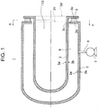
- FIG. 1 is a schematic view illustrating the configuration of the vacuum heat-insulating container 1.
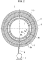
- FIG. 2 is a sectional view taken along the line II-II of FIG. 1 .
- the vacuum heat-insulating container 1 includes an outer cylinder 2 having a bottom and an inner cylinder 3 having a bottom and disposed inside the outer cylinder 2.
- the inner cylinder 3 and the outer cylinder 2 are disposed such that an opening plane 3d of the inner cylinder 3 is located outward of an opening plane 2d of the outer cylinder 2.
- a sealing member 5 has an annular shape and is made of an elastic body having a lower coefficient of heat transfer than the outer cylinder 2 and the inner cylinder 3.
- the sealing member 5 is made of a silicone resin or a Teflon (R) resin.
- the sealing member 5 is squeezed between the first annular wall 2e and the second annular wall 3e so as to seal a space between the outer cylinder 2 and the inner cylinder 3.
- the hermetically closed space between the outer cylinder 2 and the inner cylinder 3 is evacuated by a vacuum pump 7 through a port 6 provided in a side surface of the outer cylinder 2, so that a vacuum space 8 is formed between the outer cylinder 2 and the inner cylinder 3.
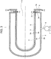
- a shear stress F1 acts in the radial direction on the sealing member 5 that is squeezed between the first annular wall 2e and the second annular wall 3e.
- the sealing member 5 elastically deforms, and is therefore not damaged, under the shear stress exerted thereon in the radial direction by the thermal expansion of the inner cylinder 3.
- damage to a joint part of the outer cylinder 2 and the inner cylinder 3 upon thermal expansion of the inner cylinder 3 can be prevented.
- FIG. 4 is a schematic view illustrating a state where heat of the inner cylinder 3 has been taken away by the housing space 113 that is a space to be cooled.
- the dashed lines in FIG. 4 indicate the inner cylinder 3 before the heat is taken away.
- the inner cylinder 3 undergoes thermal contraction, so that the outer circumferential surface 3b of the inner cylinder 3 moves toward radially inside. Accordingly, the second annular wall 3e also moves toward radially inside.
- the sealing member 5 As the sealing member 5 is fixed in close contact with the cylinders, it is not necessary to fix the sealing member 5 with an adhesive etc. Thus, manufacturing the vacuum heat-insulating container 1 does not require the process of bonding the sealing member 5 to the outer cylinder 2 and the inner cylinder 3, which makes the manufacturing of the vacuum heat-insulating container 1 easier. Moreover, with the sealing member 5 easily replaceable, the maintainability of the vacuum heat-insulating container 1 is also improved.
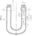
- FIG. 5 is a schematic view showing the schematic configuration of the vacuum heat-insulating container 101.
- FIG. 6 is a sectional view taken along the line VI-VI of FIG. 5 .
- the configuration of the vacuum heat-insulating container 101 is basically the same as that of the vacuum heat-insulating container 1 described using FIG. 1 in Embodiment 1.
- the restraining members 10a, 10b have an arc shape when seen in a cross section along the line VI-VI of FIG. 5 (see FIG. 6 ), and have a predetermined width in a longitudinal direction of the vacuum heat-insulating container 101 (the direction indicated by the arrow X in FIG. 5 ).
- the restraining members 10a, 10b are each in contact with the outer circumferential surface 3b of the inner cylinder 3 and the inner circumferential surface 2a of the outer cylinder 2, and support the load of the inner cylinder 3 as well as restrain the outer circumferential surface 3b of the inner cylinder 3 from moving toward the inner circumferential surface 2a of the outer cylinder 2.
- a clearance between the outer circumferential surface 3b of the inner cylinder 3 and the inner circumferential surface 2a of the outer cylinder 2 is maintained.
- the inner cylinder 3 undergoes thermal expansion when subjected to heat, but the heat of the inner cylinder 3 is hardly conducted to the outer cylinder 2 that is insulated from the inner cylinder 3, so that the outer cylinder 2 hardly undergoes thermal expansion.
- the inner cylinder 3 extends in the longitudinal direction of the vacuum heat-insulating container 101, while the outer cylinder 2 hardly extends in the longitudinal direction of the vacuum heat-insulating container 101. Therefore, when the inner cylinder 3 is subjected to heat and undergoes thermal expansion, friction occurs between the outer circumferential surface 3b of the inner cylinder 3 and the surfaces of the restraining members 10a, 10b facing the outer circumferential surface 3b of the inner cylinder 3.
- the restraining members are disposed at two positions in the longitudinal direction of the vacuum heat-insulating container 101, between the inner circumferential surface 2a of the outer cylinder 2 and the outer circumferential surface 3b of the inner cylinder 3.
- the number of the restraining members is not limited to this example.
- the restraining members may be disposed at two or more positions in the longitudinal direction of the vacuum heat-insulating container 101, between the inner circumferential surface 2a of the outer cylinder 2 and the outer circumferential surface 3b of the inner cylinder 3.
- the cross-sectional shape of the restraining member is not limited to the arc shape shown in FIG. 6 , either.
Landscapes
- Engineering & Computer Science (AREA)
- Mechanical Engineering (AREA)
- Physics & Mathematics (AREA)
- Thermal Sciences (AREA)
- Food Science & Technology (AREA)
- Packages (AREA)
- Thermally Insulated Containers For Foods (AREA)
- Thermal Insulation (AREA)
Abstract
Description
- The present invention relates to a vacuum heat-insulating container.
- A vacuum heat-insulating container is known in which an inner cylinder having a bottom is disposed inside an outer cylinder having also a bottom, so that a vacuum space is formed between the inner cylinder and the outer cylinder. Japanese Patent Application Publication No
2011-219125 - If the inner cylinder and the outer cylinder are integrally joined together at the opening as in the vacuum heat-insulating container described in
JP 2011-219125 A - The present invention provides a vacuum heat-insulating container that can prevent damage to the joint part of the outer cylinder and the inner cylinder upon thermal expansion of the inner cylinder, and that has a sufficiently enhanced heat insulation property.
- The present invention is a vacuum heat-insulating container that includes an outer cylinder having a bottom and an inner cylinder having a bottom and disposed inside the outer cylinder, with a vacuum space formed between the outer cylinder and the inner cylinder. The inner cylinder and the outer cylinder are disposed such that an opening plane of the inner cylinder is located outward of an opening plane of the outer cylinder. The outer cylinder has a first annular wall that extends inwardly along the opening plane of the outer cylinder, and that includes a leading end portion at a distance from an outer circumferential surface of the inner cylinder. The inner cylinder has a second annular wall that extends toward the outside of the inner cylinder along the opening plane of the inner cylinder, and that faces the first annular wall. The vacuum heat-insulating container further includes an annular sealing member that is made of an elastic body having a coefficient of heat transfer lower than a coefficient of heat transfer of the outer cylinder and a coefficient of heat transfer of the inner cylinder, and that is squeezed between the first annular wall and the second annular wall so as to seal the vacuum space.
- The outer cylinder and the inner cylinder are joined together through the sealing member. The sealing member is made of a material having a lower coefficient of heat transfer than the outer cylinder and the inner cylinder. The inner circumferential surface of the outer cylinder and the outer circumferential surface of the inner cylinder are in contact with the vacuum space. Thus, when the inner cylinder is subjected to heat, the heat of the inner cylinder can be prevented from being conducted to the outer cylinder. As a result, the heat insulation property of the vacuum heat-insulating container can be sufficiently enhanced. When the inner cylinder undergoes thermal expansion and the outer circumferential surface of the inner cylinder moves toward radially outside, the second annular wall moves accordingly toward radially outside. Meanwhile, the outer cylinder hardly undergoes thermal expansion, so that the first annular wall hardly moves in the radial direction. As a result, a shear stress acts on the sealing member that is squeezed between the first annular wall and the second annular wall. However, being made of an elastic body, the sealing member elastically deforms, and is therefore not damaged, under the shear stress exerted thereon in the radial direction by the thermal expansion of the inner cylinder. Thus, damage to the joint part of the outer cylinder and the inner cylinder upon thermal expansion of the inner cylinder is prevented.
- The outer cylinder may be disposed such that the opening plane of the outer cylinder is oriented along a vertical direction. A restraining member that restrains the outer circumferential surface of the inner cylinder from moving toward the inner circumferential surface of the outer cylinder may be disposed at the vertically lower side of the vacuum space, and the restraining member may be made of a material having a coefficient of heat transfer lower than the coefficient of heat transfer of the outer cylinder and the coefficient of heat transfer of the inner cylinder.
- In the case where the outer cylinder is disposed such that the opening plane of the outer cylinder is oriented along the vertical direction, if the inner cylinder moves vertically downward under the force of gravity and the outer circumferential surface of the inner cylinder moves toward the inner circumferential surface of the outer cylinder, the leading end portion in the first annular wall of the outer cylinder may come in contact with the outer circumferential surface of the inner cylinder. In the above vacuum heat-insulating container in which the outer cylinder is disposed such that the opening plane of the outer cylinder is oriented along the vertical direction, the restraining member that restrains the outer circumferential surface of the inner cylinder from moving toward the inner circumferential surface of the outer cylinder is disposed at the vertically lower side of the vacuum space. Thus, it is possible to prevent the outer circumferential surface of the inner cylinder from coming in contact with the leading end portion in the first annular wall of the outer cylinder and thereby impairing the heat insulation performance of the vacuum heat-insulating container.
- Moreover, a surface of the restraining member facing the inner cylinder may have a low-friction part in which a frictional force is smaller than a frictional force in the other part.
- The inner cylinder undergoes thermal expansion when subjected to heat, but the heat of the inner cylinder is hardly conducted to the outer cylinder that is insulated from the inner cylinder, so that the outer cylinder hardly undergoes thermal expansion. Specifically, when subjected to heat, the inner cylinder extends in a longitudinal direction of the vacuum heat-insulating container, while the outer cylinder does not extend in the longitudinal direction of the vacuum heat-insulating container. Therefore, when the inner cylinder is subjected to heat and undergoes thermal expansion, friction occurs between the outer circumferential surface of the inner cylinder and the surface of the restraining member facing the outer circumferential surface of the inner cylinder. If the surface of the restraining member facing the outer circumferential surface of the inner cylinder has the low-friction part, the friction occurring between the outer circumferential surface of the inner cylinder and the surface of the restraining member facing the outer circumferential surface of the inner cylinder when the inner cylinder is subjected to heat can be reduced.
- A surface of the restraining member facing the outer circumferential surface of the inner cylinder may have a low-friction part having a coefficient of friction lower than a coefficient of friction of the restraining member.
- The restraining member may have an arc cross-sectional shape and have a predetermined width in the longitudinal direction of the vacuum heat-insulating container.
- According to the present invention, it is possible to prevent damage to the joint part of the outer cylinder and the inner cylinder upon thermal expansion of the inner cylinder, and to sufficiently enhance the heat insulation property.
- Features, advantages, and technical and industrial significance of exemplary embodiments of the invention will be described below with reference to the accompanying drawings, in which like numerals denote like elements, and wherein:
-
FIG. 1 is a schematic view illustrating the configuration of a vacuum heat-insulating container according toEmbodiment 1; -
FIG. 2 is a sectional view taken along the line II-II ofFIG. 1 ; -
FIG. 3 is a schematic view illustrating a state where an inner cylinder has been subjected to heat from a housing space in the vacuum heat-insulating container according toEmbodiment 1; -
FIG. 4 is a schematic view illustrating a state where heat of the inner cylinder has been taken away by the housing space in the vacuum heat-insulating container according toEmbodiment 1; -
FIG. 5 is a schematic view showing the schematic configuration of a vacuum heat-insulating container according toEmbodiment 2; and -
FIG. 6 is a sectional view taken along the line VI-VI ofFIG. 5 . -
Embodiment 1 of the present invention will be described below with reference to the drawings. First, the configuration of a vacuum heat-insulatingcontainer 1 according to this embodiment will be described with reference toFIG. 1 andFIG. 2 .FIG. 1 is a schematic view illustrating the configuration of the vacuum heat-insulatingcontainer 1.FIG. 2 is a sectional view taken along the line II-II ofFIG. 1 . As shown inFIG. 1 andFIG. 2 , the vacuum heat-insulatingcontainer 1 includes anouter cylinder 2 having a bottom and aninner cylinder 3 having a bottom and disposed inside theouter cylinder 2. Theinner cylinder 3 and theouter cylinder 2 are disposed such that anopening plane 3d of theinner cylinder 3 is located outward of anopening plane 2d of theouter cylinder 2. - For example, the
outer cylinder 2 and theinner cylinder 3 are made of stainless steel or of iron and steel. Theouter cylinder 2 has a firstannular wall 2e that extends inwardly along theopening plane 2d of theouter cylinder 2, and that includes a leadingend portion 2c at a distance from an outercircumferential surface 3b of theinner cylinder 3. Theinner cylinder 3 has a secondannular wall 3e that extends toward outside along theopening plane 3d of theinner cylinder 3 and faces the firstannular wall 2e. - A sealing
member 5 has an annular shape and is made of an elastic body having a lower coefficient of heat transfer than theouter cylinder 2 and theinner cylinder 3. For example, the sealingmember 5 is made of a silicone resin or a Teflon (R) resin. The sealingmember 5 is squeezed between the firstannular wall 2e and the secondannular wall 3e so as to seal a space between theouter cylinder 2 and theinner cylinder 3. In this state, the hermetically closed space between theouter cylinder 2 and theinner cylinder 3 is evacuated by avacuum pump 7 through aport 6 provided in a side surface of theouter cylinder 2, so that avacuum space 8 is formed between theouter cylinder 2 and theinner cylinder 3. - Outside air is present outside the
outer cylinder 2, and ahousing space 113 inside theinner cylinder 3 is a space to be heated. Thus, an outercircumferential surface 2b of theouter cylinder 2 is in contact with the outside air, while an innercircumferential surface 3a of theinner cylinder 3 is in contact with thehousing space 113 that is a space to be heated. Theouter cylinder 2 and theinner cylinder 3 are in contact with each other through only thesealing member 5 that is made of a material having a lower coefficient of heat transfer than theouter cylinder 2 and theinner cylinder 3. Moreover, an innercircumferential surface 2a of theouter cylinder 2 and the outercircumferential surface 3b of theinner cylinder 3 are in contact with thevacuum space 8. Thus, when theinner cylinder 3 is subjected to heat from thehousing space 113, the heat of theinner cylinder 3 can be prevented from being conducted to theouter cylinder 2. If the vacuum heat-insulatingcontainer 1 is configured as has been described above, the heat insulation property of the vacuum heat-insulatingcontainer 1 can be sufficiently enhanced. -
FIG. 3 is a schematic view illustrating a state where theinner cylinder 3 has been subjected to heat from thehousing space 113. Here, the dashed lines inFIG. 3 indicate theinner cylinder 3 before being subjected to heat. As shown inFIG. 3 , theinner cylinder 3 undergoes thermal expansion, so that the outercircumferential surface 3b of theinner cylinder 3 moves toward radially outside. Accordingly, the secondannular wall 3e also moves toward radially outside. Meanwhile, theouter cylinder 2 hardly undergoes thermal expansion, so that the firstannular wall 2e hardly moves in the radial direction. As a result, a shear stress F1 acts in the radial direction on the sealingmember 5 that is squeezed between the firstannular wall 2e and the secondannular wall 3e. However, being made of an elastic body, the sealingmember 5 elastically deforms, and is therefore not damaged, under the shear stress exerted thereon in the radial direction by the thermal expansion of theinner cylinder 3. Thus, damage to a joint part of theouter cylinder 2 and theinner cylinder 3 upon thermal expansion of theinner cylinder 3 can be prevented. - In the above embodiment, the housing space inside the inner cylinder of the vacuum heat-insulating container has been described as a space to be heated. However, also when the housing space is a space to be cooled, damage to the vacuum heat-insulating
container 1 due to thermal contraction can be similarly prevented.FIG. 4 is a schematic view illustrating a state where heat of theinner cylinder 3 has been taken away by thehousing space 113 that is a space to be cooled. The dashed lines inFIG. 4 indicate theinner cylinder 3 before the heat is taken away. As shown inFIG. 4 , theinner cylinder 3 undergoes thermal contraction, so that the outercircumferential surface 3b of theinner cylinder 3 moves toward radially inside. Accordingly, the secondannular wall 3e also moves toward radially inside. Meanwhile, theouter cylinder 2 hardly undergoes thermal contraction, so that the firstannular wall 2e hardly moves in the radial direction. As a result, a shear stress F2 acts on the sealingmember 5 that is squeezed between the firstannular wall 2e and the secondannular wall 3e. However, being made of an elastic body, the sealingmember 5 elastically deforms, and is therefore not damaged, under the shear stress exerted thereon in the radial direction by the thermal contraction of theinner cylinder 3. Thus, damage to the joint part of theouter cylinder 2 and theinner cylinder 3 upon thermal contraction of theinner cylinder 3 can be prevented. - As the sealing
member 5 is fixed in close contact with the cylinders, it is not necessary to fix the sealingmember 5 with an adhesive etc. Thus, manufacturing the vacuum heat-insulatingcontainer 1 does not require the process of bonding the sealingmember 5 to theouter cylinder 2 and theinner cylinder 3, which makes the manufacturing of the vacuum heat-insulatingcontainer 1 easier. Moreover, with the sealingmember 5 easily replaceable, the maintainability of the vacuum heat-insulatingcontainer 1 is also improved. - In the above embodiment, the
outer cylinder 2 is disposed such that theopening plane 2d of theouter cylinder 2 is oriented along a vertical direction, i.e., the vacuum heat-insulatingcontainer 1 is placed horizontally. However, the position of the vacuum heat-insulatingcontainer 1 is not limited to this example. Theouter cylinder 2 may be disposed such that theopening plane 2d of theouter cylinder 2 is oriented along a horizontal direction, i.e., the vacuum heat-insulatingcontainer 1 may be disposed vertically. -
Embodiment 2 of the present invention will be described below with reference to the drawings. Parts that are the same as inEmbodiment 1 will be denoted by the same reference signs while description thereof will be omitted. First, the schematic configuration of a vacuum heat-insulatingcontainer 101 according to this embodiment will be described with reference toFIG. 5 andFIG. 6 . -
FIG. 5 is a schematic view showing the schematic configuration of the vacuum heat-insulatingcontainer 101.FIG. 6 is a sectional view taken along the line VI-VI ofFIG. 5 . As shown inFIG. 5 andFIG. 6 , the configuration of the vacuum heat-insulatingcontainer 101 is basically the same as that of the vacuum heat-insulatingcontainer 1 described usingFIG. 1 inEmbodiment 1. In the vacuum heat-insulatingcontainer 101, theouter cylinder 2 is disposed such that theopening plane 2d of theouter cylinder 2 is oriented along the vertical direction, and, unlike in the vacuum heat-insulatingcontainer 1 according toEmbodiment 1, restrainingmembers circumferential surface 3b of theinner cylinder 3 from moving toward the innercircumferential surface 2a of theouter cylinder 2 are disposed at a vertically lower side of thevacuum space 8. The restrainingmembers outer cylinder 2 and theinner cylinder 3. - The restraining
members FIG. 5 (seeFIG. 6 ), and have a predetermined width in a longitudinal direction of the vacuum heat-insulating container 101 (the direction indicated by the arrow X inFIG. 5 ). The restrainingmembers circumferential surface 3b of theinner cylinder 3 and the innercircumferential surface 2a of theouter cylinder 2, and support the load of theinner cylinder 3 as well as restrain the outercircumferential surface 3b of theinner cylinder 3 from moving toward the innercircumferential surface 2a of theouter cylinder 2. Thus, a clearance between the outercircumferential surface 3b of theinner cylinder 3 and the innercircumferential surface 2a of theouter cylinder 2 is maintained. - In the case where the
outer cylinder 2 is disposed such that theopening plane 2d of theouter cylinder 2 is oriented along the vertical direction, i.e., the vacuum heat-insulatingcontainer 1 is disposed horizontally, if theinner cylinder 3 moves vertically downward under the force of gravity and the outercircumferential surface 3b of theinner cylinder 3 moves toward the innercircumferential surface 2a of theouter cylinder 2, theleading end portion 2c in the firstannular wall 2e of theouter cylinder 2 may come in contact with the outercircumferential surface 3b of theinner cylinder 3. Also in such a case, disposing the restrainingmembers circumferential surface 3b of theinner cylinder 3 from moving toward the innercircumferential surface 2a of theouter cylinder 2 at the vertically lower side of thevacuum space 8 can prevent theleading end portion 2c in the firstannular wall 2e of theouter cylinder 2 from coming in contact with the outercircumferential surface 3b of theinner cylinder 3. - Since the restraining
members inner cylinder 3, a material strong enough to withstand the load of theinner cylinder 3 can be selected as the material of the restrainingmembers members - A surface of each of the restraining
members circumferential surface 3b of theinner cylinder 3 may have a low-friction part in which a frictional force is smaller than a frictional force in the other part. In other words, a surface of each of the restrainingmembers circumferential surface 3b of theinner cylinder 3 may have a low-friction part having a coefficient of friction lower than a coefficient of friction of the restrainingmembers members circumferential surface 3b of theinner cylinder 3. - The
inner cylinder 3 undergoes thermal expansion when subjected to heat, but the heat of theinner cylinder 3 is hardly conducted to theouter cylinder 2 that is insulated from theinner cylinder 3, so that theouter cylinder 2 hardly undergoes thermal expansion. Specifically, when subjected to heat, theinner cylinder 3 extends in the longitudinal direction of the vacuum heat-insulatingcontainer 101, while theouter cylinder 2 hardly extends in the longitudinal direction of the vacuum heat-insulatingcontainer 101. Therefore, when theinner cylinder 3 is subjected to heat and undergoes thermal expansion, friction occurs between the outercircumferential surface 3b of theinner cylinder 3 and the surfaces of the restrainingmembers circumferential surface 3b of theinner cylinder 3. If the surface of each of the restrainingmembers circumferential surface 3b of theinner cylinder 3 has the low-friction part, the friction occurring between the outercircumferential surface 3b of theinner cylinder 3 and the surfaces of the restrainingmembers circumferential surface 3b of theinner cylinder 3 when theinner cylinder 3 is subjected to heat can be reduced. - Moreover, if the surface of each of the restraining
members circumferential surface 3b of theinner cylinder 3 has the low-friction part, it is possible to reduce the risk of damage to the outercircumferential surface 3b of theinner cylinder 3 due to friction that is caused by the restrainingmembers circumferential surface 3b of theinner cylinder 3 in the process of inserting theinner cylinder 3 into theouter cylinder 2 during the manufacturing of the vacuum heat-insulatingcontainer 101. - In the vacuum heat-insulating
container 101 shown inFIG. 5 , the restraining members are disposed at two positions in the longitudinal direction of the vacuum heat-insulatingcontainer 101, between the innercircumferential surface 2a of theouter cylinder 2 and the outercircumferential surface 3b of theinner cylinder 3. However, the number of the restraining members is not limited to this example. For example, the restraining members may be disposed at two or more positions in the longitudinal direction of the vacuum heat-insulatingcontainer 101, between the innercircumferential surface 2a of theouter cylinder 2 and the outercircumferential surface 3b of theinner cylinder 3. The cross-sectional shape of the restraining member is not limited to the arc shape shown inFIG. 6 , either. The restraining member may have a cross-sectional shape other than an arc cross-sectional shape, as long as the restraining member can restrain the outercircumferential surface 3b of theinner cylinder 3 from moving toward the innercircumferential surface 2a of theouter cylinder 2 so that theleading end portion 2c in the firstannular wall 2e does not come in contact with the outercircumferential surface 3b of theinner cylinder 3 upon thermal expansion of theinner cylinder 3. - As has been described above, disposing the restraining members inside the
vacuum space 8 between the innercircumferential surface 2a of theouter cylinder 2 and the outercircumferential surface 3b of theinner cylinder 3 can prevent the outercircumferential surface 3b of theinner cylinder 3 from coming in contact with theleading end portion 2c in the firstannular wall 2e of theouter cylinder 2 and thereby impairing the heat insulation performance of the vacuum heat-insulatingcontainer 101. - The present invention is not limited to the above embodiments but can be modified as appropriate within the scope of the gist of the invention.
Claims (5)
- A vacuum heat-insulating container (1) comprising:an outer cylinder (2) having a bottom, andan inner cylinder (3) having a bottom and disposed inside the outer cylinder (2),wherein
a vacuum space (8) is formed between the outer cylinder (2) and the inner cylinder (3),
the inner cylinder (3) and the outer cylinder (2) are disposed such that an opening plane (3d) of the inner cylinder (3) is located outward of an opening plane (2d) of the outer cylinder (2),
the outer cylinder (2) has a first annular wall (2e) that extends inwardly along the opening plane (2d) of the outer cylinder (2), and that includes a leading end portion (2c) at a distance from an outer circumferential surface of the inner cylinder (3),
the inner cylinder (3) has a second annular wall (3e) that extends toward an outside of the inner cylinder (3) along the opening plane (3d) of the inner cylinder (3), and that faces the first annular wall (2e), and
the vacuum heat-insulating container (1) includes an annular sealing member (5) that is made of an elastic body having a coefficient of heat transfer lower than a coefficient of heat transfer of the outer cylinder (2) and a coefficient of heat transfer of the inner cylinder (3), and that is squeezed between the first annular wall (2e) and the second annular wall (3e) so as to seal the vacuum space (8). - The vacuum heat-insulating container (1) according to claim 1, wherein
the outer cylinder (2) is disposed such that the opening plane (2d) of the outer cylinder (2) is oriented along a vertical direction,
a restraining member (10a, 10b) that restrains the outer circumferential surface of the inner cylinder (3) from moving toward an inner circumferential surface of the outer cylinder (2) is disposed at a vertically lower side of the vacuum space (8), and
the restraining member (10a, 10b) is made of a material having a coefficient of heat transfer lower than the coefficient of heat transfer of the outer cylinder (2) and the coefficient of heat transfer of the inner cylinder (3). - The vacuum heat-insulating container (1) according to claim 2, wherein a surface of the restraining member (10a, 10b) facing the inner cylinder (3) has a low-friction part in which a frictional force is smaller than a frictional force in the other part.
- The vacuum heat-insulating container (1) according to claim 2, wherein a surface of the restraining member (10a, 10b) facing the outer circumferential surface of the inner cylinder (3) has a low-friction part having a coefficient of friction lower than a coefficient of friction of the restraining member (10a, 10b).
- The vacuum heat-insulating container (1) according to any one of claims 2 to 4, wherein the restraining member (10a, 10b) has an arc cross-sectional shape and has a predetermined width in a longitudinal direction of the vacuum heat-insulating container (1).
Applications Claiming Priority (1)
| Application Number | Priority Date | Filing Date | Title |
|---|---|---|---|
| JP2016224993A JP6481674B2 (en) | 2016-11-18 | 2016-11-18 | Vacuum insulated container |
Publications (2)
| Publication Number | Publication Date |
|---|---|
| EP3323754A1 true EP3323754A1 (en) | 2018-05-23 |
| EP3323754B1 EP3323754B1 (en) | 2020-07-22 |
Family
ID=60244916
Family Applications (1)
| Application Number | Title | Priority Date | Filing Date |
|---|---|---|---|
| EP17199560.8A Active EP3323754B1 (en) | 2016-11-18 | 2017-11-01 | Vacuum heat-insulating container |
Country Status (8)
| Country | Link |
|---|---|
| US (1) | US10661970B2 (en) |
| EP (1) | EP3323754B1 (en) |
| JP (1) | JP6481674B2 (en) |
| KR (1) | KR101982703B1 (en) |
| CN (1) | CN108146872B (en) |
| BR (1) | BR102017024314A2 (en) |
| ES (1) | ES2812793T3 (en) |
| RU (1) | RU2687688C2 (en) |
Families Citing this family (6)
| Publication number | Priority date | Publication date | Assignee | Title |
|---|---|---|---|---|
| JP6515913B2 (en) | 2016-12-22 | 2019-05-22 | トヨタ自動車株式会社 | Vacuum insulation container |
| JP6733573B2 (en) | 2017-02-15 | 2020-08-05 | トヨタ自動車株式会社 | Decompression insulation piping structure |
| JP6904168B2 (en) | 2017-08-28 | 2021-07-14 | トヨタ自動車株式会社 | Vacuum insulation container |
| WO2022076448A1 (en) * | 2020-10-06 | 2022-04-14 | SST Living Corporation | Vacuum insulated storage containers |
| CN114715518B (en) * | 2022-04-14 | 2023-09-05 | 安徽登云玻璃科技有限公司 | A glass vessel with heat preservation function |
| US12577032B2 (en) * | 2023-10-03 | 2026-03-17 | Arizechukwu Nwosu | Container for retrievably storing substances and retaining temperatures of the substances |
Citations (5)
| Publication number | Priority date | Publication date | Assignee | Title |
|---|---|---|---|---|
| FR7416E (en) * | 1907-02-07 | 1907-07-31 | Jules Gamard | Insulated box |
| US1352844A (en) * | 1920-05-03 | 1920-09-14 | Landers Frary & Clark | Vacuum-bottle |
| US3760971A (en) * | 1970-03-23 | 1973-09-25 | Marathon Oil Co | Liquid cryogen storage tank for shore, ship or barge |
| GB2434440A (en) * | 2005-03-23 | 2007-07-25 | Thermos Kk | Heat insulated container |
| JP2011219125A (en) | 2010-04-08 | 2011-11-04 | Thermos Kk | Metallic vacuum heat insulating container |
Family Cites Families (19)
| Publication number | Priority date | Publication date | Assignee | Title |
|---|---|---|---|---|
| US1172247A (en) * | 1910-11-23 | 1916-02-22 | Eugene L Greenewald | Vacuum-bottle. |
| US1281966A (en) * | 1915-09-15 | 1918-10-15 | Payson Irwin | Vacuum-container. |
| US1260046A (en) * | 1917-01-12 | 1918-03-19 | Waterbury Mfg Co | Vacuum-bottle. |
| US2666979A (en) | 1948-03-06 | 1954-01-26 | Dusen Engineering Company Van | Method for attaching members by vacuum pressure |
| US3863794A (en) * | 1973-04-11 | 1975-02-04 | Brighton Corp Ltd | Vacuum retaining jar |
| US4200199A (en) * | 1977-09-01 | 1980-04-29 | Aladdin Industries, Incorporated | Vacuum bottle construction |
| JPS642785U (en) * | 1987-06-26 | 1989-01-10 | ||
| JPH0214885U (en) * | 1988-07-12 | 1990-01-30 | ||
| JP2517021Y2 (en) * | 1990-07-10 | 1996-11-13 | 日本酸素株式会社 | Vacuum insulation container made of synthetic resin |
| JPH04127498U (en) * | 1991-05-14 | 1992-11-19 | 株式会社クボタ | Structure of vacuum insulated box |
| JP2002068324A (en) * | 2000-08-30 | 2002-03-08 | Nippon Sanso Corp | Insulated container |
| US6626326B2 (en) * | 2001-01-11 | 2003-09-30 | Thermos L.L.C. | Vacuum insulated can holder |
| JP2004017994A (en) * | 2002-06-13 | 2004-01-22 | Thermos Kk | Insulated container and method for manufacturing the same |
| CA2590409A1 (en) * | 2005-03-28 | 2006-10-05 | Thermos K.K. | Heat insulated container |
| CA2589805A1 (en) * | 2005-03-28 | 2006-10-05 | Thermos K.K. | Heat insulated container and manufacturing method thereof |
| DE102005031095B4 (en) * | 2005-06-30 | 2014-09-25 | Weberit-Werke Dräbing Gmbh | Arrangement of hollow bodies |
| JP2008050020A (en) * | 2006-08-23 | 2008-03-06 | Matsushita Electric Ind Co Ltd | Synthetic resin insulated container |
| US9254063B2 (en) * | 2012-02-21 | 2016-02-09 | Tervis Tumbler Company | Double walled insulated container with rechargeable vacuum |
| US9585501B1 (en) * | 2013-11-12 | 2017-03-07 | L. Robert Hamelink | Beverage cup insulating seal member and associated insulated beverage cup assembly |
-
2016
- 2016-11-18 JP JP2016224993A patent/JP6481674B2/en active Active
-
2017
- 2017-10-27 KR KR1020170141268A patent/KR101982703B1/en active Active
- 2017-10-31 RU RU2017137862A patent/RU2687688C2/en active
- 2017-10-31 US US15/799,172 patent/US10661970B2/en active Active
- 2017-11-01 ES ES17199560T patent/ES2812793T3/en active Active
- 2017-11-01 EP EP17199560.8A patent/EP3323754B1/en active Active
- 2017-11-13 BR BR102017024314-1A patent/BR102017024314A2/en not_active Application Discontinuation
- 2017-11-15 CN CN201711169309.3A patent/CN108146872B/en active Active
Patent Citations (5)
| Publication number | Priority date | Publication date | Assignee | Title |
|---|---|---|---|---|
| FR7416E (en) * | 1907-02-07 | 1907-07-31 | Jules Gamard | Insulated box |
| US1352844A (en) * | 1920-05-03 | 1920-09-14 | Landers Frary & Clark | Vacuum-bottle |
| US3760971A (en) * | 1970-03-23 | 1973-09-25 | Marathon Oil Co | Liquid cryogen storage tank for shore, ship or barge |
| GB2434440A (en) * | 2005-03-23 | 2007-07-25 | Thermos Kk | Heat insulated container |
| JP2011219125A (en) | 2010-04-08 | 2011-11-04 | Thermos Kk | Metallic vacuum heat insulating container |
Also Published As
| Publication number | Publication date |
|---|---|
| RU2017137862A (en) | 2019-04-30 |
| KR101982703B1 (en) | 2019-05-27 |
| BR102017024314A2 (en) | 2018-07-31 |
| US20180141740A1 (en) | 2018-05-24 |
| RU2017137862A3 (en) | 2019-04-30 |
| KR20180056365A (en) | 2018-05-28 |
| RU2687688C2 (en) | 2019-05-15 |
| JP6481674B2 (en) | 2019-03-13 |
| EP3323754B1 (en) | 2020-07-22 |
| CN108146872A (en) | 2018-06-12 |
| ES2812793T3 (en) | 2021-03-18 |
| JP2018079972A (en) | 2018-05-24 |
| CN108146872B (en) | 2019-05-21 |
| US10661970B2 (en) | 2020-05-26 |
Similar Documents
| Publication | Publication Date | Title |
|---|---|---|
| EP3323754B1 (en) | Vacuum heat-insulating container | |
| US8956067B2 (en) | Split case of a magnetic coupling, in particular of a magnetic coupling pump | |
| KR101506189B1 (en) | An insulated gasket for high temperature and pressure having sealing pad | |
| US11333289B2 (en) | Decompression heat-insulating pipe structure | |
| KR20210114565A (en) | Seal member | |
| CN108072277A (en) | Vacuum double structure and heat-treatment furnace | |
| KR101506190B1 (en) | An insulated gasket for high temperature and pressure having metal o ring | |
| US11509190B2 (en) | Motor and method of producing the same | |
| US10507967B2 (en) | Vacuum insulating container | |
| US9901004B2 (en) | Housing for electronic control unit | |
| US8896174B2 (en) | Active magnetic bearing | |
| JP2019002593A (en) | Thermal insulation wall for heating furnace | |
| US10443776B2 (en) | Decompression heat-insulating pipe structure | |
| JP2019060085A (en) | Glass panel and fitting | |
| JP2018080779A (en) | Vacuum insulation structure | |
| US20220037102A1 (en) | Electronic component | |
| JP2017048818A5 (en) | ||
| US12532427B2 (en) | Housing assembly comprising a seal | |
| JP2018204737A (en) | Insulated wall structure | |
| JP2018121825A (en) | Insulated wall structure | |
| JP2018204637A (en) | Insulated wall structure | |
| JP2018203330A (en) | Double heat insulating container | |
| JP2019085116A (en) | Duplex insulating container | |
| JP2018071600A (en) | Vacuum insulated double tube structure | |
| JP2019007521A (en) | Thermal insulation lid structure |
Legal Events
| Date | Code | Title | Description |
|---|---|---|---|
| PUAI | Public reference made under article 153(3) epc to a published international application that has entered the european phase |
Free format text: ORIGINAL CODE: 0009012 |
|
| STAA | Information on the status of an ep patent application or granted ep patent |
Free format text: STATUS: REQUEST FOR EXAMINATION WAS MADE |
|
| 17P | Request for examination filed |
Effective date: 20171101 |
|
| AK | Designated contracting states |
Kind code of ref document: A1 Designated state(s): AL AT BE BG CH CY CZ DE DK EE ES FI FR GB GR HR HU IE IS IT LI LT LU LV MC MK MT NL NO PL PT RO RS SE SI SK SM TR |
|
| AX | Request for extension of the european patent |
Extension state: BA ME |
|
| STAA | Information on the status of an ep patent application or granted ep patent |
Free format text: STATUS: EXAMINATION IS IN PROGRESS |
|
| 17Q | First examination report despatched |
Effective date: 20190124 |
|
| GRAP | Despatch of communication of intention to grant a patent |
Free format text: ORIGINAL CODE: EPIDOSNIGR1 |
|
| STAA | Information on the status of an ep patent application or granted ep patent |
Free format text: STATUS: GRANT OF PATENT IS INTENDED |
|
| INTG | Intention to grant announced |
Effective date: 20200421 |
|
| GRAS | Grant fee paid |
Free format text: ORIGINAL CODE: EPIDOSNIGR3 |
|
| GRAA | (expected) grant |
Free format text: ORIGINAL CODE: 0009210 |
|
| STAA | Information on the status of an ep patent application or granted ep patent |
Free format text: STATUS: THE PATENT HAS BEEN GRANTED |
|
| AK | Designated contracting states |
Kind code of ref document: B1 Designated state(s): AL AT BE BG CH CY CZ DE DK EE ES FI FR GB GR HR HU IE IS IT LI LT LU LV MC MK MT NL NO PL PT RO RS SE SI SK SM TR |
|
| REG | Reference to a national code |
Ref country code: GB Ref legal event code: FG4D |
|
| REG | Reference to a national code |
Ref country code: CH Ref legal event code: EP |
|
| REG | Reference to a national code |
Ref country code: DE Ref legal event code: R096 Ref document number: 602017020099 Country of ref document: DE |
|
| REG | Reference to a national code |
Ref country code: AT Ref legal event code: REF Ref document number: 1293177 Country of ref document: AT Kind code of ref document: T Effective date: 20200815 |
|
| REG | Reference to a national code |
Ref country code: IE Ref legal event code: FG4D |
|
| REG | Reference to a national code |
Ref country code: LT Ref legal event code: MG4D |
|
| REG | Reference to a national code |
Ref country code: AT Ref legal event code: MK05 Ref document number: 1293177 Country of ref document: AT Kind code of ref document: T Effective date: 20200722 |
|
| PG25 | Lapsed in a contracting state [announced via postgrant information from national office to epo] |
Ref country code: GR Free format text: LAPSE BECAUSE OF FAILURE TO SUBMIT A TRANSLATION OF THE DESCRIPTION OR TO PAY THE FEE WITHIN THE PRESCRIBED TIME-LIMIT Effective date: 20201023 Ref country code: AT Free format text: LAPSE BECAUSE OF FAILURE TO SUBMIT A TRANSLATION OF THE DESCRIPTION OR TO PAY THE FEE WITHIN THE PRESCRIBED TIME-LIMIT Effective date: 20200722 Ref country code: NO Free format text: LAPSE BECAUSE OF FAILURE TO SUBMIT A TRANSLATION OF THE DESCRIPTION OR TO PAY THE FEE WITHIN THE PRESCRIBED TIME-LIMIT Effective date: 20201022 Ref country code: BG Free format text: LAPSE BECAUSE OF FAILURE TO SUBMIT A TRANSLATION OF THE DESCRIPTION OR TO PAY THE FEE WITHIN THE PRESCRIBED TIME-LIMIT Effective date: 20201022 Ref country code: PT Free format text: LAPSE BECAUSE OF FAILURE TO SUBMIT A TRANSLATION OF THE DESCRIPTION OR TO PAY THE FEE WITHIN THE PRESCRIBED TIME-LIMIT Effective date: 20201123 Ref country code: FI Free format text: LAPSE BECAUSE OF FAILURE TO SUBMIT A TRANSLATION OF THE DESCRIPTION OR TO PAY THE FEE WITHIN THE PRESCRIBED TIME-LIMIT Effective date: 20200722 Ref country code: LT Free format text: LAPSE BECAUSE OF FAILURE TO SUBMIT A TRANSLATION OF THE DESCRIPTION OR TO PAY THE FEE WITHIN THE PRESCRIBED TIME-LIMIT Effective date: 20200722 Ref country code: SE Free format text: LAPSE BECAUSE OF FAILURE TO SUBMIT A TRANSLATION OF THE DESCRIPTION OR TO PAY THE FEE WITHIN THE PRESCRIBED TIME-LIMIT Effective date: 20200722 Ref country code: HR Free format text: LAPSE BECAUSE OF FAILURE TO SUBMIT A TRANSLATION OF THE DESCRIPTION OR TO PAY THE FEE WITHIN THE PRESCRIBED TIME-LIMIT Effective date: 20200722 |
|
| PG25 | Lapsed in a contracting state [announced via postgrant information from national office to epo] |
Ref country code: LV Free format text: LAPSE BECAUSE OF FAILURE TO SUBMIT A TRANSLATION OF THE DESCRIPTION OR TO PAY THE FEE WITHIN THE PRESCRIBED TIME-LIMIT Effective date: 20200722 Ref country code: PL Free format text: LAPSE BECAUSE OF FAILURE TO SUBMIT A TRANSLATION OF THE DESCRIPTION OR TO PAY THE FEE WITHIN THE PRESCRIBED TIME-LIMIT Effective date: 20200722 Ref country code: RS Free format text: LAPSE BECAUSE OF FAILURE TO SUBMIT A TRANSLATION OF THE DESCRIPTION OR TO PAY THE FEE WITHIN THE PRESCRIBED TIME-LIMIT Effective date: 20200722 Ref country code: IS Free format text: LAPSE BECAUSE OF FAILURE TO SUBMIT A TRANSLATION OF THE DESCRIPTION OR TO PAY THE FEE WITHIN THE PRESCRIBED TIME-LIMIT Effective date: 20201122 |
|
| REG | Reference to a national code |
Ref country code: ES Ref legal event code: FG2A Ref document number: 2812793 Country of ref document: ES Kind code of ref document: T3 Effective date: 20210318 |
|
| PG25 | Lapsed in a contracting state [announced via postgrant information from national office to epo] |
Ref country code: NL Free format text: LAPSE BECAUSE OF FAILURE TO SUBMIT A TRANSLATION OF THE DESCRIPTION OR TO PAY THE FEE WITHIN THE PRESCRIBED TIME-LIMIT Effective date: 20200722 |
|
| REG | Reference to a national code |
Ref country code: DE Ref legal event code: R097 Ref document number: 602017020099 Country of ref document: DE |
|
| PG25 | Lapsed in a contracting state [announced via postgrant information from national office to epo] |
Ref country code: RO Free format text: LAPSE BECAUSE OF FAILURE TO SUBMIT A TRANSLATION OF THE DESCRIPTION OR TO PAY THE FEE WITHIN THE PRESCRIBED TIME-LIMIT Effective date: 20200722 Ref country code: DK Free format text: LAPSE BECAUSE OF FAILURE TO SUBMIT A TRANSLATION OF THE DESCRIPTION OR TO PAY THE FEE WITHIN THE PRESCRIBED TIME-LIMIT Effective date: 20200722 Ref country code: CZ Free format text: LAPSE BECAUSE OF FAILURE TO SUBMIT A TRANSLATION OF THE DESCRIPTION OR TO PAY THE FEE WITHIN THE PRESCRIBED TIME-LIMIT Effective date: 20200722 Ref country code: EE Free format text: LAPSE BECAUSE OF FAILURE TO SUBMIT A TRANSLATION OF THE DESCRIPTION OR TO PAY THE FEE WITHIN THE PRESCRIBED TIME-LIMIT Effective date: 20200722 Ref country code: SM Free format text: LAPSE BECAUSE OF FAILURE TO SUBMIT A TRANSLATION OF THE DESCRIPTION OR TO PAY THE FEE WITHIN THE PRESCRIBED TIME-LIMIT Effective date: 20200722 |
|
| PLBE | No opposition filed within time limit |
Free format text: ORIGINAL CODE: 0009261 |
|
| STAA | Information on the status of an ep patent application or granted ep patent |
Free format text: STATUS: NO OPPOSITION FILED WITHIN TIME LIMIT |
|
| PG25 | Lapsed in a contracting state [announced via postgrant information from national office to epo] |
Ref country code: AL Free format text: LAPSE BECAUSE OF FAILURE TO SUBMIT A TRANSLATION OF THE DESCRIPTION OR TO PAY THE FEE WITHIN THE PRESCRIBED TIME-LIMIT Effective date: 20200722 |
|
| 26N | No opposition filed |
Effective date: 20210423 |
|
| PG25 | Lapsed in a contracting state [announced via postgrant information from national office to epo] |
Ref country code: SK Free format text: LAPSE BECAUSE OF FAILURE TO SUBMIT A TRANSLATION OF THE DESCRIPTION OR TO PAY THE FEE WITHIN THE PRESCRIBED TIME-LIMIT Effective date: 20200722 Ref country code: MC Free format text: LAPSE BECAUSE OF FAILURE TO SUBMIT A TRANSLATION OF THE DESCRIPTION OR TO PAY THE FEE WITHIN THE PRESCRIBED TIME-LIMIT Effective date: 20200722 |
|
| REG | Reference to a national code |
Ref country code: CH Ref legal event code: PL |
|
| PG25 | Lapsed in a contracting state [announced via postgrant information from national office to epo] |
Ref country code: LU Free format text: LAPSE BECAUSE OF NON-PAYMENT OF DUE FEES Effective date: 20201101 |
|
| REG | Reference to a national code |
Ref country code: BE Ref legal event code: MM Effective date: 20201130 |
|
| PG25 | Lapsed in a contracting state [announced via postgrant information from national office to epo] |
Ref country code: LI Free format text: LAPSE BECAUSE OF NON-PAYMENT OF DUE FEES Effective date: 20201130 Ref country code: SI Free format text: LAPSE BECAUSE OF FAILURE TO SUBMIT A TRANSLATION OF THE DESCRIPTION OR TO PAY THE FEE WITHIN THE PRESCRIBED TIME-LIMIT Effective date: 20200722 Ref country code: CH Free format text: LAPSE BECAUSE OF NON-PAYMENT OF DUE FEES Effective date: 20201130 |
|
| REG | Reference to a national code |
Ref country code: NL Ref legal event code: MP Effective date: 20200722 |
|
| PG25 | Lapsed in a contracting state [announced via postgrant information from national office to epo] |
Ref country code: IE Free format text: LAPSE BECAUSE OF NON-PAYMENT OF DUE FEES Effective date: 20201101 |
|
| PG25 | Lapsed in a contracting state [announced via postgrant information from national office to epo] |
Ref country code: TR Free format text: LAPSE BECAUSE OF FAILURE TO SUBMIT A TRANSLATION OF THE DESCRIPTION OR TO PAY THE FEE WITHIN THE PRESCRIBED TIME-LIMIT Effective date: 20200722 Ref country code: MT Free format text: LAPSE BECAUSE OF FAILURE TO SUBMIT A TRANSLATION OF THE DESCRIPTION OR TO PAY THE FEE WITHIN THE PRESCRIBED TIME-LIMIT Effective date: 20200722 Ref country code: CY Free format text: LAPSE BECAUSE OF FAILURE TO SUBMIT A TRANSLATION OF THE DESCRIPTION OR TO PAY THE FEE WITHIN THE PRESCRIBED TIME-LIMIT Effective date: 20200722 |
|
| PG25 | Lapsed in a contracting state [announced via postgrant information from national office to epo] |
Ref country code: MK Free format text: LAPSE BECAUSE OF FAILURE TO SUBMIT A TRANSLATION OF THE DESCRIPTION OR TO PAY THE FEE WITHIN THE PRESCRIBED TIME-LIMIT Effective date: 20200722 |
|
| PG25 | Lapsed in a contracting state [announced via postgrant information from national office to epo] |
Ref country code: BE Free format text: LAPSE BECAUSE OF NON-PAYMENT OF DUE FEES Effective date: 20201130 |
|
| PGFP | Annual fee paid to national office [announced via postgrant information from national office to epo] |
Ref country code: IT Payment date: 20221011 Year of fee payment: 6 Ref country code: ES Payment date: 20221206 Year of fee payment: 6 |
|
| P01 | Opt-out of the competence of the unified patent court (upc) registered |
Effective date: 20230427 |
|
| PG25 | Lapsed in a contracting state [announced via postgrant information from national office to epo] |
Ref country code: IT Free format text: LAPSE BECAUSE OF NON-PAYMENT OF DUE FEES Effective date: 20231101 |
|
| REG | Reference to a national code |
Ref country code: ES Ref legal event code: FD2A Effective date: 20241230 |
|
| PG25 | Lapsed in a contracting state [announced via postgrant information from national office to epo] |
Ref country code: IT Free format text: LAPSE BECAUSE OF NON-PAYMENT OF DUE FEES Effective date: 20231101 |
|
| PG25 | Lapsed in a contracting state [announced via postgrant information from national office to epo] |
Ref country code: ES Free format text: LAPSE BECAUSE OF NON-PAYMENT OF DUE FEES Effective date: 20231102 |
|
| PG25 | Lapsed in a contracting state [announced via postgrant information from national office to epo] |
Ref country code: ES Free format text: LAPSE BECAUSE OF NON-PAYMENT OF DUE FEES Effective date: 20231102 |
|
| REG | Reference to a national code |
Ref country code: DE Ref legal event code: R084 Ref document number: 602017020099 Country of ref document: DE |
|
| PGFP | Annual fee paid to national office [announced via postgrant information from national office to epo] |
Ref country code: FR Payment date: 20250930 Year of fee payment: 9 |
|
| PGFP | Annual fee paid to national office [announced via postgrant information from national office to epo] |
Ref country code: DE Payment date: 20250930 Year of fee payment: 9 |
|
| PGFP | Annual fee paid to national office [announced via postgrant information from national office to epo] |
Ref country code: GB Payment date: 20251001 Year of fee payment: 9 |
|
| REG | Reference to a national code |
Ref country code: GB Ref legal event code: 746 Effective date: 20260112 |