US9254063B2 - Double walled insulated container with rechargeable vacuum - Google Patents
Double walled insulated container with rechargeable vacuum Download PDFInfo
- Publication number
- US9254063B2 US9254063B2 US13/401,031 US201213401031A US9254063B2 US 9254063 B2 US9254063 B2 US 9254063B2 US 201213401031 A US201213401031 A US 201213401031A US 9254063 B2 US9254063 B2 US 9254063B2
- Authority
- US
- United States
- Prior art keywords
- insulating space
- container
- vent
- valve seat
- outer member
- Prior art date
- Legal status (The legal status is an assumption and is not a legal conclusion. Google has not performed a legal analysis and makes no representation as to the accuracy of the status listed.)
- Expired - Fee Related, expires
Links
- 239000007788 liquid Substances 0.000 claims abstract description 18
- 239000004033 plastic Substances 0.000 claims abstract description 17
- 229920003023 plastic Polymers 0.000 claims abstract description 17
- 238000004891 communication Methods 0.000 claims abstract description 6
- 239000007789 gas Substances 0.000 claims description 34
- 239000000463 material Substances 0.000 claims description 26
- 239000012080 ambient air Substances 0.000 claims 1
- 239000012528 membrane Substances 0.000 description 11
- 238000009413 insulation Methods 0.000 description 6
- 239000000853 adhesive Substances 0.000 description 4
- 230000001070 adhesive effect Effects 0.000 description 4
- 230000000712 assembly Effects 0.000 description 4
- 238000000429 assembly Methods 0.000 description 4
- 239000000356 contaminant Substances 0.000 description 4
- XLYOFNOQVPJJNP-UHFFFAOYSA-N water Substances O XLYOFNOQVPJJNP-UHFFFAOYSA-N 0.000 description 4
- 230000007423 decrease Effects 0.000 description 3
- 238000005406 washing Methods 0.000 description 3
- 229920000690 Tyvek Polymers 0.000 description 2
- 238000010276 construction Methods 0.000 description 2
- 239000012611 container material Substances 0.000 description 2
- 238000001816 cooling Methods 0.000 description 2
- 230000002093 peripheral effect Effects 0.000 description 2
- 230000035699 permeability Effects 0.000 description 2
- 230000005855 radiation Effects 0.000 description 2
- 238000012546 transfer Methods 0.000 description 2
- 238000003466 welding Methods 0.000 description 2
- 229920001474 Flashspun fabric Polymers 0.000 description 1
- 229920000544 Gore-Tex Polymers 0.000 description 1
- 241001180747 Hottea Species 0.000 description 1
- CDBYLPFSWZWCQE-UHFFFAOYSA-L Sodium Carbonate Chemical compound [Na+].[Na+].[O-]C([O-])=O CDBYLPFSWZWCQE-UHFFFAOYSA-L 0.000 description 1
- 239000004775 Tyvek Substances 0.000 description 1
- 235000013361 beverage Nutrition 0.000 description 1
- 230000000295 complement effect Effects 0.000 description 1
- 230000000254 damaging effect Effects 0.000 description 1
- 238000011161 development Methods 0.000 description 1
- -1 e.g. Polymers 0.000 description 1
- 239000004744 fabric Substances 0.000 description 1
- 239000004751 flashspun nonwoven Substances 0.000 description 1
- 239000012530 fluid Substances 0.000 description 1
- 239000011521 glass Substances 0.000 description 1
- 239000012212 insulator Substances 0.000 description 1
- 238000004519 manufacturing process Methods 0.000 description 1
- 229910052751 metal Inorganic materials 0.000 description 1
- 239000002184 metal Substances 0.000 description 1
- 150000002739 metals Chemical class 0.000 description 1
- 238000000034 method Methods 0.000 description 1
- 238000011160 research Methods 0.000 description 1
- 229920001169 thermoplastic Polymers 0.000 description 1
- 239000004416 thermosoftening plastic Substances 0.000 description 1
Images


Classifications
-
- A—HUMAN NECESSITIES
- A47—FURNITURE; DOMESTIC ARTICLES OR APPLIANCES; COFFEE MILLS; SPICE MILLS; SUCTION CLEANERS IN GENERAL
- A47J—KITCHEN EQUIPMENT; COFFEE MILLS; SPICE MILLS; APPARATUS FOR MAKING BEVERAGES
- A47J41/00—Thermally-insulated vessels, e.g. flasks, jugs, jars
- A47J41/02—Vacuum-jacket vessels, e.g. vacuum bottles
-
- A—HUMAN NECESSITIES
- A47—FURNITURE; DOMESTIC ARTICLES OR APPLIANCES; COFFEE MILLS; SPICE MILLS; SUCTION CLEANERS IN GENERAL
- A47J—KITCHEN EQUIPMENT; COFFEE MILLS; SPICE MILLS; APPARATUS FOR MAKING BEVERAGES
- A47J41/00—Thermally-insulated vessels, e.g. flasks, jugs, jars
- A47J41/0055—Constructional details of the elements forming the thermal insulation
- A47J41/0072—Double walled vessels comprising a single insulating layer between inner and outer walls
- A47J41/0077—Double walled vessels comprising a single insulating layer between inner and outer walls made of two vessels inserted in each other
-
- B—PERFORMING OPERATIONS; TRANSPORTING
- B65—CONVEYING; PACKING; STORING; HANDLING THIN OR FILAMENTARY MATERIAL
- B65D—CONTAINERS FOR STORAGE OR TRANSPORT OF ARTICLES OR MATERIALS, e.g. BAGS, BARRELS, BOTTLES, BOXES, CANS, CARTONS, CRATES, DRUMS, JARS, TANKS, HOPPERS, FORWARDING CONTAINERS; ACCESSORIES, CLOSURES, OR FITTINGS THEREFOR; PACKAGING ELEMENTS; PACKAGES
- B65D81/00—Containers, packaging elements, or packages, for contents presenting particular transport or storage problems, or adapted to be used for non-packaging purposes after removal of contents
- B65D81/38—Containers, packaging elements, or packages, for contents presenting particular transport or storage problems, or adapted to be used for non-packaging purposes after removal of contents with thermal insulation
- B65D81/3837—Containers, packaging elements, or packages, for contents presenting particular transport or storage problems, or adapted to be used for non-packaging purposes after removal of contents with thermal insulation rigid container in the form of a bottle, jar or like container
Definitions
- This invention relates generally to insulated containers and more particularly to double walled insulated containers.
- Insulated containers or vessels commonly include an outer member or vessel in which an inner member or vessel is located, with the space between those vessels forming an insulating region surrounding the inner vessel.
- heat can be transferred between the inner and outer vessel by three methods. They are conduction, radiation and convection. Air and most gases which can be disposed within the insulating space are good insulators against conduction. However, they easily convect.
- containers frequently make use of a narrow insulating space to decrease the amount of convection.
- Another manner for providing effective insulation is to reduce the amount of gas in the insulating space, i.e., create some vacuum therein. This action further decreases convection. In addition, with less media present it also reduces conduction heat transfer.
- the inner walls of the insulating space can be covered with a highly reflective surface to reflect back the radiated energy.
- One such double wall, low pressure insulated container having with a highly reflective surface is the traditional vacuum bottle.
- traditional vacuum bottles are expensive due to having to be truly hermetically sealed. If they leak, even slowly, they lose a large part of their insulation ability. They are also typically constructed from glass or metals, because plastics are gas permeable.
- Double wall insulated containers like those described above, also exhibit a problem when subjected to the high temperatures encountered when they are washed in a dishwasher.
- the high heat increases the pressure of the gas volume trapped in the insulation space between the container's double walls. This is especially a problem in the case of low cost plastic containers.
- the increased pressure can either burst the containment or distort the container. While placing a hole in the container to vent the pressure in the insulating space to prevent such potentially damaging action is a potential solution, it necessarily allows the insulating space to fill with water or other contaminants. This decreases the vessel's insulating ability and may be a sanitary hazard.
- the subject invention addresses that need.
- the subject invention is directed to a container comprising an outer member, an inner member, an insulating space and a vent assembly.
- the outer member is formed of a plastic material and has a sidewall.
- the inner member is formed of a plastic material and has a sidewall.
- the inner member is disposed within the outer member, with the insulating space being located between the sidewalls of those members.
- the vent assembly is located in the outer member in communication with the insulating space.
- the vent assembly is arranged, e.g., includes a gas permeable membrane, to prevent liquid from entering into the insulating space.
- the insulating space includes some vacuum therein and the vent assembly is arranged, e.g., includes a one-way check valve, to equalize the internal pressure within the insulating space and the ambient atmospheric pressure surrounding the outer member to allow higher internal pressure within the insulating space to vent to the ambient atmosphere when the container is heated and to close off to seal the insulating space to maintain the vacuum therein when the container is cooled.
- the vent assembly is arranged, e.g., includes a one-way check valve, to equalize the internal pressure within the insulating space and the ambient atmospheric pressure surrounding the outer member to allow higher internal pressure within the insulating space to vent to the ambient atmosphere when the container is heated and to close off to seal the insulating space to maintain the vacuum therein when the container is cooled.
- the vent assembly is arranged to prevent liquid from entering into the insulating space and to equalize the internal pressure within the insulating space and the ambient atmospheric pressure surrounding the outer member to allow higher internal pressure within the insulating space to vent to the ambient atmosphere when the container is heated and to close off to seal the insulating space to maintain the vacuum therein when the container is cooled.
- FIG. 1 is a side elevation view of one exemplary insulated container, e.g., an insulated bottle assembly and lid including a vent assembly constructed in accordance with the teachings of this invention;
- FIG. 2 is an enlarged bottom plan view taken along line 2 - 2 of FIG. 1 ;
- FIG. 3 is an enlarged vertical sectional view of the exemplary embodiment of the container taken along line 3 - 3 of FIG. 1 ;
- FIG. 4A is a greatly enlarged sectional view of one exemplary embodiment of a vent assembly, e.g., a one-way valve with a gas permeable cover disposed over a vent hole, constructed in accordance with this invention and shown within the circular area designated 4 A- 6 B in FIG. 3 ;
- a vent assembly e.g., a one-way valve with a gas permeable cover disposed over a vent hole, constructed in accordance with this invention and shown within the circular area designated 4 A- 6 B in FIG. 3 ;
- FIG. 4B is an isometric view of the portion of the vent assembly shown in FIG. 4A ;
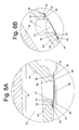
- FIG. 5A is a greatly enlarged sectional view of another exemplary embodiment of a vent assembly, e.g., a gas permeable member disposed over a vent hole, constructed in accordance with this invention and shown within the circular area designated 4 A- 6 B in FIG. 3 ;
- a vent assembly e.g., a gas permeable member disposed over a vent hole, constructed in accordance with this invention and shown within the circular area designated 4 A- 6 B in FIG. 3 ;
- FIG. 5B is an isometric view of the portion of the vent assembly shown in FIG. 5A ;
- FIG. 6A is a greatly enlarged sectional view of another exemplary embodiment of a vent assembly, e.g., a one-way valve disposed over a vent hole, constructed in accordance with this invention and shown within the circular area designated 4 A- 6 B in FIG. 3 ; and
- FIG. 6B is an isometric view of the portion of the vent assembly shown in FIG. 6A .
- FIGS. 1 , 2 and 3 one exemplary embodiment of an insulated container which is constructed in accordance with this invention. It must be pointed out at this juncture that the container 20 is merely illustrative of numerous double walled container products that make use of a pair of vessels separated by an insulating space to provide thermal insulation for the inner vessel.
- the double walled container 20 is best seen in FIGS. 1-3 and basically comprises an assembly of a hollow outer body or vessel 22 , a hollow inner liner or vessel 24 , a lid assembly 26 and a vent assembly 28 .
- the outer vessel 22 is a hollow member which is formed, e.g., blow molded, of a plastic, e.g., thermoplastic, material.
- the hollow inner vessel 24 is also formed, e.g., blow molded, of a plastic material.
- the material of the inner vessel may be the same plastic material as the outer vessel 22 or some other material.
- the inner vessel 24 is disposed within the outer vessel 22 . When so located they are separated from each other by an insulating space 30 . That space is arranged to be under some vacuum.
- the inner vessel 24 of the container is thermally insulated from the ambient atmosphere.
- the inner vessel 24 is arranged to receive any type of liquid, e.g., cold water or soda, hot tea or coffee, etc., to maintain its temperature.
- the lid assembly 26 which will be described later is arranged to be opened to provide access to the contents of the container held within the inner vessel. This enables the user to fill the container with some liquid when desired and to remove, e.g., drink or pour, the contents the container when desired.
- vent assembly 28 of this invention can take various forms. Two of the exemplary forms are such that any air or other gas that may be in the insulation space can vent out of that space through a vent hole 32 (FIGS. 3 and 4 A- 6 B) in the outer vessel 22 when the container is subjected to high heat (such as could occur when it is being washed in a dishwasher). Two of the exemplary forms are such that liquid is prevented from entering through the vent hole into the interior of the insulating space.
- the vent assembly 28 comprises a one-way valve and a gas permeable cover disposed over the vent hole 32 .
- the vent assembly comprises a gas permeable cover disposed over the vent hole 32 to prevent the ingress of water or other liquids into the insulating space.
- the vent assembly comprises a one-way valve disposed over the vent hole 32 to allow gases to vent out of the insulating space when the container is subjected to high heat, such as when the container is placed within a dishwasher to clean it.
- the inner vessel 24 is disposed within the outer vessel 22 .
- the two vessels are bonded together, e.g., and ultrasonically welded, to form a unitary double walled container having the insulating space 30 located between the walls of the two vessels.
- the inner vessel includes a flange 34 which serves the purpose of supporting the inner vessel on a flange 36 of the outer vessel during that ultrasonic welding.
- the flanges 34 and 36 are constructed in accordance with the teachings in U.S. Provisional Application Ser. No. 61/567234, filed on Dec.
- the outer vessel includes a generally cylindrical sidewall 38 , and a somewhat concave bottom wall 40 having a central depression 42 .
- the flange 36 is located at the top end of the sidewall 38 and includes an annular wall projecting up from the top surface of the flange.
- the inner vessel 24 includes a generally cylindrical sidewall 44 and a slightly concave bottom wall 46 .
- the top end portion of the sidewall 44 includes the heretofore identified flange 34 , which projects radially outwardly from that sidewall.
- the flange 34 includes an engagement surface in the form of an annular recess or groove extending into the undersurface of that flange.
- the undersurface of the flange 34 is of a complementary shape to that of the flange 36 to receive the flange therein, with the upstanding annular wall of the flange 36 received within the annular groove in the flange 34 .
- This arrangement forms a tongue and groove interference (or double shear) joint, which is suitable for concentrating ultrasonic welding energy thereat.
- the lid assembly is also formed of a plastic material (which can be the same or a different material from the material(s) forming the outer vessel 22 and the inner vessel 24 ) or of any other material. It includes a ring portion 48 and a cap portion 50 .
- the ring portion includes a top wall 52 and a peripheral sidewall 54 .
- the sidewall 54 includes internal threads which are arranged to be threadedly connected (screwed onto) a correspondingly externally threaded cylindrical portion extending upward from the top of the inner vessel 24 .
- the cap portion 50 is a hollow member which is arranged to cover or seal off the interior of the bottle, i.e., the inner vessel 24 .
- the cap portion is connected to the ring portion by a hinge 58 ( FIGS. 1 and 2 ) so that it can pivoted downward into engagement with the ring portion 48 , whereupon its lower peripheral edge 60 engages an annular ledge extending about the periphery of the top wall 52 as shown in FIG. 3 .
- the center of the top wall 52 is in the form of a tapering hollow spout, through which the contents of the inner vessel can be accessed when the cap portion 50 is pivoted upward and backward. This feature enables one to readily fill the vessel 24 or to drink from the vessel.
- a clasp or latch 64 ( FIGS. 1 and 2 ) are provided on the cap portion 50 to engage the ring portion 48 to hold the cap portion in the closed position, like shown in FIG. 1 , to thereby close off the interior of the container.
- That assembly comprises a one-way valve and a gas permeable cover.
- the hole 32 is in the form of an aperture in the bottom wall 40 of the outer vessel that is in fluid communication with the insulating space 30 .
- the bottom surface of the bottom wall 40 contiguous with the hole 32 is planar and forms the valve seat 66 for the one-way, check valve of this embodiment.
- a portion of the bottom wall 40 just outside the valve seat is relieved to form an annular recess or groove 68 surrounding the valve seat.
- An elastomeric, e.g., rubber, disc 70 is disposed over the vent hole 32 and is of sufficient size that the portion of its upper surface that is contiguous with its outer periphery abuts the planar valve seat 66 .
- the disk 70 forms the valve member or element of the one-way, check valve.
- the elastomeric disc is adhesively secured via a layer of adhesive 72 to a disc of material 74 making up the gas permeable cover.
- the cover 74 is formed of a membrane material that allows passage of gas but not liquids or other contaminants therethrough.
- the material can be any suitable commercially available material, such as GORE-TEX® GAW 112 waterproof/breathable fabric available from W. L.
- the gas permeable membrane disc 74 is in turn adhesively secured to the bottom surface of the bottom wall of the outer vessel 22 outside the annular groove 68 by a ring of adhesive 76 to hold the valve element 70 in normal engagement with the valve seat.
- the rubber disc 70 is compressed to tension the membrane 74 .
- the valve seat and the membrane bond area are stepped as shown to develop proper tension. This arrangement serves to act as the spring to maintain the one-way valve seal in it normally closed condition as shown in FIGS. 4A and 4B .
- the increased pressure in any residual air within the space 30 will cause the valve member 70 to move off of the valve seat 66 , whereupon that air will be able to pass through the interface between the valve seat and the valve element into the annular groove 68 and out to the ambient atmosphere through the underlying portion of the membrane 74 .
- the membrane being gas permeable, but liquid impermeable prevents any liquids from gaining ingress into the insulating space while the valve member 70 is open (i.e., off of the valve seat).
- the pressure within the insulating space 30 begins to equalize, whereupon when a predetermined pressure is reached the valve member 70 reseats itself on the valve seat 66 , thereby closing the valve. Further cooling of the container, with the valve closed, prevents any additional air from gaining ingress into the insulating space 30 , thereby automatically recharging the vacuum therein.
- the vacuum is recharged each time that the container is run through a dishwasher. Minor leakage through the seals or the permeability of the container material does not matter since the vacuum is recharged.
- FIGS. 5A and 5B the details of the vent assembly 28 that is in the form of a gas permeable cover disposed over the vent hole 32 will now be discussed. That vent assembly does not include a check valve. However, since the vent includes a gas permeable membrane the pressure within the space 30 will always be equalized to the ambient atmospheric pressure surrounding the outer member. Thus, the embodiment of FIGS. 5A and 5B prevents the build up of pressure when the container is subjected to heat, such as occurs when it is washed in a dishwasher. Moreover, since the membrane is gas permeable, but liquid impermeable, it precludes liquids or other contaminants from entering into the insulating space 30 . Since the embodiment of FIGS.
- the bottom surface of the bottom wall of the outer vessel 22 need not be constructed to include a valve seat 66 and contiguous annular groove 68 , as was the case with the embodiment of the vent assembly shown in FIGS. 4A and 4B .
- the bottom wall of the outer vessel 22 which is now designated by the reference number 40 ′, includes a generally planar surface 78 contiguous with the hole 32 .
- a disc 80 of a membrane material that allows passage of gas but not liquids or other contaminants therethrough, like that making up disc 74 is adhesively secured via a ring of adhesive 82 to the planar surface 78 .
- vent assembly 28 that is in the form of a one-way check valve disposed over the vent hole 32 will now be discussed. That vent assembly does not include a gas permeable membrane. Thus, it does not preclude the ingress of liquid into the valve at all times like the embodiments of FIGS. 4A , 4 B, and FIGS. 5A and 5B .
- the bottom surface of the bottom wall of the outer vessel 22 which is now designated by the reference number 40 ′′, includes a generally planar surface contiguous with the hole 32 . That surface forms the valve seat 84 for the one-way valve of this embodiment.
- a portion of the bottom wall 40 ′′ just outside the valve seat 84 is relieved to form an annular recess or groove 86 surrounding the valve seat.
- Another annular planar portion 88 of the bottom wall 40 is located just outside the annular groove 86 .
- the planar surface of portion 88 is in a plane slightly higher than the plane of the valve seat 84 .
- An elastomeric, e.g., rubber, disc 90 is disposed over the vent hole 32 and is of sufficient size and the upper surface contiguous with its central portion is planar so that it abuts the valve seat 84 .
- the upper surface of the portion 92 of the disc 90 contiguous with its periphery is also planar and is disposed in a plane above the plane of the surface which engages the valve seat.
- the portion 92 of the disc 90 is adhesively secured to the surface 88 via a layer of adhesive 94 .
- the disc 90 forms the valve member or element of the one-way check valve of this embodiment.
- a plurality of equidistantly spaced apertures 96 are provided in the disc 90 close to its outer periphery and such that when the disc is secured to the bottom wall 40 ′′ the apertures 96 are aligned with the annular groove 86 .
- the rubber disc 90 is tensioned.
- the stepped shape of the valve seat 84 and the area 88 to which the disc is secured develops the proper tension and that combination serves to act as the spring to maintain the one-way valve seal.
- valve member 90 In operation the valve member 90 is normal seated on the valve seat to close off the vent hole 32 .
- excess pressure within the vacuum space 30 such as could occur when the container is subjected to high heat during washing in a dishwasher, the increased pressure in any residual air within the space 30 will cause the valve member 90 to move off of the valve seat 84 , whereupon that air will be able to pass through the interface between the valve seat and the valve element into the annular groove 86 and out to the ambient atmosphere through the apertures 96 in the valve member.
- vent assemblies shown and described herein represent but a few of a myriad of assemblies that can be constructed in accordance with this invention to achieve the ends of this invention. Thus, those embodiments are not to be deemed limiting.
- the materials making up the vent assemblies can be selected as appropriate. Thus, the examples of the materials given are also not limiting.
- the details regarding the construction and arrangement of the container itself, e.g., its walls, insulating space, lid, etc., as described above are merely exemplary of various arrangements and constructions that containers in accordance with this invention can take. Accordingly, the details of the container and its lid as described above are not limiting.
Abstract
Description
Claims (12)
Priority Applications (1)
| Application Number | Priority Date | Filing Date | Title |
|---|---|---|---|
| US13/401,031 US9254063B2 (en) | 2012-02-21 | 2012-02-21 | Double walled insulated container with rechargeable vacuum |
Applications Claiming Priority (1)
| Application Number | Priority Date | Filing Date | Title |
|---|---|---|---|
| US13/401,031 US9254063B2 (en) | 2012-02-21 | 2012-02-21 | Double walled insulated container with rechargeable vacuum |
Publications (2)
| Publication Number | Publication Date |
|---|---|
| US20130213978A1 US20130213978A1 (en) | 2013-08-22 |
| US9254063B2 true US9254063B2 (en) | 2016-02-09 |
Family
ID=48981495
Family Applications (1)
| Application Number | Title | Priority Date | Filing Date |
|---|---|---|---|
| US13/401,031 Expired - Fee Related US9254063B2 (en) | 2012-02-21 | 2012-02-21 | Double walled insulated container with rechargeable vacuum |
Country Status (1)
| Country | Link |
|---|---|
| US (1) | US9254063B2 (en) |
Cited By (14)
| Publication number | Priority date | Publication date | Assignee | Title |
|---|---|---|---|---|
| US20180282051A1 (en) * | 2017-03-29 | 2018-10-04 | WAITR, Inc. | Insulated container with tamper-evident, removable, and resealable lid |
| CN108852049A (en) * | 2018-07-18 | 2018-11-23 | 夏静 | A kind of anti-thermos flask pushed over |
| USD839054S1 (en) | 2017-08-17 | 2019-01-29 | Yeti Coolers, Llc | Container |
| USD839055S1 (en) | 2017-08-17 | 2019-01-29 | Yeti Coolers, Llc | Container |
| USD839056S1 (en) | 2017-08-17 | 2019-01-29 | Yeti Coolers, Llc | Container |
| USD856748S1 (en) | 2017-08-17 | 2019-08-20 | Yeti Coolers, Llc | Lid |
| USD878166S1 (en) | 2018-04-11 | 2020-03-17 | Yeti Coolers, Llc | Container |
| USD878163S1 (en) | 2018-04-11 | 2020-03-17 | Yeti Coolers, Llc | Container |
| USD885903S1 (en) | 2018-04-11 | 2020-06-02 | Yeti Coolers, Llc | Lid |
| USD887793S1 (en) | 2018-04-11 | 2020-06-23 | Yeti Coolers, Llc | Container |
| USD888508S1 (en) | 2018-04-11 | 2020-06-30 | Yeti Coolers, Llc | Container |
| USD888509S1 (en) | 2018-04-11 | 2020-06-30 | Yeti Coolers, Llc | Container |
| US10940227B2 (en) * | 2014-08-19 | 2021-03-09 | Zobele Espana, S. A. | Device for evaporating volatile substances |
| US10968029B1 (en) | 2017-08-17 | 2021-04-06 | Yeti Coolers, Llc | Container and lid |
Families Citing this family (31)
| Publication number | Priority date | Publication date | Assignee | Title |
|---|---|---|---|---|
| US20130221013A1 (en) * | 1997-04-07 | 2013-08-29 | J. Bruce Kolowich | Thermal receptacle with phase change material |
| US9145996B2 (en) * | 2013-08-13 | 2015-09-29 | Joseph Alexander MENDEZ | Lower extremity dryer |
| US9555948B2 (en) | 2013-12-09 | 2017-01-31 | Rubbermaid Incorporated | Double-walled, vacuum-insulated container having inner coating cured at high temperature |
| US9801492B1 (en) | 2014-02-18 | 2017-10-31 | Shin-Shuoh Lin | Liquid container with interchangeable attachments |
| JP6427675B2 (en) * | 2014-12-19 | 2018-11-21 | ダウ グローバル テクノロジーズ エルエルシー | Vacuum vessel |
| US9675212B2 (en) | 2015-02-03 | 2017-06-13 | Sharkninja Operating Llc | Container for food processing system |
| USD783355S1 (en) | 2015-07-17 | 2017-04-11 | Sharkninja Operating Llc | Blender attachment |
| USD804905S1 (en) | 2015-08-31 | 2017-12-12 | Yeti Coolers, Llc | Container |
| USD751338S1 (en) | 2015-11-04 | 2016-03-15 | Yeti Coolers, Llc | Lid |
| USD808218S1 (en) | 2015-08-31 | 2018-01-23 | Yeti Coolers, Llc | Container |
| US10034580B2 (en) * | 2015-10-05 | 2018-07-31 | Yeti Coolers, Llc | Container and handle and method of forming a container and handle |
| US10232992B2 (en) | 2015-10-30 | 2019-03-19 | Yeti Coolers, Llc | Closure and lid and method of forming closure and lid |
| US10232993B2 (en) | 2015-10-30 | 2019-03-19 | Yeti Coolers, Llc | Closure and lid and method of forming closure and lid |
| EP3367850B1 (en) | 2015-10-30 | 2022-05-11 | Yeti Coolers, LLC | Closure and lid and method of forming closure and lid |
| CN108495795B (en) | 2015-11-25 | 2021-01-15 | 野醍冷却器有限责任公司 | Insulated container with vacuum insulated panel and method |
| JP6135747B2 (en) * | 2015-12-04 | 2017-05-31 | タイガー魔法瓶株式会社 | Vacuum double container for soup insulation |
| USD791543S1 (en) | 2016-04-14 | 2017-07-11 | Silver Buffalo, LLC | Tumbler |
| USD815893S1 (en) | 2016-10-07 | 2018-04-24 | Yeti Coolers, Llc | Lid |
| USD824212S1 (en) | 2016-10-07 | 2018-07-31 | Yeti Coolers, Llc | Lid |
| JP6481674B2 (en) * | 2016-11-18 | 2019-03-13 | トヨタ自動車株式会社 | Vacuum insulated container |
| USD821824S1 (en) | 2017-05-16 | 2018-07-03 | Yeti Coolers, Llc | Insulating device |
| USD827379S1 (en) | 2017-05-24 | 2018-09-04 | The Boeing Company | Tumbler |
| USD827378S1 (en) | 2017-05-24 | 2018-09-04 | The Boeing Company | Tumbler |
| USD845064S1 (en) | 2017-05-24 | 2019-04-09 | Silver Buffalo, LLC | Tumbler lid |
| US11172784B2 (en) * | 2017-06-08 | 2021-11-16 | Leapfrog Product Development LLC | Dual removable end cap vessel |
| WO2020086567A1 (en) | 2018-10-23 | 2020-04-30 | Yeti Coolers, Llc | Closure and lid and method of forming closure and lid |
| USD982973S1 (en) | 2019-10-09 | 2023-04-11 | Yeti Coolers, Llc | Tumbler |
| USD964102S1 (en) | 2019-10-09 | 2022-09-20 | Yeti Coolers, Llc | Tumbler |
| USD977912S1 (en) | 2020-10-01 | 2023-02-14 | Yeti Coolers, Llc | Tumbler |
| USD982982S1 (en) | 2020-10-01 | 2023-04-11 | Yeti Coolers, Llc | Tumbler |
| US11827411B1 (en) * | 2021-10-28 | 2023-11-28 | Miguel Rosas | Beverage bottle with removable bottom |
Citations (9)
| Publication number | Priority date | Publication date | Assignee | Title |
|---|---|---|---|---|
| US723796A (en) * | 1903-01-19 | 1903-03-24 | Frank Leslie Williams | Shaker or mixer. |
| US2981430A (en) * | 1959-04-21 | 1961-04-25 | Hsue C Tsien | Plastic vacuum containers |
| US3863794A (en) * | 1973-04-11 | 1975-02-04 | Brighton Corp Ltd | Vacuum retaining jar |
| US4782670A (en) * | 1988-03-10 | 1988-11-08 | Long Timothy S | Dual hot-cold maintenance container |
| US6601720B2 (en) * | 2000-09-28 | 2003-08-05 | Gerber Products Company | Nursing bottle |
| US6789393B2 (en) * | 2002-02-11 | 2004-09-14 | S.C. Johnson Home Storage, Inc. | Container with pressure relief and lid and method of manufacture therefor |
| US20060000733A1 (en) * | 2004-07-02 | 2006-01-05 | Albritton Charles W | Rigid container with vacuum channel walls |
| US20070114485A1 (en) * | 2003-07-29 | 2007-05-24 | Societe Bic | Fuel Cartridge with Flexible Liner |
| US20100200599A1 (en) * | 2009-02-10 | 2010-08-12 | Robert Molthen | Vacuum insulated container |
-
2012
- 2012-02-21 US US13/401,031 patent/US9254063B2/en not_active Expired - Fee Related
Patent Citations (9)
| Publication number | Priority date | Publication date | Assignee | Title |
|---|---|---|---|---|
| US723796A (en) * | 1903-01-19 | 1903-03-24 | Frank Leslie Williams | Shaker or mixer. |
| US2981430A (en) * | 1959-04-21 | 1961-04-25 | Hsue C Tsien | Plastic vacuum containers |
| US3863794A (en) * | 1973-04-11 | 1975-02-04 | Brighton Corp Ltd | Vacuum retaining jar |
| US4782670A (en) * | 1988-03-10 | 1988-11-08 | Long Timothy S | Dual hot-cold maintenance container |
| US6601720B2 (en) * | 2000-09-28 | 2003-08-05 | Gerber Products Company | Nursing bottle |
| US6789393B2 (en) * | 2002-02-11 | 2004-09-14 | S.C. Johnson Home Storage, Inc. | Container with pressure relief and lid and method of manufacture therefor |
| US20070114485A1 (en) * | 2003-07-29 | 2007-05-24 | Societe Bic | Fuel Cartridge with Flexible Liner |
| US20060000733A1 (en) * | 2004-07-02 | 2006-01-05 | Albritton Charles W | Rigid container with vacuum channel walls |
| US20100200599A1 (en) * | 2009-02-10 | 2010-08-12 | Robert Molthen | Vacuum insulated container |
Cited By (16)
| Publication number | Priority date | Publication date | Assignee | Title |
|---|---|---|---|---|
| US10940227B2 (en) * | 2014-08-19 | 2021-03-09 | Zobele Espana, S. A. | Device for evaporating volatile substances |
| US20180282051A1 (en) * | 2017-03-29 | 2018-10-04 | WAITR, Inc. | Insulated container with tamper-evident, removable, and resealable lid |
| US11091310B2 (en) * | 2017-03-29 | 2021-08-17 | WAITR, Inc. | Insulated container with tamper-evident, removable, and resealable lid |
| USD839056S1 (en) | 2017-08-17 | 2019-01-29 | Yeti Coolers, Llc | Container |
| USD839055S1 (en) | 2017-08-17 | 2019-01-29 | Yeti Coolers, Llc | Container |
| USD856748S1 (en) | 2017-08-17 | 2019-08-20 | Yeti Coolers, Llc | Lid |
| USD839054S1 (en) | 2017-08-17 | 2019-01-29 | Yeti Coolers, Llc | Container |
| US10968029B1 (en) | 2017-08-17 | 2021-04-06 | Yeti Coolers, Llc | Container and lid |
| USD878166S1 (en) | 2018-04-11 | 2020-03-17 | Yeti Coolers, Llc | Container |
| USD878163S1 (en) | 2018-04-11 | 2020-03-17 | Yeti Coolers, Llc | Container |
| USD885903S1 (en) | 2018-04-11 | 2020-06-02 | Yeti Coolers, Llc | Lid |
| USD887793S1 (en) | 2018-04-11 | 2020-06-23 | Yeti Coolers, Llc | Container |
| USD888508S1 (en) | 2018-04-11 | 2020-06-30 | Yeti Coolers, Llc | Container |
| USD888509S1 (en) | 2018-04-11 | 2020-06-30 | Yeti Coolers, Llc | Container |
| CN108852049B (en) * | 2018-07-18 | 2021-06-15 | 陈山 | Thermos flask capable of preventing being pushed down |
| CN108852049A (en) * | 2018-07-18 | 2018-11-23 | 夏静 | A kind of anti-thermos flask pushed over |
Also Published As
| Publication number | Publication date |
|---|---|
| US20130213978A1 (en) | 2013-08-22 |
Similar Documents
| Publication | Publication Date | Title |
|---|---|---|
| US9254063B2 (en) | Double walled insulated container with rechargeable vacuum | |
| US10717567B2 (en) | Discharge container | |
| JP5667655B2 (en) | Beverage container | |
| JP5096333B2 (en) | Beverage supply system and beverage container | |
| US9642482B2 (en) | Portable beverage container with ultrasonic welded joint and method of making the same | |
| US20130175234A1 (en) | Portable beverage container with self opening hinged lid | |
| KR20170005451A (en) | Mixing/closure device for a container | |
| KR20000005798A (en) | Drinking Receptacle | |
| JP2017511237A (en) | Beverage container in which beverage is injected through the bottom | |
| US20190135502A1 (en) | Vacuum insulated beverage container with removable cup and method of using the same | |
| CN103328340A (en) | A method for producing filled and reclosable pressure vessels | |
| US20210323737A1 (en) | Lidded container | |
| JP2018517623A (en) | Beverage supply device and beverage supply device assembly | |
| US7967163B1 (en) | Pre-filled disposable container | |
| KR102376066B1 (en) | Vacuum sealed lead inserts for insulated containers | |
| CN109561755B (en) | Package for packaging products, in particular cosmetic ingredients | |
| US9877606B2 (en) | Tea infuser | |
| US20110042374A1 (en) | Drink cup | |
| JP2017178387A (en) | Bottle cap for water server | |
| KR101560679B1 (en) | A Heat Reserving Pot | |
| US20200223603A1 (en) | Food jar and methods of making and using same | |
| JP2015136475A (en) | Food warming container | |
| KR101453169B1 (en) | Bottle cap for carbonated beverage | |
| KR101450574B1 (en) | Food container | |
| KR200478706Y1 (en) | Check valve for food container |
Legal Events
| Date | Code | Title | Description |
|---|---|---|---|
| AS | Assignment |
Owner name: HELLO NEW PRODUCTS, LLC, OHIO Free format text: ASSIGNMENT OF ASSIGNORS INTEREST;ASSIGNORS:LIBOUREL, CHARLES;SIMONELLI, JAMES K.;SIGNING DATES FROM 20120206 TO 20120302;REEL/FRAME:027810/0313 |
|
| AS | Assignment |
Owner name: TERVIS TUMBLER COMPANY, FLORIDA Free format text: ASSIGNMENT OF ASSIGNORS INTEREST;ASSIGNOR:HELLO NEW PRODUCTS, LLC;REEL/FRAME:027825/0656 Effective date: 20120307 |
|
| ZAAA | Notice of allowance and fees due |
Free format text: ORIGINAL CODE: NOA |
|
| ZAAB | Notice of allowance mailed |
Free format text: ORIGINAL CODE: MN/=. |
|
| STCF | Information on status: patent grant |
Free format text: PATENTED CASE |
|
| MAFP | Maintenance fee payment |
Free format text: PAYMENT OF MAINTENANCE FEE, 4TH YEAR, LARGE ENTITY (ORIGINAL EVENT CODE: M1551); ENTITY STATUS OF PATENT OWNER: LARGE ENTITY Year of fee payment: 4 |
|
| FEPP | Fee payment procedure |
Free format text: MAINTENANCE FEE REMINDER MAILED (ORIGINAL EVENT CODE: REM.); ENTITY STATUS OF PATENT OWNER: LARGE ENTITY |
|
| LAPS | Lapse for failure to pay maintenance fees |
Free format text: PATENT EXPIRED FOR FAILURE TO PAY MAINTENANCE FEES (ORIGINAL EVENT CODE: EXP.); ENTITY STATUS OF PATENT OWNER: LARGE ENTITY |
|
| STCH | Information on status: patent discontinuation |
Free format text: PATENT EXPIRED DUE TO NONPAYMENT OF MAINTENANCE FEES UNDER 37 CFR 1.362 |