EP3323731A1 - Elevator system for auxiliary power unit - Google Patents
Elevator system for auxiliary power unit Download PDFInfo
- Publication number
- EP3323731A1 EP3323731A1 EP16199282.1A EP16199282A EP3323731A1 EP 3323731 A1 EP3323731 A1 EP 3323731A1 EP 16199282 A EP16199282 A EP 16199282A EP 3323731 A1 EP3323731 A1 EP 3323731A1
- Authority
- EP
- European Patent Office
- Prior art keywords
- bar
- terminal
- elevator system
- order
- motors
- Prior art date
- Legal status (The legal status is an assumption and is not a legal conclusion. Google has not performed a legal analysis and makes no representation as to the accuracy of the status listed.)
- Granted
Links
Images


Classifications
-
- B—PERFORMING OPERATIONS; TRANSPORTING
- B66—HOISTING; LIFTING; HAULING
- B66F—HOISTING, LIFTING, HAULING OR PUSHING, NOT OTHERWISE PROVIDED FOR, e.g. DEVICES WHICH APPLY A LIFTING OR PUSHING FORCE DIRECTLY TO THE SURFACE OF A LOAD
- B66F11/00—Lifting devices specially adapted for particular uses not otherwise provided for
- B66F11/04—Lifting devices specially adapted for particular uses not otherwise provided for for movable platforms or cabins, e.g. on vehicles, permitting workmen to place themselves in any desired position for carrying out required operations
-
- B—PERFORMING OPERATIONS; TRANSPORTING
- B60—VEHICLES IN GENERAL
- B60P—VEHICLES ADAPTED FOR LOAD TRANSPORTATION OR TO TRANSPORT, TO CARRY, OR TO COMPRISE SPECIAL LOADS OR OBJECTS
- B60P1/00—Vehicles predominantly for transporting loads and modified to facilitate loading, consolidating the load, or unloading
- B60P1/02—Vehicles predominantly for transporting loads and modified to facilitate loading, consolidating the load, or unloading with parallel up-and-down movement of load supporting or containing element
-
- B—PERFORMING OPERATIONS; TRANSPORTING
- B64—AIRCRAFT; AVIATION; COSMONAUTICS
- B64D—EQUIPMENT FOR FITTING IN OR TO AIRCRAFT; FLIGHT SUITS; PARACHUTES; ARRANGEMENT OR MOUNTING OF POWER PLANTS OR PROPULSION TRANSMISSIONS IN AIRCRAFT
- B64D41/00—Power installations for auxiliary purposes
-
- B—PERFORMING OPERATIONS; TRANSPORTING
- B64—AIRCRAFT; AVIATION; COSMONAUTICS
- B64F—GROUND OR AIRCRAFT-CARRIER-DECK INSTALLATIONS SPECIALLY ADAPTED FOR USE IN CONNECTION WITH AIRCRAFT; DESIGNING, MANUFACTURING, ASSEMBLING, CLEANING, MAINTAINING OR REPAIRING AIRCRAFT, NOT OTHERWISE PROVIDED FOR; HANDLING, TRANSPORTING, TESTING OR INSPECTING AIRCRAFT COMPONENTS, NOT OTHERWISE PROVIDED FOR
- B64F5/00—Designing, manufacturing, assembling, cleaning, maintaining or repairing aircraft, not otherwise provided for; Handling, transporting, testing or inspecting aircraft components, not otherwise provided for
- B64F5/10—Manufacturing or assembling aircraft, e.g. jigs therefor
-
- B—PERFORMING OPERATIONS; TRANSPORTING
- B64—AIRCRAFT; AVIATION; COSMONAUTICS
- B64F—GROUND OR AIRCRAFT-CARRIER-DECK INSTALLATIONS SPECIALLY ADAPTED FOR USE IN CONNECTION WITH AIRCRAFT; DESIGNING, MANUFACTURING, ASSEMBLING, CLEANING, MAINTAINING OR REPAIRING AIRCRAFT, NOT OTHERWISE PROVIDED FOR; HANDLING, TRANSPORTING, TESTING OR INSPECTING AIRCRAFT COMPONENTS, NOT OTHERWISE PROVIDED FOR
- B64F5/00—Designing, manufacturing, assembling, cleaning, maintaining or repairing aircraft, not otherwise provided for; Handling, transporting, testing or inspecting aircraft components, not otherwise provided for
- B64F5/50—Handling or transporting aircraft components
-
- B—PERFORMING OPERATIONS; TRANSPORTING
- B66—HOISTING; LIFTING; HAULING
- B66F—HOISTING, LIFTING, HAULING OR PUSHING, NOT OTHERWISE PROVIDED FOR, e.g. DEVICES WHICH APPLY A LIFTING OR PUSHING FORCE DIRECTLY TO THE SURFACE OF A LOAD
- B66F7/00—Lifting frames, e.g. for lifting vehicles; Platform lifts
- B66F7/10—Lifting frames, e.g. for lifting vehicles; Platform lifts with platforms supported directly by jacks
- B66F7/12—Lifting frames, e.g. for lifting vehicles; Platform lifts with platforms supported directly by jacks by mechanical jacks
- B66F7/14—Lifting frames, e.g. for lifting vehicles; Platform lifts with platforms supported directly by jacks by mechanical jacks screw operated
-
- B—PERFORMING OPERATIONS; TRANSPORTING
- B64—AIRCRAFT; AVIATION; COSMONAUTICS
- B64D—EQUIPMENT FOR FITTING IN OR TO AIRCRAFT; FLIGHT SUITS; PARACHUTES; ARRANGEMENT OR MOUNTING OF POWER PLANTS OR PROPULSION TRANSMISSIONS IN AIRCRAFT
- B64D41/00—Power installations for auxiliary purposes
- B64D2041/002—Mounting arrangements for auxiliary power units (APU's)
Definitions
- the present invention pertains to the aeronautical field, and relates to an elevator system to position element structure in order to facilitate its integration inside an aircraft.
- the invention is intended for the installation of the auxiliary power unit ("APU") and the ancillary elements inside the housing of the tail cone of an aircraft.
- APU auxiliary power unit
- the rear fuselage 120 of an aircraft 110 house at least one Auxiliary Power Unit (APU) 122.
- the APU 122 is a gas turbine which is used in aircraft 110 in order to provide solely electric, or pneumatic, or hydraulic power, or any combination of these powers used simultaneously.
- the APU 122 serves for the following main functions:
- the APU 122 Due to the APU 122 being a possible fire focal point, the current trend among most manufacturers is that the APU 122 has to be located in the tail cone 121, as above mentioned, in order to protect the rest of the aircraft fuselage 130. In order to do that the APU compartment is separated to the rest of fuselage via a bulkhead firewall 123.
- the support system of APU 122 comprises a frame of rods or bars secured directly to the semi-single-hull structure of the tail cone 121.
- the support system 124 will be represented only in figure 2 , but its presence is indispensable to support safely the APU 122.
- the existing fish pole systems 140 usually need at least two operators using respectively the control system 141, 142, to install the APU 122 in the APU compartment 126.
- the using of fish pole systems 140 can be dangerous.
- the APU 122 can fall down at least on one of the operators and can risk to injure them in the best case, but sometime can kill in the worst case.
- the present invention is defined in the attached independent and dependent claims, and is based on an elevator system which allows to the APU to be raised from the ground or a platform, to be housed inside the APU compartment in the tail cone of the aircraft.
- a first object of the invention is relative to an elevator system in order to proceed to the installation of a heavy load in its housing inside an aircraft compartment via a narrow door located on the underneath of the said aircraft, comprising:
- the terminal is able to be fixed and/or mobile from the support;
- the attachment means comprise:
- the expandable means is able to fit to the hole of the end of the upper bar, such as to allow to the bar to turn freely and avoid to the aircraft structure to support the weight of the load; In an embodiment of the invention the expandable means is able to support a weight of the load superior to 1000 kg;
- a second object of the invention is relative to a process to manage the wireless synchronization phase of the different motors of the elevator system wherein, the terminal apply the following steps:
- a third object of the invention is relative to a process to manage the wireless communication to control the different motors of the wheel in order to interact on the direction, orientation, velocity, and brake system, wherein the terminal apply the following steps:
- a fourth object of the invention is relative to a process to control and regulate the velocity to up or down the load, wherein the terminal apply the following steps:
- a fifth object of the invention is relative to a process to proceed to different sequences of shut down of the elevator system, wherein the terminal apply the following steps:
- the present invention is directed generally toward elevator systems for auxiliary power unit (“APU”), and associated systems.
- a person skilled in the relevant art will understand, however, that the invention may have additional embodiments, and that the invention may be practiced without several of the details of the embodiments described below with reference to figures 4-6f .
- the invention proposes the using of an elevator system 400 in order to replace the fish pole system 140 of the state of art.
- the elevator system 400 comprises a support 410 on which the APU 122 is put down on its upper surface 411.
- the support 410 is mounted on a set of wheels 413 or equivalent means, in order to move easily the APU 122.
- the set of wheels 413 is able to move via a manual traction of the support 410 or via a set of electric motor with control unit able to be managed by a terminal.
- This terminal is able to be fixed and/or mobile from the support 410. The working of this terminal, its different modes of use and interaction with the elevator system 400 will be explain more in details during the rest of the description.
- the upper surface 411 of the support 410 comprise some attachments point in order to fasten at least two base elements 420 rigidly on the support 410.
- Each base element 420 as shown in detail in figure 6a , comprises an electric motor comprising a stator 421 fixed to the support 410 and a rotor fixed on a circular plate 422.
- Each circular plate 422 comprises firmly on its upper surface 423 two parallel connecting rods 424.
- the connecting rods 424 comprise respectively a hole 425, such as both of the hole 425 are able to receive a through bolt 426.
- the through bolt 426 is able to be closed at the end with a nut 427.
- the elevator system 400 comprises also a bar 450 comprising a lower bar 460, a standard bar 470 and an upper bar 480.
- a bar 450 comprising a lower bar 460, a standard bar 470 and an upper bar 480.
- the upper bar comprises respectively two ends 481, 482, where the end 481 comprises a hole 483 fit to be able to receive an attachment means 484, as shown in figure 6c .
- This attachment means 484 comprises a fixation means 485, such as a fitting bolt, in order to fixate the elevator system 400 via the upper bar 480 to the structure of the APU compartment 126.
- the attachment means 484 comprises also an expandable means 486, such as a spring system for example.
- the expandable means 486 is fitted in order to adjust the length of the bar 450 and fits the distance between the upper bar 480 and the upper surface 411 of the support 410.
- the expandable means 486 is able to fit to the hole 483 of the end 481 of the upper bar 480, such as to allow to the bar 450 to turn freely and avoid to the aircraft structure, and particularly the tail cone part to support the weight of the APU or any load. In order to reach this objective, the expandable means 486 is able to support load superior to 1000kg.
- the end 482 of the upper bar 480 comprises a hole 487 able to receive a fitting bolt 473 from a standard bar 470.
- each standard bar 470 comprises respectively two ends 471, 472, where a first end 471 comprises a fitting bolt 473 able to screw respectively inside the fitting hole 487, 474 of the upper bar 480 or of a standard bar 470, and where the end 472 comprises a fitting hole 474 able to receive a fitting bolt 473 from standard bar 470 or a fitting bolt 463 from lower bar 460.
- Each lower bar 460 comprises respectively two ends 461, 462.
- a first end 461 comprises a fitting bolt 463 able to screw inside a fitting hole 474 of the standard bar 470 or the fitting hole 487 of the upper bar 480, and where the second end 462 comprises a through bore 464 able to receive the through bolt 426.
- Each upper bar 480, standard bar 470 or lower bar 460 is defined as being a metallic cylinder with a radius R and a height H, such as the radius R is defined sufficiently to support the weight W of the APU according the final height of the bar 450.
- the lower bar 460 comprise at its end 462 a flat circular base 465 able to fit between the connecting rods 424. For that, the distance between the connecting rods 420 is 2R.
- the flat circular base 465 allows to avoid the articulation of the bar 450 on the axis X, and the bolt 426 going through respectively the hole 425 and 464 as shown in figure 6e , for connecting the bar 450 on the upper surface 423 of the circular plate 422.
- the invention comprise also a mount bracket 490 comprising two linked parts, where the first part is a translation means 491 on the bar 450, and the second part is a support means 492.
- the support means 492 is a bracket able to be fastened to the lateral part 122a, 122b of the APU 122 via bolts 493.
- the translation means 491 comprises a ring 494 comprising a female thread.
- the lower bar 460 and the standard bar 470 comprise respectively on their external surface a male thread 466, 476 such as the translation mean 492 is able to up until the higher standard bar 470 or down until the lower bar 460 according the sense of rotation of the bar 450.
- at least two bars 450 have to be positioned in order to bear the load of the APU.
- the Elevator System 400 is controlled and monitored by a terminal, able to be fixed and/or mobile from the support 410.
- the said terminal comprising a set of microprocessors and electronic associated, such as for example in a non-exhaustive list wireless emitters and receivers, a stylus, a voice recorder able via a tactile display to be an interface IHM between an operator and the elevator system 400.
- the said terminal via the set of microprocessors is the digital electronic controller that performs the logic for all working modes of the elevator system 400 such as:
- the terminal is able to manage the wireless synchronization phase of the different motors of the elevator system 400 with the terminal.
- each motors comprise a control unit with wireless components associated, such as a wireless emitter and receiver.
- Each control unit is able to be in idle when the terminal is switch off or is out of the wireless field of the motors.
- the set of motors of the elevator system 400 are fed by a rechargeable and removable battery.
- the battery is housed on the support 410 in an accessible part but not on the surface 411. To perform the synchronization phase, the terminal apply the following steps:
- the terminal is able via wireless communication to control the different motors of the wheel 413 in order to interact on the direction, orientation, velocity, and brake system. For that, the terminal apply the following steps:
- the terminal is able to control and regulate the velocity to up and down the load, such as the APU 122. For that, the terminal apply the following steps:
- the terminal is able to proceed to different sequences of shut down. For that, the terminal apply the following steps:
Landscapes
- Engineering & Computer Science (AREA)
- Transportation (AREA)
- Manufacturing & Machinery (AREA)
- Aviation & Aerospace Engineering (AREA)
- Mechanical Engineering (AREA)
- Structural Engineering (AREA)
- Life Sciences & Earth Sciences (AREA)
- Geology (AREA)
- Cage And Drive Apparatuses For Elevators (AREA)
- Elevator Control (AREA)
- Handcart (AREA)
Abstract
Description
- The present invention pertains to the aeronautical field, and relates to an elevator system to position element structure in order to facilitate its integration inside an aircraft.
- More specifically, the invention is intended for the installation of the auxiliary power unit ("APU") and the ancillary elements inside the housing of the tail cone of an aircraft.
- It is well known in the aeronautical industry that the
rear fuselage 120 of anaircraft 110, generally known astail cone 121, house at least one Auxiliary Power Unit (APU) 122. The APU 122 is a gas turbine which is used inaircraft 110 in order to provide solely electric, or pneumatic, or hydraulic power, or any combination of these powers used simultaneously. The APU 122 serves for the following main functions: - to provide power to aircraft system when the
main engines - to enable starting the main engines 131,132, without need for external power;
- to provide power to the
aircraft 110 when themain engines aircraft 110 is waiting at an airport gate; - to generate electrical power for aircraft systems;
- to provide hot air for the pneumatic systems. This hot air feeds the air conditioning system and/or the anti-ice system;
- Due to the APU 122 being a possible fire focal point, the current trend among most manufacturers is that the APU 122 has to be located in the
tail cone 121, as above mentioned, in order to protect the rest of theaircraft fuselage 130. In order to do that the APU compartment is separated to the rest of fuselage via abulkhead firewall 123. - Inside the
tail cone 121, the conventional constructions in order to maintain and stabilize the APU 122 is asupport system 124. The support system of APU 122 comprises a frame of rods or bars secured directly to the semi-single-hull structure of thetail cone 121. For a better comprehension of the figures, thesupport system 124 will be represented only infigure 2 , but its presence is indispensable to support safely the APU 122. In order to have access to thetail cone 121 and particularly toward the APU and itsancillary systems door 125 on the underside of thetail cone 121. But, the amount of room left inside the APUcompartment 126 is quite small. - In addition to the above, it must be taken into account that the increase in electrical demand on
modern aircraft 110 and the stringent noise-related requirements of the regulations imply the manufacturing of APU 122 and itsancillary systems compartment 126. - In the state of art, the most used tool in order to proceed to the installation of the APU 122 in its housing inside the
APU compartment 126 is based on afish pole system 140 as shown onfigure 3 . Unfortunately, due to the tight tolerances required to the installation of the APU 122 in its housing, and particularly its installation within thesupport 124, this kind ofsystems 140 leads to some problems related to misalignments, an installation time longer, but also damages outside, such as on thetail cone 121, and inside such as on thesupport system 124 and/or on theancillary systems - Moreover, the existing
fish pole systems 140 usually need at least two operators using respectively thecontrol system APU compartment 126. - Finally, the using of
fish pole systems 140 can be dangerous. In fact, when at least one of thecables - A system which would provide a solution to the existing problems in the state of the art was therefore desirable.
- In order to solve the drawbacks stated above, the present invention is defined in the attached independent and dependent claims, and is based on an elevator system which allows to the APU to be raised from the ground or a platform, to be housed inside the APU compartment in the tail cone of the aircraft.
- A first object of the invention is relative to an elevator system in order to proceed to the installation of a heavy load in its housing inside an aircraft compartment via a narrow door located on the underneath of the said aircraft, comprising:
- a support mounted on a set of wheels, able to move via a manuel traction, or a set of electric motors, the said electric motors being able to be managed by a terminal;
- the said support comprising on its upper surface:
- some attachment points in order to fasten at least two base elements, each base elements being able to pivot a bar, the said bar comprising:
- an upper bar comprising two ends, where a first end comprise a hole fits to be able to receive an attachment mean in order to fixate the elevator system, to the internal structure of the aircraft compartment, and where a second end comprises a hole able to receive a fitting bolt,
- at least one standard bar, comprising two ends, where a first end comprises a fitting bolt respectively able to screw inside the fitting hole of the upper bar, or the fitting hole of a standard bar, and where the second end comprises a fitting hole able to receive a fitting bolt;
- a lower bar comprising two ends, where a first end comprises a fitting bolt able to screw respectively inside the fitting hole, and where a second ends comprise a through bore able to receive a through bolt allowing to link a bar to a base element,
- the said lower and standard bar comprising respectively on their external surface a male thread, configure to allow the translation of a mount bracket fastened to the lateral part of the load, in order to up until the higher standard bar, or down until the lower bar the said load according the sense of rotation of the bar;
- some attachment points in order to fasten at least two base elements, each base elements being able to pivot a bar, the said bar comprising:
- In an embodiment of the invention, the terminal is able to be fixed and/or mobile from the support;
In an embodiment of the invention, the attachment means comprise: - a fixation means, in order to fixate the elevator system via the upper bar to the internal structure of the aircraft compartment, and
- an expandable means fitted in order to adjust the length of the bar and fits the distance between the upper bar and the upper surface of the support;
- In an embodiment of the invention, the expandable means is able to fit to the hole of the end of the upper bar, such as to allow to the bar to turn freely and avoid to the aircraft structure to support the weight of the load;
In an embodiment of the invention the expandable means is able to support a weight of the load superior to 1000 kg;
A second object of the invention is relative to a process to manage the wireless synchronization phase of the different motors of the elevator system wherein, the terminal apply the following steps: - determining of the list of wireless motors active, which contain three categories, such as "motor for direction" of the wheel, "motor for orientation" of the wheel, "motor to up and down" the load,
- connecting of the terminal to the wireless motor active,
- synchronization of step of each motor of each categories of motor in order to move step by step in the same direction, and/or orientation and/or velocity.
- A third object of the invention is relative to a process to manage the wireless communication to control the different motors of the wheel in order to interact on the direction, orientation, velocity, and brake system, wherein the terminal apply the following steps:
- Detection of a set of instruction from the operator composed with a direction, such as move forward, or move backward, and an orientation, such as turn right, or turn left, or move threat;
- Deactivation of the brake system, put by default when the operator doesn't interact with the terminal;
- Regulation of the velocity to move the support according the pressure on the tactile interface of the terminal;
- Activation of the brake system after complete realization of the instruction;
- A fourth object of the invention is relative to a process to control and regulate the velocity to up or down the load, wherein the terminal apply the following steps:
- Detection of an instruction from the operator such as "UP" or "Down";
- Deactivation of the brake system, put by default when the operator doesn't interact with the terminal;
- Regulation of the velocity and the sense of rotation of each bar to move up or down the load via the translation of each mount bracket, the said velocity being relative to the pressure on the tactile interface of the terminal;
- Activation of the brake system after complete realization of the instruction;
- A fifth object of the invention is relative to a process to proceed to different sequences of shut down of the elevator system, wherein the terminal apply the following steps:
- If detection of contradictory instructions, when activation of the brake system and the last instruction received is remove;
- for the motors of the wheels, if there is a detection of steps de-synchronization of at least one motor with respect to the others motors of its category, then activation of the brake system and setup of the counter of step;
- for the motors to up or down the load, if there is a detection of steps de-synchronization of at least one motor with respect to the others motors of its category, then activation of the brake system, except for the motors in advance until all mount bracket arrive at the same level that the others; for that the operator has the possibility to turn the motors not brake in order to down the load via the interface;
- if detection of a wireless de-synchronization of at least one motor with the terminal, then activation of the brake system and the synchronization phase restart;
- for any emergency or request from the operator to stop the elevator system (400), the operator via the interface is able to activate the brake system.
- To complete the description and in order to provide for a better understanding of the invention, a set of drawings is provided. Said drawings form an integral part of the description and illustrate preferred embodiments of the invention. The drawings comprise the following figures:
-
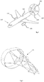
Figure 1 , is a schematic representation of an aircraft; -
Figure 2 , is a schematic representation of the support of the APU, according to the prior art; -
Figure 3 , is a schematic representation of a fish pole system in order to raise the APU inside the APU compartment, according to the prior art; -
Figure 4 , is a schematic representation of the elevator system in order to raise APU inside the APU compartment, according to an embodiment of the invention; -
Figure 5 , is a schematic representation of the APU inside the APU compartment; -
Figure 6a-6g , are schematic representations of different elements of the elevator system, according to an embodiment of the invention; - The present invention is directed generally toward elevator systems for auxiliary power unit ("APU"), and associated systems. A person skilled in the relevant art will understand, however, that the invention may have additional embodiments, and that the invention may be practiced without several of the details of the embodiments described below with reference to
figures 4-6f . - In an embodiment shown in
figure 4 , in order to proceed to the installation of theAPU 122 in its housing inside theAPU compartment 126, the invention propose the using of anelevator system 400 in order to replace thefish pole system 140 of the state of art. Theelevator system 400 comprises asupport 410 on which theAPU 122 is put down on its upper surface 411. Thesupport 410 is mounted on a set of wheels 413 or equivalent means, in order to move easily theAPU 122. The set of wheels 413 is able to move via a manual traction of thesupport 410 or via a set of electric motor with control unit able to be managed by a terminal. This terminal is able to be fixed and/or mobile from thesupport 410. The working of this terminal, its different modes of use and interaction with theelevator system 400 will be explain more in details during the rest of the description. - The upper surface 411 of the
support 410 comprise some attachments point in order to fasten at least twobase elements 420 rigidly on thesupport 410. Eachbase element 420, as shown in detail infigure 6a , comprises an electric motor comprising astator 421 fixed to thesupport 410 and a rotor fixed on acircular plate 422. Eachcircular plate 422 comprises firmly on itsupper surface 423 two parallel connectingrods 424. The connectingrods 424 comprise respectively ahole 425, such as both of thehole 425 are able to receive a throughbolt 426. The throughbolt 426 is able to be closed at the end with anut 427. Theelevator system 400 comprises also abar 450 comprising alower bar 460, astandard bar 470 and anupper bar 480. In order to explain the assembly phase of thebar 450 and its working in order to up or down the APU, we will start with the description from the upper bar to the lower bar. - As shown in
figure 6b , the upper bar comprises respectively two ends 481, 482, where theend 481 comprises ahole 483 fit to be able to receive an attachment means 484, as shown infigure 6c . This attachment means 484 comprises a fixation means 485, such as a fitting bolt, in order to fixate theelevator system 400 via theupper bar 480 to the structure of theAPU compartment 126. The attachment means 484 comprises also an expandable means 486, such as a spring system for example. The expandable means 486 is fitted in order to adjust the length of thebar 450 and fits the distance between theupper bar 480 and the upper surface 411 of thesupport 410. The expandable means 486 is able to fit to thehole 483 of theend 481 of theupper bar 480, such as to allow to thebar 450 to turn freely and avoid to the aircraft structure, and particularly the tail cone part to support the weight of the APU or any load. In order to reach this objective, the expandable means 486 is able to support load superior to 1000kg. Theend 482 of theupper bar 480 comprises ahole 487 able to receive afitting bolt 473 from astandard bar 470. - As shown in
figure 6d , eachstandard bar 470 comprises respectively two ends 471, 472, where afirst end 471 comprises afitting bolt 473 able to screw respectively inside thefitting hole upper bar 480 or of astandard bar 470, and where theend 472 comprises afitting hole 474 able to receive afitting bolt 473 fromstandard bar 470 or afitting bolt 463 fromlower bar 460. - Each
lower bar 460 comprises respectively two ends 461, 462. Afirst end 461 comprises afitting bolt 463 able to screw inside afitting hole 474 of thestandard bar 470 or thefitting hole 487 of theupper bar 480, and where thesecond end 462 comprises a throughbore 464 able to receive the throughbolt 426. - Each
upper bar 480,standard bar 470 orlower bar 460 is defined as being a metallic cylinder with a radius R and a height H, such as the radius R is defined sufficiently to support the weight W of the APU according the final height of thebar 450. - The
lower bar 460 comprise at its end 462 a flatcircular base 465 able to fit between the connectingrods 424. For that, the distance between the connectingrods 420 is 2R. The flatcircular base 465 allows to avoid the articulation of thebar 450 on the axis X, and thebolt 426 going through respectively thehole figure 6e , for connecting thebar 450 on theupper surface 423 of thecircular plate 422. - As shown in
figure 6f , the invention comprise also amount bracket 490 comprising two linked parts, where the first part is a translation means 491 on thebar 450, and the second part is a support means 492. The support means 492 is a bracket able to be fastened to thelateral part 122a, 122b of theAPU 122 viabolts 493. In a preferred embodiment, the translation means 491 comprises aring 494 comprising a female thread. Thelower bar 460 and thestandard bar 470 comprise respectively on their external surface amale thread 466, 476 such as the translation mean 492 is able to up until the higherstandard bar 470 or down until thelower bar 460 according the sense of rotation of thebar 450. In order to be able to raise any load such as the APU122, at least twobars 450 have to be positioned in order to bear the load of the APU. - The
Elevator System 400 according the invention is controlled and monitored by a terminal, able to be fixed and/or mobile from the support 410.The said terminal comprising a set of microprocessors and electronic associated, such as for example in a non-exhaustive list wireless emitters and receivers, a stylus, a voice recorder able via a tactile display to be an interface IHM between an operator and theelevator system 400. The said terminal via the set of microprocessors is the digital electronic controller that performs the logic for all working modes of theelevator system 400 such as: - the wireless synchronization phase of the different motors with the terminal;
- the control of the motor of the wheel 413;
- the control and regulation of the velocity to up or down the APU, and
- the different sequences of shut down;
- The terminal is able to manage the wireless synchronization phase of the different motors of the
elevator system 400 with the terminal. In order to do that, each motors comprise a control unit with wireless components associated, such as a wireless emitter and receiver. Each control unit is able to be in idle when the terminal is switch off or is out of the wireless field of the motors. The set of motors of theelevator system 400 are fed by a rechargeable and removable battery. The battery is housed on thesupport 410 in an accessible part but not on the surface 411. To perform the synchronization phase, the terminal apply the following steps: - determining of the list of wireless motors active, which contain three categories, such as "motor for direction" of the wheel 413, "motor for orientation" of the wheel 413, "motor to up and down" the load,
- connecting of the terminal to the wireless motor active,
- synchronization of step of each motor of each categories of motor in order to move step by step in the same direction, and/or orientation and/or velocity.
- The terminal is able via wireless communication to control the different motors of the wheel 413 in order to interact on the direction, orientation, velocity, and brake system. For that, the terminal apply the following steps:
- Detection of a set of instruction from the operator composed with a direction, such as move forward, or move backward, and an orientation, such as turn right, or turn left, or move threat;
- Deactivation of the brake system, put by default when the operator doesn't interact with the terminal;
- Regulation of the velocity to move the
support 410 according the pressure on the tactile interface of the terminal; - Activation of the brake system after complete realization of the instruction;
- The terminal is able to control and regulate the velocity to up and down the load, such as the
APU 122. For that, the terminal apply the following steps: - Detection of an instruction from the operator such as "UP" or "Down";
- Deactivation of the brake system, put by default when the operator doesn't interact with the terminal;
- Regulation of the velocity and the sense of rotation of each
bar 450 to move up or down the load via the translation of eachmount bracket 490, the said velocity being relative to the pressure on the tactile interface of the terminal; - Activation of the brake system after complete realization of the instruction;
- The terminal is able to proceed to different sequences of shut down. For that, the terminal apply the following steps:
- If detection of contradictory instructions, when activation of the brake system and the last instruction received is remove;
- for the motors of the wheels, if there is a detection of steps de-synchronization of at least one motor with respect to the others motors of its category, then activation of the brake system and setup of the counter of step;
- for the motors to up or down the load, if there is a detection of steps de-synchronization of at least one motor with respect to the others motors of its category, then activation of the brake system, except for the motors in advance until all mount bracket arrive at the same level that the others; for that the operator has the possibility to turn the motors not brake in order to down the load via the interface;
- if detection of a wireless de-synchronization of at least one motor with the terminal, then activation of the brake system and the synchronization phase restart;
- for any emergency or request from the operator to stop the Elevator System, the operator via the interface is able to activate the brake system.
- From the foregoing, it will be appreciated that specific embodiments of the invention have been described herein for purposes of illustration, but that various modifications may be made without deviating from the spirit and scope of the invention. For example, aspects of the invention described in the context of particular embodiments may be combined or eliminated in other embodiments. Although advantages associated with certain embodiments of the invention have been described in the context of those embodiments, other embodiments may also exhibit such advantages. Additionally, none of the foregoing embodiments need necessarily exhibit such advantages to fall within the scope of the invention. Accordingly, the invention is not limited except as by the appended claims.
Claims (9)
- Elevator system (400) in order to proceed to the installation of a heavy load (122) in its housing inside an aircraft (110) compartment (126) via a narrow door (125) located on the underneath of the said aircraft (110), comprising:- a support (410) mounted on a set of wheels (413), able to move via a manuel traction, or a set of electric motors, the said electric motors being able to be managed by a terminal;- the said support (410) comprising on its upper surface (411):- some attachment points in order to fasten at least two base elements (420), each base elements (420) being able to pivot a bar (450), the said bar (450) comprising:- an upper bar (480) comprising two ends (481, 482), where a first end (481) comprise a hole (483) fits to be able to receive an attachment mean (484) in order to fixate the elevator system (400), to the internal structure of the aircraft compartment (126), and where a second end (482) comprises a hole (487) able to receive a fitting bolt (473, 463),- at least one standard bar (470), comprising two ends (471, 472), where a first end (471) comprises a fitting bolt (473) respectively able to screw inside the fitting hole (487) of the upper bar (480), or the fitting hole (474) of a standard bar (470), and where the second end (472) comprises a fitting hole (474) able to receive a fitting bolt (473, 463);- a lower bar (460) comprising two ends (461, 462), where a first end (461) comprises a fitting bolt (463) able to screw respectively inside the fitting hole (474, 487), and where a second ends (462) comprise a through bore (464) able to receive a through bolt (426) allowing to link a bar (450) to a base element (420),- the said lower (460) and standard (470) bar comprising respectively on their external surface a male thread (466, 476), configure to allow the translation of a mount bracket (490) fastened to the lateral part (122a,122b) of the load, in order to up until the higher standard bar (470), or down until the lower bar (460) the said load according the sense of rotation of the bar 450;
- Elevator system (400) according claim 1 wherein, the terminal is able to be fixed and/or mobile from the support (410).
- Elevator system (400) according claim 1 or 2 wherein, the attachment means (484) comprise:- a fixation means (485), in order to fixate the elevator system (400) via the upper bar (480) to the internal structure of the aircraft compartment (126), and- an expandable means (486) fitted in order to adjust the length of the bar (450) and fits the distance between the upper bar (480) and the upper surface (411) of the support (410).
- Elevator system (400) according to claim 3 wherein, the expandable means (486) is able to fit to the hole (483) of the end (481) of the upper bar (480), such as to allow to the bar (450) to turn freely and avoid to the aircraft structure to support the weight of the load (122).
- Elevator System (400) according to claim 3 or 4 wherein, the expandable means (486) is able to support a weight of the load superior to 1000 kg.
- Process to manage an elevator system (400) according the previous claims, wherein in order to manage the wireless synchronization phase of the different motors of the elevator system (400), the terminal apply the following steps:- determining of the list of wireless motors active, which contain three categories, such as "motor for direction" of the wheel (413), "motor for orientation" of the wheel(413), "motor to up and down" the load (122),- connecting of the terminal to the wireless motor active,- synchronization of step of each motor of each categories of motor in order to move step by step in the same direction, and/or orientation and/or velocity.
- Process to manage an elevator system (400) according the previous claims, wherein to manage the wireless communication to control the different motors of the wheel (413) in order to interact on the direction, orientation, velocity, and brake system, the terminal apply the following steps:- Detection of a set of instruction from the operator composed with a direction, such as move forward, or move backward, and an orientation, such as turn right, or turn left, or move threat;- Deactivation of the brake system, put by default when the operator doesn't interact with the terminal;- Regulation of the velocity to move the support (410) according the pressure on the tactile interface of the terminal;- Activation of the brake system after complete realization of the instruction;
- Process to manage an elevator system (400) according the previous claims, wherein to control and regulate the velocity to up and down the load (122), the terminal apply the following steps:- Detection of an instruction from the operator such as "UP" or "Down";- Deactivation of the brake system, put by default when the operator doesn't interact with the terminal;- Regulation of the velocity and the sense of rotation of each bar (450) to move up or down the load via the translation of each mount bracket (490), the said velocity being relative to the pressure on the tactile interface of the terminal;- Activation of the brake system after complete realization of the instruction;
- Process to manage an elevator system (400) according the previous claims, wherein in order to proceed to different sequences of shut down, the terminal apply the following steps:- If detection of contradictory instructions, when activation of the brake system and the last instruction received is remove;- for the motors of the wheels, if there is a detection of steps de-synchronization of at least one motor with respect to the others motors of its category, then activation of the brake system and setup of the counter of step;- for the motors to up or down the load, if there is a detection of steps de-synchronization of at least one motor with respect to the others motors of its category, then activation of the brake system, except for the motors in advance until all mount bracket arrive at the same level that the others; for that the operator has the possibility to turn the motors not brake in order to down the load via the interface;- if detection of a wireless de-synchronization of at least one motor with the terminal, then activation of the brake system and the synchronization phase restart;- for any emergency or request from the operator to stop the elevator system (400), the operator via the interface is able to activate the brake system.
Priority Applications (3)
| Application Number | Priority Date | Filing Date | Title |
|---|---|---|---|
| EP16199282.1A EP3323731B1 (en) | 2016-11-17 | 2016-11-17 | Elevator system for auxiliary power unit |
| ES16199282T ES2813751T3 (en) | 2016-11-17 | 2016-11-17 | Lifting system for auxiliary power unit |
| US15/816,203 US10723606B2 (en) | 2016-11-17 | 2017-11-17 | Elevator system for auxiliary power unit |
Applications Claiming Priority (1)
| Application Number | Priority Date | Filing Date | Title |
|---|---|---|---|
| EP16199282.1A EP3323731B1 (en) | 2016-11-17 | 2016-11-17 | Elevator system for auxiliary power unit |
Publications (2)
| Publication Number | Publication Date |
|---|---|
| EP3323731A1 true EP3323731A1 (en) | 2018-05-23 |
| EP3323731B1 EP3323731B1 (en) | 2020-04-22 |
Family
ID=57345797
Family Applications (1)
| Application Number | Title | Priority Date | Filing Date |
|---|---|---|---|
| EP16199282.1A Active EP3323731B1 (en) | 2016-11-17 | 2016-11-17 | Elevator system for auxiliary power unit |
Country Status (3)
| Country | Link |
|---|---|
| US (1) | US10723606B2 (en) |
| EP (1) | EP3323731B1 (en) |
| ES (1) | ES2813751T3 (en) |
Families Citing this family (4)
| Publication number | Priority date | Publication date | Assignee | Title |
|---|---|---|---|---|
| EP3323731B1 (en) * | 2016-11-17 | 2020-04-22 | Airbus Operations S.L. | Elevator system for auxiliary power unit |
| US11661193B2 (en) * | 2019-07-18 | 2023-05-30 | Elroy Air, Inc. | Unmanned aerial vehicle optimization |
| WO2025153795A1 (en) * | 2024-01-16 | 2025-07-24 | Bae Systems Plc | Payload loading apparatus |
| EP4588719A1 (en) * | 2024-01-16 | 2025-07-23 | BAE SYSTEMS plc | Payload loading apparatus |
Citations (8)
| Publication number | Priority date | Publication date | Assignee | Title |
|---|---|---|---|---|
| US1993245A (en) * | 1931-08-04 | 1935-03-05 | Meron Frederic | Transporting and hoisting undercarriage |
| US2772004A (en) * | 1952-05-29 | 1956-11-27 | Jack D Noble | Portable gantry crane |
| US3120316A (en) * | 1958-09-25 | 1964-02-04 | Trianco Ltd | Loading aids |
| US3187907A (en) * | 1962-04-11 | 1965-06-08 | Northrop Corp | Transporting and elevating trailer |
| GB1086290A (en) * | 1965-01-11 | 1967-10-04 | Aeronautical Machinery Corp | Lifting device |
| US6039287A (en) * | 1996-08-02 | 2000-03-21 | Alliedsignal Inc. | Detachable integral aircraft tailcone and power assembly |
| DE202004015422U1 (en) * | 2003-10-02 | 2004-12-23 | Ic Industrial Consulting Gmbh | Positioning system for an overhead working vehicle, e.g. for use in aircraft maintenance, comprises a lower carrying vehicle, lifting arrangement, base plate and coupling arrangements for raising and lowering a tool or platform |
| CN204279977U (en) * | 2014-09-26 | 2015-04-22 | 中国商用飞机有限责任公司 | Hoisting mechanism for auxiliary power device of civil aircraft |
Family Cites Families (22)
| Publication number | Priority date | Publication date | Assignee | Title |
|---|---|---|---|---|
| US2702678A (en) * | 1950-09-23 | 1955-02-22 | Lockheed Aircraft Corp | Cargo loader for aircraft |
| US2867334A (en) * | 1954-09-10 | 1959-01-06 | Gen Dynamics Corp | Handling apparatus |
| US3028130A (en) * | 1957-11-01 | 1962-04-03 | Douglas Aircraft Co Inc | Cargo handling means for airplanes |
| US3552587A (en) * | 1968-04-16 | 1971-01-05 | Mc Donnell Douglas Corp | Powered hoist-baggage container handling system |
| US3858688A (en) * | 1972-03-10 | 1975-01-07 | G W Galloway Company | Self-contained mobile extendable tower |
| GB1474919A (en) * | 1973-08-13 | 1977-05-25 | Evans & Sons Ltd C | Builders scaffolding |
| US3972427A (en) * | 1974-09-25 | 1976-08-03 | The Boeing Company | Appendant elevatable loader for vehicles |
| US4586684A (en) * | 1983-09-01 | 1986-05-06 | Western Gear Corporation | Aircraft loading apparatus |
| EP0207008A3 (en) * | 1985-06-26 | 1987-10-21 | Maria Del Pilar Baguena Molina | Protective awning for scaffolding and tubular structures |
| EP0296916A1 (en) * | 1987-06-11 | 1988-12-28 | Gérard Saby | Modular building element, particularly for ladders or seaffolding |
| US5549408A (en) * | 1995-02-17 | 1996-08-27 | Lo; Wei W. | Connector for built-up toy furniture |
| FR2741034B1 (en) * | 1995-11-13 | 1998-01-02 | Lohr Ind | STRUCTURAL EQUIPMENT FOR A ROAD VEHICLE PROVIDING AN ADDITIONAL MOBILE FLOOR |
| US6123495A (en) * | 1998-06-16 | 2000-09-26 | Robertson Aviation L.L.C | Transport for moving and loading an auxiliary fuel tank |
| CA2303619C (en) * | 2000-03-31 | 2009-12-08 | Martin Faucher | Support structures |
| US8109363B2 (en) * | 2003-04-28 | 2012-02-07 | Dubbert Patrick C | Modular retaining wall fall protection system |
| CA2440788C (en) * | 2003-09-12 | 2012-01-03 | Jean-Paul Fredette | Motorized scaffold with displaceable worker support platform |
| US20050173601A1 (en) * | 2003-10-28 | 2005-08-11 | Hestand Larry D. | System for displaying a motor vehicle, apparatus and related methods |
| US20090278021A1 (en) * | 2008-05-06 | 2009-11-12 | Eads Construcciones Aeronauticas, S.A. | Device for removing and installing aircraft components |
| WO2012047787A1 (en) * | 2010-10-05 | 2012-04-12 | Whiting Corporation | Lifting bracket assembly including jack screw connector |
| FR3022528B1 (en) * | 2014-06-23 | 2018-01-26 | Airbus Operations | AN AIRCRAFT ENGINE HANDLING SYSTEM |
| EP3323731B1 (en) * | 2016-11-17 | 2020-04-22 | Airbus Operations S.L. | Elevator system for auxiliary power unit |
| US10843905B2 (en) * | 2017-04-04 | 2020-11-24 | Summation Labs, LLC | Systems and methods for slung load stabilization |
-
2016
- 2016-11-17 EP EP16199282.1A patent/EP3323731B1/en active Active
- 2016-11-17 ES ES16199282T patent/ES2813751T3/en active Active
-
2017
- 2017-11-17 US US15/816,203 patent/US10723606B2/en active Active
Patent Citations (8)
| Publication number | Priority date | Publication date | Assignee | Title |
|---|---|---|---|---|
| US1993245A (en) * | 1931-08-04 | 1935-03-05 | Meron Frederic | Transporting and hoisting undercarriage |
| US2772004A (en) * | 1952-05-29 | 1956-11-27 | Jack D Noble | Portable gantry crane |
| US3120316A (en) * | 1958-09-25 | 1964-02-04 | Trianco Ltd | Loading aids |
| US3187907A (en) * | 1962-04-11 | 1965-06-08 | Northrop Corp | Transporting and elevating trailer |
| GB1086290A (en) * | 1965-01-11 | 1967-10-04 | Aeronautical Machinery Corp | Lifting device |
| US6039287A (en) * | 1996-08-02 | 2000-03-21 | Alliedsignal Inc. | Detachable integral aircraft tailcone and power assembly |
| DE202004015422U1 (en) * | 2003-10-02 | 2004-12-23 | Ic Industrial Consulting Gmbh | Positioning system for an overhead working vehicle, e.g. for use in aircraft maintenance, comprises a lower carrying vehicle, lifting arrangement, base plate and coupling arrangements for raising and lowering a tool or platform |
| CN204279977U (en) * | 2014-09-26 | 2015-04-22 | 中国商用飞机有限责任公司 | Hoisting mechanism for auxiliary power device of civil aircraft |
Also Published As
| Publication number | Publication date |
|---|---|
| EP3323731B1 (en) | 2020-04-22 |
| US10723606B2 (en) | 2020-07-28 |
| ES2813751T3 (en) | 2021-03-24 |
| US20180162706A1 (en) | 2018-06-14 |
Similar Documents
| Publication | Publication Date | Title |
|---|---|---|
| EP3323731A1 (en) | Elevator system for auxiliary power unit | |
| US9783317B2 (en) | Power converter, generator and architecture for high efficiency auxiliary power unit | |
| CN102336275B (en) | For the method for airplane emergency electrical management | |
| US10396565B2 (en) | System and method for power distribution | |
| US5354233A (en) | Emergency ventilation system for elevator cab | |
| KR102019527B1 (en) | Method and system for regulating power in the event of at least one aircraft engine failure | |
| US9964044B2 (en) | Auxiliary power unit starting system for an aircraft | |
| CN104203653A (en) | Method for operating a motor vehicle during and/or following a collision | |
| US11300001B2 (en) | Electrical system for aircraft | |
| US10005370B2 (en) | Charging apparatus for vehicle | |
| CA2971338A1 (en) | Electric system stabilizing system for aircraft | |
| CN101710732B (en) | Unmanned helicopter continuous voltage-stabilizing power supply system with engine air restarting function | |
| KR101877181B1 (en) | Elevator operation apparatus including an emergency escape apparatus that transformers used both as control panel and escape apparatus and Control method thereof | |
| US9114888B2 (en) | RAM air turbine smoke isolation | |
| EP1494331A2 (en) | Aircraft secondary electric load controlling system | |
| US20170174357A1 (en) | Aircraft With A Bleed Supply Hybrid Architecture | |
| US20200023474A1 (en) | Remote panels for power systems | |
| CN103283105B (en) | Method and apparatus for the power train of operation of hybrid vehicle | |
| US20230100819A1 (en) | Interlock system, method, storage medium, and vehicle | |
| JP6794657B2 (en) | Electric vehicle power system | |
| CN109388120A (en) | A kind of new energy hybrid vehicle temprature control method and its system and vehicle | |
| KR20160150474A (en) | Apparatus and method for charging battery in electric vehicle having function of power failure | |
| JP7348497B2 (en) | Airport support vehicle and its charging method | |
| EP4501682A1 (en) | Safety system for operating machines | |
| HK1218100B (en) | Method for reactivating a train and device for carrying out said method |
Legal Events
| Date | Code | Title | Description |
|---|---|---|---|
| PUAI | Public reference made under article 153(3) epc to a published international application that has entered the european phase |
Free format text: ORIGINAL CODE: 0009012 |
|
| STAA | Information on the status of an ep patent application or granted ep patent |
Free format text: STATUS: THE APPLICATION HAS BEEN PUBLISHED |
|
| AK | Designated contracting states |
Kind code of ref document: A1 Designated state(s): AL AT BE BG CH CY CZ DE DK EE ES FI FR GB GR HR HU IE IS IT LI LT LU LV MC MK MT NL NO PL PT RO RS SE SI SK SM TR |
|
| AX | Request for extension of the european patent |
Extension state: BA ME |
|
| STAA | Information on the status of an ep patent application or granted ep patent |
Free format text: STATUS: REQUEST FOR EXAMINATION WAS MADE |
|
| RIN1 | Information on inventor provided before grant (corrected) |
Inventor name: PALOMARES MORA, ANGEL |
|
| 17P | Request for examination filed |
Effective date: 20181123 |
|
| RBV | Designated contracting states (corrected) |
Designated state(s): AL AT BE BG CH CY CZ DE DK EE ES FI FR GB GR HR HU IE IS IT LI LT LU LV MC MK MT NL NO PL PT RO RS SE SI SK SM TR |
|
| STAA | Information on the status of an ep patent application or granted ep patent |
Free format text: STATUS: EXAMINATION IS IN PROGRESS |
|
| 17Q | First examination report despatched |
Effective date: 20190313 |
|
| GRAP | Despatch of communication of intention to grant a patent |
Free format text: ORIGINAL CODE: EPIDOSNIGR1 |
|
| STAA | Information on the status of an ep patent application or granted ep patent |
Free format text: STATUS: GRANT OF PATENT IS INTENDED |
|
| INTG | Intention to grant announced |
Effective date: 20200117 |
|
| GRAS | Grant fee paid |
Free format text: ORIGINAL CODE: EPIDOSNIGR3 |
|
| GRAA | (expected) grant |
Free format text: ORIGINAL CODE: 0009210 |
|
| STAA | Information on the status of an ep patent application or granted ep patent |
Free format text: STATUS: THE PATENT HAS BEEN GRANTED |
|
| AK | Designated contracting states |
Kind code of ref document: B1 Designated state(s): AL AT BE BG CH CY CZ DE DK EE ES FI FR GB GR HR HU IE IS IT LI LT LU LV MC MK MT NL NO PL PT RO RS SE SI SK SM TR |
|
| REG | Reference to a national code |
Ref country code: CH Ref legal event code: EP |
|
| REG | Reference to a national code |
Ref country code: IE Ref legal event code: FG4D |
|
| REG | Reference to a national code |
Ref country code: DE Ref legal event code: R096 Ref document number: 602016034417 Country of ref document: DE |
|
| REG | Reference to a national code |
Ref country code: AT Ref legal event code: REF Ref document number: 1259770 Country of ref document: AT Kind code of ref document: T Effective date: 20200515 |
|
| REG | Reference to a national code |
Ref country code: LT Ref legal event code: MG4D |
|
| REG | Reference to a national code |
Ref country code: NL Ref legal event code: MP Effective date: 20200422 |
|
| PG25 | Lapsed in a contracting state [announced via postgrant information from national office to epo] |
Ref country code: SE Free format text: LAPSE BECAUSE OF FAILURE TO SUBMIT A TRANSLATION OF THE DESCRIPTION OR TO PAY THE FEE WITHIN THE PRESCRIBED TIME-LIMIT Effective date: 20200422 Ref country code: IS Free format text: LAPSE BECAUSE OF FAILURE TO SUBMIT A TRANSLATION OF THE DESCRIPTION OR TO PAY THE FEE WITHIN THE PRESCRIBED TIME-LIMIT Effective date: 20200822 Ref country code: NO Free format text: LAPSE BECAUSE OF FAILURE TO SUBMIT A TRANSLATION OF THE DESCRIPTION OR TO PAY THE FEE WITHIN THE PRESCRIBED TIME-LIMIT Effective date: 20200722 Ref country code: GR Free format text: LAPSE BECAUSE OF FAILURE TO SUBMIT A TRANSLATION OF THE DESCRIPTION OR TO PAY THE FEE WITHIN THE PRESCRIBED TIME-LIMIT Effective date: 20200723 Ref country code: FI Free format text: LAPSE BECAUSE OF FAILURE TO SUBMIT A TRANSLATION OF THE DESCRIPTION OR TO PAY THE FEE WITHIN THE PRESCRIBED TIME-LIMIT Effective date: 20200422 Ref country code: LT Free format text: LAPSE BECAUSE OF FAILURE TO SUBMIT A TRANSLATION OF THE DESCRIPTION OR TO PAY THE FEE WITHIN THE PRESCRIBED TIME-LIMIT Effective date: 20200422 Ref country code: PT Free format text: LAPSE BECAUSE OF FAILURE TO SUBMIT A TRANSLATION OF THE DESCRIPTION OR TO PAY THE FEE WITHIN THE PRESCRIBED TIME-LIMIT Effective date: 20200824 Ref country code: NL Free format text: LAPSE BECAUSE OF FAILURE TO SUBMIT A TRANSLATION OF THE DESCRIPTION OR TO PAY THE FEE WITHIN THE PRESCRIBED TIME-LIMIT Effective date: 20200422 |
|
| REG | Reference to a national code |
Ref country code: AT Ref legal event code: MK05 Ref document number: 1259770 Country of ref document: AT Kind code of ref document: T Effective date: 20200422 |
|
| PG25 | Lapsed in a contracting state [announced via postgrant information from national office to epo] |
Ref country code: LV Free format text: LAPSE BECAUSE OF FAILURE TO SUBMIT A TRANSLATION OF THE DESCRIPTION OR TO PAY THE FEE WITHIN THE PRESCRIBED TIME-LIMIT Effective date: 20200422 Ref country code: BG Free format text: LAPSE BECAUSE OF FAILURE TO SUBMIT A TRANSLATION OF THE DESCRIPTION OR TO PAY THE FEE WITHIN THE PRESCRIBED TIME-LIMIT Effective date: 20200722 Ref country code: RS Free format text: LAPSE BECAUSE OF FAILURE TO SUBMIT A TRANSLATION OF THE DESCRIPTION OR TO PAY THE FEE WITHIN THE PRESCRIBED TIME-LIMIT Effective date: 20200422 Ref country code: HR Free format text: LAPSE BECAUSE OF FAILURE TO SUBMIT A TRANSLATION OF THE DESCRIPTION OR TO PAY THE FEE WITHIN THE PRESCRIBED TIME-LIMIT Effective date: 20200422 |
|
| PG25 | Lapsed in a contracting state [announced via postgrant information from national office to epo] |
Ref country code: AL Free format text: LAPSE BECAUSE OF FAILURE TO SUBMIT A TRANSLATION OF THE DESCRIPTION OR TO PAY THE FEE WITHIN THE PRESCRIBED TIME-LIMIT Effective date: 20200422 |
|
| REG | Reference to a national code |
Ref country code: DE Ref legal event code: R097 Ref document number: 602016034417 Country of ref document: DE |
|
| PG25 | Lapsed in a contracting state [announced via postgrant information from national office to epo] |
Ref country code: IT Free format text: LAPSE BECAUSE OF FAILURE TO SUBMIT A TRANSLATION OF THE DESCRIPTION OR TO PAY THE FEE WITHIN THE PRESCRIBED TIME-LIMIT Effective date: 20200422 Ref country code: SM Free format text: LAPSE BECAUSE OF FAILURE TO SUBMIT A TRANSLATION OF THE DESCRIPTION OR TO PAY THE FEE WITHIN THE PRESCRIBED TIME-LIMIT Effective date: 20200422 Ref country code: EE Free format text: LAPSE BECAUSE OF FAILURE TO SUBMIT A TRANSLATION OF THE DESCRIPTION OR TO PAY THE FEE WITHIN THE PRESCRIBED TIME-LIMIT Effective date: 20200422 Ref country code: DK Free format text: LAPSE BECAUSE OF FAILURE TO SUBMIT A TRANSLATION OF THE DESCRIPTION OR TO PAY THE FEE WITHIN THE PRESCRIBED TIME-LIMIT Effective date: 20200422 Ref country code: AT Free format text: LAPSE BECAUSE OF FAILURE TO SUBMIT A TRANSLATION OF THE DESCRIPTION OR TO PAY THE FEE WITHIN THE PRESCRIBED TIME-LIMIT Effective date: 20200422 Ref country code: CZ Free format text: LAPSE BECAUSE OF FAILURE TO SUBMIT A TRANSLATION OF THE DESCRIPTION OR TO PAY THE FEE WITHIN THE PRESCRIBED TIME-LIMIT Effective date: 20200422 Ref country code: RO Free format text: LAPSE BECAUSE OF FAILURE TO SUBMIT A TRANSLATION OF THE DESCRIPTION OR TO PAY THE FEE WITHIN THE PRESCRIBED TIME-LIMIT Effective date: 20200422 |
|
| PG25 | Lapsed in a contracting state [announced via postgrant information from national office to epo] |
Ref country code: SK Free format text: LAPSE BECAUSE OF FAILURE TO SUBMIT A TRANSLATION OF THE DESCRIPTION OR TO PAY THE FEE WITHIN THE PRESCRIBED TIME-LIMIT Effective date: 20200422 Ref country code: PL Free format text: LAPSE BECAUSE OF FAILURE TO SUBMIT A TRANSLATION OF THE DESCRIPTION OR TO PAY THE FEE WITHIN THE PRESCRIBED TIME-LIMIT Effective date: 20200422 |
|
| PLBE | No opposition filed within time limit |
Free format text: ORIGINAL CODE: 0009261 |
|
| STAA | Information on the status of an ep patent application or granted ep patent |
Free format text: STATUS: NO OPPOSITION FILED WITHIN TIME LIMIT |
|
| REG | Reference to a national code |
Ref country code: ES Ref legal event code: FG2A Ref document number: 2813751 Country of ref document: ES Kind code of ref document: T3 Effective date: 20210324 |
|
| 26N | No opposition filed |
Effective date: 20210125 |
|
| PG25 | Lapsed in a contracting state [announced via postgrant information from national office to epo] |
Ref country code: SI Free format text: LAPSE BECAUSE OF FAILURE TO SUBMIT A TRANSLATION OF THE DESCRIPTION OR TO PAY THE FEE WITHIN THE PRESCRIBED TIME-LIMIT Effective date: 20200422 |
|
| PG25 | Lapsed in a contracting state [announced via postgrant information from national office to epo] |
Ref country code: MC Free format text: LAPSE BECAUSE OF FAILURE TO SUBMIT A TRANSLATION OF THE DESCRIPTION OR TO PAY THE FEE WITHIN THE PRESCRIBED TIME-LIMIT Effective date: 20200422 |
|
| REG | Reference to a national code |
Ref country code: CH Ref legal event code: PL |
|
| PG25 | Lapsed in a contracting state [announced via postgrant information from national office to epo] |
Ref country code: LU Free format text: LAPSE BECAUSE OF NON-PAYMENT OF DUE FEES Effective date: 20201117 |
|
| REG | Reference to a national code |
Ref country code: BE Ref legal event code: MM Effective date: 20201130 |
|
| PG25 | Lapsed in a contracting state [announced via postgrant information from national office to epo] |
Ref country code: LI Free format text: LAPSE BECAUSE OF NON-PAYMENT OF DUE FEES Effective date: 20201130 Ref country code: CH Free format text: LAPSE BECAUSE OF NON-PAYMENT OF DUE FEES Effective date: 20201130 |
|
| PG25 | Lapsed in a contracting state [announced via postgrant information from national office to epo] |
Ref country code: IE Free format text: LAPSE BECAUSE OF NON-PAYMENT OF DUE FEES Effective date: 20201117 |
|
| PG25 | Lapsed in a contracting state [announced via postgrant information from national office to epo] |
Ref country code: TR Free format text: LAPSE BECAUSE OF FAILURE TO SUBMIT A TRANSLATION OF THE DESCRIPTION OR TO PAY THE FEE WITHIN THE PRESCRIBED TIME-LIMIT Effective date: 20200422 Ref country code: MT Free format text: LAPSE BECAUSE OF FAILURE TO SUBMIT A TRANSLATION OF THE DESCRIPTION OR TO PAY THE FEE WITHIN THE PRESCRIBED TIME-LIMIT Effective date: 20200422 Ref country code: CY Free format text: LAPSE BECAUSE OF FAILURE TO SUBMIT A TRANSLATION OF THE DESCRIPTION OR TO PAY THE FEE WITHIN THE PRESCRIBED TIME-LIMIT Effective date: 20200422 |
|
| PG25 | Lapsed in a contracting state [announced via postgrant information from national office to epo] |
Ref country code: MK Free format text: LAPSE BECAUSE OF FAILURE TO SUBMIT A TRANSLATION OF THE DESCRIPTION OR TO PAY THE FEE WITHIN THE PRESCRIBED TIME-LIMIT Effective date: 20200422 |
|
| PG25 | Lapsed in a contracting state [announced via postgrant information from national office to epo] |
Ref country code: BE Free format text: LAPSE BECAUSE OF NON-PAYMENT OF DUE FEES Effective date: 20201130 |
|
| PGFP | Annual fee paid to national office [announced via postgrant information from national office to epo] |
Ref country code: DE Payment date: 20251119 Year of fee payment: 10 |
|
| PGFP | Annual fee paid to national office [announced via postgrant information from national office to epo] |
Ref country code: GB Payment date: 20251121 Year of fee payment: 10 |
|
| PGFP | Annual fee paid to national office [announced via postgrant information from national office to epo] |
Ref country code: FR Payment date: 20251126 Year of fee payment: 10 |
|
| PGFP | Annual fee paid to national office [announced via postgrant information from national office to epo] |
Ref country code: ES Payment date: 20251229 Year of fee payment: 10 |