EP3323646A2 - Axle system - Google Patents
Axle system Download PDFInfo
- Publication number
- EP3323646A2 EP3323646A2 EP17195855.6A EP17195855A EP3323646A2 EP 3323646 A2 EP3323646 A2 EP 3323646A2 EP 17195855 A EP17195855 A EP 17195855A EP 3323646 A2 EP3323646 A2 EP 3323646A2
- Authority
- EP
- European Patent Office
- Prior art keywords
- force
- clamping part
- axle
- tube
- engagement
- Prior art date
- Legal status (The legal status is an assumption and is not a legal conclusion. Google has not performed a legal analysis and makes no representation as to the accuracy of the status listed.)
- Granted
Links
- 238000004519 manufacturing process Methods 0.000 claims description 12
- 230000015572 biosynthetic process Effects 0.000 claims description 10
- 230000005489 elastic deformation Effects 0.000 claims description 5
- 238000012546 transfer Methods 0.000 abstract description 2
- 238000003780 insertion Methods 0.000 description 10
- 230000037431 insertion Effects 0.000 description 10
- 239000000463 material Substances 0.000 description 10
- 238000005755 formation reaction Methods 0.000 description 9
- 238000006073 displacement reaction Methods 0.000 description 7
- 238000013461 design Methods 0.000 description 6
- 239000002131 composite material Substances 0.000 description 5
- 238000000034 method Methods 0.000 description 4
- 229910000639 Spring steel Inorganic materials 0.000 description 3
- 230000000694 effects Effects 0.000 description 3
- 230000005540 biological transmission Effects 0.000 description 2
- 238000000465 moulding Methods 0.000 description 2
- 239000000725 suspension Substances 0.000 description 2
- 229910000640 Fe alloy Inorganic materials 0.000 description 1
- 229910000831 Steel Inorganic materials 0.000 description 1
- 230000006978 adaptation Effects 0.000 description 1
- 238000005452 bending Methods 0.000 description 1
- 230000002787 reinforcement Effects 0.000 description 1
- 238000007788 roughening Methods 0.000 description 1
- 239000010959 steel Substances 0.000 description 1
- 238000012549 training Methods 0.000 description 1
Images


Classifications
-
- B—PERFORMING OPERATIONS; TRANSPORTING
- B60—VEHICLES IN GENERAL
- B60G—VEHICLE SUSPENSION ARRANGEMENTS
- B60G11/00—Resilient suspensions characterised by arrangement, location or kind of springs
- B60G11/02—Resilient suspensions characterised by arrangement, location or kind of springs having leaf springs only
- B60G11/10—Resilient suspensions characterised by arrangement, location or kind of springs having leaf springs only characterised by means specially adapted for attaching the spring to axle or sprung part of the vehicle
- B60G11/113—Mountings on the axle
-
- B—PERFORMING OPERATIONS; TRANSPORTING
- B60—VEHICLES IN GENERAL
- B60B—VEHICLE WHEELS; CASTORS; AXLES FOR WHEELS OR CASTORS; INCREASING WHEEL ADHESION
- B60B35/00—Axle units; Parts thereof ; Arrangements for lubrication of axles
- B60B35/12—Torque-transmitting axles
- B60B35/16—Axle housings
- B60B35/166—Axle housings characterised by reinforcements, e.g. reinforcement ribs
-
- B—PERFORMING OPERATIONS; TRANSPORTING
- B60—VEHICLES IN GENERAL
- B60G—VEHICLE SUSPENSION ARRANGEMENTS
- B60G7/00—Pivoted suspension arms; Accessories thereof
- B60G7/008—Attaching arms to unsprung part of vehicle
-
- B—PERFORMING OPERATIONS; TRANSPORTING
- B60—VEHICLES IN GENERAL
- B60G—VEHICLE SUSPENSION ARRANGEMENTS
- B60G9/00—Resilient suspensions of a rigid axle or axle housing for two or more wheels
- B60G9/003—Resilient suspensions of a rigid axle or axle housing for two or more wheels the axle being rigidly connected to a trailing guiding device
-
- B—PERFORMING OPERATIONS; TRANSPORTING
- B60—VEHICLES IN GENERAL
- B60G—VEHICLE SUSPENSION ARRANGEMENTS
- B60G2204/00—Indexing codes related to suspensions per se or to auxiliary parts
- B60G2204/10—Mounting of suspension elements
- B60G2204/12—Mounting of springs or dampers
- B60G2204/121—Mounting of leaf springs
-
- B—PERFORMING OPERATIONS; TRANSPORTING
- B60—VEHICLES IN GENERAL
- B60G—VEHICLE SUSPENSION ARRANGEMENTS
- B60G2204/00—Indexing codes related to suspensions per se or to auxiliary parts
- B60G2204/10—Mounting of suspension elements
- B60G2204/14—Mounting of suspension arms
- B60G2204/148—Mounting of suspension arms on the unsprung part of the vehicle, e.g. wheel knuckle or rigid axle
-
- B—PERFORMING OPERATIONS; TRANSPORTING
- B60—VEHICLES IN GENERAL
- B60G—VEHICLE SUSPENSION ARRANGEMENTS
- B60G2204/00—Indexing codes related to suspensions per se or to auxiliary parts
- B60G2204/40—Auxiliary suspension parts; Adjustment of suspensions
- B60G2204/43—Fittings, brackets or knuckles
- B60G2204/4306—Bracket or knuckle for rigid axles, e.g. for clamping
-
- B—PERFORMING OPERATIONS; TRANSPORTING
- B60—VEHICLES IN GENERAL
- B60G—VEHICLE SUSPENSION ARRANGEMENTS
- B60G2204/00—Indexing codes related to suspensions per se or to auxiliary parts
- B60G2204/61—Adjustable during maintenance
Landscapes
- Engineering & Computer Science (AREA)
- Mechanical Engineering (AREA)
- Clamps And Clips (AREA)
- Steering Devices For Bicycles And Motorcycles (AREA)
Abstract
Betrifft ein Achssystem, insbesondere zum Einsatz in Nutzfahrzeugen, umfassend ein Achsrohr (2) einen Lenker (6), wobei sich das Achsrohr (2) längs einer Rohrachse (R) erstreckt, wobei eine Verbindungseinheit (4) vorgesehen ist, welche ein Halteelement (42), ein erstes Klemmteil (5) und eine Krafteinheit (7) aufweist, wobei das Halteelement (42) stoffschlüssig am Achsrohr (2) festlegbar ist, wobei das erste Klemmteil (5) zumindest teilweise auf der dem Achsrohr (2) abgewandten Seite des Lenkers (6) anordenbar und mit dem Lenker in kraftschlüssigen Eingriff bringbar ist, wobei die Krafteinheit (7) ausgelegt ist, eine Klemmkraft vom Halteelement (42) auf das erste Klemmteil (5) mittelbar oder unmittelbar zu übertragen.Concerns an axle system, in particular for use in commercial vehicles, comprising an axle tube (2) a handlebar (6), wherein the axle tube (2) along a tube axis (R) extends, wherein a connecting unit (4) is provided, which is a holding element ( 42), a first clamping part (5) and a power unit (7), wherein the holding element (42) cohesively on the axle tube (2) can be fixed, wherein the first clamping part (5) at least partially on the side facing away from the axle tube (2) the handlebar (6) can be arranged and in frictional engagement with the handlebar, wherein the force unit (7) is adapted to transfer a clamping force from the holding element (42) on the first clamping part (5) directly or indirectly.
Description
Die vorliegende Erfindung betrifft ein Achssystem insbesondere zum Einsatz in Nutzfahrzeugen sowie ein Verfahren zur Herstellung eines solchen Achssystems.The present invention relates to an axle system, in particular for use in commercial vehicles, and to a method for producing such an axle system.
Achssysteme insbesondere zur Verbindung eines Längslenkers mit einem Achsrohr sind aus dem Stand der Technik bekannt. Weiterhin bekannt ist es dabei, dass zur Sicherung des Lenkers gegen Verlagerung relativ zum Achsrohr eine vorwiegend durch Kraftschluss erzeugte Verbindung eingesetzt wird. Hierbei hat es sich insbesondere bewährt, u-förmige Zugelemente einzusetzen, welche das Achsrohr umschlingen und gegenüber einer Klemmplatte, welche wiederum am Längslenker eingreift, verspannt werden. Einer der Nachteile dieser Verbindungsmöglichkeit zwischen Achsrohr und Längslenker ist, dass die Sicherheit gegen Verlagerung oder Verdrehung des Achsrohrs relativ zum Längslenker oftmals nicht ausreichend für die hohen Belastungen in Nutzfahrzeugen ist. Um diesem Nachteil beizukommen, wurden, weiterhin im Stand der Technik bekannt, einzelne Elemente der kraftschlüssigen Verbindung zwischen Achsrohr und Längslenker mit dem Längslenker oder dem Achsrohr verschweißt, so dass die kraftschlüssige Verbindung durch einen zusätzlichen Stoffschluss unterstützt wird. Nachteilig bei dieser Festlegungsmöglichkeit ist, dass die Position des Längslenkers relativ zur Längsachse des Achsrohrs nicht weiter eingestellt werden kann. Es ist daher unmöglich, nach der Herstellung des Stoffschlusses zwischen einem der Befestigungselemente und dem jeweiligen Bauteil am Fahrwerksystem die Montageposition von Achsrohr und Längslenker zu justieren und gegebenenfalls an geänderte Fahrwerkskomponenten anzupassen.Axle systems, in particular for connecting a trailing arm to an axle tube, are known from the prior art. It is also known that to secure the handlebar against displacement relative to the axle tube, a connection mainly generated by adhesion is used. In this case, it has proven particularly useful to use U-shaped tension elements which wrap around the axle tube and against a clamping plate, which in turn engages the trailing arm, are braced. One of the disadvantages of this connection between axle tube and trailing arm is that the safety against displacement or rotation of the axle tube relative to the trailing arm is often not sufficient for the high loads in commercial vehicles. In order to overcome this disadvantage, individual elements of the frictional connection between axle tube and trailing arm were welded to the trailing arm or the axle tube, so that the non-positive connection is supported by an additional material connection. A disadvantage of this Festlegungsmöglichkeit is that the position of the trailing arm relative to the longitudinal axis of the axle tube can not be adjusted. It is therefore impossible to adjust the mounting position of the axle tube and trailing arm after manufacture of the material connection between one of the fasteners and the respective component on the chassis system and optionally adapted to modified suspension components.
Aufgabe der vorliegenden Erfindung ist die Bereitstellung eines Achssystems, welches die im Stand der Technik auftretenden Nachteile beseitigt und insbesondere eine vereinfachte Positionierung des Lenkers relativ zum Achsrohr ermöglicht.Object of the present invention is to provide an axle system, which eliminates the disadvantages occurring in the prior art and in particular allows a simplified positioning of the link relative to the axle tube.
Diese Aufgaben werden gelöst mit einem Achssystem gemäß Anspruch 1 sowie einem Verfahren zur Herstellung eines Achssystems gemäß Anspruch 15.These objects are achieved with an axle system according to claim 1 and a method for producing an axle system according to claim 15.
Erfindungsgemäß umfasst das Achssystem ein Achsrohr und einen Lenker, wobei sich das Achsrohr längs einer Rohrachse erstreckt, wobei eine Verbindungseinheit vorgesehen ist, welche ein Halteelement, ein erstes Klemmteil und eine Krafteinheit aufweist, wobei das Halteelement stoffschlüssig am Achsrohr festlegbar ist, wobei das erste Klemmteil zumindest teilweise auf der dem Achsrohr abgewandten Seite des Lenkers anordenbar und mit dem Lenker in kraftschlüssigen Eingriff bringbar ist, wobei die Krafteinheit ausgelegt ist, eine Klemmkraft vom Halteelement auf das erste Klemmteil mittelbar oder unmittelbar zu übertragen. Das Achssystem, welches insbesondere zum Einsatz in Nutzfahrzeugen, wie beispielsweise einer Zugmaschine eines LKW-Gespannes oder in einem Anhänger, Anwendung findet, umfasst die Hauptkomponenten Achsrohr, Lenker und Verbindungseinheit. Das Achsrohr ist dabei vorzugsweise eine starre Achse, welche sich im Wesentlichen zylinderförmig oder rechteckig mit hohlem Querschnitt längs einer Rohrachse erstreckt. Dabei fällt unter den Begriff Achsrohr vorzugsweise auch ein an einem Achsrohr festgelegter Achsstummel, welcher im Wesentlichen koaxial zur Rohrachse angeordnet ist und der Lagerung eines Fahrzeugrads dient. Weiterhin ist der Lenker bevorzugt der Längslenker eines Nutzfahrzeugs, welcher an seinem ersten distalen Ende schwenkbar am Rahmen des Nutzfahrzeugs aufgehängt ist und im Bereich, in welchem er das Achsrohr kreuzt, am Achsrohr festgelegt werden kann. Der Lenker kann dabei unter anderem ein traditioneller Lenker wie beispielsweise ein Längslenker oder auch ein Federelement wie beispielsweise eine Blattfeder sein. Weiterhin weist der Lenker vorzugsweise einen Eingriffsbereich für ein Federelement, wie beispielsweise eine Spiralfeder oder eine Luftfeder, auf.According to the invention, the axle system comprises an axle tube and a handlebar, wherein the axle tube extends along a tube axis, wherein a connecting unit is provided, which has a holding element, a first clamping part and a power unit, wherein the holding element is cohesively fixed to the axle tube, wherein the first clamping part at least partially on the side facing away from the axle tube of the handlebar and can be brought into frictional engagement with the handlebar, wherein the power unit is designed to transfer a clamping force from the holding member to the first clamping member directly or indirectly. The axle system, which is used in particular for use in commercial vehicles, such as a tractor of a truck-trailer or in a trailer, application, comprises the main components axle tube, handlebar and connecting unit. The axle tube is preferably a rigid axle, which extends substantially cylindrical or rectangular with a hollow cross-section along a tube axis. In this case, the term axle tube preferably also includes a stub axle which is fixed to an axle tube and which is arranged essentially coaxially to the tube axis and serves to support a vehicle wheel. Furthermore, the handlebar is preferably the trailing arm of a commercial vehicle, which is suspended at its first distal end pivotally mounted on the frame of the utility vehicle and in the area in which it crosses the axle tube, can be fixed to the axle tube. The handlebar may be, inter alia, a traditional handlebar such as a trailing arm or a spring element such as a leaf spring. Furthermore, the handlebar preferably has an engagement region for a spring element, such as a coil spring or an air spring, on.
Dabei ist der Lenker vorzugsweise als Federstahllenker mit im Wesentlichen rechteckigem Querschnitt ausgebildet. Als Herstellungsmaterial kann aufgrund der Verwendung einer Verbindungseinheit im Sinne der vorliegenden Erfindung ein Material verwendet werden, welches nicht schweißbar ist. So kommt insbesondere Federstahl für die Herstellung des Lenkers in Betracht. Es versteht sich, dass unabhängig von der Festlegungsmethode des Lenkers auch schweißbare Eisenlegierungen zum Einsatz gelangen können. Die Verbindungseinheit besteht aus drei Hauptkomponenten. Zunächst ist ein Halteelement vorgesehen, welches stoffschlüssig am Achsrohr festlegbar oder festgelegt ist. Im montierten Zustand des Achssystems ist dabei das Halteelement vorzugsweise am Achsrohr angeschweißt. Weiterhin kommt ein erstes Klemmelement zum Einsatz, welches zumindest teilweise, vorzugsweise überwiegend auf der dem Achsrohr abgewandten Seite des Lenkers angeordnet ist und mit dem Lenker in kraftschlüssigen Eingriff bringbar oder gebracht ist. Die Anordnung des Klemmteils zumindest teilweise oder überwiegend auf der dem Achsrohr abgewandten Seite bedeutet, dass weitere Bereiche des ersten Klemmteils den Lenker auf seinen Seiten jeweils überragen und teilweise umschließen können und somit nicht nur auf der dem Achsrohr abgewandten Seite angeordnet sind. Bevorzugt ist das erste Klemmteil mit ca. 75% bis 95% seines Volumens auf der dem Achsrohr gegenüber liegenden Seite des Lenkers angeordnet, da hierdurch besonders hohe Anpresskräfte bei niedrigem Gesamtgewicht des Achssystems erreicht werden können. Mit Vorteil wird zur Herstellung des Kraftschlusses zwischen dem ersten Klemmteil und dem Lenker vorzugsweise der Hauptteil der vom ersten Klemmteil auf den Lenker übertragenen Kraft auf die, dem Achsrohr abgewandte Seite des Lenkers übertragen, wodurch der Lenker gegen das Achsrohr und/oder gegen das auf dem Achsrohr festgelegte Halteelement gepresst wird. Die Krafteinheit ist vorzugsweise ein Verbund von Bauteilen, welcher ausgelegt ist, die erforderliche Zugkraft oder Anpresskraft zwischen dem Halteelement und dem ersten Klemmteil zu erzeugen. Dabei ist die Krafteinheit vorzugsweise zweiteilig ausgebildet, wobei ein erstes Teil vorzugsweise form- und kraftschlüssig in ein zweites Teil eingreift und wodurch bei der Montage des Achssystems zwischen den beiden Teilen der Krafteinheit eine Verlagerung stattfindet und hierdurch eine elastische Verformung zumindest eines der Teile der Krafteinheit in einer zwischen den Teilen der Krafteinheit wirkenden Zugkraft bzw. Klemmkraft resultiert. Dass die Klemmkraft sowohl mittelbar als auch unmittelbar zwischen dem Halteelement und dem ersten Klemmteil wirken kann, bedeutet, dass zur Erhöhung der Funktionssicherheit insbesondere bei starken Schwingungen am Achssystem weitere, vorzugsweise elastische Bauteile zwischen der Krafteinheit und dem ersten Klemmteil zum Eingriff gebracht werden können. Der Vorteil des erfindungsgemäßen Achssystems ist, dass die Vorzüge einer stoffschlüssigen Verbindung mit den Vorzügen einer kraftschlüssigen Verbindung zwischen dem Achsrohr und dem Lenker kombiniert werden können, so dass einerseits eine hohe Funktionssicherheit herstellbar ist und andererseits eine Demontage des Achssystems und insbesondere eine versetzte Anordnung des Lenkers relativ zum Achsrohr möglich ist.In this case, the link is preferably designed as a spring steel link with a substantially rectangular cross-section. As a manufacturing material, due to the use of a connection unit in the sense of the present invention, a material which is not weldable can be used. Thus, in particular spring steel for the production of the handlebar into consideration. It is understood that regardless of the method of determining the handlebar and weldable iron alloys can be used. The connection unit consists of three main components. First, a holding element is provided, which is cohesively fixed or fixed to the axle tube. In the mounted state of the axle system, the retaining element is preferably welded to the axle tube. Furthermore, a first clamping element is used, which is arranged at least partially, preferably predominantly on the side facing away from the axle tube of the handlebar and can be brought or brought into frictional engagement with the handlebar. The arrangement of the clamping part at least partially or predominantly on the side facing away from the axle tube means that further areas of the first clamping part can project beyond the handlebars on its sides and partially enclose them and thus are arranged not only on the side facing away from the axle tube. The first clamping part is preferably arranged with approximately 75% to 95% of its volume on the side of the link opposite the axle tube, since in this way particularly high contact forces can be achieved with a low overall weight of the axle system. Advantageously, to produce the frictional connection between the first clamping part and the handlebar, preferably the main part of the force transferred from the first clamping part to the handlebar is transferred to the side facing away from the axle tube of the handlebar, whereby the handlebar against the axle tube and / or against on the Axle tube fixed holding element is pressed. The power unit is preferably a composite of components which is designed to generate the required tensile force or contact force between the retaining element and the first clamping part. In this case, the power unit is preferably formed in two parts, wherein a first part preferably positively and non-positively engages in a second part and whereby during the assembly of the axle system between the two parts of the power unit, a displacement takes place and thereby an elastic deformation of at least one the parts of the force unit in a force acting between the parts of the power unit tensile force or clamping force results. The fact that the clamping force can act both indirectly and directly between the retaining element and the first clamping part means that further, preferably elastic components between the force unit and the first clamping part can be brought into engagement to increase the reliability, especially in strong vibrations on the axle system. The advantage of the axle system according to the invention is that the advantages of a cohesive connection with the advantages of a non-positive connection between the axle tube and the handlebar can be combined, so that on the one hand high reliability can be produced and on the other hand disassembly of the axle system and in particular a staggered arrangement of the handlebar relative to the axle tube is possible.
Besonders bevorzugt wirkt die Klemmkraft parallel zu einer Kraftachse, welche orthogonal zur Rohrachse verläuft. Dies bedeutet insbesondere für den Fall, dass nur eine Krafteinheit vorgesehen ist, dass die Achse, entlang derer die von der Krafteinheit aufgebrachte Klemmkraft wirkt, die Rohrachse im Wesentlichen orthogonal schneidet. Es versteht sich, dass für den Fall, dass eine Vielzahl von Krafteinheiten vorgesehen ist, die jeweils resultierende aller aufgebrachten Kräfte orthogonal zur Rohrachse verläuft, wobei die einzelnen Klemmkräfte auch entlang von Achsen wirken können, welche windschief zur Rohrachse angeordnet sind. Der Vorteil bei der Etablierung einer aus zumindest zwei Einzelkräften resultierenden Klemmkraft, welche im Wesentlichen orthogonal zur Rohrachse verläuft, ist, dass keine Rotationsmomente im Verbindungsbereich zwischen dem Achsrohr und dem Lenker durch die Krafteinheit erzeugt werden, welche eine Schwächung des Achssystems bedeuten würden.Particularly preferably, the clamping force acts parallel to a force axis which is orthogonal to the tube axis. This means, in particular in the case where only one force unit is provided, that the axis along which the clamping force applied by the force unit acts intersects the tube axis substantially orthogonally. It is understood that in the event that a plurality of force units is provided, the respective resultant of all applied forces is orthogonal to the tube axis, wherein the individual clamping forces can also act along axes which are skewed to the tube axis. The advantage of establishing a clamping force resulting from at least two individual forces, which is substantially orthogonal to the tube axis, is that no rotational moments are generated in the connection region between the axle tube and the link by the force unit, which would weaken the axle system.
Mit Vorteil weist die Krafteinheit ein erstes Kraftelement und ein zweites Kraftelement auf, wobei das erste Kraftelement im Wesentlichen rotationssymmetrisch um die Kraftachse ausgebildet ist. Mit Vorteil besteht dabei die Krafteinheit aus einem ersten Kraftelement, welches als Gewindebolzen ausgebildet ist, und einem zweiten Kraftelement, welches mit einem korrespondierenden Innengewinde versehen ist, wie beispielsweise eine Mutter. Als im Wesentlichen rotationssymmetrische Ausbildung des ersten Kraftelements wird dabei im Rahmen der vorliegenden Erfindung auch ein Außengewinde angesehen, welches zwar per se nicht rotationssymmetrisch um die Kraftachse ist, sich aber bezogen auf seine Außen- oder Innenerstreckung jeweils rotationssymmetrisch um die Kraftachse erstreckt. Im Rahmen der vorliegenden Erfindung ist es dabei bevorzugt, dass das erste Kraftelement keine Krümmung aufweist, welche eine Abweichung von der Kraftachse aufweist. Insbesondere soll also kein U-Bügel wie beim aus dem Stand der Technik bekannten Achssystem zum Einsatz gelangen. Dies hat den Vorteil, dass sämtliche im ersten Kraftelement auftretenden Kräfte jeweils ohne Querkomponenten als reine Zugkräfte auftreten und auf diese Weise mit geringerem Materialeinsatz höhere Kräfte aufgebracht werden können.Advantageously, the force unit has a first force element and a second force element, wherein the first force element is formed substantially rotationally symmetrical about the force axis. Advantageously, the force unit consists of a first force element, which is designed as a threaded bolt, and a second force element, which is provided with a corresponding internal thread is like a mother. As an essentially rotationally symmetrical design of the first force element in the context of the present invention, an external thread is considered, which is not rotationally symmetrical per se about the force axis, but extends in relation to its outer or inner extension in each case rotationally symmetrical about the force axis. In the context of the present invention, it is preferred that the first force element has no curvature which has a deviation from the force axis. In particular, therefore, no U-bracket should be used as in the known from the prior art axle system. This has the advantage that all forces occurring in the first force element each occur without transverse components as pure tensile forces and in this way with less material use higher forces can be applied.
Weiterhin bevorzugt weist das Halteelement eine Eingriffsgeometrie auf, in und/oder mit welcher die Krafteinheit derart in Eingriff bringbar ist, dass zumindest in einer Richtung parallel zur Kraftachse ein Formschluss zwischen der Krafteinheit und dem Halteelement hergestellt ist. Die Eingriffsgeometrie des Halteelements ist vorzugsweise derart ausgebildet, dass zwischen der Krafteinheit und dem Halteelement eine längs der Kraftachse wirkende Hinterschneidung gebildet wird. Vorzugsweise ist dabei die Eingriffsgeometrie derart ausgelegt, dass nur in einer Richtung parallel zur Kraftachse dieser Formschluss eine Kraftübertragung zwischen der Krafteinheit und dem Halteelement ermöglicht. Bevorzugt kann auch der Kontaktbereich zwischen Krafteinheit, bzw. insbesondere deren erstem Kraftelement, und Halteelement, insbesondere im Bereich dessen Eingriffsgeometrie, eine reibungserhöhende Oberflächengestaltung vorgesehen sein, die insbesondere als Aufrauhung oder Profilierung ausgebildet ist. Die reibungserhöhende Oberflächengestaltung kann an einem der Elemente Krafteinheit und Halteelement oder beiden vorgesehen sein.Further preferably, the holding element has an engagement geometry, in and / or with which the force unit can be brought into engagement such that a positive connection between the force unit and the holding element is produced at least in one direction parallel to the force axis. The engagement geometry of the retaining element is preferably designed such that an undercut acting along the force axis is formed between the force unit and the retaining element. Preferably, the engagement geometry is designed such that only in one direction parallel to the force axis of this positive connection enables a power transmission between the power unit and the support member. The contact region between the force unit, or in particular its first force element, and holding element, in particular in the region of its engagement geometry, may also preferably be provided with a friction-increasing surface design, which is designed in particular as a roughening or profiling. The friction-increasing surface design may be provided on one of the elements of force unit and retaining element or both.
Mit Vorteil ist die Eingriffsgeometrie dabei ausgelegt, die Krafteinheit an einer von zumindest zwei, längs der Rohrachse voneinander beabstandeten Eingriffspositionen festzulegen. In einer ersten bevorzugten Ausführungsform ist dabei eine Eingriffsgeometrie derart ausgebildet, dass die Krafteinheit an zumindest zwei Positionen im formschlüssigen Eingriff mit dem Halteelement bringbar ist. Dies kann dadurch erreicht werden, dass die Eingriffsgeometrie als im Wesentlichen langlochförmige Aussparung mit einer entsprechenden Anschlagfläche, zwischen welcher ein Formschluss zwischen der Krafteinheit und der Eingriffsgeometrie herstellbar ist, ausgebildet ist.Advantageously, the engagement geometry is designed to fix the power unit at one of at least two, spaced along the tube axis engagement positions. In a first preferred embodiment is thereby an engagement geometry is formed such that the force unit can be brought in at least two positions in positive engagement with the retaining element. This can be achieved in that the engagement geometry is formed as a substantially slot-shaped recess with a corresponding stop surface, between which a positive connection between the force unit and the engagement geometry can be produced.
Alternativ hierzu können auch mehrere Eingriffsgeometrien am Halteelement ausgebildet sein, welche derart voneinander beabstandet sind, dass verschiedene Befestigungspositionen zwischen dem Halteelement und dem Lenker ausgewählt werden können. Vorzugsweise ist dabei die Anzahl der Eingriffsgeometrien größer als die Anzahl der eingesetzten Krafteinheiten, so dass eine Krafteinheit mit einer von mehreren Eingriffsgeometrien in Eingriff gebracht werden kann. Dabei ist der Abstand der Eingriffspositionen voneinander vorzugsweise kleiner als die Lenkerbreite. In einer besonders bevorzugten Ausführungsform sind dabei zumindest drei Befestigungspositionen an der Eingriffsgeometrie oder über eine Vielzahl von Eingriffsgeometrien einstellbar. Der Vorteil der Möglichkeit, die Krafteinheit an verschiedenen Eingriffspositionen am Halteelement festzulegen, liegt darin, dass zum einen verschiedene Lenkerbreiten im Achssystem ohne weiteres verwendet werden können und zum anderen an ein und demselben Verbund aus Halteelement und Achsrohr verschiedene Befestigungspositionen für einen Lenker durch einen Monteur jederzeit eingestellt werden können.Alternatively, a plurality of engagement geometries may be formed on the retaining element, which are spaced apart from one another such that different attachment positions between the retaining element and the handlebar can be selected. Preferably, the number of engagement geometries is greater than the number of force units used, so that a force unit can be brought into engagement with one of a plurality of engagement geometries. The distance of the engagement positions from each other is preferably smaller than the handlebar width. In a particularly preferred embodiment, at least three attachment positions on the engagement geometry or on a plurality of engagement geometries are adjustable. The advantage of the ability to set the power unit at different engagement positions on the holding element, is that for a different handlebar widths in the axis system can be used easily and on the other to one and the same composite of support member and axle different attachment positions for a handlebar by a fitter at any time can be adjusted.
Vorzugsweise sind zwei Krafteinheiten vorgesehen, welche parallel zur Rohrachse beabstandet, je eine Klemmkraft auf das erste Klemmteil übertragen. Durch den Einsatz von zwei Krafteinheiten, wobei an jeder Seite des Lenkers, d.h. parallel zur Rohrachse versetzt, je eine Krafteinheit zwischen dem Halteelement und dem ersten Klemmteil wirkt, kann erreicht werden, dass der Lenker stabiler mit dem Achsrohr in Verbindung bringbar ist. Darüber hinaus kann durch den Einsatz von zwei Krafteinheiten die Wahrscheinlichkeit für einen Totalausfall des Achssystems verringert werden, da auch bei Reduzierung der Klemmkraft an einer der Krafteinheiten ein vollständiges Ablösen des Lenkers vom Achsrohr relativ unwahrscheinlich ist, da stets eine zweite Krafteinheit zur Absicherung der kraftschlüssigen Verbindung zwischen Lenker und Rohrachse bereitsteht. Darüber hinaus kann durch den Einsatz von zwei Krafteinheiten auch ein Verschwenken des Lenkers um seine Längsachse relativ zum Achsrohr verhindert werden. Weiterhin ist durch den Einsatz von zwei Krafteinheiten keine Bohrung im Lenker erforderlich, wodurch die Kerbwirkungen im Material des Lenkers verringert werden können und insbesondere ein dünnerer Lenker eingesetzt werden kann, welcher ein geringeres Gewicht aufweist.Preferably, two force units are provided, which are spaced parallel to the tube axis, each transmitting a clamping force to the first clamping part. Through the use of two force units, each offset by a force unit between the holding member and the first clamping member on each side of the link, ie offset parallel to the tube axis, it can be achieved that the handlebar is more stable with the axle tube in connection can be brought. In addition, the use of two units of force can reduce the likelihood of total failure of the axle system, since even if the clamping force on one of the power units is reduced, complete detachment of the handlebar from the axle tube is relatively unlikely is because there is always a second power unit to secure the positive connection between the handlebar and tube axis ready. In addition, pivoting of the link about its longitudinal axis relative to the axle tube can be prevented by the use of two power units. Furthermore, no bore in the handlebar is required by the use of two units of force, whereby the notch effects in the material of the handlebar can be reduced and in particular a thinner handlebar can be used, which has a lower weight.
Vorzugsweise ist ein zweites Klemmteil vorgesehen, welches die von der Krafteinheit aufgebrachte Klemmkraft an das erste Klemmteil überträgt, wobei das zweite Klemmteil für elastische Verformung optimiert ist. Das zweite Klemmteil ist dabei vorzugsweise im Wesentlichen ein Federelement, welches dafür ausgelegt ist, durch eigene elastische Verformung einen höheren Verformungsweg bei der Kraftübertragung von der Krafteinheit auf das erste Klemmteil bereitzustellen, welcher insbesondere bei starken Schwingungen im Achssystem zur Verfügung steht, um eine gleichmäßige Anpressung des ersten Klemmteils auf den Lenker und des Lenkers wiederum auf das Achsrohr oder das Halteelement zu erreichen. Mit Vorteil ist das zweite Klemmteil dabei mehrfach gewunden und aus vorzugsweise Rundstahl ausgeführt, wobei insbesondere Federstahl verwendet werden kann, welcher einen besonders großen Anteil an elastischer Verbiegung, d.h. im hookeschen Verformungsbereich, zulässt. Hierdurch kann insbesondere ein möglichst großer Verformungsweg im Material des zweiten Klemmteils gespeichert werden, wobei auch bei starken Schwingungen mit großer Amplitude und während des Betriebs des Nutzfahrzeugs auftretenden Vibrationen stets eine gleichmäßige Klemmkraft auf das erste Klemmteil übertragen wird, wodurch die Betriebssicherheit des Achssystems deutlich erhöht werden kann. Auf diese Weise lässt sich insbesondere der Vorteil eines nicht gekrümmten ersten Kraftelements mit einem gekrümmt ausgebildeten zweiten Klemmteil, welches besonders für elastische Verformung optimiert ist, kombinieren.Preferably, a second clamping part is provided which transmits the clamping force applied by the force unit to the first clamping part, wherein the second clamping part is optimized for elastic deformation. The second clamping part is preferably essentially a spring element which is designed to provide a higher deformation path during the power transmission from the power unit to the first clamping part by its own elastic deformation, which is available in particular in case of strong vibrations in the axle system to a uniform contact pressure of the first clamping part on the handlebar and the handlebar turn to reach the axle tube or the holding element. Advantageously, the second clamping part is wound multiple times and made of preferably round steel, in particular spring steel can be used, which allows a particularly large proportion of elastic bending, ie in the hookeschen deformation region. In this way, in particular the largest possible deformation path can be stored in the material of the second clamping member, even with strong vibrations with high amplitude and vibrations occurring during operation of the commercial vehicle always a uniform clamping force is transmitted to the first clamping member, whereby the reliability of the axle system can be significantly increased can. In this way, in particular, the advantage of a non-curved first force element with a curved second clamping part, which is optimized especially for elastic deformation, combine.
Bevorzugt ist das zweite Klemmteil als Federelement ausgebildet, wobei das zweite Klemmteil einen ersten Stützbereich zur Abstützung an dem Halteelement und einen zweiten Stützbereich zur Abstützung am ersten Klemmteil aufweist, wobei zwischen zwei Stützbereichen oder zwischen erstem und zweiten Stützbereich die Krafteinheit am zweiten Klemmteil eingrifft. Bevorzugt sind die Stützbereiche des zweiten Klemmteils als gekrümmte Abschnitte ausgebildet, wodurch sich insbesondere mit möglichst geringer Kerbwirkung eine Kraft vom zweiten Klemmteil auf das erste Klemmteil sowie auf das Halteelement übertragen lässt. Durch Bereitstellung eines bestimmten Wegs bzw. Abstands längs der Erstreckungsachse der jeweiligen Abschnitte des zweiten Klemmteils zwischen dem Krafteinleitungspunkt durch die Krafteinheit und der jeweiligen Abstützung in einem der Stützbereiche kann ein besonders langer verbiegbarer Bereich am zweiten Klemmteil bereitgestellt werden, wodurch sich ein besonders großer Verformungsweg im zweiten Klemmteil speichern lässt.Preferably, the second clamping part is designed as a spring element, wherein the second clamping part has a first support region for support on the holding element and a second support region for support on the first clamping part, wherein between two support regions or between the first and second support region, the force unit engages the second clamping part. Preferably, the support regions of the second clamping part are formed as curved portions, which can be transmitted in particular with the lowest possible notch effect a force from the second clamping member on the first clamping member and on the holding member. By providing a certain distance along the axis of extension of the respective portions of the second clamping member between the force application point by the power unit and the respective support in one of the support portions, a particularly long bendable portion can be provided on the second clamping member, resulting in a particularly large deformation in the store second clamping part.
Besonders bevorzugt weist das zweite Klemmteil zwei erste Stützbereiche auf, wobei zwischen den beiden ersten Stützbereichen die Krafteinheit eingreift. Hierdurch kann eine stabile Lagerung des zweiten Klemmteils sowohl am ersten Klemmteil als auch am Halteelement erreicht werden. Gleichzeitig ergibt sich aus dieser Ausbildung, das mehrere Abschnitte des zweiten Klemmteils gleichzeitig und im Wesentlichen unabhängig voneinander die eine Klemmkraft zwischen dem ersten Klemmteil, dem Lenker und dem Halteelement übertragen, wodurch höhere Kräfte übertragen werden können.Particularly preferably, the second clamping part has two first support regions, wherein the force unit engages between the two first support regions. In this way, a stable mounting of the second clamping part can be achieved both on the first clamping part and on the holding element. At the same time it follows from this training that several sections of the second clamping member at the same time and substantially independently of each other transmitted a clamping force between the first clamping member, the handlebar and the support member, whereby higher forces can be transmitted.
Bevorzugt ist das zweite Klemmteil W-förmig ausgebildet. Eine W-förmige Ausbildung des zweiten Klemmteils erlaubt es, besonders große Hebelarme zwischen den jeweils sich verformenden Abschnitten des zweiten Klemmteils bereitzustellen, wobei die Krafteinheit vorzugsweise in der mittleren Schlaufe bzw. dem mittleren gekrümmten Abschnitt des zweiten Klemmteils eingreift. Auf diese Weise kann besonders zuverlässig auch bei großen Amplituden der im Betrieb auftretenden Schwingungen eine gleichmäßige Anpressung des Lenkers an das Achsrohr oder das Halteelement erreicht werden.Preferably, the second clamping part is W-shaped. A W-shaped design of the second clamping part makes it possible to provide particularly large lever arms between the respective deforming portions of the second clamping part, wherein the force unit preferably engages in the middle loop or the middle curved portion of the second clamping part. In this way, a uniform contact pressure of the link to the axle tube or the retaining element can be achieved particularly reliably even with large amplitudes of the vibrations occurring during operation.
Besonders bevorzugt weist das erste Klemmteil auf seiner dem Lenker abgewandten Seite eine Ausformung zum formschlüssigen Eingriff mit dem zweiten Klemmteil auf. Um über die kraftschlüssige Verbindung zwischen dem ersten Klemmteil und dem zweiten Klemmteil hinaus auch einen Formschluss zwischen diesen Teilen zu ermöglichen, weist das erste Klemmteil Ausformungen auf. Diese Ausformungen sind vorzugsweise als lokale Rücksprünge ausgebildet, in welchen das zweite Klemmteil mit dem jeweils zweiten Stützabschnitt eingreift und zumindest gegen Verlagerung parallel zur Rohrachse relativ zum ersten Klemmteil gesichert ist. Auf diese Weise ist eine zuverlässige Verbindung zwischen dem zweiten Klemmteil und dem ersten Klemmteil möglich und es können insbesondere auch längs oder parallel zur Rohrachse wirkende Kräfte aufgefangen werden und die Sicherheit der durch das Achssystem hergestellten Verbindung zwischen dem Lenker und dem Achsrohr ist erhöht.Particularly preferably, the first clamping part on its side facing away from the handlebar on a molding for positive engagement with the second clamping part. In order to enable a positive connection between these parts beyond the non-positive connection between the first clamping part and the second clamping part, the first clamping part has formations. These formations are preferably designed as local recesses, in which the second clamping part engages with the respective second support section and is secured at least against displacement parallel to the tube axis relative to the first clamping part. In this way, a reliable connection between the second clamping part and the first clamping member is possible and in particular longitudinal or parallel to the tube axis acting forces can be absorbed and the safety of the connection made by the axle system between the handlebar and the axle tube is increased.
Vorzugsweise weist das Halteelement auf seiner dem Achsrohr abgewandten Seite eine Positionierhilfe zur Abstützung und zum formschlüssigen Eingriff des ersten Klemmteils und/oder des zweiten Klemmteils auf. Analog zu der Ausformung am ersten Klemmteil weist auch das Halteelement vorzugsweise eine Eingriffsgeometrie auf, welche einen zumindest in eine Richtung wirkenden Formschluss zwischen dem ersten Klemmteil und dem Halteelement und/oder dem zweiten Klemmteil und dem Halteelement ermöglicht. Auf diese Weise ist es möglich, die Befestigungsposition des ersten Klemmteils sowie auch des zweiten Klemmteils relativ zum Halteelement vorzugeben und gleichzeitig ein Verrutschen der Bauteile zueinander längs oder parallel zur Rohrachse zu verhindern.Preferably, the retaining element on its side facing away from the axle tube on a positioning aid for supporting and for positive engagement of the first clamping part and / or the second clamping part. Analogous to the molding on the first clamping part and the retaining element preferably has an engagement geometry, which enables an acting at least in one direction positive connection between the first clamping member and the holding member and / or the second clamping member and the holding member. In this way, it is possible to specify the mounting position of the first clamping part and also of the second clamping part relative to the holding element and at the same time to prevent slippage of the components to each other along or parallel to the tube axis.
Mit Vorteil ist die Eingriffsgeometrie als Aussparung am Halteelement ausgebildet, wobei die Eingriffsgeometrie ihre größte Erstreckung parallel zur Rohrachse aufweist. Wie bereits zuvor beschrieben, ist die Eingriffsgeometrie ausgelegt, vorzugsweise eine Vielzahl von Befestigungspositionen bzw. Eingriffspositionen der Krafteinheit an dem Halteelement zu ermöglichen. Hierzu ist die Eingriffsgeometrie vorzugsweise als langlochähnliche Aussparung am Halteelement ausgebildet, wobei die größte Erstreckung der Eingriffsgeometrie entlang der Rohrachse verläuft. Es versteht sich, dass der Bezug auf die Rohrachse insbesondere dann möglich ist, wenn das Halteelement am Achsrohr festgeschweißt ist. Auf diese Weise kann eine Vielzahl von Befestigungspositionen sowohl einer Krafteinheit als auch einer Vielzahl von Krafteinheiten relativ zum Achsrohr eingestellt werden, wodurch sich die Variabilität des Achssystems deutlich erhöht.Advantageously, the engagement geometry is formed as a recess on the holding element, wherein the engagement geometry has its greatest extent parallel to the tube axis. As already described above, the engagement geometry is designed to preferably allow a plurality of fastening positions or engagement positions of the force unit on the retaining element. For this purpose, the engagement geometry is preferably formed as a slot-like recess on the holding element, wherein the largest extension of the engagement geometry runs along the tube axis. It is understood that the reference to the tube axis is possible in particular when the holding element is welded to the axle tube. In this way, a plurality of fastening positions of both a force unit and a plurality of force units can be adjusted relative to the axle tube, which significantly increases the variability of the axle system.
In einer ersten bevorzugten Ausführungsform ist die Eingriffsgeometrie dabei an einer ihrer kurzen Seiten offen bzw. geöffnet, um die Krafteinheit in die Eingriffsgeometrie parallel zur Rohrachse einschieben zu können. Insbesondere für den Fall, dass die Krafteinheit einen verdickten, flanschartigen Abschnitt aufweist, welcher insbesondere mit der als Langloch ausgebildeten Eingriffsgeometrie eine längs der Kraftachse wirkende Hinterschneidung bildet, kann diese vorzugsweise seitlich auf einfache Weise in die Eingriffsgeometrie und in den Zwischenraum zwischen dem Halteelement und dem Achsrohr eingeführt werden. Auf diese Weise ist eine besonders einfache Montage des Achssystems möglich, wobei der entsprechende kraftübertragende verdickte Abschnitt an der Krafteinheit besonders breit und somit stabil ausgeführt werden kann.In a first preferred embodiment, the engagement geometry is open or opened at one of its short sides in order to be able to insert the force unit into the engagement geometry parallel to the tube axis. In particular, in the event that the power unit has a thickened, flange-like portion, which forms an undercut formed along the force axis, in particular with the engagement geometry designed as a slot, this can preferably laterally in a simple manner in the engagement geometry and in the space between the holding element and the Axle tube are introduced. In this way, a particularly simple assembly of the axle system is possible, wherein the corresponding force-transmitting thickened portion of the power unit can be made particularly wide and thus stable.
Alternativ bevorzugt ist benachbart zur Eingriffsgeometrie ein Einführbereich mit größerem Querschnitt als die Eingriffsgeometrie vorgesehen, wobei die Eingriffsgeometrie und der Einführbereich gemeinsam als umseitig geschlossene Aussparung ausgebildet sind, wobei die Krafteinheit parallel zur Kraftachse durch den Einführbereich hindurchführbar ist, um mit der Eingriffsgeometrie in Eingriff zu gelangen. Vorzugsweise ist unmittelbar benachbart zur Eingriffsgeometrie ein Einführbereich vorgesehen, welcher ebenfalls als Aussparung ausgebildet ist, aber einen größeren Querschnitt, vorzugsweise in einer orthogonal zur Kraftachse liegenden Ebene auf, aufweist. Durch diesen größeren Querschnitt des Einführbereichs kann der verdickte Abschnitt einer Krafteinheit parallel zur Kraftachse eingeführt werden, um dann quer zur Kraftachse seitlich in den Bereich der Eingriffsgeometrie verschoben zu werden. Der Vorteil dieser Ausführungsform ist, dass das Halteelement und die daran ausgebildete Eingriffsgeometrie und der Einführbereich nicht einseitig offen sein müssen, sondern umseitig geschlossen ausgebildet sein können. Hierdurch kann eine umlaufende Schweißnaht zwischen dem Achsrohr und dem Halteelement ausgebildet werden, welche eine höhere Festigkeit der Verbindung zwischen Halteelement und Achsrohr ermöglicht und insbesondere den Einfluss von Kerbwirkung und Spannungsspitzen an stumpf endenden Schweißnähten vermeidet.Alternatively, adjacent to the engagement geometry, an insertion region with a larger cross-section than the engagement geometry is provided, wherein the engagement geometry and the insertion region are jointly formed as a mutually closed recess, wherein the force unit can be guided through the insertion region parallel to the force axis, in order to engage the engagement geometry , Preferably, an insertion region is provided immediately adjacent to the engagement geometry, which is likewise designed as a recess, but has a larger cross-section, preferably in a plane lying orthogonal to the force axis. By means of this larger cross-section of the insertion region, the thickened section of a force unit can be introduced parallel to the force axis and then laterally displaced transversely to the force axis into the region of the engagement geometry. The advantage of this embodiment is that the retaining element and the engagement geometry formed thereon and the insertion region not have to be open on one side, but may be formed closed on the other side. In this way, a circumferential weld between the axle tube and the holding element can be formed, which allows a higher strength of the connection between the holding element and axle tube and in particular avoids the influence of notch effect and stress peaks at blunt-ended welds.
Vorzugsweise weist das Halteelement eine Vielzahl von als Gewindebohrungen ausgebildeten Eingriffsgeometrien auf. Alternativ zu der Ausbildung der Eingriffsgeometrie als Langloch, an welcher eine Vielzahl von Befestigungspositionen einstellbar ist, können auch eine Vielzahl von Eingriffsgeometrien am Halteelement ausgebildet sein, welche besonders bevorzugt als Gewindebohrungen ausgebildet sind. Auf diese Weist lässt sich eine definierte Anzahl von Befestigungspositionen über die Anzahl von voneinander beabstandeten Gewindebohrungen voreinstellen. Der Vorteil gegenüber der zuvor beschriebenen Ausbildung der Eingriffsgeometrie als Langloch liegt darin, dass die Krafteinheit einfacher und leichter, nämlich als einfacher Gewindebolzen ausgebildet sein kann.The retaining element preferably has a multiplicity of engagement geometries formed as threaded bores. As an alternative to the formation of the engagement geometry as a slot on which a plurality of attachment positions is adjustable, a plurality of engagement geometries can be formed on the holding element, which are particularly preferably designed as threaded holes. In this way, a defined number of mounting positions on the number of spaced apart threaded holes can be preset. The advantage over the previously described design of the engagement geometry as a slot is that the power unit can be simpler and easier, namely formed as a simple threaded bolt.
Erfindungsgemäß ist ein Verfahren zur Herstellung eines Achssystems vorgesehen, welches folgende Schritte umfasst:
- a) Bereitstellen eines Achsrohres, eines Lenkers und einer Verbindungseinheit;
- b) stoffschlüssiges Festlegen eines Halteelements der Verbindungseinheit am Achsrohr;
- c) Anordnen des Lenkers am Achsrohr oder am Halteelement und eines ersten Klemmteils auf der dem Achsrohr abgewandten Seite des Lenkers;
- d) Herstellen eines zumindest formschlüssigen Eingriffs zwischen einer Krafteinheit und dem Halteelement und zwischen der Krafteinheit und dem ersten Klemmteil;
- e) Erzeugen einer Vorspannkraft in der Krafteinheit, welche zwischen dem ersten Klemmteil und dem Halteelement den Lenker und das Achsrohr zusammenpresst.
- a) providing an axle tube, a handlebar and a connection unit;
- b) integral fixing of a retaining element of the connection unit on the axle tube;
- c) arranging the handlebar on the axle tube or on the holding element and a first clamping part on the side facing away from the axle tube of the handlebar;
- d) producing an at least positive engagement between a force unit and the holding element and between the force unit and the first clamping part;
- e) generating a biasing force in the power unit, which presses the handlebar and the axle tube between the first clamping part and the retaining element.
Mit Hilfe dieses Herstellungsverfahrens ist es nach vollständiger Montage zum einen möglich, das Achssystem wieder zu demontieren. Zum anderen kann während des Montagevorgangs und insbesondere nach der Herstellung der stoffschlüssigen Festlegung des Halteelements am Achsrohr noch immer die Befestigungsposition des Lenkers relativ zum Achsrohr eingestellt werden. Hierdurch ergibt sich eine größere Variabilität des mit dem Verfahren hergestellten Achssystems und eine vereinfachte Anpassung an verschiedene Fahrwerke unter Einsatz desselben Achsrohrs und daran festgelegten Halteelements.With the help of this manufacturing process, it is possible after a complete assembly to dismantle the axle system again. On the other hand, the fastening position of the link can still be adjusted relative to the axle tube during the assembly process and in particular after the production of the cohesive fixing of the retaining element on the axle tube. This results in a greater variability of the axle system produced by the method and a simplified adaptation to different suspensions using the same axle tube and retaining element fixed thereto.
Mit Vorteil erfolgt die stoffschlüssige Verbindung zwischen dem Halteelement und dem Achsrohr bevor die Krafteinheit in Eingriff mit dem Halteelement gebracht wird. Auf diese Weise kann insbesondere bevorzugt in einem ersten Arbeitsschritt, vorzugsweise auch räumlich getrennt von den nachfolgenden Montageschritten, eine Schweißverbindung zwischen dem Halteelement und dem Achsrohr hergestellt werden, bevor der Verbund aus Halteelement und Achsrohr zur weiteren Montage in den nächsten Montagebereich gebracht wird. Auf diese Weise kann insbesondere das benötigte Herstellungswerkzeug für die einzelnen Verfahrensschritte an definierten und konzentrierten Orten in der Produktionshalle des Herstellers von Achssystemen bereitgehalten werden. Insbesondere können an einem ersten Ort in der Halle die Schweißverbindungen zwischen dem Halteelement und dem Achsrohr hergestellt werden, während die Montage der Komponenten zur Herstellung der kraftschlüssigen Verbindung zwischen Lenker und Achsrohr an einem anderen Ort erfolgen kann.Advantageously, the cohesive connection between the holding element and the axle tube before the power unit is brought into engagement with the holding element. In this way, particularly preferably in a first step, preferably also spatially separated from the subsequent assembly steps, a welded connection between the holding element and the axle tube are made before the composite of holding element and axle tube is brought to further assembly in the next mounting area. In this way, in particular the required production tool for the individual process steps at defined and concentrated locations in the production hall of the manufacturer of axle systems can be kept ready. In particular, the welded joints between the holding element and the axle tube can be produced at a first location in the hall, while the assembly of the components for producing the non-positive connection between the handlebar and axle tube can be done at a different location.
Weitere Vorteile und Merkmale der vorliegenden Erfindung ergeben sich aus der nachfolgenden Beschreibung mit Bezug auf die beigefügten Figuren. Es versteht sich dabei, dass einzelne Merkmale, die nur in einer der dargestellten Ausführungsformen explizit beschrieben sind, auch in anderen Ausführungsformen zum Einsatz gelangen können und sollen, sofern dies nicht explizit ausgeschlossen wurde oder sich aufgrund technischer Gegebenheiten verbietet.Further advantages and features of the present invention will become apparent from the following description with reference to the accompanying figures. It goes without saying that individual features which are explicitly described only in one of the illustrated embodiments can and should also be used in other embodiments, unless this has been explicitly ruled out or is prohibited on account of technical circumstances.
Es zeigen:
- Fig. 1 bis Fig. 8
- jeweils perspektivische Ansichten verschiedener Ausführungsformen und einzelner Bauteile eines erfindungsgemäßen Achssystems.
- Fig. 1 to Fig. 8
- each perspective views of various embodiments and individual components of an axle system according to the invention.
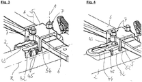
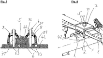
Die Ausführungsform von
- 22
- - Achsrohr- axle tube
- 44
- - Verbindungseinheit- Connection unit
- 55
- - erstes Klemmteil- First clamping part
- 66
- - Lenker- Handlebar
- 77
- - Krafteinheit- Force unit
- 88th
- - zweites Klemmteil- Second clamping part
- 4242
- - Halteelement- Holding element
- 4343
- - Eingriffsgeometrie- engagement geometry
- 4444
- - Einführbereich- insertion area
- 4545
- - Positionierhilfe- Positioning aid
- 5252
- - Ausformungen- Formations
- 5454
- - Vorsprung- Head Start
- 7171
- - erstes Kraftelement- first force element
- 7272
- - zweites Kraftelement- second force element
- 8181
- - erster Stützbereich- first support area
- 8282
- - zweiter Stützbereich- second support area
- AA
- - Kraftachse- Force axis
- RR
- - Rohrachse- Tube axis
Claims (15)
wobei sich das Achsrohr (2) längs einer Rohrachse (R) erstreckt,
wobei eine Verbindungseinheit (4) vorgesehen ist, welche ein Halteelement (42), ein erstes Klemmteil (5) und eine Krafteinheit (7) aufweist,
wobei das Halteelement (42) stoffschlüssig am Achsrohr (2) festlegbar ist,
wobei das erste Klemmteil (5) zumindest teilweise auf der dem Achsrohr (2) abgewandten Seite des Lenkers (6) anordenbar und mit dem Lenker (6) in kraftschlüssigen Eingriff bringbar ist,und
wobei die Krafteinheit (7) ausgelegt ist, eine Klemmkraft vom Halteelement (42) auf das erste Klemmteil (5) mittelbar oder unmittelbar zu übertragen.Axle system, in particular for use in commercial vehicles, comprising an axle tube (2) and a handlebar (6),
wherein the axle tube (2) extends along a tube axis (R),
wherein a connecting unit (4) is provided, which has a holding element (42), a first clamping part (5) and a force unit (7),
wherein the retaining element (42) can be fixed in a material-locking manner on the axle tube (2),
wherein the first clamping part (5) at least partially on the side facing away from the axle tube (2) of the handlebar (6) can be arranged and brought into frictional engagement with the handlebar (6), and
wherein the force unit (7) is designed to transmit a clamping force from the holding element (42) directly or indirectly to the first clamping part (5).
wobei die Klemmkraft parallel zu einer Kraftachse (A) wirkt, welche orthogonal zur Rohrachse (R) verläuft.An axle system according to claim 1,
wherein the clamping force acts in parallel to a force axis (A) which is orthogonal to the tube axis (R).
wobei die Krafteinheit (7) ein erstes Kraftelement (71) und ein zweites Kraftelement (72) aufweist,
wobei das erste Kraftelement (71) im Wesentlichen rotationssymmetrisch um die Kraftachse (A) ausgebildet ist.An axle system according to claim 2,
wherein the force unit (7) comprises a first force element (71) and a second force element (72),
wherein the first force element (71) is formed substantially rotationally symmetrical about the force axis (A).
wobei das Halteelement (42) eine Eingriffsgeometrie (43) aufweist, mit welcher die Krafteinheit (7) derart in Eingriff bringbar ist, dass zumindest in einer Richtung parallel zur Kraftachse (A) ein Formschluss zwischen der Krafteinheit (7) und dem Halteelement (42) hergestellt ist.Axle system according to one of the preceding claims,
wherein the holding element (42) has an engagement geometry (43), with which the force unit (7) can be brought into engagement such that a positive connection between the force unit (7) and the holding element (42) at least in one direction parallel to the force axis (A) ) is made.
wobei die Eingriffsgeometrie (43) ausgelegt ist, die Krafteinheit (7) an einer von zumindest zwei, längs der Rohrachse (R) voneinander beanstandeten Eingriffspositionen, festzulegen.An axle system according to claim 3,
wherein the engagement geometry (43) is designed to fix the power unit (7) at one of at least two engagement positions spaced apart from one another along the pipe axis (R).
wobei zwei Krafteinheiten (7) vorgesehen sind, die parallel zur Rohrachse (R) beabstandet voneinander je eine Klemmkraft auf das erste Klemmteil (5) übertragen.Axle system according to one of the preceding claims,
wherein two units of force (7) are provided, the spaced apart from the tube axis (R) spaced from each other a clamping force transmitted to the first clamping part (5).
wobei ein zweites Klemmteil (8) vorgesehen ist, welches die von der Krafteinheit (7) aufgebrachte Klemmkraft an das erste Klemmteil (5) überträgt, wobei das zweite Klemmteil (8) für elastische Verformung optimiert ist.Axle system according to one of the preceding claims,
wherein a second clamping part (8) is provided which transmits the clamping force applied by the power unit (7) to the first clamping part (5), the second clamping part (8) being optimized for elastic deformation.
wobei das zweite Klemmteil (8) als Federelement ausgebildet ist,
wobei das zweite Klemmteil (8) einen ersten Stützbereich (81) zur Abstützung an dem Halteelement (42) und einen zweiten Stützbereich (82) zur Abstützung am ersten Klemmteil (5) aufweist,
wobei zwischen zwei Stützbereichen (81, 82) die Krafteinheit (7) am zweiten Klemmteil (8) eingreift.An axle system according to claim 7,
wherein the second clamping part (8) is designed as a spring element,
wherein the second clamping part (8) has a first support region (81) for support on the holding element (42) and a second support region (82) for support on the first clamping part (5),
wherein between two support areas (81, 82) the force unit (7) engages the second clamping part (8).
wobei das zweite Klemmteil (8) zwei erste Stützbereiche (81) aufweist,
wobei zwischen den beiden ersten Stützbereichen (81) die Krafteinheit (7) eingreift.An axle system according to claim 8,
wherein the second clamping part (8) has two first support areas (81),
wherein the force unit (7) engages between the two first support areas (81).
wobei das zweite Klemmteil (8) W-förmig ausgebildet ist.An axle system according to claim 8 or 9,
wherein the second clamping part (8) is W-shaped.
wobei das erste Klemmteil (5) auf seiner dem Lenker (6) abgewandten Seite eine Ausformung (52) zum formschlüssigen Eingriff mit dem zweiten Klemmteil (8) aufweist.An axle system according to any one of claims 7 to 10,
wherein the first clamping part (5) on its side facing away from the handlebar (6) has a formation (52) for positive engagement with the second clamping part (8).
wobei das Halteelement (42) auf seiner dem Achsrohr (2) abgewandten Seite eine Positionierhilfe (44) zur Abstützung und zum formschlüssigen Eingriff des zweiten Klemmteils (8) aufweist.An axle system according to any one of claims 7 to 11,
wherein the holding element (42) on its side facing away from the axle tube (2) has a positioning aid (44) for the support and for the positive engagement of the second clamping part (8).
wobei die Eingriffsgeometrie (43) als Aussparung am Halteelement (42) ausgebildet,
wobei die Eingriffsgeometrie (43) ihre größte Erstreckung parallel zur Rohrachse (R) aufweist.An axle system according to any one of claims 4 to 12,
wherein the engagement geometry (43) is formed as a recess on the holding element (42),
wherein the engagement geometry (43) has its greatest extent parallel to the tube axis (R).
wobei die Eingriffsgeometrie (43) an einer ihrer kurzen Seiten offen ist, um die Krafteinheit (7) in die Eingriffsgeometrie (43) parallel zur Rohrachse (R) einschieben zu können.An axle system according to one of claims 4 to 13,
wherein the engagement geometry (43) on one of its short sides is open in order to be able to insert the force unit (7) into the engagement geometry (43) parallel to the tube axis (R).
Applications Claiming Priority (1)
| Application Number | Priority Date | Filing Date | Title |
|---|---|---|---|
| DE102016120732.2A DE102016120732B4 (en) | 2016-10-31 | 2016-10-31 | Axle system and method for producing an axle system |
Publications (3)
| Publication Number | Publication Date |
|---|---|
| EP3323646A2 true EP3323646A2 (en) | 2018-05-23 |
| EP3323646A3 EP3323646A3 (en) | 2018-07-25 |
| EP3323646B1 EP3323646B1 (en) | 2022-12-28 |
Family
ID=60080678
Family Applications (1)
| Application Number | Title | Priority Date | Filing Date |
|---|---|---|---|
| EP17195855.6A Active EP3323646B1 (en) | 2016-10-31 | 2017-10-11 | Axle system |
Country Status (2)
| Country | Link |
|---|---|
| EP (1) | EP3323646B1 (en) |
| DE (1) | DE102016120732B4 (en) |
Family Cites Families (10)
| Publication number | Priority date | Publication date | Assignee | Title |
|---|---|---|---|---|
| GB452059A (en) * | 1935-05-02 | 1936-08-17 | Robert Patterson | An improved axle connection for motor and other vehicles |
| DE1838603U (en) * | 1960-06-30 | 1961-09-28 | Ford Werke Ag | LEAF SPRING ATTACHMENT. |
| JPS6042042B2 (en) * | 1978-12-23 | 1985-09-20 | 日本発条株式会社 | Clamp device for stacked leaf springs |
| US5921570A (en) * | 1996-11-21 | 1999-07-13 | The Boler Company | Weld-on axle bracket with U-bolt connection |
| DE10029639C2 (en) * | 2000-06-15 | 2002-04-18 | Daimler Chrysler Ag | Coupling an axle beam to a vehicle leaf spring or a trailing arm |
| DE102007006972A1 (en) * | 2007-02-13 | 2008-08-14 | Bpw Bergische Achsen Kg | Axle integration for spring mounted vehicle axis has longitudinally extending axial body, which is provided with intersecting longitudinal links on its upper or lower side |
| US9114685B2 (en) | 2012-08-06 | 2015-08-25 | Hendrickson Usa, L.L.C. | Reduced weight axle coupling assembly for vehicle suspension systems |
| US8827289B2 (en) | 2012-08-06 | 2014-09-09 | Hendrickson Usa, L.L.C. | Reduced weight axle mounting assembly for vehicle suspension systems |
| US9446646B1 (en) * | 2015-05-29 | 2016-09-20 | Hendrickson Usa, L.L.C. | Spring seats and vehicle suspension systems incorporating such spring seats |
| DE102016103306A1 (en) * | 2016-02-25 | 2017-08-31 | Saf-Holland Gmbh | axle system |
-
2016
- 2016-10-31 DE DE102016120732.2A patent/DE102016120732B4/en active Active
-
2017
- 2017-10-11 EP EP17195855.6A patent/EP3323646B1/en active Active
Also Published As
| Publication number | Publication date |
|---|---|
| DE102016120732B4 (en) | 2019-06-13 |
| EP3323646A3 (en) | 2018-07-25 |
| DE102016120732A8 (en) | 2018-08-09 |
| DE102016120732A1 (en) | 2018-05-03 |
| EP3323646B1 (en) | 2022-12-28 |
Similar Documents
| Publication | Publication Date | Title |
|---|---|---|
| DE19754578B4 (en) | Clamping ring for connecting tubular components | |
| EP3414114B1 (en) | Axle unit | |
| EP3439902B1 (en) | Torsion bar spring | |
| EP3419837B1 (en) | Axle system | |
| DE10118696A1 (en) | Axle integration for sprung vehicle axles | |
| DE102008000936B4 (en) | Wheel suspension for a vehicle and connecting element for such a suspension | |
| DE102016120732B4 (en) | Axle system and method for producing an axle system | |
| EP2772372A1 (en) | Suspension for a commercial vehicle, axle body and method for manufacturing an axle body | |
| EP3442816B1 (en) | Frame system | |
| EP2711270B1 (en) | Frame for an industrial especially agricultural vehicle | |
| DE102017118812B4 (en) | Reinforced four-bar linkage | |
| EP2895334B1 (en) | Axle link coupling unit | |
| WO2016083174A1 (en) | Axle tie rod | |
| EP3085557B1 (en) | Reinforcing unit | |
| WO2021104561A1 (en) | Plate link chain for a continuously variable transmission and method for production of a plate link chain | |
| EP3702180A1 (en) | Running gear for a commercial vehicle, shell for same and arrangement of two shells forming a pair | |
| EP3191324B1 (en) | Axle unit | |
| WO2013092204A1 (en) | Mutual, detachable connection of two support sections of a variable-length construction support | |
| EP3802169B1 (en) | Axle mounting unit | |
| EP2332751B1 (en) | Lorry pivot bar with separated bar | |
| DE102013017210B3 (en) | Load transfer device for tensile and compressive forces and a chassis component comprising the load transfer device | |
| DE102005031209A1 (en) | Clamp for pipe connections comprises circular band whose ends can be fastened together by pair of bolts which pass through apertures in mountings which are stamped out of strip, so that apertures are tangential to it | |
| DE102009007923A1 (en) | Holding device, particularly for air pressure tank of trucks, has tank strap fixed on console, where weld-free connection is provided between console, tank strap and console screw connection | |
| EP2085296A1 (en) | Body component, vehicles and method for manufacturing a body component | |
| DE102019121667A1 (en) | Chassis for a commercial vehicle, shell therefor and arrangement of two shells forming a pair of shells therefor |
Legal Events
| Date | Code | Title | Description |
|---|---|---|---|
| PUAI | Public reference made under article 153(3) epc to a published international application that has entered the european phase |
Free format text: ORIGINAL CODE: 0009012 |
|
| STAA | Information on the status of an ep patent application or granted ep patent |
Free format text: STATUS: THE APPLICATION HAS BEEN PUBLISHED |
|
| AK | Designated contracting states |
Kind code of ref document: A2 Designated state(s): AL AT BE BG CH CY CZ DE DK EE ES FI FR GB GR HR HU IE IS IT LI LT LU LV MC MK MT NL NO PL PT RO RS SE SI SK SM TR |
|
| AX | Request for extension of the european patent |
Extension state: BA ME |
|
| PUAL | Search report despatched |
Free format text: ORIGINAL CODE: 0009013 |
|
| AK | Designated contracting states |
Kind code of ref document: A3 Designated state(s): AL AT BE BG CH CY CZ DE DK EE ES FI FR GB GR HR HU IE IS IT LI LT LU LV MC MK MT NL NO PL PT RO RS SE SI SK SM TR |
|
| AX | Request for extension of the european patent |
Extension state: BA ME |
|
| RIC1 | Information provided on ipc code assigned before grant |
Ipc: B60B 35/00 20060101ALI20180620BHEP Ipc: B60G 11/113 20060101AFI20180620BHEP Ipc: B60G 7/00 20060101ALI20180620BHEP |
|
| STAA | Information on the status of an ep patent application or granted ep patent |
Free format text: STATUS: REQUEST FOR EXAMINATION WAS MADE |
|
| 17P | Request for examination filed |
Effective date: 20190124 |
|
| RBV | Designated contracting states (corrected) |
Designated state(s): AL AT BE BG CH CY CZ DE DK EE ES FI FR GB GR HR HU IE IS IT LI LT LU LV MC MK MT NL NO PL PT RO RS SE SI SK SM TR |
|
| STAA | Information on the status of an ep patent application or granted ep patent |
Free format text: STATUS: EXAMINATION IS IN PROGRESS |
|
| 17Q | First examination report despatched |
Effective date: 20200323 |
|
| RIN1 | Information on inventor provided before grant (corrected) |
Inventor name: HARTMANN, MARK |
|
| STAA | Information on the status of an ep patent application or granted ep patent |
Free format text: STATUS: EXAMINATION IS IN PROGRESS |
|
| STAA | Information on the status of an ep patent application or granted ep patent |
Free format text: STATUS: EXAMINATION IS IN PROGRESS |
|
| GRAP | Despatch of communication of intention to grant a patent |
Free format text: ORIGINAL CODE: EPIDOSNIGR1 |
|
| STAA | Information on the status of an ep patent application or granted ep patent |
Free format text: STATUS: GRANT OF PATENT IS INTENDED |
|
| INTG | Intention to grant announced |
Effective date: 20220808 |
|
| GRAS | Grant fee paid |
Free format text: ORIGINAL CODE: EPIDOSNIGR3 |
|
| GRAA | (expected) grant |
Free format text: ORIGINAL CODE: 0009210 |
|
| STAA | Information on the status of an ep patent application or granted ep patent |
Free format text: STATUS: THE PATENT HAS BEEN GRANTED |
|
| AK | Designated contracting states |
Kind code of ref document: B1 Designated state(s): AL AT BE BG CH CY CZ DE DK EE ES FI FR GB GR HR HU IE IS IT LI LT LU LV MC MK MT NL NO PL PT RO RS SE SI SK SM TR |
|
| REG | Reference to a national code |
Ref country code: GB Ref legal event code: FG4D Free format text: NOT ENGLISH |
|
| REG | Reference to a national code |
Ref country code: CH Ref legal event code: EP |
|
| REG | Reference to a national code |
Ref country code: DE Ref legal event code: R096 Ref document number: 502017014260 Country of ref document: DE |
|
| REG | Reference to a national code |
Ref country code: AT Ref legal event code: REF Ref document number: 1540237 Country of ref document: AT Kind code of ref document: T Effective date: 20230115 |
|
| REG | Reference to a national code |
Ref country code: IE Ref legal event code: FG4D Free format text: LANGUAGE OF EP DOCUMENT: GERMAN |
|
| REG | Reference to a national code |
Ref country code: NL Ref legal event code: FP |
|
| REG | Reference to a national code |
Ref country code: LT Ref legal event code: MG9D |
|
| PG25 | Lapsed in a contracting state [announced via postgrant information from national office to epo] |
Ref country code: SE Free format text: LAPSE BECAUSE OF FAILURE TO SUBMIT A TRANSLATION OF THE DESCRIPTION OR TO PAY THE FEE WITHIN THE PRESCRIBED TIME-LIMIT Effective date: 20221228 Ref country code: NO Free format text: LAPSE BECAUSE OF FAILURE TO SUBMIT A TRANSLATION OF THE DESCRIPTION OR TO PAY THE FEE WITHIN THE PRESCRIBED TIME-LIMIT Effective date: 20230328 Ref country code: LT Free format text: LAPSE BECAUSE OF FAILURE TO SUBMIT A TRANSLATION OF THE DESCRIPTION OR TO PAY THE FEE WITHIN THE PRESCRIBED TIME-LIMIT Effective date: 20221228 Ref country code: FI Free format text: LAPSE BECAUSE OF FAILURE TO SUBMIT A TRANSLATION OF THE DESCRIPTION OR TO PAY THE FEE WITHIN THE PRESCRIBED TIME-LIMIT Effective date: 20221228 |
|
| PG25 | Lapsed in a contracting state [announced via postgrant information from national office to epo] |
Ref country code: RS Free format text: LAPSE BECAUSE OF FAILURE TO SUBMIT A TRANSLATION OF THE DESCRIPTION OR TO PAY THE FEE WITHIN THE PRESCRIBED TIME-LIMIT Effective date: 20221228 Ref country code: LV Free format text: LAPSE BECAUSE OF FAILURE TO SUBMIT A TRANSLATION OF THE DESCRIPTION OR TO PAY THE FEE WITHIN THE PRESCRIBED TIME-LIMIT Effective date: 20221228 Ref country code: HR Free format text: LAPSE BECAUSE OF FAILURE TO SUBMIT A TRANSLATION OF THE DESCRIPTION OR TO PAY THE FEE WITHIN THE PRESCRIBED TIME-LIMIT Effective date: 20221228 Ref country code: GR Free format text: LAPSE BECAUSE OF FAILURE TO SUBMIT A TRANSLATION OF THE DESCRIPTION OR TO PAY THE FEE WITHIN THE PRESCRIBED TIME-LIMIT Effective date: 20230329 |
|
| P01 | Opt-out of the competence of the unified patent court (upc) registered |
Effective date: 20230505 |
|
| PG25 | Lapsed in a contracting state [announced via postgrant information from national office to epo] |
Ref country code: SM Free format text: LAPSE BECAUSE OF FAILURE TO SUBMIT A TRANSLATION OF THE DESCRIPTION OR TO PAY THE FEE WITHIN THE PRESCRIBED TIME-LIMIT Effective date: 20221228 Ref country code: RO Free format text: LAPSE BECAUSE OF FAILURE TO SUBMIT A TRANSLATION OF THE DESCRIPTION OR TO PAY THE FEE WITHIN THE PRESCRIBED TIME-LIMIT Effective date: 20221228 Ref country code: PT Free format text: LAPSE BECAUSE OF FAILURE TO SUBMIT A TRANSLATION OF THE DESCRIPTION OR TO PAY THE FEE WITHIN THE PRESCRIBED TIME-LIMIT Effective date: 20230428 Ref country code: ES Free format text: LAPSE BECAUSE OF FAILURE TO SUBMIT A TRANSLATION OF THE DESCRIPTION OR TO PAY THE FEE WITHIN THE PRESCRIBED TIME-LIMIT Effective date: 20221228 Ref country code: EE Free format text: LAPSE BECAUSE OF FAILURE TO SUBMIT A TRANSLATION OF THE DESCRIPTION OR TO PAY THE FEE WITHIN THE PRESCRIBED TIME-LIMIT Effective date: 20221228 Ref country code: CZ Free format text: LAPSE BECAUSE OF FAILURE TO SUBMIT A TRANSLATION OF THE DESCRIPTION OR TO PAY THE FEE WITHIN THE PRESCRIBED TIME-LIMIT Effective date: 20221228 |
|
| PG25 | Lapsed in a contracting state [announced via postgrant information from national office to epo] |
Ref country code: SK Free format text: LAPSE BECAUSE OF FAILURE TO SUBMIT A TRANSLATION OF THE DESCRIPTION OR TO PAY THE FEE WITHIN THE PRESCRIBED TIME-LIMIT Effective date: 20221228 Ref country code: PL Free format text: LAPSE BECAUSE OF FAILURE TO SUBMIT A TRANSLATION OF THE DESCRIPTION OR TO PAY THE FEE WITHIN THE PRESCRIBED TIME-LIMIT Effective date: 20221228 Ref country code: IS Free format text: LAPSE BECAUSE OF FAILURE TO SUBMIT A TRANSLATION OF THE DESCRIPTION OR TO PAY THE FEE WITHIN THE PRESCRIBED TIME-LIMIT Effective date: 20230428 Ref country code: AL Free format text: LAPSE BECAUSE OF FAILURE TO SUBMIT A TRANSLATION OF THE DESCRIPTION OR TO PAY THE FEE WITHIN THE PRESCRIBED TIME-LIMIT Effective date: 20221228 |
|
| REG | Reference to a national code |
Ref country code: DE Ref legal event code: R097 Ref document number: 502017014260 Country of ref document: DE |
|
| PG25 | Lapsed in a contracting state [announced via postgrant information from national office to epo] |
Ref country code: DK Free format text: LAPSE BECAUSE OF FAILURE TO SUBMIT A TRANSLATION OF THE DESCRIPTION OR TO PAY THE FEE WITHIN THE PRESCRIBED TIME-LIMIT Effective date: 20221228 |
|
| PLBE | No opposition filed within time limit |
Free format text: ORIGINAL CODE: 0009261 |
|
| STAA | Information on the status of an ep patent application or granted ep patent |
Free format text: STATUS: NO OPPOSITION FILED WITHIN TIME LIMIT |
|
| PGFP | Annual fee paid to national office [announced via postgrant information from national office to epo] |
Ref country code: NL Payment date: 20231023 Year of fee payment: 7 |
|
| 26N | No opposition filed |
Effective date: 20230929 |
|
| PGFP | Annual fee paid to national office [announced via postgrant information from national office to epo] |
Ref country code: GB Payment date: 20231025 Year of fee payment: 7 |
|
| PG25 | Lapsed in a contracting state [announced via postgrant information from national office to epo] |
Ref country code: SI Free format text: LAPSE BECAUSE OF FAILURE TO SUBMIT A TRANSLATION OF THE DESCRIPTION OR TO PAY THE FEE WITHIN THE PRESCRIBED TIME-LIMIT Effective date: 20221228 |
|
| PGFP | Annual fee paid to national office [announced via postgrant information from national office to epo] |
Ref country code: FR Payment date: 20231023 Year of fee payment: 7 Ref country code: DE Payment date: 20230817 Year of fee payment: 7 |