EP3323565A1 - Method and device for commissioning a multiple axis system - Google Patents
Method and device for commissioning a multiple axis system Download PDFInfo
- Publication number
- EP3323565A1 EP3323565A1 EP16199731.7A EP16199731A EP3323565A1 EP 3323565 A1 EP3323565 A1 EP 3323565A1 EP 16199731 A EP16199731 A EP 16199731A EP 3323565 A1 EP3323565 A1 EP 3323565A1
- Authority
- EP
- European Patent Office
- Prior art keywords
- axis system
- axis
- camera
- components
- markers
- Prior art date
- Legal status (The legal status is an assumption and is not a legal conclusion. Google has not performed a legal analysis and makes no representation as to the accuracy of the status listed.)
- Granted
Links
- 238000000034 method Methods 0.000 title claims abstract description 38
- 230000003287 optical effect Effects 0.000 claims abstract description 42
- 230000035515 penetration Effects 0.000 claims abstract description 4
- 239000003550 marker Substances 0.000 claims description 44
- 230000001681 protective effect Effects 0.000 claims description 10
- 230000003190 augmentative effect Effects 0.000 claims description 8
- 238000012552 review Methods 0.000 claims description 3
- 238000004590 computer program Methods 0.000 claims description 2
- 238000011156 evaluation Methods 0.000 claims description 2
- 238000012545 processing Methods 0.000 claims description 2
- 238000001454 recorded image Methods 0.000 claims 1
- 238000001514 detection method Methods 0.000 description 6
- 230000006870 function Effects 0.000 description 3
- 238000012800 visualization Methods 0.000 description 3
- 230000001133 acceleration Effects 0.000 description 2
- 230000001419 dependent effect Effects 0.000 description 2
- 238000004519 manufacturing process Methods 0.000 description 2
- 238000012544 monitoring process Methods 0.000 description 2
- 238000012795 verification Methods 0.000 description 2
- 241000282412 Homo Species 0.000 description 1
- 208000027418 Wounds and injury Diseases 0.000 description 1
- 238000013459 approach Methods 0.000 description 1
- 230000005540 biological transmission Effects 0.000 description 1
- 238000004364 calculation method Methods 0.000 description 1
- 230000003931 cognitive performance Effects 0.000 description 1
- 238000004891 communication Methods 0.000 description 1
- 230000006378 damage Effects 0.000 description 1
- 239000011521 glass Substances 0.000 description 1
- 208000014674 injury Diseases 0.000 description 1
- 238000003754 machining Methods 0.000 description 1
- 238000003801 milling Methods 0.000 description 1
- 238000004806 packaging method and process Methods 0.000 description 1
- 238000012360 testing method Methods 0.000 description 1
- 230000009466 transformation Effects 0.000 description 1
- 230000001960 triggered effect Effects 0.000 description 1
- 230000000007 visual effect Effects 0.000 description 1
Images
Classifications
-
- G—PHYSICS
- G06—COMPUTING; CALCULATING OR COUNTING
- G06T—IMAGE DATA PROCESSING OR GENERATION, IN GENERAL
- G06T7/00—Image analysis
- G06T7/0002—Inspection of images, e.g. flaw detection
- G06T7/0004—Industrial image inspection
-
- B—PERFORMING OPERATIONS; TRANSPORTING
- B25—HAND TOOLS; PORTABLE POWER-DRIVEN TOOLS; MANIPULATORS
- B25J—MANIPULATORS; CHAMBERS PROVIDED WITH MANIPULATION DEVICES
- B25J9/00—Programme-controlled manipulators
- B25J9/16—Programme controls
- B25J9/1656—Programme controls characterised by programming, planning systems for manipulators
- B25J9/1664—Programme controls characterised by programming, planning systems for manipulators characterised by motion, path, trajectory planning
- B25J9/1666—Avoiding collision or forbidden zones
-
- B—PERFORMING OPERATIONS; TRANSPORTING
- B25—HAND TOOLS; PORTABLE POWER-DRIVEN TOOLS; MANIPULATORS
- B25J—MANIPULATORS; CHAMBERS PROVIDED WITH MANIPULATION DEVICES
- B25J9/00—Programme-controlled manipulators
- B25J9/16—Programme controls
-
- B—PERFORMING OPERATIONS; TRANSPORTING
- B25—HAND TOOLS; PORTABLE POWER-DRIVEN TOOLS; MANIPULATORS
- B25J—MANIPULATORS; CHAMBERS PROVIDED WITH MANIPULATION DEVICES
- B25J9/00—Programme-controlled manipulators
- B25J9/16—Programme controls
- B25J9/1656—Programme controls characterised by programming, planning systems for manipulators
- B25J9/1671—Programme controls characterised by programming, planning systems for manipulators characterised by simulation, either to verify existing program or to create and verify new program, CAD/CAM oriented, graphic oriented programming systems
-
- G—PHYSICS
- G05—CONTROLLING; REGULATING
- G05B—CONTROL OR REGULATING SYSTEMS IN GENERAL; FUNCTIONAL ELEMENTS OF SUCH SYSTEMS; MONITORING OR TESTING ARRANGEMENTS FOR SUCH SYSTEMS OR ELEMENTS
- G05B19/00—Programme-control systems
- G05B19/02—Programme-control systems electric
- G05B19/04—Programme control other than numerical control, i.e. in sequence controllers or logic controllers
- G05B19/05—Programmable logic controllers, e.g. simulating logic interconnections of signals according to ladder diagrams or function charts
- G05B19/058—Safety, monitoring
-
- G—PHYSICS
- G05—CONTROLLING; REGULATING
- G05B—CONTROL OR REGULATING SYSTEMS IN GENERAL; FUNCTIONAL ELEMENTS OF SUCH SYSTEMS; MONITORING OR TESTING ARRANGEMENTS FOR SUCH SYSTEMS OR ELEMENTS
- G05B19/00—Programme-control systems
- G05B19/02—Programme-control systems electric
- G05B19/18—Numerical control [NC], i.e. automatically operating machines, in particular machine tools, e.g. in a manufacturing environment, so as to execute positioning, movement or co-ordinated operations by means of programme data in numerical form
- G05B19/414—Structure of the control system, e.g. common controller or multiprocessor systems, interface to servo, programmable interface controller
-
- G—PHYSICS
- G06—COMPUTING; CALCULATING OR COUNTING
- G06T—IMAGE DATA PROCESSING OR GENERATION, IN GENERAL
- G06T19/00—Manipulating 3D models or images for computer graphics
- G06T19/006—Mixed reality
-
- G—PHYSICS
- G06—COMPUTING; CALCULATING OR COUNTING
- G06T—IMAGE DATA PROCESSING OR GENERATION, IN GENERAL
- G06T7/00—Image analysis
- G06T7/20—Analysis of motion
-
- G—PHYSICS
- G06—COMPUTING; CALCULATING OR COUNTING
- G06T—IMAGE DATA PROCESSING OR GENERATION, IN GENERAL
- G06T7/00—Image analysis
- G06T7/50—Depth or shape recovery
-
- G—PHYSICS
- G06—COMPUTING; CALCULATING OR COUNTING
- G06T—IMAGE DATA PROCESSING OR GENERATION, IN GENERAL
- G06T7/00—Image analysis
- G06T7/70—Determining position or orientation of objects or cameras
- G06T7/73—Determining position or orientation of objects or cameras using feature-based methods
-
- G—PHYSICS
- G05—CONTROLLING; REGULATING
- G05B—CONTROL OR REGULATING SYSTEMS IN GENERAL; FUNCTIONAL ELEMENTS OF SUCH SYSTEMS; MONITORING OR TESTING ARRANGEMENTS FOR SUCH SYSTEMS OR ELEMENTS
- G05B2219/00—Program-control systems
- G05B2219/10—Plc systems
- G05B2219/13—Plc programming
- G05B2219/13098—Nc function to control axis, written in C or not
-
- G—PHYSICS
- G05—CONTROLLING; REGULATING
- G05B—CONTROL OR REGULATING SYSTEMS IN GENERAL; FUNCTIONAL ELEMENTS OF SUCH SYSTEMS; MONITORING OR TESTING ARRANGEMENTS FOR SUCH SYSTEMS OR ELEMENTS
- G05B2219/00—Program-control systems
- G05B2219/30—Nc systems
- G05B2219/32—Operator till task planning
- G05B2219/32014—Augmented reality assists operator in maintenance, repair, programming, assembly, use of head mounted display with 2-D 3-D display and voice feedback, voice and gesture command
-
- G—PHYSICS
- G05—CONTROLLING; REGULATING
- G05B—CONTROL OR REGULATING SYSTEMS IN GENERAL; FUNCTIONAL ELEMENTS OF SUCH SYSTEMS; MONITORING OR TESTING ARRANGEMENTS FOR SUCH SYSTEMS OR ELEMENTS
- G05B2219/00—Program-control systems
- G05B2219/30—Nc systems
- G05B2219/37—Measurements
- G05B2219/37009—Calibration of vision system, camera, adapt light level
-
- G—PHYSICS
- G05—CONTROLLING; REGULATING
- G05B—CONTROL OR REGULATING SYSTEMS IN GENERAL; FUNCTIONAL ELEMENTS OF SUCH SYSTEMS; MONITORING OR TESTING ARRANGEMENTS FOR SUCH SYSTEMS OR ELEMENTS
- G05B2219/00—Program-control systems
- G05B2219/30—Nc systems
- G05B2219/39—Robotics, robotics to robotics hand
- G05B2219/39094—Interference checking between robot and fixture
-
- G—PHYSICS
- G05—CONTROLLING; REGULATING
- G05B—CONTROL OR REGULATING SYSTEMS IN GENERAL; FUNCTIONAL ELEMENTS OF SUCH SYSTEMS; MONITORING OR TESTING ARRANGEMENTS FOR SUCH SYSTEMS OR ELEMENTS
- G05B2219/00—Program-control systems
- G05B2219/30—Nc systems
- G05B2219/39—Robotics, robotics to robotics hand
- G05B2219/39449—Pendant, pda displaying camera images overlayed with graphics, augmented reality
-
- G—PHYSICS
- G05—CONTROLLING; REGULATING
- G05B—CONTROL OR REGULATING SYSTEMS IN GENERAL; FUNCTIONAL ELEMENTS OF SUCH SYSTEMS; MONITORING OR TESTING ARRANGEMENTS FOR SUCH SYSTEMS OR ELEMENTS
- G05B2219/00—Program-control systems
- G05B2219/30—Nc systems
- G05B2219/40—Robotics, robotics mapping to robotics vision
- G05B2219/40479—Use graphic display, layout of robot path, obstacles to indicate interference
-
- G—PHYSICS
- G06—COMPUTING; CALCULATING OR COUNTING
- G06T—IMAGE DATA PROCESSING OR GENERATION, IN GENERAL
- G06T2207/00—Indexing scheme for image analysis or image enhancement
- G06T2207/30—Subject of image; Context of image processing
- G06T2207/30108—Industrial image inspection
- G06T2207/30164—Workpiece; Machine component
-
- G—PHYSICS
- G06—COMPUTING; CALCULATING OR COUNTING
- G06T—IMAGE DATA PROCESSING OR GENERATION, IN GENERAL
- G06T2207/00—Indexing scheme for image analysis or image enhancement
- G06T2207/30—Subject of image; Context of image processing
- G06T2207/30204—Marker
- G06T2207/30208—Marker matrix
-
- G—PHYSICS
- G06—COMPUTING; CALCULATING OR COUNTING
- G06T—IMAGE DATA PROCESSING OR GENERATION, IN GENERAL
- G06T2210/00—Indexing scheme for image generation or computer graphics
- G06T2210/12—Bounding box
Definitions
- the invention relates to a method and a device for starting up a multi-axis system.
- the multi-axis system includes as components a number of segments connected by respective hinges and movable in one or more axes, and a tool connected to one of the segments and movable and controllable to a predetermined position.
- the multi-axis system is a work space in which a residence and / or movement of the components is allowed, and associated with at least one shelter in which an intrusion of the components is not allowed.
- Multi-axis systems are universal, programmable machines for handling, assembling or machining workpieces. These are also called (industrial) robots. These are designed for use in industrial environments. Once programmed, such a multi-axis system is able to autonomously perform a workflow, or to vary the execution of a task, depending on sensor information.
- a prerequisite for the correct and safe functioning of such a multi-axis system is the definition of enveloping bodies for the moving components as well as the correct definition of protective and working spaces.
- Envelopes may have different geometric dimensions and shapes.
- Typical enveloping bodies used are e.g. Spheres, cuboids or structures composed of several cuboids.
- the definition of enveloping bodies as well as the definition of protective and working spaces enables a cooperation of a multi-axis system with humans, as long as it is ensured that no enveloping body of a component of the multi-axis system penetrates into a shelter. Failure to define these bodies will result in e.g. the penetration of an enveloping body into a protected area is not recognized, so that a safety function is erroneously not triggered.
- a method for starting up a multi-axis system includes as components a number of segments and a tool.
- the number of segments is connected in pairs via respective joints and is movable by a control in one or more axes.
- the tool is connected to one of the segments and moved by the controller to a predetermined position and controllable.
- the multi-axis system is assigned a workspace in which a residence and / or movement of the components of the multi-axis system is permitted. Further, the multi-axis system is associated with at least one shelter in which an intrusion of the components is not allowed.
- a plurality of optical markers are arranged in the environment of the multi-axis system to enable an augmented reality (AR) system, the position and orientation of a camera system comprising at least one camera and the multi-axis system detected from an environment to determine.
- AR augmented reality
- a camera system comprising at least one camera
- the multi-axis system detected from an environment to determine.
- an enveloping body is defined and assigned thereto, wherein an enveloping body assigned to a component encloses the associated component, in particular completely.
- a check of the defined enveloping body with respect to the working space and the shelter by means of the AR system is performed by calculating the position of the enveloping bodies in a first, global coordinate system (world coordinate system) and in a second coordinate system during a movement of the multi-axis system in space a position and orientation of the camera system (camera coordinate system) is transformed, wherein the enveloping bodies transformed into the second coordinate system are visualized together with an image captured by the camera system in the AR system.
- the proposed method enables a functionally secure definition and verification of the enveloping body as well as the protective and working areas with the aid of the AR system. Any errors in the definition of the enveloping body or in the assignment of an enveloping body to a respective component of the multi-axis system can be detected in a simple and rapid manner by the possibility of visual checking in the AR system. In addition, the proposed method is less prone to errors of reasoning.
- position coordinates of the optical markers in the first global coordinate system are determined and stored in the controller.
- the Determining the position coordinates can be done in different ways.
- a TCP (Tool Center Point) of the tool of the multi-axis system is moved to a respective optical marker to determine the position coordinates of the optical markers. Further, the position coordinates of the TCP known to the controller are determined and stored as the position coordinates of the optical marker.
- the tool in particular with its TCP, is moved to the location of the optical marker. This movement can be done manually in a so-called jogging mode or automatically. Since the control of the multi-axis system in a manual or automatic movement of the tool knows the position coordinates of the tool or its TCP, the position of the optical marker and its position coordinates can be determined.
- a mark applied to the tool, in particular the TCP, and the optical marker currently being processed are detected by the AR system.
- a distance between the marker and the optical marker is determined.
- the position of the tool is iteratively changed until the distance is minimal.
- the position coordinates known to the controller of the tool, in particular of the TCP are determined and stored at a minimum distance as the position coordinates of the optical marker.
- the TCP is a reference point intended in the field of multi-axis systems and known to the person skilled in the art, which is located at a suitable location on the tool. To describe the position of the multi-axis system tool, it is sufficient to define the position and orientation of the TCP in space, ie in the global coordinate system.
- the second variant for determining the position coordinates makes it possible to automatically determine the position coordinates of the respective optical markers.
- An iterative search method is used in which the tool or the TCP is moved until the distance between the tool or TCP and the currently considered optical marker becomes minimal. This procedure is repeated for all optical markers.
- the mark attached to the tool or TCP may be an optical mark which is visually detectable by the AR system.
- the marking may alternatively be a distance measuring unit. This can e.g. a laser gauge that measures the distance to a point in front of it. This may, for example, include a radio interface to transmit a distance measured between the tag and the subject optical marker to the AR system. Based on the transmitted distance, the controller can then make a targeted movement of the multi-axis system in order to minimize the distance in iterative steps to the respectively considered optical marker.
- the determination of the position coordinates of the respective optical markers takes place, in turn, from the knowledge of the position coordinates of the TCP at the minimum distance between the considered optical marker and the tool or TCP.
- the distance is determined by the distance measuring unit and transmitted to the AR system or the controller for further evaluation.
- a further embodiment provides that the position coordinates of the optical markers are transmitted to the AR system, wherein the AR system determines the position and orientation of the camera system in the first, global coordinate system on the basis of the optically detected markers and the assigned position coordinates.
- a respective enveloping body provision may be made for a number of position coordinates of an auxiliary marker temporarily arranged in the surroundings of the multi-axis system to be detected by the camera system and its position coordinates to be determined by the AR system.
- the auxiliary marker for example, support points of the enveloping bodies (for example corner points in the case of a cuboid or a plurality of points on the surface of a sphere) can be defined.
- a user holds the auxiliary marker to the desired position of a base.
- the position coordinates are determined and stored by the AR system. Once all interpolation points have been entered, the enveloping body can be calculated and stored. In the same way, the protection and work spaces can be defined.
- a respective enveloping body this may be generated according to the type and dimension of the component and iteratively changed in terms of position and orientation in the AR system by means of an auxiliary marker arranged in the environment of the multi-axis system until it envelopes the associated component.
- suitable enveloping bodies are defined and generated in advance for each component. Their exact location or size can then be made with the help of the AR system with the help of the aforementioned auxiliary marker.
- Another embodiment provides that in the AR system, the work space or at least a shelter be visualized. With the aid of the AR system, it can then be checked whether the previously defined and stored enveloping bodies, protective and working spaces correspond to reality. It would be erroneous, for example, if an envelope is too small, and a part of the multi-axis system is not shrouded. This check can be done manually, ie by viewing the augmented camera image. Alternatively, the exam can also be automatic respectively. If, for example, the multi-axis system is painted in orange, but the superimposed enveloping bodies are colored blue in the visualization, no blue pixel may appear in the augmented image. This check can be done by an image recognition software.
- one or more markers must be recognizable in the image data captured by the camera system. Under certain circumstances, there may be no or too little optical markers in the data recorded by the camera system. In this case, it is convenient to arrange a number of other temporary markers in the vicinity of the multi-axis system, wherein the position coordinates include the number of temporary markers by image-processing an image containing the number of temporary markers and the plurality of optical markers are to be determined. In order to be able to thus determine the position coordinates of the temporary markers, it is necessary to position and align the camera system in advance in such a way that both the number of temporary markers and a sufficient number of optical markers are contained in the image data.
- optical markers mentioned in this specification may e.g. special stickers, special items or the like.
- optical markers may be defined as succinct edges and / or corners of the surroundings as optical markers.
- the invention also proposes a computer program product that can be directly loaded into the internal memory of a digital computer and includes software code portions that perform the steps of the method described in this specification when the product is run on a computer.
- a computer may in this sense be the entirety of the described controller as well as the AR system.
- a device for starting up a multi-axis system includes as components a number of segments and a tool.
- the number of segments is connected via respective hinges and movable in one or more axes.
- the tool is connected to one of the segments and movable to a predetermined position and controllable.
- the multi-axis system is a work space in which a residence and / or movement of the components is allowed, and associated with at least one shelter in which an intrusion of the components is not allowed.
- the device comprises a controller for controlling the components of the multi-axis system.
- the device comprises a camera system with at least one camera, which detects the multi-axis system from an environment.
- the device includes an augmented reality (AR) system that captures and processes the image captured by the camera system.
- the AR system is configured to define and to assign an enveloping body to each of the components, wherein an enveloping body assigned to a component includes the assigned component, in particular completely.
- the apparatus includes a plurality of optical markers in the vicinity of the multi-axis system to enable the AR system to determine the position and orientation of the camera system sensing the environment of the multi-axis system.
- the device comprises an output device of the AR system, which is set up to carry out a check of the defined enveloping bodies with respect to the working space and the protective space, in which the position of the enveloping bodies in a first, global coordinate system is calculated during a movement of the multi-axis system in space and transformed into a second coordinate system according to a position and orientation of the camera system.
- the enveloping bodies transformed into the second coordinate system are used together with that of visualized in the output device of the AR system.
- the device according to the invention has the same advantages as described above in connection with the method according to the invention.
- the device may comprise further means for carrying out the method.
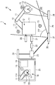
- Fig. 1 shows a schematic representation of an inventive device 1 for commissioning a multi-axis system 10.
- the multi-axis system 10 may be, for example, an industrial robot, a production or packaging machine, a CNC milling machine, a loading crane or the like.
- a multi-axis system is also to be understood as meaning a production cell with a plurality of such machines.
- the multi-axis system 10 comprises a number of segments 11, which are connected in pairs via a joint 12. At a free end of a last segment 11, a tool 13 with a TCP (Tool Center Point) 14 is arranged by way of example.
- TCP Tool Center Point
- the TCP is a reference point located at a suitable location on the tool 13.
- the kinematics of the multi-axis system 10 is controlled by a controller 20.
- the controller for example a programmable logic controller (PLC)
- PLC programmable logic controller
- the multi-axis system 10 includes functionally safe sensors (not shown) for detecting the axial positions of the kinematics, ie the individual segments 11 and joints 12.
- the values of the functionally safe sensors are provided by a functionally safe control (so-called F-PLC) on which a functionally safe program runs.
- F-PLC functionally safe control
- the functionally safe controller 21 also calculates the current position of the kinematics enveloping body in a so-called.
- World coordinate system It checks whether there is an overlap between later-described enveloping bodies and the protective spaces, or whether an enveloping body leaves the working space.
- the function of the functionally safe controller 21 is to monitor compliance with a maximum speed during manual multi-axis system operation that may be necessary to perform a method step during multi-system commissioning. If one of these cases occurs, a safety function is executed, eg stopping the kinematics.
- controller 20 and the functionally safe controller 21 are shown as separate components, the controller 20 and the functionally safe controller 21 may also be implemented by a single controller.
- the device comprises a programming device 22 which is connected to the controller and / or the functionally safe controller 21 in order to load a program or parameter into the controller 20 or functionally safe controller 21 and to read out values calculated therefrom.
- the device 1 further comprises a camera system 26.
- the camera system 26 comprises a first camera 27 which detects the environment of the multi-axis system 10. The image captured by the first camera 27 is used to determine the position of the camera system and the orientation of the camera system 26.
- the camera system 26 includes an optional second camera 28.
- the optional second camera 28 serves to provide a particular cutout (in this description also referred to as a scene). If the camera system also includes the optional second camera 28 in addition to the first camera 27, these are connected to one another by means of a rigid connection 29. As a result, the position and orientation of the first and the second camera 27, 28 are known to each other.
- the use of two cameras 27, 28 shown in this embodiment allows observation of the scene from different angles.
- a detection range of the first camera 27 is denoted by 27E and a detection range of the second camera 28 is indicated by 28E. It is readily apparent that the detection area 27E detects the multi-axis system 10 as a whole, while the detection area of the 28E of the second camera 28 is selected such that, in particular, the tool 13 and a part of the segment holding the tool 11 are detected.
- the use of a second camera also reduces the risk of obscuring portions of the multi-axis system 10.
- the device 1 further comprises an AR system 23, which reads in the image captured by the first camera 27 and determines the position of the first camera 27 or of the camera pair by evaluating the image information.
- the image of the second camera 28 and information from the functionally safe controller 21 are also read by the AR system, combined with each other and forwarded to an output device 25 for visualization.
- the AR system 23 may be implemented in software and executed on the programmer 22. Alternatively, the AR system 23 may be implemented as a standalone component as shown. In this case, there is a communication link to the programmer 22.
- an output device 25 which, in this embodiment, displays the image captured by the second camera 28.
- the output device 25 may be a computer, such as a PC, a laptop, a tablet, a smartphone, but also an AR glasses and any other device for displaying two-dimensional or three-dimensional images.
- various dispensers for example one during the definition of the enveloping bodies described in more detail below, and another during the test.
- the first and the second camera 27, 28, the output device 25 may be combined with the AR system 23 in a common device.
- markers 15 are distributed.
- the markers 15 can be optical markers, such as stickers, but also objects with a specific shape and / or color. However, in general, selected edges and / or corners or other significant components of the multi-axis system 10 and / or the environment of the multi-axis system can also be used as optical markers 15. It is useful if the markers 15 are arranged evenly in the room.
- the AR system 23 it is possible for the AR system 23 to make an exact position determination as well as a determination of the position and orientation of the camera system 26. If the AR system does not require markers for position determination, since other components and / or technical units are used for position determination, the markers 15 need not be optically detectable by the camera system 26.
- a first step several of the markers 15 are arranged at suitable locations, which enable the AR system 23 to locate the camera system 26 exactly.
- the locations of the placement of the markers 15 are selected such that the markers 15 can be detected from as many viewing angles as possible for the camera system 26.
- the position of the markers 15 in a global coordinate system of the kinematics of the multi-axis system 10 is determined. This is done e.g. in that the TCP 14 of the tool 13 is moved to a respective marker 15 and the position is confirmed by the input device 24.
- the Cartesian coordinates of the respective marker 15 can be reliably determined.
- the markers 15 are then determined in the global coordinate system of the multi-axis system 10.
- Moving the TCP to a respective marker 15 can be done manually, for example, in so-called jog mode. Similarly, moving the TCP to a particular marker can be done automatically. For this purpose, a mark is applied to the TCP 14 of the tool 12 so that the AR system 23 is enabled to calculate the distance of the TCP 14 to the respective markers 15. For a given marker 15, the segments 11 of the multi-axis system are moved as part of a search process until this distance becomes minimal. This procedure is repeated for all markers 15.
- a laser range meter with radio interface (not shown) to the TCP 14.
- the AR system 23 detects the laser spot in Camera image, eg by switching on / off a laser of the distance measuring device and observing the pixels in the camera image.
- the AR system 23 detects the marker 15 and calculates the distance between the laser spot and the marker 15 concerned.
- the AR system 23 wirelessly reads the measured distance from the range finder and combines it with the coordinates of the TCP from the controller 20 of the multi-axis system 10.
- the controller 20 then moves the kinematics of the multi-axis system 10 according to the calculated distance until the laser spot is superimposed on the marker 15.
- This process is carried out until all markers 15 in the coordinate system of the multi-axis system 10 have been measured.
- the positional coordinates of the markers 15 are transmitted from the functionally safe controller 21 to the AR system 23.
- the AR system 23 is thereby able to select from a moving image of the camera system 26 containing the markers 15. to close the position and direction of the camera system in the global coordinate system.
- the previously detected markers 15 are not sufficient to determine the position and direction of the camera system 26, for example because not all or not enough markers 15 are visible from all necessary viewing angles, further temporary markers can be arranged in the environment of the multi-axis system 10.
- the position of the temporary markers (not shown) can be determined by the AR system 23 with the aid of the previous markers 15.
- a calibration of the temporary markers is not required.
- existing reference points e.g. Corner points of immovable objects or the like can be used as temporary markers.
- the enveloping body is defined for the components (segments 11, joints 12, tool 13) of the multi-axis system 10.
- an enveloping body 11H, 13H may have the shape of a cuboid defined by a number of vertices. If the enveloping body is a sphere, then the sphere can be defined by at least three points on the sphere surface.
- a user holds the auxiliary marker to the desired position of a fulcrum and activates the input device. This causes the AR system 23 to calculate the position of the auxiliary marker. The calculation is based on the image data and the marker 15 contained in the image data whose position is known in the first, global coordinate system.
- the enveloping body 11H, 13H is calculated and stored in the functionally safe controller 21. This is repeated for all components of the multi-axis system 10.
- a respective enveloping body 11H, 13H assigned to a component 11, 13 surrounds the component in its entirety.
- an enveloping body can be defined, e.g. Cuboid, sphere or similar.
- the enveloping body is interactively placed over the input device and controlled by the output device by moving the auxiliary marker to the appropriate position and orientation. With the help of the input device 24, the correct position and orientation is confirmed. Subsequently, the dimension, position and orientation of the placed enveloping body can be adjusted in a similar manner until a desired accuracy is achieved.
- the enveloping bodies are divided into shelters, working spaces and enveloping bodies.
- the enveloping bodies are assigned to the individual components (segments 11, tool 13, joints 12) of the kinematics of the multi-axis system 10. It is understood that the protective or Workspaces may have been created in the course of defining the body or in advance.
- the checking of the defined enveloping bodies 11H, 13H takes place in that the functionally safe control 21 calculates the position of the enveloping body, possibly in dependence on current positions of the segments 11, 13 of the multi-axis system 10.
- the AR system 23 reads in the current position and orientation of the enveloping bodies 11H, 13H and the shelter 19 from the functionally safe controller 21. Subsequently, the AR system 23 transforms the enveloping bodies 11H, 13H and the guard space 19, respectively, according to the position and orientation of the camera system 26.
- the enveloping bodies 11H, 13H and the working space (s) 18 and the guard space (s) 19 are combined with the actual image of the camera system 26 overlaid and displayed on the output device 25.
- the working space is only indicated schematically by the reference numeral 18.
- the enveloping body 11H for the segment 11 and 13H for the tool 13 are each shown as a cuboid.
- a shelter 19 exemplified in the shape of a cuboid, is visualized.
- the respective components of the multi-axis system 10. With the help of the AR system can then be checked whether the previously defined and stored enveloping body, protective and working spaces with the Reality match.
- the camera system 26 can be moved to view the enveloping bodies 11H, 13H and the working space (s) 18, 19 from different angles of view.
- the AR system 23 can exactly locate the position and orientation of the camera system 26 even without marker 15, the positioning of the markers 15 and their calibration and transmission of the position coordinates to the AR system 23 can be dispensed with. This is possible, for example, if it is possible to locate the position and orientation of the camera system solely by analyzing the image of the camera system 26 or by using special sensors which are installed, for example, on or in the camera system 26.
- a step-by-step process may be defined, leading through the definition of envelopes. In this way, no component of the multi-axis system can be forgotten.
Landscapes
- Engineering & Computer Science (AREA)
- Physics & Mathematics (AREA)
- General Physics & Mathematics (AREA)
- Theoretical Computer Science (AREA)
- Mechanical Engineering (AREA)
- Robotics (AREA)
- Computer Vision & Pattern Recognition (AREA)
- Automation & Control Theory (AREA)
- General Engineering & Computer Science (AREA)
- Software Systems (AREA)
- Computer Hardware Design (AREA)
- Computer Graphics (AREA)
- Quality & Reliability (AREA)
- Multimedia (AREA)
- Manufacturing & Machinery (AREA)
- Human Computer Interaction (AREA)
- Manipulator (AREA)
- Length Measuring Devices By Optical Means (AREA)
Abstract
Die Erfindung betrifft ein Verfahren zur Inbetriebnahme eines Mehrachssystems (10), wobei das Mehrachssystem (10) als Komponenten eine Anzahl an Segmenten (11), die über jeweilige Gelenke (12) verbunden sind und in einer oder mehreren Achsen bewegbar sind, und ein Werkzeug (13) umfasst, das mit einem der Segmente (11) verbunden ist. Die Komponenten sind an eine vorgegebene Position bewegbar. Dem Mehrachssystem (10)ist ein Arbeitsraum (18), in dem ein Aufenthalt und/oder eine Bewegung der Komponenten erlaubt ist, und zumindest ein Schutzraum (19) zugeordnet, in welchen ein Eindringen der Komponenten nicht erlaubt ist. Bei dem Verfahren wird eine Mehrzahl an optischen Markern (15) in der Umgebung des Mehrachssystems (10) angeordnet, um es einem AR-System (23) zu ermöglichen, die Position und Orientierung eines Kamerasystems (26), welches das Mehrachssystem (10) aus einer Umgebung erfasst, zu bestimmen. Ferner wird für jede der Komponenten ein Hüllkörper (11H, 13H) definiert und dieser zugeordnet, wobei ein einer Komponente zugeordneter Hüllkörper (11H, 13H) die zugeordnete Komponente einschließt. In dem Verfahren wird ferner eine Überprüfung der definierten Hüllkörper (11H, 13H) in Bezug auf den Arbeitsraum (18) und den Schutzraum (19) mittels des AR-Systems (23) durchgeführt, indem bei einer Bewegung des Mehrachssystems (10) im Raum die Position der Hüllkörper (11H, 13H) in einem ersten, globalen Koordinatensystem berechnet und in ein zweites Koordinatensystem entsprechend einer Position und Orientierung des Kamerasystems (26) transformiert wird, wobei die in das zweite Koordinatensystem transformierten Hüllkörper (11H, 13H) zusammen mit einem von dem Kamerasystem (26) aufgenommenen Bild in dem AR-System (23) visualisiert werden.The invention relates to a method for operating a multi-axis system (10), wherein the multi-axis system (10) comprises as components a number of segments (11) connected via respective hinges (12) and movable in one or more axes, and a tool (13) connected to one of the segments (11). The components are movable to a predetermined position. The multi-axis system (10) is associated with a work space (18) in which a residence and / or movement of the components is allowed, and at least one shelter (19) in which penetration of the components is not allowed. In the method, a plurality of optical markers (15) are disposed in the vicinity of the multi-axis system (10) to allow an AR system (23) to control the position and orientation of a camera system (26) incorporating the multi-axis system (10). detected from an environment to determine. Further, for each of the components, an enveloping body (11H, 13H) is defined and assigned, with an enveloping body (11H, 13H) associated with a component including the associated component. In the method, furthermore, a check of the defined enveloping bodies (11H, 13H) with respect to the working space (18) and the shelter (19) is carried out by means of the AR system (23) by moving the multi-axis system (10) in space the position of the enveloping bodies (11H, 13H) is calculated in a first, global coordinate system and transformed into a second coordinate system according to a position and orientation of the camera system (26), wherein the enveloping bodies (11H, 13H) transformed into the second coordinate system together with a visualized by the camera system (26) in the AR system (23).
Description
Die Erfindung betrifft ein Verfahren und eine Vorrichtung zur Inbetriebnahme eines Mehrachssystems. Das Mehrachssystem umfasst als Komponenten eine Anzahl an Segmenten, die über jeweilige Gelenke verbunden sind und in ein oder mehreren Achsen bewegbar sind, sowie ein Werkzeug, das mit einem der Segmente verbunden ist und an eine vorgegebene Position bewegbar und ansteuerbar ist. Dem Mehrachssystem ist ein Arbeitsraum, in dem ein Aufenthalt und/oder eine Bewegung der Komponenten erlaubt ist, und zumindest ein Schutzraum zugeordnet, in welchen ein Eindringen der Komponenten nicht erlaubt ist.The invention relates to a method and a device for starting up a multi-axis system. The multi-axis system includes as components a number of segments connected by respective hinges and movable in one or more axes, and a tool connected to one of the segments and movable and controllable to a predetermined position. The multi-axis system is a work space in which a residence and / or movement of the components is allowed, and associated with at least one shelter in which an intrusion of the components is not allowed.
Mehrachssysteme sind universelle, programmierbare Maschinen zur Handhabung, Montage oder Bearbeitung von Werkstücken. Diese werden auch als (Industrie-)Roboter bezeichnet. Diese sind für den Einsatz im industriellen Umfeld konzipiert. Einmal programmiert, ist ein solches Mehrachssystem in der Lage, einen Arbeitsablauf autonom durchzuführen, oder die Ausführung einer Aufgabe abhängig von Sensorinformationen in Grenzen zu variieren.Multi-axis systems are universal, programmable machines for handling, assembling or machining workpieces. These are also called (industrial) robots. These are designed for use in industrial environments. Once programmed, such a multi-axis system is able to autonomously perform a workflow, or to vary the execution of a task, depending on sensor information.
Die Gefahren, die von solchen Mehrachssystemen ausgehen, bestehen in den für einen Menschen oft völlig unvorhersehbaren, komplexen Bewegungsmustern und starken Beschleunigungen bei gleichzeitig enormen Kräften. Arbeiten neben einem ungesicherten Mehrachssystem können daher schnell schwere Verletzungen für eine in der Nähe des Mehrachssystems befindliche Person zur Folge haben.The dangers that arise from such multi-axis systems consist in the often completely unpredictable, complex patterns of movement and strong accelerations for a human being combined with enormous forces. Working alongside an unsecured multi-axis system can therefore quickly result in serious injury to a person in the vicinity of the multi-axis system.
Um derartige Unfälle zu vermeiden, ist eine sichere Überwachung der Position, einer positionsabhängigen Überwachung der Geschwindigkeit, einer Beschleunigung und der Orientierung von sich bewegenden Komponenten des Mehrachssystems erforderlich. Dies trifft insbesondere auf solche Arbeitsumgebungen zu, in denen ein Mehrachssystem in Kooperation mit einem Menschen zusammenarbeiten soll.To avoid such accidents, secure position monitoring, position dependent speed monitoring, acceleration and orientation of moving components of the multi-axis system are required. This applies in particular to working environments in which a multi-axis system should cooperate in cooperation with a human being.
Eine Voraussetzung für die korrekte und sichere Funktionsweise eines solchen Mehrachssystems ist die Definition von Hüllkörpern für die sich bewegenden Komponenten sowie die korrekte Definition von Schutz- und Arbeitsräumen. Hüllkörper können verschiedene geometrische Abmessungen und Formen aufweisen. Übliche verwendete Hüllkörper sind z.B. Kugeln, Quader oder aus mehreren Quadern zusammengesetzte Gebilde. Die Definition von Hüllkörpern sowie die Festlegung von Schutz- und Arbeitsräumen ermöglicht eine Kooperation eines Mehrachssystems mit Menschen, solange sichergestellt ist, dass kein Hüllkörper einer Komponente des Mehrachssystems in einen Schutzraum eindringt. Werden bei der Definition dieser Körper Fehler gemacht, führt dies dazu, dass im laufenden Betrieb z.B. das Eindringen eines Hüllkörpers in einen Schutzbereich nicht erkannt wird, sodass eine Sicherheitsfunktion fälschlicherweise nicht ausgelöst wird.A prerequisite for the correct and safe functioning of such a multi-axis system is the definition of enveloping bodies for the moving components as well as the correct definition of protective and working spaces. Envelopes may have different geometric dimensions and shapes. Typical enveloping bodies used are e.g. Spheres, cuboids or structures composed of several cuboids. The definition of enveloping bodies as well as the definition of protective and working spaces enables a cooperation of a multi-axis system with humans, as long as it is ensured that no enveloping body of a component of the multi-axis system penetrates into a shelter. Failure to define these bodies will result in e.g. the penetration of an enveloping body into a protected area is not recognized, so that a safety function is erroneously not triggered.
Es ist bekannt, Koordinaten, Dimensionen und Orientierung der Hüllkörper der Komponenten eines Mehrachssystems manuell in ein Programm oder eine Datenbank einzugeben. Neben einem hohen manuellen Aufwand weist dieses Vorgehen den Nachteil auf, dass eine Überprüfung der aus der Eingabe resultierenden Hüllkörper anfällig gegen Denk- und Eingabefehler ist. Eine weitere bekannte Möglichkeit ist die Definition von Schutzräumen durch Bewegen des Werkzeugs des Mehrachssystems an die Ecken aller sich nicht bewegender Körper, d.h. der Schutzräume und des Arbeitsraums, bei gleichzeitiger Erfassung und Speicherung entsprechender Koordinaten. Diese Variante ist jedoch nur für Hüllkörper sich nicht bewegender Räume geeignet, jedoch nicht für Hüllkörper der sich bewegenden Komponenten des Mehrachssystems.It is known to manually enter coordinates, dimensions and orientation of the enveloping bodies of the components of a multi-axis system into a program or a database. In addition to a high manual effort, this approach has the disadvantage that a review of the enveloping body resulting from the input is prone to thinking and input errors. Another known possibility is the definition of shelters by moving the tool of the multi-axis system to the corners of all non-moving body, ie the shelters and the work space, while detecting and storing corresponding coordinates. However, this variant is only suitable for enveloping bodies of non-moving spaces, but not for enveloping bodies of the moving components of the multi-axis system.
Die beiden genannten Methoden arbeiten "punktorientiert". Ein die Hüllkörper definierender Benutzer muss daher die Hüllkörper gedanklich aus mehreren Punkten im dreidimensionalen Raum zusammensetzen. Dies erfordert eine hohe kognitive Leistung und ist daher anfällig für Fehler. Darüber hinaus ist es nicht einfach zu erkennen, ob ein Hüllkörper eines Segments des Mehrachssystems dieses auch wirklich vollständig enthält. Ein weiteres Problem besteht darin, dass nicht ohne weiteres festgestellt werden kann, ob ein definierter Hüllkörper dem korrekten Segment der Kinematik des Mehrachssystems zugeordnet ist. Wenn dies nicht der Fall ist, befindet sich dieser Hüllkörper im Ruhezustand zwar am korrekten Segment, folgt aber bei einer Bewegung nicht dem ihm eigentlich zugeordneten Segment, sondern z.B. einem anderen Segment.The two methods mentioned work "point-oriented". Therefore, a user defining the enveloping body has to put together the enveloping bodies from several points in three-dimensional space. This requires a high level of cognitive performance and is therefore prone to errors. In addition, it is not easy to see whether an envelope of a segment of the multi-axis system really contains it completely. Another problem is that it can not easily be determined whether a defined envelope is assigned to the correct segment of the kinematics of the multi-axis system. If this is not the case, this envelope is at rest on the correct segment, but follows in a movement not the segment actually assigned to it, but e.g. another segment.
Es ist Aufgabe der Erfindung, ein Verfahren und eine Vorrichtung anzugeben, die die Inbetriebnahme eines Mehrachssystems rechnergestützt auf zuverlässigere Weise ermöglichen.It is an object of the invention to provide a method and an apparatus that enable the commissioning of a multi-axis system computer-aided in a reliable manner.
Diese Aufgabe wird gelöst durch ein Verfahren gemäß den Merkmalen des Patentanspruches 1 und eine Vorrichtung gemäß den Merkmalen des Patentanspruches 15. Vorteilhafte Ausgestaltungen ergeben sich aus den abhängigen Patentansprüchen.This object is achieved by a method according to the features of claim 1 and a device according to the features of
Gemäß einem ersten Aspekt wird ein Verfahren zur Inbetriebnahme eines Mehrachssystems vorgeschlagen. Das Mehrachssystem umfasst als Komponenten eine Anzahl an Segmenten und ein Werkzeug. Die Anzahl an Segmenten ist über jeweilige Gelenke paarweise verbunden und durch eine Steuerung in einer oder mehreren Achsen bewegbar. Das Werkzeug ist mit einem der Segmente verbunden und durch die Steuerung an eine vorgegebene Position bewegbar und ansteuerbar. Dem Mehrachssystem ist ein Arbeitsraum zugeordnet, in dem ein Aufenthalt und/oder eine Bewegung der Komponenten des Mehrachssystems erlaubt ist. Ferner ist dem Mehrachssystem zumindest ein Schutzraum zugeordnet, in welchen ein Eindringen der Komponenten nicht erlaubt ist.According to a first aspect, a method for starting up a multi-axis system is proposed. The multi-axis system includes as components a number of segments and a tool. The number of segments is connected in pairs via respective joints and is movable by a control in one or more axes. The tool is connected to one of the segments and moved by the controller to a predetermined position and controllable. The multi-axis system is assigned a workspace in which a residence and / or movement of the components of the multi-axis system is permitted. Further, the multi-axis system is associated with at least one shelter in which an intrusion of the components is not allowed.
Zur Inbetriebnahme des Mehrachssystems werden die folgenden Schritte ausgeführt: Es wird eine Mehrzahl an optischen Markern in der Umgebung des Mehrachssystems angeordnet, um es einem Augmented Reality (AR)-System zu ermöglichen, die Position und Orientierung eines Kamerasystems, welches zumindest eine Kamera umfasst und das Mehrachssystem aus einer Umgebung erfasst, zu bestimmen. Für jede der Komponenten wird ein Hüllkörper definiert und dieser zugeordnet, wobei ein einer Komponente zugeordneter Hüllkörper die zugeordnete Komponente, insbesondere vollständig, einschließt. Anschließend wird eine Überprüfung der definierten Hüllkörper in Bezug auf den Arbeitsraum und den Schutzraum mittels des AR-Systems durchgeführt, indem bei einer Bewegung des Mehrachssystems im Raum die Position der Hüllkörper in einem ersten, globalen Koordinatensystem (Weltkoordinatensystem) berechnet und in ein zweites Koordinatensystem entsprechend einer Position und Orientierung des Kamerasystems (Kamerakoordinatensystems) transformiert wird, wobei die in das zweite Koordinatensystem transformierten Hüllkörper zusammen mit einem von dem Kamerasystem aufgenommenen Bild in dem AR-System visualisiert werden.To start up the multi-axis system, the following steps are carried out: A plurality of optical markers are arranged in the environment of the multi-axis system to enable an augmented reality (AR) system, the position and orientation of a camera system comprising at least one camera and the multi-axis system detected from an environment to determine. For each of the components, an enveloping body is defined and assigned thereto, wherein an enveloping body assigned to a component encloses the associated component, in particular completely. Subsequently, a check of the defined enveloping body with respect to the working space and the shelter by means of the AR system is performed by calculating the position of the enveloping bodies in a first, global coordinate system (world coordinate system) and in a second coordinate system during a movement of the multi-axis system in space a position and orientation of the camera system (camera coordinate system) is transformed, wherein the enveloping bodies transformed into the second coordinate system are visualized together with an image captured by the camera system in the AR system.
Durch das vorgeschlagene Verfahren wird eine funktional sichere Definition und Überprüfung der Hüllkörper sowie der Schutz- und Arbeitsbereiche mit Hilfe des AR-Systems ermöglicht. Eventuell auftretende Fehler bei der Definition der Hüllkörper oder bei der Zuordnung eines Hüllkörpers zu einer jeweiligen Komponente des Mehrachssystems können durch die Möglichkeit der visuellen Überprüfung in dem AR-System auf einfache und schnelle Weise festgestellt werden. Darüber hinaus ist das vorgeschlagene Verfahren weniger anfällig für Denkfehler.The proposed method enables a functionally secure definition and verification of the enveloping body as well as the protective and working areas with the aid of the AR system. Any errors in the definition of the enveloping body or in the assignment of an enveloping body to a respective component of the multi-axis system can be detected in a simple and rapid manner by the possibility of visual checking in the AR system. In addition, the proposed method is less prone to errors of reasoning.
Gemäß einer zweckmäßigen Ausgestaltung werden Positionskoordinaten der optischen Marker in dem ersten, globalen Koordinatensystem ermittelt und in der Steuerung gespeichert. Die Ermittlung der Positionskoordinaten kann auf unterschiedliche Weise erfolgen.According to an expedient embodiment, position coordinates of the optical markers in the first global coordinate system are determined and stored in the controller. The Determining the position coordinates can be done in different ways.
In einer Variante wird zur Ermittlung der Positionskoordinaten der optischen Marker ein TCP (Tool Center Point) des Werkzeugs des Mehrachssystems auf einen jeweiligen optischen Marker bewegt. Weiter werden die, der Steuerung bekannten Positionskoordinaten des TCP als die Positionskoordinaten des optischen Markers ermittelt und gespeichert. Dies bedeutet, gemäß dieser Ausgestaltung wird das Werkzeug, insbesondere mit dessen TCP, an den Ort des optischen Markers bewegt. Diese Bewegung kann manuell in einem sogenannten Tipp-Betrieb oder automatisch erfolgen. Da die Steuerung des Mehrachssystems bei einer manuellen oder automatisch durchgeführten Bewegung des Werkzeugs die Positionskoordinaten des Werkzeugs bzw. dessen TCP kennt, kann die Position des optischen Markers und dessen Positionskoordinaten ermittelt werden.In one variant, a TCP (Tool Center Point) of the tool of the multi-axis system is moved to a respective optical marker to determine the position coordinates of the optical markers. Further, the position coordinates of the TCP known to the controller are determined and stored as the position coordinates of the optical marker. This means that, according to this embodiment, the tool, in particular with its TCP, is moved to the location of the optical marker. This movement can be done manually in a so-called jogging mode or automatically. Since the control of the multi-axis system in a manual or automatic movement of the tool knows the position coordinates of the tool or its TCP, the position of the optical marker and its position coordinates can be determined.
In einer anderen Alternative werden zur Ermittlung der Positionskoordinaten eines jeweiligen optischen Markers eine auf dem Werkzeug, insbesondere den TCP, angebrachte Markierung und der gerade verarbeitete optische Marker durch das AR-System erfasst. Es wird eine Entfernung zwischen der Markierung und dem optischen Marker ermittelt. Die Position des Werkezeugs wird iterativ verändert bis die Entfernung minimal ist. Die der Steuerung bekannten Positionskoordinaten des Werkzeugs, insbesondere des TCP, werden bei minimalem Abstand als die Positionskoordinaten des optischen Markers ermittelt und gespeichert.In another alternative, to determine the position coordinates of a respective optical marker, a mark applied to the tool, in particular the TCP, and the optical marker currently being processed are detected by the AR system. A distance between the marker and the optical marker is determined. The position of the tool is iteratively changed until the distance is minimal. The position coordinates known to the controller of the tool, in particular of the TCP, are determined and stored at a minimum distance as the position coordinates of the optical marker.
Der TCP ist ein im Umfeld von Mehrachssystemen gedachter und dem Fachmann bekannter Referenzpunkt, der sich an geeigneter Stelle an dem Werkzeug befindet. Um zu beschreiben, welche Lage das Werkzeug des Mehrachssystems einnimmt, ist es ausreichend, die Position und Orientierung des TCP im Raum, d.h. im globalen Koordinatensystem zu definieren.The TCP is a reference point intended in the field of multi-axis systems and known to the person skilled in the art, which is located at a suitable location on the tool. To describe the position of the multi-axis system tool, it is sufficient to define the position and orientation of the TCP in space, ie in the global coordinate system.
Die zweite Variante zur Ermittlung der Positionskoordinaten ermöglicht es, die Positionskoordinaten der jeweiligen optischen Marker automatisiert zu ermitteln. Dabei wird ein iteratives Suchverfahren verwendet, bei dem das Werkzeug bzw. der TCP solange bewegt wird, bis der Abstand zwischen dem Werkzeug bzw. TCP und dem gerade betrachteten optischen Marker minimal wird. Dieses Vorgehen wird für alle optischen Marker wiederholt.The second variant for determining the position coordinates makes it possible to automatically determine the position coordinates of the respective optical markers. An iterative search method is used in which the tool or the TCP is moved until the distance between the tool or TCP and the currently considered optical marker becomes minimal. This procedure is repeated for all optical markers.
Die Markierung, die am Werkzeug bzw. TCP angebracht ist, kann eine optische Markierung sein, welche durch das AR-System visuell erfassbar ist. Bei der Markierung kann es sich alternativ um eine Entfernungsmesseinheit handeln. Dies kann z.B. ein Laser-Messgerät sein, das die Entfernung zu einem vor ihm liegenden Punkt misst. Diese kann beispielsweise eine Funkschnittstelle umfassen, um eine zwischen der Markierung und dem betrachteten optischen Marker gemessene Entfernung an das AR-System zu übertragen. Anhand der übertragenen Entfernung kann dann die Steuerung eine gezielte Bewegung des Mehrachssystems vornehmen, um die Entfernung in iterativen Schritten zu dem jeweils betrachteten optischen Marker zu minimieren. Die Bestimmung der Positionskoordinaten der jeweiligen optischen Marker erfolgt wiederum aus der Kenntnis der Positionskoordinaten des TCP bei minimaler Entfernung zwischen dem betrachteten optischen Marker und dem Werkzeug bzw. TCP.The mark attached to the tool or TCP may be an optical mark which is visually detectable by the AR system. The marking may alternatively be a distance measuring unit. This can e.g. a laser gauge that measures the distance to a point in front of it. This may, for example, include a radio interface to transmit a distance measured between the tag and the subject optical marker to the AR system. Based on the transmitted distance, the controller can then make a targeted movement of the multi-axis system in order to minimize the distance in iterative steps to the respectively considered optical marker. The determination of the position coordinates of the respective optical markers takes place, in turn, from the knowledge of the position coordinates of the TCP at the minimum distance between the considered optical marker and the tool or TCP.
Gemäß einer weiteren zweckmäßigen Ausgestaltung wird die Entfernung durch die Entfernungsmesseinheit ermittelt und an das AR-System bzw. die Steuerung zur weiteren Auswertung übertragen.According to a further expedient embodiment, the distance is determined by the distance measuring unit and transmitted to the AR system or the controller for further evaluation.
Eine weitere Ausgestaltung sieht vor, dass die Positionskoordinaten der optischen Marker an das AR-System übertragen werden, wobei das AR-System anhand der optisch erfassten Marker und den zugeordneten Positionskoordinaten die Position und Orientierung des Kamerasystems in dem ersten, globalen Koordinatensystem ermittelt.A further embodiment provides that the position coordinates of the optical markers are transmitted to the AR system, wherein the AR system determines the position and orientation of the camera system in the first, global coordinate system on the basis of the optically detected markers and the assigned position coordinates.
Zur Definition eines jeweiligen Hüllkörpers kann vorgesehen sein, dass eine Anzahl an Positionskoordinaten eines temporär in der Umgebung des Mehrachssystems angeordneten Hilfsmarkers durch das Kamerasystem erfasst und dessen Positionskoordinaten durch das AR-System ermittelt werden. Mit Hilfe des Hilfsmarkers können beispielsweise Stützpunkte der Hüllkörper (z.B. Eckpunkte bei einem Quader oder mehrere Punkte auf der Oberfläche einer Kugel) definiert werden. Hierzu hält ein Nutzer den Hilfsmarker an die gewünschte Position eines Stützpunkts. Beispielsweise nach der Betätigung eines Eingabegeräts zur Bestätigung eines bestimmten Stützpunkts werden die Positionskoordinaten durch das AR-System ermittelt und abgespeichert. Sind alle Stützpunkte eingegeben, kann der Hüllkörper berechnet und gespeichert werden. In gleicher Weise können die Schutz- und Arbeitsräume definiert werden.To define a respective enveloping body, provision may be made for a number of position coordinates of an auxiliary marker temporarily arranged in the surroundings of the multi-axis system to be detected by the camera system and its position coordinates to be determined by the AR system. By means of the auxiliary marker, for example, support points of the enveloping bodies (for example corner points in the case of a cuboid or a plurality of points on the surface of a sphere) can be defined. For this purpose, a user holds the auxiliary marker to the desired position of a base. For example, after the operation of an input device for confirming a specific interpolation point, the position coordinates are determined and stored by the AR system. Once all interpolation points have been entered, the enveloping body can be calculated and stored. In the same way, the protection and work spaces can be defined.
In einer Alternative kann zur Definition eines jeweiligen Hüllkörpers dieser nach Art und Dimension der Komponente erzeugt und in dem AR-System mittels eines in der Umgebung des Mehrachssystems angeordneten Hilfsmarkers iterativ solange hinsichtlich Position und Orientierung verändert werden, bis dieser die zugeordnete Komponente einhüllt. Bei dieser Ausgestaltung werden für jede Komponente vorab geeignete Hüllkörper definiert und erzeugt. Deren genaue Lage bzw. Größe kann dann mit Hilfe des AR-Systems unter zu Hilfenahme der bereits erwähnten Hilfsmarker vorgenommen werden.In an alternative, to define a respective enveloping body, this may be generated according to the type and dimension of the component and iteratively changed in terms of position and orientation in the AR system by means of an auxiliary marker arranged in the environment of the multi-axis system until it envelopes the associated component. In this embodiment, suitable enveloping bodies are defined and generated in advance for each component. Their exact location or size can then be made with the help of the AR system with the help of the aforementioned auxiliary marker.
Eine weitere Ausgestaltung sieht vor, dass in dem AR-System der Arbeitsraum oder zumindest ein Schutzraum visualisiert werden. Mit Hilfe des AR-Systems kann dann geprüft werden, ob die zuvor definierten und gespeicherten Hüllkörper, Schutz-und Arbeitsräume mit der Realität übereinstimmen. Fehlerhaft wäre es z.B., wenn ein Hüllkörper zu klein ist, und ein Teil des Mehrachssystems nicht eingehüllt ist. Diese Prüfung kann manuell erfolgen, d.h. durch Betrachtung des augmentierten Kamerabildes. Alternativ kann die Prüfung auch automatisch erfolgen. Wenn z.B. das Mehrachssystem orange lackiert ist, die überlagerten Hüllkörper aber blau in der Visualisierung eingefärbt sind, darf im augmentierten Bild kein blaues Pixel mehr vorkommen. Diese Prüfung kann durch eine Bilderkennungssoftware erfolgen.Another embodiment provides that in the AR system, the work space or at least a shelter be visualized. With the aid of the AR system, it can then be checked whether the previously defined and stored enveloping bodies, protective and working spaces correspond to reality. It would be erroneous, for example, if an envelope is too small, and a part of the multi-axis system is not shrouded. This check can be done manually, ie by viewing the augmented camera image. Alternatively, the exam can also be automatic respectively. If, for example, the multi-axis system is painted in orange, but the superimposed enveloping bodies are colored blue in the visualization, no blue pixel may appear in the augmented image. This check can be done by an image recognition software.
Um es dem AR-System zu ermöglichen, die Position und Orientierung des Kamerasystems festzustellen, müssen in den von dem Kamerasystem aufgenommenen Bilddaten ein oder mehrere Marker erkennbar sein. Unter Umständen kann es vorkommen, dass in dem von dem Kamerasystem aufgenommenen Daten kein oder zu wenig optische Marker enthalten sind. In diesem Fall ist es zweckmäßig, wenn eine Anzahl an weiteren, temporären Markern in der Umgebung des Mehrachssystems angeordnet wird, wobei die Positionskoordinaten der Anzahl an temporären Markern durch Bildverarbeitung eines Bilds, in dem die Anzahl an temporären Markern und die Mehrzahl an optischen Markern enthalten sind, bestimmt werden. Um die Positionskoordinaten der temporären Marker somit bestimmen zu können, ist es erforderlich, das Kamerasystem vorab derart zu positionieren und auszurichten, sodass sowohl die Anzahl an temporären Markern als auch eine ausreichende Anzahl an optischen Markern in den Bilddaten enthalten sind.To allow the AR system to determine the position and orientation of the camera system, one or more markers must be recognizable in the image data captured by the camera system. Under certain circumstances, there may be no or too little optical markers in the data recorded by the camera system. In this case, it is convenient to arrange a number of other temporary markers in the vicinity of the multi-axis system, wherein the position coordinates include the number of temporary markers by image-processing an image containing the number of temporary markers and the plurality of optical markers are to be determined. In order to be able to thus determine the position coordinates of the temporary markers, it is necessary to position and align the camera system in advance in such a way that both the number of temporary markers and a sufficient number of optical markers are contained in the image data.
Die in dieser Beschreibung genannten optischen Marker können z.B. spezielle Aufkleber, spezielle Gegenstände oder dergleichen sein. Ebenso ist es möglich, als optische Marker prägnante Kanten und/oder Ecken der Umgebung zu definieren.The optical markers mentioned in this specification may e.g. special stickers, special items or the like. Likewise, it is possible to define succinct edges and / or corners of the surroundings as optical markers.
Die Erfindung schlägt ferner ein Computerprogrammprodukt vor, das direkt in den internen Speicher eines digitalen Computers geladen werden kann und Softwarecodeabschnitte umfasst, mit denen die Schritte gemäß des in dieser Beschreibung beschriebenen Verfahrens ausgeführt werden, wenn das Produkt auf einem Computer läuft. Ein Computer kann in diesem Sinne die Gesamtheit aus der beschriebenen Steuerung sowie dem AR-System sein.The invention also proposes a computer program product that can be directly loaded into the internal memory of a digital computer and includes software code portions that perform the steps of the method described in this specification when the product is run on a computer. A computer may in this sense be the entirety of the described controller as well as the AR system.
Gemäß einem zweiten Aspekt wird eine Vorrichtung zur Inbetriebnahme eines Mehrachssystems vorgeschlagen. Das Mehrachssystem umfasst als Komponenten eine Anzahl an Segmenten und ein Werkzeug. Die Anzahl an Segmenten ist über jeweilige Gelenke verbunden und in einer oder mehreren Achsen bewegbar. Das Werkzeug ist mit einem der Segmente verbunden und an eine vorgegebene Position bewegbar und ansteuerbar.According to a second aspect, a device for starting up a multi-axis system is proposed. The multi-axis system includes as components a number of segments and a tool. The number of segments is connected via respective hinges and movable in one or more axes. The tool is connected to one of the segments and movable to a predetermined position and controllable.
Dem Mehrachssystem ist ein Arbeitsraum, in dem ein Aufenthalt und/oder eine Bewegung der Komponenten erlaubt ist, und zumindest ein Schutzraum zugeordnet, in welchen ein Eindringen der Komponenten nicht erlaubt ist.The multi-axis system is a work space in which a residence and / or movement of the components is allowed, and associated with at least one shelter in which an intrusion of the components is not allowed.
Die Vorrichtung umfasst eine Steuerung zur Ansteuerung der Komponenten des Mehrachssystems. Die Vorrichtung umfasst ein Kamerasystem mit zumindest einer Kamera, welches das Mehrachssystem aus einer Umgebung erfasst. Die Vorrichtung umfasst ein Augmented Reality (AR)-System, das das von dem Kamerasystem erfasste Bild erfasst und verarbeitet. Das AR-System ist dazu eingerichtet, für jede der Komponenten einen Hüllkörper zu definieren und dieser zuzuordnen, wobei ein einer Komponente zugeordneter Hüllkörper die zugeordnete Komponente, insbesondere vollständig, einschließt. Die Vorrichtung umfasst eine Mehrzahl an optischen Markern in der Umgebung des Mehrachssystems, um es dem AR-System zu ermöglichen, die Position und Orientierung des die Umgebung des Mehrachssystems erfassenden Kamerasystems zu bestimmen. Schließlich umfasst die Vorrichtung eine Ausgabevorrichtung des AR-Systems, die eingerichtet ist, eine Überprüfung der definierten Hüllkörper in Bezug auf den Arbeitsraum und den Schutzraum durchzuführen, in dem bei einer Bewegung des Mehrachssystems im Raum die Position der Hüllkörper in einem ersten, globalen Koordinatensystem berechnet und in ein zweites Koordinatensystem entsprechend einer Position und Orientierung des Kamerasystems transformiert wird. Die in das zweite Koordinatensystem transformierten Hüllkörper werden zusammen mit dem von dem Kamerasystem aufgenommenen Bild in der Ausgabevorrichtung des AR-Systems visualisiert.The device comprises a controller for controlling the components of the multi-axis system. The device comprises a camera system with at least one camera, which detects the multi-axis system from an environment. The device includes an augmented reality (AR) system that captures and processes the image captured by the camera system. The AR system is configured to define and to assign an enveloping body to each of the components, wherein an enveloping body assigned to a component includes the assigned component, in particular completely. The apparatus includes a plurality of optical markers in the vicinity of the multi-axis system to enable the AR system to determine the position and orientation of the camera system sensing the environment of the multi-axis system. Finally, the device comprises an output device of the AR system, which is set up to carry out a check of the defined enveloping bodies with respect to the working space and the protective space, in which the position of the enveloping bodies in a first, global coordinate system is calculated during a movement of the multi-axis system in space and transformed into a second coordinate system according to a position and orientation of the camera system. The enveloping bodies transformed into the second coordinate system are used together with that of visualized in the output device of the AR system.
Die erfindungsgemäße Vorrichtung weist die gleichen Vorteile auf, wie sie vorstehend in Verbindung mit dem erfindungsgemäßen Verfahren beschrieben wurden. Die Vorrichtung kann weitere Mittel zur Durchführung des Verfahrens aufweisen.The device according to the invention has the same advantages as described above in connection with the method according to the invention. The device may comprise further means for carrying out the method.
Die Erfindung wird nachfolgend näher anhand eines Ausführungsbeispiels in der Zeichnung erläutert.The invention will be explained in more detail below with reference to an embodiment in the drawing.
Fig. 1 zeigt in einer schematischen Darstellung eine erfindungsgemäße Vorrichtung 1 zur Inbetriebnahme eines Mehrachssystems 10. Das Mehrachssystem 10 kann beispielsweise ein Industrieroboter, eine Produktions- oder Verpackungsmaschine, eine CNC-Fräsmaschine, ein Verladekran oder dergleichen sein. Unter einem Mehrachssystem ist jedoch auch eine Fertigungszelle mit einer Mehrzahl an derartigen Maschinen zu verstehen.Fig. 1 shows a schematic representation of an inventive device 1 for commissioning a
In der schematischen Darstellung der Fig. 1 umfasst das Mehrachssystem 10 eine Anzahl an Segmenten 11, welche paarweise über ein Gelenk 12 miteinander verbunden sind. An einem freien Ende eines letzten Segments 11 ist beispielhaft ein Werkzeug 13 mit einem TCP (Tool Center Point) 14 angeordnet. Mittels des TCP wird die Werkzeugposition des Mehrachssystems 10 beschrieben. Der TCP ist ein Referenzpunkt, der sich an geeigneter Stelle an dem Werkzeug 13 befindet.In the schematic illustration of FIG. 1, the
Die Kinematik des Mehrachssystems 10 wird von einer Steuerung 20 angesteuert. Die Steuerung, z.B. eine speicherprogrammierbare Steuerung (SPS), kann durch eine Recheneinheit bereit gestellt sein. Darüber hinaus umfasst das Mehrachssystem 10 funktional sichere Sensoren (nicht dargestellt) zur Erfassung der Achspositionen der Kinematik, d. h. der einzelnen Segmente 11 und Gelenke 12. Die Werte der funktional sicheren Sensoren werden durch eine funktional sichere Steuerung (sogenannte F-SPS) auf der ein funktional sicheres Programm abläuft, eingelesen. Durch die funktional sichere Steuerung 21 kann die Position des TCP der Kinematik des Mehrachssystems 10 berechnet werden. Die funktional sichere Steuerung 21 berechnet auch die aktuelle Position der Kinematik-Hüllkörper in einem sog. Weltkoordinatensystem. Sie prüft, ob es eine Überschneidung zwischen später beschriebenen Hüllkörpern und den Schutzräumen gibt, oder ob ein Hüllkörper den Arbeitsraum verlässt. Darüber hinaus besteht die Aufgabe der funktional sicheren Steuerung 21 darin, das Einhalten einer Maximalgeschwindigkeit während eines manuellen Betriebs des Mehrachssystems, der zur Durchführung eines Verfahrensschritts während der Inbetriebnahme des Mehrfachsystems notwendig sein kann, zu überwachen. Tritt einer dieser Fälle ein, wird eine Sicherheitsfunktion ausgeführt, z.B. das Stillsetzen der Kinematik.The kinematics of the
Obwohl in dem dargestellten Ausführungsbeispiel die Steuerung 20 und die funktional sichere Steuerung 21 als getrennte Komponenten gezeigt sind, können die Steuerung 20 und die funktional sichere Steuerung 21 auch durch eine einzige Steuerung verwirklicht sein.Although in the illustrated embodiment the
Die Vorrichtung umfasst ein Programmiergerät 22, das an die Steuerung und/oder die funktional sichere Steuerung 21 angeschlossen ist, um ein Programm bzw. Parameter in die Steuerung 20 bzw. funktional sichere Steuerung 21 zu laden sowie von diesen berechnete Werte auszulesen.The device comprises a
Die Vorrichtung 1 umfasst darüber hinaus ein Kamerasystem 26. Das Kamerasystem 26 umfasst eine erste Kamera 27, welche die Umgebung des Mehrachssystems 10 erfasst. Das von der ersten Kamera 27 erfasste Bild wird zur Ermittlung der Position des Kamerasystems und der Orientierung des Kamerasystems 26 genutzt. Darüber hinaus umfasst das Kamerasystem 26 eine optionale zweite Kamera 28. Die optionale zweite Kamera 28 dient dazu, einen bestimmten Ausschnitt (in dieser Beschreibung auch als Szene bezeichnet) aufzunehmen. Sofern das Kamerasystem neben der ersten Kamera 27 auch die optionale zweite Kamera 28 umfasst, sind diese mittels einer starren Verbindung 29 miteinander verbunden. Dadurch sind die Position und Orientierung der ersten und der zweiten Kamera 27, 28 zueinander bekannt. Die in diesem Ausführungsbeispiel gezeigte Verwendung von zwei Kameras 27, 28 erlaubt eine Beobachtung der Szene aus verschiedenen Winkeln. Im vorliegenden Ausführungsbeispiel sind ein Erfassungsbereich der ersten Kamera 27 mit 27E und ein Erfassungsbereich der zweiten Kamera 28 mit 28E gekennzeichnet. Es ist ohne weiteres ersichtlich, dass der Erfassungsbereich 27E das Mehrachssystem 10 im Gesamten erfasst, während der Erfassungsbereich der 28E der zweiten Kamera 28 derart gewählt ist, dass insbesondere das Werkzeug 13 und ein Teil des das Werkzeug 11 haltenden Segments erfasst werden. Die Verwendung einer zweiten Kamera reduziert darüber hinaus das Risiko einer Verdeckung von Teilen des Mehrachssystems 10.The device 1 further comprises a
Die Vorrichtung 1 umfasst darüber hinaus ein AR-System 23, welches das von der ersten Kamera 27 erfasste Bild einliest und die Position der ersten Kamera 27 beziehungsweise des Kamerapaars durch Auswertung der Bildinformation ermittelt. Das Bild der zweiten Kamera 28 und Informationen aus der funktional sicheren Steuerung 21 werden ebenfalls durch das AR-System eingelesen, miteinander kombiniert und an eine Ausgabevorrichtung 25 zur Visualisierung weitergeleitet.The device 1 further comprises an
Das AR-System 23 kann in Software realisiert sein und auf dem Programmiergerät 22 ausgeführt werden. Alternativ kann das AR-System 23, wie gezeigt, als eigenständige Komponente realisiert sein. In diesem Fall besteht eine Kommunikationsverbindung zu dem Programmiergerät 22.The
An das AR-System 23 ist eine Ausgabevorrichtung 25 angeschlossen, die in diesem Ausführungsbeispiel das von der zweiten Kamera 28 erfasste Bild anzeigt. Zusätzlich werden von dem AR-System 23 den in dem gezeigten Bildausschnitt sichtbaren Komponenten (hier ein Segment 11 und das Werkzeug 12) definierte Hüllkörper, welche nachfolgend näher beschrieben werden, überlagert. Die Ausgabevorrichtung 25 kann ein Rechner, wie z.B. ein PC, ein Laptop, ein Tablet, ein Smartphone, aber auch eine AR-Brille und jedes sonstige Gerät zur Darstellung zweidimensionaler oder dreidimensionaler Bilder sein. Um Fehler in der Ausgabevorrichtung 25 zu erkennen, können auch diversitäre Ausgabevorrichtungen, z.B. eines während der Definition der nachfolgend näher beschriebenen Hüllkörper, und ein anderes während der Prüfung, verwendet werden.Connected to the
In einer alternativen Ausgestaltung können die erste und die zweite Kamera 27, 28 die Ausgabevorrichtung 25 mit dem AR-System 23 in einem gemeinsamen Gerät vereint sein.In an alternative embodiment, the first and the
In der Umgebung des Mehrachssystems 10 ist eine Anzahl an Markern 15 verteilt. Lediglich beispielhaft sind in der Darstellung der Fig. 1 drei solcher Marker 15 gezeigt. Bei den Markern 15 kann es sich um optische Marker, wie z.B. Aufkleber, aber auch Gegenstände mit einer bestimmten Form und/oder Farbe handeln. Allgemein können als optische Marker 15 jedoch auch ausgewählte Kanten und/oder Ecken oder andere prägnante Bestandteile des Mehrachssystems 10 und/oder der Umgebung des Mehrachssystems verwendet werden. Es ist zweckmäßig, wenn die Marker 15 gleichmäßig im Raum angeordnet sind. Mittels der Marker 15 ist es dem AR-System 23 möglich, eine genaue Positionsbestimmung sowie eine Ermittlung der Position und Orientierung des Kamerasystems 26 vorzunehmen. Falls das AR-System Marker zur Positionsbestimmung nicht benötigt, da andere Komponenten und/oder technische Einheiten zur Positionsbestimmung genutzt werden, brauchen die Marker 15 nicht optisch durch das Kamerasystem 26 erfassbar sein.In the vicinity of the
Die funktional sichere Definition und Überprüfung von Hüllkörpern sowie von Schutz- und Arbeitsräumen wird durch das nachfolgend näher beschriebene Verfahren erreicht.The functionally safe definition and verification of enveloping bodies as well as protective and working spaces is achieved by the method described in more detail below.
In einem ersten Schritt werden an geeigneten Stellen mehrere der Marker 15 angeordnet, die dem AR-System 23 eine exakte Lokalisation des Kamerasystems 26 ermöglichen. Die Stellen der Platzierung der Marker 15 werden derart ausgewählt, dass die Marker 15 aus möglichst vielen Blickwinkeln für das Kamerasystem 26 erfassbar sind.In a first step, several of the
Im nächsten Schritt wird die Position der Marker 15 in einem globalen Koordinatensystem der Kinematik des Mehrachssystems 10 ermittelt. Dies erfolgt z.B. dadurch, dass der TCP 14 des Werkzeugs 13 auf einen jeweiligen Marker 15 bewegt wird und die Position durch das Eingabegerät 24 bestätigt wird. Durch eine funktional sicher implementierte und ausgeführte Vorwärtstransformation der funktional sicheren Steuerung 21 können die kartesischen Koordinaten des betreffenden Markers 15 sicher ermittelt werden. Die Marker 15 sind danach im globalen Koordinatensystem des Mehrachssystems 10 ermittelt.In the next step, the position of the
Das Bewegen des TCP auf einen jeweiligen Marker 15 kann beispielsweise manuell, im sogenannten Tipp-Betrieb erfolgen. Ebenso kann das Bewegen des TCP auf einen betreffenden Marker automatisch erfolgen. Dazu wird am TCP 14 des Werkzeugs 12 eine Markierung angebracht, sodass das AR-System 23 in die Lage versetzt wird, die Entfernung des TCP 14 zu den jeweiligen Markern 15 zu berechnen. Für einen gegebenen Marker 15 werden die Segmente 11 des Mehrachssystems im Rahmen eines Suchverfahrens solange bewegt, bis dieser Abstand minimal wird. Dieses Vorgehen wird für alle Marker 15 wiederholt.Moving the TCP to a
In einer weiteren alternativen Vorgehensweise des Automatikbetriebs lässt sich durch das Anbringen eines Laserentfernungsmessgeräts mit Funkschnittstelle (nicht dargestellt) am TCP 14 realisieren. Das AR-System 23 erkennt den Laserspot im Kamerabild, z.B. durch Einschalten/Ausschalten eines Lasers des Entfernungsmessgeräts und Beobachten der Pixel im Kamerabild. Gleichfalls erkennt das AR-System 23 den Marker 15 und berechnet den Abstand zwischen dem Laserspot und dem betreffenden Marker 15. Dabei liest das AR-System 23 die gemessene Entfernung aus dem Entfernungsgerät per Funk und kombiniert sie mit den Koordinaten des TCP aus der Steuerung 20 des Mehrachssystems 10. Die Steuerung 20 bewegt anschließend die Kinematik des Mehrachssystems 10 entsprechend dem berechneten Abstand bis der Laserspot mit dem Marker 15 überlagert ist.In a further alternative procedure of the automatic mode can be realized by attaching a laser range meter with radio interface (not shown) to the
Dieser Vorgang wird solange ausgeführt bis alle Marker 15 im Koordinatensystem des Mehrachssystems 10 gemessen wurden.This process is carried out until all
In einem nächsten Schritt erfolgt die Übertragung der Positionskoordinaten der Marker 15 von der funktional sicheren Steuerung 21 in das AR-System 23. Das AR-System 23 ist dadurch in der Lage, aus einem bewegten Bild des Kamerasystems 26, das die Marker 15 enthält, auf die Position und Richtung des Kamerasystems im globalen Koordinatensystem zu schließen.In a next step, the positional coordinates of the
Falls die zuvor erfassten Marker 15 nicht ausreichend sind, die Position und Richtung des Kamerasystems 26 zu ermitteln, da beispielsweise nicht alle oder nicht ausreichend viele Marker 15 aus allen nötigen Blickwinkeln sichtbar sind, können weitere temporäre Marker in der Umgebung des Mehrachssystems 10 angeordnet werden. Die Position der temporären Marker (nicht dargestellt) kann vom AR-System 23 unter Zuhilfenahme der bisherigen Marker 15 ermittelt werden. Eine Kalibrierung der temporären Marker ist nicht erforderlich. Anstelle von temporären Markern können auch bereits bestehende Referenzpunkte, z.B. Eckpunkte von unbeweglichen Objekten oder ähnliches, als temporäre Marker verwendet werden.If the previously detected
In einem nächsten Schritt erfolgt die Definition der Hüllkörper für die Komponenten (Segmente 11, Gelenke 12, Werkzeug 13) des Mehrachssystems 10.In a next step, the enveloping body is defined for the components (
Mit Hilfe eines (z.B. nutzergeführten) Hilfsmarkers und des Eingabegeräts werden Stützpunkte der Hüllkörper 11H, 13H definiert. Ein Hüllkörper 11H, 13H kann beispielsweise die Gestalt eines Quaders haben, der durch eine Anzahl an Eckpunkten definiert ist. Ist der Hüllkörper eine Kugel, so kann die Kugel durch wenigstens drei Punkte auf der Kugeloberfläche definiert werden. Ein Nutzer hält den Hilfsmarker an die gewünschte Position eines Stützpunktes und aktiviert das Eingabegerät. Dies veranlasst das AR-System 23, die Position des Hilfsmarkers zu berechnen. Die Berechnung erfolgt anhand der Bilddaten und der in den Bilddaten enthaltenen Marker 15, deren Position in dem ersten, globalen Koordinatensystem bekannt ist. Sind alle Stützpunkte für einen Hüllkörper 11H, 13H eingegeben, wird der Hüllkörper 11H, 13H berechnet und in der funktional sicheren Steuerung 21 gespeichert. Dies wird für alle Komponenten des Mehrachssystems 10 wiederholt. Bei der Definition der Hüllkörper 11H, 13H ist zu beachten, dass ein jeweiliger, einer Komponente 11, 13 zugeordneter Hüllkörper 11H, 13H die Komponente vollumfänglich umschließt.By means of an auxiliary marker (for example user-guided) and the input device, support points of the enveloping
Alternativ kann die Art und Dimension eines Hüllkörpers definiert werden, z.B. Quader, Kugel oder ähnliches. Anschließend wird der Hüllkörper interaktiv über das Eingabegerät und Kontrolle durch die Ausgabevorrichtung platziert, indem der Hilfsmarker an die entsprechende Position und Orientierung bewegt wird. Mit Hilfe des Eingabegeräts 24 wird die korrekte Position und Orientierung bestätigt. Anschließend können Dimension, Position und Orientierung des platzierten Hüllkörpers auf ähnliche Weise angepasst werden, bis eine gewünschte Genauigkeit erreicht ist.Alternatively, the nature and dimension of an enveloping body can be defined, e.g. Cuboid, sphere or similar. Subsequently, the enveloping body is interactively placed over the input device and controlled by the output device by moving the auxiliary marker to the appropriate position and orientation. With the help of the
Nachdem alle Hüllkörper definiert wurden, werden die Hüllkörper in Schutzräume, Arbeitsräume und Hüllkörper eingeteilt. Die Hüllkörper werden den einzelnen Komponenten (Segmente 11, Werkzeug 13, Gelenke 12) der Kinematik des Mehrachssystems 10 zugeordnet. Es versteht sich, dass der oder die Schutz- und Arbeitsräume im Zuge der Definition der Körper oder vorab erstellt worden sein können.After all enveloping bodies have been defined, the enveloping bodies are divided into shelters, working spaces and enveloping bodies. The enveloping bodies are assigned to the individual components (
Die Überprüfung der definierten Hüllkörper 11H,13H erfolgt dadurch, dass die funktional sichere Steuerung 21 die Position der Hüllkörper ggf. in Abhängigkeit aktueller Positionen der Segmente 11, 13 des Mehrachssystems 10 berechnet. Das AR-System 23 liest die aktuelle Position und Orientierung der Hüllkörper 11H, 13H sowie des Schutzraums 19 aus der funktional sicheren Steuerung 21 ein. Anschließend transformiert das AR-System 23 die Hüllkörper 11H, 13H bzw. den Schutzraum 19 entsprechend der Position und Orientierung des Kamerasystems 26. Die Hüllkörper 11H, 13H und der oder die Arbeitsräume 18 sowie der oder die Schutzräume 19 werden mit dem tatsächlichen Bild des Kamerasystems 26 überlagert und auf der Ausgabevorrichtung 25 dargestellt. Der Arbeitsraum ist lediglich schematisch mit dem Bezugszeichen 18 gekennzeichnet. In Fig.1 sind die Hüllkörper 11H für das Segment 11 und 13H für das Werkzeug 13 jeweils als Quader dargestellt. Lediglich beispielhaft ist ein Schutzraum 19, beispielhaft in Gestalt eines Quaders, visualisiert. Während einer Bewegung der Kinematik des Mehrachssystems 10 folgen - eine korrekte Definition der Hüllkörper vorausgesetzt - diese den jeweiligen Komponenten des Mehrachssystems 10. Mit Hilfe des AR-Systems kann dann geprüft werden, ob die zuvor definierten und gespeicherten Hüllkörper, Schutz- und Arbeitsräume mit der Realität übereinstimmen. Fehlerhaft wäre es z.B., wenn ein Hüllkörper zu klein ist, und ein Teil des Mehrachssystems nicht eingehüllt ist. Diese Prüfung kann manuell erfolgen, d.h. durch Betrachtung des augmentierten Kamerabildes. Alternativ kann die Prüfung auch automatisch erfolgen. Wenn z.B. das Mehrachssystem orange lackiert ist, die überlagerten Hüllkörper aber blau in der Visualisierung eingefärbt sind, darf im augmentierten Bild kein blaues Pixel mehr vorkommen. Diese Prüfung kann durch eine Bilderkennungssoftware erfolgen.The checking of the defined enveloping
Falls nötig, kann das Kamerasystem 26 bewegt werden, um die Hüllkörper 11H, 13H und den oder die Arbeits- und/oder Schutzräume 18, 19 aus verschiedenen Blickwinkeln zu betrachten.If necessary, the
Falls das AR-System 23 die Position und Orientierung des Kamerasystems 26 auch ohne Marker 15 exakt lokalisieren kann, kann das Anordnen der Marker 15 sowie deren Kalibrierung und Übertragung der Positionskoordinaten an das AR-System 23 entfallen. Dies ist beispielsweise dann möglich, wenn allein durch Analyse des Bilds des Kamerasystems 26 oder mit Hilfe von speziellen Sensoren, die beispielsweise an oder in dem Kamerasystem 26 verbaut sind, eine Lokalisierung von Position und Orientierung des Kamerasystems möglich ist.If the
Für ein gegebenes Mehrachssystem, z.B. einen Sechs-Achs-Roboter, kann ein Schritt-für-Schritt-Prozess festgelegt werden, der durch die Definition der Hüllkörper führt. Auf diese Weise kann keine Komponente des Mehrachssystems vergessen werden.For a given multi-axis system, eg, a six-axis robot, a step-by-step process may be defined, leading through the definition of envelopes. In this way, no component of the multi-axis system can be forgotten.
- 11
- Vorrichtung zur Inbetriebnahme eines MehrachssystemsDevice for commissioning a multi-axis system
- 1010
- Mehrachssystemmulti-axis system
- 1111
- Segmentsegment
- 11H11H
-
Hüllkörper des Segments 11Enveloping body of the
segment 11 - 1212
- Gelenkjoint
- 1313
- WerkzeugTool
- 13H13H
-
Hüllkörper des Werkzeugs 13Enveloping body of the
tool 13 - 1414
- TCP (Tool Center Point)TCP (Tool Center Point)
- 1515
- Markermarker
- 1818
- Arbeitsraumworking space
- 1919
- Schutzraumshelter
- 2020
- Steuerung (SPS)Control (PLC)
- 2121
- funktional sichere Steuerung (F-SPS)functionally safe control (F-PLC)
- 2222
- ProgrammiergerätProgramming device
- 2323
- AR-SystemAR system
- 2424
- Eingabegerätinput device
- 2525
- Ausgabevorrichtungoutput device
- 2626
- Kamerasystemcamera system
- 2727
- erste Kamerafirst camera
- 27E27E
-
Erfassungsbereich der ersten Kamera 27Detection area of the
first camera 27 - 2828
- zweite Kamerasecond camera
- 28E28E
-
Erfassungsbereich der zweiten Kamera 28Detection area of the
second camera 28 - 2929
- starre Verbindungrigid connection
Claims (15)
bei dem
in which
umfassend
full
Priority Applications (3)
| Application Number | Priority Date | Filing Date | Title |
|---|---|---|---|
| EP16199731.7A EP3323565B1 (en) | 2016-11-21 | 2016-11-21 | Method and device for commissioning a multiple axis system |
| US15/818,375 US10482589B2 (en) | 2016-11-21 | 2017-11-20 | Method and apparatus for the start-up operation of a multi-axis system |
| CN201711163401.9A CN108081267B (en) | 2016-11-21 | 2017-11-20 | Method and device for starting a multiaxial system |
Applications Claiming Priority (1)
| Application Number | Priority Date | Filing Date | Title |
|---|---|---|---|
| EP16199731.7A EP3323565B1 (en) | 2016-11-21 | 2016-11-21 | Method and device for commissioning a multiple axis system |
Publications (2)
| Publication Number | Publication Date |
|---|---|
| EP3323565A1 true EP3323565A1 (en) | 2018-05-23 |
| EP3323565B1 EP3323565B1 (en) | 2021-06-30 |
Family
ID=57396275
Family Applications (1)
| Application Number | Title | Priority Date | Filing Date |
|---|---|---|---|
| EP16199731.7A Active EP3323565B1 (en) | 2016-11-21 | 2016-11-21 | Method and device for commissioning a multiple axis system |
Country Status (3)
| Country | Link |
|---|---|
| US (1) | US10482589B2 (en) |
| EP (1) | EP3323565B1 (en) |
| CN (1) | CN108081267B (en) |
Cited By (2)
| Publication number | Priority date | Publication date | Assignee | Title |
|---|---|---|---|---|
| US10424122B2 (en) | 2016-12-06 | 2019-09-24 | Fanuc Corporation | Augmented reality simulation device which displays a virtual object on a machine tool and computer-readable medium |
| US11660755B2 (en) | 2019-10-15 | 2023-05-30 | Siemens Aktiengesellschaft | Apparatus and method for monitoring a working environment |
Families Citing this family (2)
| Publication number | Priority date | Publication date | Assignee | Title |
|---|---|---|---|---|
| US11850755B2 (en) * | 2018-06-26 | 2023-12-26 | Fanuc America Corporation | Visualization and modification of operational bounding zones using augmented reality |
| US12036663B2 (en) * | 2019-03-25 | 2024-07-16 | Abb Schweiz Ag | Method and control arrangement for determining a relation between a robot coordinate system and a movable apparatus coordinate system |
Citations (4)
| Publication number | Priority date | Publication date | Assignee | Title |
|---|---|---|---|---|
| DE10226140A1 (en) * | 2002-06-13 | 2004-01-08 | Kuka Roboter Gmbh | Method, for preventing collisions between industrial robots and other objects, involves checking predicted path configuration by distance/obstruction algorithms, stopping robot/other objects if collision impending |
| EP2230054A1 (en) * | 2007-12-07 | 2010-09-22 | Kabushiki Kaisha Yaskawa Denki | Robot movement regulating method, robot system, and robot movement regulating device |
| EP2783812A2 (en) * | 2013-03-18 | 2014-10-01 | Kabushiki Kaisha Yaskawa Denki | Robot device and method for manufacturing an object |
| DE112014000700T5 (en) * | 2013-02-06 | 2015-10-22 | Mitsubishi Electric Corporation | Interferenzprüfgerät |
Family Cites Families (7)
| Publication number | Priority date | Publication date | Assignee | Title |
|---|---|---|---|---|
| DE10323217A1 (en) * | 2003-05-22 | 2004-12-16 | Siemens Ag | Optical coherent tomography system of examination of tissues or organs, has position sensor at tip of catheter and reconstructs volume image based on sectional images and associated position data |
| US20110306986A1 (en) * | 2009-03-24 | 2011-12-15 | Min Kyu Lee | Surgical robot system using augmented reality, and method for controlling same |
| JP5523386B2 (en) * | 2011-04-15 | 2014-06-18 | 三菱電機株式会社 | Collision avoidance device |
| KR20150060735A (en) * | 2012-08-27 | 2015-06-03 | 유니버시티 오브 휴스턴 | Robotic device and system software, hardware and methods of use for image-guided and robot-assisted surgery |
| US9336629B2 (en) * | 2013-01-30 | 2016-05-10 | F3 & Associates, Inc. | Coordinate geometry augmented reality process |
| EP3104276A1 (en) | 2015-06-09 | 2016-12-14 | Siemens Aktiengesellschaft | Method in a computer system, computer program and data processing system |
| CN104942809B (en) * | 2015-06-23 | 2018-04-17 | 广东工业大学 | The mechanical arm dynamic fuzzy of view-based access control model servo-drive system approaches device |
-
2016
- 2016-11-21 EP EP16199731.7A patent/EP3323565B1/en active Active
-
2017
- 2017-11-20 US US15/818,375 patent/US10482589B2/en active Active
- 2017-11-20 CN CN201711163401.9A patent/CN108081267B/en active Active
Patent Citations (4)
| Publication number | Priority date | Publication date | Assignee | Title |
|---|---|---|---|---|
| DE10226140A1 (en) * | 2002-06-13 | 2004-01-08 | Kuka Roboter Gmbh | Method, for preventing collisions between industrial robots and other objects, involves checking predicted path configuration by distance/obstruction algorithms, stopping robot/other objects if collision impending |
| EP2230054A1 (en) * | 2007-12-07 | 2010-09-22 | Kabushiki Kaisha Yaskawa Denki | Robot movement regulating method, robot system, and robot movement regulating device |
| DE112014000700T5 (en) * | 2013-02-06 | 2015-10-22 | Mitsubishi Electric Corporation | Interferenzprüfgerät |
| EP2783812A2 (en) * | 2013-03-18 | 2014-10-01 | Kabushiki Kaisha Yaskawa Denki | Robot device and method for manufacturing an object |
Cited By (2)
| Publication number | Priority date | Publication date | Assignee | Title |
|---|---|---|---|---|
| US10424122B2 (en) | 2016-12-06 | 2019-09-24 | Fanuc Corporation | Augmented reality simulation device which displays a virtual object on a machine tool and computer-readable medium |
| US11660755B2 (en) | 2019-10-15 | 2023-05-30 | Siemens Aktiengesellschaft | Apparatus and method for monitoring a working environment |
Also Published As
| Publication number | Publication date |
|---|---|
| US10482589B2 (en) | 2019-11-19 |
| CN108081267A (en) | 2018-05-29 |
| US20180144459A1 (en) | 2018-05-24 |
| EP3323565B1 (en) | 2021-06-30 |
| CN108081267B (en) | 2021-03-09 |
Similar Documents
| Publication | Publication Date | Title |
|---|---|---|
| EP3324362B1 (en) | Method and device for commissioning a multi-axis system | |
| DE102010023736B4 (en) | Robot system with problem detection function | |
| DE102018009023B4 (en) | Teaching device for carrying out robot teaching processes and teaching methods | |
| EP1521211B1 (en) | Method and apparatus for determining the position and orientation of an image receiving device | |
| EP3323565B1 (en) | Method and device for commissioning a multiple axis system | |
| DE102015000587B4 (en) | A robot programming device for creating a robot program for taking an image of a workpiece | |
| DE102017002603A1 (en) | Robot system that controls robots comprising a plurality of mechanical units, mechanical units and robot control device | |
| DE102013114372A1 (en) | LASTSTAND DISPLAY FOR A TOOL MACHINE | |
| EP2500148B1 (en) | Method and apparatus for controlling a robot using a virtual model of the robot | |
| DE102013017007B4 (en) | Robot with a end manipulator arm with end effector and method for determining a force and torque input to an end effector of a robot | |
| DE102019212452A1 (en) | Interference avoidance device and robot system | |
| WO2019096479A1 (en) | Method and means for operating a robot assembly | |
| DE102016203701A1 (en) | Industrial robot with at least two image capture devices | |
| DE102018117829A1 (en) | Control unit for articulated robots | |
| EP3974936B1 (en) | Configuration of a visualisation device for a machine area | |
| EP1172183A2 (en) | Device and arrangement for generating corrected motion data for predefined motion of a mobile installation, mobile installation and system comprising mobile installations | |
| WO2017067626A1 (en) | Verification of a position of a manipulator system | |
| EP3225366A2 (en) | Monitoring of the position of a kinematic | |
| DE112017007903B4 (en) | Holding position and orientation teaching device, holding position and orientation teaching method and robot system | |
| DE102006005990B4 (en) | Workpiece measurement for 3-D position detection in several multi-robot stations | |
| DE102017213658A1 (en) | Handling arrangement with a handling device for performing at least one work step and method and computer program | |
| DE102010047641A1 (en) | Control of a robot | |
| DE112021004660T5 (en) | robotic system | |
| DE102015200319A1 (en) | Einmessverfahren from combination of pre-positioning and manual guidance | |
| EP2353800A2 (en) | Method and device for monitoring a manipulator area |
Legal Events
| Date | Code | Title | Description |
|---|---|---|---|
| PUAI | Public reference made under article 153(3) epc to a published international application that has entered the european phase |
Free format text: ORIGINAL CODE: 0009012 |
|
| STAA | Information on the status of an ep patent application or granted ep patent |
Free format text: STATUS: THE APPLICATION HAS BEEN PUBLISHED |
|
| AK | Designated contracting states |
Kind code of ref document: A1 Designated state(s): AL AT BE BG CH CY CZ DE DK EE ES FI FR GB GR HR HU IE IS IT LI LT LU LV MC MK MT NL NO PL PT RO RS SE SI SK SM TR |
|
| AX | Request for extension of the european patent |
Extension state: BA ME |
|
| STAA | Information on the status of an ep patent application or granted ep patent |
Free format text: STATUS: REQUEST FOR EXAMINATION WAS MADE |
|
| 17P | Request for examination filed |
Effective date: 20180717 |
|
| RBV | Designated contracting states (corrected) |
Designated state(s): AL AT BE BG CH CY CZ DE DK EE ES FI FR GB GR HR HU IE IS IT LI LT LU LV MC MK MT NL NO PL PT RO RS SE SI SK SM TR |
|
| STAA | Information on the status of an ep patent application or granted ep patent |
Free format text: STATUS: EXAMINATION IS IN PROGRESS |
|
| 17Q | First examination report despatched |
Effective date: 20200617 |
|
| STAA | Information on the status of an ep patent application or granted ep patent |
Free format text: STATUS: EXAMINATION IS IN PROGRESS |
|
| GRAP | Despatch of communication of intention to grant a patent |
Free format text: ORIGINAL CODE: EPIDOSNIGR1 |
|
| STAA | Information on the status of an ep patent application or granted ep patent |
Free format text: STATUS: GRANT OF PATENT IS INTENDED |
|
| INTG | Intention to grant announced |
Effective date: 20210222 |
|
| GRAS | Grant fee paid |
Free format text: ORIGINAL CODE: EPIDOSNIGR3 |
|
| GRAA | (expected) grant |
Free format text: ORIGINAL CODE: 0009210 |
|
| STAA | Information on the status of an ep patent application or granted ep patent |
Free format text: STATUS: THE PATENT HAS BEEN GRANTED |
|
| AK | Designated contracting states |
Kind code of ref document: B1 Designated state(s): AL AT BE BG CH CY CZ DE DK EE ES FI FR GB GR HR HU IE IS IT LI LT LU LV MC MK MT NL NO PL PT RO RS SE SI SK SM TR |
|
| REG | Reference to a national code |
Ref country code: CH Ref legal event code: EP |
|
| REG | Reference to a national code |
Ref country code: AT Ref legal event code: REF Ref document number: 1405917 Country of ref document: AT Kind code of ref document: T Effective date: 20210715 |
|
| REG | Reference to a national code |
Ref country code: DE Ref legal event code: R096 Ref document number: 502016013304 Country of ref document: DE |
|
| REG | Reference to a national code |
Ref country code: IE Ref legal event code: FG4D Free format text: LANGUAGE OF EP DOCUMENT: GERMAN |
|
| REG | Reference to a national code |
Ref country code: LT Ref legal event code: MG9D |
|
| PG25 | Lapsed in a contracting state [announced via postgrant information from national office to epo] |
Ref country code: FI Free format text: LAPSE BECAUSE OF FAILURE TO SUBMIT A TRANSLATION OF THE DESCRIPTION OR TO PAY THE FEE WITHIN THE PRESCRIBED TIME-LIMIT Effective date: 20210630 Ref country code: HR Free format text: LAPSE BECAUSE OF FAILURE TO SUBMIT A TRANSLATION OF THE DESCRIPTION OR TO PAY THE FEE WITHIN THE PRESCRIBED TIME-LIMIT Effective date: 20210630 Ref country code: BG Free format text: LAPSE BECAUSE OF FAILURE TO SUBMIT A TRANSLATION OF THE DESCRIPTION OR TO PAY THE FEE WITHIN THE PRESCRIBED TIME-LIMIT Effective date: 20210930 |
|
| REG | Reference to a national code |
Ref country code: NL Ref legal event code: MP Effective date: 20210630 |
|
| PG25 | Lapsed in a contracting state [announced via postgrant information from national office to epo] |
Ref country code: RS Free format text: LAPSE BECAUSE OF FAILURE TO SUBMIT A TRANSLATION OF THE DESCRIPTION OR TO PAY THE FEE WITHIN THE PRESCRIBED TIME-LIMIT Effective date: 20210630 Ref country code: SE Free format text: LAPSE BECAUSE OF FAILURE TO SUBMIT A TRANSLATION OF THE DESCRIPTION OR TO PAY THE FEE WITHIN THE PRESCRIBED TIME-LIMIT Effective date: 20210630 Ref country code: NO Free format text: LAPSE BECAUSE OF FAILURE TO SUBMIT A TRANSLATION OF THE DESCRIPTION OR TO PAY THE FEE WITHIN THE PRESCRIBED TIME-LIMIT Effective date: 20210930 Ref country code: LV Free format text: LAPSE BECAUSE OF FAILURE TO SUBMIT A TRANSLATION OF THE DESCRIPTION OR TO PAY THE FEE WITHIN THE PRESCRIBED TIME-LIMIT Effective date: 20210630 Ref country code: GR Free format text: LAPSE BECAUSE OF FAILURE TO SUBMIT A TRANSLATION OF THE DESCRIPTION OR TO PAY THE FEE WITHIN THE PRESCRIBED TIME-LIMIT Effective date: 20211001 |
|
| PG25 | Lapsed in a contracting state [announced via postgrant information from national office to epo] |
Ref country code: SM Free format text: LAPSE BECAUSE OF FAILURE TO SUBMIT A TRANSLATION OF THE DESCRIPTION OR TO PAY THE FEE WITHIN THE PRESCRIBED TIME-LIMIT Effective date: 20210630 Ref country code: SK Free format text: LAPSE BECAUSE OF FAILURE TO SUBMIT A TRANSLATION OF THE DESCRIPTION OR TO PAY THE FEE WITHIN THE PRESCRIBED TIME-LIMIT Effective date: 20210630 Ref country code: CZ Free format text: LAPSE BECAUSE OF FAILURE TO SUBMIT A TRANSLATION OF THE DESCRIPTION OR TO PAY THE FEE WITHIN THE PRESCRIBED TIME-LIMIT Effective date: 20210630 Ref country code: EE Free format text: LAPSE BECAUSE OF FAILURE TO SUBMIT A TRANSLATION OF THE DESCRIPTION OR TO PAY THE FEE WITHIN THE PRESCRIBED TIME-LIMIT Effective date: 20210630 Ref country code: NL Free format text: LAPSE BECAUSE OF FAILURE TO SUBMIT A TRANSLATION OF THE DESCRIPTION OR TO PAY THE FEE WITHIN THE PRESCRIBED TIME-LIMIT Effective date: 20210630 Ref country code: PT Free format text: LAPSE BECAUSE OF FAILURE TO SUBMIT A TRANSLATION OF THE DESCRIPTION OR TO PAY THE FEE WITHIN THE PRESCRIBED TIME-LIMIT Effective date: 20211102 Ref country code: RO Free format text: LAPSE BECAUSE OF FAILURE TO SUBMIT A TRANSLATION OF THE DESCRIPTION OR TO PAY THE FEE WITHIN THE PRESCRIBED TIME-LIMIT Effective date: 20210630 Ref country code: ES Free format text: LAPSE BECAUSE OF FAILURE TO SUBMIT A TRANSLATION OF THE DESCRIPTION OR TO PAY THE FEE WITHIN THE PRESCRIBED TIME-LIMIT Effective date: 20210630 |
|
| PG25 | Lapsed in a contracting state [announced via postgrant information from national office to epo] |
Ref country code: PL Free format text: LAPSE BECAUSE OF FAILURE TO SUBMIT A TRANSLATION OF THE DESCRIPTION OR TO PAY THE FEE WITHIN THE PRESCRIBED TIME-LIMIT Effective date: 20210630 |
|
| REG | Reference to a national code |
Ref country code: DE Ref legal event code: R097 Ref document number: 502016013304 Country of ref document: DE |
|
| PG25 | Lapsed in a contracting state [announced via postgrant information from national office to epo] |
Ref country code: DK Free format text: LAPSE BECAUSE OF FAILURE TO SUBMIT A TRANSLATION OF THE DESCRIPTION OR TO PAY THE FEE WITHIN THE PRESCRIBED TIME-LIMIT Effective date: 20210630 |
|
| PLBE | No opposition filed within time limit |
Free format text: ORIGINAL CODE: 0009261 |
|
| STAA | Information on the status of an ep patent application or granted ep patent |
Free format text: STATUS: NO OPPOSITION FILED WITHIN TIME LIMIT |
|
| PG25 | Lapsed in a contracting state [announced via postgrant information from national office to epo] |
Ref country code: AL Free format text: LAPSE BECAUSE OF FAILURE TO SUBMIT A TRANSLATION OF THE DESCRIPTION OR TO PAY THE FEE WITHIN THE PRESCRIBED TIME-LIMIT Effective date: 20210630 |
|
| 26N | No opposition filed |
Effective date: 20220331 |
|
| PG25 | Lapsed in a contracting state [announced via postgrant information from national office to epo] |
Ref country code: MC Free format text: LAPSE BECAUSE OF FAILURE TO SUBMIT A TRANSLATION OF THE DESCRIPTION OR TO PAY THE FEE WITHIN THE PRESCRIBED TIME-LIMIT Effective date: 20210630 |
|
| REG | Reference to a national code |
Ref country code: CH Ref legal event code: PL |
|
| GBPC | Gb: european patent ceased through non-payment of renewal fee |
Effective date: 20211121 |
|
| PG25 | Lapsed in a contracting state [announced via postgrant information from national office to epo] |
Ref country code: LU Free format text: LAPSE BECAUSE OF NON-PAYMENT OF DUE FEES Effective date: 20211121 Ref country code: BE Free format text: LAPSE BECAUSE OF NON-PAYMENT OF DUE FEES Effective date: 20211130 |
|
| REG | Reference to a national code |
Ref country code: BE Ref legal event code: MM Effective date: 20211130 |
|
| PG25 | Lapsed in a contracting state [announced via postgrant information from national office to epo] |
Ref country code: IE Free format text: LAPSE BECAUSE OF NON-PAYMENT OF DUE FEES Effective date: 20211121 Ref country code: GB Free format text: LAPSE BECAUSE OF NON-PAYMENT OF DUE FEES Effective date: 20211121 |
|
| REG | Reference to a national code |
Ref country code: AT Ref legal event code: MM01 Ref document number: 1405917 Country of ref document: AT Kind code of ref document: T Effective date: 20211121 |
|
| PG25 | Lapsed in a contracting state [announced via postgrant information from national office to epo] |
Ref country code: AT Free format text: LAPSE BECAUSE OF NON-PAYMENT OF DUE FEES Effective date: 20211121 |
|
| PG25 | Lapsed in a contracting state [announced via postgrant information from national office to epo] |
Ref country code: LT Free format text: LAPSE BECAUSE OF FAILURE TO SUBMIT A TRANSLATION OF THE DESCRIPTION OR TO PAY THE FEE WITHIN THE PRESCRIBED TIME-LIMIT Effective date: 20210630 |
|
| PG25 | Lapsed in a contracting state [announced via postgrant information from national office to epo] |
Ref country code: HU Free format text: LAPSE BECAUSE OF FAILURE TO SUBMIT A TRANSLATION OF THE DESCRIPTION OR TO PAY THE FEE WITHIN THE PRESCRIBED TIME-LIMIT; INVALID AB INITIO Effective date: 20161121 |
|
| PG25 | Lapsed in a contracting state [announced via postgrant information from national office to epo] |
Ref country code: CY Free format text: LAPSE BECAUSE OF FAILURE TO SUBMIT A TRANSLATION OF THE DESCRIPTION OR TO PAY THE FEE WITHIN THE PRESCRIBED TIME-LIMIT Effective date: 20210630 |
|
| PG25 | Lapsed in a contracting state [announced via postgrant information from national office to epo] |
Ref country code: LI Free format text: LAPSE BECAUSE OF NON-PAYMENT OF DUE FEES Effective date: 20220630 Ref country code: CH Free format text: LAPSE BECAUSE OF NON-PAYMENT OF DUE FEES Effective date: 20220630 |
|
| PGFP | Annual fee paid to national office [announced via postgrant information from national office to epo] |
Ref country code: IT Payment date: 20231122 Year of fee payment: 8 Ref country code: FR Payment date: 20231114 Year of fee payment: 8 |
|
| PG25 | Lapsed in a contracting state [announced via postgrant information from national office to epo] |
Ref country code: MK Free format text: LAPSE BECAUSE OF FAILURE TO SUBMIT A TRANSLATION OF THE DESCRIPTION OR TO PAY THE FEE WITHIN THE PRESCRIBED TIME-LIMIT Effective date: 20210630 |
|
| PGFP | Annual fee paid to national office [announced via postgrant information from national office to epo] |
Ref country code: DE Payment date: 20240119 Year of fee payment: 8 |
|
| PG25 | Lapsed in a contracting state [announced via postgrant information from national office to epo] |
Ref country code: TR Free format text: LAPSE BECAUSE OF FAILURE TO SUBMIT A TRANSLATION OF THE DESCRIPTION OR TO PAY THE FEE WITHIN THE PRESCRIBED TIME-LIMIT Effective date: 20210630 |