EP1521211B1 - Method and apparatus for determining the position and orientation of an image receiving device - Google Patents
Method and apparatus for determining the position and orientation of an image receiving device Download PDFInfo
- Publication number
- EP1521211B1 EP1521211B1 EP04023006A EP04023006A EP1521211B1 EP 1521211 B1 EP1521211 B1 EP 1521211B1 EP 04023006 A EP04023006 A EP 04023006A EP 04023006 A EP04023006 A EP 04023006A EP 1521211 B1 EP1521211 B1 EP 1521211B1
- Authority
- EP
- European Patent Office
- Prior art keywords
- handling
- automat
- camera
- robot
- pose
- Prior art date
- Legal status (The legal status is an assumption and is not a legal conclusion. Google has not performed a legal analysis and makes no representation as to the accuracy of the status listed.)
- Expired - Lifetime
Links
- 238000000034 method Methods 0.000 title claims description 25
- 238000005259 measurement Methods 0.000 claims description 18
- 230000003287 optical effect Effects 0.000 claims description 12
- 239000003550 marker Substances 0.000 claims 5
- 230000003190 augmentative effect Effects 0.000 abstract description 30
- 238000010586 diagram Methods 0.000 description 7
- 238000001514 detection method Methods 0.000 description 4
- 238000012545 processing Methods 0.000 description 3
- 238000012800 visualization Methods 0.000 description 3
- 230000003416 augmentation Effects 0.000 description 2
- 238000003754 machining Methods 0.000 description 2
- 238000004519 manufacturing process Methods 0.000 description 2
- 238000003825 pressing Methods 0.000 description 2
- 238000012935 Averaging Methods 0.000 description 1
- 238000013459 approach Methods 0.000 description 1
- 238000013461 design Methods 0.000 description 1
- 230000007613 environmental effect Effects 0.000 description 1
- 238000005562 fading Methods 0.000 description 1
- 239000011521 glass Substances 0.000 description 1
- 238000003780 insertion Methods 0.000 description 1
- 230000037431 insertion Effects 0.000 description 1
- 238000012423 maintenance Methods 0.000 description 1
- 238000012544 monitoring process Methods 0.000 description 1
- 238000001454 recorded image Methods 0.000 description 1
- 238000004088 simulation Methods 0.000 description 1
- 238000012360 testing method Methods 0.000 description 1
- 230000009466 transformation Effects 0.000 description 1
- 230000000007 visual effect Effects 0.000 description 1
Images


Classifications
-
- B—PERFORMING OPERATIONS; TRANSPORTING
- B25—HAND TOOLS; PORTABLE POWER-DRIVEN TOOLS; MANIPULATORS
- B25J—MANIPULATORS; CHAMBERS PROVIDED WITH MANIPULATION DEVICES
- B25J9/00—Programme-controlled manipulators
- B25J9/16—Programme controls
- B25J9/1694—Programme controls characterised by use of sensors other than normal servo-feedback from position, speed or acceleration sensors, perception control, multi-sensor controlled systems, sensor fusion
- B25J9/1697—Vision controlled systems
-
- G—PHYSICS
- G06—COMPUTING; CALCULATING OR COUNTING
- G06T—IMAGE DATA PROCESSING OR GENERATION, IN GENERAL
- G06T7/00—Image analysis
- G06T7/70—Determining position or orientation of objects or cameras
- G06T7/73—Determining position or orientation of objects or cameras using feature-based methods
-
- G—PHYSICS
- G05—CONTROLLING; REGULATING
- G05B—CONTROL OR REGULATING SYSTEMS IN GENERAL; FUNCTIONAL ELEMENTS OF SUCH SYSTEMS; MONITORING OR TESTING ARRANGEMENTS FOR SUCH SYSTEMS OR ELEMENTS
- G05B2219/00—Program-control systems
- G05B2219/30—Nc systems
- G05B2219/36—Nc in input of data, input key till input tape
- G05B2219/36167—Use camera of handheld device, pda, pendant, head mounted display
-
- G—PHYSICS
- G05—CONTROLLING; REGULATING
- G05B—CONTROL OR REGULATING SYSTEMS IN GENERAL; FUNCTIONAL ELEMENTS OF SUCH SYSTEMS; MONITORING OR TESTING ARRANGEMENTS FOR SUCH SYSTEMS OR ELEMENTS
- G05B2219/00—Program-control systems
- G05B2219/30—Nc systems
- G05B2219/39—Robotics, robotics to robotics hand
- G05B2219/39045—Camera on end effector detects reference pattern
-
- G—PHYSICS
- G05—CONTROLLING; REGULATING
- G05B—CONTROL OR REGULATING SYSTEMS IN GENERAL; FUNCTIONAL ELEMENTS OF SUCH SYSTEMS; MONITORING OR TESTING ARRANGEMENTS FOR SUCH SYSTEMS OR ELEMENTS
- G05B2219/00—Program-control systems
- G05B2219/30—Nc systems
- G05B2219/39—Robotics, robotics to robotics hand
- G05B2219/39046—Compare image of plate on robot with reference, move till coincidence, camera
-
- G—PHYSICS
- G05—CONTROLLING; REGULATING
- G05B—CONTROL OR REGULATING SYSTEMS IN GENERAL; FUNCTIONAL ELEMENTS OF SUCH SYSTEMS; MONITORING OR TESTING ARRANGEMENTS FOR SUCH SYSTEMS OR ELEMENTS
- G05B2219/00—Program-control systems
- G05B2219/30—Nc systems
- G05B2219/39—Robotics, robotics to robotics hand
- G05B2219/39057—Hand eye calibration, eye, camera on hand, end effector
-
- G—PHYSICS
- G05—CONTROLLING; REGULATING
- G05B—CONTROL OR REGULATING SYSTEMS IN GENERAL; FUNCTIONAL ELEMENTS OF SUCH SYSTEMS; MONITORING OR TESTING ARRANGEMENTS FOR SUCH SYSTEMS OR ELEMENTS
- G05B2219/00—Program-control systems
- G05B2219/30—Nc systems
- G05B2219/39—Robotics, robotics to robotics hand
- G05B2219/39114—Hand eye cooperation, active camera on first arm follows movement of second arm
-
- G—PHYSICS
- G05—CONTROLLING; REGULATING
- G05B—CONTROL OR REGULATING SYSTEMS IN GENERAL; FUNCTIONAL ELEMENTS OF SUCH SYSTEMS; MONITORING OR TESTING ARRANGEMENTS FOR SUCH SYSTEMS OR ELEMENTS
- G05B2219/00—Program-control systems
- G05B2219/30—Nc systems
- G05B2219/39—Robotics, robotics to robotics hand
- G05B2219/39449—Pendant, pda displaying camera images overlayed with graphics, augmented reality
-
- G—PHYSICS
- G05—CONTROLLING; REGULATING
- G05B—CONTROL OR REGULATING SYSTEMS IN GENERAL; FUNCTIONAL ELEMENTS OF SUCH SYSTEMS; MONITORING OR TESTING ARRANGEMENTS FOR SUCH SYSTEMS OR ELEMENTS
- G05B2219/00—Program-control systems
- G05B2219/30—Nc systems
- G05B2219/39—Robotics, robotics to robotics hand
- G05B2219/39451—Augmented reality for robot programming
-
- G—PHYSICS
- G06—COMPUTING; CALCULATING OR COUNTING
- G06T—IMAGE DATA PROCESSING OR GENERATION, IN GENERAL
- G06T2207/00—Indexing scheme for image analysis or image enhancement
- G06T2207/30—Subject of image; Context of image processing
- G06T2207/30244—Camera pose
Definitions
- the invention is therefore based on the object to provide a method and an apparatus for determining the pose (position and orientation) of an image receiving device, which can be realized with high accuracy of the pose determination without too great a cost.
- the invention enables in real time, i. at least with the video active rate, to determine the pose of the camera in real-time, thereby enabling a simple and cost-effective visualization of information associated with a particular pose of the camera, in particular automatic handling information.
- the image receiving device may basically be an optical viewing device, it is preferably a (video) camera.
- a preferred embodiment provides that virtual information, in particular handling machine, specific, in the images received by the image receiving device images are displayed in time and / or correct position or that by a device for time and / or positionally hiding virtual information, in particular Handling machine, specific, received in the image receiving device images.
- the pose of a handling machine in the room by means of at least one arranged in space mark and at least one arranged on the robot measuring device, such as a camera or a sensor is determined or that the pose of a handling machine in the room by means of at least a mark arranged on the automatic handling machine and at least one measuring device independently arranged by the automatic handling machine, such as a camera or at least one sensor.
- the position of the robot within the space is unknown, the position of the marks relative to each other can be determined if the base of the robot does not change between the individual measurements of the different marks. In this way, a robot can be used on a mobile car, which locks in space for the purpose of brand measurement becomes. If the range of the robot is insufficient, moving the carriage in the room can overlap the measuring range and thus measure the marks in the entire room.
- different measuring methods for determining the position can be combined with one another.
- a part of the measuring device may be designed to detect marks from a greater distance, such as a camera with a wide-angle lens, another measuring device, e.g. An infrared-based rangefinder can be used to precisely align the measuring device with the mark and measure it.
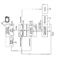
- Fig. 9 shows a block diagram of the device according to the invention according to the Fig. 8 , With the in the Fig. 2 . 5 shown device matching elements are with the same reference numerals.
- the image taken with the camera is, like the position of the camera determined by the measuring device 5 and the integrated measuring system of the robot 11, fed to the AR image generating device. Otherwise, the description of the Fig. 2 . 5 directed.
Landscapes
- Engineering & Computer Science (AREA)
- Robotics (AREA)
- Mechanical Engineering (AREA)
- Computer Vision & Pattern Recognition (AREA)
- Physics & Mathematics (AREA)
- General Physics & Mathematics (AREA)
- Theoretical Computer Science (AREA)
- Manipulator (AREA)
- Length Measuring Devices By Optical Means (AREA)
- Image Processing (AREA)
Abstract
Description
Die Erfindung betrifft ein Verfahren und eine Vorrichtung nach dem Oberbegriff des Anspruchs 1 bzw. des Anspruchs 12.The invention relates to a method and a device according to the preamble of
Die Erfindung bezieht sich insbesondere auf ein Verfahren und eine Vorrichtung zum Bestimmen der Position und der Orientierung einer Bildempfangseinrichtung, die Bilder der realen Umwelt aufnimmt, in die virtuelle Informationen, wie computergenerierte Informationen oder aber separat aufgenommene und gespeicherte Informationen mit eingeblendet werden, wie dies bei der sogenannten "erweiterten Realität" oder Augmented Reality - AR der Fall ist. Position und Orientierung werden bei Handhabungsautomaten und Robotern, die im Rahmen der Erfindung vorzugsweise solche der Norm EN ISO 8373 sind, und auch im folgenden als Pose zusammengefasst. Augmented Reality wird beispielsweise dazu eingesetzt, Arbeitskräfte bei komplizierten Montage- oder Wartungsvorgängen anzuleiten. Darüber hinaus kann Roboterprogrammierung durch Augmented Reality unterstützt werden, wie dies in der
Die kontinuierliche exakte Bestimmung der Position und Orientierung (Pose) einer entsprechenden Bildaufnahmevorrichtung ist daher im Rahmen eines Tracking erforderlich. Die Bildaufnahmeinrichtung kann dabei eine Kamera oder aber eine optische Aufnahmeinrichtung sein, wie ein halbdurchlässiger Spiegel oder die Brille eines Betrachters, in die die virtuelle Information eingeblendet wird.The continuous exact determination of the position and orientation (pose) of a corresponding image recording device is therefore necessary in the context of tracking. The image recording device can be a camera or an optical recording device, such as a semitransparent mirror or the spectacles of a viewer into which the virtual information is superimposed.
Heute werden zur Bestimmung der Pose einer Kamera häufig Marken, die von der Kamera oder einem angeschlossenen Bildbearbeitungssystem erfasst und erkannt werden können, in der realen Umgebung an räumlich genau definierten Positionen angebracht. Aus der bekannten Position wird über das Kamerabild auf die Pose der Kamera im Raum geschlossen, wie dies in der
Eine Möglichkeit ist das manuelle Teachen einer Bahn, wie es die
Wenn ein Modell einer Roboterumgebung existiert, kann in bestimmten Fällen auf das Anbringen von Marken verzichtet werden, da dann die Bestimmung des Ortes der Bildempfangseinrichtung, der Kamera, - das sogenannte Tracking - über den Vergleich von von dem Kamerabild erkannten Umgebungsmerkmalen und in einem Umgebungsmodell hinterlegten Merkmalen erfolgt. Ein derartiges Vorgehen ist einerseits bisher nicht zumindest in einer praxistauglichen Version realisiert und dürfte zum anderen keine hohen Genauigkeiten erzielen.If a model of a robot environment exists, the application of marks can be dispensed with in certain cases, since then the determination of the location of the image receiving device, the camera, the so-called tracking, via the comparison of environmental features detected by the camera image and stored in an environment model Characteristics takes place. On the one hand, such a procedure has not yet been realized, at least in a practicable version, and, on the other hand, should not achieve high accuracies.
Weiterhin ist höchst bekannt, die Bestimmung der Pose der Bildempfangseinrichtung über zusätzliche Sensorsysteme mit mechanischen, optischen, akustischen, magnetischen, trägheits- und/oder laserbasierten Sensoren vorzunehmen. Ein solches Vorgehen ist mit hohen Kosten verbunden. Darüber hinaus ist bei mechanischen Sensorsystemen, wie Fadenmesssystemen, der Aktionsbereich des Betrachters stark eingeschränkt. Bei optischen oder akustischen Systemen muss eine direkte Sichtverbindung zwischen Sender und Empfänger gegeben sein, was üblicherweise in realen Fertigungsumgebungen kaum gewährleistet ist. Darüber hinaus ist eine zeitaufwendige Kalibrierung der zusätzlichen Sensorsysteme vor Beginn der Programmierung notwendig, aber kaum praktikabel.Furthermore, it is highly known to make the determination of the pose of the image receiving device via additional sensor systems with mechanical, optical, acoustic, magnetic, inertial and / or laser-based sensors. Such a procedure is associated with high costs. In addition, in mechanical sensor systems, such as thread measuring systems, the action area of the viewer is severely limited. In optical or acoustic systems, there must be a direct line of sight between transmitter and receiver, which is usually hardly guaranteed in real production environments. In addition, a time-consuming calibration of the additional sensor systems before programming is necessary, but hardly practical.
Der Erfindung liegt daher die Aufgabe zugrunde, ein Verfahren und eine Vorrichtung zum Bestimmen der Pose (Position und Orientierung) einer Bildempfangseinrichtung zu schaffen, die bei hoher Genauigkeit der Posen-Bestimmung ohne allzu große Kosten realisierbar ist.The invention is therefore based on the object to provide a method and an apparatus for determining the pose (position and orientation) of an image receiving device, which can be realized with high accuracy of the pose determination without too great a cost.
Erfindungsgemäß wird die genannte Aufgabe mit einem Verfahren der eingangs genannten Art mit den kennzeichnenden Merkmalen des Anspruchs 1 gelöst. Eine Vorrichtung der eingangs genannten Art sieht zur Lösung der genannten Aufgabe die kennzeichnenden Merkmale des Anspruchs 12 vor.According to the invention, the object is achieved by a method of the type mentioned above with the characterizing features of
Durch die Erfindung wird ermöglicht in Echtzeit, d.h. mindestens mit der Videoaktivrate, die Pose der Kamera in Echtzeit zu ermitteln, wodurch eine einfache und kostengünstige Visualisierung von einer jeweiligen Pose der Kamera zugeordneten Informationen, insbesondere handhabungsautomatinternen Informationen ermöglicht wird.The invention enables in real time, i. at least with the video active rate, to determine the pose of the camera in real-time, thereby enabling a simple and cost-effective visualization of information associated with a particular pose of the camera, in particular automatic handling information.
Zur Erreichung des Ziels einer glaubwürdigen in Echtzeit ablaufenden Augmentierung von Steuerungsinformationen mit Hilfe eines Video See-Through AR Systems ist es notwendig, die Pose einer Kamera schnell zu bestimmen und für einen Betrachter interessante virtuelle Objekte dem eigentlich aufgenommenen Videobild zu überlagern. Das Tracking zur fortlaufenden Bestimmung der Kamerapose wird mittels Winkelenkondern und Kenntnissen über die Vorwärtskinematik desjenigen Roboters erreicht, an dem die Kamera montiert ist. Die zu überlagernden Informationen können von der Robotersteuerung des Kamera haltenden Roboters selber oder aber von anderen Rechnern, die "interessante" Informationen bereithalten könnten (z.B. von anderen Maschinen- oder Robotersteuerungen), kommen. Bei der Visualisierung von aus anderen Steuerungen kommenden Informationen ist es erforderlich, die räumliche Beziehung zwischen den Ursprungskoordinatensystemen der Steuerungen zu kennen bzw. es muss sichergestellt sein, dass alle Steuerungen ihre Informationen bezüglich eines Koordinatensystems (z.B. des Weltkoordinatensystems des Kamera führenden Roboters) bekannt geben. Zur Transformation in das Kamerakoordinatensystem des Kamera führenden Roboters muss die Beziehung zwischen Kamerakoordinatensystem und Flanschkoordinatensystem, z.B. durch Kalibrierung, bekannt sein.To achieve the goal of credible real-time augmentation of control information using a Video See-Through AR system, it is necessary to quickly determine the pose of a camera and superimpose interesting virtual objects to the viewer's actual captured video image. The tracking for the continuous determination of the camera pose is by means of angle sensors and knowledge of the forward kinematic of the robot to which the camera is mounted. The information to be superimposed may come from the robot controller of the camera-holding robot itself or from other computers that could hold "interesting" information (eg from other machine or robot controllers). When visualizing information coming from other controllers, it is necessary to know the spatial relationship between the origin coordinate systems of the controllers or to ensure that all controllers disclose their information concerning a coordinate system (eg the world coordinate system of the camera-guiding robot). To transform into the camera coordinate system of the camera leading robot, the relationship between the camera coordinate system and the flange coordinate system, eg, by calibration, must be known.
Die robotereigene, in diesen integrierte Messeinrichtung beinhaltet vorzugsweise die Winkelsensoren in den Achsantrieben eines solchen Roboters.The robot's own, in this integrated measuring device preferably includes the angle sensors in the final drives of such a robot.
In bevorzugter Ausgestaltung ist die Bildempfangseinrichtung eine Kamera, die entweder auf einem zur Ausführung einer Aufgabe programmierten Handhabungsautomaten oder Roboter angeordnet sein kann, und zwar vorzugsweise beispielsweise an dessen Handflansch oder einem mit diesem verbundenen Werkzeug oder aber auf einem zusätzlich zu dem zur Ausführung einer Aufgabe programmierten Roboter vorhandenen weiteren Roboter.In a preferred embodiment, the image receiving device is a camera, which can be arranged either on a programmed for executing a task handling machines or robots, preferably, for example, on the hand flange or a tool connected to this or on an additional programmed to perform a task Robot existing another robot.
Während die Bildempfangseinrichtung grundsätzlich ein optisches Sichtgerät sein kann, ist es bevorzugterweise eine (Video-)Kamera. Eine bevorzugte Weiterbildung sieht vor, dass virtuelle Informationen, insbesondere Handhabungsautomat, spezifische, in von der Bildempfangseinrichtung aufgenommenen Bilder zeit- und/oder lagerichtig eingeblendet werden bzw. dass durch eine Einrichtung zum zeit- und/oder lagerichtigen Einblenden virtueller Informationen, insbesondere Handhabungsautomat, spezifische, in von der Bildempfangseinrichtung aufgenommenen Bilder aufweist.While the image receiving device may basically be an optical viewing device, it is preferably a (video) camera. A preferred embodiment provides that virtual information, in particular handling machine, specific, in the images received by the image receiving device images are displayed in time and / or correct position or that by a device for time and / or positionally hiding virtual information, in particular Handling machine, specific, received in the image receiving device images.
In bevorzugter Weiterbildung der Erfindung kann vorgesehen sein, dass eine Kamera an einem Handhabungsautomaten verwendet wird, der insbesondere zur Ausführung von Aufgaben programmiert ist, dass eine Kamera auf einem einem zur Ausführung von Aufgaben programmierten Handhabungsautomaten benachbarten Handhabungsautomat verwendet wird und/oder dass die Pose einer Bildempfangseinrichtung mittels einer mit einem Handhabungsautomaten verbundenen Messeinrichtung bestimmt wird. Der in der Regel gegebene Offset zwischen Kamera und einem bekannten Ort am Handhabungsgerät, wie einem Handflansch oder TCP, kann in bekannter Weise, beispielsweise durch Vermessen oder aber in der weiter unten gegebenen Weise bestimmt werden.In a preferred embodiment of the invention can be provided that a camera is used on a handling machine that is programmed in particular for the execution of tasks that a camera is used on a programmed for execution of tasks handling machines adjacent handling machine and / or that the pose of a Image receiving device is determined by means connected to an automatic handling device measuring device. The usually given offset between the camera and a known location on the handling device, such as a hand flange or TCP, can be determined in a known manner, for example by surveying or in the manner given below.
In weiteren bevorzugten Ausgestaltungen der Erfindung ist vorgesehen, dass die Pose eines Handhabungsautomaten im Raum mittels mindestens einer im Raum angeordneten Marke sowie mindestens einer am Roboter angeordneten Messeinrichtung, wie einer Kamera oder eines Sensors bestimmt wird oder, dass die Pose eines Handhabungsautomaten im Raum mittels mindestens einer am Handhabungsautomaten angeordneten Marke sowie mindestens einer vom Handhabungsautomaten unabhängig angeordneten Messeinrichtung, wie einer Kamera oder mindestens eines Sensors bestimmt wird.In further preferred embodiments of the invention, it is provided that the pose of a handling machine in the room by means of at least one arranged in space mark and at least one arranged on the robot measuring device, such as a camera or a sensor is determined or that the pose of a handling machine in the room by means of at least a mark arranged on the automatic handling machine and at least one measuring device independently arranged by the automatic handling machine, such as a camera or at least one sensor.
Zur Kalibrierung kann die Kamera so künstliche Marken an verschiedenen Posen bildmäßig aus mehreren Positionen erfassen, wodurch ihre Positionen gegenüber den Marken und hierdurch handhabungsautomateigene Messeinrichtungen bestimmte Positionen des Roboters bzw. genauer des Flanschs oder TCP (Tool Center Point) - auch bei zunächst unbestimmten Offset zwischen Kamera und Flansch oder TCP - der Offset und letztendlich die Position im Raum bestimmt werden kann. Hierzu blickt die vom Roboter - aktiv - bewegte Kamera unter verschiedenen Winkeln auf bestimmte Marken. Aus jeder Messpose lässt sich die Position der Kamera, genauer des Kamerakoordinatensystems, im Raum bestimmen. Über die Kenntnis der Position des Roboterflansches zu diesem Zeitpunkt und die Mittelung über mehrere Messungen lässt sich so der Bezug (Offset) zwischen Kamera- und Flanschkoordinatensystem ermitteln.For calibration, the camera can thus capture artificial marks on different poses pictorially from several positions, whereby their positions relative to the marks and thereby handling automatic measuring devices specific positions of the robot or more precisely the flange or TCP (Tool Center Point) - even at first indeterminate offset between Camera and flange or TCP - the offset and finally the position in space can be determined. To do this, the robot actively moving the camera looks at certain marks at different angles. From each measurement pose, the position of the camera, or more precisely of the camera coordinate system, can be determined in space. By knowing the position of the robot flange at this time and averaging over several measurements, the reference (offset) between camera and flange coordinate system can be determined.
Gemäß einer bevorzugten Ausgestaltung der Erfindung ist vorgesehen, dass die Pose eines Handhabungsautomaten relativ zu einem anderen mittels einer auf einem Handhabungsautomaten angeordneten Marke und einer am anderen Handhabungsautomaten angeordneten Messeinrichtung, wie einer Kamera oder eines Sensors bestimmt wird. Erfindungsgemäß bilden Kamera und diese tragender Roboter mit roboterinterner Messeinrichtung sowie AR-Systemkomponenten eine Einheit. Ein zweiter Roboter kann als Teil einer Arbeitszelle betrachtet werden, dessen reale Gegebenheiten mit Informationen aus dieser Arbeitszelle augmentiert werden sollen, z.B. die am zweiten Roboter programmierte Bahn. Dazu ist es erforderlich, dass der erste Roboter weiß, wo er in Bezug zum zweiten Roboter steht. Diese Beziehung kann durch eine Kalibrierung geschehen. Nach erfolgter Kalibrierung ist es für den ersten Roboter ein leichtes, die Daten aus der Robotersteuerung des zweiten Roboters in die Bildkoordinaten seiner Kamera zu transformieren und dem aufgenommenen Bild zu augmentieren.According to a preferred embodiment of the invention, it is provided that the pose of an automatic handling device is determined relative to another by means of a mark arranged on an automatic handling machine and a measuring device arranged on the other automatic handling device, such as a camera or a sensor. According to the invention, the camera and this carrying robot with robot-internal measuring device and AR system components form a unit. A second robot may be considered part of a workcell whose realities are to be augmented with information from that workcell, e.g. the path programmed on the second robot. This requires that the first robot knows where it is in relation to the second robot. This relationship can be done by calibration. After calibration, it is easy for the first robot to transform the data from the robot control of the second robot into the image coordinates of its camera and to augment the recorded image.
Die gemäß vorstehendem zu augmentierenden Daten werden von der Steuerung des zweiten Roboters geliefert. Anstelle oder zusätzlich zu diesem zweiten Roboter könnte sich eine Werkzeugmaschine in der Arbeitszelle befinden. Auch Werkzeugmaschinen verfügen über eine Steuerung, und es sind viele Möglichkeiten vorstellbar, Steuerungsinformationen nutzbringend zu visualisieren, z.B. Koordinatensysteme der Maschinensteuerung, virtuell zu bearbeitende Objekte im Rahmen eines Testlaufs, virtuelle Werkzeuge, die realen Werkstücken im Innenraum der Werkzeugmaschine überlagert werden.The data to be augmented according to the above is supplied from the controller of the second robot. Instead of or in addition to this second robot, a machine tool could be in the workcell. Even machine tools have a controller, and there are many Possibilities imaginable visualize control information useful, eg coordinate systems of the machine control, virtual objects to be machined in a test run, virtual tools that are superimposed on real workpieces in the interior of the machine tool.
Der zweite Roboter, der die Kamera führt, kann im Allgemeinen auf einen anderen Arbeitsraum blicken, in dem viele andere Steuerungen aktiv sein können, z.B. Robotersteuerungen und andere Maschinensteuerungen, deren Informationen visualisiert werden sollen. Im Gegensatz zur Visualisierung im Rahmen von Augmented Reality von roboterinternen Informationen, werden also hier Informationen visualisiert, die von anderen Steuerungen als der eigenen Steuerung stammen. Die Steuerungen müssen dazu - echtzeitfähig - vernetzt sein, damit die Informationen schritthaltend mit den Änderungen in der Wirklichkeit eingeblendet werden können. Weiterhin ist eine Modellbildung der Arbeitszelle erforderlich, die wiederum eine Kalibrierung nach sich zieht, damit glaubwürdig augmentiert werden kann.The second robot carrying the camera may generally look at another workspace in which many other controls may be active, e.g. Robot controls and other machine controls whose information is to be visualized. In contrast to the visualization in the context of augmented reality of robot-internal information, so here information is visualized, which come from other controls than the own control. The controllers must be - real-time capable - networked so that the information can be faded in with the changes in reality. Furthermore, a modeling of the work cell is required, which in turn entails a calibration, so that credible augmented.
Die Kameraführung durch den Roboter kann aktiv oder passiv sein. Aktiv bedeutet, dass der Roboter ein Programm abfährt ("Kamerafahrt" über eine bestimmte Szene hinweg) oder über Sensorik (z.B. die angebrachte Kamera) automatisch positioniert wird. Passiv bedeutet, dass ein Bediener, der die AR-Informationen für seine Zwecke nutzen möchte, den Roboter so positioniert, dass er die gewünschten Informationen bekommt. Diese Positionierung kann durch ein Führen des Roboters erfolgen (im so genannten Manipulatorbetrieb, bei dem z.B. am Roboter ein Kraft-Momenten-Sensor angebracht ist, über den gewünschte Bewegungsrichtungen aufgeprägt werden) oder über das Bedienhandgerät (z.B. durch Drücken der Verfahrtasten oder Betätigen der 6D-Maus).Camera tracking by the robot can be active or passive. Active means that the robot moves away from a program ("camera movement" over a certain scene) or is automatically positioned via sensors (eg the attached camera). Passive means that an operator who wants to use the AR information for their own purposes positions the robot to get the information they want. This positioning can be done by guiding the robot (in the so-called manipulator mode in which, for example, a force-moment sensor is attached to the robot over which desired directions of movement are impressed) or via the hand-held device (eg by pressing the movement keys or pressing the 6D -Mouse).
Eine weitere Besonderheit der Erfindung ist, dass der Roboter eine teils aktive, teils passive Rolle einnehmen kann. Während ein Benutzer den Roboter von Hand führt oder mittels Verfahrtasten bewegt, können die Bewegungsfreiheitsgrade des Roboters beliebig eingeschränkt werden, z.B. auf einen Raum, in dem sich der Roboter mit allen sechs Freiheitsgraden bewegen kann, oder auf eine beliebige Ebene, Bahn oder auch nur einen Punkt, um den herum der TCP orientiert werden kann. So können mit Hilfe des Roboters beliebige Kamerafahrten von Hand parametriert durchgeführt werden, z.B. manuelles Führen des Roboters auf einer fest vorgegebenen Bahn durch den Raum, wobei die Orientierungsfreiheitsgrade frei gegeben sein könnten.Another special feature of the invention is that the robot can take on a partly active, partly passive role. While a user guides or moves the robot by hand, the degrees of freedom of movement of the robot can be arbitrarily restricted, e.g. to a space where the robot can move with all six degrees of freedom, or to any level, orbit, or just a point around which the TCP can be oriented. Thus, with the help of the robot, any camera movements can be performed manually parameterized, e.g. manually guiding the robot on a fixed path through the room, where the orientation degrees of freedom could be released.
Wird die Kameraführung von einem zweiten Roboter übernommen, der auf den ersten Roboter bzw. auf den vom ersten Roboter bearbeiteten Arbeitsraum blickt, so ist dies eine besondere Ausprägung der Erfindung, bei der ein Roboter eine Kamera aktiv bewegt, um virtuelle Objekte lagerichtig in das Kamerabild einblenden zu können. Die Besonderheit dabei ist, dass sich die beiden Roboter auf dasselbe Koordinatensystem beziehen und über ihre Steuerungen leicht Informationen austauschen können, die für eine Visualisierung wesentlich sind. Die Einblendung der gewünschten roboterinternen Informationen erleichtert sich dadurch. Die Roboter sind hierzu aufeinander kalibriert. Auch können die Roboter kollisionsvermeidend geführt/bewegt werden, wenn die Steuerungen miteinander verbunden sind, was mit herkömmlichen rein mechanisch arbeitenden AR-Trackingsystemen nicht möglich ist. Setzt man gar Robotersysteme mit mehr als sechs Freiheitsgraden ein, so können die redundanten Freiheitsgrade verwendet werden, um Kollisionen und Singularitäten zu umfahren (in die man beim von Hand geführten Roboter sehr leicht hineingerät) und Hindernissen auszuweichen. Die Steuerung des Kamera führenden Roboters könnte über Kollisionsvermeidungsalgorithmen verfügen, die automatisch dafür sorgen, dass der Roboter, während er von Hand geführt wird, nirgendwo kollidiert. Dies ist ein großer Vorteil gegenüber rein passiven Systemen, weil der Benutzer immer dafür sorgen muss, dass das System nicht kollidiert.If the camera guide is taken over by a second robot, which looks at the first robot or at the working space machined by the first robot, this is a special feature of the invention, in which a robot actively moves a camera to position virtual objects in the camera image in the correct position to be able to show. The peculiarity is that the two robots refer to the same coordinate system and can easily exchange information via their controls, which are essential for visualization. The insertion of the desired robot-internal information facilitates thereby. The robots are calibrated for each other. Also, the robots can be collision avoiding guided / moved when the controls are connected to each other, which is not possible with conventional purely mechanical AR tracking systems. If one uses robotic systems with more than six degrees of freedom, the redundant degrees of freedom can be used to avoid collisions and singularities (which are very easy to get into when using a hand-guided robot) and avoid obstacles. The Control of the camera-leading robot could have collision avoidance algorithms that automatically ensure that the robot does not collide while being manually guided. This is a big advantage over purely passive systems because the user always has to make sure that the system does not collide.
Die Kamera kann darüber hinaus auch an einem eine Videoanzeige aufweisenden Bediengerät, das von einem Nutzer getragen wird, angeordnet sein. Insbesondere wenn die Bildempfangseinrichtung von einem Nutzer getragen wird, kann es sich auch um ein optisches Sichtgerät, wie einen halbdurchlässigen Spiegel oder eine von einem Nutzer getragene Brille handeln, in die die virtuellen Daten oder Objekte eingeblendet werden.The camera can also be arranged on a video display having an operator unit, which is carried by a user. In particular, when the image receiving device is carried by a user, it may also be an optical viewing device, such as a semitransparent mirror or worn by a user glasses in which the virtual data or objects are superimposed.
In diesen Fällen, in denen der Nutzer die Bildempfangseinrichtung trägt, ist mit einem der vorstehenden genannten Handhabungsautomaten oder Roboter eine (weitere) Messeinrichtung verbunden, die beispielsweise eine Kamera sein kann oder aber auch optische, akustische, oder mechanische Sensoren aufweisen kann, mittels derer die genaue Lage der vom Nutzer getragenen Bildempfangseinrichtung relativ zur mit dem Roboter verbundenen Messeinrichtung bestimmt werden kann, wodurch dann wieder unter zu Hilfenahme der handhabungsautomateigenen Messeinrichtung der Ort der vom Nutzer getragenen Bildempfangseinrichtung im Raum bestimmt werden kann. Vorzugsweise ist die Bildempfangseinrichtung, wenn sie denn separat von einem der Handhabungsautomaten oder Roboter angeordnet ist, mit Marken, wie insbesondere optischen, aber auch akustischen Marken versehen, wobei dann eine entsprechende Messeinrichtung eingesetzt wird.In these cases, in which the user wears the image receiving device, one (further) measuring device is connected to one of the aforementioned handling machines or robots, which may be for example a camera or else may have optical, acoustic, or mechanical sensors, by means of which precise location of the image receiving device carried by the user relative to the measuring device connected to the robot can be determined, which then again with the help of the handling machine's own measuring device, the location of the user-supported image receiving device can be determined in space. Preferably, the image receiving device, if it is arranged separately from one of the handling machines or robots, provided with brands, such as in particular optical, but also acoustic marks, in which case a corresponding measuring device is used.
Weitere Vorteile und Merkmale der Erfindung ergeben sich aus den Ansprüchen und aus der nachfolgenden Beschreibung, in der Ausführungsbeispiele der Erfindung unter Bezugnahme auf die Zeichnung im einzelnen erläutert sind. Dabei zeigt:
- Fig. 1
- eine schematische Darstellung eines mit einer Bilderfassungseinrichtung in Form einer Kamera versehenen, Werkstücke bearbeitenden Roboters;
- Fig. 2
- ein Blockschaltbild mit den Komponenten und dem Informationsfluss bei dem Gegenstand der
Fig. 1 ; - Fig. 3
- ein Flussdiagramm zum Ändern von Verfahrbefehlen bei der Positionsbestimmung einer mit einem Roboter verbundenen Kamera;
- Fig. 4
- eine schematische Darstellung einer erfindungsgemäßen Vorrichtung mit einem zusätzlich zu einem ein Werkstück bearbeitenden Roboter vorgesehenen weiteren, mit einer Bildempfangseinrichtung versehenen benachbarten Roboter;
- Fig. 5
- ein Blockschaltbild zu den Komponenten und den Informationsfluss mit dem Gegenstand der
Fig. 4 ; - Fig. 6
- eine schematische Darstellung eines mit Referenzmarken versehenen Werkstück bearbeitenden Roboters und mit einem zusätzlichen, eine Bilderfassungseinrichtung in Form einer Kamera aufweisenden Roboter;
- Fig. 7
- eine schematische Darstellung eines mit einer Messeinrichtung versehenen Werkstück bearbeitenden Roboters sowie ortsfesten Marken;
- Fig. 8
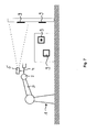
- eine schematische Darstellung einer von einem Benutzer getragenen Bildempfangseinrichtung und eines mit einer Messeinrichtung versehenen Roboters; und
- Fig. 9
- Blockdiagramm mit den Komponenten des Informationsflusses beim Gegenstand der
Fig. 8 .
- Fig. 1
- a schematic representation of provided with an image capture device in the form of a camera, processing workpieces robot;
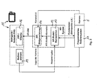
- Fig. 2
- a block diagram with the components and the flow of information in the subject of the
Fig. 1 ; - Fig. 3
- a flowchart for changing movement commands in the position determination of a camera connected to a robot;
- Fig. 4
- a schematic representation of a device according to the invention with a further provided in addition to a workpiece machining robot, provided with an image receiving device adjacent robot;
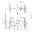
- Fig. 5
- a block diagram of the components and the flow of information with the subject of
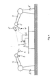
Fig. 4 ; - Fig. 6
- a schematic representation of a workpiece provided with reference marks robot and with an additional, an image capture device in the form of a camera having robot;
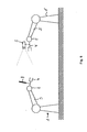
- Fig. 7
- a schematic representation of a provided with a measuring device workpiece machining robot and fixed marks;
- Fig. 8
- a schematic representation of a user-carried image receiving device and provided with a measuring robot; and
- Fig. 9
- Block diagram with the components of the flow of information in the subject matter of
Fig. 8 ,
Die
Nicht dargestellt ist ein einem Bediener oder Nutzer zugeordnetes Sichtgerät mit einer Anzeige des von der Bildempfangseinrichtung 5 aufgenommenen realen Bildes und der Einblendung eines von virtuellen Informationen, insbesondere Bildinformationen in lagerichtiger Zuordnung zum Realbild.Not shown is an operator associated with a user or user viewing device with a display of the image received by the
Zum Anzeigen von augmentierten Objekten durch lagerichtiges Einblenden auf der Anzeige muss die Position der Bilderfassungseinrichtung 5 (Kamera) im Raum bekannt sein. Diese kann bei der in der
Eine für den Gegenstand der
Die in der vorstehenden Weise gewonnene Aussage über Ort und Ausrichtung der Kamera (zusammen als "Pose" bezeichnet) wird von dem programmierten Robotersystem 11 in die Bildgenerierungskomponente 14 des AR-Systems 12 eingeseist, ebenso wie das Kamerabild von der Kamera 5 eingespeist wird. Die zu augmentierenden Objekte, wie beispielsweise Bahnpunkte der abzufahrenden Bahn oder räumliche Positionen von Koordinatensystemen, werden dem AR-System von der Robotersteuerung zur Verfügung gestellt. Das insgesamt generierte AR-Bild (mit realem Bildausschnitt und in diesen eingeblendete augmentierte Informationen) wird für den Benutzer auf dem Display 16 des Sichtgeräts 15 dargestellt. Über die Bedienelemente 17 ist eine räumliche Manipulation der augmentierten Objekte möglich, also beispielsweise ein relatives Verschieben derselben zum realen Bild. Diese Nutzereingaben werden von der AR-Modell-Manipulationskomponente 13 des AR-Systems erfasst und verarbeitet. Die durch Veränderung des augmentierten Objektes diese betreffende manipulierte Information kann bei Bedarf in die Robotersteuerung zurückgeschrieben werden.The statement about the location and orientation of the camera (referred to collectively as "pose") obtained in the above manner is input by the programmed
Um eine AR-Szene, z.B. die augmentierte Bahn des Roboter-Werkzeug-Zentrums-Punkts (Tool Center Point - TCP) gemäß der Abarbeitung eines Roboterverfahrprogramms, zu betrachten, kann der Benutzer den Roboter 1 manuell so verfahren, dass die Kamera 5 den interessierenden Bildausschnitt darstellt. Eine Kollision kann durch eine automatische Überwachung der Bahn oder aber durch den Benutzer vermieden werden.To create an AR scene, e.g. To view the augmented trajectory of the robot tool center point (TCP) in accordance with the execution of a robot traversing program, the user can manually manipulate the
Soll ein Bahnverlauf durch Änderung von Verfahrbefehlen geändert werden (Schritt A in
Der Roboter orientiert dabei die Kamera stets so, dass zur Augmentierung ausgewählte Objekt in der Mitte des Bildschirms erscheint. Der Nutzer kann gegebenenfalls die räumliche Position und Orientierung des augmentierten Objekts in bekannter Weise - beispielsweise entsprechend der
Hierzu kann wie der Betrachtungspunkt auch der Zielpunkt, wenn er nicht dem gewünschten entspricht, geändert werden (Schritt D'), indem er seitens des Benutzers manipuliert wird (Schritt E') und die geänderte Bewegungsbahn in der augmentierten Realität visualiert wird (Schritt F), wobei gegebenenfalls die Manipulation von Betrachtungspunkt und Zielpunkt wechselweise vorgenommen werden kann. Sind beide in geeigneter Weise eingestellt, so kann der Nutzer den entsprechenden Verfahrbefehl des Roboters abspeichern (Schritt E). Sollen weitere Verfahrbefehle geändert werden, so geschieht dies in der vorstehend beschriebenen Weise oder aber der entsprechende Ablauf ist geändert (Schritt A) .For this purpose, like the viewing point, the target point, if it does not correspond to the desired one, can be changed (step D ') by being manipulated by the user (step E') and the changed trajectory can be visualized in the augmented reality (step F). , where appropriate, the manipulation of the viewing point and target point can be made alternately. If both are set appropriately, the user can save the corresponding movement command of the robot (step E). If further movement commands are to be changed, this is done in the manner described above or else the corresponding sequence is changed (step A).
Durch das vorstehend beschriebene automatisch unterstützte Verfahren wird der Nutzer entlastet, da er nur drei der insgesamt sechs räumlichen Freiheitsgrade selbst steuern muss, nämlich die, die für ihn relevant sind, so das Schwenken der Kamera zum einen in zwei Richtungen sowie den Abstand vom augmentierten Objekt. Das "Zielen" auf das augmentierte Objekt übernimmt der Roboter mit seinen übrigen Freiheitsgraden selbst.The automatic assisted method described above relieves the user of having to control only three of the six spatial degrees of freedom, namely those that are relevant to him, such as pivoting the camera in two directions and the distance from the augmented object , The "targets" on the augmented object takes over the robot with its other degrees of freedom itself.
Durch das anhand des vorstehenden Ausführungsbeispiels beschriebene Vorgehen können räumliche Informationen aus der Robotersteuerung effizient visualisiert werden, wie der Bahnverlauf des Tool-Center-Punktes bei der Abarbeitung eines Roboterprogramms oder dergleichen.By the procedure described with reference to the above embodiment, spatial information from the robot controller can be efficiently visualized, such as the trajectory of the tool center point in the execution of a robot program or the like.
Während bei der Ausgestaltung der erfindungsgemäßen Vorrichtung gemäß
Die
Ansonsten stimmt das Blockdiagramm und der Informationsfluss mit dem unter Bezug auf die
Wie schon erwähnt, lässt sich durch einen zusätzlichen, eine Bilderfassungseinrichtung tragenden Roboter oder mehrere benachbarte Roboter ein deutlich besserer Blickwinkel auf die zu augmentierenden Objekte realisieren, als bei der Ausführungsform der
Sind Position und Orientierung der Roboter relativ zueinander nicht bekannt, so ist eine entsprechende Kalibrierung durchzuführen. Zur Veranschaulichung derselben sind die beiden Roboter 1 und 1' wieder in der
Bei der Ausgestaltung der
Die Art der Marken 9 kann unterschiedlich sein. Es können, wie in der
Hierzu kann nach einer Grobpositionierung des Roboters derart, dass eine Marke im Erfassungsbereich der Messeinrichtung liegt, der Roboter die Messeinrichtung systematisch durch den Raum bewegen, während die Messeinrichtung versucht, eine Marke zu erfassen. Ist eine Marke von der Messeinrichtung erfasst, wird ihre Position relativ zur Messeinrichtung bestimmt. Über die Positionsmessung der Winkelmesssysteme in den Roboterachsen und ein geeignetes Robotermodell kann die Position der Messeinrichtung relativ zu einem Bezugspunkt des Roboters, wie dem Fußpunkt des Roboters, bestimmt werden. Durch geeignete Addition der Messergebnisse lässt sich zur Position und Orientierung der Marken im Raum relativ zum Bezugspunkt des Roboters bestimmen. Ist der Aufstellort des Roboters innerhalb eines ortsfesten Koordinatensystems bekannt, kann die Lage der Marken auch relativ zu diesem ortsfesten Koordinatensystem bestimmt werden.For this purpose, after a coarse positioning of the robot such that a mark in the detection range of the measuring device The robot systematically moves the measuring device through the room while the measuring device tries to detect a mark. If a mark is detected by the measuring device, its position relative to the measuring device is determined. By measuring the position of the angle measuring systems in the robot axes and a suitable robot model, the position of the measuring device relative to a reference point of the robot, such as the base point of the robot, can be determined. By appropriate addition of the measurement results can be determined to the position and orientation of the marks in space relative to the reference point of the robot. If the location of the robot within a stationary coordinate system is known, the position of the marks can also be determined relative to this stationary coordinate system.
Die Lageerkennung kann bei einer leistungsfähigen Messeinrichtung während der automatischen Suchbewegung bzw. Positionierbewegung bestimmt werden. Alternativ kann der Roboter, nachdem er eine Marke erfasst hat, anhalten, um im ausgeschwungenen Ruhe-Zustand die relative Lagebestimmung der Marken zur Messeinrichtung vorzunehmen. Um die Lagebestimmung im Bereich höchster Genauigkeit der Messeinrichtung vorzunehmen, kann der Roboter, nachdem er eine Marke erfasst hat, durch eine bildbasierte Regelung sich der Marke so näheren, dass eine oder mehrere Messpositionen so angenommen werden, dass eine exakte Lagebestimmung erfolgen kann.The position detection can be determined with an efficient measuring device during the automatic search movement or positioning movement. Alternatively, after detecting a mark, the robot may stop to make the relative orientation of the marks to the gauge in the swung-out state. In order to make the position determination in the highest accuracy of the measuring device, the robot, after he has detected a mark, by an image-based control of the brand closer to the mark so that one or more measuring positions are adopted so that an exact position determination can take place.
Ist die Position des Roboters innerhalb des Raums unbekannt, kann die Lage der Marken relativ zueinander bestimmt werden, wenn sich der Fußpunkt des Roboters zwischen den einzelnen Messungen der verschiedenen Marken nicht ändert. Derart kann ein Roboter auf einem mobilen Wagen eingesetzt werden, der zum Zwecke der Markenvermessung im Raum arretiert wird. Ist die Reichweite des Roboters unzureichend, kann durch Verschieben des Wagens im Raum ein Überlappen des Messbereichs und damit eine Vermessung der Marken im gesamten Raum erreicht werden.If the position of the robot within the space is unknown, the position of the marks relative to each other can be determined if the base of the robot does not change between the individual measurements of the different marks. In this way, a robot can be used on a mobile car, which locks in space for the purpose of brand measurement becomes. If the range of the robot is insufficient, moving the carriage in the room can overlap the measuring range and thus measure the marks in the entire room.
In bevorzugter Ausgestaltung können verschiedene Messverfahren zur Lagebestimmung miteinander kombiniert werden. Ein Teil der Messeinrichtung kann zur Erkennung von Marken aus größerer Entfernung ausgelegt sein, wie eine Kamera mit Weitwinkelobjektiv, eine andere Messeinrichtung, z.B. ein Infrarot-basierter Entfernungsmesser, kann zur exakten Ausrichtung der Messeinrichtung vor der Marke und Vermessung derselben verwendet werden.In a preferred embodiment, different measuring methods for determining the position can be combined with one another. A part of the measuring device may be designed to detect marks from a greater distance, such as a camera with a wide-angle lens, another measuring device, e.g. An infrared-based rangefinder can be used to precisely align the measuring device with the mark and measure it.
Die
Hierdurch kann der Benutzer selbst zusammen mit dem Sichtgerät eine beliebige Position in Bezug auf die zu betrachtende Welt, insbesondere die Werkstücke, einnehmen. Zur korrekten Einblendung von AR-Informationen mussten dann allerdings die Lage des vom Benutzer gehaltenen AR-Sichtgeräts bzw. der hiermit verbundenen Kamera im Raum bekannt sein. Zur Bestimmung derselben trägt der Roboter wiederum eine Messeinrichtung, das, wie unter Bezug auf
Als Messeinrichtungen können die vorstehend unter Bezug auf
Die
- 11
- Mehrachs-Industrie-RoboterMultiaxial industrial robot
- 1'1'
- benachbarter Roboterneighboring robot
- 22
- Handbereichhand area
- 33
- Roboterarmrobot arm
- 44
- WerkzeugTool
- 55
- Bilderfassungseinrichtung, KameraImage capture device, camera
- 5'5 '
- Messeinrichtungmeasuring device
- 66
- Werkstückeworkpieces
- 77
- Roboterbahnrobot path
- 88th
- Referenzmarkenreference marks
- 99
- im Raum angeordnete MarkenMarks arranged in space
- 1111
- programmiertes Robotersystemprogrammed robot system
- 1212
- Augmented Reality-SystemAugmented reality system
- 1313
- AR-Modell-ManipulationAR model manipulation
- 1414
- AR-BildgenerierungAR image generation
- 1515
- Sichtgerätvision device
- 15a15a
- Referenzmarkereference mark
- 1616
- Displaydisplay
- 1717
- Bedienelementecontrols
Claims (22)
- Method for determining the pose as the entirety of the position and the orientation of an image reception means, wherein the pose of the image reception means is determined using at least one handling automat measurement device, characterized in that pose defining pose data of an image reception means as obtained by at least one handling automat measurement device are respectively assigned in the respective pose to the images recorded by the image reception means.
- Method according to claim 1, characterized in that the pose of the image reception means is determined by angle sensors of the axle drives of a robot.
- Method according to one of the claims above, characterized in that virtual information, in particular automat-for-handling-specific information, is overlaid on the images recorded by the image reception means.
- Method according to one of the claims above, characterized in that as image reception means an optical sight device is used.
- Method according to one of the claims 1 to 3, characterized in that as image reception means a camera is used.
- Method according to claim 5, characterized in that a camera on an automat for handling (5) is used, which is in particular programmed to perfom tasks.
- Method according to claim 5, characterized in that a camera on an automat for handling is used that is adjacent to an automat for handling (5) programmed to perform tasks.
- Method according to one of the claims 1 to 5, characterized in that the pose of an image reception means is determined by a measurement device (5') connected to an automat for handling.
- Method according to one of the claims above, characterized in that the pose of an automat for handling (1) in the space is determined by at least one marker (9) arranged in the space and at least one measurement device (5, 5') arranged on the robot, such as a camera or a sensor.
- Method according to one of the claims 1 to 8, characterized in that the pose of an automat for handling (1) in the space is determined by at least one marker (9) arranged on the automat for handling and at least one measurement device (5, 5') arranged independently of the automat for handling, such as a camera or at least one sensor.
- Method according to one of the claims above, characterized in that the pose of an automat for handling is determined relatively to another one by a marker (8) arranged on an automat for handling and a measurement device (5, 5') arranged on the other automat for handling, such as a camera or a sensor.
- Device for the determination of the pose as the entirety of position and orientation of an image reception means with an automat for handling with an integrated handling automat measurement device for the determination of the pose of the image reception means, characterized by an assigning device to assign pose data that determine the pose of an image reception means that are obtained by at least one handling automat measurement device respectively to the images which are recorded in the respective pose.
- Device according to claim 12, characterized by a device to the time-and/or pose-correctly overlay of virtual information, in particular automat-for-handling-specific information, on the images recorded by the image reception means.
- Device according to claim 12 or 13, characterized in that the handling automat measurement device features angle sensors integrated in the joints of the robot.
- Device according to one of the claims 12 to 14, characterized in that the image reception means is an optical sight device.
- Device according to one of the claims 12 to 14, characterized in that the image reception means is a camera.
- Device according to claim 15, characterized in that the camera is arranged on an automat for handling (5), which is in particular programmed to perform a task.
- Device according to claim 16, characterized in that the camera is arranged on an automat for handling adjacent to an automat for handling programmed to perform a task.
- Device according to one of the claims 12 to 18, characterized in that on an automat for handling a measurement device is arranged to determine the place and the position of an image reception means arranged separately from the automat for handling.
- Device according to one of the claims 12 to 18, characterized by fixed markers (9) in the space and a measurement device (5, 5') arranged on an automat for handling, such as a camera or a sensor, to detect the pose of an automat for handling relatively to the markers (9).
- Device according to one of the claims 12 to 18, characterized by at least one marker (9) arranged on an automat for handling (1) and at least one measurement device (5, 5') arranged independently of the automat for handling (1), such as a camera or at least one sensor, to receive the pose of the automat for handling (1) in the space.
- Device according to one of the claims 12 to 18, characterized by a marker (8) arranged on an automat for handling (1, 1') and a measurement device (5, 5') arranged on a different automat for handling (1, 1'), such as a camera or a sensor, to determine the relative position of the two automates for handling (1, 1').
Applications Claiming Priority (2)
| Application Number | Priority Date | Filing Date | Title |
|---|---|---|---|
| DE10345743 | 2003-10-01 | ||
| DE10345743A DE10345743A1 (en) | 2003-10-01 | 2003-10-01 | Method and device for determining the position and orientation of an image receiving device |
Publications (3)
| Publication Number | Publication Date |
|---|---|
| EP1521211A2 EP1521211A2 (en) | 2005-04-06 |
| EP1521211A3 EP1521211A3 (en) | 2006-03-01 |
| EP1521211B1 true EP1521211B1 (en) | 2011-06-15 |
Family
ID=34306189
Family Applications (1)
| Application Number | Title | Priority Date | Filing Date |
|---|---|---|---|
| EP04023006A Expired - Lifetime EP1521211B1 (en) | 2003-10-01 | 2004-09-28 | Method and apparatus for determining the position and orientation of an image receiving device |
Country Status (5)
| Country | Link |
|---|---|
| US (1) | US7818091B2 (en) |
| EP (1) | EP1521211B1 (en) |
| JP (1) | JP2005106825A (en) |
| AT (1) | ATE513279T1 (en) |
| DE (1) | DE10345743A1 (en) |
Cited By (2)
| Publication number | Priority date | Publication date | Assignee | Title |
|---|---|---|---|---|
| EP2728374A1 (en) | 2012-10-30 | 2014-05-07 | Technische Universität Darmstadt | Invention relating to the hand-eye calibration of cameras, in particular depth image cameras |
| RU2713570C1 (en) * | 2018-12-20 | 2020-02-05 | Анатолий Александрович Перепелица | Method for generating augmented reality image and robotic system for its implementation |
Families Citing this family (76)
| Publication number | Priority date | Publication date | Assignee | Title |
|---|---|---|---|---|
| US7065892B2 (en) * | 2001-03-19 | 2006-06-27 | Veeco Instruments Inc. | Method and apparatus for calibrating a vision system to a parts handling device |
| US8458028B2 (en) * | 2002-10-16 | 2013-06-04 | Barbaro Technologies | System and method for integrating business-related content into an electronic game |
| DE102005011616B4 (en) * | 2004-05-28 | 2014-12-04 | Volkswagen Ag | Mobile tracking unit |
| DE102005009437A1 (en) * | 2005-03-02 | 2006-09-07 | Kuka Roboter Gmbh | Method and device for fading AR objects |
| DE102005037841B4 (en) | 2005-08-04 | 2010-08-12 | Gesellschaft zur Förderung angewandter Informatik e.V. | Method and arrangement for determining the relative position of a first object with respect to a second object, and a corresponding computer program and a corresponding computer-readable storage medium |
| DE102005045854B3 (en) * | 2005-09-26 | 2007-04-12 | Siemens Ag | Method and system for calibrating a camera in production machines |
| DE102005058867B4 (en) * | 2005-12-09 | 2018-09-27 | Cine-Tv Broadcast Systems Gmbh | Method and device for moving a camera arranged on a pan and tilt head along a predetermined path of movement |
| KR20080029548A (en) * | 2006-09-29 | 2008-04-03 | 삼성전자주식회사 | System and method of moving device control based on real environment image |
| EP2048557B1 (en) | 2007-10-11 | 2013-03-27 | Sick Ag | Optoelectronic sensor and mobile device and configuration method |
| DE102007060653A1 (en) * | 2007-12-15 | 2009-06-18 | Abb Ag | Position determination of an object |
| JP4347386B2 (en) * | 2008-01-23 | 2009-10-21 | ファナック株式会社 | Processing robot program creation device |
| JP5384178B2 (en) * | 2008-04-21 | 2014-01-08 | 株式会社森精機製作所 | Machining simulation method and machining simulation apparatus |
| AT506865B1 (en) | 2008-05-20 | 2010-02-15 | Siemens Vai Metals Tech Gmbh | DEVICE FOR IMPROVING ACCURACY CHARACTERISTICS OF HANDLING DEVICES |
| DE102009029062A1 (en) * | 2008-09-05 | 2010-03-11 | Mori Seiki Co., Ltd., Yamatokoriyama-shi | Method and device for processing status monitoring |
| DE102009029061A1 (en) * | 2008-09-05 | 2010-03-11 | Mori Seiki Co., Ltd., Yamatokoriyama-shi | Method and device for processing status check |
| WO2010060475A1 (en) * | 2008-11-26 | 2010-06-03 | Abb Research Ltd. | Industrial robot |
| US8457791B2 (en) * | 2009-03-10 | 2013-06-04 | GM Global Technology Operations LLC | Method for dynamically controlling a robotic arm |
| DE102009041734B4 (en) | 2009-09-16 | 2023-11-02 | Kuka Roboter Gmbh | Measuring a manipulator |
| DE202010014359U1 (en) * | 2010-10-15 | 2012-01-17 | Hermann Eiblmeier | scanning |
| WO2012142587A1 (en) | 2011-04-15 | 2012-10-18 | Irobot Corporation | Method for path generation for an end effector of a robot |
| US8902255B2 (en) | 2011-06-18 | 2014-12-02 | Microsoft Corporation | Mobile platform for augmented reality |
| KR101978740B1 (en) | 2012-02-15 | 2019-05-15 | 삼성전자주식회사 | Tele-operation system and control method thereof |
| US9025856B2 (en) | 2012-09-05 | 2015-05-05 | Qualcomm Incorporated | Robot control information |
| JP2014069251A (en) * | 2012-09-28 | 2014-04-21 | Dainippon Screen Mfg Co Ltd | Working part control device, working robot, working part control method, and working part control program |
| US20140100694A1 (en) * | 2012-10-05 | 2014-04-10 | Beckman Coulter, Inc. | System and method for camera-based auto-alignment |
| DE102012112025B4 (en) * | 2012-12-10 | 2016-05-12 | Carl Zeiss Ag | Method and devices for determining the position of a kinematics |
| US9776325B1 (en) * | 2013-03-13 | 2017-10-03 | Hrl Laboratories, Llc | Method for tele-robotic operations over time-delayed communication links |
| US9227323B1 (en) | 2013-03-15 | 2016-01-05 | Google Inc. | Methods and systems for recognizing machine-readable information on three-dimensional objects |
| JP5742862B2 (en) * | 2013-03-18 | 2015-07-01 | 株式会社安川電機 | Robot apparatus and workpiece manufacturing method |
| US20170183157A9 (en) * | 2013-06-18 | 2017-06-29 | Hdt Robotics, Inc. | Robotic manipulator for warehouses |
| JP2015024453A (en) * | 2013-07-25 | 2015-02-05 | トヨタ自動車株式会社 | Loading determination method, loading method, loading determination device and robot |
| US9586320B2 (en) * | 2013-10-04 | 2017-03-07 | GM Global Technology Operations LLC | System and method for controlling a vision guided robot assembly |
| DE102013222456A1 (en) * | 2013-11-05 | 2015-05-07 | Kuka Laboratories Gmbh | Method for programming the motion sequences of a redundant industrial robot and associated industrial robots |
| US9283674B2 (en) * | 2014-01-07 | 2016-03-15 | Irobot Corporation | Remotely operating a mobile robot |
| US9579799B2 (en) | 2014-04-30 | 2017-02-28 | Coleman P. Parker | Robotic control system using virtual reality input |
| US9636825B2 (en) * | 2014-06-26 | 2017-05-02 | Robotex Inc. | Robotic logistics system |
| US9327406B1 (en) | 2014-08-19 | 2016-05-03 | Google Inc. | Object segmentation based on detected object-specific visual cues |
| DE102014222809B3 (en) * | 2014-11-07 | 2016-01-14 | Kuka Roboter Gmbh | Event-based redundancy angle configuration for articulated arm robots |
| US9465390B2 (en) * | 2014-11-11 | 2016-10-11 | Google Inc. | Position-controlled robotic fleet with visual handshakes |
| CN105588525B (en) * | 2014-11-14 | 2019-09-20 | 北京配天技术有限公司 | The scaling method and device of a kind of tool on robot flange coordinate system |
| JP2016221645A (en) * | 2015-06-02 | 2016-12-28 | セイコーエプソン株式会社 | Robot, robot control device and robot system |
| DE102015009151A1 (en) * | 2015-07-14 | 2017-01-19 | Kuka Roboter Gmbh | Determining an input command for a robot that is input to the robot by manually applying a force |
| US10430744B2 (en) | 2015-08-21 | 2019-10-01 | Autodesk, Inc. | Robot service platform |
| US10173324B2 (en) * | 2015-11-16 | 2019-01-08 | Abb Schweiz Ag | Facilitating robot positioning |
| JP6420229B2 (en) | 2015-12-10 | 2018-11-07 | ファナック株式会社 | A robot system including a video display device that superimposes and displays an image of a virtual object on a video of a robot |
| DE102015225844A1 (en) * | 2015-12-18 | 2017-06-22 | Robert Bosch Gmbh | Method and device for operating data glasses and data glasses |
| US20170243154A1 (en) * | 2016-02-22 | 2017-08-24 | Wal-Mart Stores, Inc. | Systems and methods for indicating worker tasks at a retail sales facility |
| JP6430986B2 (en) | 2016-03-25 | 2018-11-28 | ファナック株式会社 | Positioning device using robot |
| DE102016213663A1 (en) | 2016-07-26 | 2018-02-01 | Siemens Aktiengesellschaft | Method for controlling an end element of a machine tool and a machine tool |
| AT519176B1 (en) | 2016-10-14 | 2019-02-15 | Engel Austria Gmbh | robot system |
| DE102016224766A1 (en) * | 2016-12-13 | 2018-06-14 | Robert Bosch Gmbh | Method for calibrating sensors on a mobile platform |
| DE102016124549B4 (en) * | 2016-12-15 | 2019-11-07 | Carl Zeiss Industrielle Messtechnik Gmbh | measuring system |
| JP6527178B2 (en) * | 2017-01-12 | 2019-06-05 | ファナック株式会社 | Vision sensor calibration device, method and program |
| DE102017221305A1 (en) * | 2017-11-23 | 2019-05-23 | Robert Bosch Gmbh | Method for operating a collaborative robot |
| DE102018201589A1 (en) * | 2018-02-01 | 2019-08-01 | KORIS Vision & Force GmbH | Method for programming the control of an industrial robot, method for operating an industrial robot, programming device and industrial robot system with such a programming device |
| CN108527363A (en) * | 2018-03-08 | 2018-09-14 | 芜湖泰领信息科技有限公司 | The system of robot leaping over obstacles |
| DE102018204508A1 (en) * | 2018-03-23 | 2019-09-26 | Kuka Deutschland Gmbh | Method and system for operating a robot |
| DE102018109329B4 (en) | 2018-04-19 | 2019-12-05 | Gottfried Wilhelm Leibniz Universität Hannover | Multi-unit actuated kinematics, preferably robots, particularly preferably articulated robots |
| WO2019212985A1 (en) | 2018-04-30 | 2019-11-07 | Path Robotics, Inc. | Reflection refuting laser scanner |
| JP7034822B2 (en) * | 2018-05-01 | 2022-03-14 | 新東エスプレシジョン株式会社 | Angle measurement system |
| US10967507B2 (en) * | 2018-05-02 | 2021-04-06 | X Development Llc | Positioning a robot sensor for object classification |
| DE102018113336A1 (en) * | 2018-06-05 | 2019-12-05 | GESTALT Robotics GmbH | A method of using a machine to set an augmented reality display environment |
| JP6740288B2 (en) * | 2018-07-13 | 2020-08-12 | ファナック株式会社 | Object inspection apparatus, object inspection system, and method for adjusting inspection position |
| WO2020055903A1 (en) * | 2018-09-10 | 2020-03-19 | Fanuc America Corporation | Robot calibration for ar and digital twin |
| DE102019106458A1 (en) * | 2019-03-13 | 2020-09-17 | ese-robotics GmbH | Method for controlling an industrial robot |
| DE102019110674A1 (en) * | 2019-04-25 | 2020-10-29 | Carl Zeiss Optotechnik GmbH | Method of providing visual feedback |
| DE102019207089A1 (en) * | 2019-05-16 | 2020-11-19 | Volkswagen Aktiengesellschaft | Method and device for controlling at least one actuator system |
| US11407110B2 (en) | 2020-07-17 | 2022-08-09 | Path Robotics, Inc. | Real time feedback and dynamic adjustment for welding robots |
| DE202020106491U1 (en) | 2020-11-12 | 2022-02-16 | Sick Ag | Visualization of a protective field |
| DE102020129823B4 (en) | 2020-11-12 | 2022-07-07 | Sick Ag | Visualization of a protective field |
| CN112598752B (en) * | 2020-12-24 | 2024-02-27 | 东莞市李群自动化技术有限公司 | Calibration method and operation method based on visual recognition |
| KR20230160277A (en) | 2021-02-24 | 2023-11-23 | 패스 로보틱스, 인코포레이티드 | Autonomous welding robot |
| DE102021203779B4 (en) | 2021-04-16 | 2023-12-14 | Volkswagen Aktiengesellschaft | Method and device for annotating images of an object recorded with the aid of a camera |
| DE102022200461A1 (en) | 2022-01-17 | 2023-07-20 | Volkswagen Aktiengesellschaft | Method and robot system for machining a workpiece and coordinate system markers for a robot system |
| KR102618591B1 (en) * | 2022-11-24 | 2023-12-27 | 주식회사 버넥트 | An automated calibration system for calculating intrinsic parameter and extrinsic parameter of a camera module for precise tracking a real object, a calibration method, and a method for tracking a real object in an image based on the calibration method and augmenting a virtual model on the real object |
| KR102614102B1 (en) * | 2022-11-24 | 2023-12-14 | 주식회사 버넥트 | An automated calibration system for precise tracking a real object, a calibration method, and a method for tracking a real object in an image based on the calibration method and augmenting a virtual model on the real object |
Family Cites Families (42)
| Publication number | Priority date | Publication date | Assignee | Title |
|---|---|---|---|---|
| DE6900309U (en) | 1968-11-27 | 1969-05-22 | J E Ekornes Fabrikker As | FURNITURE MADE OF SINGLE ELEMENTS ACCORDING TO THE MODULAR PRINCIPLE |
| US3936178A (en) * | 1973-11-26 | 1976-02-03 | Coulter Information Systems, Inc. | Apparatus for large scale screen display of images |
| US4281342A (en) * | 1978-03-29 | 1981-07-28 | Hitachi, Ltd. | Mark detecting system using image pickup device |
| US4305130A (en) * | 1979-05-29 | 1981-12-08 | University Of Rhode Island | Apparatus and method to enable a robot with vision to acquire, orient and transport workpieces |
| US4402053A (en) * | 1980-09-25 | 1983-08-30 | Board Of Regents For Education For The State Of Rhode Island | Estimating workpiece pose using the feature points method |
| US4380696A (en) * | 1980-11-12 | 1983-04-19 | Unimation, Inc. | Method and apparatus for manipulator welding apparatus with vision correction for workpiece sensing |
| US5506682A (en) * | 1982-02-16 | 1996-04-09 | Sensor Adaptive Machines Inc. | Robot vision using targets |
| US4613269A (en) * | 1984-02-28 | 1986-09-23 | Object Recognition Systems, Inc. | Robotic acquisition of objects by means including histogram techniques |
| US4887223A (en) * | 1985-08-30 | 1989-12-12 | Texas Instruments Incorporated | Visual navigation system for a mobile robot having capabilities of regenerating of hidden images |
| FR2642833B1 (en) | 1989-02-06 | 1991-05-17 | Vision 3D | CALIBRATION METHOD OF A THREE-DIMENSIONAL SHAPE ACQUISITION SYSTEM AND ACQUISITION SYSTEM FOR IMPLEMENTING SAID METHOD |
| US5168528A (en) * | 1990-08-20 | 1992-12-01 | Itt Corporation | Differential electronic imaging system |
| US5268996A (en) * | 1990-12-20 | 1993-12-07 | General Electric Company | Computer image generation method for determination of total pixel illumination due to plural light sources |
| JP3173042B2 (en) * | 1991-05-21 | 2001-06-04 | ソニー株式会社 | Robot numerical controller |
| US5297238A (en) * | 1991-08-30 | 1994-03-22 | Cimetrix Incorporated | Robot end-effector terminal control frame (TCF) calibration method and device |
| US5499306A (en) * | 1993-03-08 | 1996-03-12 | Nippondenso Co., Ltd. | Position-and-attitude recognition method and apparatus by use of image pickup means |
| US5815411A (en) * | 1993-09-10 | 1998-09-29 | Criticom Corporation | Electro-optic vision system which exploits position and attitude |
| JPH06278070A (en) * | 1993-03-25 | 1994-10-04 | Nippon Steel Corp | Method for confirming object of robot work |
| DE69421873T2 (en) * | 1993-09-20 | 2000-06-15 | Canon K.K., Tokio/Tokyo | Image acquisition and display system |
| US5876325A (en) * | 1993-11-02 | 1999-03-02 | Olympus Optical Co., Ltd. | Surgical manipulation system |
| US5835693A (en) * | 1994-07-22 | 1998-11-10 | Lynch; James D. | Interactive system for simulation and display of multi-body systems in three dimensions |
| US5495410A (en) * | 1994-08-12 | 1996-02-27 | Minnesota Mining And Manufacturing Company | Lead-through robot programming system |
| GB9515311D0 (en) * | 1995-07-26 | 1995-09-20 | 3D Scanners Ltd | Stripe scanners and methods of scanning |
| US5905850A (en) * | 1996-06-28 | 1999-05-18 | Lam Research Corporation | Method and apparatus for positioning substrates |
| US6044308A (en) * | 1997-06-13 | 2000-03-28 | Huissoon; Jan Paul | Method and device for robot tool frame calibration |
| JP2001515236A (en) * | 1997-09-04 | 2001-09-18 | ダイナログ インコーポレイテッド | Method for calibrating a robot inspection system |
| US6157873A (en) * | 1998-04-09 | 2000-12-05 | Motoman, Inc. | Robot programming system and method |
| JPH11320465A (en) * | 1998-05-01 | 1999-11-24 | Murata Mach Ltd | Control method for robot arm |
| JP3343682B2 (en) * | 1999-06-18 | 2002-11-11 | 独立行政法人産業技術総合研究所 | Robot operation teaching device and operation teaching method |
| US6615112B1 (en) * | 1999-06-26 | 2003-09-02 | Kuka Schweissanlagen Gmbh | Method and device for calibrating robot measuring stations, manipulators and associated optical measuring devices |
| DE19931676C2 (en) * | 1999-07-08 | 2002-07-11 | Kuka Schweissanlagen Gmbh | Method for measuring workpieces and processing station |
| GB0008303D0 (en) * | 2000-04-06 | 2000-05-24 | British Aerospace | Measurement system and method |
| EP1356413A2 (en) * | 2000-10-05 | 2003-10-29 | Siemens Corporate Research, Inc. | Intra-operative image-guided neurosurgery with augmented reality visualization |
| JP2002172575A (en) * | 2000-12-07 | 2002-06-18 | Fanuc Ltd | Teaching device |
| DE10111130A1 (en) | 2001-03-08 | 2002-09-19 | Zeiss Carl | Coordinate measuring device with a video probe |
| US6587752B1 (en) * | 2001-12-25 | 2003-07-01 | National Institute Of Advanced Industrial Science And Technology | Robot operation teaching method and apparatus |
| CA2369845A1 (en) * | 2002-01-31 | 2003-07-31 | Braintech, Inc. | Method and apparatus for single camera 3d vision guided robotics |
| JP2005515910A (en) | 2002-01-31 | 2005-06-02 | ブレインテック カナダ インコーポレイテッド | Method and apparatus for single camera 3D vision guide robotics |
| US20030179308A1 (en) * | 2002-03-19 | 2003-09-25 | Lucia Zamorano | Augmented tracking using video, computed data and/or sensing technologies |
| JP3671219B2 (en) * | 2002-04-26 | 2005-07-13 | 独立行政法人 宇宙航空研究開発機構 | Control method for articulated robot |
| DE10305384A1 (en) | 2003-02-11 | 2004-08-26 | Kuka Roboter Gmbh | Method and device for visualizing computer-aided information |
| WO2005039836A2 (en) * | 2003-10-20 | 2005-05-06 | Isra Vision Systems Ag | Method for effecting the movement of a handling device and image processing device |
| JP2008506953A (en) * | 2004-07-14 | 2008-03-06 | ブレインテック カナダ インコーポレイテッド | Method and apparatus for machine vision |
-
2003
- 2003-10-01 DE DE10345743A patent/DE10345743A1/en not_active Withdrawn
-
2004
- 2004-09-28 AT AT04023006T patent/ATE513279T1/en active
- 2004-09-28 US US10/952,313 patent/US7818091B2/en not_active Expired - Fee Related
- 2004-09-28 EP EP04023006A patent/EP1521211B1/en not_active Expired - Lifetime
- 2004-09-30 JP JP2004286914A patent/JP2005106825A/en active Pending
Cited By (3)
| Publication number | Priority date | Publication date | Assignee | Title |
|---|---|---|---|---|
| EP2728374A1 (en) | 2012-10-30 | 2014-05-07 | Technische Universität Darmstadt | Invention relating to the hand-eye calibration of cameras, in particular depth image cameras |
| RU2713570C1 (en) * | 2018-12-20 | 2020-02-05 | Анатолий Александрович Перепелица | Method for generating augmented reality image and robotic system for its implementation |
| WO2020130882A1 (en) * | 2018-12-20 | 2020-06-25 | Владимир Яковлевич ЩЕПЕЛИН | Method and system for generating an augmented reality image |
Also Published As
| Publication number | Publication date |
|---|---|
| JP2005106825A (en) | 2005-04-21 |
| US20050131582A1 (en) | 2005-06-16 |
| ATE513279T1 (en) | 2011-07-15 |
| US7818091B2 (en) | 2010-10-19 |
| EP1521211A2 (en) | 2005-04-06 |
| DE10345743A1 (en) | 2005-05-04 |
| EP1521211A3 (en) | 2006-03-01 |
Similar Documents
| Publication | Publication Date | Title |
|---|---|---|
| EP1521211B1 (en) | Method and apparatus for determining the position and orientation of an image receiving device | |
| DE102019006800B4 (en) | Robot controller and display device using augmented reality and mixed reality | |
| DE60127644T2 (en) | Teaching device for a robot | |
| EP1447770B1 (en) | Method and apparatus for visualization of computer-based information | |
| DE102019002898B4 (en) | robot simulation device | |
| DE102018009023B4 (en) | Teaching device for carrying out robot teaching processes and teaching methods | |
| DE102017128543B4 (en) | NOISE ZONE ADJUSTMENT DEVICE FOR A MOBILE ROBOT | |
| DE102007033486B4 (en) | Method and system for mixing a virtual data model with an image generated by a camera or a presentation device | |
| DE102005060967B4 (en) | Method and device for setting up a trajectory of a robot device | |
| DE102015000587B4 (en) | A robot programming device for creating a robot program for taking an image of a workpiece | |
| EP1604789A2 (en) | Method and device for improving the positioning accuracy of a manipulator | |
| DE102018112403B4 (en) | ROBOTIC SYSTEM DISPLAYING INFORMATION FOR ASSISTING AN ROBOT | |
| DE102009012590A1 (en) | Device for determining the position of a robot arm with camera for taking pictures | |
| DE102017001131B4 (en) | Method and system for operating a robot | |
| DE10235905A1 (en) | Method of determining spatial position of an object and a workpiece for automatically mounting the workpiece on the object, involves robot holding the workpiece over object and cameras establishing coordinates of reference object | |
| DE102014017307B4 (en) | Method and system for processing a component with a robot-guided tool | |
| EP3324362A1 (en) | Method and device for commissioning multi-axis system | |
| DE102017010718A1 (en) | Method and means for operating a robot arrangement | |
| EP1172183A2 (en) | Device and arrangement for generating corrected motion data for predefined motion of a mobile installation, mobile installation and system comprising mobile installations | |
| EP1468792A2 (en) | Method for robot calibration | |
| EP1915239B1 (en) | Method for generating an environmental image | |
| DE102022202563B3 (en) | Planning a trajectory of a robot | |
| DE102005040714B4 (en) | Method and system for creating a movement sequence for a robot | |
| WO2017207364A1 (en) | Device for measuring objects | |
| DE10327479A1 (en) | Device for determining the position of a workpiece and method therefor using at least one electronic camera |
Legal Events
| Date | Code | Title | Description |
|---|---|---|---|
| PUAI | Public reference made under article 153(3) epc to a published international application that has entered the european phase |
Free format text: ORIGINAL CODE: 0009012 |
|
| AK | Designated contracting states |
Kind code of ref document: A2 Designated state(s): AT BE BG CH CY CZ DE DK EE ES FI FR GB GR HU IE IT LI LU MC NL PL PT RO SE SI SK TR |
|
| AX | Request for extension of the european patent |
Extension state: AL HR LT LV MK |
|
| PUAL | Search report despatched |
Free format text: ORIGINAL CODE: 0009013 |
|
| AK | Designated contracting states |
Kind code of ref document: A3 Designated state(s): AT BE BG CH CY CZ DE DK EE ES FI FR GB GR HU IE IT LI LU MC NL PL PT RO SE SI SK TR |
|
| AX | Request for extension of the european patent |
Extension state: AL HR LT LV MK |
|
| AKX | Designation fees paid | ||
| 17P | Request for examination filed |
Effective date: 20060817 |
|
| RBV | Designated contracting states (corrected) |
Designated state(s): AT BE BG CH CY CZ DE DK EE ES FI FR GB GR HU IE IT LI LU MC NL PL PT RO SE SI SK TR |
|
| 17Q | First examination report despatched |
Effective date: 20091119 |
|
| GRAP | Despatch of communication of intention to grant a patent |
Free format text: ORIGINAL CODE: EPIDOSNIGR1 |
|
| RIN1 | Information on inventor provided before grant (corrected) |
Inventor name: KAZI, ARIF Inventor name: BISCHOFF, RAINER |
|
| RAP1 | Party data changed (applicant data changed or rights of an application transferred) |
Owner name: KUKA LABORATORIES GMBH |
|
| GRAS | Grant fee paid |
Free format text: ORIGINAL CODE: EPIDOSNIGR3 |
|
| GRAA | (expected) grant |
Free format text: ORIGINAL CODE: 0009210 |
|
| REG | Reference to a national code |
Ref country code: DE Ref legal event code: R081 Ref document number: 502004012594 Country of ref document: DE Owner name: KUKA ROBOTER GMBH, DE Free format text: FORMER OWNER: KUKA ROBOTER GMBH, 86165 AUGSBURG, DE |
|
| AK | Designated contracting states |
Kind code of ref document: B1 Designated state(s): AT BE BG CH CY CZ DE DK EE ES FI FR GB GR HU IE IT LI LU MC NL PL PT RO SE SI SK TR |
|
| REG | Reference to a national code |
Ref country code: GB Ref legal event code: FG4D Free format text: NOT ENGLISH Ref country code: CH Ref legal event code: EP |
|
| REG | Reference to a national code |
Ref country code: IE Ref legal event code: FG4D Free format text: LANGUAGE OF EP DOCUMENT: GERMAN |
|
| REG | Reference to a national code |
Ref country code: DE Ref legal event code: R096 Ref document number: 502004012594 Country of ref document: DE Effective date: 20110721 |
|
| REG | Reference to a national code |
Ref country code: NL Ref legal event code: VDEP Effective date: 20110615 |
|
| PG25 | Lapsed in a contracting state [announced via postgrant information from national office to epo] |
Ref country code: SE Free format text: LAPSE BECAUSE OF FAILURE TO SUBMIT A TRANSLATION OF THE DESCRIPTION OR TO PAY THE FEE WITHIN THE PRESCRIBED TIME-LIMIT Effective date: 20110615 |
|
| PG25 | Lapsed in a contracting state [announced via postgrant information from national office to epo] |
Ref country code: GR Free format text: LAPSE BECAUSE OF FAILURE TO SUBMIT A TRANSLATION OF THE DESCRIPTION OR TO PAY THE FEE WITHIN THE PRESCRIBED TIME-LIMIT Effective date: 20110916 Ref country code: CY Free format text: LAPSE BECAUSE OF FAILURE TO SUBMIT A TRANSLATION OF THE DESCRIPTION OR TO PAY THE FEE WITHIN THE PRESCRIBED TIME-LIMIT Effective date: 20110615 Ref country code: SI Free format text: LAPSE BECAUSE OF FAILURE TO SUBMIT A TRANSLATION OF THE DESCRIPTION OR TO PAY THE FEE WITHIN THE PRESCRIBED TIME-LIMIT Effective date: 20110615 Ref country code: FI Free format text: LAPSE BECAUSE OF FAILURE TO SUBMIT A TRANSLATION OF THE DESCRIPTION OR TO PAY THE FEE WITHIN THE PRESCRIBED TIME-LIMIT Effective date: 20110615 |
|
| PG25 | Lapsed in a contracting state [announced via postgrant information from national office to epo] |
Ref country code: NL Free format text: LAPSE BECAUSE OF FAILURE TO SUBMIT A TRANSLATION OF THE DESCRIPTION OR TO PAY THE FEE WITHIN THE PRESCRIBED TIME-LIMIT Effective date: 20110615 |
|
| REG | Reference to a national code |
Ref country code: IE Ref legal event code: FD4D |
|
| PG25 | Lapsed in a contracting state [announced via postgrant information from national office to epo] |
Ref country code: IE Free format text: LAPSE BECAUSE OF FAILURE TO SUBMIT A TRANSLATION OF THE DESCRIPTION OR TO PAY THE FEE WITHIN THE PRESCRIBED TIME-LIMIT Effective date: 20110615 Ref country code: PT Free format text: LAPSE BECAUSE OF FAILURE TO SUBMIT A TRANSLATION OF THE DESCRIPTION OR TO PAY THE FEE WITHIN THE PRESCRIBED TIME-LIMIT Effective date: 20111017 Ref country code: EE Free format text: LAPSE BECAUSE OF FAILURE TO SUBMIT A TRANSLATION OF THE DESCRIPTION OR TO PAY THE FEE WITHIN THE PRESCRIBED TIME-LIMIT Effective date: 20110615 Ref country code: CZ Free format text: LAPSE BECAUSE OF FAILURE TO SUBMIT A TRANSLATION OF THE DESCRIPTION OR TO PAY THE FEE WITHIN THE PRESCRIBED TIME-LIMIT Effective date: 20110615 |
|
| PG25 | Lapsed in a contracting state [announced via postgrant information from national office to epo] |
Ref country code: PL Free format text: LAPSE BECAUSE OF FAILURE TO SUBMIT A TRANSLATION OF THE DESCRIPTION OR TO PAY THE FEE WITHIN THE PRESCRIBED TIME-LIMIT Effective date: 20110615 Ref country code: SK Free format text: LAPSE BECAUSE OF FAILURE TO SUBMIT A TRANSLATION OF THE DESCRIPTION OR TO PAY THE FEE WITHIN THE PRESCRIBED TIME-LIMIT Effective date: 20110615 Ref country code: RO Free format text: LAPSE BECAUSE OF FAILURE TO SUBMIT A TRANSLATION OF THE DESCRIPTION OR TO PAY THE FEE WITHIN THE PRESCRIBED TIME-LIMIT Effective date: 20110615 |
|
| BERE | Be: lapsed |
Owner name: KUKA LABORATORIES G.M.B.H. Effective date: 20110930 |
|
| PLBE | No opposition filed within time limit |
Free format text: ORIGINAL CODE: 0009261 |
|
| STAA | Information on the status of an ep patent application or granted ep patent |
Free format text: STATUS: NO OPPOSITION FILED WITHIN TIME LIMIT |
|
| PG25 | Lapsed in a contracting state [announced via postgrant information from national office to epo] |
Ref country code: MC Free format text: LAPSE BECAUSE OF NON-PAYMENT OF DUE FEES Effective date: 20110930 |
|
| REG | Reference to a national code |
Ref country code: CH Ref legal event code: PL |
|
| 26N | No opposition filed |
Effective date: 20120316 |
|
| GBPC | Gb: european patent ceased through non-payment of renewal fee |
Effective date: 20110928 |
|
| PG25 | Lapsed in a contracting state [announced via postgrant information from national office to epo] |
Ref country code: IT Free format text: LAPSE BECAUSE OF FAILURE TO SUBMIT A TRANSLATION OF THE DESCRIPTION OR TO PAY THE FEE WITHIN THE PRESCRIBED TIME-LIMIT Effective date: 20110615 |
|
| PG25 | Lapsed in a contracting state [announced via postgrant information from national office to epo] |
Ref country code: BE Free format text: LAPSE BECAUSE OF NON-PAYMENT OF DUE FEES Effective date: 20110930 Ref country code: DK Free format text: LAPSE BECAUSE OF FAILURE TO SUBMIT A TRANSLATION OF THE DESCRIPTION OR TO PAY THE FEE WITHIN THE PRESCRIBED TIME-LIMIT Effective date: 20110615 |
|
| REG | Reference to a national code |
Ref country code: DE Ref legal event code: R097 Ref document number: 502004012594 Country of ref document: DE Effective date: 20120316 |
|
| PG25 | Lapsed in a contracting state [announced via postgrant information from national office to epo] |
Ref country code: CH Free format text: LAPSE BECAUSE OF NON-PAYMENT OF DUE FEES Effective date: 20110930 Ref country code: LI Free format text: LAPSE BECAUSE OF NON-PAYMENT OF DUE FEES Effective date: 20110930 |
|
| PG25 | Lapsed in a contracting state [announced via postgrant information from national office to epo] |
Ref country code: GB Free format text: LAPSE BECAUSE OF NON-PAYMENT OF DUE FEES Effective date: 20110928 |
|
| REG | Reference to a national code |
Ref country code: AT Ref legal event code: MM01 Ref document number: 513279 Country of ref document: AT Kind code of ref document: T Effective date: 20110928 |
|
| PG25 | Lapsed in a contracting state [announced via postgrant information from national office to epo] |
Ref country code: AT Free format text: LAPSE BECAUSE OF NON-PAYMENT OF DUE FEES Effective date: 20110928 |
|
| PG25 | Lapsed in a contracting state [announced via postgrant information from national office to epo] |
Ref country code: ES Free format text: LAPSE BECAUSE OF FAILURE TO SUBMIT A TRANSLATION OF THE DESCRIPTION OR TO PAY THE FEE WITHIN THE PRESCRIBED TIME-LIMIT Effective date: 20110926 |
|
| PG25 | Lapsed in a contracting state [announced via postgrant information from national office to epo] |
Ref country code: LU Free format text: LAPSE BECAUSE OF NON-PAYMENT OF DUE FEES Effective date: 20110928 |
|
| PG25 | Lapsed in a contracting state [announced via postgrant information from national office to epo] |
Ref country code: BG Free format text: LAPSE BECAUSE OF FAILURE TO SUBMIT A TRANSLATION OF THE DESCRIPTION OR TO PAY THE FEE WITHIN THE PRESCRIBED TIME-LIMIT Effective date: 20110915 |
|
| PG25 | Lapsed in a contracting state [announced via postgrant information from national office to epo] |
Ref country code: TR Free format text: LAPSE BECAUSE OF FAILURE TO SUBMIT A TRANSLATION OF THE DESCRIPTION OR TO PAY THE FEE WITHIN THE PRESCRIBED TIME-LIMIT Effective date: 20110615 |
|
| PG25 | Lapsed in a contracting state [announced via postgrant information from national office to epo] |
Ref country code: HU Free format text: LAPSE BECAUSE OF FAILURE TO SUBMIT A TRANSLATION OF THE DESCRIPTION OR TO PAY THE FEE WITHIN THE PRESCRIBED TIME-LIMIT Effective date: 20110615 |
|
| REG | Reference to a national code |
Ref country code: DE Ref legal event code: R082 Ref document number: 502004012594 Country of ref document: DE Representative=s name: WALLINGER RICKER SCHLOTTER TOSTMANN PATENT- UN, DE Ref country code: DE Ref legal event code: R081 Ref document number: 502004012594 Country of ref document: DE Owner name: KUKA ROBOTER GMBH, DE Free format text: FORMER OWNER: KUKA LABORATORIES GMBH, 86165 AUGSBURG, DE |
|
| REG | Reference to a national code |
Ref country code: FR Ref legal event code: PLFP Year of fee payment: 13 |
|
| REG | Reference to a national code |
Ref country code: FR Ref legal event code: PLFP Year of fee payment: 14 |
|
| REG | Reference to a national code |
Ref country code: FR Ref legal event code: PLFP Year of fee payment: 15 |
|
| REG | Reference to a national code |
Ref country code: DE Ref legal event code: R082 Ref document number: 502004012594 Country of ref document: DE Representative=s name: WALLINGER RICKER SCHLOTTER TOSTMANN PATENT- UN, DE Ref country code: DE Ref legal event code: R081 Ref document number: 502004012594 Country of ref document: DE Owner name: KUKA DEUTSCHLAND GMBH, DE Free format text: FORMER OWNER: KUKA ROBOTER GMBH, 86165 AUGSBURG, DE |
|
| PGFP | Annual fee paid to national office [announced via postgrant information from national office to epo] |
Ref country code: DE Payment date: 20190917 Year of fee payment: 16 Ref country code: FR Payment date: 20190815 Year of fee payment: 16 |
|
| REG | Reference to a national code |
Ref country code: DE Ref legal event code: R119 Ref document number: 502004012594 Country of ref document: DE |
|
| PG25 | Lapsed in a contracting state [announced via postgrant information from national office to epo] |
Ref country code: FR Free format text: LAPSE BECAUSE OF NON-PAYMENT OF DUE FEES Effective date: 20200930 Ref country code: DE Free format text: LAPSE BECAUSE OF NON-PAYMENT OF DUE FEES Effective date: 20210401 |