EP3323317A1 - A showcase, especially for stores - Google Patents
A showcase, especially for stores Download PDFInfo
- Publication number
- EP3323317A1 EP3323317A1 EP17194739.3A EP17194739A EP3323317A1 EP 3323317 A1 EP3323317 A1 EP 3323317A1 EP 17194739 A EP17194739 A EP 17194739A EP 3323317 A1 EP3323317 A1 EP 3323317A1
- Authority
- EP
- European Patent Office
- Prior art keywords
- rear wall
- legs
- post
- showcase
- showcase according
- Prior art date
- Legal status (The legal status is an assumption and is not a legal conclusion. Google has not performed a legal analysis and makes no representation as to the accuracy of the status listed.)
- Granted
Links
Images



Classifications
-
- A—HUMAN NECESSITIES
- A47—FURNITURE; DOMESTIC ARTICLES OR APPLIANCES; COFFEE MILLS; SPICE MILLS; SUCTION CLEANERS IN GENERAL
- A47B—TABLES; DESKS; OFFICE FURNITURE; CABINETS; DRAWERS; GENERAL DETAILS OF FURNITURE
- A47B96/00—Details of cabinets, racks or shelf units not covered by a single one of groups A47B43/00 - A47B95/00; General details of furniture
- A47B96/14—Bars, uprights, struts, or like supports, for cabinets, brackets, or the like
- A47B96/1416—Uprights receiving panels and brackets
-
- A—HUMAN NECESSITIES
- A47—FURNITURE; DOMESTIC ARTICLES OR APPLIANCES; COFFEE MILLS; SPICE MILLS; SUCTION CLEANERS IN GENERAL
- A47F—SPECIAL FURNITURE, FITTINGS, OR ACCESSORIES FOR SHOPS, STOREHOUSES, BARS, RESTAURANTS OR THE LIKE; PAYING COUNTERS
- A47F5/00—Show stands, hangers, or shelves characterised by their constructional features
- A47F5/10—Adjustable or foldable or dismountable display stands
-
- A—HUMAN NECESSITIES
- A47—FURNITURE; DOMESTIC ARTICLES OR APPLIANCES; COFFEE MILLS; SPICE MILLS; SUCTION CLEANERS IN GENERAL
- A47B—TABLES; DESKS; OFFICE FURNITURE; CABINETS; DRAWERS; GENERAL DETAILS OF FURNITURE
- A47B2200/00—General construction of tables or desks
- A47B2200/0066—Workstations
- A47B2200/0077—Tables or desks with drawers supporting portable computers
Definitions
- the object of the invention is a showcase, especially for stores, intended to be used, among other things, on exhibition stands, at shops, markets, showrooms or warehouses.
- Such showcases often include two independent post-like legs, between which a rear wall is provided that connects the post-like legs and reinforces the whole construction.
- This set creates a showcase module and allows for extending the showcase to a desired size by combining modules in order to build a showcase of the required dimensional parameters.
- a further module is added to already assembled showcase modules in such a way that a rear wall is added to an outer post-like leg of the set and another post-like leg is installed at the other side.
- the post-like legs in addition to suitable mounting holes in the front and rear walls, have further mounting holes in the left and right walls so that all the walls of the post-like legs may have appropriate mounting holes for installation of different components.
- This type of showcases is made of metal, typically of sheets of steel or aluminium, this regards both the post-like legs and the rear walls or shelves.
- the rear wall is often equipped with hook detents on its side edges used to mount the rear wall in the mounting holes of the side walls of the post-like leg of the showcase.
- the structure of the rear wall is important for its construction.
- the rear wall is made of a flat metal sheet mounted, using the above-mentioned means, to the post-like legs.
- undesirable vibrations and reduced stability of the showcase may often be present.
- such a wall must be made of sheets of a considerable thickness, and this increases both the cost and weight of the showcase.
- the latter may be made with corrugated impressions, which increase the rigidity and allow for reducing the thickness of the sheets the rear wall is made of. Impressions may form portions of the front surface and, parallel to it, rear surface, connected by means of skew sections; however, the front and rear surfaces are separated from each other by a specified distance.
- the rear wall can be made of segments dividing the rear wall into smaller parts. Most frequently, such division is made at the rear wall, which is to say that the rear wall is formed by arranging the segments one above the other.
- French patent application FR 2799941 discloses a showcase solution with two post-like legs, to which a rear wall is attached.
- the rear wall is made of a metal sheet mounted to the post-like legs with mounting holes, provided on their side edges, which receive hook detents of a plate fixed permanently to the post-like leg.
- the rear wall is made with corrugated impressions to increase rigidity and allow for reducing the thickness of the sheets the rear wall is made of. Impressions form portions of the front surface and rear surface, parallel to it, connected by means of skew surfaces; however, the front and rear surfaces are separated from each other by a specified distance.
- Patent application EP 2695543 discloses a showcase solution with two post-like legs, to which a rear wall is attached.
- the rear wall is made of a metal sheet mounted to the post-like legs using an intermediate element.
- the rear wall is made with corrugated impressions to increase rigidity and allow for reducing the thickness of the sheets the rear wall is made of. Impressions form portions of the front surface and rear surface, parallel to it, connected by means of skew surfaces; however, the front and rear surfaces are separated from each other by a specified distance. Portions of the front surface and rear wall rear surface parallel to it, on both of its edges, are provided with rectangular mounting holes.
- An intermediate element is located between the rear wall and the post-like leg and contains at least one link adapted to secure the rear wall using its mounting hole.
- the intermediate element contains at least one mounting member, adapted for mounting in at least one complementary mounting member on the post-like leg and which contains at least one locking element, arranged for cooperation with the complementary locking element on the post-like leg.
- the post-like legs have one vertical row of holes in their side walls.
- Polish patent application P. 410953 discloses a showcase, especially for stores, containing a module with two post-like legs of a rectangular cross-section and a rear wall removably attached to the legs using a profiled connector, where the back wall is made of a metal sheet with impressions; the impressions forming parallel portions of the front surface and portions of the rear surface connected by means of skew sections.
- the rear wall at the front surface and rear surface near its side edge, is provided with shaped cut-outs formed as a hole that opens to the external side part of the rear wall, the hole having a vertical projection with a horizontal bend provided along the side part of the rear wall, wherein the holes receive a link formed as a spatially shaped element, passing through at least two adjacent holes, wherein the link contains two parallel connecting walls connected by means of platforms having, in their centre portions, vertical tabs pointed upwards of a width smaller than the distance of the connecting walls of the link, and the link has, from the external side in relation to the rear wall, shaped detents on each connecting wall, and the vertical distance between the platforms corresponds to the vertical distance of the holes in the rear wall, wherein the post-like legs, at their side walls facing the side wall, have recesses, formed as vertical slots, formed in two parallel vertical rows, by which the shaped link detents are fixed.
- U.S. patent application US 4949487 discloses modular lighting of suspended information letters, wherein electrical energy supply for this lighting is provided by a suspended horizontal strip of two current bars located in it.
- the purpose of the invention is to eliminate the defects of the prior art, provide a new range of showcases, with consideration of their lighting, and to facilitate their implementation, storage and assembly.
- the showcase especially for stores, contains a module with two post-like legs of a rectangular cross-section and a rear wall removably attached to the legs using a shaped connector, wherein the rear wall is made of a metal sheet with impressions, wherein the impressions form mutually parallel portions of the front surface and portions of the rear surface connected by means of skew sections, and the rear wall at the connection site between the components of the front surface and skew sections in the vicinity of its side edge is provided with horizontal slots in which is a link is seated formed as a flat element, passing through at least two adjacent horizontal slots and having, at the exterior side in relation to the rear wall, shaped detents to connect with post-like legs.
- horizontal slots At least at one side of the rear wall, horizontal slots, along a part of their length, at the side opposite to the legs, have a channel which receives a power strip by means of which electric power is supplied.
- the rear wall at the side opposite to the side near which, on its side part, it is equipped with horizontal slots, on vertical portions of the front surface and on vertical portions of rear surface, has shaped detents formed as hooks connectable to the recesses of the post-like legs.
- the channel is wider than the slot.
- the dimensions of the channel are equal to the transverse dimensions of the power strip.
- the power strip is a plastic profile of a shape similar to a shape of a C-profile and it is equipped with two current bars embedded in recesses in the C-profile arms, wherein the current bars cooperate with a current trolley.
- the current trolley has a rotating flattened handle transiting into the side arms with contacts coupled with the current bars of the power strip at any location, and the contacts are fitted with electrical wires supplying electrical energy to a receiver.
- the post-like legs in their front walls, are equipped with mounting holes.
- the showcase is formed of at least two modules set next to each other, wherein the adjacent modules have a common post-like leg.
- the rear wall is formed of panels arranged one above the other in an overlaying arrangement.
- the post-like legs are fitted at the bottom with extension arms and a bottom shelf extending between the extension arms.
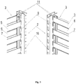
- fig. 1 is a perspective exploded view of the essential elements of the basic showcase
- fig. 2 is a perspective view of a portion of a rear wall connected using a link with a post-like leg
- fig. 3 is a perspective view of a portion of the rear wall connected using a link with a post-like leg with a power strip installed therein
- fig. 4 is another view of a portion of the rear wall connected using a link with a post-like leg with a power strip installed therein
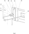
- fig. 5 is a view of a portion of the rear wall with a power strip and a current trolley before connection to the power strip
- fig. 6 is a view of a portion of the rear wall with a power strip and a current trolley after connection to the power strip.
- a module 1 of a showcase especially for stores, contains two post-like legs 2, a rear wall 3 and a link 9 enabling connection of the rear wall 3 with the post-like legs 2.
- the module 1 is additionally equipped with an extension arm 23, on which a bottom shelf 24 may be installed.
- the post-like legs 2 are made of steel sheet, though in other embodiments, they may be formed of different materials, such as an aluminium sheet.
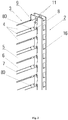
- the post-like legs 2 In the cross-section, as shown in fig. 2 , fig. 3 , and fig. 4 , the post-like legs 2 have a rectangular shape.
- Their front and rear walls are provided with mounting holes 16 which receive shelves or shelf brackets (not shown), which may be horizontal or, for better exposure of goods, tilted at a small angle.
- Both side walls of the post-like legs 2, facing the rear wall are equipped with two rows of recesses 11 formed as vertical slots used to mount the rear wall 3.
- the rear wall 3 is made, in this embodiment of the invention, of panels 15 which, in order to form the rear wall 3, are arranged one above the other. In other embodiments of the invention, these panels 15 may overlap with the upper and lower edges.
- the rear wall 3 is made of a metal plate with regular impressions 4 formed as corrugations, wherein the impressions 4 form parallel portions of the front surface 5 and portions of the rear surface 6 connected by means of skew sections 7. It is clear that, in other embodiments according to the invention, the rear wall 3 does not have to comprise corrugations across its whole surface.
- the metal plate of the rear wall 3, made of a steel sheet can be divided into panels 15 arranged one above the other. Such embodiment of the rear wall 3 contributes to simplification of the production process of the elements, as well as to improving storage and transport of such elements.
- the rear wall 3, at the front surface 5 and at the rear surface 6, near its side edge, is equipped with channels 80 transiting into horizontal slots 8.
- a link 9 is installed in the horizontal slots 8, formed as a spatially shaped element, the link 9 passing through at least two adjacent channels 80 and shifted towards the horizontal slots 8.
- a link 9, formed as a flat element, passing through at least two adjacent horizontal slots 8, has shaped detents 10 at the side external in relation to the rear wall 3.
- the shaped detents 10 are used to fix the rear wall 3 to the post-like legs 2. In order to do so, the shaped detents 10 are installed, during the showcase assembly, in the recesses 11 , provided in the post-like legs at their side walls facing the rear wall 3.
- the link 9 is equipped with shaped detents 10.
- the shaped detents 10 of the links 9 are used to connect the link 9 in the recesses 11 made in the side walls of the post-like legs 2, during the showcase assembly.
- a channel 80 is wider than a slot 8 and it corresponds to the width of a power strip 13 so that the dimensions of the channel 80 are equal to the transverse dimensions of the power strip 13.
- the width of the slot 8 corresponds to the thickness of a link 9 being a substantially flat element. In other embodiments of the invention, the width of the channel can be equal to the width of the slot 8.
- the power strip 13 is a plastic profile similar in shape to a C-profile, as shown in fig. 3 , fig. 4 , fig. 5 and fig. 6 .
- the power strip 13 is equipped with two current bars 14 passing into cavities formed in the C-profile arms of the power strip 13 profile.
- a current trolley 17 cooperates with these current bars 14 positioned in the power strip 13 profile.
- the current trolley 17 has a rotating flattened handle 18 transiting into side arms 19 with contacts 20 coupled with the current bars 14 of the power strip 13 at any location thereof, and the contacts 20 are fitted with electrical wires 21 supplying electrical energy to a receiver 22.
- the receiver 22 is positioned under a showcase shelf and it is constituted by a source of light to illuminate a space between the shelves.
- the post-like legs 2, in their front walls, are equipped with mounting holes 16, which receive the showcase elements, especially shelves.
- the post-like legs 2 are fitted at their bottom part with extension arms 23 and with a bottom shelf 24 extending between the extension arms 23.
- the rear wall 3, on a side edge, at a side opposite to the side with holes 8, on portions of a front surface 5 and portions of a rear surface 6, is equipped with shaped holders 12 formed as hooks fixable in recesses 11 of post-like legs 2 during a showcase assembly.
- both sides of a rear wall 3, near their side edges, have holes 8, in which links 9 are installed with shaped detents 15 used to fix the links 9 to post-like legs 2 during assembly of a showcase.
Landscapes
- Freezers Or Refrigerated Showcases (AREA)
- Display Racks (AREA)
Abstract
Description
- The object of the invention is a showcase, especially for stores, intended to be used, among other things, on exhibition stands, at shops, markets, showrooms or warehouses.
- Within the field of showcases used for presentation or storage of products or other items, especially on large areas, such solutions of showcases are known which include posts of various cross-sections as the basic elements, most frequently of rectangular cross-sections, provided with suitable holes mating with elements used to fix bracket arms to support shelves usually positioned in a horizontal plane or slightly inclined forwards or rearwards or to the sides for better presentation of products or items positioned on them.
- Such showcases often include two independent post-like legs, between which a rear wall is provided that connects the post-like legs and reinforces the whole construction. This set creates a showcase module and allows for extending the showcase to a desired size by combining modules in order to build a showcase of the required dimensional parameters. A further module is added to already assembled showcase modules in such a way that a rear wall is added to an outer post-like leg of the set and another post-like leg is installed at the other side. This is possible because the post-like legs, in addition to suitable mounting holes in the front and rear walls, have further mounting holes in the left and right walls so that all the walls of the post-like legs may have appropriate mounting holes for installation of different components.
- This type of showcases is made of metal, typically of sheets of steel or aluminium, this regards both the post-like legs and the rear walls or shelves. The rear wall is often equipped with hook detents on its side edges used to mount the rear wall in the mounting holes of the side walls of the post-like leg of the showcase. The structure of the rear wall is important for its construction.
- Often, the rear wall is made of a flat metal sheet mounted, using the above-mentioned means, to the post-like legs. In such solutions, undesirable vibrations and reduced stability of the showcase may often be present. To ensure appropriate parameters, such a wall must be made of sheets of a considerable thickness, and this increases both the cost and weight of the showcase.
- To increase the rigidity of the rear wall, the latter may be made with corrugated impressions, which increase the rigidity and allow for reducing the thickness of the sheets the rear wall is made of. Impressions may form portions of the front surface and, parallel to it, rear surface, connected by means of skew sections; however, the front and rear surfaces are separated from each other by a specified distance.
- To facilitate the manufacture and storage of the showcase elements when the showcase is not used, the rear wall can be made of segments dividing the rear wall into smaller parts. Most frequently, such division is made at the rear wall, which is to say that the rear wall is formed by arranging the segments one above the other.
- International patent application
WO2010031746 discloses a showcase with two post-like legs, to which a rear wall is attached. The rear wall is made of a flat metal sheet mounted to the post-like legs by means of hook detents provided on its side edges and interacting with the holes in the side walls of the post-like legs, arranged in one vertical row. For reinforcement purposes, the rear wall is provided with impressions on its upper and lower edges. - French patent application
FR 2799941 - Patent application
EP 2695543 discloses a showcase solution with two post-like legs, to which a rear wall is attached. The rear wall is made of a metal sheet mounted to the post-like legs using an intermediate element. The rear wall is made with corrugated impressions to increase rigidity and allow for reducing the thickness of the sheets the rear wall is made of. Impressions form portions of the front surface and rear surface, parallel to it, connected by means of skew surfaces; however, the front and rear surfaces are separated from each other by a specified distance. Portions of the front surface and rear wall rear surface parallel to it, on both of its edges, are provided with rectangular mounting holes. An intermediate element is located between the rear wall and the post-like leg and contains at least one link adapted to secure the rear wall using its mounting hole. The intermediate element contains at least one mounting member, adapted for mounting in at least one complementary mounting member on the post-like leg and which contains at least one locking element, arranged for cooperation with the complementary locking element on the post-like leg. The post-like legs have one vertical row of holes in their side walls. - The specification of Polish patent application P.
410953 - For better exposure of the products presented in them, all the above showcases should be equipped with their own lighting, particularly useful in stores or presentation halls with a limited level of illumination.
- The easiest solution to this problem is to connect an electrical installation to the showcase and connect a typical lamp installed in the showcase.
- Such a solution is, however, non-aesthetic, cumbersome to install and handle and can also be dangerous for users and customers.
- For this reason, electrical installations are arranged inside the showcase elements so as they do not protrude and are not visible.
- U.S. patent application
US 4949487 discloses modular lighting of suspended information letters, wherein electrical energy supply for this lighting is provided by a suspended horizontal strip of two current bars located in it. - The purpose of the invention is to eliminate the defects of the prior art, provide a new range of showcases, with consideration of their lighting, and to facilitate their implementation, storage and assembly.
- According to the invention, the showcase, especially for stores, contains a module with two post-like legs of a rectangular cross-section and a rear wall removably attached to the legs using a shaped connector, wherein the rear wall is made of a metal sheet with impressions, wherein the impressions form mutually parallel portions of the front surface and portions of the rear surface connected by means of skew sections, and the rear wall at the connection site between the components of the front surface and skew sections in the vicinity of its side edge is provided with horizontal slots in which is a link is seated formed as a flat element, passing through at least two adjacent horizontal slots and having, at the exterior side in relation to the rear wall, shaped detents to connect with post-like legs. At least at one side of the rear wall, horizontal slots, along a part of their length, at the side opposite to the legs, have a channel which receives a power strip by means of which electric power is supplied.
- Preferably, the rear wall at the side opposite to the side near which, on its side part, it is equipped with horizontal slots, on vertical portions of the front surface and on vertical portions of rear surface, has shaped detents formed as hooks connectable to the recesses of the post-like legs.
- Preferably, the channel is wider than the slot.
- Preferably, in the horizontal view, the dimensions of the channel are equal to the transverse dimensions of the power strip.
- Preferably, the power strip is a plastic profile of a shape similar to a shape of a C-profile and it is equipped with two current bars embedded in recesses in the C-profile arms, wherein the current bars cooperate with a current trolley.
- Preferably, the current trolley has a rotating flattened handle transiting into the side arms with contacts coupled with the current bars of the power strip at any location, and the contacts are fitted with electrical wires supplying electrical energy to a receiver.
- Preferably, the post-like legs, in their front walls, are equipped with mounting holes.
- Preferably, the showcase is formed of at least two modules set next to each other, wherein the adjacent modules have a common post-like leg.
- Preferably, the rear wall is formed of panels arranged one above the other in an overlaying arrangement.
- Preferably, the post-like legs are fitted at the bottom with extension arms and a bottom shelf extending between the extension arms.
- The subject of the invention is illustrated in embodiments in the drawing, where
fig. 1 is a perspective exploded view of the essential elements of the basic showcase;fig. 2 is a perspective view of a portion of a rear wall connected using a link with a post-like leg;fig. 3 is a perspective view of a portion of the rear wall connected using a link with a post-like leg with a power strip installed therein;fig. 4 is another view of a portion of the rear wall connected using a link with a post-like leg with a power strip installed therein;fig. 5 is a view of a portion of the rear wall with a power strip and a current trolley before connection to the power strip; andfig. 6 is a view of a portion of the rear wall with a power strip and a current trolley after connection to the power strip. - The terms right, left, front, rear and the like as used in the description of the embodiments of the invention relate to the element sides typically located during the use of the showcase.
- As shown in
fig. 1 , in an embodiment of the invention, amodule 1 of a showcase, especially for stores, contains twopost-like legs 2, arear wall 3 and alink 9 enabling connection of therear wall 3 with thepost-like legs 2. In the embodiment according to the invention, themodule 1 is additionally equipped with anextension arm 23, on which abottom shelf 24 may be installed. - The
post-like legs 2 are made of steel sheet, though in other embodiments, they may be formed of different materials, such as an aluminium sheet. In the cross-section, as shown infig. 2 ,fig. 3 , andfig. 4 , thepost-like legs 2 have a rectangular shape. Their front and rear walls are provided with mountingholes 16 which receive shelves or shelf brackets (not shown), which may be horizontal or, for better exposure of goods, tilted at a small angle. Both side walls of thepost-like legs 2, facing the rear wall, are equipped with two rows ofrecesses 11 formed as vertical slots used to mount therear wall 3. - The
rear wall 3 is made, in this embodiment of the invention, ofpanels 15 which, in order to form therear wall 3, are arranged one above the other. In other embodiments of the invention, thesepanels 15 may overlap with the upper and lower edges. - The
rear wall 3 is made of a metal plate withregular impressions 4 formed as corrugations, wherein theimpressions 4 form parallel portions of thefront surface 5 and portions of therear surface 6 connected by means ofskew sections 7. It is clear that, in other embodiments according to the invention, therear wall 3 does not have to comprise corrugations across its whole surface. As mentioned above, the metal plate of therear wall 3, made of a steel sheet, can be divided intopanels 15 arranged one above the other. Such embodiment of therear wall 3 contributes to simplification of the production process of the elements, as well as to improving storage and transport of such elements. - As shown in
fig. 2 , therear wall 3, at thefront surface 5 and at therear surface 6, near its side edge, is equipped withchannels 80 transiting intohorizontal slots 8. In the assembled showcase alink 9 is installed in thehorizontal slots 8, formed as a spatially shaped element, thelink 9 passing through at least twoadjacent channels 80 and shifted towards thehorizontal slots 8. - A
link 9, formed as a flat element, passing through at least two adjacenthorizontal slots 8, has shaped detents 10 at the side external in relation to therear wall 3. The shaped detents 10 are used to fix therear wall 3 to thepost-like legs 2. In order to do so, the shaped detents 10 are installed, during the showcase assembly, in therecesses 11 , provided in the post-like legs at their side walls facing therear wall 3. - From their side external in relation to the
rear wall 3, thelink 9 is equipped with shaped detents 10. The shaped detents 10 of thelinks 9 are used to connect thelink 9 in therecesses 11 made in the side walls of thepost-like legs 2, during the showcase assembly. - In an embodiment of the invention shown in
fig. 2 andfig. 4 , achannel 80 is wider than aslot 8 and it corresponds to the width of apower strip 13 so that the dimensions of thechannel 80 are equal to the transverse dimensions of thepower strip 13. The width of theslot 8 corresponds to the thickness of alink 9 being a substantially flat element. In other embodiments of the invention, the width of the channel can be equal to the width of theslot 8. - The
power strip 13 is a plastic profile similar in shape to a C-profile, as shown infig. 3 ,fig. 4 ,fig. 5 andfig. 6 . Thepower strip 13 is equipped with twocurrent bars 14 passing into cavities formed in the C-profile arms of thepower strip 13 profile. - A
current trolley 17 cooperates with thesecurrent bars 14 positioned in thepower strip 13 profile. Thecurrent trolley 17 has a rotating flattenedhandle 18 transiting intoside arms 19 withcontacts 20 coupled with thecurrent bars 14 of thepower strip 13 at any location thereof, and thecontacts 20 are fitted with electrical wires 21 supplying electrical energy to areceiver 22. Thereceiver 22 is positioned under a showcase shelf and it is constituted by a source of light to illuminate a space between the shelves. - The
post-like legs 2, in their front walls, are equipped with mountingholes 16, which receive the showcase elements, especially shelves. - In an embodiment of the invention presented in the drawing, the
post-like legs 2 are fitted at their bottom part withextension arms 23 and with abottom shelf 24 extending between theextension arms 23. - In an embodiment of the invention presented in
fig. 1 therear wall 3, on a side edge, at a side opposite to the side withholes 8, on portions of afront surface 5 and portions of arear surface 6, is equipped with shapedholders 12 formed as hooks fixable inrecesses 11 ofpost-like legs 2 during a showcase assembly. - In another embodiment of the invention (not shown), both sides of a
rear wall 3, near their side edges, haveholes 8, in which links 9 are installed with shapeddetents 15 used to fix thelinks 9 topost-like legs 2 during assembly of a showcase.
Claims (10)
- A showcase, especially for stores, including a module (1) with two post-like legs (2) of a rectangular cross-section and a rear wall (3) removably installed to the legs (2) using a shaped link, where the rear wall (3) is a metal plate with impressions (4), where the impressions (4) form mutually parallel portions of a front surface (5) and portions of the rear surface (6) connected by means of skew sections (7), and the rear wall (3), at the connection site of the elements of the front surface (5) and the skew sections (7), near its side edge, is equipped with horizontal slots (8), in which a link (9) is installed formed as a flat element passing through at least two adjacent horizontal slots (8) and having shaped detents (10) at the external side in relation to the rear side (3), to connect with post-like legs (2), characterised in that at least at one side of the rear wall (3), the horizontal slots (8), along a part of their length, at the side opposite to the leg (2), have a channel (80) which receives a power strip (13) which supplies electrical energy.
- The showcase according to claim 1, characterised in that the rear wall (3), at the side opposite to the side near which, on its side part, it is equipped with horizontal slots (8), on vertical portions of the front surface (5) and on vertical portions of the rear surface (6), has shaped detents (12) formed as hooks connectable to the recesses (11) of the post-like legs (2).
- The showcase according to claim 1, characterised in that the channel (80) is wider than the slot (8).
- The showcase according to claim 1, characterised in that, in a horizontal view, the dimensions of the channel (80) are equal to the transverse dimensions of the power strip.
- The showcase according to claim 1, characterised in that the power strip (13) is a plastic profile of shape similar to the shape of a C-profile and it is equipped with two current bars (14) installed in the recesses in the arms of the C-profile, wherein the current bars (14) cooperate with the current trolley (17).
- The showcase according to claim 5, characterised in that the current trolley (17) has a rotating flattened handle (18) transiting into side arms (19) with contacts (20) coupled with the current bars (14) of the power strip at any location, and the contacts (20) are fitted with electrical wires (21) supplying electrical energy to a receiver (22).
- The showcase according to claim 1, characterised in that the post-like legs (2), in their front walls, are equipped with mounting holes (16).
- The showcase according to claim 1, characterised in that the showcase is formed of at least two modules (1) set next to each other, wherein the adjacent modules (10) have a common post-like leg (2).
- The showcase according to claim 1, characterised in that the rear wall (3) is formed of panels (15) arranged one above the other in an overlaying arrangement.
- The showcase according to claim 1, characterised in that the post-like legs (2) are fitted at the bottom with extension arms (23) and with a bottom shelf (24) extending between the extension arms (23).
Applications Claiming Priority (1)
| Application Number | Priority Date | Filing Date | Title |
|---|---|---|---|
| PL419185A PL237463B1 (en) | 2016-10-20 | 2016-10-20 | Exhibition rack, preferably of a shop type |
Publications (2)
| Publication Number | Publication Date |
|---|---|
| EP3323317A1 true EP3323317A1 (en) | 2018-05-23 |
| EP3323317B1 EP3323317B1 (en) | 2019-04-17 |
Family
ID=60143503
Family Applications (1)
| Application Number | Title | Priority Date | Filing Date |
|---|---|---|---|
| EP17194739.3A Active EP3323317B1 (en) | 2016-10-20 | 2017-10-04 | A showcase, especially for stores |
Country Status (5)
| Country | Link |
|---|---|
| EP (1) | EP3323317B1 (en) |
| ES (1) | ES2730554T3 (en) |
| PL (1) | PL237463B1 (en) |
| RU (1) | RU2742779C2 (en) |
| UA (1) | UA123899C2 (en) |
Families Citing this family (1)
| Publication number | Priority date | Publication date | Assignee | Title |
|---|---|---|---|---|
| RU2758053C1 (en) * | 2021-04-08 | 2021-10-26 | Сергей Витальевич Анисимов | Retail display rack |
Citations (4)
| Publication number | Priority date | Publication date | Assignee | Title |
|---|---|---|---|---|
| FR2799941A1 (en) * | 1999-10-25 | 2001-04-27 | Hermes Metal | Assembly panel for metal shelving is supported by two uprights with openings which engage arms to support horizontal or rearward sloping shelves |
| US20150036326A1 (en) * | 2013-07-30 | 2015-02-05 | Peter Scott Maciulewicz | Modular shelf illumination system for gondola display |
| US20150092397A1 (en) * | 2013-10-02 | 2015-04-02 | Diode-On Optoelectronics Limited | Display stand |
| EP2886021A1 (en) * | 2013-12-18 | 2015-06-24 | Juvema Ag | Shelving system with electricity supply |
Family Cites Families (4)
| Publication number | Priority date | Publication date | Assignee | Title |
|---|---|---|---|---|
| US4949487A (en) * | 1988-11-03 | 1990-08-21 | Fadil Kibarer | Illuminated display |
| GB0408696D0 (en) * | 2004-04-19 | 2004-05-19 | Daniel D | Shelving |
| DE202008001773U1 (en) * | 2008-02-08 | 2008-04-10 | Umdasch Shop Concept Gmbh | Shelving system, in particular for the presentation of goods |
| DE102012107712A1 (en) * | 2012-08-22 | 2014-02-27 | Aht Cooling Systems Gmbh | refrigerated |
-
2016
- 2016-10-20 PL PL419185A patent/PL237463B1/en unknown
-
2017
- 2017-10-04 EP EP17194739.3A patent/EP3323317B1/en active Active
- 2017-10-04 ES ES17194739T patent/ES2730554T3/en active Active
- 2017-10-05 RU RU2017135542A patent/RU2742779C2/en active
- 2017-10-06 UA UAA201709755A patent/UA123899C2/en unknown
Patent Citations (4)
| Publication number | Priority date | Publication date | Assignee | Title |
|---|---|---|---|---|
| FR2799941A1 (en) * | 1999-10-25 | 2001-04-27 | Hermes Metal | Assembly panel for metal shelving is supported by two uprights with openings which engage arms to support horizontal or rearward sloping shelves |
| US20150036326A1 (en) * | 2013-07-30 | 2015-02-05 | Peter Scott Maciulewicz | Modular shelf illumination system for gondola display |
| US20150092397A1 (en) * | 2013-10-02 | 2015-04-02 | Diode-On Optoelectronics Limited | Display stand |
| EP2886021A1 (en) * | 2013-12-18 | 2015-06-24 | Juvema Ag | Shelving system with electricity supply |
Also Published As
| Publication number | Publication date |
|---|---|
| RU2017135542A3 (en) | 2020-12-10 |
| ES2730554T3 (en) | 2019-11-11 |
| RU2017135542A (en) | 2019-04-08 |
| PL237463B1 (en) | 2021-04-19 |
| EP3323317B1 (en) | 2019-04-17 |
| PL419185A1 (en) | 2018-04-23 |
| RU2742779C2 (en) | 2021-02-10 |
| UA123899C2 (en) | 2021-06-23 |
Similar Documents
| Publication | Publication Date | Title |
|---|---|---|
| US10765206B2 (en) | Shelving support bracket assembly | |
| US7988244B2 (en) | Modular merchandise pod | |
| US20050230338A1 (en) | Merchandise display fixture | |
| US12262815B2 (en) | Hang standard and storage system including the hang standard | |
| US8769884B2 (en) | Self-supporting modular panel for office furnishing | |
| EP4272602B1 (en) | Retail merchandise shelving system and deck panels for same | |
| US20130186847A1 (en) | Shelving Systems | |
| US7261214B2 (en) | Store lead-in fixture for a product dump table | |
| US20200113352A1 (en) | Shelf assembly with powered back panels | |
| KR200482311Y1 (en) | Display stand | |
| EP3323317B1 (en) | A showcase, especially for stores | |
| US7861446B2 (en) | Signcase system and method for manufacturing same | |
| WO2004062439A1 (en) | Display system | |
| US20120228447A1 (en) | Gondola upright mounting device | |
| US9795229B2 (en) | Display fixture divider | |
| KR102627286B1 (en) | Merchandise display rack | |
| US20060096216A1 (en) | Substructure as a supporting construction for a display wall | |
| AU2014304738A1 (en) | Groove and tongue system for a shelving wall of a shelving system | |
| JP5274729B1 (en) | Product display device | |
| EP3381327B1 (en) | Reinforced shelves for metal shelving units having apertures for the passage and the support of electric wiring, with improved assembling | |
| EP3120735B1 (en) | Shelving unit with adjustable mounting of the back panels | |
| GB2362808A (en) | Gondola merchandise display assembly | |
| KR200149516Y1 (en) | Mounting stand for hook member for goods display | |
| RU2245092C2 (en) | Connection of shelves of rack-type trade and show equipment | |
| RU2758053C1 (en) | Retail display rack |
Legal Events
| Date | Code | Title | Description |
|---|---|---|---|
| PUAI | Public reference made under article 153(3) epc to a published international application that has entered the european phase |
Free format text: ORIGINAL CODE: 0009012 |
|
| STAA | Information on the status of an ep patent application or granted ep patent |
Free format text: STATUS: REQUEST FOR EXAMINATION WAS MADE |
|
| 17P | Request for examination filed |
Effective date: 20171025 |
|
| AK | Designated contracting states |
Kind code of ref document: A1 Designated state(s): AL AT BE BG CH CY CZ DE DK EE ES FI FR GB GR HR HU IE IS IT LI LT LU LV MC MK MT NL NO PL PT RO RS SE SI SK SM TR |
|
| AX | Request for extension of the european patent |
Extension state: BA ME |
|
| GRAP | Despatch of communication of intention to grant a patent |
Free format text: ORIGINAL CODE: EPIDOSNIGR1 |
|
| STAA | Information on the status of an ep patent application or granted ep patent |
Free format text: STATUS: GRANT OF PATENT IS INTENDED |
|
| RIC1 | Information provided on ipc code assigned before grant |
Ipc: A47B 96/14 20060101AFI20180910BHEP |
|
| INTG | Intention to grant announced |
Effective date: 20181010 |
|
| GRAS | Grant fee paid |
Free format text: ORIGINAL CODE: EPIDOSNIGR3 |
|
| GRAA | (expected) grant |
Free format text: ORIGINAL CODE: 0009210 |
|
| STAA | Information on the status of an ep patent application or granted ep patent |
Free format text: STATUS: THE PATENT HAS BEEN GRANTED |
|
| AK | Designated contracting states |
Kind code of ref document: B1 Designated state(s): AL AT BE BG CH CY CZ DE DK EE ES FI FR GB GR HR HU IE IS IT LI LT LU LV MC MK MT NL NO PL PT RO RS SE SI SK SM TR |
|
| REG | Reference to a national code |
Ref country code: GB Ref legal event code: FG4D |
|
| REG | Reference to a national code |
Ref country code: CH Ref legal event code: EP |
|
| REG | Reference to a national code |
Ref country code: DE Ref legal event code: R096 Ref document number: 602017003351 Country of ref document: DE |
|
| REG | Reference to a national code |
Ref country code: AT Ref legal event code: REF Ref document number: 1120615 Country of ref document: AT Kind code of ref document: T Effective date: 20190515 Ref country code: IE Ref legal event code: FG4D |
|
| REG | Reference to a national code |
Ref country code: SE Ref legal event code: TRGR |
|
| REG | Reference to a national code |
Ref country code: NL Ref legal event code: MP Effective date: 20190417 |
|
| REG | Reference to a national code |
Ref country code: SK Ref legal event code: T3 Ref document number: E 31314 Country of ref document: SK |
|
| REG | Reference to a national code |
Ref country code: LT Ref legal event code: MG4D |
|
| PG25 | Lapsed in a contracting state [announced via postgrant information from national office to epo] |
Ref country code: NL Free format text: LAPSE BECAUSE OF FAILURE TO SUBMIT A TRANSLATION OF THE DESCRIPTION OR TO PAY THE FEE WITHIN THE PRESCRIBED TIME-LIMIT Effective date: 20190417 |
|
| PG25 | Lapsed in a contracting state [announced via postgrant information from national office to epo] |
Ref country code: AL Free format text: LAPSE BECAUSE OF FAILURE TO SUBMIT A TRANSLATION OF THE DESCRIPTION OR TO PAY THE FEE WITHIN THE PRESCRIBED TIME-LIMIT Effective date: 20190417 Ref country code: NO Free format text: LAPSE BECAUSE OF FAILURE TO SUBMIT A TRANSLATION OF THE DESCRIPTION OR TO PAY THE FEE WITHIN THE PRESCRIBED TIME-LIMIT Effective date: 20190717 Ref country code: FI Free format text: LAPSE BECAUSE OF FAILURE TO SUBMIT A TRANSLATION OF THE DESCRIPTION OR TO PAY THE FEE WITHIN THE PRESCRIBED TIME-LIMIT Effective date: 20190417 Ref country code: PT Free format text: LAPSE BECAUSE OF FAILURE TO SUBMIT A TRANSLATION OF THE DESCRIPTION OR TO PAY THE FEE WITHIN THE PRESCRIBED TIME-LIMIT Effective date: 20190817 Ref country code: HR Free format text: LAPSE BECAUSE OF FAILURE TO SUBMIT A TRANSLATION OF THE DESCRIPTION OR TO PAY THE FEE WITHIN THE PRESCRIBED TIME-LIMIT Effective date: 20190417 Ref country code: LT Free format text: LAPSE BECAUSE OF FAILURE TO SUBMIT A TRANSLATION OF THE DESCRIPTION OR TO PAY THE FEE WITHIN THE PRESCRIBED TIME-LIMIT Effective date: 20190417 |
|
| REG | Reference to a national code |
Ref country code: ES Ref legal event code: FG2A Ref document number: 2730554 Country of ref document: ES Kind code of ref document: T3 Effective date: 20191111 |
|
| PG25 | Lapsed in a contracting state [announced via postgrant information from national office to epo] |
Ref country code: RS Free format text: LAPSE BECAUSE OF FAILURE TO SUBMIT A TRANSLATION OF THE DESCRIPTION OR TO PAY THE FEE WITHIN THE PRESCRIBED TIME-LIMIT Effective date: 20190417 Ref country code: GR Free format text: LAPSE BECAUSE OF FAILURE TO SUBMIT A TRANSLATION OF THE DESCRIPTION OR TO PAY THE FEE WITHIN THE PRESCRIBED TIME-LIMIT Effective date: 20190718 Ref country code: LV Free format text: LAPSE BECAUSE OF FAILURE TO SUBMIT A TRANSLATION OF THE DESCRIPTION OR TO PAY THE FEE WITHIN THE PRESCRIBED TIME-LIMIT Effective date: 20190417 Ref country code: PL Free format text: LAPSE BECAUSE OF FAILURE TO SUBMIT A TRANSLATION OF THE DESCRIPTION OR TO PAY THE FEE WITHIN THE PRESCRIBED TIME-LIMIT Effective date: 20190417 |
|
| REG | Reference to a national code |
Ref country code: AT Ref legal event code: MK05 Ref document number: 1120615 Country of ref document: AT Kind code of ref document: T Effective date: 20190417 |
|
| PG25 | Lapsed in a contracting state [announced via postgrant information from national office to epo] |
Ref country code: IS Free format text: LAPSE BECAUSE OF FAILURE TO SUBMIT A TRANSLATION OF THE DESCRIPTION OR TO PAY THE FEE WITHIN THE PRESCRIBED TIME-LIMIT Effective date: 20190817 |
|
| REG | Reference to a national code |
Ref country code: DE Ref legal event code: R097 Ref document number: 602017003351 Country of ref document: DE |
|
| PG25 | Lapsed in a contracting state [announced via postgrant information from national office to epo] |
Ref country code: RO Free format text: LAPSE BECAUSE OF FAILURE TO SUBMIT A TRANSLATION OF THE DESCRIPTION OR TO PAY THE FEE WITHIN THE PRESCRIBED TIME-LIMIT Effective date: 20190417 Ref country code: DK Free format text: LAPSE BECAUSE OF FAILURE TO SUBMIT A TRANSLATION OF THE DESCRIPTION OR TO PAY THE FEE WITHIN THE PRESCRIBED TIME-LIMIT Effective date: 20190417 Ref country code: EE Free format text: LAPSE BECAUSE OF FAILURE TO SUBMIT A TRANSLATION OF THE DESCRIPTION OR TO PAY THE FEE WITHIN THE PRESCRIBED TIME-LIMIT Effective date: 20190417 Ref country code: AT Free format text: LAPSE BECAUSE OF FAILURE TO SUBMIT A TRANSLATION OF THE DESCRIPTION OR TO PAY THE FEE WITHIN THE PRESCRIBED TIME-LIMIT Effective date: 20190417 |
|
| PLBE | No opposition filed within time limit |
Free format text: ORIGINAL CODE: 0009261 |
|
| STAA | Information on the status of an ep patent application or granted ep patent |
Free format text: STATUS: NO OPPOSITION FILED WITHIN TIME LIMIT |
|
| PG25 | Lapsed in a contracting state [announced via postgrant information from national office to epo] |
Ref country code: SM Free format text: LAPSE BECAUSE OF FAILURE TO SUBMIT A TRANSLATION OF THE DESCRIPTION OR TO PAY THE FEE WITHIN THE PRESCRIBED TIME-LIMIT Effective date: 20190417 |
|
| 26N | No opposition filed |
Effective date: 20200120 |
|
| PG25 | Lapsed in a contracting state [announced via postgrant information from national office to epo] |
Ref country code: TR Free format text: LAPSE BECAUSE OF FAILURE TO SUBMIT A TRANSLATION OF THE DESCRIPTION OR TO PAY THE FEE WITHIN THE PRESCRIBED TIME-LIMIT Effective date: 20190417 |
|
| PG25 | Lapsed in a contracting state [announced via postgrant information from national office to epo] |
Ref country code: SI Free format text: LAPSE BECAUSE OF FAILURE TO SUBMIT A TRANSLATION OF THE DESCRIPTION OR TO PAY THE FEE WITHIN THE PRESCRIBED TIME-LIMIT Effective date: 20190417 Ref country code: MC Free format text: LAPSE BECAUSE OF FAILURE TO SUBMIT A TRANSLATION OF THE DESCRIPTION OR TO PAY THE FEE WITHIN THE PRESCRIBED TIME-LIMIT Effective date: 20190417 |
|
| PG25 | Lapsed in a contracting state [announced via postgrant information from national office to epo] |
Ref country code: LU Free format text: LAPSE BECAUSE OF NON-PAYMENT OF DUE FEES Effective date: 20191004 |
|
| REG | Reference to a national code |
Ref country code: BE Ref legal event code: MM Effective date: 20191031 |
|
| PG25 | Lapsed in a contracting state [announced via postgrant information from national office to epo] |
Ref country code: BE Free format text: LAPSE BECAUSE OF NON-PAYMENT OF DUE FEES Effective date: 20191031 |
|
| PG25 | Lapsed in a contracting state [announced via postgrant information from national office to epo] |
Ref country code: IE Free format text: LAPSE BECAUSE OF NON-PAYMENT OF DUE FEES Effective date: 20191004 |
|
| PG25 | Lapsed in a contracting state [announced via postgrant information from national office to epo] |
Ref country code: CY Free format text: LAPSE BECAUSE OF FAILURE TO SUBMIT A TRANSLATION OF THE DESCRIPTION OR TO PAY THE FEE WITHIN THE PRESCRIBED TIME-LIMIT Effective date: 20190417 |
|
| REG | Reference to a national code |
Ref country code: CH Ref legal event code: PL |
|
| PG25 | Lapsed in a contracting state [announced via postgrant information from national office to epo] |
Ref country code: LI Free format text: LAPSE BECAUSE OF FAILURE TO SUBMIT A TRANSLATION OF THE DESCRIPTION OR TO PAY THE FEE WITHIN THE PRESCRIBED TIME-LIMIT Effective date: 20201031 Ref country code: CH Free format text: LAPSE BECAUSE OF FAILURE TO SUBMIT A TRANSLATION OF THE DESCRIPTION OR TO PAY THE FEE WITHIN THE PRESCRIBED TIME-LIMIT Effective date: 20201031 |
|
| PG25 | Lapsed in a contracting state [announced via postgrant information from national office to epo] |
Ref country code: HU Free format text: LAPSE BECAUSE OF FAILURE TO SUBMIT A TRANSLATION OF THE DESCRIPTION OR TO PAY THE FEE WITHIN THE PRESCRIBED TIME-LIMIT; INVALID AB INITIO Effective date: 20171004 Ref country code: MT Free format text: LAPSE BECAUSE OF FAILURE TO SUBMIT A TRANSLATION OF THE DESCRIPTION OR TO PAY THE FEE WITHIN THE PRESCRIBED TIME-LIMIT Effective date: 20190417 |
|
| PG25 | Lapsed in a contracting state [announced via postgrant information from national office to epo] |
Ref country code: MK Free format text: LAPSE BECAUSE OF FAILURE TO SUBMIT A TRANSLATION OF THE DESCRIPTION OR TO PAY THE FEE WITHIN THE PRESCRIBED TIME-LIMIT Effective date: 20190417 |
|
| P01 | Opt-out of the competence of the unified patent court (upc) registered |
Effective date: 20230412 |
|
| PGFP | Annual fee paid to national office [announced via postgrant information from national office to epo] |
Ref country code: GB Payment date: 20240923 Year of fee payment: 8 |
|
| PGFP | Annual fee paid to national office [announced via postgrant information from national office to epo] |
Ref country code: CZ Payment date: 20240923 Year of fee payment: 8 |
|
| PGFP | Annual fee paid to national office [announced via postgrant information from national office to epo] |
Ref country code: SK Payment date: 20240920 Year of fee payment: 8 |
|
| PGFP | Annual fee paid to national office [announced via postgrant information from national office to epo] |
Ref country code: DE Payment date: 20241016 Year of fee payment: 8 |
|
| PGFP | Annual fee paid to national office [announced via postgrant information from national office to epo] |
Ref country code: BG Payment date: 20241022 Year of fee payment: 8 |
|
| PGFP | Annual fee paid to national office [announced via postgrant information from national office to epo] |
Ref country code: FR Payment date: 20241016 Year of fee payment: 8 |
|
| PGFP | Annual fee paid to national office [announced via postgrant information from national office to epo] |
Ref country code: IT Payment date: 20241021 Year of fee payment: 8 Ref country code: ES Payment date: 20241121 Year of fee payment: 8 |
|
| PGFP | Annual fee paid to national office [announced via postgrant information from national office to epo] |
Ref country code: SE Payment date: 20241020 Year of fee payment: 8 |
|
| PG25 | Lapsed in a contracting state [announced via postgrant information from national office to epo] |
Ref country code: CZ Free format text: LAPSE BECAUSE OF NON-PAYMENT OF DUE FEES Effective date: 20251004 |