EP3323316A1 - Home appliance device - Google Patents
Home appliance device Download PDFInfo
- Publication number
- EP3323316A1 EP3323316A1 EP17198911.4A EP17198911A EP3323316A1 EP 3323316 A1 EP3323316 A1 EP 3323316A1 EP 17198911 A EP17198911 A EP 17198911A EP 3323316 A1 EP3323316 A1 EP 3323316A1
- Authority
- EP
- European Patent Office
- Prior art keywords
- gearing
- home appliance
- housing
- appliance device
- housing element
- Prior art date
- Legal status (The legal status is an assumption and is not a legal conclusion. Google has not performed a legal analysis and makes no representation as to the accuracy of the status listed.)
- Granted
Links
Images


Classifications
-
- F—MECHANICAL ENGINEERING; LIGHTING; HEATING; WEAPONS; BLASTING
- F25—REFRIGERATION OR COOLING; COMBINED HEATING AND REFRIGERATION SYSTEMS; HEAT PUMP SYSTEMS; MANUFACTURE OR STORAGE OF ICE; LIQUEFACTION SOLIDIFICATION OF GASES
- F25D—REFRIGERATORS; COLD ROOMS; ICE-BOXES; COOLING OR FREEZING APPARATUS NOT OTHERWISE PROVIDED FOR
- F25D11/00—Self-contained movable devices, e.g. domestic refrigerators
-
- A—HUMAN NECESSITIES
- A47—FURNITURE; DOMESTIC ARTICLES OR APPLIANCES; COFFEE MILLS; SPICE MILLS; SUCTION CLEANERS IN GENERAL
- A47B—TABLES; DESKS; OFFICE FURNITURE; CABINETS; DRAWERS; GENERAL DETAILS OF FURNITURE
- A47B91/00—Feet for furniture in general
- A47B91/02—Adjustable feet
- A47B91/022—Adjustable feet using screw means
-
- A—HUMAN NECESSITIES
- A47—FURNITURE; DOMESTIC ARTICLES OR APPLIANCES; COFFEE MILLS; SPICE MILLS; SUCTION CLEANERS IN GENERAL
- A47B—TABLES; DESKS; OFFICE FURNITURE; CABINETS; DRAWERS; GENERAL DETAILS OF FURNITURE
- A47B91/00—Feet for furniture in general
- A47B91/02—Adjustable feet
- A47B91/022—Adjustable feet using screw means
- A47B91/028—Means for rotational adjustment on a non-rotational foot
-
- F—MECHANICAL ENGINEERING; LIGHTING; HEATING; WEAPONS; BLASTING
- F25—REFRIGERATION OR COOLING; COMBINED HEATING AND REFRIGERATION SYSTEMS; HEAT PUMP SYSTEMS; MANUFACTURE OR STORAGE OF ICE; LIQUEFACTION SOLIDIFICATION OF GASES
- F25D—REFRIGERATORS; COLD ROOMS; ICE-BOXES; COOLING OR FREEZING APPARATUS NOT OTHERWISE PROVIDED FOR
- F25D23/00—General constructional features
- F25D23/02—Doors; Covers
- F25D23/028—Details
-
- F—MECHANICAL ENGINEERING; LIGHTING; HEATING; WEAPONS; BLASTING
- F16—ENGINEERING ELEMENTS AND UNITS; GENERAL MEASURES FOR PRODUCING AND MAINTAINING EFFECTIVE FUNCTIONING OF MACHINES OR INSTALLATIONS; THERMAL INSULATION IN GENERAL
- F16H—GEARING
- F16H57/00—General details of gearing
- F16H57/02—Gearboxes; Mounting gearing therein
- F16H57/039—Gearboxes for accommodating worm gears
-
- F—MECHANICAL ENGINEERING; LIGHTING; HEATING; WEAPONS; BLASTING
- F16—ENGINEERING ELEMENTS AND UNITS; GENERAL MEASURES FOR PRODUCING AND MAINTAINING EFFECTIVE FUNCTIONING OF MACHINES OR INSTALLATIONS; THERMAL INSULATION IN GENERAL
- F16M—FRAMES, CASINGS OR BEDS OF ENGINES, MACHINES OR APPARATUS, NOT SPECIFIC TO ENGINES, MACHINES OR APPARATUS PROVIDED FOR ELSEWHERE; STANDS; SUPPORTS
- F16M7/00—Details of attaching or adjusting engine beds, frames, or supporting-legs on foundation or base; Attaching non-moving engine parts, e.g. cylinder blocks
-
- F—MECHANICAL ENGINEERING; LIGHTING; HEATING; WEAPONS; BLASTING
- F25—REFRIGERATION OR COOLING; COMBINED HEATING AND REFRIGERATION SYSTEMS; HEAT PUMP SYSTEMS; MANUFACTURE OR STORAGE OF ICE; LIQUEFACTION SOLIDIFICATION OF GASES
- F25D—REFRIGERATORS; COLD ROOMS; ICE-BOXES; COOLING OR FREEZING APPARATUS NOT OTHERWISE PROVIDED FOR
- F25D23/00—General constructional features
-
- F—MECHANICAL ENGINEERING; LIGHTING; HEATING; WEAPONS; BLASTING
- F25—REFRIGERATION OR COOLING; COMBINED HEATING AND REFRIGERATION SYSTEMS; HEAT PUMP SYSTEMS; MANUFACTURE OR STORAGE OF ICE; LIQUEFACTION SOLIDIFICATION OF GASES
- F25D—REFRIGERATORS; COLD ROOMS; ICE-BOXES; COOLING OR FREEZING APPARATUS NOT OTHERWISE PROVIDED FOR
- F25D2323/00—General constructional features not provided for in other groups of this subclass
- F25D2323/0011—Means for leveling refrigerators
Definitions
- the invention relates to a home appliance device, in particular a home chiller appliance device and to a method for assembly of a home appliance device.
- a home appliance device comprising one first gearing element that is rotatable around a first rotation axis.
- One second gearing element is rotatable around a second rotation axis which is perpendicular to the first rotation axis.
- the first gearing element and the second gearing element are inserted in a housing unit that is embodied as one single element.
- the home appliance device is configured for adjusting a height of a home appliance.
- An objective of the invention is, in particular, to provide a home appliance device with improved characteristics regarding a simple construction. This objective is achieved, according to the invention, by the features of claims 1, 4 and 15, while further implementations and further developments of the invention may be gathered from the dependent claims.
- a home appliance device in particular a home chiller appliance device, which is in particular configured for adjusting a height of a home appliance, comprising: at least one first gearing element that is rotatable around a first rotation axis; at least one second gearing element that is rotatable around a second rotation axis which is perpendicular to the first rotation axis; and at least one housing unit at least mostly covering the first gearing element and comprising at least one housing element that is latched with the first gearing element.
- a “home appliance device” is in particular to be understood at least a portion, preferably a sub-assembly group, of a home appliance.
- the home appliance is in particular provided for storing and preferably tempering victuals such as beverages, meat, fish, vegetables, fruits, milk and/or dairy products in at least one operating state, advantageously for the purpose of enhancing a storage time of the stored victuals.
- the home appliance is embodied as a home chiller appliance, which is in at least one operating state configured for cooling victuals.
- the home chiller appliance could in particular be embodied as a climate cabinet, an ice-box, a refrigerator, a freezer, a refrigerator-freezer combination and/or a wine cooler.
- the home appliance could also be embodied as a home appliance for warming up and in particular for cooking victuals, e.g. an oven and/or a steamer and/or a microwave.
- the home appliance could also be embodied as a home appliance for cleaning, e.g. a washing machine and/or a dryer and/or dishwasher.
- the home appliance may in particular comprise at least two, in particular at least three and preferably at least four home appliance devices.
- a “gearing element” is in particular to be understood an element transferring and/or altering at least one kinetic momentum in at least one operating state.
- the kinetic momentum may in particular be a force and/or a momentum of force.
- the gearing element may in particular have an at least substantially cylindrical shape and may in particular have at least one toothing at its outer surface.
- the gearing element could be part of a worm gear and/or a spur gearing and/or a helical gear.
- the first gearing element and the second gearing element mesh with one another.
- the gearing element may in particular be made at least mostly of metal and preferably of a brass alloy.
- perpendicular is to mean at least substantially perpendicular and/or perpendicular in the technical sense, meaning in particular that rounding errors and/or manufacturing tolerances are considered.
- at least substantially perpendicular is in particular to be understood as an orientation of a direction with respect to a reference direction, in particular in a plane, wherein the direction and the reference direction include an angle of 90°, the orientation in particular having a deviation of less than 15°, advantageously of less than 10° and particularly advantageously of less than 2°.
- the term "at least mostly” with reference to an object is in particular to mean by more than 50 % or by more than 65 % or by more than 80 % or by more than 95 % of the object, in particular of a surface area and/or of a volume and/or of a mass of the object.
- the first gearing element and the housing element may be connected to one another by means of a manually detachable connection.
- concise is in particular to mean specifically programmed, designed and/or equipped.
- object being configured for a certain function is in particular to be understood that the object implements and/or fulfills said certain function in at least one application state and/or operating state.
- a simple construction of the home appliance device can be achieved. It is in particular possible to assemble and/or disassemble the first gearing element and the housing element in a simple and/or fast way, whereby low manufacturing costs can be achieved. This allows general usage for all similar implementations of appliances. Additionally a solution for a new concept design can be provided. Moreover, delicate electronical devices can in particular be protected from impacts. In particular, a mechanical lock for plug-in electronical devices can be provided. Problems for insolation air leakage and wiring harness damages can in particular be eliminated. In particular an easy height adjustment and/or an easy serviceability can be provided. A volume can in particular be kept small.
- the housing element could at least mostly encompass the first gearing element only.
- the housing element may at least mostly encompasses the first gearing element and the second gearing element.
- the first gearing element and the second gearing element can in particular be located safely and/or protected, thus prolonging a life span of the first gearing element and the second gearing element.
- a home appliance device in particular a home chiller appliance device, comprising: at least one first gearing element that is rotatable around a first rotation axis; at least one second gearing element that is rotatable around a second rotation axis which is perpendicular to the first rotation axis; and at least one housing unit at least partly covering the first gearing element and comprising at least one housing element, the first gearing element fixing the second gearing element in position.
- the first gearing element in particular may prevent a translational movement of the second gearing element in at least one direction.
- the first gearing element may reduce the degree of freedom for a translational movement of the second gearing element at least in one direction.
- a fixing device for fixing the second gearing element in position can be dispensed with, whereby low costs can be achieved.
- the second gearing element may at least be mostly arranged between the first gearing element and at least one section of the housing element.
- the second gearing element may in particular be pressed and/or jammed, directly and/or indirectly, between the first gearing element and the section of the housing element. On account of this, stability can in particular be improved.
- the housing unit could comprise only the housing element and be in particular free of further housing elements.
- the housing element could in particular support the first gearing element and the second gearing element.
- the housing unit comprises at least one further housing element which supports at least the second gearing element.
- the housing element may at least mostly encompasses the further housing element.
- stability can in particular be increased.
- the housing element and the further housing element may be latched with each other.
- a fast and/or easy assembly procedure can in particular be achieved.
- a movement of the housing element and of the further housing element with respect to each other can be prevented, as a result of which stability can in particular be improved.
- the second gearing element could be located directly contacting the first gearing element and the section of the housing element.
- at least one section of the further housing element is at least mostly arranged between the second gearing element and at least one section of the housing element.
- a compact implementation can in particular be provided.
- the second gearing element could be latched with the further housing element in a pre-assembled state.
- the second gearing element could also be loosely arranged inside the further housing element in a pre-assembled state.
- the second gearing element can in particular be moved with respect to the further housing element in an easy manner in the pre-assembled state.
- a fast and/or easy mounting procedure can in particular be achieved, thus saving manufacturing costs and/or manufacturing time.
- the housing element may at least be substantially U-shaped and may have at least two legs.
- "at least substantially U-shaped” is to mean U-shaped in the technical sense, meaning in particular that rounding errors and/or manufacturing tolerances are considered.
- the housing element can in particular be manufactured in an easy and/or fast manner.
- the further housing element may be at least substantially U-shaped and may have at least two further legs. As a result of this, the manufacturing process can in particular be accelerated.
- At least one of the legs and at least one of the further legs may be oriented at least substantially perpendicularly with respect to each other.
- a first one of the legs of a first one of the housing elements may in particular be at least substantially perpendicular to both legs of a second one of the housing elements.
- the legs of the housing elements may in particular form an at least substantially rectangular shape.
- a very simple construction can in particular be achieved by a home appliance, in particular by a home chiller appliance, comprising at least one home appliance device according to the invention.
- a fast manufacturing process can in particular be achieved by a method for assembly of a home appliance device, the home appliance device comprising: at least one first gearing element that is rotatable around a first rotation axis; at least one second gearing element that is rotatable around a second rotation axis which is perpendicular to the first rotation axis; and at least one housing unit at least partly covering the first gearing element and having at least one housing element and at least one further housing element, the second gearing element being at least mostly arranged inside the further housing element and forming a pre-assembly group together with the further housing element, the pre-assembly group and the first gearing element being at least mostly arranged inside the housing element and latched with the housing element.
- the home appliance device is not to be limited to the application and implementation described above.
- the home appliance device may comprise a number of respective elements, structural components and units that differs from the number mentioned herein.
- values within the limits mentioned are to be understood to be also disclosed and to be used as applicable.
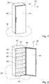
- FIG. 1 shows a home appliance 34 comprising a home appliance device 10, in a schematic perspective view.
- the home appliance 34 is embodied as a home chiller appliance.
- the home appliance device 10 is embodied as a home chiller appliance device.
- the home appliance 34 is embodied as a refrigerator.
- the home appliance 34 could further be embodied in particular as a wine cooler, a climate cabinet, an ice-box, a freezer and/or a refrigerator-freezer combination.
- FIG 1 the home appliance device 10 is shown in an installation position.
- the home appliance device 10 is installed on a base 38.
- the base 38 defines a substantially horizontal plane.
- the home appliance device 10 comprises an appliance body 40.
- the appliance body 40 partly defines an appliance housing.
- the appliance body 40 is installed on the base 38 substantially upright.
- the appliance body 40 partly defines a storage space 42.
- the appliance body 40 comprises walls 44, 46, 48, 50.
- the walls 44, 46, 48, 50 delimit the storage space 42.
- the appliance body 40 comprises two lateral walls 44, preferably opposite each other.
- the appliance body 40 comprises a rear wall 46.
- the appliance body 40 comprises a bottom wall 48.
- the appliance body 40 comprises a top wall 50, preferably opposite the bottom wall 48.
- the home appliance device 10 comprises at least one insert 52.
- the home appliance device 10 comprises six inserts 52. It is conceivable that the home appliance device 10 may comprise a differing number of inserts 52 as is deemed advantageous by someone skilled in the art.
- the home appliance device 10 may preferably comprise a combination of different embodiments of inserts 52, for example at least one insert 52 embodied as a shelf and at least one further insert 52 embodied as a bottle holder. For the sake of clarity, in the following only one insert 52 is given a reference numeral and is described in detail. The following description may be transferred to further inserts 52 accordingly.
- the home appliance device 10 comprises at least one appliance door 54.
- the home appliance device 10 comprises an appliance door 54.
- the appliance door 54 is connected to the appliance body 40. In a mounted state, the appliance door 54 is rotatably connected to the appliance body 40.
- the home appliance device 10 comprises one first gearing element 12 (cf. figures 3 to 5 ).
- the first gearing element 12 is rotatable around a first rotation axis 14.
- the first rotation axis 14 is substantially vertical.
- the first rotation axis 14 is substantially perpendicular to the base 38.
- the first gearing element 12 engages a second gearing element 16 of the home appliance device 10.
- the home appliance device 10 comprises the second gearing element 16 (compare figures 3 to 5 ).
- the second gearing element 16 is rotatable around a second rotation axis 18.
- the second rotation axis 18 is substantially horizontal.
- the second rotation axis 18 is substantially parallel to the base 38.
- the second rotation axis 18 is perpendicular to the first rotation axis 14.
- the home appliance device 10 comprises a housing unit 20.
- the housing unit 20 mostly covers the first gearing element 12. In a mounted state, the housing unit 20 mostly covers the second gearing element 16.
- the housing unit 20 comprises a housing element 22.
- the housing element 22 mostly covers the first gearing element 12. In a mounted state, the housing element 22 is latched with the first gearing element 12.
- the housing element 22 supports the first gearing element 12.
- the housing element 22 has two legs 26, 28.
- the legs 26, 28 are arranged opposite each other. In a mounted state, the first gearing element 12 is supported by means of the legs 26, 28.
- the housing element 22 is substantially U-shaped.
- the housing element 22 has a section 56.
- the section 56 connects the legs 26, 28 to each other.
- the section 56 forms the bottom of the U-shape of the housing element 22.
- the housing element 22 mostly encompasses the first gearing element 12.
- the housing element 22 mostly encompasses the second gearing element 16.
- the second gearing element 16 is mostly arranged between the first gearing element 12 and the section 56 of the housing element 22.
- the first gearing element 12 fixes the second gearing element 16 in position.
- the second gearing element 16 is mostly indirectly clamped between the first gearing element 12 and the section 56 of the housing element 22. In a mounted state, the second gearing element 16 is mostly directly clamped between the first gearing element 12 and a section 58 of a further housing element 24 of the housing unit 20.
- the housing unit 20 comprises the further housing element 24.
- the further housing element 24 comprises the further section 58. In a mounted state, the further housing element 24 is mostly arranged inside the housing element 22.
- the housing element 22 mostly encompasses the further housing element 24.
- the further section 58 of the further housing element 24 is mostly arranged between the second gearing element 16 and the section 56 of the housing element 22.
- the further housing element 24 supports the second gearing element 16.
- the further housing element 24 has two further legs 30, 32.
- the further legs 30, 32 are arranged opposite to each other. In a mounted state, the second gearing element 16 is supported by means of the further legs 30, 32.
- the further housing element 24 is substantially U-shaped.
- the further section 58 connects the further legs 30, 32 to each other.
- the further section 58 forms the bottom of the U-shape of the further housing element 24.
- the further housing element 24 comprises at least one further projection 60.
- the further housing element 24 comprises four further projections 60.
- the further projections 60 are located at the further legs 30, 32 of the further housing element 24.
- the housing element 22 comprises at least one recess 62.
- the housing element 22 comprises four recesses 62.
- the recesses 62 are located at the legs 26, 28 of the housing element 22.
- the further projections 60 of the further housing element 24 engage into the recesses 62 of the housing element 22.
- the U-shape of the housing element 22 and the U-shape of the further housing element 24 are oriented at an angle of substantially 90° with respect to one another.
- the legs 26, 28 of the housing element 22 and the further legs 30, 32 of the further housing element 24 are oriented substantially perpendicular with respect to each other.
- the further housing element 24 supports the second gearing element 16.
- the second gearing element 16 is loosely arranged inside the further housing element 24 in a pre-assembled state.
- the second gearing element 16 is mostly arranged inside the further housing element 24.
- the second gearing element 16 is inserted into the further housing element 24 in an assembly direction 74.
- the second gearing element 16 forms a pre-assembly group 36 together with the further housing element 24 (cf. figure 3 ).
- the pre-assembly group 36 and the first gearing element 12 are mostly arranged inside the housing element 22.
- the pre-assembly group 36 and the first gearing element 12 are inserted into the housing element 22 in a further assembly direction 76.
- the pre-assembly group 36 and the first gearing element 12 are latched with the housing element 22.
- the pre-assembly group 36 and the first gearing element 12 and the housing element 22 form a further pre-assembly group 72.
- the further pre-assembly group 72 may in particular be fixed in position, preferably to the appliance body 40, by means of at least one rivet, for example by means of four rivets.
- the first gearing element 12, the second gearing element 16 and the housing unit 20, which in particular comprises the housing element 22 and the further housing element 24, are part of a height adjusting mechanism (cf. figure 5 ).
- the height adjusting mechanism is provided for adjusting a height of the appliance body 40 with respect to the base 38.
- the home appliance device 10 comprises an operating element 64.
- the operating element 64 is connected to the first gearing element 12 in a torque proof fashion.
- the operating element 64 is rotatable clockwise and counterclockwise. By rotating the operating element 64 the first gearing element 12 is rotated.
- the first gearing element 12 transfers the rotation to the second gearing element 16.
- the home appliance device 10 comprises a supporting element 66.
- the supporting element 66 is connected to the second gearing element 16 in a torque proof fashion. By rotating the supporting element 66 the second gearing element 16 is rotated.
- the home appliance device 10 comprises a stand element 68.
- the stand element 68 In a mounting position, the stand element 68 is located on the base 38.
- the stand element 68 and the supporting element 66 are connected to one another.
- the home appliance device 10 comprises a gearing 70.
- the gearing 70 connects the stand element 68 and the supporting element 66 to one another.
- a gearing position of the supporting element 66 with respect to the stand element 68 changes.
- the gearing position of the supporting element 66 with respect to the stand element 68 is changed.
- the height adjusting mechanism may in particular be configured for the height adjustment of a front floor support stand and/or of a back floor support stand.
- the housing unit 20, in particular the housing element 22 and/or the further housing element 24, may in particular be made at least mostly of metal and preferably of sheet metal.
Landscapes
- Engineering & Computer Science (AREA)
- General Engineering & Computer Science (AREA)
- Mechanical Engineering (AREA)
- Chemical & Material Sciences (AREA)
- Combustion & Propulsion (AREA)
- Physics & Mathematics (AREA)
- Thermal Sciences (AREA)
- Devices That Are Associated With Refrigeration Equipment (AREA)
- Refrigerator Housings (AREA)
- Casings For Electric Apparatus (AREA)
Abstract
Description
- The invention relates to a home appliance device, in particular a home chiller appliance device and to a method for assembly of a home appliance device.
- From the international patent application
WO 2015/078511 A1 , a home appliance device is known comprising one first gearing element that is rotatable around a first rotation axis. One second gearing element is rotatable around a second rotation axis which is perpendicular to the first rotation axis. The first gearing element and the second gearing element are inserted in a housing unit that is embodied as one single element. The home appliance device is configured for adjusting a height of a home appliance. - An objective of the invention is, in particular, to provide a home appliance device with improved characteristics regarding a simple construction. This objective is achieved, according to the invention, by the features of claims 1, 4 and 15, while further implementations and further developments of the invention may be gathered from the dependent claims.
- A home appliance device, in particular a home chiller appliance device, is proposed, which is in particular configured for adjusting a height of a home appliance, comprising: at least one first gearing element that is rotatable around a first rotation axis; at least one second gearing element that is rotatable around a second rotation axis which is perpendicular to the first rotation axis; and at least one housing unit at least mostly covering the first gearing element and comprising at least one housing element that is latched with the first gearing element.
- By a "home appliance device" is in particular to be understood at least a portion, preferably a sub-assembly group, of a home appliance. The home appliance is in particular provided for storing and preferably tempering victuals such as beverages, meat, fish, vegetables, fruits, milk and/or dairy products in at least one operating state, advantageously for the purpose of enhancing a storage time of the stored victuals. For example, the home appliance is embodied as a home chiller appliance, which is in at least one operating state configured for cooling victuals. The home chiller appliance could in particular be embodied as a climate cabinet, an ice-box, a refrigerator, a freezer, a refrigerator-freezer combination and/or a wine cooler. However, the home appliance could also be embodied as a home appliance for warming up and in particular for cooking victuals, e.g. an oven and/or a steamer and/or a microwave. Alternatively the home appliance could also be embodied as a home appliance for cleaning, e.g. a washing machine and/or a dryer and/or dishwasher. The home appliance may in particular comprise at least two, in particular at least three and preferably at least four home appliance devices.
- By a "gearing element" is in particular to be understood an element transferring and/or altering at least one kinetic momentum in at least one operating state. The kinetic momentum may in particular be a force and/or a momentum of force. The gearing element may in particular have an at least substantially cylindrical shape and may in particular have at least one toothing at its outer surface. In particular, the gearing element could be part of a worm gear and/or a spur gearing and/or a helical gear. In at least one operating state the first gearing element and the second gearing element mesh with one another. The gearing element may in particular be made at least mostly of metal and preferably of a brass alloy. In this context, "perpendicular" is to mean at least substantially perpendicular and/or perpendicular in the technical sense, meaning in particular that rounding errors and/or manufacturing tolerances are considered. In this context, "at least substantially perpendicular" is in particular to be understood as an orientation of a direction with respect to a reference direction, in particular in a plane, wherein the direction and the reference direction include an angle of 90°, the orientation in particular having a deviation of less than 15°, advantageously of less than 10° and particularly advantageously of less than 2°.
- The term "at least mostly" with reference to an object is in particular to mean by more than 50 % or by more than 65 % or by more than 80 % or by more than 95 % of the object, in particular of a surface area and/or of a volume and/or of a mass of the object. The first gearing element and the housing element may be connected to one another by means of a manually detachable connection. By the wording that a first object is "latched" with a second object and/or the wording that a first object and a second object are "latched" with each other is in particular to be understood that at least one part of one of the objects is deflected in at least one assembly procedure and afterwards engages behind at least one further part of the other one of the objects.
- In this context, "configured" is in particular to mean specifically programmed, designed and/or equipped. By an object being configured for a certain function is in particular to be understood that the object implements and/or fulfills said certain function in at least one application state and/or operating state.
- By means of the invention, in particular a simple construction of the home appliance device can be achieved. It is in particular possible to assemble and/or disassemble the first gearing element and the housing element in a simple and/or fast way, whereby low manufacturing costs can be achieved. This allows general usage for all similar implementations of appliances. Additionally a solution for a new concept design can be provided. Moreover, delicate electronical devices can in particular be protected from impacts. In particular, a mechanical lock for plug-in electronical devices can be provided. Problems for insolation air leakage and wiring harness damages can in particular be eliminated. In particular an easy height adjustment and/or an easy serviceability can be provided. A volume can in particular be kept small.
- For example, the housing element could at least mostly encompass the first gearing element only. Also the housing element may at least mostly encompasses the first gearing element and the second gearing element. As a result of this, the first gearing element and the second gearing element can in particular be located safely and/or protected, thus prolonging a life span of the first gearing element and the second gearing element.
- In a further implementation of the invention, which can be considered on its own or in combination with other aspects of the invention, a home appliance device, in particular a home chiller appliance device, is proposed, comprising: at least one first gearing element that is rotatable around a first rotation axis; at least one second gearing element that is rotatable around a second rotation axis which is perpendicular to the first rotation axis; and at least one housing unit at least partly covering the first gearing element and comprising at least one housing element, the first gearing element fixing the second gearing element in position. The first gearing element in particular may prevent a translational movement of the second gearing element in at least one direction. The first gearing element may reduce the degree of freedom for a translational movement of the second gearing element at least in one direction. On account of this, in particular a fixing device for fixing the second gearing element in position can be dispensed with, whereby low costs can be achieved.
- Additionally, it is proposed that the second gearing element may at least be mostly arranged between the first gearing element and at least one section of the housing element. The second gearing element may in particular be pressed and/or jammed, directly and/or indirectly, between the first gearing element and the section of the housing element. On account of this, stability can in particular be improved.
- Possibly the housing unit could comprise only the housing element and be in particular free of further housing elements. The housing element could in particular support the first gearing element and the second gearing element. Alternatively, the housing unit comprises at least one further housing element which supports at least the second gearing element. As a result of this, a high level of stability can in particular be achieved.
- Furthermore, it is proposed that the housing element may at least mostly encompasses the further housing element. On account of this, stability can in particular be increased.
- In addition, it is proposed that the housing element and the further housing element may be latched with each other. As a result of this, a fast and/or easy assembly procedure can in particular be achieved. In particular, a movement of the housing element and of the further housing element with respect to each other can be prevented, as a result of which stability can in particular be improved.
- For example the second gearing element could be located directly contacting the first gearing element and the section of the housing element. Preferably at least one section of the further housing element is at least mostly arranged between the second gearing element and at least one section of the housing element. There may exist in particular a line of force between the first gearing element, the second gearing element, the section of the further housing element and the section of the housing element. On account of this, a compact implementation can in particular be provided.
- Possibly the second gearing element could be latched with the further housing element in a pre-assembled state. The second gearing element could also be loosely arranged inside the further housing element in a pre-assembled state. The second gearing element can in particular be moved with respect to the further housing element in an easy manner in the pre-assembled state. As a result of this, a fast and/or easy mounting procedure can in particular be achieved, thus saving manufacturing costs and/or manufacturing time. In particular, there is no need to use any additional fixing component for an assembly process.
- Further, it is proposed that the housing element may at least be substantially U-shaped and may have at least two legs. In this context, "at least substantially U-shaped" is to mean U-shaped in the technical sense, meaning in particular that rounding errors and/or manufacturing tolerances are considered. On account of this, the housing element can in particular be manufactured in an easy and/or fast manner.
- Additionally, it is proposed that the further housing element may be at least substantially U-shaped and may have at least two further legs. As a result of this, the manufacturing process can in particular be accelerated.
- In a further implementation of the invention at least one of the legs and at least one of the further legs may be oriented at least substantially perpendicularly with respect to each other. A first one of the legs of a first one of the housing elements may in particular be at least substantially perpendicular to both legs of a second one of the housing elements. In at least one cross-sectional plane the legs of the housing elements may in particular form an at least substantially rectangular shape. On account of this, a compact embodiment and/or a very high level of stability can in particular be provided.
- A very simple construction can in particular be achieved by a home appliance, in particular by a home chiller appliance, comprising at least one home appliance device according to the invention.
- A fast manufacturing process can in particular be achieved by a method for assembly of a home appliance device, the home appliance device comprising: at least one first gearing element that is rotatable around a first rotation axis; at least one second gearing element that is rotatable around a second rotation axis which is perpendicular to the first rotation axis; and at least one housing unit at least partly covering the first gearing element and having at least one housing element and at least one further housing element, the second gearing element being at least mostly arranged inside the further housing element and forming a pre-assembly group together with the further housing element, the pre-assembly group and the first gearing element being at least mostly arranged inside the housing element and latched with the housing element.
- Herein the home appliance device is not to be limited to the application and implementation described above. In particular, for the purpose of fulfilling a functionality herein described, the home appliance device may comprise a number of respective elements, structural components and units that differs from the number mentioned herein. Furthermore, regarding the value ranges mentioned in this disclosure, values within the limits mentioned are to be understood to be also disclosed and to be used as applicable.
- Further advantages may become apparent from the following description of the drawing. In the drawing an exemplary embodiment of the invention is shown. The drawing, the description and the claims contain a plurality of features in combination. The person having ordinary skill in the art will purposefully also consider the features separately and will find further expedient combinations.
- If there is more than one specimen of a certain object, only one of these is given a reference numeral in the figures and in the description. The description of this specimen may be correspondingly transferred to the other specimens of the object.
-
- Fig. 1
- a home appliance comprising a home appliance device in an operating state, in a schematic front view,
- Fig. 2
- the home appliance comprising the home appliance device in an opened state, in a schematic front view,
- Fig. 3
- a first gearing element, a second gearing element and a housing unit of the home appliance device, in a schematic exploded view,
- Fig. 4
- the first gearing element, the second gearing element and the housing unit in a mounted state, in a schematic view, and
- Fig. 5
- the first gearing element, the second gearing element, the housing unit and an appliance body of the home appliance device in a mounted state, in a schematic view.
-
Figure 1 shows ahome appliance 34 comprising ahome appliance device 10, in a schematic perspective view. Thehome appliance 34 is embodied as a home chiller appliance. Thehome appliance device 10 is embodied as a home chiller appliance device. - In present embodiment the
home appliance 34 is embodied as a refrigerator. Thehome appliance 34 could further be embodied in particular as a wine cooler, a climate cabinet, an ice-box, a freezer and/or a refrigerator-freezer combination. - In
figure 1 thehome appliance device 10 is shown in an installation position. Thehome appliance device 10 is installed on abase 38. Thebase 38 defines a substantially horizontal plane. - The
home appliance device 10 comprises anappliance body 40. Theappliance body 40 partly defines an appliance housing. Theappliance body 40 is installed on the base 38 substantially upright. - The
appliance body 40 partly defines astorage space 42. Theappliance body 40 compriseswalls walls storage space 42. Theappliance body 40 comprises twolateral walls 44, preferably opposite each other. Theappliance body 40 comprises arear wall 46. Theappliance body 40 comprises abottom wall 48. Theappliance body 40 comprises atop wall 50, preferably opposite thebottom wall 48. - The
home appliance device 10 comprises at least oneinsert 52. In the present case thehome appliance device 10 comprises six inserts 52. It is conceivable that thehome appliance device 10 may comprise a differing number ofinserts 52 as is deemed advantageous by someone skilled in the art. Thehome appliance device 10 may preferably comprise a combination of different embodiments ofinserts 52, for example at least oneinsert 52 embodied as a shelf and at least onefurther insert 52 embodied as a bottle holder. For the sake of clarity, in the following only oneinsert 52 is given a reference numeral and is described in detail. The following description may be transferred tofurther inserts 52 accordingly. - The
home appliance device 10 comprises at least oneappliance door 54. In the present case thehome appliance device 10 comprises anappliance door 54. Theappliance door 54 is connected to theappliance body 40. In a mounted state, theappliance door 54 is rotatably connected to theappliance body 40. - The
home appliance device 10 comprises one first gearing element 12 (cf.figures 3 to 5 ). Thefirst gearing element 12 is rotatable around afirst rotation axis 14. In present embodiment thefirst rotation axis 14 is substantially vertical. Thefirst rotation axis 14 is substantially perpendicular to thebase 38. In a mounted state, thefirst gearing element 12 engages asecond gearing element 16 of thehome appliance device 10. - The
home appliance device 10 comprises the second gearing element 16 (comparefigures 3 to 5 ). Thesecond gearing element 16 is rotatable around asecond rotation axis 18. In the present embodiment thesecond rotation axis 18 is substantially horizontal. Thesecond rotation axis 18 is substantially parallel to thebase 38. Thesecond rotation axis 18 is perpendicular to thefirst rotation axis 14. - The
home appliance device 10 comprises ahousing unit 20. Thehousing unit 20 mostly covers thefirst gearing element 12. In a mounted state, thehousing unit 20 mostly covers thesecond gearing element 16. - The
housing unit 20 comprises ahousing element 22. Thehousing element 22 mostly covers thefirst gearing element 12. In a mounted state, thehousing element 22 is latched with thefirst gearing element 12. - The
housing element 22 supports thefirst gearing element 12. Thehousing element 22 has twolegs legs first gearing element 12 is supported by means of thelegs - The
housing element 22 is substantially U-shaped. Thehousing element 22 has asection 56. Thesection 56 connects thelegs section 56 forms the bottom of the U-shape of thehousing element 22. - The
housing element 22 mostly encompasses thefirst gearing element 12. Thehousing element 22 mostly encompasses thesecond gearing element 16. In a mounted state, thesecond gearing element 16 is mostly arranged between thefirst gearing element 12 and thesection 56 of thehousing element 22. - The
first gearing element 12 fixes thesecond gearing element 16 in position. Thesecond gearing element 16 is mostly indirectly clamped between thefirst gearing element 12 and thesection 56 of thehousing element 22. In a mounted state, thesecond gearing element 16 is mostly directly clamped between thefirst gearing element 12 and asection 58 of afurther housing element 24 of thehousing unit 20. - The
housing unit 20 comprises thefurther housing element 24. Thefurther housing element 24 comprises thefurther section 58. In a mounted state, thefurther housing element 24 is mostly arranged inside thehousing element 22. Thehousing element 22 mostly encompasses thefurther housing element 24. - In a mounted state, the
further section 58 of thefurther housing element 24 is mostly arranged between thesecond gearing element 16 and thesection 56 of thehousing element 22. - The
further housing element 24 supports thesecond gearing element 16. Thefurther housing element 24 has twofurther legs further legs second gearing element 16 is supported by means of thefurther legs - The
further housing element 24 is substantially U-shaped. Thefurther section 58 connects thefurther legs further section 58 forms the bottom of the U-shape of thefurther housing element 24. - In a mounted state, the
housing element 22 and thefurther housing element 24 are latched with each other. Thefurther housing element 24 comprises at least onefurther projection 60. In the present embodiment thefurther housing element 24 comprises fourfurther projections 60. Thefurther projections 60 are located at thefurther legs further housing element 24. - The
housing element 22 comprises at least onerecess 62. In present embodiment thehousing element 22 comprises fourrecesses 62. Therecesses 62 are located at thelegs housing element 22. In a mounted state, thefurther projections 60 of thefurther housing element 24 engage into therecesses 62 of thehousing element 22. - In a mounted state, the U-shape of the
housing element 22 and the U-shape of thefurther housing element 24 are oriented at an angle of substantially 90° with respect to one another. Thelegs housing element 22 and thefurther legs further housing element 24 are oriented substantially perpendicular with respect to each other. - In a pre-assembled state, the
further housing element 24 supports thesecond gearing element 16. Thesecond gearing element 16 is loosely arranged inside thefurther housing element 24 in a pre-assembled state. - In a method for assembly of the
home appliance device 10, thesecond gearing element 16 is mostly arranged inside thefurther housing element 24. Thesecond gearing element 16 is inserted into thefurther housing element 24 in anassembly direction 74. Thesecond gearing element 16 forms apre-assembly group 36 together with the further housing element 24 (cf.figure 3 ). - The
pre-assembly group 36 and thefirst gearing element 12 are mostly arranged inside thehousing element 22. Thepre-assembly group 36 and thefirst gearing element 12 are inserted into thehousing element 22 in afurther assembly direction 76. Thepre-assembly group 36 and thefirst gearing element 12 are latched with thehousing element 22. - The
pre-assembly group 36 and thefirst gearing element 12 and thehousing element 22 form a furtherpre-assembly group 72. The furtherpre-assembly group 72 may in particular be fixed in position, preferably to theappliance body 40, by means of at least one rivet, for example by means of four rivets. - The
first gearing element 12, thesecond gearing element 16 and thehousing unit 20, which in particular comprises thehousing element 22 and thefurther housing element 24, are part of a height adjusting mechanism (cf.figure 5 ). The height adjusting mechanism is provided for adjusting a height of theappliance body 40 with respect to thebase 38. - The
home appliance device 10 comprises an operatingelement 64. The operatingelement 64 is connected to thefirst gearing element 12 in a torque proof fashion. The operatingelement 64 is rotatable clockwise and counterclockwise. By rotating the operatingelement 64 thefirst gearing element 12 is rotated. - The
first gearing element 12 transfers the rotation to thesecond gearing element 16. Thehome appliance device 10 comprises a supportingelement 66. The supportingelement 66 is connected to thesecond gearing element 16 in a torque proof fashion. By rotating the supportingelement 66 thesecond gearing element 16 is rotated. - The
home appliance device 10 comprises astand element 68. In a mounting position, thestand element 68 is located on thebase 38. Thestand element 68 and the supportingelement 66 are connected to one another. - The
home appliance device 10 comprises agearing 70. Thegearing 70 connects thestand element 68 and the supportingelement 66 to one another. By rotation of the supporting element 66 a gearing position of the supportingelement 66 with respect to thestand element 68 changes. By changing the gearing position of the supportingelement 66 with respect to thestand element 68, the height of theappliance body 40 with respect to thebase 38 is changed. - The height adjusting mechanism may in particular be configured for the height adjustment of a front floor support stand and/or of a back floor support stand. The
housing unit 20, in particular thehousing element 22 and/or thefurther housing element 24, may in particular be made at least mostly of metal and preferably of sheet metal. - The following is a summary list of reference numerals and the corresponding structure used in the above description of the invention:
- 10
- Home appliance device
- 12
- First gearing element
- 14
- First rotation axis
- 16
- Second gearing element
- 18
- Second rotation axis
- 20
- Housing unit
- 22
- Housing element
- 24
- Further housing element
- 26
- Leg
- 28
- Leg
- 30
- Further leg
- 32
- Further leg
- 34
- Home appliance
- 36
- Pre-assembly group
- 38
- Base
- 40
- Appliance body
- 42
- Storage space
- 44
- Wall
- 46
- Wall
- 48
- Wall
- 50
- Wall
- 52
- Insert
- 54
- Appliance door
- 56
- Section
- 58
- Section
- 60
- Further projection
- 62
- Recess
- 64
- Operating element
- 66
- Supporting element
- 68
- Stand element
- 70
- Gearing
- 72
- Further pre-assembly group
- 74
- Assembly direction
- 76
- Further assembly direction
Claims (15)
- A home appliance device, in particular a home chiller appliance device, comprising: at least one first gearing element that is rotatable around a first rotation axis; at least one second gearing element that is rotatable around a second rotation axis which is perpendicular to the first rotation axis; and at least one housing unit at least mostly covering the first gearing element and having at least one housing element that is latched with the first gearing element.
- The home appliance device according to claim 1, the housing element at least mostly encompassing the first gearing element and the second gearing element.
- The home appliance device according to claim 1, the first gearing element fixing the second gearing element in position.
- A home appliance device, in particular a home chiller appliance device, comprising: at least one first gearing element that is rotatable around a first rotation axis; at least one second gearing element that is rotatable around a second rotation axis which is perpendicular to the first rotation axis; and at least one housing unit at least partly covering the first gearing element and having at least one housing element, the first gearing element fixing the second gearing element in position.
- The home appliance device according to claim 1 or claim 4, the second gearing element being at least mostly arranged between the first gearing element and at least one section of the housing element.
- The home appliance device according to claim 1 or claim 4, the housing unit comprising at least one further housing element which supports at least the second gearing element.
- The home appliance device according to claim 6, the housing element at least mostly encompassing the further housing element.
- The home appliance device according to claim 6, the housing element and the further housing element being latched with each other.
- The home appliance device according to claim 6, at least one section of the further housing element being at least mostly arranged between the second gearing element and at least one section of the housing element.
- The home appliance device according to claim 6, the second gearing element being loosely arranged inside the further housing element in a pre-assembled state.
- The home appliance device according to claim 1 or claim 4, the housing element being at least substantially U-shaped and having at least two legs.
- The home appliance device at least according to claim 6, the further housing element being at least substantially U-shaped and having at least two further legs.
- The home appliance device according to claims 11 and 12, at least one of the legs and at least one of the further legs being oriented at least substantially perpendicular with respect to each other.
- A home appliance, in particular a home chiller appliance, comprising at least one home appliance device according to claim 1 or claim 4.
- A method for assembly of a home appliance device, in particular according to claim 1 or claim 4, the home appliance device comprising: at least one first gearing element that is rotatable around a first rotation axis; at least one second gearing element that is rotatable around a second rotation axis which is perpendicular to the first rotation axis; and at least one housing unit at least partly covering the first gearing element and having at least one housing element and at least one further housing element, the second gearing element being at least mostly arranged inside the further housing element and forming a pre-assembly group together with the further housing element, the pre-assembly group and the first gearing element being at least mostly arranged inside the housing element and latched with the housing element.
Applications Claiming Priority (1)
| Application Number | Priority Date | Filing Date | Title |
|---|---|---|---|
| US15/357,416 US9803730B1 (en) | 2016-11-21 | 2016-11-21 | Home appliance device |
Publications (2)
| Publication Number | Publication Date |
|---|---|
| EP3323316A1 true EP3323316A1 (en) | 2018-05-23 |
| EP3323316B1 EP3323316B1 (en) | 2019-08-07 |
Family
ID=60142559
Family Applications (1)
| Application Number | Title | Priority Date | Filing Date |
|---|---|---|---|
| EP17198911.4A Active EP3323316B1 (en) | 2016-11-21 | 2017-10-27 | Home appliance device |
Country Status (3)
| Country | Link |
|---|---|
| US (1) | US9803730B1 (en) |
| EP (1) | EP3323316B1 (en) |
| CN (1) | CN108088141A (en) |
Citations (4)
| Publication number | Priority date | Publication date | Assignee | Title |
|---|---|---|---|---|
| DE19528901A1 (en) * | 1995-08-05 | 1997-02-06 | Az Ausruest Zubehoer Gmbh | Adjustable foot for furniture or domestic apparatus e.g. dishwasher or washing machine - has housing attached to apparatus, and contains nut running on threaded shaft with footplate, plus slipping clutch to adjust it |
| DE19606460A1 (en) * | 1996-02-21 | 1997-08-28 | Bosch Siemens Hausgeraete | Height adjusting device for household appliance foot |
| EP2519680A1 (en) * | 2009-12-31 | 2012-11-07 | Arçelik Anonim Sirketi | A household appliance |
| WO2015078511A1 (en) | 2013-11-29 | 2015-06-04 | Arcelik Anonim Sirketi | Height adjustable foot for household appliance |
Family Cites Families (14)
| Publication number | Priority date | Publication date | Assignee | Title |
|---|---|---|---|---|
| US1417639A (en) * | 1921-03-19 | 1922-05-30 | Daniel L Sterner | Table leveler |
| US1632383A (en) * | 1926-04-09 | 1927-06-14 | Seiden Samuel | Leveling device |
| US4991805A (en) * | 1989-05-17 | 1991-02-12 | Whirlpool Corporation | Refrigerator gear driven leveling system |
| US6729590B2 (en) * | 2002-01-23 | 2004-05-04 | Edward Gabriel | Leveling device |
| US6910665B2 (en) * | 2003-03-12 | 2005-06-28 | Maytag Corporation | Integrated refrigerator cabinet leveling and door closing assembly |
| TR200600446T1 (en) * | 2003-06-04 | 2006-08-21 | Ar�El�K Anon�M ��Rket� | A household appliance |
| DE102004022681B3 (en) * | 2004-05-05 | 2005-09-22 | Miele & Cie. Kg | Height-adjustable foot for home appliances, such as washing or dishwashing machine with a shaft which is equipped on the stand side with a foot plate |
| DE102004050362A1 (en) * | 2004-10-15 | 2006-04-27 | BSH Bosch und Siemens Hausgeräte GmbH | Adjusting device, in particular for a leveling foot of a household appliance |
| EP1895040B1 (en) * | 2006-08-29 | 2008-11-05 | Bonferraro S.p.A. | System for adjusting the height of a built-in household appliance, in particular a washing machine |
| DE102007057511B3 (en) * | 2007-11-29 | 2009-07-16 | BSH Bosch und Siemens Hausgeräte GmbH | Household appliance with a height adjustment device for a device foot |
| IT1392975B1 (en) * | 2009-02-17 | 2012-04-02 | Illinois Tool Works | ADJUSTABLE FEET, IN PARTICULAR A REAR FOOT, FOR A HOUSEHOLD APPLIANCE |
| KR102030845B1 (en) * | 2012-11-13 | 2019-10-11 | 삼성전자주식회사 | Refrigerator and lower hinge module of the same |
| US9572429B2 (en) * | 2013-05-03 | 2017-02-21 | Arcelik Anonim Sirketi | Household appliance having improved height profile adjustable feet |
| US10006582B2 (en) * | 2014-11-03 | 2018-06-26 | Arcelik Anonim Sirketi | Household appliance with control height adjustment mechanism |
-
2016
- 2016-11-21 US US15/357,416 patent/US9803730B1/en active Active
-
2017
- 2017-10-27 EP EP17198911.4A patent/EP3323316B1/en active Active
- 2017-11-17 CN CN201711145556.XA patent/CN108088141A/en active Pending
Patent Citations (4)
| Publication number | Priority date | Publication date | Assignee | Title |
|---|---|---|---|---|
| DE19528901A1 (en) * | 1995-08-05 | 1997-02-06 | Az Ausruest Zubehoer Gmbh | Adjustable foot for furniture or domestic apparatus e.g. dishwasher or washing machine - has housing attached to apparatus, and contains nut running on threaded shaft with footplate, plus slipping clutch to adjust it |
| DE19606460A1 (en) * | 1996-02-21 | 1997-08-28 | Bosch Siemens Hausgeraete | Height adjusting device for household appliance foot |
| EP2519680A1 (en) * | 2009-12-31 | 2012-11-07 | Arçelik Anonim Sirketi | A household appliance |
| WO2015078511A1 (en) | 2013-11-29 | 2015-06-04 | Arcelik Anonim Sirketi | Height adjustable foot for household appliance |
Also Published As
| Publication number | Publication date |
|---|---|
| EP3323316B1 (en) | 2019-08-07 |
| US9803730B1 (en) | 2017-10-31 |
| CN108088141A (en) | 2018-05-29 |
Similar Documents
| Publication | Publication Date | Title |
|---|---|---|
| US8579394B2 (en) | Refrigerator | |
| US10238209B2 (en) | Home appliance device with a door rack container and home appliance including the home appliance device | |
| US20180156534A1 (en) | Home appliance device | |
| CN102395846A (en) | Recessed shelf and drawer support for refrigerator | |
| EP3106790A1 (en) | Ice maker of a refrigerator and method of manufacturing the same | |
| US9863690B1 (en) | Home appliance door | |
| CN206891014U (en) | Home appliance device | |
| US10012430B2 (en) | Home appliance device | |
| EP3358281B1 (en) | Home appliance device | |
| US9803730B1 (en) | Home appliance device | |
| EP3399260A1 (en) | Home appliance device | |
| US11181313B2 (en) | Domestic appliance | |
| EP2370767A1 (en) | A cooling device comprising a height adjustable shelf | |
| EP3327378A1 (en) | Home appliance device | |
| EP3327381B1 (en) | Home appliance door | |
| EP1907776B1 (en) | A cooling device | |
| EP2433068B1 (en) | A cooling device | |
| US20100219147A1 (en) | Adjustable partition for bottom mount freezer | |
| TW202334596A (en) | Refrigerator | |
| US11029082B2 (en) | Household appliance apparatus, household appliance having the household appliance apparatus and method for mounting a household appliance apparatus | |
| EP3150945B1 (en) | Refrigerator having locking device for ice bucket and method for installation of locking device of ice bucket | |
| KR20100066865A (en) | Motor mounting member and tray assembly having this | |
| EP4453359B1 (en) | Electrical appliance comprising a hinge | |
| KR102163918B1 (en) | Refrigerator | |
| KR101623792B1 (en) | Refrigerator |
Legal Events
| Date | Code | Title | Description |
|---|---|---|---|
| PUAI | Public reference made under article 153(3) epc to a published international application that has entered the european phase |
Free format text: ORIGINAL CODE: 0009012 |
|
| STAA | Information on the status of an ep patent application or granted ep patent |
Free format text: STATUS: THE APPLICATION HAS BEEN PUBLISHED |
|
| AK | Designated contracting states |
Kind code of ref document: A1 Designated state(s): AL AT BE BG CH CY CZ DE DK EE ES FI FR GB GR HR HU IE IS IT LI LT LU LV MC MK MT NL NO PL PT RO RS SE SI SK SM TR |
|
| AX | Request for extension of the european patent |
Extension state: BA ME |
|
| STAA | Information on the status of an ep patent application or granted ep patent |
Free format text: STATUS: REQUEST FOR EXAMINATION WAS MADE |
|
| 17P | Request for examination filed |
Effective date: 20181123 |
|
| RBV | Designated contracting states (corrected) |
Designated state(s): AL AT BE BG CH CY CZ DE DK EE ES FI FR GB GR HR HU IE IS IT LI LT LU LV MC MK MT NL NO PL PT RO RS SE SI SK SM TR |
|
| GRAP | Despatch of communication of intention to grant a patent |
Free format text: ORIGINAL CODE: EPIDOSNIGR1 |
|
| STAA | Information on the status of an ep patent application or granted ep patent |
Free format text: STATUS: GRANT OF PATENT IS INTENDED |
|
| INTG | Intention to grant announced |
Effective date: 20190329 |
|
| GRAS | Grant fee paid |
Free format text: ORIGINAL CODE: EPIDOSNIGR3 |
|
| GRAA | (expected) grant |
Free format text: ORIGINAL CODE: 0009210 |
|
| STAA | Information on the status of an ep patent application or granted ep patent |
Free format text: STATUS: THE PATENT HAS BEEN GRANTED |
|
| AK | Designated contracting states |
Kind code of ref document: B1 Designated state(s): AL AT BE BG CH CY CZ DE DK EE ES FI FR GB GR HR HU IE IS IT LI LT LU LV MC MK MT NL NO PL PT RO RS SE SI SK SM TR |
|
| REG | Reference to a national code |
Ref country code: GB Ref legal event code: FG4D |
|
| REG | Reference to a national code |
Ref country code: CH Ref legal event code: EP Ref country code: AT Ref legal event code: REF Ref document number: 1162519 Country of ref document: AT Kind code of ref document: T Effective date: 20190815 |
|
| REG | Reference to a national code |
Ref country code: DE Ref legal event code: R096 Ref document number: 602017005911 Country of ref document: DE |
|
| REG | Reference to a national code |
Ref country code: IE Ref legal event code: FG4D |
|
| REG | Reference to a national code |
Ref country code: NL Ref legal event code: MP Effective date: 20190807 |
|
| REG | Reference to a national code |
Ref country code: LT Ref legal event code: MG4D |
|
| PG25 | Lapsed in a contracting state [announced via postgrant information from national office to epo] |
Ref country code: FI Free format text: LAPSE BECAUSE OF FAILURE TO SUBMIT A TRANSLATION OF THE DESCRIPTION OR TO PAY THE FEE WITHIN THE PRESCRIBED TIME-LIMIT Effective date: 20190807 Ref country code: LT Free format text: LAPSE BECAUSE OF FAILURE TO SUBMIT A TRANSLATION OF THE DESCRIPTION OR TO PAY THE FEE WITHIN THE PRESCRIBED TIME-LIMIT Effective date: 20190807 Ref country code: NO Free format text: LAPSE BECAUSE OF FAILURE TO SUBMIT A TRANSLATION OF THE DESCRIPTION OR TO PAY THE FEE WITHIN THE PRESCRIBED TIME-LIMIT Effective date: 20191107 Ref country code: PT Free format text: LAPSE BECAUSE OF FAILURE TO SUBMIT A TRANSLATION OF THE DESCRIPTION OR TO PAY THE FEE WITHIN THE PRESCRIBED TIME-LIMIT Effective date: 20191209 Ref country code: SE Free format text: LAPSE BECAUSE OF FAILURE TO SUBMIT A TRANSLATION OF THE DESCRIPTION OR TO PAY THE FEE WITHIN THE PRESCRIBED TIME-LIMIT Effective date: 20190807 Ref country code: BG Free format text: LAPSE BECAUSE OF FAILURE TO SUBMIT A TRANSLATION OF THE DESCRIPTION OR TO PAY THE FEE WITHIN THE PRESCRIBED TIME-LIMIT Effective date: 20191107 Ref country code: NL Free format text: LAPSE BECAUSE OF FAILURE TO SUBMIT A TRANSLATION OF THE DESCRIPTION OR TO PAY THE FEE WITHIN THE PRESCRIBED TIME-LIMIT Effective date: 20190807 Ref country code: HR Free format text: LAPSE BECAUSE OF FAILURE TO SUBMIT A TRANSLATION OF THE DESCRIPTION OR TO PAY THE FEE WITHIN THE PRESCRIBED TIME-LIMIT Effective date: 20190807 |
|
| REG | Reference to a national code |
Ref country code: AT Ref legal event code: MK05 Ref document number: 1162519 Country of ref document: AT Kind code of ref document: T Effective date: 20190807 |
|
| PG25 | Lapsed in a contracting state [announced via postgrant information from national office to epo] |
Ref country code: IS Free format text: LAPSE BECAUSE OF FAILURE TO SUBMIT A TRANSLATION OF THE DESCRIPTION OR TO PAY THE FEE WITHIN THE PRESCRIBED TIME-LIMIT Effective date: 20191207 Ref country code: LV Free format text: LAPSE BECAUSE OF FAILURE TO SUBMIT A TRANSLATION OF THE DESCRIPTION OR TO PAY THE FEE WITHIN THE PRESCRIBED TIME-LIMIT Effective date: 20190807 Ref country code: RS Free format text: LAPSE BECAUSE OF FAILURE TO SUBMIT A TRANSLATION OF THE DESCRIPTION OR TO PAY THE FEE WITHIN THE PRESCRIBED TIME-LIMIT Effective date: 20190807 Ref country code: GR Free format text: LAPSE BECAUSE OF FAILURE TO SUBMIT A TRANSLATION OF THE DESCRIPTION OR TO PAY THE FEE WITHIN THE PRESCRIBED TIME-LIMIT Effective date: 20191108 Ref country code: AL Free format text: LAPSE BECAUSE OF FAILURE TO SUBMIT A TRANSLATION OF THE DESCRIPTION OR TO PAY THE FEE WITHIN THE PRESCRIBED TIME-LIMIT Effective date: 20190807 Ref country code: ES Free format text: LAPSE BECAUSE OF FAILURE TO SUBMIT A TRANSLATION OF THE DESCRIPTION OR TO PAY THE FEE WITHIN THE PRESCRIBED TIME-LIMIT Effective date: 20190807 |
|
| PG25 | Lapsed in a contracting state [announced via postgrant information from national office to epo] |
Ref country code: TR Free format text: LAPSE BECAUSE OF FAILURE TO SUBMIT A TRANSLATION OF THE DESCRIPTION OR TO PAY THE FEE WITHIN THE PRESCRIBED TIME-LIMIT Effective date: 20190807 |
|
| PG25 | Lapsed in a contracting state [announced via postgrant information from national office to epo] |
Ref country code: PL Free format text: LAPSE BECAUSE OF FAILURE TO SUBMIT A TRANSLATION OF THE DESCRIPTION OR TO PAY THE FEE WITHIN THE PRESCRIBED TIME-LIMIT Effective date: 20190807 Ref country code: EE Free format text: LAPSE BECAUSE OF FAILURE TO SUBMIT A TRANSLATION OF THE DESCRIPTION OR TO PAY THE FEE WITHIN THE PRESCRIBED TIME-LIMIT Effective date: 20190807 Ref country code: AT Free format text: LAPSE BECAUSE OF FAILURE TO SUBMIT A TRANSLATION OF THE DESCRIPTION OR TO PAY THE FEE WITHIN THE PRESCRIBED TIME-LIMIT Effective date: 20190807 Ref country code: DK Free format text: LAPSE BECAUSE OF FAILURE TO SUBMIT A TRANSLATION OF THE DESCRIPTION OR TO PAY THE FEE WITHIN THE PRESCRIBED TIME-LIMIT Effective date: 20190807 Ref country code: IT Free format text: LAPSE BECAUSE OF FAILURE TO SUBMIT A TRANSLATION OF THE DESCRIPTION OR TO PAY THE FEE WITHIN THE PRESCRIBED TIME-LIMIT Effective date: 20190807 Ref country code: RO Free format text: LAPSE BECAUSE OF FAILURE TO SUBMIT A TRANSLATION OF THE DESCRIPTION OR TO PAY THE FEE WITHIN THE PRESCRIBED TIME-LIMIT Effective date: 20190807 |
|
| PG25 | Lapsed in a contracting state [announced via postgrant information from national office to epo] |
Ref country code: SK Free format text: LAPSE BECAUSE OF FAILURE TO SUBMIT A TRANSLATION OF THE DESCRIPTION OR TO PAY THE FEE WITHIN THE PRESCRIBED TIME-LIMIT Effective date: 20190807 Ref country code: IS Free format text: LAPSE BECAUSE OF FAILURE TO SUBMIT A TRANSLATION OF THE DESCRIPTION OR TO PAY THE FEE WITHIN THE PRESCRIBED TIME-LIMIT Effective date: 20200224 Ref country code: SM Free format text: LAPSE BECAUSE OF FAILURE TO SUBMIT A TRANSLATION OF THE DESCRIPTION OR TO PAY THE FEE WITHIN THE PRESCRIBED TIME-LIMIT Effective date: 20190807 Ref country code: CZ Free format text: LAPSE BECAUSE OF FAILURE TO SUBMIT A TRANSLATION OF THE DESCRIPTION OR TO PAY THE FEE WITHIN THE PRESCRIBED TIME-LIMIT Effective date: 20190807 Ref country code: MC Free format text: LAPSE BECAUSE OF FAILURE TO SUBMIT A TRANSLATION OF THE DESCRIPTION OR TO PAY THE FEE WITHIN THE PRESCRIBED TIME-LIMIT Effective date: 20190807 |
|
| REG | Reference to a national code |
Ref country code: DE Ref legal event code: R097 Ref document number: 602017005911 Country of ref document: DE |
|
| PLBE | No opposition filed within time limit |
Free format text: ORIGINAL CODE: 0009261 |
|
| STAA | Information on the status of an ep patent application or granted ep patent |
Free format text: STATUS: NO OPPOSITION FILED WITHIN TIME LIMIT |
|
| PG2D | Information on lapse in contracting state deleted |
Ref country code: IS |
|
| PG25 | Lapsed in a contracting state [announced via postgrant information from national office to epo] |
Ref country code: LU Free format text: LAPSE BECAUSE OF NON-PAYMENT OF DUE FEES Effective date: 20191027 |
|
| 26N | No opposition filed |
Effective date: 20200603 |
|
| REG | Reference to a national code |
Ref country code: BE Ref legal event code: MM Effective date: 20191031 |
|
| PG25 | Lapsed in a contracting state [announced via postgrant information from national office to epo] |
Ref country code: SI Free format text: LAPSE BECAUSE OF FAILURE TO SUBMIT A TRANSLATION OF THE DESCRIPTION OR TO PAY THE FEE WITHIN THE PRESCRIBED TIME-LIMIT Effective date: 20190807 Ref country code: BE Free format text: LAPSE BECAUSE OF NON-PAYMENT OF DUE FEES Effective date: 20191031 |
|
| PG25 | Lapsed in a contracting state [announced via postgrant information from national office to epo] |
Ref country code: FR Free format text: LAPSE BECAUSE OF NON-PAYMENT OF DUE FEES Effective date: 20191031 Ref country code: IE Free format text: LAPSE BECAUSE OF NON-PAYMENT OF DUE FEES Effective date: 20191027 |
|
| PG25 | Lapsed in a contracting state [announced via postgrant information from national office to epo] |
Ref country code: CY Free format text: LAPSE BECAUSE OF FAILURE TO SUBMIT A TRANSLATION OF THE DESCRIPTION OR TO PAY THE FEE WITHIN THE PRESCRIBED TIME-LIMIT Effective date: 20190807 |
|
| REG | Reference to a national code |
Ref country code: CH Ref legal event code: PL |
|
| PG25 | Lapsed in a contracting state [announced via postgrant information from national office to epo] |
Ref country code: LI Free format text: LAPSE BECAUSE OF FAILURE TO SUBMIT A TRANSLATION OF THE DESCRIPTION OR TO PAY THE FEE WITHIN THE PRESCRIBED TIME-LIMIT Effective date: 20201031 Ref country code: CH Free format text: LAPSE BECAUSE OF FAILURE TO SUBMIT A TRANSLATION OF THE DESCRIPTION OR TO PAY THE FEE WITHIN THE PRESCRIBED TIME-LIMIT Effective date: 20201031 |
|
| PG25 | Lapsed in a contracting state [announced via postgrant information from national office to epo] |
Ref country code: HU Free format text: LAPSE BECAUSE OF FAILURE TO SUBMIT A TRANSLATION OF THE DESCRIPTION OR TO PAY THE FEE WITHIN THE PRESCRIBED TIME-LIMIT; INVALID AB INITIO Effective date: 20171027 Ref country code: MT Free format text: LAPSE BECAUSE OF FAILURE TO SUBMIT A TRANSLATION OF THE DESCRIPTION OR TO PAY THE FEE WITHIN THE PRESCRIBED TIME-LIMIT Effective date: 20190807 |
|
| GBPC | Gb: european patent ceased through non-payment of renewal fee |
Effective date: 20211027 |
|
| PG25 | Lapsed in a contracting state [announced via postgrant information from national office to epo] |
Ref country code: MK Free format text: LAPSE BECAUSE OF FAILURE TO SUBMIT A TRANSLATION OF THE DESCRIPTION OR TO PAY THE FEE WITHIN THE PRESCRIBED TIME-LIMIT Effective date: 20190807 |
|
| PG25 | Lapsed in a contracting state [announced via postgrant information from national office to epo] |
Ref country code: GB Free format text: LAPSE BECAUSE OF NON-PAYMENT OF DUE FEES Effective date: 20211027 |
|
| PGFP | Annual fee paid to national office [announced via postgrant information from national office to epo] |
Ref country code: DE Payment date: 20251031 Year of fee payment: 9 |