EP3327378A1 - Home appliance device - Google Patents
Home appliance device Download PDFInfo
- Publication number
- EP3327378A1 EP3327378A1 EP17201980.4A EP17201980A EP3327378A1 EP 3327378 A1 EP3327378 A1 EP 3327378A1 EP 17201980 A EP17201980 A EP 17201980A EP 3327378 A1 EP3327378 A1 EP 3327378A1
- Authority
- EP
- European Patent Office
- Prior art keywords
- heat transfer
- home appliance
- housing
- appliance device
- transfer element
- Prior art date
- Legal status (The legal status is an assumption and is not a legal conclusion. Google has not performed a legal analysis and makes no representation as to the accuracy of the status listed.)
- Withdrawn
Links
Images
Classifications
-
- F—MECHANICAL ENGINEERING; LIGHTING; HEATING; WEAPONS; BLASTING
- F25—REFRIGERATION OR COOLING; COMBINED HEATING AND REFRIGERATION SYSTEMS; HEAT PUMP SYSTEMS; MANUFACTURE OR STORAGE OF ICE; LIQUEFACTION SOLIDIFICATION OF GASES
- F25D—REFRIGERATORS; COLD ROOMS; ICE-BOXES; COOLING OR FREEZING APPARATUS NOT OTHERWISE PROVIDED FOR
- F25D21/00—Defrosting; Preventing frosting; Removing condensed or defrost water
- F25D21/04—Preventing the formation of frost or condensate
-
- F—MECHANICAL ENGINEERING; LIGHTING; HEATING; WEAPONS; BLASTING
- F25—REFRIGERATION OR COOLING; COMBINED HEATING AND REFRIGERATION SYSTEMS; HEAT PUMP SYSTEMS; MANUFACTURE OR STORAGE OF ICE; LIQUEFACTION SOLIDIFICATION OF GASES
- F25D—REFRIGERATORS; COLD ROOMS; ICE-BOXES; COOLING OR FREEZING APPARATUS NOT OTHERWISE PROVIDED FOR
- F25D23/00—General constructional features
- F25D23/06—Walls
- F25D23/061—Walls with conduit means
Definitions
- the invention relates to a home appliance device, in particular a home chiller appliance device, according to claim 1.
- WO 2007/062909 discloses a home appliance device which comprises a housing delimiting an insulation space, a heating unit arranged inside the insulation space and a supporting element which supports the housing and is arranged inside the insulation space.
- An objective of the invention is, in particular, to provide a home appliance device with improved characteristics regarding efficiency. This objective is achieved, according to the invention, by the features of claim 1, while further implementations and further developments of the invention may be gathered from the dependent claims.
- a home appliance device in particular a home chiller appliance device, comprising: a housing delimiting an insulation space; a heating unit arranged inside the insulation space; and a heat transfer element which is arranged inside the insulation space and contacts at least partly the heating unit and at least partly the housing for transferring heat from the heating unit to the housing.
- an efficiency of the home appliance device can be improved.
- heat from the heating unit can be used to prevent further components of the home appliance device from icing up and/or condensing.
- energy efficiency can be improved, as heat can be directed to specific locations at the housing, without affecting an insulation effect.
- a “home appliance device” is in particular to be understood as a portion, preferably a sub-assembly group, of a home appliance.
- the home appliance is, in this context, in particular provided for storing and preferably tempering victuals such as beverages, in particular alcoholic beverages such as wine, meat, fish, vegetables, fruits, milk and/or dairy products in at least one operating state, advantageously for the purpose of enhancing a quality and/or a storage life of the stored victuals.
- the home appliance is embodied as a home chiller appliance, which is in at least one operating state configured for cooling victuals.
- the home chiller appliance could in particular be embodied as a climate cabinet, an ice-box, a wine-cooler, a freezer and/or a refrigerator-freezer combination.
- the home chiller appliance may be embodied as a refrigerator.
- the home appliance could also be embodied as a home appliance for warming and in particular for cooking victuals, e.g. an oven, a cooker and/or a microwave.
- the housing comprises in particular an inner liner and an outer liner.
- the inner liner delimits in particular a storage space of the home appliance device.
- the storage space is in particular a space inside the home appliance device, which is provided for storing victuals.
- the outer liner delimits the home appliance device to an environment.
- the inner liner and/or the outer liner are/is at least partly or at least mostly or entirely made of metal, in particular sheet metal.
- the inner liner and/or the outer liner may be at least partly or at least mostly or entirely made of plastic, in particular a thermoplastic.
- the term "at least mostly” with reference to an object is in particular to mean by more than 50 % or by more than 65 % or by more than 80 % or by more than 95 % of an object, in particular a surface area and/or a volume and/or a mass of the object.
- the housing comprises a door frame on which, in a closed state of the home appliance door, a home appliance door of the home appliance device may rest in a flat position.
- the door frame may preferably be directly connected to the inner liner and/or the outer liner.
- the door frame is at least partly, or at least mostly or entirely made of plastic, e.g. a thermoplastic.
- the inner liner and/or the outer liner may be at least partly, or at least mostly or entirely made of plastic, e.g. a thermoplastic.
- the housing comprises in particular a side element.
- the side element is in particular configured for reducing a heat transfer between the inner liner and the outer liner.
- the side element connects the door frame to the outer liner.
- the side element is in particular at least partly or at least mostly or entirely made of plastic, e.g. thermoplastic.
- the side element is manufactured by means of extrusion, in particular plastic extrusion.
- connection is in particular to mean connected in a form-fit and/or force-fit manner.
- fixed in a force-fit and/or form-fit manner is in particular to mean preferably fixed releasably, wherein a holding force between two structural components is preferably transferred via a geometric engagement of the structural components with each other and/or preferably via a friction force acting between the structural components.
- a connection may be provided by substance-to-substance bond, preferably an adhesive and/or cohesive connection.
- the inner liner, the side element, the door frame and/or the outer liner together define the insulation space.
- the insulation space is in particular configured for reducing a heat transfer from an environment of the home appliance device to the storage space of the home appliance device.
- the insulation space is in particular filled with an insulation means, in particular foam, preferably polymer foam, in particular polyurethane foam.
- a "heating unit” is in particular to be understood as a unit which is configured for producing heat and which is preferably specifically used to prevent further components of the home appliance device, in particular of the home appliance door and or the housing, in particular the side element, from condensing and/or icing up.
- the heating unit may be embodied as a heat pipe and may extend for example at least substantially parallel to a main extension direction of the housing. For example the heating unit extends alongside the door frame.
- "at least substantially parallel” is in particular to be understood as an orientation of a direction with respect to a reference direction, in particular in a plane, wherein the direction and the reference direction include an angle of 0°, the orientation in particular having a deviation of less than 15°, advantageously of less than 10° and particularly advantageously of less than 2°.
- a "heat transfer element” is in particular to be understood as an element which is configured for transferring heat and which comprises in particular a thermal conductivity of at least 10 W/(m ⁇ K) or of at least 50 W/(m ⁇ K) or of at last 100 W/(m ⁇ K) or of at least 200 W/(m ⁇ K).
- the heat transfer element is in particular implemented separately from the housing and/or the heating unit.
- the heat transfer element is in particular at least partly or at least mostly or entirely made of metal, e.g. iron, steel, aluminum and/or copper.
- a "contact” is in particular to be understood as a thermal contact of at least two objects, wherein preferably the thermal contact has a thermal contact conductivity of at least 1 W/(m ⁇ K) or of at least 10 W/(m ⁇ K) or of at least 50 W/(m ⁇ K) or of at least 100 W/(m ⁇ K).
- the heat transfer element in particular a cross section of the heat transfer element, can have at least one or at least two or a plurality of undulation/s.
- the undulation may for example comprise at least one or at least two or a plurality of, in particular different amplitudes and/or wavelengths.
- the undulation may at least section-wise at least be substantially meander-shaped.
- an undulation being "at least substantially meander-shaped" is in particular to be understood as an undulation which comprises at least two consecutive turns and/or twists.
- the undulation may have an amplitude extending at least substantially perpendicularly to a main extension of the heat transfer element.
- a "main extension" of an object is, in particular, to be understood as a largest extension of an imaginary rectangular cuboid which only just entirely encloses the object and which preferably extends through a geometric center of the object.
- "at least substantially perpendicular” is in particular to mean an orientation of a direction with respect to a reference direction, in particular in a plane, wherein the direction and the reference direction include an angle of 90°, the orientation having in particular a deviation of less than 15°, advantageously of less than 10° and particularly advantageously of less than 2°.
- the undulation may have an amplitude extending at least substantially perpendicularly to a main direction of a heat transfer.
- a "main direction of a heat transfer" is in particular to be understood as a direction of a shortest connecting route of two objects which are connected by means of the heat transfer element, the connecting route preferably comprising the greatest thermal conductivity and/or thermal contact conductivity.
- the heat transfer element may have at least one or at least two contact areas, in particular thermal contact areas, with the housing, in particular with the side element. As a result of this, in particular a heat transfer can be further improved.
- the heat transfer element can have a substantially constant cross-section along its main extension.
- substantially is in particular to be understood as not considering a different cross-section at one end region or both end regions of the heat transfer element, whereas an end region can be specified as 10% of the length of the heat transfer element measured from the respective end.
- substantially in this context shall not exclude recesses or openings or through-holes within the heat transfer element.
- the undulation or undulations shall be considered as forming the cross-section in this context.
- the housing in particular the side element, may comprise at least one or at least two or a plurality of protrusion/s, which protrude/s into the insulation space and provide/s at least one or at least two or a plurality of contact area/s, in particular the before-mentioned contact areas, for contacting the heat transfer element.
- the protrusion may have in particular an at least substantially square shaped cross-section.
- the home appliance device may further comprise a supporting element which supports the housing and which may at least partly or at least mostly or entirely embodied by the heat transfer element.
- the supporting element comprises in particular a main extension which is at least substantially parallel to a main extension of the housing.
- the home appliance device may further comprise a fixing unit for fixing the heat transfer element to the housing, in particular to the side element.
- the fixing unit may fix the heat transfer element to the housing, in particular to the side element, at least in a form-fit manner.
- the fixing unit may fix the heat transfer element to the housing, in particular to the side element, in a force-fit manner.
- the fixing unit may in particular be at least partly implemented integrally with the housing, in particular the side element, and/or the heat transfer element.
- “Implemented integrally" is in particular to mean, in this context, connected at least by substance-to-substance bond, e.g.
- the fixing unit comprises in particular a first fixing element and a corresponding second fixing element, which cooperate for fixing the heat transfer element to the housing, for example to the side element.
- the heat transfer element can comprise a second section which at least partly embodies the first fixing element.
- the housing in particular the side element, can comprise a first section which at least partly embodies the second fixing element.
- the second section can at least be substantially u-shaped.
- the side element may at least partly encompass the heat transfer element.
- the first section of the side element may encompass the second section of the heat transfer element.
- the home appliance device is not to be limited to the application and implementation described above.
- the home appliance device may comprise a number of respective elements, structural components and units that differs from the number mentioned herein.
- values within the limits mentioned are to be understood to be also disclosed and to be used as applicable.
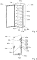
- Fig. 1 shows a home appliance 34a comprising a home appliance device, in a schematic perspective view.
- the home appliance 34a is embodied as a refrigerator.
- the home appliance 34a could further be embodied as any other home appliance deemed advantageous by someone skilled in the art, e.g. a climate cabinet, an ice-box, a freezer, a wine-cooler and/or a refrigerator-freezer combination.
- the home appliance device comprises a housing 10a.
- the housing 10a comprises two side walls 44a.
- the two side walls 44a are arranged opposite one another.
- the housing 10a further comprises a bottom wall 46a, a top wall 48a and a rear wall 50a.
- the home appliance device comprises a home appliance door 36a.
- the housing 10a comprises an inner liner 40a.
- the inner liner 40a delimits a storage space 38a of the home appliance device.
- the storage space 38a is a space inside the home appliance device and is provided for storing victuals.
- the inner liner 40a is at least partly, preferably at least mostly and advantageously entirely made of metal, in particular sheet metal.
- the inner liner and/or the outer liner may be at least partly, preferably at least mostly and advantageously entirely made of plastic, in particular a thermoplastic.
- the housing 10a comprises an outer liner 42a.
- the outer liner 42a delimits the home appliance device to an environment.
- the outer liner 42a is at least partly, preferably at least mostly and advantageously entirely made of metal, in particular sheet metal.
- the inner liner and/or the outer liner may be at least partly, preferably at least mostly and advantageously entirely made of plastic, in particular a thermoplastic.
- the housing 10a comprises a door frame 52a.
- the door frame is at least partly, preferably at least mostly and advantageously entirely made of plastic, in particular a thermoplastic.
- the inner liner and/or the outer liner may be at least partly, preferably at least mostly and advantageously entirely made of plastic, in particular a thermoplastic.
- the door frame 52a is directly connected to the inner liner 40a.
- the door frame 52a is indirectly connected to the outer liner 42a.
- the housing 10a comprises in particular a side element 32a.
- the side element 32a is in particular configured for reducing a heat transfer between the inner liner 40a and the outer liner 42a.
- the side element 32a connects the door frame 52a to the outer liner 42a.
- the side element 32a is at least partly, preferably at least mostly and advantageously entirely made of plastic, in particular thermoplastic.
- the side element 32a is manufactured by means of extrusion, in particular plastic extrusion.
- Figs. 2 and 3 show different cross-sectional views of the side wall 44a of the home appliance device.
- the housing 10a in particular the outer liner 42a, the inner liner 40a, the side element 32a and/or the door frame 52a defines an insulation space 12a.
- the insulation space 12a is configured for reducing a heat transfer from an environment of the home appliance device to the storage space 38a of the home appliance device.
- the insulation space 12a is filled with an insulation means, in particular foam, preferably polymer foam, in particular polyurethane foam.
- the home appliance device comprises a heating unit 14a.
- the heating unit 14a is arranged inside the insulation space 12a.
- the heating unit 14a contacts the housing 10a, in particular the door frame 52a.
- the heating unit 14a is configured for producing heat and is specifically used to prevent further components of the home appliance device, in particular of the home appliance door 36a and/or the housing 10a, in particular the side element 32a, from condensing and/or icing up.
- the heating unit 14a is embodied as a heat pipe.
- the heating unit 14a extends at least substantially parallel to a main extension direction of the housing 10a. Further, the heating unit 14a extends alongside the door frame 52a.
- the home appliance device comprises a heat transfer element 16a.
- the heat transfer element 16a is arranged inside the insulation space 12a.
- the heat transfer element 16a is configured for transferring heat.
- the heat transfer element 16a has a thermal conductivity of at least 10 W/(m ⁇ K).
- the heat transfer element 16a is implemented separately from the housing 10a.
- the heat transfer element 16a is implemented separately from the heating unit 14a.
- the heat transfer element 16a is at least partly made of steel.
- the heat transfer element 16a contacts at least partly the heating unit 14a.
- the heat transfer element 16a contacts at least partly the housing 10a, in particular the side element 32a.
- the heat transfer element 16a transfers heat from the heating unit 14a to the housing 10a, in particular the side element 32a.
- the side element 32a comprises a plurality of protrusions 26a.
- the protrusions 26a protrude towards the insulation space 12a.
- the protrusions 26a each provide a contact area 22a for contacting the heat transfer element 16a.
- the heat transfer element 16a has at least two contact areas 22a with the side element 32a.
- the home appliance device comprises a fixing unit 33a for fixing the heat transfer element 16a to the housing 10a, in particular the side element 32a.
- the fixing unit 33a fixes the heat transfer element 16a to the housing 10a, in particular to the side element 32a, at least in a form-fit manner. Alternatively or additionally the fixing unit fixes the heat transfer element to the housing in a force-fit manner.
- the fixing unit 33a is in particular at least partly implemented integrally with the heat transfer element 16a and at least partly implemented integrally with the housing 10a, in particular the side element 32a.
- the fixing unit 33a comprises a first fixing element 54a.
- the fixing unit 33a comprises a second fixing element 56a.
- the second fixing element 56a contacts the first fixing element 54a.
- the first fixing element 54a and the second fixing element 56a cooperate for fixing the heat transfer element 16a to the housing 10a, in particular to the side element 32a.
- the side element 32a embodies the second fixing element 54a.
- the side element 32a comprises a first section which embodies the second fixing element 54a.
- the second fixing element 54a least partly encompassing the heat transfer element 16a.
- the heat transfer 16a embodies the first fixing element 56a.
- the heat transfer element 16a comprises a second section which at least partly embodies the first fixing element 56a. In particular the second section is at least substantially u-shaped.
- the second section of the heat transfer element 16a encompasses the first section of the side element 32a.
- the heat transfer element 16a has at least one undulation 18a.
- the undulation 18a is at least section-wise at least substantially meander-shaped.
- the undulation 18a has an amplitude 20a.
- the amplitude 20a extends at least substantially perpendicularly to a main extension of the heat transfer element 16a.
- the amplitude 20a extends at least substantially perpendicularly to a main direction of a heat transfer.
- the home appliance device further comprises a supporting element 30a.
- the supporting element 30a supports the housing 10a.
- the supporting element 30a is embodied by the heat transfer element 16a.
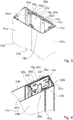
- Fig. 4 shows a further exemplary embodiment of the invention.
- the following description is substantially limited to the differences between the exemplary embodiments, wherein regarding structural elements, features and functions that remain the same, the description of the other exemplary embodiment, in particular the exemplary embodiment of figs. 1 to 3 , may be referred to.
- the letter a of the reference numerals in the exemplary embodiment of fig. 1 to 3 has been substituted by the letter b in the reference numerals of the exemplary embodiment of fig. 4 .
- structural elements having the same denomination in particular regarding structural elements having the same reference numerals, principally the drawing and/or the description of the other exemplary embodiment, in particular of the exemplary embodiment of figs. 1 to 3 , may be referred to.
- Fig. 4 shows a portion of a further home appliance device comprising a heat transfer element 16b.
- the exemplary embodiment of fig. 4 differs from the preceding exemplary embodiment at least substantially by the implementation of the heat transfer element 16b.
- the heat transfer element 16b contacts a heating unit 14b of the home appliance device from a lateral side.
- the heat transfer element 16b further contacts a door frame 52b.
- the heat transfer element 16b contacts the door frame 52b in a vicinity of a contact between the heat transfer element 16b and the heating unit 14b. In a vicinity of the door frame 52b the shape of the heat transfer element 16b is equivalent to a shape of the door frame 52b.
- the heat transfer element 16b comprises at least one embossed element 58b.
- the embossed element 58b is embodied by an undulation 18b of the heat transfer element 16b.
- the undulation 18b may in particular be produced by a stamping and/or bending process.
- the heat transfer element 16b comprises at least one recess 60b in form of an opening or through-hole.
- the heat transfer element 16b comprises four recesses 60b. These recesses 60b allow insulation material to enter a slit-like cavity formed between the side element 32b and the heat transfer element 16b.
- the heat transfer element 16b may comprise a different number of recesses 60b and/or embossed elements 58b, as considered advantageously to someone skilled in the art.
Landscapes
- Engineering & Computer Science (AREA)
- Chemical & Material Sciences (AREA)
- Combustion & Propulsion (AREA)
- Physics & Mathematics (AREA)
- Mechanical Engineering (AREA)
- Thermal Sciences (AREA)
- General Engineering & Computer Science (AREA)
- Refrigerator Housings (AREA)
Abstract
For the purpose of improving an efficiency a home appliance device, in particular a home chiller appliance device, is proposed comprising: a housing (10a) delimiting an insulation space (12a); a heating unit (14a) arranged inside the insulation space (12a); and a heat transfer element (16a) arranged inside the insulation space (12a), the heat transfer element (16a) contacting at least partly the heating unit (14a) and at least partly the housing (10a) for transferring heat from the heating unit (14a) to the housing (10a).
Description
- The invention relates to a home appliance device, in particular a home chiller appliance device, according to claim 1.
-
WO 2007/062909 discloses a home appliance device which comprises a housing delimiting an insulation space, a heating unit arranged inside the insulation space and a supporting element which supports the housing and is arranged inside the insulation space. - An objective of the invention is, in particular, to provide a home appliance device with improved characteristics regarding efficiency. This objective is achieved, according to the invention, by the features of claim 1, while further implementations and further developments of the invention may be gathered from the dependent claims.
- A home appliance device, in particular a home chiller appliance device, is proposed comprising: a housing delimiting an insulation space; a heating unit arranged inside the insulation space; and a heat transfer element which is arranged inside the insulation space and contacts at least partly the heating unit and at least partly the housing for transferring heat from the heating unit to the housing.
- By means of the invention in particular an efficiency of the home appliance device can be improved. Typically by means of the heat transfer element heat from the heating unit can be used to prevent further components of the home appliance device from icing up and/or condensing. As a result, in particular energy efficiency can be improved, as heat can be directed to specific locations at the housing, without affecting an insulation effect.
- In this context, "configured" is in particular to mean specifically programmed, designed and/or equipped. By an object being configured for a certain function is in particular to be understood that the object implements and/or fulfills said certain function in at least one application state and/or operating state. A "home appliance device" is in particular to be understood as a portion, preferably a sub-assembly group, of a home appliance. The home appliance is, in this context, in particular provided for storing and preferably tempering victuals such as beverages, in particular alcoholic beverages such as wine, meat, fish, vegetables, fruits, milk and/or dairy products in at least one operating state, advantageously for the purpose of enhancing a quality and/or a storage life of the stored victuals. For example, the home appliance is embodied as a home chiller appliance, which is in at least one operating state configured for cooling victuals. The home chiller appliance could in particular be embodied as a climate cabinet, an ice-box, a wine-cooler, a freezer and/or a refrigerator-freezer combination. The home chiller appliance may be embodied as a refrigerator. However, the home appliance could also be embodied as a home appliance for warming and in particular for cooking victuals, e.g. an oven, a cooker and/or a microwave.
- The housing comprises in particular an inner liner and an outer liner. The inner liner delimits in particular a storage space of the home appliance device. The storage space is in particular a space inside the home appliance device, which is provided for storing victuals. The outer liner delimits the home appliance device to an environment. The inner liner and/or the outer liner are/is at least partly or at least mostly or entirely made of metal, in particular sheet metal. Alternatively or additionally the inner liner and/or the outer liner may be at least partly or at least mostly or entirely made of plastic, in particular a thermoplastic. The term "at least mostly" with reference to an object is in particular to mean by more than 50 % or by more than 65 % or by more than 80 % or by more than 95 % of an object, in particular a surface area and/or a volume and/or a mass of the object.
- Further the housing comprises a door frame on which, in a closed state of the home appliance door, a home appliance door of the home appliance device may rest in a flat position. In particular, the door frame may preferably be directly connected to the inner liner and/or the outer liner. For example the door frame is at least partly, or at least mostly or entirely made of plastic, e.g. a thermoplastic. Alternatively or additionally the inner liner and/or the outer liner may be at least partly, or at least mostly or entirely made of plastic, e.g. a thermoplastic.
- The housing comprises in particular a side element. The side element is in particular configured for reducing a heat transfer between the inner liner and the outer liner. The side element connects the door frame to the outer liner. The side element is in particular at least partly or at least mostly or entirely made of plastic, e.g. thermoplastic. For example the side element is manufactured by means of extrusion, in particular plastic extrusion.
- In this context, the term "connected" is in particular to mean connected in a form-fit and/or force-fit manner. The term "fixed in a force-fit and/or form-fit manner" is in particular to mean preferably fixed releasably, wherein a holding force between two structural components is preferably transferred via a geometric engagement of the structural components with each other and/or preferably via a friction force acting between the structural components. Alternatively or additionally a connection may be provided by substance-to-substance bond, preferably an adhesive and/or cohesive connection.
- In particular, the inner liner, the side element, the door frame and/or the outer liner together define the insulation space. The insulation space is in particular configured for reducing a heat transfer from an environment of the home appliance device to the storage space of the home appliance device. The insulation space is in particular filled with an insulation means, in particular foam, preferably polymer foam, in particular polyurethane foam.
- In this context, a "heating unit" is in particular to be understood as a unit which is configured for producing heat and which is preferably specifically used to prevent further components of the home appliance device, in particular of the home appliance door and or the housing, in particular the side element, from condensing and/or icing up. In particular, the heating unit may be embodied as a heat pipe and may extend for example at least substantially parallel to a main extension direction of the housing. For example the heating unit extends alongside the door frame. In this context, "at least substantially parallel" is in particular to be understood as an orientation of a direction with respect to a reference direction, in particular in a plane, wherein the direction and the reference direction include an angle of 0°, the orientation in particular having a deviation of less than 15°, advantageously of less than 10° and particularly advantageously of less than 2°.
- In this context, a "heat transfer element" is in particular to be understood as an element which is configured for transferring heat and which comprises in particular a thermal conductivity of at least 10 W/(m·K) or of at least 50 W/(m·K) or of at last 100 W/(m·K) or of at least 200 W/(m·K). The heat transfer element is in particular implemented separately from the housing and/or the heating unit. The heat transfer element is in particular at least partly or at least mostly or entirely made of metal, e.g. iron, steel, aluminum and/or copper. In this context, a "contact" is in particular to be understood as a thermal contact of at least two objects, wherein preferably the thermal contact has a thermal contact conductivity of at least 1 W/(m·K) or of at least 10 W/(m·K) or of at least 50 W/(m·K) or of at least 100 W/(m·K).
- Further, the heat transfer element, in particular a cross section of the heat transfer element, can have at least one or at least two or a plurality of undulation/s. The undulation may for example comprise at least one or at least two or a plurality of, in particular different amplitudes and/or wavelengths. The undulation may at least section-wise at least be substantially meander-shaped. In this context, an undulation being "at least substantially meander-shaped" is in particular to be understood as an undulation which comprises at least two consecutive turns and/or twists. As a result of this, in particular a stability of the heat transfer element can be improved in an efficient manner without the use of additional components.
- For the purpose of further improving stability, it is proposed that the undulation may have an amplitude extending at least substantially perpendicularly to a main extension of the heat transfer element. A "main extension" of an object is, in particular, to be understood as a largest extension of an imaginary rectangular cuboid which only just entirely encloses the object and which preferably extends through a geometric center of the object. In this context, "at least substantially perpendicular" is in particular to mean an orientation of a direction with respect to a reference direction, in particular in a plane, wherein the direction and the reference direction include an angle of 90°, the orientation having in particular a deviation of less than 15°, advantageously of less than 10° and particularly advantageously of less than 2°.
- In a further implementation of the invention it is proposed that the undulation may have an amplitude extending at least substantially perpendicularly to a main direction of a heat transfer. In this context, a "main direction of a heat transfer" is in particular to be understood as a direction of a shortest connecting route of two objects which are connected by means of the heat transfer element, the connecting route preferably comprising the greatest thermal conductivity and/or thermal contact conductivity. As a result of this, in particular homogeneity of the heat transfer can be increased.
- It is also proposed that the heat transfer element may have at least one or at least two contact areas, in particular thermal contact areas, with the housing, in particular with the side element. As a result of this, in particular a heat transfer can be further improved.
- The heat transfer element can have a substantially constant cross-section along its main extension. In this context "substantially" is in particular to be understood as not considering a different cross-section at one end region or both end regions of the heat transfer element, whereas an end region can be specified as 10% of the length of the heat transfer element measured from the respective end. Also "substantially" in this context shall not exclude recesses or openings or through-holes within the heat transfer element. In particular, the undulation or undulations shall be considered as forming the cross-section in this context.
- For the purpose of improving heat transfer, it is proposed that the housing, in particular the side element, may comprise at least one or at least two or a plurality of protrusion/s, which protrude/s into the insulation space and provide/s at least one or at least two or a plurality of contact area/s, in particular the before-mentioned contact areas, for contacting the heat transfer element. The protrusion may have in particular an at least substantially square shaped cross-section.
- In addition, it is proposed that the home appliance device may further comprise a supporting element which supports the housing and which may at least partly or at least mostly or entirely embodied by the heat transfer element. The supporting element comprises in particular a main extension which is at least substantially parallel to a main extension of the housing. As a result of this, in particular a stability of the home appliance device can be improved in a simple manner.
- Furthermore, it is proposed that the home appliance device may further comprise a fixing unit for fixing the heat transfer element to the housing, in particular to the side element. In particular, the fixing unit may fix the heat transfer element to the housing, in particular to the side element, at least in a form-fit manner. Alternatively or additionally the fixing unit may fix the heat transfer element to the housing, in particular to the side element, in a force-fit manner. The fixing unit may in particular be at least partly implemented integrally with the housing, in particular the side element, and/or the heat transfer element. "Implemented integrally" is in particular to mean, in this context, connected at least by substance-to-substance bond, e.g. by a welding process, an adhesive bonding, an injection-molding process and/or by another process that is deemed expedient by a person having ordinary skill in the art. "Implemented integrally" could in particular mean made of one piece. "Made of one piece" is, in particular, to mean, in this context, manufactured from one single piece, e.g. by production from one single cast and/or by manufacturing in a one-component or multi-component injection-molding process, for example from a single blank. The fixing unit comprises in particular a first fixing element and a corresponding second fixing element, which cooperate for fixing the heat transfer element to the housing, for example to the side element. The heat transfer element can comprise a second section which at least partly embodies the first fixing element. The housing, in particular the side element, can comprise a first section which at least partly embodies the second fixing element. The second section can at least be substantially u-shaped. The side element may at least partly encompass the heat transfer element. For example, the first section of the side element may encompass the second section of the heat transfer element. As a result, in particular the heat transfer element can be fixed to the housing in a simple way.
- Herein the home appliance device is not to be limited to the application and implementation described above. In particular, for the purpose of fulfilling a functionality herein described, the home appliance device may comprise a number of respective elements, structural components and units that differs from the number mentioned herein. Furthermore, regarding the value ranges mentioned in this disclosure, values within the limits mentioned are to be understood to be also disclosed and to be used as applicable.
- Further details may become apparent from the following description of the drawing. In the drawing exemplary embodiments of the invention are shown. The drawing, the description and the claims contain a plurality of features in combination. The person having ordinary skill in the art will purposefully also consider the features separately and will find further expedient combinations.
- If there is more than one specimen of a certain object, only one of these is given a reference numeral in the figures and in the description. The description of this specimen may be correspondingly transferred to the other specimens of the object.
-
- Fig. 1
- a home appliance comprising a home appliance device, in a schematic perspective view,
- Fig. 2
- a portion of the home appliance device, comprising a housing, in a cross-sectional top view, and
- Fig. 3
- a portion of the home appliance device, comprising the housing, in a cross-sectional perspective view, and
- Fig. 4.
- a portion of an alternative home appliance device, comprising a housing, in a cross-sectional perspective view.
-
Fig. 1 shows ahome appliance 34a comprising a home appliance device, in a schematic perspective view. Thehome appliance 34a is embodied as a refrigerator. Thehome appliance 34a could further be embodied as any other home appliance deemed advantageous by someone skilled in the art, e.g. a climate cabinet, an ice-box, a freezer, a wine-cooler and/or a refrigerator-freezer combination. - The home appliance device comprises a
housing 10a. Thehousing 10a comprises twoside walls 44a. For the sake of clarity, in the following only oneside wall 44a is given a reference numeral and is described in detail. The following description may be transferred to thefurther side wall 44a accordingly. The twoside walls 44a are arranged opposite one another. Thehousing 10a further comprises abottom wall 46a, atop wall 48a and arear wall 50a. The home appliance device comprises ahome appliance door 36a. - The
housing 10a comprises aninner liner 40a. Theinner liner 40a delimits astorage space 38a of the home appliance device. Thestorage space 38a is a space inside the home appliance device and is provided for storing victuals. Theinner liner 40a is at least partly, preferably at least mostly and advantageously entirely made of metal, in particular sheet metal. Alternatively or additionally the inner liner and/or the outer liner may be at least partly, preferably at least mostly and advantageously entirely made of plastic, in particular a thermoplastic. - The
housing 10a comprises anouter liner 42a. Theouter liner 42a delimits the home appliance device to an environment. Theouter liner 42a is at least partly, preferably at least mostly and advantageously entirely made of metal, in particular sheet metal. Alternatively or additionally the inner liner and/or the outer liner may be at least partly, preferably at least mostly and advantageously entirely made of plastic, in particular a thermoplastic. - Further the
housing 10a comprises adoor frame 52a. In a closed state of thehome appliance door 36a, thehome appliance door 36a rests in a flat position on thedoor frame 52a. Advantageously the door frame is at least partly, preferably at least mostly and advantageously entirely made of plastic, in particular a thermoplastic. Alternatively or additionally the inner liner and/or the outer liner may be at least partly, preferably at least mostly and advantageously entirely made of plastic, in particular a thermoplastic. Thedoor frame 52a is directly connected to theinner liner 40a. Thedoor frame 52a is indirectly connected to theouter liner 42a. - The
housing 10a comprises in particular aside element 32a. Theside element 32a is in particular configured for reducing a heat transfer between theinner liner 40a and theouter liner 42a. Theside element 32a connects thedoor frame 52a to theouter liner 42a. Theside element 32a is at least partly, preferably at least mostly and advantageously entirely made of plastic, in particular thermoplastic. Theside element 32a is manufactured by means of extrusion, in particular plastic extrusion. -
Figs. 2 and3 show different cross-sectional views of theside wall 44a of the home appliance device. Thehousing 10a, in particular theouter liner 42a, theinner liner 40a, theside element 32a and/or thedoor frame 52a defines aninsulation space 12a. Theinsulation space 12a is configured for reducing a heat transfer from an environment of the home appliance device to thestorage space 38a of the home appliance device. Theinsulation space 12a is filled with an insulation means, in particular foam, preferably polymer foam, in particular polyurethane foam. - The home appliance device comprises a
heating unit 14a. Theheating unit 14a is arranged inside theinsulation space 12a. Theheating unit 14a contacts thehousing 10a, in particular thedoor frame 52a. Theheating unit 14a is configured for producing heat and is specifically used to prevent further components of the home appliance device, in particular of thehome appliance door 36a and/or thehousing 10a, in particular theside element 32a, from condensing and/or icing up. Theheating unit 14a is embodied as a heat pipe. Theheating unit 14a extends at least substantially parallel to a main extension direction of thehousing 10a. Further, theheating unit 14a extends alongside thedoor frame 52a. - The home appliance device comprises a
heat transfer element 16a. Theheat transfer element 16a is arranged inside theinsulation space 12a. Theheat transfer element 16a is configured for transferring heat. Theheat transfer element 16a has a thermal conductivity of at least 10 W/(m·K). Theheat transfer element 16a is implemented separately from thehousing 10a. Theheat transfer element 16a is implemented separately from theheating unit 14a. Theheat transfer element 16a is at least partly made of steel. - The
heat transfer element 16a contacts at least partly theheating unit 14a. Theheat transfer element 16a contacts at least partly thehousing 10a, in particular theside element 32a. Theheat transfer element 16a transfers heat from theheating unit 14a to thehousing 10a, in particular theside element 32a. For contacting theheat transfer element 16a, theside element 32a comprises a plurality ofprotrusions 26a. Theprotrusions 26a protrude towards theinsulation space 12a. Theprotrusions 26a each provide acontact area 22a for contacting theheat transfer element 16a. In the present case theheat transfer element 16a has at least twocontact areas 22a with theside element 32a. - The home appliance device comprises a fixing
unit 33a for fixing theheat transfer element 16a to thehousing 10a, in particular theside element 32a. The fixingunit 33a fixes theheat transfer element 16a to thehousing 10a, in particular to theside element 32a, at least in a form-fit manner. Alternatively or additionally the fixing unit fixes the heat transfer element to the housing in a force-fit manner. The fixingunit 33a is in particular at least partly implemented integrally with theheat transfer element 16a and at least partly implemented integrally with thehousing 10a, in particular theside element 32a. The fixingunit 33a comprises afirst fixing element 54a. The fixingunit 33a comprises asecond fixing element 56a. Thesecond fixing element 56a contacts thefirst fixing element 54a. Thefirst fixing element 54a and thesecond fixing element 56a cooperate for fixing theheat transfer element 16a to thehousing 10a, in particular to theside element 32a. - The
side element 32a embodies thesecond fixing element 54a. Theside element 32a comprises a first section which embodies thesecond fixing element 54a. Thesecond fixing element 54a least partly encompassing theheat transfer element 16a. Theheat transfer 16a embodies thefirst fixing element 56a. Theheat transfer element 16a comprises a second section which at least partly embodies thefirst fixing element 56a. In particular the second section is at least substantially u-shaped. The second section of theheat transfer element 16a encompasses the first section of theside element 32a. - The
heat transfer element 16a has at least oneundulation 18a. Theundulation 18a is at least section-wise at least substantially meander-shaped. Theundulation 18a has anamplitude 20a. Theamplitude 20a extends at least substantially perpendicularly to a main extension of theheat transfer element 16a. Theamplitude 20a extends at least substantially perpendicularly to a main direction of a heat transfer. - The home appliance device further comprises a supporting
element 30a. The supportingelement 30a supports thehousing 10a. The supportingelement 30a is embodied by theheat transfer element 16a. -
Fig. 4 shows a further exemplary embodiment of the invention. The following description is substantially limited to the differences between the exemplary embodiments, wherein regarding structural elements, features and functions that remain the same, the description of the other exemplary embodiment, in particular the exemplary embodiment offigs. 1 to 3 , may be referred to. For distinguishing the exemplary embodiments, the letter a of the reference numerals in the exemplary embodiment offig. 1 to 3 has been substituted by the letter b in the reference numerals of the exemplary embodiment offig. 4 . Regarding structural elements having the same denomination, in particular regarding structural elements having the same reference numerals, principally the drawing and/or the description of the other exemplary embodiment, in particular of the exemplary embodiment offigs. 1 to 3 , may be referred to. -
Fig. 4 shows a portion of a further home appliance device comprising aheat transfer element 16b. The exemplary embodiment offig. 4 differs from the preceding exemplary embodiment at least substantially by the implementation of theheat transfer element 16b. Theheat transfer element 16b contacts aheating unit 14b of the home appliance device from a lateral side. Theheat transfer element 16b further contacts adoor frame 52b. Theheat transfer element 16b contacts thedoor frame 52b in a vicinity of a contact between theheat transfer element 16b and theheating unit 14b. In a vicinity of thedoor frame 52b the shape of theheat transfer element 16b is equivalent to a shape of thedoor frame 52b. - Further the
heat transfer element 16b comprises at least oneembossed element 58b. Theembossed element 58b is embodied by anundulation 18b of theheat transfer element 16b. Theundulation 18b may in particular be produced by a stamping and/or bending process. Theheat transfer element 16b comprises at least onerecess 60b in form of an opening or through-hole. In the present case theheat transfer element 16b comprises fourrecesses 60b. Theserecesses 60b allow insulation material to enter a slit-like cavity formed between theside element 32b and theheat transfer element 16b. Alternatively or additionally theheat transfer element 16b may comprise a different number ofrecesses 60b and/orembossed elements 58b, as considered advantageously to someone skilled in the art. - The following is a summary list of reference numerals and the corresponding structure used in the above description of the invention:
- 10a, 10b
- Housing
- 12
- Insulation space
- 14a, 14b
- Heating unit
- 16a, 16b
- Heat transfer element
- 18a, 18b
- Undulation
- 20a, 20b
- Amplitude
- 22a, 22b
- Contact area
- 26a, 26b
- Protrusion
- 30a, 30b
- Supporting element
- 32a, 32b
- Side element
- 33
- Fixing unit
- 34a
- Home appliance
- 36
- Home appliance door
- 38
- Storage space
- 40a, 40b
- Inner liner
- 42a, 42b
- Outer liner
- 44a, 44b
- Side wall
- 46
- Bottom wall
- 48
- Top wall
- 50
- Rear wall
- 52a, 52b
- Door frame
- 54a, 54b
- Second fixing element
- 56a, 56b
- First fixing element
- 58b
- Embossed element
- 60b
- Recess
Claims (12)
- A home appliance device, in particular a home chiller appliance device, comprising:a housing delimiting an insulation space; a heating unit arranged inside the insulation space; and a heat transfer element arranged inside the insulation space, the heat transfer element contacting at least partly the heating unit and at least partly the housing for transferring heat from the heating unit to the housing.
- The home appliance device according to claim 1, the heat transfer element having at least one undulation.
- The home appliance device according to claim 2, the undulation being at least section-wise at least substantially meander-shaped.
- The home appliance device according to claim 3, the undulation having an amplitude extending at least substantially perpendicularly to a main extension of the heat transfer element.
- The home appliance device at least according to claim 2, the undulation having an amplitude extending at least substantially perpendicularly to a main direction of a heat transfer.
- The home appliance device according to claim 1, the heat transfer element having at least one contact area with the housing.
- The home appliance device according to claim 1, the housing comprising at least one protrusion, which protrudes into the insulation space, and providing a contact area for contacting the heat transfer element.
- The home appliance device according to claim 1, the housing being at least partly made of plastic.
- The home appliance device according to claim 1, further comprising a supporting element which supports the housing and which is at least partly embodied by the heat transfer element.
- The home appliance device according to claim 1, further comprising a fixing unit for fixing the heat transfer element to the housing.
- The home appliance device according to claim 1, the housing comprising a side element which at least partly encompasses the heat transfer element.
- A home appliance, in particular a home chiller appliance, comprising at least one home appliance device according to claim 1.
Applications Claiming Priority (1)
| Application Number | Priority Date | Filing Date | Title |
|---|---|---|---|
| US15/359,688 US20180142938A1 (en) | 2016-11-23 | 2016-11-23 | Home Appliance Device |
Publications (1)
| Publication Number | Publication Date |
|---|---|
| EP3327378A1 true EP3327378A1 (en) | 2018-05-30 |
Family
ID=60331478
Family Applications (1)
| Application Number | Title | Priority Date | Filing Date |
|---|---|---|---|
| EP17201980.4A Withdrawn EP3327378A1 (en) | 2016-11-23 | 2017-11-16 | Home appliance device |
Country Status (2)
| Country | Link |
|---|---|
| US (1) | US20180142938A1 (en) |
| EP (1) | EP3327378A1 (en) |
Cited By (1)
| Publication number | Priority date | Publication date | Assignee | Title |
|---|---|---|---|---|
| EP4023980A1 (en) | 2020-12-30 | 2022-07-06 | BSH Hausgeräte GmbH | A household appliance |
Families Citing this family (2)
| Publication number | Priority date | Publication date | Assignee | Title |
|---|---|---|---|---|
| TR202010143A2 (en) * | 2020-06-29 | 2022-01-21 | Bsh Ev Aletleri San Ve Tic As | A HOME APPLIANCE WITH A BODY CONTAINING A SEALING ELEMENT |
| CN115200295B (en) * | 2022-07-15 | 2024-02-20 | 温州市顶诺食品有限公司 | Freezer pan feeding device |
Citations (6)
| Publication number | Priority date | Publication date | Assignee | Title |
|---|---|---|---|---|
| US2632313A (en) * | 1951-03-03 | 1953-03-24 | Gen Motors Corp | Refrigerating apparatus having means for preventing condensation |
| JPS6283175U (en) * | 1985-11-15 | 1987-05-27 | ||
| US4881315A (en) * | 1989-01-18 | 1989-11-21 | General Electric Company | Method of assembling an anti-sweat heater in a refrigerator cabinet |
| US6393855B1 (en) * | 2001-04-24 | 2002-05-28 | Maytag Corporation | Methods and devices for retaining a heating element within a refrigeration cabinet |
| WO2007062909A1 (en) | 2005-11-30 | 2007-06-07 | BSH Bosch und Siemens Hausgeräte GmbH | Refrigeration device comprising an insulation strip for thermally decoupling the lateral walls |
| WO2012028998A2 (en) * | 2010-08-31 | 2012-03-08 | BSH Bosch und Siemens Hausgeräte GmbH | Cooling unit |
Family Cites Families (3)
| Publication number | Priority date | Publication date | Assignee | Title |
|---|---|---|---|---|
| JPS5468562A (en) * | 1977-11-11 | 1979-06-01 | Hitachi Ltd | Refrigerator |
| WO2007018601A1 (en) * | 2005-08-02 | 2007-02-15 | Rubicon Genomics, Inc. | Compositions and methods for processing and amplification of dna, including using multiple enzymes in a single reaction |
| US9970701B2 (en) * | 2014-01-07 | 2018-05-15 | Samsung Electronics Co., Ltd. | Refrigerator having a heating pipe |
-
2016
- 2016-11-23 US US15/359,688 patent/US20180142938A1/en not_active Abandoned
-
2017
- 2017-11-16 EP EP17201980.4A patent/EP3327378A1/en not_active Withdrawn
Patent Citations (6)
| Publication number | Priority date | Publication date | Assignee | Title |
|---|---|---|---|---|
| US2632313A (en) * | 1951-03-03 | 1953-03-24 | Gen Motors Corp | Refrigerating apparatus having means for preventing condensation |
| JPS6283175U (en) * | 1985-11-15 | 1987-05-27 | ||
| US4881315A (en) * | 1989-01-18 | 1989-11-21 | General Electric Company | Method of assembling an anti-sweat heater in a refrigerator cabinet |
| US6393855B1 (en) * | 2001-04-24 | 2002-05-28 | Maytag Corporation | Methods and devices for retaining a heating element within a refrigeration cabinet |
| WO2007062909A1 (en) | 2005-11-30 | 2007-06-07 | BSH Bosch und Siemens Hausgeräte GmbH | Refrigeration device comprising an insulation strip for thermally decoupling the lateral walls |
| WO2012028998A2 (en) * | 2010-08-31 | 2012-03-08 | BSH Bosch und Siemens Hausgeräte GmbH | Cooling unit |
Cited By (2)
| Publication number | Priority date | Publication date | Assignee | Title |
|---|---|---|---|---|
| EP4023980A1 (en) | 2020-12-30 | 2022-07-06 | BSH Hausgeräte GmbH | A household appliance |
| US11740010B2 (en) | 2020-12-30 | 2023-08-29 | Bsh Hausgeraete Gmbh | Household appliance |
Also Published As
| Publication number | Publication date |
|---|---|
| US20180142938A1 (en) | 2018-05-24 |
Similar Documents
| Publication | Publication Date | Title |
|---|---|---|
| EP3327378A1 (en) | Home appliance device | |
| US10386111B2 (en) | Home appliance device and method for assembling a home appliance device | |
| EP3327390A1 (en) | Home appliance device | |
| US10281191B2 (en) | Home appliance door | |
| EP3286510B1 (en) | Construction kit for constructing a home appliance device | |
| US11181313B2 (en) | Domestic appliance | |
| US10012430B2 (en) | Home appliance device | |
| EP3327385A1 (en) | Home appliance device | |
| EP1918664A3 (en) | Refrigerating appliance | |
| WO2018096432A1 (en) | Home appliance device | |
| WO2012028468A3 (en) | Refrigeration device, in particular a domestic refrigeration device | |
| EP3327381B1 (en) | Home appliance door | |
| US20180172330A1 (en) | Household appliance device and method for operating a household appliance device | |
| CN109405396B (en) | Domestic refrigeration appliance device | |
| US11566837B2 (en) | Home appliance device and method for assembling the home appliance device | |
| WO2018009185A1 (en) | Refrigerated compartment air distribution assembly | |
| CN114341577A (en) | Refrigeration appliance device | |
| CN206496548U (en) | Refrigerating appliance with evaporator | |
| EP3343153A1 (en) | Home appliance device | |
| CN203928558U (en) | The refrigerating appliance with condensation water collection container | |
| EP3327389B1 (en) | Home appliance device | |
| US10876784B2 (en) | Home appliance door | |
| US11493264B2 (en) | Home appliance device and method of manufacturing the home appliance device | |
| CN216897959U (en) | Domestic refrigeration appliance device | |
| EP4023980A1 (en) | A household appliance |
Legal Events
| Date | Code | Title | Description |
|---|---|---|---|
| PUAI | Public reference made under article 153(3) epc to a published international application that has entered the european phase |
Free format text: ORIGINAL CODE: 0009012 |
|
| AK | Designated contracting states |
Kind code of ref document: A1 Designated state(s): AL AT BE BG CH CY CZ DE DK EE ES FI FR GB GR HR HU IE IS IT LI LT LU LV MC MK MT NL NO PL PT RO RS SE SI SK SM TR |
|
| AX | Request for extension of the european patent |
Extension state: BA ME |
|
| STAA | Information on the status of an ep patent application or granted ep patent |
Free format text: STATUS: THE APPLICATION IS DEEMED TO BE WITHDRAWN |
|
| 18D | Application deemed to be withdrawn |
Effective date: 20181201 |