EP3323239B1 - Systems and methods for processing recorded data for storage using computer-aided dispatch information - Google Patents
Systems and methods for processing recorded data for storage using computer-aided dispatch information Download PDFInfo
- Publication number
- EP3323239B1 EP3323239B1 EP16825204.7A EP16825204A EP3323239B1 EP 3323239 B1 EP3323239 B1 EP 3323239B1 EP 16825204 A EP16825204 A EP 16825204A EP 3323239 B1 EP3323239 B1 EP 3323239B1
- Authority
- EP
- European Patent Office
- Prior art keywords
- auditable
- event
- data
- video data
- camera
- Prior art date
- Legal status (The legal status is an assumption and is not a legal conclusion. Google has not performed a legal analysis and makes no representation as to the accuracy of the status listed.)
- Active
Links
- 238000000034 method Methods 0.000 title claims description 73
- 238000012545 processing Methods 0.000 title claims description 7
- 238000007726 management method Methods 0.000 claims description 121
- 238000013474 audit trail Methods 0.000 claims description 80
- 230000004044 response Effects 0.000 claims description 16
- 230000009471 action Effects 0.000 description 36
- 238000004891 communication Methods 0.000 description 33
- 238000005516 engineering process Methods 0.000 description 11
- 238000010586 diagram Methods 0.000 description 10
- 230000000694 effects Effects 0.000 description 5
- 230000008901 benefit Effects 0.000 description 4
- 230000008859 change Effects 0.000 description 4
- 230000006855 networking Effects 0.000 description 4
- 238000012546 transfer Methods 0.000 description 4
- 230000005540 biological transmission Effects 0.000 description 3
- 230000000875 corresponding effect Effects 0.000 description 3
- 238000012217 deletion Methods 0.000 description 3
- 230000037430 deletion Effects 0.000 description 3
- 230000007613 environmental effect Effects 0.000 description 2
- 230000008676 import Effects 0.000 description 2
- 230000003993 interaction Effects 0.000 description 2
- 230000002452 interceptive effect Effects 0.000 description 2
- 230000002085 persistent effect Effects 0.000 description 2
- 230000000007 visual effect Effects 0.000 description 2
- 230000004913 activation Effects 0.000 description 1
- 230000000903 blocking effect Effects 0.000 description 1
- 230000001413 cellular effect Effects 0.000 description 1
- 230000000295 complement effect Effects 0.000 description 1
- 230000002596 correlated effect Effects 0.000 description 1
- 238000010304 firing Methods 0.000 description 1
- 230000006870 function Effects 0.000 description 1
- 238000013021 overheating Methods 0.000 description 1
- 230000008569 process Effects 0.000 description 1
- 238000010079 rubber tapping Methods 0.000 description 1
- 239000004065 semiconductor Substances 0.000 description 1
- 239000007787 solid Substances 0.000 description 1
- 230000001960 triggered effect Effects 0.000 description 1
Images


Classifications
-
- H—ELECTRICITY
- H04—ELECTRIC COMMUNICATION TECHNIQUE
- H04N—PICTORIAL COMMUNICATION, e.g. TELEVISION
- H04N7/00—Television systems
- H04N7/18—Closed-circuit television [CCTV] systems, i.e. systems in which the video signal is not broadcast
- H04N7/181—Closed-circuit television [CCTV] systems, i.e. systems in which the video signal is not broadcast for receiving images from a plurality of remote sources
-
- G—PHYSICS
- G06—COMPUTING; CALCULATING OR COUNTING
- G06Q—INFORMATION AND COMMUNICATION TECHNOLOGY [ICT] SPECIALLY ADAPTED FOR ADMINISTRATIVE, COMMERCIAL, FINANCIAL, MANAGERIAL OR SUPERVISORY PURPOSES; SYSTEMS OR METHODS SPECIALLY ADAPTED FOR ADMINISTRATIVE, COMMERCIAL, FINANCIAL, MANAGERIAL OR SUPERVISORY PURPOSES, NOT OTHERWISE PROVIDED FOR
- G06Q50/00—Systems or methods specially adapted for specific business sectors, e.g. utilities or tourism
- G06Q50/10—Services
- G06Q50/26—Government or public services
- G06Q50/265—Personal security, identity or safety
-
- H—ELECTRICITY
- H04—ELECTRIC COMMUNICATION TECHNIQUE
- H04N—PICTORIAL COMMUNICATION, e.g. TELEVISION
- H04N5/00—Details of television systems
- H04N5/76—Television signal recording
- H04N5/765—Interface circuits between an apparatus for recording and another apparatus
- H04N5/77—Interface circuits between an apparatus for recording and another apparatus between a recording apparatus and a television camera
-
- H—ELECTRICITY
- H04—ELECTRIC COMMUNICATION TECHNIQUE
- H04N—PICTORIAL COMMUNICATION, e.g. TELEVISION
- H04N7/00—Television systems
- H04N7/18—Closed-circuit television [CCTV] systems, i.e. systems in which the video signal is not broadcast
- H04N7/183—Closed-circuit television [CCTV] systems, i.e. systems in which the video signal is not broadcast for receiving images from a single remote source
- H04N7/185—Closed-circuit television [CCTV] systems, i.e. systems in which the video signal is not broadcast for receiving images from a single remote source from a mobile camera, e.g. for remote control
-
- H—ELECTRICITY
- H04—ELECTRIC COMMUNICATION TECHNIQUE
- H04N—PICTORIAL COMMUNICATION, e.g. TELEVISION
- H04N9/00—Details of colour television systems
- H04N9/79—Processing of colour television signals in connection with recording
- H04N9/80—Transformation of the television signal for recording, e.g. modulation, frequency changing; Inverse transformation for playback
- H04N9/802—Transformation of the television signal for recording, e.g. modulation, frequency changing; Inverse transformation for playback involving processing of the sound signal
-
- G—PHYSICS
- G07—CHECKING-DEVICES
- G07C—TIME OR ATTENDANCE REGISTERS; REGISTERING OR INDICATING THE WORKING OF MACHINES; GENERATING RANDOM NUMBERS; VOTING OR LOTTERY APPARATUS; ARRANGEMENTS, SYSTEMS OR APPARATUS FOR CHECKING NOT PROVIDED FOR ELSEWHERE
- G07C5/00—Registering or indicating the working of vehicles
- G07C5/08—Registering or indicating performance data other than driving, working, idle, or waiting time, with or without registering driving, working, idle or waiting time
- G07C5/0841—Registering performance data
- G07C5/085—Registering performance data using electronic data carriers
- G07C5/0866—Registering performance data using electronic data carriers the electronic data carrier being a digital video recorder in combination with video camera
Landscapes
- Engineering & Computer Science (AREA)
- Business, Economics & Management (AREA)
- Multimedia (AREA)
- Signal Processing (AREA)
- Tourism & Hospitality (AREA)
- General Health & Medical Sciences (AREA)
- Marketing (AREA)
- Development Economics (AREA)
- Health & Medical Sciences (AREA)
- Economics (AREA)
- Computer Security & Cryptography (AREA)
- Human Resources & Organizations (AREA)
- Educational Administration (AREA)
- Primary Health Care (AREA)
- Strategic Management (AREA)
- Physics & Mathematics (AREA)
- General Business, Economics & Management (AREA)
- General Physics & Mathematics (AREA)
- Theoretical Computer Science (AREA)
- Management, Administration, Business Operations System, And Electronic Commerce (AREA)
- Television Signal Processing For Recording (AREA)
Description
- Existing systems for collecting digital video data from wearable cameras have a plethora of technical shortcomings, especially when used in a law enforcement context. Wearable cameras for law enforcement require long battery life to last through an entire shift. However, it is also desirable to monitor the activities performed with such cameras in order to ensure that a chain of custody of any videos recorded by the cameras can be provably established, and to ensure that any videos recorded by the cameras are eventually uploaded to an evidence management system for storage. Because the cameras require minimal power consumption and have only intermittent connectivity to an evidence management system (if any at all), technical hurdles exist in collecting data from wearable cameras in a way that can provide reliable chain-of-custody information and preserve battery life at the same time. Document
EP 2 109 074 A1 describes an incident reporting system comprising cameras. - This summary is provided to introduce a selection of concepts in a simplified form that are further described below in the Detailed Description. This summary is not intended to identify key features of the claimed subject matter, nor is it intended to be used as an aid in determining the scope of the claimed subject matter.
- In some embodiments, a computer-implemented method of processing recorded data for storage is provided. An auditable device stores a set of recorded data within a data store of the auditable device The auditable device receives information from a computer-aided dispatch system indicating at least one event, wherein the at least one event includes an event start time and an event stop time. The auditable device marks at least one subset of the set of recorded data based on the at least one event received from the computer-aided dispatch system. The auditable device uploads the marked at least one subset of the set of recorded data to an evidence management system, wherein the marked at least one subset of the set of recorded data is less than all of the set of recorded data.
- In some embodiments, an auditable camera is provided. The auditable camera includes a video sensor, a video data store, an audit trail data store, and an audit trail gathering engine. The video data store is configured to store video data generated by the video sensor. The audit trail data store is configured to store a set of auditable event entries. The audit trail gathering engine is configured to, in response to receiving a notification of an event reported by a component of the auditable camera, record an auditable event entry representing the event in the audit trail data store. The auditable camera is configured to transmit a subset of the video data stored in the video data store to an evidence management server, wherein the subset of the video data is selected based on the auditable event entry.
- In some embodiments, a non-transitory computer-readable medium having computer-executable instructions stored thereon is provided. The instructions, in response to execution by one or more processors of an auditable device, cause the auditable device to perform actions for processing recorded data for storage that comprise storing a set of recorded data within a data store of the auditable device; receiving information from a computer-aided dispatch system indicating at least one event, wherein the at least one event includes an event start time and an event stop time; marking at least one subset of the set of recorded data based on the at least one event received from the computer-aided dispatch system; and uploading the marked at least one subset of the set of recorded data to an evidence management system, wherein the marked at least one subset of the set of recorded data is less than all of the set of recorded data.
- The foregoing aspects and many of the attendant advantages of this invention will become more readily appreciated as the same become better understood by reference to the following detailed description, when taken in conjunction with the accompanying drawings, wherein:
-
FIGURE 1 is a high-level schematic diagram that illustrates communication between various components of an exemplary embodiment of a system according to various aspects of the present disclosure; -
FIGURE 2 is a block diagram that illustrates components of an exemplary embodiment of an auditable camera according to various aspects of the present disclosure; -
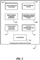
FIGURE 3 is a block diagram that illustrates an exemplary embodiment of a coordinator computing device according to various aspects of the present disclosure; -
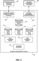
FIGURE 4 is a block diagram that illustrates an exemplary embodiment of an evidence management system according to various aspects of the present disclosure; -
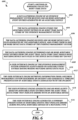
FIGURES 5A-5B are a flowchart that illustrates an exemplary embodiment of a method of auditing camera activity according to various aspects of the present disclosure; -
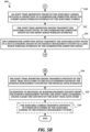
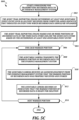
FIGURE 5C is a flowchart that illustrates an exemplary embodiment of a procedure for transmitting recorded data to an evidence management system according to various aspects of the present disclosure; -
FIGURE 6 is a flowchart that illustrates an exemplary embodiment of a method of managing collected audit trail data according to various aspects of the present disclosure; and -
FIGURE 7 is a block diagram that illustrates aspects of anexemplary computing device 700 appropriate for use as a computing device of the present disclosure. - Embodiments of the present disclosure solve the technical problems introduced above, as well as others. In some embodiments, auditable devices such as auditable cameras are provided. The auditable devices maintain audit trail data that is digitally signed and stored on the devices until it can be uploaded to an evidence management system. When an intermittent data connection to the evidence management system is available, the auditable devices transmit records of urgent events to the evidence management system, so that the evidence management system is notified to expect further data associated with the events despite the lack of persistent data connectivity to the device. By using these and other techniques, the technical problems introduced above and others can be overcome.
-
FIGURE 1 is a high-level schematic diagram that illustrates communication between various components of an exemplary embodiment of a system according to various aspects of the present disclosure. In some embodiments, thesystem 100 is configured to allow for collection of auditing information from a plurality of auditable devices. The auditing information is generated by the auditable devices while they are being operated, and is gathered by anevidence management system 102. - In general, a
user 92, such as a law enforcement officer, may carry one or more auditable devices. The devices may include, but are not limited to, anauditable camera 106, anauditable weapon 108, and alight bar sensor 110. Theauditable camera 106 may be, for example, a wearable camera that records video and/or audio data when activated, and stores a record of auditable events that occur (such as the start of recording, the end of recording, various device faults, and/or the like and as described further below). Theauditable weapon 108 may be, for example, a conducted energy weapon (CEW) that records firing events, cartridge loading, holster removal, and/or the like. Thelight bar sensor 110 may detect activation of the light bar on thevehicle 94, which is usually associated with an emergency situation. Other auditable devices, such as a dashboard camera, a heart rate sensor, may also be included in thesystem 100 but are not illustrated inFIGURE 1 . - In some embodiments, the auditable devices may have limited communication functionality. For example, auditable devices may only be able to transmit information to the
evidence management system 102 when physically connected to anevidence collection dock 104 that communicates with theevidence management system 102 via abroadband network 90 such as a LAN, a WAN, and/or the Internet. Accordingly, technical problems arise when attempting to obtain verifiably complete auditing information in that there is no reliable, always-on communication path between theevidence management system 102 and the auditable devices. - In some embodiments, an ad-hoc communication path may be created between the auditable device and the
evidence management system 102 via acoordinator computing device 107. Thecoordinator computing device 107 is illustrated as a smartphone computing device, but in some embodiments may be a laptop computing device, a tablet computing device, or any other suitable computing device capable of being carried by theuser 92 or avehicle 94 associated with theuser 92 and capable of performing the actions described herein. Thecoordinator computing device 107 communicates with the auditable devices, and may also communicate with other devices such as alight bar sensor 110 of avehicle 94 associated with theuser 92, using a short-range wireless communication technology such as Bluetooth, Bluetooth low energy, Zigbee, IrDA, ANT, ANT+, 802.15.4, near-field communication (NFC), a radio frequency identifier (RFID) tag, and/or the like. In some embodiments, theauditable camera 106 may receive data directly from other auditable devices such as anauditable weapon 108 or alight bar sensor 110 in order to enhance the auditable event entries collected by theauditable camera 106. - The
coordinator computing device 107 is capable of communicating with theevidence management system 102, though the communication path between thecoordinator computing device 107 may be unreliable, may drain battery performance too greatly to be constantly enabled, or may be of relatively low bandwidth. As such, the communication of information from thecoordinator computing device 107 to theevidence management system 102 may be sporadic and may transmit only a subset of information gathered by or audited on the auditable devices. Though a singlecoordinator computing device 107 is illustrated, in some embodiments more than onecoordinator computing device 107 may be associated with avehicle 94. For example, a smartphone carried by theuser 92 may be a firstcoordinator computing device 107, and a mobile data terminal (MDT) or mobile digital computer (MDC) mounted in thevehicle 94 may be a secondcoordinator computing device 107. - In some embodiments, auditable devices (such as the
auditable camera 106 and the auditable weapon 108) and/orcoordinator computing devices 107 may also communicate with a computer-aided dispatch (CAD)system 101. TheCAD system 101 may communicate with the auditable devices and/orcoordinator computing devices 107 using any suitable technique, including but not limited to internet data communication over 3G, 4G, LTE, or a similar long-range wireless protocol; short message service (SMS) messages, selective calling, or any other suitable technique. TheCAD system 101 may communicate directly with the auditable devices or may communicate with the auditable devices via thecoordinator computing device 107. - Further aspects of these devices and their capabilities will be discussed below.
-
FIGURE 2 is a block diagram that illustrates components of an exemplary embodiment of an auditable camera according to various aspects of the present disclosure. In some embodiments, theauditable camera 106 is a wearable camera that provides a point of view associated with theuser 92. In some embodiments, theauditable camera 106 may be attached to another device carried by theuser 92, such as a weapon. - As with any camera, the
auditable camera 106 includes at least avideo sensor 202, and may also include anaudio sensor 206. Data collected by thevideo sensor 202 and theaudio sensor 206 may be stored in avideo data store 222 and anaudio data store 224, respectively, though in some embodiments the audio and video information is stored together in a single data store and/or in a combined data file. One example of an appropriate video sensor is a charge-coupled device (CCD), though any other digital image sensor, such as a complementary metal-oxide-semiconductor (CMOS) sensor, an active pixel sensor, or any other type of digital image sensor could be used instead. Any type of microphone may be used as anaudio sensor 206. - As understood by one of ordinary skill in the art, a "data store" as described herein may be any suitable device configured to store data for access by a computing device. One example of a data store suitable for use with the high capacity needs of the
evidence management system 102 is a highly reliable, high-speed relational database management system (RDBMS) executing on one or more computing devices and accessible over a high-speed network. However, any other suitable storage technique and/or device capable of quickly and reliably providing the stored data in response to queries may be used, such as a key-value store, an object database, and/or the like. Further, for theevidence management system 102, the computing device providing the data store may be accessible locally instead of over a network, or may be provided as a cloud-based service. A data store may also include data stored in an organized manner on a computer-readable storage medium, as described further below. One example of a data store suitable for use with the needs of theauditable camera 106 and thecoordinator computing device 107, which includes reliable storage but also low overhead, is a file system or database management system that stores data in files (or records) on a computer readable medium such as flash memory, random access memory (RAM), hard disk drives, and/or the like. One of ordinary skill in the art will recognize that separate data stores described herein may be combined into a single data store, and/or a single data store described herein may be separated into multiple data stores, without departing from the scope of the present disclosure. - The
auditable camera 106 includes a set of engines, including acamera control engine 204, an audittrail signing engine 210, an audittrail gathering engine 214, and an audittrail reporting engine 212. In general, the term "engine" as used herein refers to logic embodied in hardware or software instructions, which can be written in a programming language, such as C, C++, COBOL, JAVA™, PHP, Perl, HTML, CSS, JavaScript, VBScript, ASPX, Microsoft .NET™ languages such as C#, and/or the like. An engine may be compiled into executable programs or written in interpreted programming languages. Engines may be callable from other engines or from themselves. Generally, the engines described herein refer to logical modules that can be merged with other engines or applications, or can be divided into sub-engines. The engines can be stored in any type of computer readable medium or computer storage device and be stored on and executed by one or more general purpose computers, thus creating a special purpose computer configured to provide the engine. Accordingly, the devices and systems illustrated herein include one or more computing devices configured to provide the illustrated engines, though the computing devices themselves have not been illustrated in every case for the sake of clarity. - The
camera control engine 204 is configured to cause theauditable camera 106 to perform camera functions. For example, thecamera control engine 204 may cause thevideo sensor 202 andaudio sensor 206 to begin obtaining data, and may save the video and/or audio data in avideo data store 222 and/oraudio data store 224 after receiving it from the sensor. Thecamera control engine 204 may receive commands to start, pause, or stop the video recording from a physicaluser interface device 208, or may automatically start, pause, or stop the video recording in response to a signal received from some other component of the auditable camera 106 (such as thebattery sensor 234, theclock 230, themotion sensor 238, the short-range wireless interface 228, and/or the like). Thecamera control engine 204 may also change settings on thevideo sensor 202 and/oraudio sensor 206, such as an image quality, a white balance setting, a gain, and/or any other common video or audio recording setting, based on configuration settings received via a physicaluser interface device 208, via the short-range wireless interface 228, via the physical dock interface 232, or by any other suitable technique. Any type of physicaluser interface device 208 that can transmit commands to thecamera control engine 204 may be used, including but not limited to push button switches, toggle switches, slide switches, touch switches, and/or the like. - In some embodiments, the
camera control engine 204 may report starting, pausing, or stopping the video recording, as well as the settings for thevideo sensor 202 andaudio sensor 206, as auditable events to the audittrail gathering engine 214. In some embodiments, thecamera control engine 204 may embed the sensor configuration information in the data stored in thevideo data store 222 and/oraudio data store 224, along with other information about the state of theauditable camera 106 or other information received via the short-range wireless interface about other auditable devices, to prevent the additional information from being disassociated with the video and/or audio data. - The
auditable camera 106 also includes an audit trail data store 216 for storing records of auditable events and acertificate data store 218 for storing data usable for digital signing. The audittrail gathering engine 214 is configured to receive reports of auditable events from the other components of theauditable camera 106, and to record auditable event records that represent the events in the audit trail data store 216. The audittrail signing engine 210 is configured to use one or more signing certificates from thecertificate data store 218 to apply a digital signature to the auditable event records in the audit trail data store 216. The audittrail reporting engine 212 is configured to transmit the audit trail information from the audit trail data store 216 to theevidence management system 102, either directly via the long-range wireless interface 226 or physical dock interface 232, or via the short-range wireless interface 228 and thecoordinator computing device 107. Further details of the functionality of these components are provided below. - The
auditable camera 106 also includes a number of general components, including aclock 230, amotion sensor 238, a physical dock interface 232, abattery sensor 234, abattery 236. Theclock 230 may be used by the audittrail gathering engine 214, the audittrail reporting engine 212, thecamera control engine 204, or any other component of theauditable camera 106 to include timestamp information in generated data. Themotion sensor 238, such as a multi-axis accelerometer, also produces information that may be used by other components. For example, the audittrail gathering engine 214 may use themotion sensor 238 to detect a certain type of motion, such as running, falling, and/or the like, and to treat the detected motion as an auditable event. - The physical dock interface 232 is configured to mate with a physical connector on the
evidence collection dock 104. In some embodiments, the physical dock interface 232 may include a female 2.5mm socket, which mates with a male 2.5mm plug of theevidence collection dock 104. Once docked, theauditable camera 106 may then transfer data to theevidence management system 102 via the connection using any suitable data transmission protocol. In some embodiments, power may be transferred to theauditable camera 106 via the physical dock interface 232 instead of or in addition to the data transfer. In some embodiments, other connection hardware that can provide both power and data connectivity may be used, such as a USB connector, a Firewire connector, and/or the like. - The
battery sensor 234 and thebattery 236 are an example of an internal system that may generate auditable events that are captured by the audittrail gathering engine 214 without user intervention. For example, thebattery sensor 234 may detect a low battery state, a battery overheating state, and/or the like, and may generate alerts to be logged as auditable events by the audit trail gathering engine. Other well-known internal device systems, such as a file system controller, a free-fall sensor, and/or the like, may similarly generate alerts to be logged as auditable events, but are not illustrated here. - The
auditable camera 106 also includes an optional long-range wireless interface 226 and an optional short-range wireless interface 228. The long-range wireless interface 226 may use any suitable networking technology capable of establishing a wireless data connection to the evidence management system 102 (or other computing devices accessible via thenetwork 90, such as the computer-aideddispatch system 402 or the records management system 404) from theauditable camera 106 from any geographical area, including but not limited to 3G, 4G, LTE, and/or the like. The short-range wireless interface 228 may use any suitable wireless networking technology capable of establishing a wireless data connection to thecoordinator computing device 107 when within range of thecoordinator computing device 107, including but not limited to Bluetooth, Bluetooth low energy, ZigBee, NFC, and/or the like. These wireless interfaces are illustrated as optional, because some embodiments may be missing one or both interfaces. For example, in some embodiments, the only communication performed by theauditable camera 106 may be through the physical dock interface 232. As another example, in some embodiments only the short-range wireless interface 228 may be present, and so theauditable camera 106 may only be able to communicate with theevidence management system 102 via the physical dock interface 232 or via the short-range wireless interface 228 through thecoordinator computing device 107. - In some embodiments, actions by the
auditable camera 106 trigger action reporting to one or more computing devices besides theevidence management system 102. In one example, where theuser 92 is a responder (e.g., police officer), actions by theauditable camera 106 trigger reporting action reporting to a computing device associated with a supervisor of theuser 92 and/or a computing device associated with another responder associated with the user 92 (e.g., a partner of user 92). Actions that may trigger action reporting include starting, pausing, or stopping video recording. Other actions that may trigger action reporting may include the manner in which actions by theauditable camera 106, such as manually starting video recording by theuser 92, automatic starting video recording by a remote computing device (e.g., a dispatch computing device), and the like. - When action reporting is triggered, the
auditable camera 106 sends a signal to the one or more computing devices. The signal sent fromauditable camera 106 can be sent via thenetwork 90 to the one or more computing devices, via thecoordinator computing device 107 and thenetwork 90 to the one or more computing devices, via theevidence collection dock 104 and thenetwork 90 to the one or more computing devices, or to the one or more computing devices via any other communication path. The signal may be in the form a text message, an email message, a signal that causes an audible or visual alert, and the like. - Action reporting may be used as an alert to other users associated with the
user 92. In one example, theuser 92 is a responder and theauditable camera 106 is configured to send an action report to a computing device of a supervisor of theuser 92 in response to theauditable camera 106 pausing video recording. This allows the supervisor to know that a recording was paused and possibly investigate why the recording was paused. In this example, theauditable camera 106 may not be configured to send an action report to the computing device of the supervisor in response to theauditable camera 106 starting or stopping video recording as such starting or stopping video recording may occur too frequently for the supervisor to want alerts. In another example, theuser 92 is a responder and theauditable camera 106 is configured to send an action report to a computing device of another responder associated with theuser 92 in response to a video recording of theauditable camera 106 being manually started. Manual starting of the video recording may indicate that a situation of interest is occurring around theuser 92 and action reporting in response to manual starting may be an alert to the other responder to be aware of the situation. - Though
FIGURE 2 illustrates components of a camera, one of ordinary skill in the art will recognize that, other than the components that make the device a camera such as thevideo sensor 202,audio sensor 206, and the associated data stores, similar components may be included in anauditable weapon 108 or an auditable device of some other type. -
FIGURE 3 is a block diagram that illustrates an exemplary embodiment of a coordinator computing device according to various aspects of the present disclosure. As illustrated, thecoordinator computing device 107, which as stated above may be a smart phone or any other suitable computing device, includes a short-range wireless interface 306, a long-range wireless interface 310, and aGPS sensor 314. The short-range wireless interface 306 is configured to allow the components of thecoordinator computing device 107 to communicate with the other nearby components of thesystem 100 when they are within range, including auditable devices such as theauditable camera 106 and theauditable weapon 108 and thelight bar sensor 110 of thevehicle 94. The short-range wireless interface 306 may use one or more short-range wireless networking technologies such as those discussed above with respect to theauditable camera 106 in order to provide these communication paths. The long-range wireless interface 310 is configured to allow thecoordinator computing device 107 to communicate data with theevidence management system 102 as long as thecoordinator computing device 107 is within a service area of a corresponding long-range wireless data service, such as 3G, 4G, LTE, and/or the like. TheGPS sensor 314 is configured to obtain a geographic position of thecoordinator computing device 107 using satellite signals, triangulation of cellular phone towers, or any other technique known to one of ordinary skill in the art. - The
coordinator computing device 107 also includes one or moreuser interface devices 302, auser interface engine 304, an auditabledevice communication engine 308, and asystem communication engine 312. The one or moreuser interface devices 302 may include, but are not limited to, physical buttons, status lights, a display, a touch-screen display, a loudspeaker, and/or the like. Theuser interface engine 304 is configured to present an interactive interface to theuser 92 and receive input from theuser 92 via theuser interface devices 302. The interactive interface may allow theuser 92 to control the auditable devices, add information to auditable events, generate auditable events, manually initiate an upload of urgent auditable events to theevidence management system 102, and/or take other actions within thesystem 100. The auditabledevice communication engine 308 manages communication with the auditable devices via the short-range wireless interface 306, and thesystem communication engine 312 manages communication with theevidence management system 102. Further details of the functionality of the components of thecoordinator computing device 107 are provided below. -
FIGURE 4 is a block diagram that illustrates an exemplary embodiment of an evidence management system according to various aspects of the present disclosure. In some embodiments, theevidence management system 102 comprises a plurality of computing devices configured to provide the illustrated components, though they are described as a single system for clarity. One of ordinary skill in the art will recognize that any suitable server system, such as a single server, a server farm, a cloud service, and/or the like, may be used to provide the functionality of theevidence management system 102. - As illustrated, the
evidence management system 102 includes a computer-aideddispatch system interface 406, a recordsmanagement system interface 408, and anetwork interface 422. The computer-aideddispatch system interface 406 enables theevidence management system 102 to communicate with one or more computer-aided dispatch (CAD)systems 402 operated by other parties. This communication allows theevidence management system 102 to automatically import information from theCAD systems 402, such as incident codes,user 92 orvehicle 94 locations at given times, event start and/or stop information, and/or the like. This information may then be correlated with or otherwise used to enhance information received from auditable devices. For example, the event start and/or stop information could be used by theevidence management system 102 to determine which portions of a larger set of recorded data are important and should be retrieved and saved in a data store of theevidence management system 102. Such examples are discussed further below. In some embodiments, theevidence management system 102 may retrieve information from theCAD system 402 and transmit it to one or more auditable devices. - The records
management system interface 408 enables theevidence management system 102 to communicate with one or morerecords management systems 404 operated by other parties. This communication likewise allows theevidence management system 102 to automatically import information such as case numbers and/or the like. The recordsmanagement system interface 408 may also provide information from theevidence management system 102 back to therecords management systems 404, including but not limited to links to data stored in thevideo data store 412, theaudio data store 414, and/or the audittrail data store 416; copies of audit trail information stored in the audittrail data store 416; and/or the like. As with the connections to the CAD system(s) 402, information from therecords management system 404 could be used to indicate which portions of a larger set of recorded are to be retrieved and saved in a data store of theevidence management system 102, and information from therecords management system 404 could be transmitted by theevidence management system 102 to one or more auditable devices. - The
evidence management system 102 also includes an auditabledevice data store 410, avideo data store 412, anaudio data store 414, and an audittrail data store 416. The auditabledevice data store 410 may be configured to store information associated with each of the auditable devices of thesystem 100. For example, for a givenauditable camera 106, the auditabledevice data store 410 may store information such as a unique device identifier, an identifier (such as a badge number or the like) of auser 92 associated with theauditable camera 106 at a given time or date, capabilities of theauditable camera 106, and/or the like. Thevideo data store 412 andaudio data store 414 are configured to store data captured by one or moreauditable cameras 106 or other devices that can capture audio and/or video data and are enrolled with thesystem 100. In some embodiments, thevideo data store 412 andaudio data store 414 are merged into a single data store, and audio and video data that are recorded contemporaneously may be stored together in a single file. The audittrail data store 416 stores records of auditable events detected by the auditable devices of thesystem 100, as described further below. - The
evidence management system 102 also includes adata gathering engine 418 and auser interface engine 420. Thedata gathering engine 418 is configured to receive audit trail information, video data, audio data, and/or other recorded data from the auditable devices via theevidence collection dock 104 and thecoordinator computing device 107. Theuser interface engine 420 is configured to generate and present user interfaces for displaying and interacting with the data collected by theevidence management system 102 via web pages, application programming interfaces, or any other suitable technology. Each of the interfaces and engines of theevidence management system 102 is configured to use anetwork interface 422 for communication with other components of thesystem 100 via the Internet. Further description of the actions taken by the components of theevidence management system 102 is provided below. -
FIGURES 5A-5B are a flowchart that illustrates an exemplary embodiment of a method of auditing camera activity according to various aspects of the present disclosure. One of ordinary skill in the art will recognize that, although a method of auditing camera activity is illustrated and described, other devices that detect events (such as theauditable weapon 108, thelight bar sensor 110, and/or the like) could also be audited using a similar method, though for such devices the actions relating to transfer of video and/or audio data may not be performed. - From a start block, the
method 500 proceeds to block 502, where an audittrail gathering engine 214 of anauditable camera 106 detects a disconnection of theauditable camera 106 from a physical dock interface 232. In some embodiments, when the physical dock interface 232 is electrically disconnected from theevidence collection dock 104, the physical dock interface 232 transmits a signal to the audittrail gathering engine 214 to notify it of the disconnection event. Next, atblock 504, the audittrail gathering engine 214 creates an auditable event entry in an audit trail data store 216 of theauditable camera 106 indicating that theauditable camera 106 has been undocked. - In some embodiments, particularly where the
user 92 is a law enforcement official, the undocking auditable event entry may indicate the start of a shift and the related start of auditing activities related to that shift. In some embodiments, the audit trail data store 216 may have been emptied after the previously recorded information was transmitted to the evidence management system 102 (as described further below), so at this point, the auditable event entry indicating the start of shift may be the only auditable event entry in the audit trail data store 216. - The
method 500 then proceeds to block 508, where the audittrail gathering engine 214 receives a signal indicating an auditable event. The signal may be received from another component of theauditable camera 106, such as thecamera control engine 204, thebattery sensor 234, a physicaluser interface device 208, the physical dock interface 232, or any other component. The signal may indicate any of a wide variety of auditable events. These events include, but are not limited to: a start recording event, a stop recording event, a pause recording event, a button press event, a battery or other hardware fault, a battery charge status threshold event, a storage error, a free storage threshold event, an interaction or connection status change via a wireless interface, an interaction or connection status change via the physical dock interface 232, a physical motion event, a lack-of-physical motion event (i.e., theauditable camera 106 has remained stationary for a given amount of time, an environmental event such as a change in environmental temperature or humidity past a threshold value, a geofence event, a drop event, and a debug event. - At
block 510, the audittrail gathering engine 214 creates an auditable event entry in the audit trail data store 216. In some embodiments, the auditable event entry includes information that identifies the type of the event (such as a numeric event type identifier, an event type string, and/or the like), and may include further information associated with the event. As several non-limiting examples, a hardware fault auditable event entry may include a fault type and a fault code; a start recording event may include camera settings such as exposure, F-stop, frame rate, and/or the like; a battery fault event may also indicate the type of battery fault; and so on. In some embodiments, the audittrail gathering engine 214 may actively obtain other information to include in the auditable event entry that cannot be derived solely from information included in the signal. As several non-limiting examples, the audittrail gathering engine 214 may itself obtain a timestamp from theclock 230 to be included in the auditable event entry; the audittrail gathering engine 214 may use the short-range wireless interface 228 to obtain GPS information or user-entered metadata from thecoordinator computing device 107 to be included in the auditable event entry; and so on. - At
optional block 512, data associated with the event obtained by one or more sensors of theauditable camera 106 is stored in one ormore data stores auditable camera 106 and is associated with the auditable event entry. For example, if the event is a start recording event, then data obtained by thecamera control engine 204 from thevideo sensor 202 may be stored in thevideo data store 222, and/or data obtained by thecamera control engine 204 from theaudio sensor 206 may be stored in theaudio data store 224. To associate the stored data with the auditable event entry, a unique identifier of the auditable event entry may be stored along with the video or audio data, and/or a unique identifier of the video and/or audio data may be stored in the auditable event entry. The actions described with respect to block 512 are optional because some events, like battery faults, may not be related to the recording of data to be stored in one of thedata stores overall method 500. - Data such as video and/or audio data is recorded continuously by the
auditable camera 106. The auditable event entries may then be associated with or otherwise used to identify subsets of interest within the recorded data. - At
block 514, an audittrail signing engine 210 of theauditable camera 106 applies a digital signature to the auditable event entry. In some embodiments, applying the digital signature uses a cryptographic hash to guarantee that the auditable event entry has not been altered or corrupted since being signed. For example, in one non-limiting embodiment, theevidence management system 102 may assign a private key to theauditable camera 106, which is stored in thecertificate data store 218 when theauditable camera 106 is connected via the physical dock interface 232. The private key is used by the audittrail signing engine 210 to create a cryptographic hash of the auditable event entry, which is then added to the auditable event entry to sign it. Subsequently, a public key made available by theevidence management system 102 may be used to verify that the auditable event entry has not been tampered with since it was signed. In some embodiments, the cryptographic hash may be stored elsewhere, such as in thecertificate data store 218, and may simply be associated with the auditable event entry instead of being added to it. In some embodiments, the audittrail signing engine 210 may sign the data stored in thevideo data store 222 and theaudio data store 224 using a similar technique. In some embodiments, the signatures generated for the video and/or audio data may be added to the auditable event entry before the auditable event entry is signed. In some embodiments, some other suitable technique for applying digital signatures that ensure that data has not been altered or corrupted is used instead of the technique described above. - In some embodiments, the actions described with respect to block 514 may be performed in response to the creation of the auditable event entry as is illustrated. In some embodiments, the actions described with respect to block 514 may instead be performed later, such as in response to a request to transmit the auditable event entry to the
evidence management system 102. Waiting to apply the signature until shortly before upload may help to conserve battery life, as the signature processing for much of the information could be deferred until theauditable camera 106 is coupled to theevidence collection dock 104 and is therefore receiving power. - One will note that, if the identifier or signature of the video data and/or audio data is stored in the auditable event entry before the signature is applied to the auditable event entry, then the signatures ensure that the auditable event entry cannot be tampered with to refer to a different video and the video/audio data cannot be replaced without invalidating the signatures. Accordingly, the technical problem of how to irrefutably associate recorded videos with a lightweight log of actions performed by an
auditable camera 106 despite intermittent connectivity can be overcome. - At this point in the
method 500, the storage of the auditable event entry in the audit trail data store 216 is complete. In most cases, themethod 500 would then loop back and wait for a subsequent auditable event, though there are two special cases where themethod 500 would either perform additional processing or exit the loop instead of simply looping back. Accordingly, themethod 500 proceeds to adecision block 516, where a determination is made regarding whether the auditable event indicated that theauditable camera 106 was placed in anevidence collection dock 104. As with the disconnection event described above with respect to block 502, this may be detected by an electrical connection being made via the physical dock interface 232, and a signal being provided by the physical dock interface 232 to the audittrail gathering engine 214 accordingly. If the result of the determination atdecision block 516 is YES, then themethod 500 proceeds to a continuation terminal ("terminal B"). - From terminal B (
FIGURE 5B ), themethod 500 proceeds to block 526, where the audittrail reporting engine 212 transmits contents of the audit trail data store 216 to thedata gathering engine 418 of theevidence management system 102 via the physical dock interface 232 and theevidence collection dock 104. In some embodiments, theevidence collection dock 104 may include a memory, a processor, and networking hardware that are configured to enable theevidence collection dock 104 to download the contents of the audit trail data store 216 from theauditable camera 106 and to subsequently upload the contents to thedata gathering engine 418 via thenetwork 90 using any suitable data transmission technique. - At
block 528, in response to receiving an acknowledgement receipt from theevidence management system 102, the audittrail gathering engine 214 clears the contents of the audit trail data store 216. Waiting for the acknowledgement receipt ensures that the audit trail data was received by theevidence management system 102 and was stored successfully before it is cleared from theauditable camera 106. In some embodiments, theevidence management system 102 may provide one acknowledgement receipt for the entire contents of the audit trail data store 216. In some embodiments, theevidence management system 102 may provide acknowledgement receipts for subsets of the uploaded data. For example, data may be uploaded in chronological order from the audit trail data store 216, and theevidence management system 102 transmits an acknowledgement receipt for each individual piece of content. Subsequently, each piece of content would be deleted from theauditable camera 106 once its corresponding acknowledgement receipt is received. Such an embodiment would allow an upload to be interrupted and theauditable camera 106 to be reused without losing any of the data already stored on theauditable camera 106. - At
optional procedure block 530, theauditable camera 106 transmits contents of other data stores of theauditable camera 106 to theevidence management system 102. For example, theauditable camera 106 may transmit the data from thevideo data store 222 and/or theaudio data store 224, if any, to theevidence management system 102 upon being connected to the physical dock interface 232, or via the long-range wireless interface 226. As another example, theauditable camera 106 may transmit the data to thecoordinator computing device 107 via the short-range wireless interface 228, and thecoordinator computing device 107 may in turn transmit the data to theevidence management system 102. In some embodiments, the procedure used atprocedure block 530 comprises transmitting all of the data from thevideo data store 222, theaudio data store 224, or any other data store of theauditable camera 106 to theevidence management system 102. In some embodiments, the procedure used atprocedure block 530 may comprise causing limited subsets of the data within thevideo data store 222, theaudio data store 224, or any other data store of theauditable camera 106 to be transmitted to theevidence management system 102. One example procedure suitable for use inprocedure block 530 is illustrated inFIGURE 5C and described in further detail below. - The actions associated with
block 530 are described as optional, because in some embodiments, there might not be any such data, particularly if themethod 500 is being used with an auditable device other than anauditable camera 106, such as anauditable weapon 108. In some embodiments, the actions ofblock 530 may happen before (or contemporaneously with) the actions ofblock 526. In some embodiments, an acknowledgement receipt may be generated by theevidence management system 102 for the video/audio data as well, and receiving the acknowledgement receipt may cause theauditable camera 106 to delete its copy of the transferred audio/video data. Themethod 500 then proceeds to an end block and terminates. - Returning to decision block 516 (
FIGURE 5A ), if the result of the determination regarding whether the event indicates that theauditable camera 106 has been connected to a physical dock is NO, then themethod 500 proceeds to anotherdecision block 518, where a determination is made regarding whether the auditable event is an urgent event. An urgent event is an auditable event for which thesystem 100 is configured to ensure that theevidence management system 102 is made aware of as soon as possible, even before the auditable device is returned to theevidence collection dock 104. This functionality is useful to ensure that, for urgent events, the associated data is eventually uploaded to theevidence management system 102 and is not instead forgotten. One example of an urgent event may be a start recording event, and an example of a non-urgent event may be a battery fault event. If thesystem 100 is configured to consider a start recording event to be an urgent event, then theevidence management system 102 will be notified each time a recording is started with anauditable camera 106, even if the associated video and/or audio is not uploaded to theevidence management system 102. This information can be used in many ways, including prompting theuser 92 to dock theauditable camera 106 in order to upload the missing video, providing a data trail indicating that all relevant videos for an incident or during a given time period were uploaded, and/or the like. - In some embodiments, an urgent event may be reported by the
auditable camera 106 to one or more computing devices other than theevidence management system 102. In one example, the urgent event may be transmitted to a computing device associated with a supervisor of theuser 92 and/or a computing device associated with another user associated with the user 92 (e.g., in an example where theuser 92 is a law enforcement officer, the other user may be a partner of the user 92). Auditable events that may be considered urgent events in such an embodiment may include starting, pausing, or stopping video recording. In some embodiments, the manner in which video recording is controlled may determine whether an associated auditable event is urgent or not, and/or whether the urgent event is reported to computing devices other than theevidence management system 102 instead of or in addition to being reported to theevidence management system 102. For example, manually starting video recording by theuser 92 or automatic starting of video recording in response to a signal received from a remote computing device (e.g., a dispatch computing device) may be considered urgent events to be reported to computing devices other than theevidence management system 102 due to the likelihood that other users associated with theuser 92 would benefit from being immediately informed of the event. - If the result of the determination at
decision block 518 is NO and the auditable event is not an urgent event, then themethod 500 proceeds to a continuation terminal ("terminal A"), and from terminal A returns to block 508 upon the receipt of a subsequent signal indicating an auditable event. Otherwise, if the result of the determination atdecision block 518 is YES and the auditable event is an urgent event, then themethod 500 proceeds to another continuation terminal ("terminal C"). - From terminal C (
FIGURE 5B ), themethod 500 proceeds to block 520, where an audittrail reporting engine 212 of theauditable camera 106 initiates a connection to acoordinator computing device 107 via a short-range wireless interface 228 of theauditable camera 106. In some embodiments, the audittrail reporting engine 212 uses the short-range wireless interface 228 to establish a wireless connection to thecoordinator computing device 107. In some embodiments, the wireless connection to thecoordinator computing device 107 may already be available, and the audittrail reporting engine 212 just uses the existing connection. - At
block 522, the audittrail reporting engine 212 transmits the auditable event entry to thecoordinator computing device 107 via the short-range wireless interface 228. Next, atblock 524, thecoordinator computing device 107 transmits the auditable event entry to adata gathering engine 418 of anevidence management system 102 via a long-range wireless interface 310 of thecoordinator computing device 107. - In some embodiments, one or more of the actions described in blocks 520-524 may be performed when an opportunity arises to do so, if the actions cannot be performed immediately. For example, upon detecting the urgent event, the
auditable camera 106 may not be within short-range wireless communication range of thecoordinator computing device 107. In such a case, the audittrail reporting engine 212 may wait for a notification from the short-range wireless interface 228 that it has returned within range before proceeding. An example of this case would be if theuser 92 leaves thevehicle 94, and thecoordinator computing device 107 is left within thevehicle 94. The communication channel to thecoordinator computing device 107 would be opened once theuser 92 returned to thevehicle 94, or to a location near enough to thevehicle 94 to be within short-range wireless communication range. As another example, in some embodiments, the long-range wireless interface 310 of thecoordinator computing device 107 could be 3G, 4G, LTE, or another wireless network with broad geographic coverage such that thecoordinator computing device 107 would usually remain connected to theevidence management system 102. However, even with broad geographic coverage, theuser 92 may take thecoordinator computing device 107 through an area without wireless data coverage (such as a tunnel, a valley, a parking garage, and/or the like), or may use a long-range wireless technology with more limited connection range or geographic coverage (such as WiFi). In such limited connectivity environments, thecoordinator computing device 107 may receive and store the auditable event entry from theauditable camera 106, and transmit it to theevidence management system 102 once a data connection becomes available via the long-range wireless interface 310. - In embodiments wherein urgent events are transmitted to one or more computing devices other than the
evidence management system 102, theauditable camera 106 sends the auditable event entry to the one or more computing devices. In some embodiments, the auditable event entry may be sent to the one or more computing devices via thecoordinator computing device 107 as discussed above with relation to sending the auditable event entry to theevidence management system 102. In some embodiments, the auditable event entry may be sent to the one or more computing devices via theevidence collection dock 104 and thenetwork 90, via the long-range wireless interface 226 and thenetwork 90, or via any other communication path. The signal may be in the form a text message, an application-directed SMS, an email message, a signal that causes an audible or visual alert, and/or the like. - Such urgent event reporting may be used as an alert to other users associated with the
user 92. In one example, theuser 92 is a responder and theauditable camera 106 is configured to send an action report to a computing device of a supervisor of theuser 92 in response to theauditable camera 106 pausing video recording. This allows the supervisor to know immediately that a recording was paused and possibly investigate why the recording was paused. In this example, theauditable camera 106 may not be configured to consider starting or stopping video recording an urgent event to be transmitted to computing devices other than theevidence management system 102, as such starting or stopping video recording events may occur too frequently for the supervisor to want alerts. In another example, theuser 92 is a responder and theauditable camera 106 is configured to send an auditable event entry for an urgent event to a computing device of another responder associated with theuser 92 in response to an event that indicates that video recording of theauditable camera 106 is manually started, such as a button press event. Manual starting of the video recording may indicate that a situation of interest is occurring around theuser 92 and action reporting in response to manual starting may be an alert to the other responder to be aware of the situation. - The
method 500 then proceeds to terminal A. One of ordinary skill in the art will recognize that the actions described in blocks 520-524 are not blocking steps. Instead, themethod 500 may return to terminal A upon receiving a signal indicating an auditable event (as described in block 508) even while the actions described in blocks 520-524 are being executed (or are awaiting execution). -
FIGURE 5C is a flowchart that illustrates an exemplary embodiment of a procedure for transmitting recorded data to an evidence management system according to various aspects of the present disclosure. Theprocedure 800 is an example of a procedure suitable for use inblock 530 ofFIGURE 5B , though other procedures may also be suitable. From a start block, theprocedure 800 advances to block 802, where the audittrail reporting engine 212 determines at least one auditable event entry (such as an event received from a computer-aided dispatch system 101) that indicates an event for which recorded data should be uploaded. In some embodiments, the audittrail reporting engine 212 may search the audit trail data store 216 for auditable event entries that indicate events received from the computer-aideddispatch system 101. In some embodiments, such auditable event entries may be stored by theauditable camera 106 in some data store other than the audit trail data store 216. - In some embodiments, the
auditable camera 106 may have been recording video data, audio data, or other data to be transmitted to theevidence management system 102 while the auditable event entries that indicate events for which recorded data should be uploaded were created. For example, theauditable camera 106 may be continuously recording video data and/or audio data when the long-range wireless interface 226 receives event information transmitted by the computer-aideddispatch system 101 and causes corresponding auditable event entries to be created. As another example, theauditable camera 106 may be continuously recording video data and/or audio data when a button press is detected, a short-range wireless signal is received, or some other action occurs that causes an auditable event entry to be created that indicates an event for which recorded data should be uploaded. - In some embodiments, the
auditable camera 106 may have completed its recording of video data and/or audio data, and may receive event information after the fact that indicates that one or more events occurred while the video data and/or audio data was being recorded. For example, theauditable camera 106 may receive event information from the computer-aideddispatch system 101 when it is connected to theevidence collection dock 104 in order to upload the recorded data to theevidence management system 102. As another example, theauditable camera 106 may receive event information from acoordinator computing device 107 that is entered by auser 92 after the fact. In such an example, theauditable camera 106 may be recording data continuously, and after an event occurs theuser 92 may enter information into thecoordinator computing device 107 indicating the time of the event. - While the above examples describe receiving information from the computer-aided
dispatch system 101, it is to be noted that in some embodiments the information may be received directly by theauditable camera 106 from the computer-aideddispatch system 101 via a long-range wireless connection (or via the evidence collection dock 104), while in other embodiments the information may be transmitted from the computer-aideddispatch system 101 to theevidence management system 102 and/or thecoordinator computing device 107, and then from theevidence management system 102 and/or thecoordinator computing device 107 to theauditable camera 106. It is also to be noted that while receiving information from a computer-aideddispatch system 101 is described, some embodiments may receive event information from another source, such as arecords management system 404, in ways similar to those described above for computer-aided dispatch information. - At
block 804, the audittrail reporting engine 212 marks one or more portions of recorded data in thevideo data store 222 and/or theaudio data store 224 based on the determined at least one auditable event entry. In some embodiments, a single auditable event entry may indicate both a start time for an event and an end time for an event. In some embodiments, a first auditable event entry may indicate a start time for an event, and a second auditable event entry may indicate an end time for the event. In some embodiments, the audittrail reporting engine 212 may mark a portion of the recorded data that lies between the start time for the event and the end time for the event indicated by one or more auditable event entries. In some embodiments, the audittrail reporting engine 212 may mark a portion of the recorded data that lies outside of the start time for the event and/or the end time for the event as indicated by one or more auditable event entries. For example, the audittrail reporting engine 212 may be configured to create a pre-event buffer by marking a start of the event in the recorded data as occurring a predetermined amount of time (such as thirty seconds) before the event start time indicated by the auditable event entry. As another example, the audittrail reporting engine 212 may be configured to create a post-event buffer by marking an end of the event in the recorded data as occurring a predetermined amount of time (such as thirty seconds) after the event end time indicated by the auditable event entry. In some embodiments, the audittrail reporting engine 212 may be configured to create a pre- or post-event buffer for a first set of recorded data (such as video data), but to not create a pre- or post-event buffer for a second set of recorded data (such as audio data). - As understood by one of ordinary skill in the art, "marking" the portion of recorded data may be performed using any suitable technique, including but not limited to creating records indicating marked portions of recorded data in a data structure separate from the recorded data; creating records within metadata associated with the recorded data; setting a flag or other indicator in metadata associated with portions of the recorded data; and/or any other suitable technique.
- The
procedure 800 then advances to a for loop defined between a for loop start block 806 and a forloop end block 814, wherein each marked portion of the recorded data is processed. From the forloop start block 806, theprocedure 530 advances to block 808, where theauditable camera 106 transmits the marked portion of recorded data to theevidence management system 102. As discussed above, the transmission may take place via the physical dock interface 232, the short-range wireless interface 228, or the long-range wireless interface 226. In some embodiments, theauditable camera 106 transmits the marked portion of recorded data, and refrains from transmitting portions of the recorded data that are not marked. One advantage of such embodiments is that the time and computing power required for processing the unmarked portions of data for transfer will not be wasted. In some embodiments, theauditable camera 106 may transmit all of the recorded data, and theevidence management system 102 may compare the recorded data to the event markings (or information received by theevidence management system 102 directly from a computer-aideddispatch system 402 or records management system 404) in order to determine portions of the recorded data to be saved in avideo data store 412, anaudio data store 414, or some other data store. One advantage of such embodiments is that all recorded data will at some point be transmitted to theevidence management system 102. In either type of embodiment, theevidence management system 102 can correlate the marked portions of recorded data with event information obtained from the computer-aideddispatch system 402 orrecords management system 404. - Next, at
block 810, theauditable camera 106 receives an acknowledgement from theevidence management system 102 that the marked portion of recorded data was properly received and stored. In some embodiments, theevidence management system 102 may compute a hash or other value based on the received recorded data, and transmits the value to theauditable camera 106 as part of the acknowledgement. Theauditable camera 106 can then compute the hash or other value based on its own copy of the recorded data to determine whether the recorded data was successfully received by theevidence management system 102 without errors. The acknowledgement can be received by theauditable camera 106 from theevidence management system 102 via any suitable communication path, such as the communication paths discussed above that are used to transmit the recorded information from theauditable camera 106 to theevidence management system 102. - At
block 812, theauditable camera 106 records an indication that the marked portion of recorded data is ready for deletion. In some embodiments, theauditable camera 106 deletes the marked portion of recorded data at this point. In some embodiments, theauditable camera 106 may store the indication that the marked portion of recorded data is ready for deletion, and then later delete all of the recorded data at once upon determining that ready for deletion indications have been stored for all of the marked portions of recorded data. - The
procedure 530 then advances to the forloop end block 814. If further marked portions of recorded data remain to be processed, theprocedure 530 returns to the for loop start block 806 and processes the next marked portion of recorded data. Otherwise, theprocedure 530 advances from the forloop end block 814 to an end block, where it terminates. -
FIGURE 6 is a flowchart that illustrates an exemplary embodiment of a method of managing collected audit trail data according to various aspects of the present disclosure. From a start block, themethod 600 proceeds to block 602, where adata gathering engine 418 of anevidence management system 102 receives one or more auditable event entries generated by an auditable device such as anauditable camera 106, anauditable weapon 108, and/or the like. The auditable event entries may be received via theevidence collection dock 104 as described in blocks 526-530 of themethod 500, or could be received via thecoordinator computing device 107 as described in blocks 520-524 of themethod 500. - At
block 604, thedata gathering engine 418 stores the auditable event entries in an audittrail data store 416 of theevidence management system 102. Atblock 606, thedata gathering engine 418 receives one or more device data files generated by the auditable device, and stores them in one or more device data stores of theevidence management system 102. For example, video data may be stored in avideo data store 412, and audio data may be stored in anaudio data store 414. In some embodiments, the video data and audio data may be stored in the same data store. In some embodiments, data in thevideo data store 412 and in theaudio data store 414 may be stored separately, but may include links or other associations to each other so that may be treated as a single unit. The device data files may be received using actions such as those described inblock 530 of themethod 500. - At
block 608, thedata gathering engine 418 determines one or more auditable event entries from the audittrail data store 416 that should have matching device data files in the device data stores but do not. For example, an urgent event may have been received and stored in the audittrail data store 416 indicating a start recording event, but no video file associated with the event is found in thevideo data store 222. This determination can help find situations where vital evidence is missing but could still be uploaded. This determination can also provide proof that all existing videos associated with anauditable camera 106 are present within theevidence management system 102. Atblock 610, auser interface engine 420 of theevidence management system 102 generates alerts based on auditable event entries having missing matching device data files. These auditable event entries are those found in theblock 606. In some embodiments, the alerts may include email or text message upload reminders sent to theuser 92 associated with the appropriate auditable device, or to the user's supervisor. In some embodiments, the alerts may include a report presented as a web page (or in another format) of all missing device data files for a group of devices or for a period of time. - At
block 612, theuser interface engine 420 retrieves information from arecords management system 404 describing an incident and generates a timeline presentation of auditable events associated with the incident. The information about the incident may include, but is not limited to: a start time and an end time of the incident; one or more geographic locations associated with the incident; one ormore users 92 associated with the incident; and one or more auditable devices associated with saidusers 92. The information about the incident may be used to find relevant auditable event entries in the audittrail data store 416. Theuser interface engine 420 queries the audittrail data store 416 to find the relevant auditable event entries, and places indications of the auditable events on the timeline. In the timeline presentation, interacting with an auditable event indication or a portion of the timeline (such as clicking or tapping on the indication or a portion of the timeline) may cause data associated with the auditable event, such as event detail information, and/or associated data stored in thevideo data store 412 and/or theaudio data store 414 to be presented. - At
block 614, theuser interface engine 420 generates one or more alerts based on auditable event entries from the audittrail data store 416 that indicate errors with an auditable device. In some embodiments, the alerts could be an email or SMS message transmitted to theuser 92 associated with the auditable device. In some embodiments, the alerts could be displayed in a summary list of errors from all devices managed by a given technical support professional or a given agency. In some embodiments, the auditabledevice data store 410 may be queried to determine a location or contact information of the associateduser 92 in order to deliver the alert. - At
block 616, theuser interface engine 420 generates a summary presentation of auditable events that indicate errors across multiple auditable devices of a matching type. For example, a summary presentation may present all battery faults for all auditable cameras, regardless of user. This summary presentation may be presented to information technology management at the agency operating the auditable devices, or may be aggregated for multiple agencies and viewed by the proprietor of theevidence management system 102 and/or the developer of the auditable devices to improve engineering processes or to update future versions of the auditable devices. - The
method 600 then proceeds to an end block and terminates. One of ordinary skill in the art will recognize that the steps ofmethod 600 are presented as ordered for sake of discussion only. In some embodiments, the steps may be performed in any order, repeatedly, in parallel, and/or the like. Though it is clear that the data gathering steps would happen at some point before the presentation steps happen for the first time, it is still possible that the presentation steps could happen multiple times for a single execution of the data gathering step, or that the data gathering steps could happen without the presentation steps occurring. -
FIGURE 7 is a block diagram that illustrates aspects of anexemplary computing device 700 appropriate for use as a computing device of the present disclosure. While multiple different types of computing devices were discussed above, theexemplary computing device 700 describes various elements that are common to many different types of computing devices. WhileFIGURE 7 is described with reference to a computing device that is implemented as a device on a network, the description below is applicable to servers, personal computers, mobile phones, smart phones, tablet computers, embedded computing devices, and other devices that may be used to implement portions of embodiments of the present disclosure. Moreover, those of ordinary skill in the art and others will recognize that thecomputing device 700 may be any one of any number of currently available or yet to be developed devices. - In its most basic configuration, the
computing device 700 includes at least oneprocessor 702 and asystem memory 704 connected by acommunication bus 706. Depending on the exact configuration and type of device, thesystem memory 704 may be volatile or nonvolatile memory, such as read only memory ("ROM"), random access memory ("RAM"), EEPROM, flash memory, or similar memory technology. Those of ordinary skill in the art and others will recognize thatsystem memory 704 typically stores data and/or program modules that are immediately accessible to and/or currently being operated on by theprocessor 702. In this regard, theprocessor 702 may serve as a computational center of thecomputing device 700 by supporting the execution of instructions. - As further illustrated in
FIGURE 7 , thecomputing device 700 may include anetwork interface 710 comprising one or more components for communicating with other devices over a network. Embodiments of the present disclosure may access basic services that utilize thenetwork interface 710 to perform communications using common network protocols. Thenetwork interface 710 may also include a wireless network interface configured to communicate via one or more wireless communication protocols, such as WiFi, 2G, 3G, LTE, WiMAX, Bluetooth, Bluetooth low energy, and/or the like. As will be appreciated by one of ordinary skill in the art, thenetwork interface 710 illustrated inFIGURE 7 may represent one or more wireless interfaces or physical communication interfaces described and illustrated above with respect to particular components of thesystem 100. - In the exemplary embodiment depicted in
FIGURE 7 , thecomputing device 700 also includes astorage medium 708. However, services may be accessed using a computing device that does not include means for persisting data to a local storage medium. Therefore, thestorage medium 708 depicted inFIGURE 7 is represented with a dashed line to indicate that thestorage medium 708 is optional. In any event, thestorage medium 708 may be volatile or nonvolatile, removable or nonremovable, implemented using any technology capable of storing information such as, but not limited to, a hard drive, solid state drive, CD ROM, DVD, or other disk storage, magnetic cassettes, magnetic tape, magnetic disk storage, and/or the like. - As used herein, the term "computer-readable medium" includes volatile and non-volatile and removable and non-removable media implemented in any method or technology capable of storing information, such as computer readable instructions, data structures, program modules, or other data. In this regard, the
system memory 704 andstorage medium 708 depicted inFIGURE 7 are merely examples of computer-readable media. - Suitable implementations of computing devices that include a
processor 702,system memory 704,communication bus 706,storage medium 708, andnetwork interface 710 are known and commercially available. For ease of illustration and because it is not important for an understanding of the claimed subject matter,FIGURE 7 does not show some of the typical components of many computing devices. In this regard, thecomputing device 700 may include input devices, such as a keyboard, keypad, mouse, microphone, touch input device, touch screen, tablet, and/or the like. Such input devices may be coupled to thecomputing device 700 by wired or wireless connections including RF, infrared, serial, parallel, Bluetooth, Bluetooth low energy, USB, or other suitable connections protocols using wireless or physical connections. Similarly, thecomputing device 700 may also include output devices such as a display, speakers, printer, etc. Since these devices are well known in the art, they are not illustrated or described further herein. - While illustrative embodiments have been illustrated and described, it will be appreciated that various changes can be made therein without departing from the scope of the invention, which is defined by the appended claims.
Claims (15)
- An auditable camera (106), comprising:a video sensor (202);a video data store (222) configured to store video data generated by the video sensor;an audit trail data store (216) configured to store a set of event entries; andone or more engines configured to:continuously record the video data stored in the video data store;in response to receiving a notification of an event reported by a component of the auditable camera, record an auditable event entry representing first event in the audit trail data store, the event reported by the component of the auditable camera is receipt of information generated by a computer-aided dispatch system indicating at least an event start time and an event stop time;transmit a limited subset of the video data stored in the video data store to an evidence management system, the limited subset of the video data is selected based on the event start time and the event stop time indicated by the auditable event entry;preserve the video data in the video data store until an acknowledgement is received from the evidence management system that the limited subset of video data selected based on the auditable event entry has been received by the evidence management system; anddelete the limited subset of video data from the video data store responsive to receiving the acknowledgement.
- The auditable camera of claim 1, wherein transmitting the limited subset of the video data comprises transmitting a portion of the video data that lies outside of a start time for the event and/or an end time for the event.
- The auditable camera of claim 1 further comprising one of:a short range wireless interface, wherein the information generated by the computer-aided dispatch system is received by the auditable camera from a coordinator computing device via the short-range wireless interface;a long range wireless interface, wherein the information generated by the computer-aided dispatch system is received by the auditable camera from the computer-aided dispatch system via the long-range wireless interface; anda physical dock interface, wherein the information generated by the computer-aided dispatch system is received by the auditable camera via the physical dock interface and the auditable camera is configured to transmit the limited subset of the video data from the video data store to the evidence management system via the physical dock interface.
- The auditable camera of any of claims 1 to 3 wherein the one or more engines are further configured to receive the notification after the video data is completely recorded.
- The auditable camera of any of claims 1 to 3 wherein the event is indicated to the auditable camera by the information.
- The auditable camera of any of claims 1 to 5, wherein:the video data comprises a portion of video data recorded continuously with the limited subset of the video data before the event start time or after the event stop time; andthe information is received after the auditable camera has completed its recording of limited subset of the video data and the portion of the video data.
- The auditable camera of any of claims 1 to 6 wherein the auditable camera is configured to at least begin storing the video data generated by the video sensor in the video data store before the notification of the event is received by the one or more engines, and the auditable event entry identifies the limited subset of the video data within the video data.
- A computer-implemented method of processing recorded data for storage, the method performed by an auditable camera according to claim 1, the method comprising:continuously recording data to generate a set of recorded data, the recorded data comprising video data;receiving (802) information from a computer-aided dispatch system regarding at least one event, the information regarding the at least one event includes an event start time and an event stop time, wherein a subset of the recorded data is recorded between the event start time and the event stop time;marking (804) the subset of the set of recorded data based on the information regarding the at least one event received from the computer-aided dispatch system, the set of recorded data stored in a data store of the auditable camera;uploading (808) the marked subset of the set of recorded data to an evidence management system, wherein the marked subset of the set of recorded data is less than all of the set of recorded data, and wherein the uploading comprises refraining from transmitting a portion of the set of recorded data to the evidence management system that is not marked in accordance with the marking, wherein the portion of the set of recorded data is recorded before the event start time or after the event stop time;preserving (810, 812) the marked subset of the set of recorded data in the data store until an acknowledgement is received by the auditable camera from the evidence management system that the marked subset of the set of recorded data has been received by the evidence management system; anddeleting the marked subset of the set of recorded data from the data store responsive to receiving the acknowledgement.
- The method of claim 8 wherein receiving comprises receiving the information from the computer-aided dispatch system via one of a physical dock interface of the auditable device, a long-range wireless interface, or a connection to a coordinator computing device over a short-range wireless interface of the auditable device.
- The method of claim 8 or claim 9, wherein the information indicates to the auditable camera that the event occurred while the video data was being recorded.
- The method of any of claims 8 to 10 wherein marking comprises creating at least one auditable event entry for the at least one event received from the computer-aided dispatch system in an audit trail data store of the auditable device.
- The method of claim 11 wherein creating comprises:creating an event start auditable event entry based on the event start time; andcreating an event end auditable event entry based on the event end time.
- The method of claim 12 wherein creating an event start auditable event entry based on the event start time comprises creating an event start auditable event entry that indicates a time that is a predetermined amount of time before the event start time.
- The method of any of claims 8 to 10 further comprising, wherein the receiving comprises receiving the information from the computer-aided dispatch system after the auditable camera has completed recording the set of recorded data stored in the data store of the auditable device.
- The method of any of claims 8 to 10 wherein marking the subset of the set of recorded data comprises marking a portion of the recorded data that lies outside of the event start time and/or the event stop time.
Applications Claiming Priority (3)
| Application Number | Priority Date | Filing Date | Title |
|---|---|---|---|
| US201562192466P | 2015-07-14 | 2015-07-14 | |
| US15/048,218 US10192277B2 (en) | 2015-07-14 | 2016-02-19 | Systems and methods for generating an audit trail for auditable devices |
| PCT/US2016/042339 WO2017011694A1 (en) | 2015-07-14 | 2016-07-14 | Systems and methods for processing recorded data for storage using computer-aided dispatch information |
Publications (3)
| Publication Number | Publication Date |
|---|---|
| EP3323239A1 EP3323239A1 (en) | 2018-05-23 |
| EP3323239A4 EP3323239A4 (en) | 2019-01-02 |
| EP3323239B1 true EP3323239B1 (en) | 2023-03-01 |
Family
ID=57757578
Family Applications (1)
| Application Number | Title | Priority Date | Filing Date |
|---|---|---|---|
| EP16825204.7A Active EP3323239B1 (en) | 2015-07-14 | 2016-07-14 | Systems and methods for processing recorded data for storage using computer-aided dispatch information |
Country Status (5)
| Country | Link |
|---|---|
| US (3) | US10192277B2 (en) |
| EP (1) | EP3323239B1 (en) |
| HK (1) | HK1255829A1 (en) |
| TW (2) | TWI649673B (en) |
| WO (1) | WO2017011694A1 (en) |
Families Citing this family (6)
| Publication number | Priority date | Publication date | Assignee | Title |
|---|---|---|---|---|
| WO2017136646A1 (en) * | 2016-02-05 | 2017-08-10 | Digital Ally, Inc. | Comprehensive video collection and storage |
| JP2019179977A (en) * | 2018-03-30 | 2019-10-17 | パナソニックIpマネジメント株式会社 | Wearable camera |
| US11036997B2 (en) * | 2018-06-04 | 2021-06-15 | Genetec Inc. | Automated association of media with occurrence records |
| US11501391B2 (en) | 2018-12-20 | 2022-11-15 | Motorola Solutions, Inc. | Method and operation of a portable device and a cloud server for preserving the chain of custody for digital evidence |
| JP7396616B2 (en) * | 2019-06-28 | 2023-12-12 | i-PRO株式会社 | Asset management system and asset management method |
| US11954558B1 (en) | 2022-11-15 | 2024-04-09 | Getac Technology Corporation | Internet of things equipment management system and operation method thereof |
Citations (1)
| Publication number | Priority date | Publication date | Assignee | Title |
|---|---|---|---|---|
| US20140167954A1 (en) * | 2012-12-18 | 2014-06-19 | Jeffrey Douglas Johnson | Systems, devices and methods to communicate public safety information |
Family Cites Families (492)
| Publication number | Priority date | Publication date | Assignee | Title |
|---|---|---|---|---|
| US3467771A (en) | 1968-03-12 | 1969-09-16 | Commercial Machinery Corp | Closed circuit deterrent system |
| US4326221A (en) | 1980-09-30 | 1982-04-20 | Mallos Gene G | Central/remote television monitoring system |
| US4409670A (en) | 1981-06-26 | 1983-10-11 | United Technologies Corporation | Solid-state digital flight data recorder |
| US6856873B2 (en) | 1995-06-07 | 2005-02-15 | Automotive Technologies International, Inc. | Vehicular monitoring systems using image processing |
| US4815757A (en) | 1986-04-24 | 1989-03-28 | Hamilton Mark L | Rapid development surveillance vehicle and method |
| US4786966A (en) | 1986-07-10 | 1988-11-22 | Varo, Inc. | Head mounted video display and remote camera system |
| US4926495A (en) | 1986-12-11 | 1990-05-15 | Motorola, Inc. | Computer aided dispatch system |
| US4789904A (en) | 1987-02-13 | 1988-12-06 | Peterson Roger D | Vehicle mounted surveillance and videotaping system |
| US4949186A (en) | 1987-02-13 | 1990-08-14 | Peterson Roger D | Vehicle mounted surveillance system |
| US4831438A (en) | 1987-02-25 | 1989-05-16 | Household Data Services | Electronic surveillance system |
| US4918473A (en) | 1988-03-02 | 1990-04-17 | Diamond Electronics, Inc. | Surveillance camera system |
| US5012335A (en) | 1988-06-27 | 1991-04-30 | Alija Cohodar | Observation and recording system for a police vehicle |
| US4910591A (en) | 1988-08-08 | 1990-03-20 | Edward Petrossian | Side and rear viewing apparatus for motor vehicles |
| GB8825446D0 (en) | 1988-10-31 | 1988-11-30 | Lawrence M J | Vehicle security camera |
| US4863130A (en) | 1989-01-13 | 1989-09-05 | Marks Jr Franklin J | Adjustable device for mounting an electronic imaging camera to a surface by vacuum |
| US5027104A (en) | 1990-02-21 | 1991-06-25 | Reid Donald J | Vehicle security device |
| JP2920653B2 (en) | 1990-03-15 | 1999-07-19 | アイシン精機株式会社 | In-vehicle imaging device |
| US5111289A (en) | 1990-04-27 | 1992-05-05 | Lucas Gary L | Vehicular mounted surveillance and recording system |
| US5319394A (en) | 1991-02-11 | 1994-06-07 | Dukek Randy R | System for recording and modifying behavior of passenger in passenger vehicles |
| JP3063253B2 (en) | 1991-07-06 | 2000-07-12 | ソニー株式会社 | Control system and method for audio or video equipment |
| US5453939A (en) | 1992-09-16 | 1995-09-26 | Caterpillar Inc. | Computerized diagnostic and monitoring system |
| US5473729A (en) | 1992-09-30 | 1995-12-05 | Bryant; David P. | Critical incident recorder |
| US5636122A (en) | 1992-10-16 | 1997-06-03 | Mobile Information Systems, Inc. | Method and apparatus for tracking vehicle location and computer aided dispatch |
| GB2273624A (en) | 1992-12-16 | 1994-06-22 | Westinghouse Brake & Signal | Vehicle data recorder. |
| US5289321A (en) | 1993-02-12 | 1994-02-22 | Secor James O | Consolidated rear view camera and display system for motor vehicle |
| JP2521024B2 (en) | 1993-04-20 | 1996-07-31 | 淡路フェリーボート株式会社 | Traffic accident data recorder and traffic accident reproduction system |
| JPH0717347A (en) | 1993-07-07 | 1995-01-20 | Mazda Motor Corp | Obstacle detecting device for automobile |
| US5983161A (en) | 1993-08-11 | 1999-11-09 | Lemelson; Jerome H. | GPS vehicle collision avoidance warning and control system and method |
| US5815126A (en) | 1993-10-22 | 1998-09-29 | Kopin Corporation | Monocular portable communication and display system |
| US5886739A (en) | 1993-11-01 | 1999-03-23 | Winningstad; C. Norman | Portable automatic tracking video recording system |
| DE4338556A1 (en) | 1993-11-08 | 1995-05-11 | Mannesmann Ag | Device for recording route information |
| US5381155A (en) | 1993-12-08 | 1995-01-10 | Gerber; Eliot S. | Vehicle speeding detection and identification |
| US5491464A (en) | 1994-03-14 | 1996-02-13 | Carter; Conrad C. | Remotely controlled radar gun and video recording apparatus |
| US5420725A (en) | 1994-03-17 | 1995-05-30 | Hsu; Jack K. C. | Synchronous duplicate video recording apparatus |
| US5729016A (en) | 1994-04-12 | 1998-03-17 | Hughes Aircraft Company | Low cost night vision system for nonmilitary surface vehicles |
| US5497419A (en) | 1994-04-19 | 1996-03-05 | Prima Facie, Inc. | Method and apparatus for recording sensor data |
| US5526133A (en) | 1994-06-28 | 1996-06-11 | Sensormatic Electronics Corporation | System and method for logging and retrieving information on video cassettes in a computer controlled surveillance system |
| US5400185A (en) | 1994-07-08 | 1995-03-21 | Scerbo, Iii; Frank C. | Evidence recorder and method of securing |
| US6121881A (en) | 1994-09-02 | 2000-09-19 | Safety Tech Industries, Inc. | Protective mask communication devices and systems for use in hazardous environments |
| JPH08153298A (en) | 1994-11-28 | 1996-06-11 | Kubota Corp | On-vehicle video recording device |
| US6008841A (en) | 1994-12-05 | 1999-12-28 | Charlson; Reginald T. | Vehicle surveillance camera system actuated upon passenger entry |
| JPH08167100A (en) | 1994-12-12 | 1996-06-25 | Hisaji Nakamura | Steering device |
| US6037977A (en) | 1994-12-23 | 2000-03-14 | Peterson; Roger | Vehicle surveillance system incorporating remote video and data input |
| US6072396A (en) | 1994-12-30 | 2000-06-06 | Advanced Business Sciences | Apparatus and method for continuous electronic monitoring and tracking of individuals |
| US5668675A (en) | 1995-01-18 | 1997-09-16 | Fredricks; Ronald J. | Opto-electronic aid for alignment of exterior vehicle mirrors to minimize blind spot effects |
| US5642285A (en) | 1995-01-31 | 1997-06-24 | Trimble Navigation Limited | Outdoor movie camera GPS-position and time code data-logging for special effects production |
| US5479149A (en) | 1995-02-09 | 1995-12-26 | Pike; Glenn D. | Weapon use monitoring and recording system |
| US7116357B1 (en) | 1995-03-20 | 2006-10-03 | Canon Kabushiki Kaisha | Camera monitoring system |
| US5689442A (en) | 1995-03-22 | 1997-11-18 | Witness Systems, Inc. | Event surveillance system |
| US5781243A (en) | 1995-05-08 | 1998-07-14 | Hughes Electronics | Display optimization for night vision enhancement systems |
| US6370475B1 (en) | 1997-10-22 | 2002-04-09 | Intelligent Technologies International Inc. | Accident avoidance system |
| US5926210A (en) | 1995-07-28 | 1999-07-20 | Kalatel, Inc. | Mobile, ground-based platform security system which transmits images that were taken prior to the generation of an input signal |
| US5752632A (en) | 1995-08-01 | 1998-05-19 | Sanderson; Douglas James | Tactical radio microphone holder |
| US5659289A (en) | 1995-08-21 | 1997-08-19 | Zonkoski; John A. | Control and interface system for emergency vehicles |
| AU2921797A (en) | 1996-04-08 | 1997-10-29 | Skaggs Telecommunications Service, Inc. | Law enforcement video documentation system and methods |
| USD385209S (en) | 1996-04-26 | 1997-10-21 | GoPro Inc. | Combined transmitter and receiver for a failure detector unit |
| US5815093A (en) | 1996-07-26 | 1998-09-29 | Lextron Systems, Inc. | Computerized vehicle log |
| US5850613A (en) | 1996-07-30 | 1998-12-15 | Bullecks; David C. | Apparatus and method for hands-free operation of a radio microphone |
| US5834676A (en) | 1996-08-12 | 1998-11-10 | Sight Unseen | Weapon-mounted location-monitoring apparatus |
| US5878283A (en) | 1996-09-05 | 1999-03-02 | Eastman Kodak Company | Single-use camera with motion sensor |
| US5798458A (en) | 1996-10-11 | 1998-08-25 | Raytheon Ti Systems, Inc. | Acoustic catastrophic event detection and data capture and retrieval system for aircraft |
| US5996023A (en) | 1996-10-31 | 1999-11-30 | Sensormatic Electronics Corporation | Efficient pre-alarm buffer management in intelligent video information management system |
| GB2320389B (en) | 1996-12-12 | 2000-08-09 | Leo Dickinson | Video recording device |
| US5742336A (en) | 1996-12-16 | 1998-04-21 | Lee; Frederick A. | Aircraft surveillance and recording system |
| US5890079A (en) | 1996-12-17 | 1999-03-30 | Levine; Seymour | Remote aircraft flight recorder and advisory system |
| AU3798297A (en) | 1997-01-14 | 1998-08-03 | Frank L. Hodgson | Car cam |
| US6624754B1 (en) | 1998-01-20 | 2003-09-23 | Hoffman Resources Llc | Personal security and tracking system |
| USRE38626E1 (en) | 1997-03-14 | 2004-10-19 | Visionary Technology, Inc. | Parking regulation enforcement system |
| US6052068A (en) | 1997-03-25 | 2000-04-18 | Frederick J. Price | Vehicle identification system |
| US6292213B1 (en) | 1997-03-30 | 2001-09-18 | Michael J. Jones | Micro video camera usage and usage monitoring |
| US5978017A (en) | 1997-04-08 | 1999-11-02 | Tino; Jerald N. | Multi-camera video recording system for vehicles |
| US6097429A (en) | 1997-08-01 | 2000-08-01 | Esco Electronics Corporation | Site control unit for video security system |
| US7088387B1 (en) | 1997-08-05 | 2006-08-08 | Mitsubishi Electric Research Laboratories, Inc. | Video recording device responsive to triggering event |
| US6188939B1 (en) | 1997-08-18 | 2001-02-13 | The Texas A&M University System | Advanced law enforcement and response technology |
| US6087953A (en) | 1998-02-18 | 2000-07-11 | Donnelly Corporation | Rearview mirror support incorporating vehicle information display |
| US6028528A (en) | 1997-10-24 | 2000-02-22 | Mobile-Vision, Inc. | Apparatus and methods for managing transfers of video recording media used for surveillance from vehicles |
| US6163338A (en) | 1997-12-11 | 2000-12-19 | Johnson; Dan | Apparatus and method for recapture of realtime events |
| WO1999035818A2 (en) | 1998-01-12 | 1999-07-15 | David Monroe | Apparatus for capturing, converting and transmitting a visual image signal via a digital transmission system |
| US6718239B2 (en) | 1998-02-09 | 2004-04-06 | I-Witness, Inc. | Vehicle event data recorder including validation of output |
| US6449540B1 (en) | 1998-02-09 | 2002-09-10 | I-Witness, Inc. | Vehicle operator performance recorder triggered by detection of external waves |
| US6405112B1 (en) | 1998-02-09 | 2002-06-11 | Gary A. Rayner | Vehicle operator performance monitor with enhanced data retrieval capabilities |
| US6389340B1 (en) | 1998-02-09 | 2002-05-14 | Gary A. Rayner | Vehicle data recorder |
| US6546119B2 (en) | 1998-02-24 | 2003-04-08 | Redflex Traffic Systems | Automated traffic violation monitoring and reporting system |
| US6697103B1 (en) | 1998-03-19 | 2004-02-24 | Dennis Sunga Fernandez | Integrated network for monitoring remote objects |
| WO1999053389A2 (en) | 1998-04-15 | 1999-10-21 | Cyberhealth, Inc. | Visit verification method and system |
| US6215518B1 (en) | 1998-07-22 | 2001-04-10 | D. Scott Watkins | Headrest and seat video imaging apparatus |
| US7023913B1 (en) | 2000-06-14 | 2006-04-04 | Monroe David A | Digital security multimedia sensor |
| US6970183B1 (en) | 2000-06-14 | 2005-11-29 | E-Watch, Inc. | Multimedia surveillance and monitoring system including network configuration |
| US20030067542A1 (en) | 2000-10-13 | 2003-04-10 | Monroe David A. | Apparatus for and method of collecting and distributing event data to strategic security personnel and response vehicles |
| US6175300B1 (en) | 1998-09-03 | 2001-01-16 | Byron K. Kendrick | Blind spot viewing system |
| GB2343252B (en) | 1998-10-30 | 2003-04-02 | Ardtech Technologies Inc | Vehicle speed monitoring system |
| JP2000137263A (en) | 1998-11-02 | 2000-05-16 | Fuji Photo Film Co Ltd | Release device for camera |
| WO2000039556A1 (en) | 1998-12-31 | 2000-07-06 | Envirotest Systems Corp. | Data processing and validation |
| US6934461B1 (en) | 1999-01-05 | 2005-08-23 | Interval Research Corporation | Low attention recording, with particular application to social recording |
| US6525672B2 (en) | 1999-01-20 | 2003-02-25 | International Business Machines Corporation | Event-recorder for transmitting and storing electronic signature data |
| US6518881B2 (en) | 1999-02-25 | 2003-02-11 | David A. Monroe | Digital communication system for law enforcement use |
| AU3243900A (en) | 1999-02-26 | 2000-09-14 | Kline & Walker Llc | Tracking and monitoring equipment with security applications |
| US6333759B1 (en) | 1999-03-16 | 2001-12-25 | Joseph J. Mazzilli | 360 ° automobile video camera system |
| US20030210328A1 (en) | 1999-03-16 | 2003-11-13 | Mazzilli Joseph J. | 360 degree automobile video camera system |
| JP3805986B2 (en) | 1999-03-16 | 2006-08-09 | 富士通株式会社 | Information processing apparatus, information processing apparatus control method, and storage medium |
| US6396403B1 (en) | 1999-04-15 | 2002-05-28 | Lenora A. Haner | Child monitoring system |
| US6804638B2 (en) | 1999-04-30 | 2004-10-12 | Recent Memory Incorporated | Device and method for selective recall and preservation of events prior to decision to record the events |
| US6727816B1 (en) | 1999-05-13 | 2004-04-27 | Honeywell International Inc. | Wireless system with variable learned-in transmit power |
| US6272781B1 (en) | 1999-05-24 | 2001-08-14 | Joseph Anthony Resnick | Close-contact counter-measure garment and method |
| GB2351055A (en) | 1999-06-16 | 2000-12-20 | Albert Franks | Vehicle reversing aid |
| WO2001001706A1 (en) | 1999-06-30 | 2001-01-04 | Phatrat Technology, Inc. | Event and sport performance methods and systems |
| AUPQ281299A0 (en) | 1999-09-14 | 1999-10-07 | Locktronic Systems Pty. Ltd. | Improvements in image recording apparatus |
| US6492904B2 (en) | 1999-09-27 | 2002-12-10 | Time Domain Corporation | Method and system for coordinating timing among ultrawideband transmissions |
| GB2358325B (en) | 1999-12-20 | 2003-01-22 | Nicholas Kennedy | Mobile live information system |
| US6298290B1 (en) | 1999-12-30 | 2001-10-02 | Niles Parts Co., Ltd. | Memory apparatus for vehicle information data |
| US6310541B1 (en) | 2000-02-23 | 2001-10-30 | William T. Atkins | Motor vehicle recorder system |
| AU2001243285A1 (en) | 2000-03-02 | 2001-09-12 | Donnelly Corporation | Video mirror systems incorporating an accessory module |
| US6333694B2 (en) | 2000-03-09 | 2001-12-25 | Advanced Marketing Systems Corporation | Personal emergency response system |
| US6681195B1 (en) | 2000-03-22 | 2004-01-20 | Laser Technology, Inc. | Compact speed measurement system with onsite digital image capture, processing, and portable display |
| US7224324B2 (en) | 2000-03-27 | 2007-05-29 | Donnelly Corporation | Interactive automotive rearvision system |
| US6980092B2 (en) | 2000-04-06 | 2005-12-27 | Gentex Corporation | Vehicle rearview mirror assembly incorporating a communication system |
| US6726636B2 (en) | 2000-04-12 | 2004-04-27 | Loran Technologies, Inc. | Breathalyzer with voice recognition |
| WO2001089362A2 (en) | 2000-05-19 | 2001-11-29 | Welch Allyn Protocol Inc. | Patient monitoring system |
| US6704044B1 (en) | 2000-06-13 | 2004-03-09 | Omnivision Technologies, Inc. | Completely integrated baseball cap camera |
| US6559620B2 (en) | 2001-03-21 | 2003-05-06 | Digital Angel Corporation | System and method for remote monitoring utilizing a rechargeable battery |
| US6560463B1 (en) | 2000-09-29 | 2003-05-06 | Pulse-Link, Inc. | Communication system |
| US7034683B2 (en) | 2000-11-06 | 2006-04-25 | Loran Technologies, Inc. | Electronic vehicle product and personnel monitoring |
| US7439847B2 (en) | 2002-08-23 | 2008-10-21 | John C. Pederson | Intelligent observation and identification database system |
| US20020105423A1 (en) | 2000-12-05 | 2002-08-08 | Rast Rodger H. | Reaction advantage anti-collision systems and methods |
| KR200225624Y1 (en) | 2000-12-19 | 2001-06-01 | 윤판기 | A displaying apparatus which makes use of inside rear view mirror |
| US20020159434A1 (en) | 2001-02-12 | 2002-10-31 | Eleven Engineering Inc. | Multipoint short range radio frequency system |
| US7359553B1 (en) | 2001-02-16 | 2008-04-15 | Bio-Key International, Inc. | Image identification system |
| AU2002255568B8 (en) | 2001-02-20 | 2014-01-09 | Adidas Ag | Modular personal network systems and methods |
| US7298964B2 (en) | 2001-02-26 | 2007-11-20 | Matsushita Electric Industrial Co., Ltd. | Recording system, video camera device and video image recording method |
| US7190882B2 (en) | 2001-03-19 | 2007-03-13 | Applied Concepts, Inc. | In-car digital video recording with MPEG-4 compression for police cruisers and other vehicles |
| US7236777B2 (en) | 2002-05-16 | 2007-06-26 | Intellisist, Inc. | System and method for dynamically configuring wireless network geographic coverage or service levels |
| US8965175B2 (en) | 2001-04-09 | 2015-02-24 | Monitoring Technology Corporation | Data recording and playback system and method |
| US7933407B2 (en) | 2001-04-11 | 2011-04-26 | Nice Systems Ltd. | Digital video protection for authenticity verification |
| US6831556B1 (en) | 2001-05-16 | 2004-12-14 | Digital Safety Technologies, Inc. | Composite mobile digital information system |
| AU2002256810A1 (en) | 2001-05-23 | 2002-12-03 | Trevor Keith Byford | Vehicle incident recorder |
| US6894717B2 (en) | 2001-06-05 | 2005-05-17 | Charles Adams Bakewell | Mobile enforcement platform and aimable violation detection and documentation system for multiple types of traffic violations across all lanes in moving traffic supporting immediate or delayed citation generation as well as homeland security monitoring activities |
| GB0117418D0 (en) | 2001-07-17 | 2001-09-12 | Storm Mason R | Litecam |
| US7119832B2 (en) | 2001-07-23 | 2006-10-10 | L-3 Communications Mobile-Vision, Inc. | Wireless microphone for use with an in-car video system |
| US7599942B1 (en) | 2001-07-26 | 2009-10-06 | Fileonq, Inc. | Customizable information management system |
| US6847487B2 (en) | 2001-08-23 | 2005-01-25 | Donnelly Corporation | Vehicle information display |
| US20030081123A1 (en) | 2001-10-26 | 2003-05-01 | Rupe Steven M. | Video and data documenting system for a public service vehicle |
| US20030081942A1 (en) | 2001-10-29 | 2003-05-01 | Visteon Global Technologies, Inc. | Video recorder for an automobile |
| US20030095688A1 (en) | 2001-10-30 | 2003-05-22 | Kirmuss Charles Bruno | Mobile motor vehicle identification |
| US20030080878A1 (en) | 2001-10-30 | 2003-05-01 | Kirmuss Charles Bruno | Event-based vehicle image capture |
| US20030081935A1 (en) | 2001-10-30 | 2003-05-01 | Kirmuss Charles Bruno | Storage of mobile video recorder content |
| US20030081121A1 (en) | 2001-10-30 | 2003-05-01 | Kirmuss Charles Bruno | Mobile digital video monitoring with pre-event recording |
| US20060274828A1 (en) | 2001-11-01 | 2006-12-07 | A4S Security, Inc. | High capacity surveillance system with fast search capability |
| US7158175B2 (en) | 2001-11-30 | 2007-01-02 | Eastman Kodak Company | System including a digital camera and a docking unit for coupling to the internet |
| AU2002230564A1 (en) | 2001-12-03 | 2003-06-17 | Joseph J. Mazzili | 360 degree automobile video camera system |
| US6752299B2 (en) | 2001-12-07 | 2004-06-22 | Medtronic Minimed, Inc. | Rotational holster for an electronic device |
| US7046292B2 (en) | 2002-01-16 | 2006-05-16 | Hewlett-Packard Development Company, L.P. | System for near-simultaneous capture of multiple camera images |
| US20030151663A1 (en) | 2002-01-23 | 2003-08-14 | Mobile-Vision, Inc. | Video storage and delay device for use with an in-car video system |
| US7456875B2 (en) | 2002-03-14 | 2008-11-25 | Sony Corporation | Image pickup apparatus and method, signal processing apparatus and method, and wearable signal processing apparatus |
| US7204425B2 (en) | 2002-03-18 | 2007-04-17 | Precision Dynamics Corporation | Enhanced identification appliance |
| US20030222982A1 (en) | 2002-03-28 | 2003-12-04 | Hamdan Majil M. | Integrated video/data information system and method for application to commercial vehicles to enhance driver awareness |
| US20030184649A1 (en) | 2002-04-01 | 2003-10-02 | Mann W. Stephen G. | Telemedicine booking station for mass casualty intake facility, relocation center, or the like, arising from bioterror hostage standoff, civil disobedience, or the like |
| US20050162339A1 (en) | 2002-04-03 | 2005-07-28 | Schem N. Z. Limited | Remote monitoring apparatus |
| US6950122B1 (en) | 2002-04-08 | 2005-09-27 | Link Communications, Ltd. | Integrated video data capture system |
| US7106835B2 (en) | 2002-04-16 | 2006-09-12 | Medical Priority Consultants, Inc. | Method and system for integrating a computer aided dispatch system with an emergency medical dispatch protocol |
| WO2003088830A1 (en) | 2002-04-16 | 2003-10-30 | Carematix, Inc. | Method and apparatus for remotely monitoring the condition of a patient |
| US7015817B2 (en) | 2002-05-14 | 2006-03-21 | Shuan Michael Copley | Personal tracking device |
| US6853739B2 (en) | 2002-05-15 | 2005-02-08 | Bio Com, Llc | Identity verification system |
| TW528593B (en) | 2002-05-17 | 2003-04-21 | Jang-Min Yang | Device for monitoring physiological status and method for using the device |
| KR100831235B1 (en) | 2002-06-07 | 2008-05-22 | 삼성전자주식회사 | A thin film transistor array panel |
| US20040008255A1 (en) * | 2002-07-11 | 2004-01-15 | Lewellen Mark A. | Vehicle video system and method |
| WO2004017249A2 (en) | 2002-08-14 | 2004-02-26 | Deja View, Inc. | Recording device that stores buffered digital signals to memory flashcards |
| US20040061780A1 (en) | 2002-09-13 | 2004-04-01 | Huffman David A. | Solid-state video surveillance system |
| AU2003286491A1 (en) | 2002-10-18 | 2004-05-04 | Global Epoint, Inc. | Video and telemetry apparatus and methods |
| US20050185936A9 (en) | 2002-11-08 | 2005-08-25 | Ich-Kien Lao | Mobile and vehicle-based digital video system |
| US20060012683A9 (en) | 2002-11-11 | 2006-01-19 | Ich-Kien Lao | Digital video system-intelligent information management system |
| US6823621B2 (en) | 2002-11-26 | 2004-11-30 | Bradley L. Gotfried | Intelligent weapon |
| US7576800B2 (en) | 2002-12-02 | 2009-08-18 | Mike Swain | Extreme sports video system |
| US20040146272A1 (en) | 2003-01-09 | 2004-07-29 | Kessel Kurt A. | System and method for managing video evidence |
| ITMI20030121A1 (en) | 2003-01-27 | 2004-07-28 | Giuseppe Donato | MODULAR SURVEILLANCE SYSTEM FOR MONITORING OF CRITICAL ENVIRONMENTS. |
| PT1599847E (en) | 2003-02-17 | 2007-11-26 | Kinderguard Ltd | A tracking and monitoring apparatus and system |
| FR2851392B1 (en) | 2003-02-18 | 2005-05-20 | Canon Europa Nv | METHOD FOR PROCESSING CONTROL SIGNALS WITHIN AUDIO VISUAL NETWORK, DEVICE, NETWORK AND CORRESPONDING COMPUTER PROGRAM |
| US6784833B1 (en) | 2003-02-21 | 2004-08-31 | Lockheed Martin Corporation | Personal surveillance system with locating capabilities |
| GB2399246B (en) | 2003-03-03 | 2006-01-11 | Keymed | High-speed digital video camera system and controller therefor |
| US6748792B1 (en) | 2003-03-07 | 2004-06-15 | Lifesafer Interlock, Inc. | Impairment detection and interlock system with tester identification |
| US6955484B2 (en) | 2003-04-10 | 2005-10-18 | Woodman Nicholas D | Harness system for attaching camera to user |
| US7500746B1 (en) | 2004-04-15 | 2009-03-10 | Ip Venture, Inc. | Eyewear with radiation detection system |
| US7806525B2 (en) | 2003-10-09 | 2010-10-05 | Ipventure, Inc. | Eyeglasses having a camera |
| JP2004320507A (en) | 2003-04-17 | 2004-11-11 | Sony Corp | Video signal processing apparatus, video signal processing method, imaging apparatus, reproducing apparatus, and receiver |
| US20040223054A1 (en) | 2003-05-06 | 2004-11-11 | Rotholtz Ben Aaron | Multi-purpose video surveillance |
| CN100483992C (en) | 2003-05-06 | 2009-04-29 | 国际商业机器公司 | Encrypting and deencrypting method and apparatus for data flow |
| US7463280B2 (en) | 2003-06-03 | 2008-12-09 | Steuart Iii Leonard P | Digital 3D/360 degree camera system |
| WO2004109460A2 (en) | 2003-06-03 | 2004-12-16 | Bart Stanco | Improved personal communication devices for secure communication and locating system |
| GB2403365B (en) | 2003-06-27 | 2008-01-30 | Hewlett Packard Development Co | An autonomous camera having exchangeable behaviours |
| JP2005026832A (en) | 2003-06-30 | 2005-01-27 | Ntt Infranet Co Ltd | Radio camera network system and radio photographing apparatus |
| US7126472B2 (en) | 2003-07-22 | 2006-10-24 | Mark W Kraus | System and method of providing emergency response to a user carrying a user device |
| US7508941B1 (en) | 2003-07-22 | 2009-03-24 | Cisco Technology, Inc. | Methods and apparatus for use in surveillance systems |
| US7353897B2 (en) | 2003-07-23 | 2008-04-08 | Fernandez Dennis S | Telematic method and apparatus with integrated power source |
| AU2003264010A1 (en) | 2003-08-07 | 2005-03-07 | Georgia Tech Research Corporation | Secure authentication of a user to a system and secure operation thereafter |
| US20050035161A1 (en) | 2003-08-13 | 2005-02-17 | Yoshihiko Shioda | Fastener for a golf ball cleaning device |
| US7685428B2 (en) | 2003-08-14 | 2010-03-23 | Ricoh Company, Ltd. | Transmission of event markers to data stream recorder |
| AU2003275331A1 (en) | 2003-08-26 | 2005-04-14 | Icop Digital | Data acquisition and display system and method of operating the same |
| US8350907B1 (en) | 2003-09-12 | 2013-01-08 | L-3 Communications Mobile-Vision, Inc. | Method of storing digital video captured by an in-car video system |
| US20050066371A1 (en) | 2003-09-19 | 2005-03-24 | Bin Lu | Mobile digital security system and method |
| US20050068171A1 (en) | 2003-09-30 | 2005-03-31 | General Electric Company | Wearable security system and method |
| WO2005041145A1 (en) | 2003-10-07 | 2005-05-06 | Z-Monitoring Bvba | Safety monitoring system |
| US7436789B2 (en) | 2003-10-09 | 2008-10-14 | Sarnoff Corporation | Ad Hoc wireless node and network |
| US20050078195A1 (en) | 2003-10-14 | 2005-04-14 | Vanwagner Craig K. | Mobile digital surveillance system |
| US20050088521A1 (en) | 2003-10-22 | 2005-04-28 | Mobile-Vision Inc. | In-car video system using flash memory as a recording medium |
| US7502546B2 (en) | 2003-10-29 | 2009-03-10 | Elbex Video Ltd. | Method and apparatus for digitally recording and synchronously retrieving a plurality of video signals |
| US20050134710A1 (en) | 2003-12-18 | 2005-06-23 | Toshiaki Nomura | Imaging systems for use with patrol cars and patrol cars having such imaging systems |
| US7685134B2 (en) | 2003-12-31 | 2010-03-23 | Nokia Corporation | Media file sharing, correlation of metadata related to shared media files and assembling shared media file collections |
| US7548803B2 (en) | 2004-01-21 | 2009-06-16 | Maccarthy James | Vehicle surveillance and control system |
| US20070293186A1 (en) | 2004-02-11 | 2007-12-20 | Ctl Analyzers, Llc | Systems and Methods for a Personal Safety Device |
| US7711159B1 (en) | 2004-02-11 | 2010-05-04 | Intermec Ip Corp. | Multi-technology information capture system and method |
| US9148585B2 (en) | 2004-02-26 | 2015-09-29 | International Business Machines Corporation | Method and apparatus for cooperative recording |
| US8886298B2 (en) | 2004-03-01 | 2014-11-11 | Microsoft Corporation | Recall device |
| US8005937B2 (en) | 2004-03-02 | 2011-08-23 | Fatpot Technologies, Llc | Dynamically integrating disparate computer-aided dispatch systems |
| US20050206741A1 (en) | 2004-03-19 | 2005-09-22 | Raber Gregory W | Law enforcement vehicle surveillance system |
| US7697035B1 (en) | 2004-04-08 | 2010-04-13 | Edward H. Suber, III | Rotating camera attachment |
| US7526103B2 (en) | 2004-04-15 | 2009-04-28 | Donnelly Corporation | Imaging system for vehicle |
| JP5055686B2 (en) | 2004-05-13 | 2012-10-24 | ソニー株式会社 | Imaging system, imaging apparatus, and imaging method |
| USD529528S1 (en) | 2004-05-21 | 2006-10-03 | Trophy Tech, Inc. | Housing for bow mounted camera |
| US7147155B2 (en) | 2004-06-10 | 2006-12-12 | David Weekes | Global origin and departure information system |
| US7371021B2 (en) | 2004-08-05 | 2008-05-13 | Digital Ally, Inc. | Vibration resistant camera for mounting to archery bow |
| US20060028811A1 (en) | 2004-08-05 | 2006-02-09 | Ross Charles A Jr | Digital video recording flashlight |
| WO2006020658A1 (en) | 2004-08-09 | 2006-02-23 | Johnny Yau | Method and apparatus for ad hoc mesh routing |
| GB2417151A (en) | 2004-08-12 | 2006-02-15 | Gregory Dean Hayes | Vehicle multi-function rear view mirror assembly |
| US20060055521A1 (en) | 2004-09-15 | 2006-03-16 | Mobile-Vision Inc. | Automatic activation of an in-car video recorder using a GPS speed signal |
| WO2006044476A2 (en) | 2004-10-12 | 2006-04-27 | Robert Vernon Vanman | Method of and system for mobile surveillance and event recording |
| US7525568B2 (en) | 2004-11-09 | 2009-04-28 | International Business Machines Corporation | Personal multi-information recorder |
| US20060133476A1 (en) | 2004-11-12 | 2006-06-22 | Page Warren S | Digital in-car video surveillance system |
| US7180407B1 (en) | 2004-11-12 | 2007-02-20 | Pengju Guo | Vehicle video collision event recorder |
| US20060203090A1 (en) | 2004-12-04 | 2006-09-14 | Proximex, Corporation | Video surveillance using stationary-dynamic camera assemblies for wide-area video surveillance and allow for selective focus-of-attention |
| US7230523B2 (en) | 2005-01-07 | 2007-06-12 | Delphi Technologies, Inc. | Vehicular rear view mirror/video display |
| US7496140B2 (en) | 2005-01-24 | 2009-02-24 | Winningstad C Norman | Wireless event authentication system |
| US20070229350A1 (en) | 2005-02-01 | 2007-10-04 | Scalisi Joseph F | Apparatus and Method for Providing Location Information on Individuals and Objects using Tracking Devices |
| CA2593441A1 (en) | 2005-02-11 | 2006-08-17 | Universal Data Protection Corporation | Method and system for microprocessor data security |
| US20060183505A1 (en) | 2005-02-15 | 2006-08-17 | Willrich Scott Consulting Group, Inc. | Digital mobile planner |
| WO2006087443A1 (en) | 2005-02-16 | 2006-08-24 | Ivan Lovric | Intelligent remote multi-communicating surveillance system and method |
| EP1868381A4 (en) | 2005-03-11 | 2010-04-07 | Pioneer Corp | Content data recording device and content data recording method |
| JP4806954B2 (en) | 2005-04-15 | 2011-11-02 | オムロン株式会社 | Information processing apparatus, information processing apparatus control method, information processing apparatus control program, and recording medium on which information processing apparatus control program is recorded |
| GB2425427A (en) | 2005-04-23 | 2006-10-25 | Frank Myers | A method of monitoring an environment in which a vehicle is operating |
| KR101119320B1 (en) | 2005-04-29 | 2012-03-15 | 엘지전자 주식회사 | Apparatus and method of firmware updating for movable storage apparatus |
| US20060282021A1 (en) | 2005-05-03 | 2006-12-14 | Devaul Richard W | Method and system for fall detection and motion analysis |
| US7539219B2 (en) | 2005-05-12 | 2009-05-26 | Radioshack Corporation | Method and apparatus for synchronization of digital multimedia packets |
| US20060270465A1 (en) | 2005-05-31 | 2006-11-30 | Matthew Lee | Wireless microphone for public safety use |
| US20060287821A1 (en) | 2005-06-15 | 2006-12-21 | William Lin | Computer rearview mirror |
| US20060293571A1 (en) | 2005-06-23 | 2006-12-28 | Skanda Systems | Distributed architecture for remote patient monitoring and caring |
| US20070021134A1 (en) | 2005-07-21 | 2007-01-25 | Henry Liou | Position reporting microphone |
| US8284254B2 (en) | 2005-08-11 | 2012-10-09 | Sightlogix, Inc. | Methods and apparatus for a wide area coordinated surveillance system |
| US7495687B2 (en) | 2005-09-07 | 2009-02-24 | F4W, Inc. | System and methods for video surveillance in networks |
| US20070064108A1 (en) | 2005-09-16 | 2007-03-22 | Haler Robert D | Rear view mirror with integrated video system |
| US8520069B2 (en) | 2005-09-16 | 2013-08-27 | Digital Ally, Inc. | Vehicle-mounted video system with distributed processing |
| JP4726586B2 (en) | 2005-09-20 | 2011-07-20 | 鈴木 旭 | Car drive recorder |
| JP4188394B2 (en) | 2005-09-20 | 2008-11-26 | フジノン株式会社 | Surveillance camera device and surveillance camera system |
| US8311294B2 (en) | 2009-09-08 | 2012-11-13 | Facedouble, Inc. | Image classification and information retrieval over wireless digital networks and the internet |
| US11428937B2 (en) | 2005-10-07 | 2022-08-30 | Percept Technologies | Enhanced optical and perceptual digital eyewear |
| US7733224B2 (en) | 2006-06-30 | 2010-06-08 | Bao Tran | Mesh network personal emergency response appliance |
| US7628325B2 (en) | 2005-11-08 | 2009-12-08 | At&T Intellectual Property I, Lp | Systems, methods and computer program products for wirelessly preprocessing a transaction while in a queue for a point-of-transaction |
| WO2007062121A2 (en) | 2005-11-21 | 2007-05-31 | Software Secure, Inc. | Systems, methods and apparatus for monitoring exams |
| US20080100705A1 (en) | 2005-12-13 | 2008-05-01 | Kister Thomas F | Method and apparatus for notifying one or more networked surveillance cameras that another networked camera has begun recording |
| US7701332B2 (en) | 2005-12-30 | 2010-04-20 | Healthsense | Remote device for a monitoring system |
| US7978081B2 (en) | 2006-01-09 | 2011-07-12 | Applied Technology Holdings, Inc. | Apparatus, systems, and methods for communicating biometric and biomechanical information |
| US20070177023A1 (en) | 2006-01-31 | 2007-08-02 | Beuhler Allyson J | System and method to provide an adaptive camera network |
| JP2007221328A (en) | 2006-02-15 | 2007-08-30 | Sony Corp | Command system, imaging apparatus, command apparatus, imaging processing method, command processing method, and program |
| US20070217761A1 (en) | 2006-03-07 | 2007-09-20 | Coban Research And Technologies, Inc. | Method for video/audio recording using unrestricted pre-event/post-event buffering with multiple bit and frame rates buffer files |
| US8014597B1 (en) | 2006-03-22 | 2011-09-06 | Woodman Labs | Method for efficient compression and decoding of single sensor color image data |
| US20070222859A1 (en) | 2006-03-23 | 2007-09-27 | Coban Research And Technologies, Inc. | Method for digital video/audio recording with backlight compensation using a touch screen control panel |
| TWI271504B (en) | 2006-03-30 | 2007-01-21 | Sinosys Technology Co Ltd | Gun-shot recording device |
| US20080246656A1 (en) | 2006-04-25 | 2008-10-09 | Ghazarian Ohanes D | Automatic GPS tracking system with passive battery circuitry |
| US7872593B1 (en) | 2006-04-28 | 2011-01-18 | At&T Intellectual Property Ii, L.P. | System and method for collecting image data |
| US9836716B2 (en) | 2006-05-09 | 2017-12-05 | Lytx, Inc. | System and method for reducing driving risk with hindsight |
| US20070268158A1 (en) | 2006-05-09 | 2007-11-22 | Drivecam, Inc. | System and Method for Reducing Driving Risk With Insight |
| US7804426B2 (en) | 2006-05-08 | 2010-09-28 | Drivecam, Inc. | System and method for selective review of event data |
| US7659827B2 (en) | 2006-05-08 | 2010-02-09 | Drivecam, Inc. | System and method for taking risk out of driving |
| US20070257782A1 (en) | 2006-05-08 | 2007-11-08 | Drivecam, Inc. | System and Method for Multi-Event Capture |
| US8314708B2 (en) | 2006-05-08 | 2012-11-20 | Drivecam, Inc. | System and method for reducing driving risk with foresight |
| US20080043736A1 (en) | 2006-08-18 | 2008-02-21 | Drivecam, Inc. | Data Transfer System and Method |
| US7536457B2 (en) | 2006-05-08 | 2009-05-19 | Drivecam, Inc. | System and method for wireless delivery of event data |
| US8269617B2 (en) | 2009-01-26 | 2012-09-18 | Drivecam, Inc. | Method and system for tuning the effect of vehicle characteristics on risk prediction |
| US8373567B2 (en) | 2006-05-08 | 2013-02-12 | Drivecam, Inc. | System and method for identifying non-event profiles |
| US20080049830A1 (en) | 2006-08-25 | 2008-02-28 | Drivecam, Inc. | Multiple Image Source Processing Apparatus and Method |
| US8508353B2 (en) | 2009-01-26 | 2013-08-13 | Drivecam, Inc. | Driver risk assessment system and method having calibrating automatic event scoring |
| US8849501B2 (en) | 2009-01-26 | 2014-09-30 | Lytx, Inc. | Driver risk assessment system and method employing selectively automatic event scoring |
| US7539533B2 (en) | 2006-05-16 | 2009-05-26 | Bao Tran | Mesh network monitoring appliance |
| US20110094003A1 (en) | 2006-05-16 | 2011-04-28 | Spiewak Roy J | Performance duty uniform for law enforcement and other uniformed personnel |
| US7500794B1 (en) | 2006-05-27 | 2009-03-10 | Clark Karen G | Concealed vehicular camera surveillance system |
| US7610042B2 (en) | 2006-06-12 | 2009-10-27 | International Business Machines Corporation | Resending a message to a message center based on a signal strength |
| US7633852B2 (en) | 2006-06-21 | 2009-12-15 | Northrop Gruman Corporation | Wireless control system for ground-mobile robotic vehicles |
| US7570158B2 (en) | 2006-08-17 | 2009-08-04 | At&T Intellectual Property I, L.P. | Collaborative incident media recording system and related methods |
| US7593034B2 (en) | 2006-08-31 | 2009-09-22 | Dekeyser Paul | Loop recording with book marking |
| US8928752B2 (en) | 2006-08-31 | 2015-01-06 | Stellar Llc | Recording device with pre-start signal storage capability |
| US7715613B2 (en) | 2006-09-08 | 2010-05-11 | Mark Dobbs | UV counterfeit currency detector |
| US20080127160A1 (en) | 2006-10-13 | 2008-05-29 | Mark Henry Rackin | Removable card system for electronic components |
| US8989959B2 (en) | 2006-11-07 | 2015-03-24 | Smartdrive Systems, Inc. | Vehicle operator performance history recording, scoring and reporting systems |
| US7680947B2 (en) | 2006-11-10 | 2010-03-16 | ICOP Digital IN | System and method for collaborating emergency response efforts through multimedia data dissemination |
| US10410676B2 (en) | 2006-11-27 | 2019-09-10 | Kbport Llc | Portable tablet computer based multiple sensor mount having sensor input integration with real time user controlled commenting and flagging and method of using same |
| US8217795B2 (en) | 2006-12-05 | 2012-07-10 | John Carlton-Foss | Method and system for fall detection |
| US7987487B2 (en) | 2006-12-15 | 2011-07-26 | Panasonic Automotive Systems Company Of America Division Of Panasonic Corporation Of North America | Universal external multimedia adapter for use in a vehicle |
| US7933809B2 (en) | 2006-12-18 | 2011-04-26 | International Business Machines Corporation | Method, medium, and system for automatically embedding information concerning items appearing in video using RFID tags |
| US8854465B1 (en) | 2007-01-08 | 2014-10-07 | Jason Charles McIntyre | Vehicle security surveillance system and method for surveillance of a vehicle |
| US8964014B2 (en) | 2007-01-10 | 2015-02-24 | V.I.O. Inc. | Point-of-view integrated video system having tagging and loop mode features |
| US20080266118A1 (en) | 2007-03-09 | 2008-10-30 | Pierson Nicholas J | Personal emergency condition detection and safety systems and methods |
| US8264934B2 (en) | 2007-03-16 | 2012-09-11 | Bby Solutions, Inc. | Multitrack recording using multiple digital electronic devices |
| US9170120B2 (en) | 2007-03-22 | 2015-10-27 | Panasonic Automotive Systems Company Of America, Division Of Panasonic Corporation Of North America | Vehicle navigation playback method |
| JP4714176B2 (en) | 2007-03-29 | 2011-06-29 | 富士フイルム株式会社 | Stereoscopic apparatus and optical axis adjustment method |
| KR100884623B1 (en) | 2007-04-18 | 2009-02-23 | 주식회사 딘스 | Portable evidence collection and monitoring system |
| US7831757B2 (en) | 2007-04-20 | 2010-11-09 | Sony Corporation | Data communication system, portable electronic device, server device, data communication method, and data communication program |
| US8239092B2 (en) | 2007-05-08 | 2012-08-07 | Smartdrive Systems Inc. | Distributed vehicle event recorder systems having a portable memory data transfer system |
| US20090002556A1 (en) | 2007-06-11 | 2009-01-01 | Picongen Wireless Inc. | Method and Apparatus for Packet Insertion by Estimation |
| US7756602B2 (en) | 2007-06-14 | 2010-07-13 | Panasonic Automotive Systems Company Of America Division Of Panasonic Corporation Of North America | Vehicle entertainment and gaming system |
| JP4416017B2 (en) | 2007-07-18 | 2010-02-17 | ソニー株式会社 | Imaging system |
| US8175314B1 (en) | 2007-07-20 | 2012-05-08 | Webster Brian E | Tactical microphone support systems |
| US20090027499A1 (en) | 2007-07-23 | 2009-01-29 | David Henry Nicholl | Portable multi-media surveillance device and method for delivering surveilled information |
| US7873746B2 (en) | 2007-07-27 | 2011-01-18 | Lagavulin Limited | User interface for a portable, image-processing transmitter |
| EP2253143B1 (en) | 2007-09-07 | 2015-11-04 | Getmore TV Sarl | System and method for programming video recorders |
| US8199196B2 (en) | 2007-09-27 | 2012-06-12 | Alcatel Lucent | Method and apparatus for controlling video streams |
| US8456293B1 (en) | 2007-10-22 | 2013-06-04 | Alarm.Com Incorporated | Providing electronic content based on sensor data |
| US20090122142A1 (en) | 2007-11-09 | 2009-05-14 | Bruce Douglas Shapley | Distributed mobile surveillance system and method |
| US8208024B2 (en) | 2007-11-30 | 2012-06-26 | Target Brands, Inc. | Communication and surveillance system |
| JP4470992B2 (en) | 2007-12-05 | 2010-06-02 | セイコーエプソン株式会社 | Video management system |
| GB2455885B (en) | 2007-12-20 | 2010-03-17 | Ming-Hsiu Wu | Rear mirror with automobile driving image record |
| JP2009160988A (en) | 2007-12-28 | 2009-07-23 | Omron Corp | Detection device and method, and program |
| US8314838B2 (en) | 2007-12-28 | 2012-11-20 | Motorola Mobility Llc | System and method for collecting media associated with a mobile device |
| US9282297B2 (en) * | 2008-01-24 | 2016-03-08 | Micropower Technologies, Inc. | Video delivery systems using wireless cameras |
| US8228364B2 (en) | 2008-01-29 | 2012-07-24 | Enforcement Video, Llc | Omnidirectional camera for use in police car event recording |
| WO2009096684A2 (en) | 2008-01-29 | 2009-08-06 | Samsung Electronics Co,. Ltd. | Content recording control method for peers, and a device therefor |
| TW200937947A (en) | 2008-02-22 | 2009-09-01 | First Int Computer Inc | A photographic device |
| US8872940B2 (en) | 2008-03-03 | 2014-10-28 | Videoiq, Inc. | Content aware storage of video data |
| US20090243794A1 (en) | 2008-03-24 | 2009-10-01 | Neil Morrow | Camera modules communicating with computer systems |
| US8687938B2 (en) | 2008-03-31 | 2014-04-01 | Panasonic Corporation | Video recording system, video recording apparatus, and video recording method |
| US20090252486A1 (en) | 2008-04-04 | 2009-10-08 | Ross Jr Charles Andrew | Vibration resistant camera for mounting to object |
| US20090251311A1 (en) | 2008-04-06 | 2009-10-08 | Smith Patrick W | Systems And Methods For Cooperative Stimulus Control |
| US8571895B1 (en) | 2008-04-08 | 2013-10-29 | United Services Automobile Association (Usaa) | Systems and methods for recording an accident |
| US20090273672A1 (en) | 2008-05-01 | 2009-11-05 | Evgeni Koudritski | Vehicle recording system and method |
| US9736368B2 (en) | 2013-03-15 | 2017-08-15 | Spatial Cam Llc | Camera in a headframe for object tracking |
| KR100877999B1 (en) | 2008-05-21 | 2009-01-12 | 주식회사 아이디폰 | System for transmitting moving picture law total enforcement and method thereof |
| US20110006151A1 (en) | 2008-06-20 | 2011-01-13 | Beard Randal W | Aerial recovery of small and micro air vehicles |
| US8199251B2 (en) | 2008-07-07 | 2012-06-12 | Woodman Labs, Inc. | Camera housing with integrated expansion module |
| US8014656B2 (en) | 2008-07-07 | 2011-09-06 | Woodman Labs | Mount system for attaching camera to a sport board |
| CA2731040C (en) | 2008-07-17 | 2013-10-15 | Consumer Safety Technology, Inc. | Ignition interlock breathalyzer |
| JP4352093B1 (en) | 2008-08-29 | 2009-10-28 | 株式会社東芝 | Display device and illumination control method |
| US8174577B2 (en) | 2008-09-11 | 2012-05-08 | Tech-Cast Mfg. Corp. | Automatic in-car video recording apparatus for recording driving conditions inside and outside a car |
| US20100077437A1 (en) | 2008-09-25 | 2010-03-25 | Panasonic Automotive Systems Company Of America, Division Of Panasonic Corporation Of North America | Vehicle entertainment system with video surround |
| US20100279649A1 (en) | 2008-10-23 | 2010-11-04 | Michael Robert Thomas | Personal Security and Law Enforcement Evidence Documenting and Criminal Apprehension Coordinated Improved System |
| US8503972B2 (en) | 2008-10-30 | 2013-08-06 | Digital Ally, Inc. | Multi-functional remote monitoring system |
| US8526779B2 (en) | 2008-11-07 | 2013-09-03 | Looxcie, Inc. | Creating and editing video recorded by a hands-free video recording device |
| DE102008061760A1 (en) | 2008-12-12 | 2010-06-17 | Daimler Ag | Device for monitoring an environment of a vehicle |
| CA2646871A1 (en) * | 2008-12-17 | 2010-06-17 | 2179383 Ontario Inc. | Handheld electronic device and docking station wireless system |
| US8854199B2 (en) | 2009-01-26 | 2014-10-07 | Lytx, Inc. | Driver risk assessment system and method employing automated driver log |
| US8988492B2 (en) | 2009-01-30 | 2015-03-24 | Panasonic Automotive Systems Company Of America, Division Of Panasonic Corporation Of North America | Method and apparatus for correction of an image from a fisheye lens in a camera |
| USD616901S1 (en) | 2009-02-13 | 2010-06-01 | Vievu, Llc | Wearable video recorder |
| US8063786B2 (en) | 2009-02-24 | 2011-11-22 | Panasonic Automotive Systems Company Of America Division Of Panasonic Corporation Of North America | Method of detecting drowsiness of a vehicle operator |
| US8274544B2 (en) | 2009-03-23 | 2012-09-25 | Eastman Kodak Company | Automated videography systems |
| US8311983B2 (en) | 2009-04-28 | 2012-11-13 | Whp Workflow Solutions, Llc | Correlated media for distributed sources |
| US20120276954A1 (en) | 2009-04-29 | 2012-11-01 | Jerry Kowalsky | Portable camera and surveillance device |
| US8077029B1 (en) | 2009-06-22 | 2011-12-13 | F3M3 Companies, Inc. | Portable alarm video recording and transmitting device |
| US9443556B2 (en) | 2009-07-01 | 2016-09-13 | E-Plate Limited | Video acquisition and compilation system and method of assembling and distributing a composite video |
| USD644679S1 (en) | 2009-08-26 | 2011-09-06 | Woodman Labs | Lens window for camera housing |
| USD646313S1 (en) | 2009-08-26 | 2011-10-04 | Woodman Labs | Camera housing |
| US9491420B2 (en) | 2009-09-20 | 2016-11-08 | Tibet MIMAR | Vehicle security with accident notification and embedded driver analytics |
| JP5258722B2 (en) | 2009-09-24 | 2013-08-07 | 富士フイルム株式会社 | Compound eye camera and control method thereof |
| US8707758B2 (en) | 2009-10-02 | 2014-04-29 | Soberlink, Inc. | Sobriety monitoring system |
| US9417232B2 (en) | 2009-10-02 | 2016-08-16 | Bi Mobile Breath, Inc. | Sobriety monitoring system |
| TWM384474U (en) | 2009-11-13 | 2010-07-11 | Kui-Dian Li | Malfunction auto report system of a monitoring and recording device |
| US10027711B2 (en) * | 2009-11-20 | 2018-07-17 | Alert Enterprise, Inc. | Situational intelligence |
| US20110128350A1 (en) | 2009-11-30 | 2011-06-02 | Motorola, Inc. | Method and apparatus for choosing a desired field of view from a wide-angle image or video |
| US20110145191A1 (en) | 2009-12-11 | 2011-06-16 | Interact911 Corporation | Proxy-Based, Distributed Computer-Aided Dispatch System |
| US8433763B2 (en) | 2009-12-11 | 2013-04-30 | Interact911 Corporation | Fault tolerant distributed messaging architecture for computer-aided dispatch system |
| US8541903B2 (en) | 2010-02-03 | 2013-09-24 | Panasonic Automotive Systems Company Of America, Division Of Panasonic Corporation Of North America | Power line communication system and method |
| US9560324B2 (en) | 2010-02-12 | 2017-01-31 | Drew Incorporated | Tactical vision system |
| US8629977B2 (en) | 2010-04-14 | 2014-01-14 | Digital Ally, Inc. | Traffic scanning LIDAR |
| GB2479932A (en) | 2010-04-30 | 2011-11-02 | Sony Corp | Stereoscopic camera system with two cameras having synchronised control functions |
| DE102010019451A1 (en) | 2010-05-05 | 2011-11-10 | Jochen Kalka | Cloth button decoration unit, has U-shaped spring clip designed such that clip is fixed at button via resetting force of clip in condition in which spring clip is pulled via button, and motif holder provided in form of motif plate |
| US8606073B2 (en) | 2010-05-12 | 2013-12-10 | Woodman Labs, Inc. | Broadcast management system |
| US9912721B2 (en) | 2010-05-14 | 2018-03-06 | Highlight Broadcast Network, Llc | Systems and methods for providing event-related video sharing services |
| US9191230B2 (en) | 2010-06-03 | 2015-11-17 | Savant Systems, Llc | Docking station with redundant communication path |
| US9202091B2 (en) | 2010-09-02 | 2015-12-01 | Intelleflex Corporation | RFID reader with camera, video, and/or audio capture device |
| DK2617186T3 (en) | 2010-09-13 | 2022-02-07 | Contour Ip Holding Llc | Portable digital video camera for controlling and viewing distant images |
| US8479009B2 (en) | 2010-09-17 | 2013-07-02 | International Business Machines Corporation | Wearable time-bracketed video authentication |
| KR101210723B1 (en) | 2010-10-11 | 2012-12-10 | 성균관대학교산학협력단 | Black box system for vehicle |
| US8836784B2 (en) | 2010-10-27 | 2014-09-16 | Intellectual Ventures Fund 83 Llc | Automotive imaging system for recording exception events |
| KR101050710B1 (en) | 2010-11-03 | 2011-07-20 | (주)텔레콤랜드 | Smart helmet for fireman |
| US9930295B2 (en) | 2010-11-18 | 2018-03-27 | Verint Systems Inc.. | Software, systems, and methods for video recording of a transaction involving protected data |
| GB2485804A (en) | 2010-11-24 | 2012-05-30 | Nicolas Bischoff | Rider rear view and lighting system |
| US20120163457A1 (en) | 2010-12-28 | 2012-06-28 | Viktor Wahadaniah | Moving picture decoding method, moving picture coding method, moving picture decoding apparatus, moving picture coding apparatus, and moving picture coding and decoding apparatus |
| USD674428S1 (en) | 2011-01-05 | 2013-01-15 | Woodman Labs, Inc. | Housing for cameras |
| JP2012151795A (en) | 2011-01-21 | 2012-08-09 | Sony Corp | Video recording apparatus and video recording control method |
| US8793917B2 (en) | 2011-03-25 | 2014-08-05 | Robert Wayne Russell | Camera mount apparatus and system for a scope |
| US9152739B2 (en) | 2011-04-06 | 2015-10-06 | Nterop Corporation | Method and apparatus for pushing situationally relevant data |
| US20120268259A1 (en) | 2011-04-21 | 2012-10-25 | Igel Patricia J | Monitored ignition lock |
| US8725462B2 (en) | 2011-05-13 | 2014-05-13 | Fujitsu Limited | Data aggregation platform |
| US8832233B1 (en) | 2011-07-20 | 2014-09-09 | Google Inc. | Experience sharing for conveying communication status |
| USD674429S1 (en) | 2011-08-03 | 2013-01-15 | Woodman Labs, Inc. | Camera housing |
| US8867886B2 (en) | 2011-08-08 | 2014-10-21 | Roy Feinson | Surround video playback |
| US8606492B1 (en) | 2011-08-31 | 2013-12-10 | Drivecam, Inc. | Driver log generation |
| US8744642B2 (en) | 2011-09-16 | 2014-06-03 | Lytx, Inc. | Driver identification based on face data |
| US8812943B2 (en) | 2011-09-23 | 2014-08-19 | Fujitsu Limited | Detecting data corruption in medical binary decision diagrams using hashing techniques |
| US20130080841A1 (en) | 2011-09-23 | 2013-03-28 | Sungard Availability Services | Recover to cloud: recovery point objective analysis tool |
| US8996234B1 (en) | 2011-10-11 | 2015-03-31 | Lytx, Inc. | Driver performance determination based on geolocation |
| US9298575B2 (en) | 2011-10-12 | 2016-03-29 | Lytx, Inc. | Drive event capturing based on geolocation |
| US9043048B2 (en) | 2011-10-13 | 2015-05-26 | Panasonic Automotive Systems Company Of America, Division Of Panasonic Corporation Of North America | RF biometric ignition control system |
| US8700946B2 (en) | 2011-10-27 | 2014-04-15 | Sungard Availability Services, Lp | Dynamic resource allocation in recover to cloud sandbox |
| JP5198643B1 (en) * | 2011-10-28 | 2013-05-15 | 株式会社東芝 | Video analysis information upload apparatus, video viewing system and method |
| USD689537S1 (en) | 2011-11-02 | 2013-09-10 | Woodman Labs, Inc. | Flat lens camera assembly |
| US20130147962A1 (en) | 2011-12-09 | 2013-06-13 | Micropower Technologies, Inc. | Wireless Camera Data Communication |
| US8989914B1 (en) | 2011-12-19 | 2015-03-24 | Lytx, Inc. | Driver identification based on driving maneuver signature |
| US20130198637A1 (en) | 2012-01-27 | 2013-08-01 | Sungard Availability Services Lp | Cloud service dashboard |
| US20130209057A1 (en) | 2012-02-09 | 2013-08-15 | Motorola Solutions, Inc. | Method and apparatus for capturing an image |
| KR101905648B1 (en) | 2012-02-27 | 2018-10-11 | 삼성전자 주식회사 | Apparatus and method for shooting a moving picture of camera device |
| US8911162B2 (en) | 2012-03-02 | 2014-12-16 | Benjamin C. Kuehl | Clamp assembly for scope and camera phone mount for a weapon |
| US8930747B2 (en) | 2012-03-30 | 2015-01-06 | Sungard Availability Services, Lp | Private cloud replication and recovery |
| TW201344487A (en) | 2012-04-16 | 2013-11-01 | Hui-Chung Che | Digital authentication control medium and digital terminal device having network communication function |
| US8676428B2 (en) | 2012-04-17 | 2014-03-18 | Lytx, Inc. | Server request for downloaded information from a vehicle-based monitor |
| US9240079B2 (en) | 2012-04-17 | 2016-01-19 | Lytx, Inc. | Triggering a specialized data collection mode |
| US8887208B1 (en) | 2012-04-19 | 2014-11-11 | David Aaron Merrit | Portable real-time video signal capturing, transforming and relay system for transmitting high fedelity video imagery by WiFi to portable video imaging devices |
| US20130282919A1 (en) | 2012-04-20 | 2013-10-24 | Sungard Availability Services Lp | Data Migration Into And Out Of The Cloud Via A Data Kiosk/System |
| TWI469886B (en) | 2012-04-25 | 2015-01-21 | Ind Tech Res Inst | Cooperative event data record system and method |
| US9106961B2 (en) * | 2012-05-11 | 2015-08-11 | Cisco Technology, Inc. | Method, system, and apparatus for marking point of interest video clips and generating composite point of interest video in a network environment |
| TWM466827U (en) | 2012-05-30 | 2013-12-01 | Aptos Technology Inc | Video recorder, supporting device for being mounted on vehicle, and service system |
| US8863208B2 (en) | 2012-06-18 | 2014-10-14 | Micropower Technologies, Inc. | Synchronizing the storing of streaming video |
| US9185387B2 (en) | 2012-07-03 | 2015-11-10 | Gopro, Inc. | Image blur based on 3D depth information |
| TWI470574B (en) | 2012-07-11 | 2015-01-21 | Univ Nat Yunlin Sci & Tech | System and method for displaying driving video based on location on a map |
| US9143670B1 (en) | 2012-07-20 | 2015-09-22 | COPsync, Inc. | Video capture system including two independent image sensors |
| WO2014018155A1 (en) * | 2012-07-24 | 2014-01-30 | Penthera Partners, Inc. | Video uploading from mobile devices |
| US8995903B2 (en) | 2012-07-25 | 2015-03-31 | Gopro, Inc. | Credential transfer management camera network |
| US9036016B2 (en) | 2012-07-25 | 2015-05-19 | Gopro, Inc. | Initial camera mode management system |
| JP5888172B2 (en) | 2012-08-02 | 2016-03-16 | ソニー株式会社 | Data storage device and program |
| US9888214B2 (en) | 2012-08-10 | 2018-02-06 | Logitech Europe S.A. | Wireless video camera and connection methods including multiple video streams |
| US9471838B2 (en) | 2012-09-05 | 2016-10-18 | Motorola Solutions, Inc. | Method, apparatus and system for performing facial recognition |
| USD702747S1 (en) | 2012-09-11 | 2014-04-15 | Gopro, Inc. | Camera housing |
| US10272848B2 (en) | 2012-09-28 | 2019-04-30 | Digital Ally, Inc. | Mobile video and imaging system |
| WO2014052898A1 (en) | 2012-09-28 | 2014-04-03 | Digital Ally, Inc. | Portable video and imaging system |
| US9286455B2 (en) | 2012-10-04 | 2016-03-15 | Msi Security, Ltd. | Real identity authentication |
| USD699277S1 (en) | 2012-10-10 | 2014-02-11 | Woodman Labs, Inc. | Camera housing |
| USD699276S1 (en) | 2012-10-10 | 2014-02-11 | Woodman Labs, Inc. | Camera housing |
| USD702754S1 (en) | 2012-10-10 | 2014-04-15 | Gopro, Inc. | Lens cover |
| USD692472S1 (en) | 2012-10-10 | 2013-10-29 | Woodman Labs, Inc. | Lens adapter |
| US9033596B2 (en) | 2012-10-15 | 2015-05-19 | Gopro, Inc. | Camera mount vibration dampener |
| US9241096B2 (en) | 2012-10-15 | 2016-01-19 | Gopro, Inc. | Housing with touch-through membrane |
| USD702755S1 (en) | 2012-10-15 | 2014-04-15 | Gopro, Inc. | Lens cover |
| US9336501B2 (en) | 2012-10-25 | 2016-05-10 | Motorola Solutions, Inc. | Method and apparatus for supporting cross jurisdictional mutual aid requests |
| US8934754B2 (en) * | 2012-11-13 | 2015-01-13 | International Business Machines Corporation | Providing emergency access to surveillance video |
| US20140136445A1 (en) | 2012-11-15 | 2014-05-15 | Sungard Data Systems Inc. | Securities lending records processing |
| US20140156833A1 (en) | 2012-11-22 | 2014-06-05 | Perch Communications Inc. | System and method for automatically triggered synchronous and asynchronous video and audio communications between users at different endpoints |
| US8966560B2 (en) * | 2012-11-30 | 2015-02-24 | Motorola Solutions, Inc. | Method and apparatus for uploading data |
| US10110805B2 (en) | 2012-12-06 | 2018-10-23 | Sandisk Technologies Llc | Head mountable camera system |
| US9129640B2 (en) * | 2012-12-12 | 2015-09-08 | Crowdflik, Inc. | Collaborative digital video platform that enables synchronized capture, curation and editing of multiple user-generated videos |
| US8837906B2 (en) | 2012-12-14 | 2014-09-16 | Motorola Solutions, Inc. | Computer assisted dispatch incident report video search and tagging systems and methods |
| US9226124B2 (en) | 2012-12-31 | 2015-12-29 | Motorola Solutions, Inc. | Method and apparatus for receiving a data stream during an incident |
| US9761063B2 (en) | 2013-01-08 | 2017-09-12 | Lytx, Inc. | Server determined bandwidth saving in transmission of events |
| US9049371B2 (en) | 2013-01-17 | 2015-06-02 | Motorola Solutions, Inc. | Method and apparatus for operating a camera |
| US9141187B2 (en) | 2013-01-30 | 2015-09-22 | Panasonic Automotive Systems Company Of America, Division Of Panasonic Corporation Of North America | Interactive vehicle synthesizer |
| US8952819B2 (en) | 2013-01-31 | 2015-02-10 | Lytx, Inc. | Direct observation event triggering of drowsiness |
| US8893420B2 (en) | 2013-02-06 | 2014-11-25 | Karl F. Milde, Jr. | Secure smartphone-operated gun trigger lock |
| US9030606B2 (en) | 2013-03-14 | 2015-05-12 | Gopro, Inc. | Wireless camera housing illuminators |
| US9584705B2 (en) | 2013-03-14 | 2017-02-28 | Google Inc. | Wearable camera systems |
| US20140270685A1 (en) | 2013-03-15 | 2014-09-18 | Cam McLean LETKE | Personal recording, illuminating, and data transmitting apparatus |
| US20140267615A1 (en) | 2013-03-15 | 2014-09-18 | William F. Tapia | Wearable camera |
| US10365716B2 (en) | 2013-03-15 | 2019-07-30 | Interaxon Inc. | Wearable computing apparatus and method |
| US20140294257A1 (en) | 2013-03-28 | 2014-10-02 | Kevin Alan Tussy | Methods and Systems for Obtaining Information Based on Facial Identification |
| US9020974B2 (en) | 2013-04-17 | 2015-04-28 | Michael Goldstein | Method of submitting information to a database concerning a stopped vehicle |
| US20140321541A1 (en) | 2013-04-30 | 2014-10-30 | Motorola Solutions, Inc. | Method and apparatus for capturing an image |
| EP2992692B1 (en) | 2013-05-04 | 2018-08-29 | DECHARMS, Christopher | Mobile security technology |
| US9116901B2 (en) | 2013-05-23 | 2015-08-25 | Oracle International Corporation | Database snapshot analysis |
| US20140376872A1 (en) | 2013-06-20 | 2014-12-25 | VidText, Inc. | Video and text integration system and method for official recordings |
| US20140375807A1 (en) | 2013-06-25 | 2014-12-25 | Zf Friedrichshafen Ag | Camera activity system |
| US8857775B1 (en) | 2013-07-22 | 2014-10-14 | Gopro, Inc. | Camera mount with spring clamp |
| US8837928B1 (en) | 2013-07-23 | 2014-09-16 | Gopro, Inc. | Camera housing |
| US8930072B1 (en) | 2013-07-26 | 2015-01-06 | Lytx, Inc. | Managing the camera acquiring interior data |
| US10390732B2 (en) | 2013-08-14 | 2019-08-27 | Digital Ally, Inc. | Breath analyzer, system, and computer program for authenticating, preserving, and presenting breath analysis data |
| US9159371B2 (en) | 2013-08-14 | 2015-10-13 | Digital Ally, Inc. | Forensic video recording with presence detection |
| US10075681B2 (en) | 2013-08-14 | 2018-09-11 | Digital Ally, Inc. | Dual lens camera unit |
| US9253452B2 (en) | 2013-08-14 | 2016-02-02 | Digital Ally, Inc. | Computer program, method, and system for managing multiple data recording devices |
| US20150086175A1 (en) | 2013-09-25 | 2015-03-26 | Mobile-Vision, Inc. | Integrated video and audio recording and transmission |
| USD715347S1 (en) | 2013-09-25 | 2014-10-14 | Digital Ally, Inc. | Data recording device |
| USD715846S1 (en) | 2013-09-25 | 2014-10-21 | Digital Ally, Inc. | Data recording device |
| US9098956B2 (en) | 2013-09-26 | 2015-08-04 | Lytx, Inc. | Dynamic uploading protocol |
| US9870690B2 (en) * | 2013-10-08 | 2018-01-16 | General Electric Company | Methods and systems for a universal wireless platform for asset monitoring |
| KR20150069249A (en) | 2013-12-13 | 2015-06-23 | 주식회사 와텍 | Method for Instant Gathering of Evidence |
| TWM480221U (en) | 2014-01-10 | 2014-06-11 | Hang Di Technology Co Ltd | Relay transmitter suitable for various types of image devices |
| WO2015122129A1 (en) | 2014-02-13 | 2015-08-20 | Canon Kabushiki Kaisha | Communication apparatus, method for controlling communication apparatus, and program |
| US10677563B2 (en) * | 2014-03-21 | 2020-06-09 | Armaments Research Company, Inc. | Firearm usage monitoring system |
| WO2016014724A1 (en) | 2014-07-23 | 2016-01-28 | Gopro, Inc. | Scene and activity identification in video summary generation |
| US20160042767A1 (en) * | 2014-08-08 | 2016-02-11 | Utility Associates, Inc. | Integrating data from multiple devices |
| CA2913568C (en) | 2015-01-29 | 2024-01-02 | Panasonic Intellectual Property Management Co., Ltd. | Wearable camera system, and video recording control method for wearable camera system |
| US20170041359A1 (en) * | 2015-08-03 | 2017-02-09 | John Man Kwong Kwan | Device for capturing and streaming video and audio |
| US20170059265A1 (en) * | 2015-08-31 | 2017-03-02 | Curtis Winter | Recording devices and systems |
| US11115698B2 (en) | 2015-08-31 | 2021-09-07 | Orcam Technologies Ltd. | Systems and methods for providing recommendations based on a level of light |
| US10257434B2 (en) | 2015-08-31 | 2019-04-09 | Daniel Arnold | Multiview body camera system with environmental sensors and alert features |
| US10002635B2 (en) * | 2015-11-10 | 2018-06-19 | Senworth, Inc. | Systems and methods for information capture |
| WO2017136646A1 (en) | 2016-02-05 | 2017-08-10 | Digital Ally, Inc. | Comprehensive video collection and storage |
| US11475746B2 (en) * | 2016-03-15 | 2022-10-18 | Motorola Solutions, Inc. | Method and apparatus for camera activation |
| US10443966B2 (en) * | 2016-04-04 | 2019-10-15 | Senslytics Corporation | Systems, methods, and apparatuses for implementing video shooting guns and personal safety management applications |
| US10370102B2 (en) * | 2016-05-09 | 2019-08-06 | Coban Technologies, Inc. | Systems, apparatuses and methods for unmanned aerial vehicle |
| US20180063421A1 (en) | 2016-09-01 | 2018-03-01 | Panasonic Intellectual Property Management Co., Ltd. | Wearable camera, wearable camera system, and recording control method |
| JP6799779B2 (en) | 2016-10-07 | 2020-12-16 | パナソニックIpマネジメント株式会社 | Surveillance video analysis system and surveillance video analysis method |
-
2016
- 2016-02-19 US US15/048,218 patent/US10192277B2/en active Active
- 2016-03-09 TW TW105107212A patent/TWI649673B/en active
- 2016-07-14 TW TW105122248A patent/TWI613616B/en active
- 2016-07-14 EP EP16825204.7A patent/EP3323239B1/en active Active
- 2016-07-14 WO PCT/US2016/042339 patent/WO2017011694A1/en active Application Filing
-
2018
- 2018-11-21 HK HK18114903.7A patent/HK1255829A1/en unknown
- 2018-12-11 US US16/216,781 patent/US10848717B2/en active Active
- 2018-12-17 US US16/222,190 patent/US10805576B2/en active Active
Patent Citations (1)
| Publication number | Priority date | Publication date | Assignee | Title |
|---|---|---|---|---|
| US20140167954A1 (en) * | 2012-12-18 | 2014-06-19 | Jeffrey Douglas Johnson | Systems, devices and methods to communicate public safety information |
Also Published As
| Publication number | Publication date |
|---|---|
| US20170018047A1 (en) | 2017-01-19 |
| US20190259116A1 (en) | 2019-08-22 |
| EP3323239A4 (en) | 2019-01-02 |
| EP3323239A1 (en) | 2018-05-23 |
| TWI649673B (en) | 2019-02-01 |
| TW201712592A (en) | 2017-04-01 |
| US10192277B2 (en) | 2019-01-29 |
| TWI613616B (en) | 2018-02-01 |
| WO2017011694A1 (en) | 2017-01-19 |
| US20190244315A1 (en) | 2019-08-08 |
| US10805576B2 (en) | 2020-10-13 |
| US10848717B2 (en) | 2020-11-24 |
| HK1255829A1 (en) | 2019-08-30 |
| TW201717159A (en) | 2017-05-16 |
Similar Documents
| Publication | Publication Date | Title |
|---|---|---|
| US11636562B2 (en) | Systems and methods for processing recorded data for storage using computer-aided dispatch information | |
| EP3323239B1 (en) | Systems and methods for processing recorded data for storage using computer-aided dispatch information | |
| US20220198597A1 (en) | Auditing recorded data from a recording device | |
| TWI516950B (en) | System and method for sharing real-time recording | |
| US10912033B2 (en) | Systems and methods for automatically activating wireless networks | |
| US20130039542A1 (en) | Situational awareness | |
| US8988218B2 (en) | Self-detection of lost device status using device-to-device communications with one or more expected neighboring devices | |
| KR102121327B1 (en) | Image acquisition method, controlled device and server | |
| WO2020205352A1 (en) | Incident recovery for live media streams | |
| WO2017011033A1 (en) | Systems and methods for generating an audit trail for auditable devices | |
| JP7300958B2 (en) | IMAGING DEVICE, CONTROL METHOD, AND COMPUTER PROGRAM | |
| US20150070497A1 (en) | Recording apparatus for vehicles and method of recording | |
| CN110809125A (en) | Video and audio recorder management method, data processing method and equipment | |
| US11954065B2 (en) | Device and method for extending retention periods of records | |
| WO2022269507A1 (en) | Device information tracking system and method | |
| KR20210037269A (en) | Apparatus and method for monitering pet |
Legal Events
| Date | Code | Title | Description |
|---|---|---|---|
| STAA | Information on the status of an ep patent application or granted ep patent |
Free format text: STATUS: THE INTERNATIONAL PUBLICATION HAS BEEN MADE |
|
| PUAI | Public reference made under article 153(3) epc to a published international application that has entered the european phase |
Free format text: ORIGINAL CODE: 0009012 |
|
| STAA | Information on the status of an ep patent application or granted ep patent |
Free format text: STATUS: REQUEST FOR EXAMINATION WAS MADE |
|
| 17P | Request for examination filed |
Effective date: 20180201 |
|
| AK | Designated contracting states |
Kind code of ref document: A1 Designated state(s): AL AT BE BG CH CY CZ DE DK EE ES FI FR GB GR HR HU IE IS IT LI LT LU LV MC MK MT NL NO PL PT RO RS SE SI SK SM TR |
|
| AX | Request for extension of the european patent |
Extension state: BA ME |
|
| RAP1 | Party data changed (applicant data changed or rights of an application transferred) |
Owner name: AXON ENTERPRISE, INC. |
|
| DAV | Request for validation of the european patent (deleted) | ||
| DAX | Request for extension of the european patent (deleted) | ||
| A4 | Supplementary search report drawn up and despatched |
Effective date: 20181203 |
|
| RIC1 | Information provided on ipc code assigned before grant |
Ipc: H04N 21/4363 20110101ALI20181127BHEP Ipc: H04N 21/00 20110101ALI20181127BHEP Ipc: H04N 21/436 20110101ALI20181127BHEP Ipc: H04N 21/422 20110101ALI20181127BHEP Ipc: H04N 5/77 20060101ALI20181127BHEP Ipc: H04N 9/802 20060101ALI20181127BHEP Ipc: G06Q 50/26 20120101ALI20181127BHEP Ipc: H04N 7/18 20060101ALI20181127BHEP Ipc: H04W 4/00 20180101AFI20181127BHEP |
|
| REG | Reference to a national code |
Ref country code: HK Ref legal event code: DE Ref document number: 1255829 Country of ref document: HK |
|
| STAA | Information on the status of an ep patent application or granted ep patent |
Free format text: STATUS: EXAMINATION IS IN PROGRESS |
|
| 17Q | First examination report despatched |
Effective date: 20200430 |
|
| STAA | Information on the status of an ep patent application or granted ep patent |
Free format text: STATUS: EXAMINATION IS IN PROGRESS |
|
| STAA | Information on the status of an ep patent application or granted ep patent |
Free format text: STATUS: EXAMINATION IS IN PROGRESS |
|
| GRAP | Despatch of communication of intention to grant a patent |
Free format text: ORIGINAL CODE: EPIDOSNIGR1 |
|
| STAA | Information on the status of an ep patent application or granted ep patent |
Free format text: STATUS: GRANT OF PATENT IS INTENDED |
|
| INTG | Intention to grant announced |
Effective date: 20220325 |
|
| GRAJ | Information related to disapproval of communication of intention to grant by the applicant or resumption of examination proceedings by the epo deleted |
Free format text: ORIGINAL CODE: EPIDOSDIGR1 |
|
| STAA | Information on the status of an ep patent application or granted ep patent |
Free format text: STATUS: EXAMINATION IS IN PROGRESS |
|
| INTC | Intention to grant announced (deleted) | ||
| GRAP | Despatch of communication of intention to grant a patent |
Free format text: ORIGINAL CODE: EPIDOSNIGR1 |
|
| STAA | Information on the status of an ep patent application or granted ep patent |
Free format text: STATUS: GRANT OF PATENT IS INTENDED |
|
| INTG | Intention to grant announced |
Effective date: 20220913 |
|
| GRAS | Grant fee paid |
Free format text: ORIGINAL CODE: EPIDOSNIGR3 |
|
| GRAA | (expected) grant |
Free format text: ORIGINAL CODE: 0009210 |
|
| STAA | Information on the status of an ep patent application or granted ep patent |
Free format text: STATUS: THE PATENT HAS BEEN GRANTED |
|
| AK | Designated contracting states |
Kind code of ref document: B1 Designated state(s): AL AT BE BG CH CY CZ DE DK EE ES FI FR GB GR HR HU IE IS IT LI LT LU LV MC MK MT NL NO PL PT RO RS SE SI SK SM TR |
|
| REG | Reference to a national code |
Ref country code: GB Ref legal event code: FG4D |
|
| REG | Reference to a national code |
Ref country code: CH Ref legal event code: EP Ref country code: AT Ref legal event code: REF Ref document number: 1551852 Country of ref document: AT Kind code of ref document: T Effective date: 20230315 |
|
| REG | Reference to a national code |
Ref country code: DE Ref legal event code: R096 Ref document number: 602016078093 Country of ref document: DE |
|
| REG | Reference to a national code |
Ref country code: IE Ref legal event code: FG4D |
|
| REG | Reference to a national code |
Ref country code: LT Ref legal event code: MG9D |
|
| REG | Reference to a national code |
Ref country code: NL Ref legal event code: MP Effective date: 20230301 |
|
| PG25 | Lapsed in a contracting state [announced via postgrant information from national office to epo] |
Ref country code: RS Free format text: LAPSE BECAUSE OF FAILURE TO SUBMIT A TRANSLATION OF THE DESCRIPTION OR TO PAY THE FEE WITHIN THE PRESCRIBED TIME-LIMIT Effective date: 20230301 Ref country code: NO Free format text: LAPSE BECAUSE OF FAILURE TO SUBMIT A TRANSLATION OF THE DESCRIPTION OR TO PAY THE FEE WITHIN THE PRESCRIBED TIME-LIMIT Effective date: 20230601 Ref country code: LV Free format text: LAPSE BECAUSE OF FAILURE TO SUBMIT A TRANSLATION OF THE DESCRIPTION OR TO PAY THE FEE WITHIN THE PRESCRIBED TIME-LIMIT Effective date: 20230301 Ref country code: LT Free format text: LAPSE BECAUSE OF FAILURE TO SUBMIT A TRANSLATION OF THE DESCRIPTION OR TO PAY THE FEE WITHIN THE PRESCRIBED TIME-LIMIT Effective date: 20230301 Ref country code: HR Free format text: LAPSE BECAUSE OF FAILURE TO SUBMIT A TRANSLATION OF THE DESCRIPTION OR TO PAY THE FEE WITHIN THE PRESCRIBED TIME-LIMIT Effective date: 20230301 Ref country code: ES Free format text: LAPSE BECAUSE OF FAILURE TO SUBMIT A TRANSLATION OF THE DESCRIPTION OR TO PAY THE FEE WITHIN THE PRESCRIBED TIME-LIMIT Effective date: 20230301 |
|
| REG | Reference to a national code |
Ref country code: AT Ref legal event code: MK05 Ref document number: 1551852 Country of ref document: AT Kind code of ref document: T Effective date: 20230301 |
|
| PG25 | Lapsed in a contracting state [announced via postgrant information from national office to epo] |
Ref country code: SE Free format text: LAPSE BECAUSE OF FAILURE TO SUBMIT A TRANSLATION OF THE DESCRIPTION OR TO PAY THE FEE WITHIN THE PRESCRIBED TIME-LIMIT Effective date: 20230301 Ref country code: PL Free format text: LAPSE BECAUSE OF FAILURE TO SUBMIT A TRANSLATION OF THE DESCRIPTION OR TO PAY THE FEE WITHIN THE PRESCRIBED TIME-LIMIT Effective date: 20230301 Ref country code: NL Free format text: LAPSE BECAUSE OF FAILURE TO SUBMIT A TRANSLATION OF THE DESCRIPTION OR TO PAY THE FEE WITHIN THE PRESCRIBED TIME-LIMIT Effective date: 20230301 Ref country code: GR Free format text: LAPSE BECAUSE OF FAILURE TO SUBMIT A TRANSLATION OF THE DESCRIPTION OR TO PAY THE FEE WITHIN THE PRESCRIBED TIME-LIMIT Effective date: 20230602 Ref country code: FI Free format text: LAPSE BECAUSE OF FAILURE TO SUBMIT A TRANSLATION OF THE DESCRIPTION OR TO PAY THE FEE WITHIN THE PRESCRIBED TIME-LIMIT Effective date: 20230301 |
|
| PG25 | Lapsed in a contracting state [announced via postgrant information from national office to epo] |
Ref country code: SM Free format text: LAPSE BECAUSE OF FAILURE TO SUBMIT A TRANSLATION OF THE DESCRIPTION OR TO PAY THE FEE WITHIN THE PRESCRIBED TIME-LIMIT Effective date: 20230301 Ref country code: RO Free format text: LAPSE BECAUSE OF FAILURE TO SUBMIT A TRANSLATION OF THE DESCRIPTION OR TO PAY THE FEE WITHIN THE PRESCRIBED TIME-LIMIT Effective date: 20230301 Ref country code: PT Free format text: LAPSE BECAUSE OF FAILURE TO SUBMIT A TRANSLATION OF THE DESCRIPTION OR TO PAY THE FEE WITHIN THE PRESCRIBED TIME-LIMIT Effective date: 20230703 Ref country code: EE Free format text: LAPSE BECAUSE OF FAILURE TO SUBMIT A TRANSLATION OF THE DESCRIPTION OR TO PAY THE FEE WITHIN THE PRESCRIBED TIME-LIMIT Effective date: 20230301 Ref country code: CZ Free format text: LAPSE BECAUSE OF FAILURE TO SUBMIT A TRANSLATION OF THE DESCRIPTION OR TO PAY THE FEE WITHIN THE PRESCRIBED TIME-LIMIT Effective date: 20230301 Ref country code: AT Free format text: LAPSE BECAUSE OF FAILURE TO SUBMIT A TRANSLATION OF THE DESCRIPTION OR TO PAY THE FEE WITHIN THE PRESCRIBED TIME-LIMIT Effective date: 20230301 |
|
| PGFP | Annual fee paid to national office [announced via postgrant information from national office to epo] |
Ref country code: GB Payment date: 20230727 Year of fee payment: 8 |
|
| PG25 | Lapsed in a contracting state [announced via postgrant information from national office to epo] |
Ref country code: SK Free format text: LAPSE BECAUSE OF FAILURE TO SUBMIT A TRANSLATION OF THE DESCRIPTION OR TO PAY THE FEE WITHIN THE PRESCRIBED TIME-LIMIT Effective date: 20230301 Ref country code: IS Free format text: LAPSE BECAUSE OF FAILURE TO SUBMIT A TRANSLATION OF THE DESCRIPTION OR TO PAY THE FEE WITHIN THE PRESCRIBED TIME-LIMIT Effective date: 20230701 |
|
| PGFP | Annual fee paid to national office [announced via postgrant information from national office to epo] |
Ref country code: FR Payment date: 20230725 Year of fee payment: 8 Ref country code: DE Payment date: 20230727 Year of fee payment: 8 |
|
| REG | Reference to a national code |
Ref country code: DE Ref legal event code: R097 Ref document number: 602016078093 Country of ref document: DE |
|
| PLBE | No opposition filed within time limit |
Free format text: ORIGINAL CODE: 0009261 |
|
| STAA | Information on the status of an ep patent application or granted ep patent |
Free format text: STATUS: NO OPPOSITION FILED WITHIN TIME LIMIT |
|
| PG25 | Lapsed in a contracting state [announced via postgrant information from national office to epo] |
Ref country code: SI Free format text: LAPSE BECAUSE OF FAILURE TO SUBMIT A TRANSLATION OF THE DESCRIPTION OR TO PAY THE FEE WITHIN THE PRESCRIBED TIME-LIMIT Effective date: 20230301 Ref country code: DK Free format text: LAPSE BECAUSE OF FAILURE TO SUBMIT A TRANSLATION OF THE DESCRIPTION OR TO PAY THE FEE WITHIN THE PRESCRIBED TIME-LIMIT Effective date: 20230301 |
|
| 26N | No opposition filed |
Effective date: 20231204 |
|
| PG25 | Lapsed in a contracting state [announced via postgrant information from national office to epo] |
Ref country code: MC Free format text: LAPSE BECAUSE OF FAILURE TO SUBMIT A TRANSLATION OF THE DESCRIPTION OR TO PAY THE FEE WITHIN THE PRESCRIBED TIME-LIMIT Effective date: 20230301 |
|
| PG25 | Lapsed in a contracting state [announced via postgrant information from national office to epo] |
Ref country code: MC Free format text: LAPSE BECAUSE OF FAILURE TO SUBMIT A TRANSLATION OF THE DESCRIPTION OR TO PAY THE FEE WITHIN THE PRESCRIBED TIME-LIMIT Effective date: 20230301 |
|
| REG | Reference to a national code |
Ref country code: CH Ref legal event code: PL |
|
| REG | Reference to a national code |
Ref country code: BE Ref legal event code: MM Effective date: 20230731 |
|
| PG25 | Lapsed in a contracting state [announced via postgrant information from national office to epo] |
Ref country code: LU Free format text: LAPSE BECAUSE OF NON-PAYMENT OF DUE FEES Effective date: 20230714 |
|
| PG25 | Lapsed in a contracting state [announced via postgrant information from national office to epo] |
Ref country code: LU Free format text: LAPSE BECAUSE OF NON-PAYMENT OF DUE FEES Effective date: 20230714 |