EP3322839B1 - Verfahren zur (co)elektrolyse von wasser oder zur stromerzeugung bei hoher temperatur mit austauschern als stufen eines reaktorstapels oder einer brennstoffzelle - Google Patents
Verfahren zur (co)elektrolyse von wasser oder zur stromerzeugung bei hoher temperatur mit austauschern als stufen eines reaktorstapels oder einer brennstoffzelle Download PDFInfo
- Publication number
- EP3322839B1 EP3322839B1 EP16736471.0A EP16736471A EP3322839B1 EP 3322839 B1 EP3322839 B1 EP 3322839B1 EP 16736471 A EP16736471 A EP 16736471A EP 3322839 B1 EP3322839 B1 EP 3322839B1
- Authority
- EP
- European Patent Office
- Prior art keywords
- interconnectors
- stages
- metal sheet
- gas
- steam
- Prior art date
- Legal status (The legal status is an assumption and is not a legal conclusion. Google has not performed a legal analysis and makes no representation as to the accuracy of the status listed.)
- Active
Links
- XLYOFNOQVPJJNP-UHFFFAOYSA-N water Substances O XLYOFNOQVPJJNP-UHFFFAOYSA-N 0.000 title claims description 93
- 238000005868 electrolysis reaction Methods 0.000 title claims description 91
- 239000000446 fuel Substances 0.000 title claims description 54
- 230000005611 electricity Effects 0.000 title claims description 13
- 238000000034 method Methods 0.000 title claims description 11
- 239000007789 gas Substances 0.000 claims description 127
- 229910052751 metal Inorganic materials 0.000 claims description 74
- 239000002184 metal Substances 0.000 claims description 74
- 229910052739 hydrogen Inorganic materials 0.000 claims description 48
- 239000001257 hydrogen Substances 0.000 claims description 47
- CURLTUGMZLYLDI-UHFFFAOYSA-N Carbon dioxide Chemical compound O=C=O CURLTUGMZLYLDI-UHFFFAOYSA-N 0.000 claims description 43
- UFHFLCQGNIYNRP-UHFFFAOYSA-N Hydrogen Chemical compound [H][H] UFHFLCQGNIYNRP-UHFFFAOYSA-N 0.000 claims description 35
- 238000004891 communication Methods 0.000 claims description 35
- 229910052760 oxygen Inorganic materials 0.000 claims description 31
- 239000001301 oxygen Substances 0.000 claims description 30
- QVGXLLKOCUKJST-UHFFFAOYSA-N atomic oxygen Chemical compound [O] QVGXLLKOCUKJST-UHFFFAOYSA-N 0.000 claims description 29
- 229910002092 carbon dioxide Inorganic materials 0.000 claims description 26
- 239000012530 fluid Substances 0.000 claims description 25
- 239000003792 electrolyte Substances 0.000 claims description 23
- 238000004519 manufacturing process Methods 0.000 claims description 20
- 239000000203 mixture Substances 0.000 claims description 17
- 239000007787 solid Substances 0.000 claims description 16
- 239000001569 carbon dioxide Substances 0.000 claims description 14
- 238000006243 chemical reaction Methods 0.000 claims description 14
- 150000002431 hydrogen Chemical class 0.000 claims description 14
- VNWKTOKETHGBQD-UHFFFAOYSA-N methane Chemical compound C VNWKTOKETHGBQD-UHFFFAOYSA-N 0.000 claims description 14
- 239000007800 oxidant agent Substances 0.000 claims description 11
- 239000002737 fuel gas Substances 0.000 claims description 6
- 210000002105 tongue Anatomy 0.000 claims description 6
- 229910002091 carbon monoxide Inorganic materials 0.000 claims description 5
- UGFAIRIUMAVXCW-UHFFFAOYSA-N Carbon monoxide Chemical compound [O+]#[C-] UGFAIRIUMAVXCW-UHFFFAOYSA-N 0.000 claims description 4
- 230000015572 biosynthetic process Effects 0.000 claims description 4
- 125000006850 spacer group Chemical group 0.000 claims description 4
- 238000003786 synthesis reaction Methods 0.000 claims description 4
- 239000000758 substrate Substances 0.000 claims description 3
- 229910052727 yttrium Inorganic materials 0.000 claims description 2
- 210000004027 cell Anatomy 0.000 description 114
- 238000012546 transfer Methods 0.000 description 25
- 238000011084 recovery Methods 0.000 description 23
- 238000009826 distribution Methods 0.000 description 21
- 239000002826 coolant Substances 0.000 description 16
- 230000006870 function Effects 0.000 description 12
- 238000013461 design Methods 0.000 description 8
- 238000010494 dissociation reaction Methods 0.000 description 7
- 239000000243 solution Substances 0.000 description 7
- 230000008901 benefit Effects 0.000 description 6
- 230000005593 dissociations Effects 0.000 description 6
- 238000001816 cooling Methods 0.000 description 5
- 239000000463 material Substances 0.000 description 5
- PXHVJJICTQNCMI-UHFFFAOYSA-N nickel Substances [Ni] PXHVJJICTQNCMI-UHFFFAOYSA-N 0.000 description 5
- 230000003647 oxidation Effects 0.000 description 5
- 238000007254 oxidation reaction Methods 0.000 description 5
- 101100536354 Drosophila melanogaster tant gene Proteins 0.000 description 4
- 239000000470 constituent Substances 0.000 description 4
- 239000012528 membrane Substances 0.000 description 4
- 238000012986 modification Methods 0.000 description 4
- 230000004048 modification Effects 0.000 description 4
- 238000003466 welding Methods 0.000 description 4
- 125000000129 anionic group Chemical group 0.000 description 3
- 238000000231 atomic layer deposition Methods 0.000 description 3
- 239000004020 conductor Substances 0.000 description 3
- 230000000694 effects Effects 0.000 description 3
- 238000010292 electrical insulation Methods 0.000 description 3
- 238000002347 injection Methods 0.000 description 3
- 239000007924 injection Substances 0.000 description 3
- 229910052759 nickel Inorganic materials 0.000 description 3
- 230000001590 oxidative effect Effects 0.000 description 3
- MYMOFIZGZYHOMD-UHFFFAOYSA-N Dioxygen Chemical compound O=O MYMOFIZGZYHOMD-UHFFFAOYSA-N 0.000 description 2
- 238000007792 addition Methods 0.000 description 2
- 239000000919 ceramic Substances 0.000 description 2
- 229910001882 dioxygen Inorganic materials 0.000 description 2
- 238000003487 electrochemical reaction Methods 0.000 description 2
- 239000011532 electronic conductor Substances 0.000 description 2
- 239000010416 ion conductor Substances 0.000 description 2
- 229910001092 metal group alloy Inorganic materials 0.000 description 2
- 238000011017 operating method Methods 0.000 description 2
- 230000035699 permeability Effects 0.000 description 2
- 239000011148 porous material Substances 0.000 description 2
- 230000008569 process Effects 0.000 description 2
- 230000000135 prohibitive effect Effects 0.000 description 2
- 230000005855 radiation Effects 0.000 description 2
- 230000006798 recombination Effects 0.000 description 2
- 238000005215 recombination Methods 0.000 description 2
- 238000007789 sealing Methods 0.000 description 2
- VYZAMTAEIAYCRO-UHFFFAOYSA-N Chromium Chemical compound [Cr] VYZAMTAEIAYCRO-UHFFFAOYSA-N 0.000 description 1
- 229910000831 Steel Inorganic materials 0.000 description 1
- 241001080024 Telles Species 0.000 description 1
- MCMNRKCIXSYSNV-UHFFFAOYSA-N ZrO2 Inorganic materials O=[Zr]=O MCMNRKCIXSYSNV-UHFFFAOYSA-N 0.000 description 1
- 230000004913 activation Effects 0.000 description 1
- 239000003570 air Substances 0.000 description 1
- 239000003054 catalyst Substances 0.000 description 1
- 230000003197 catalytic effect Effects 0.000 description 1
- 239000011195 cermet Substances 0.000 description 1
- 229910052804 chromium Inorganic materials 0.000 description 1
- 239000011651 chromium Substances 0.000 description 1
- 239000000567 combustion gas Substances 0.000 description 1
- 239000012809 cooling fluid Substances 0.000 description 1
- 230000008878 coupling Effects 0.000 description 1
- 238000010168 coupling process Methods 0.000 description 1
- 238000005859 coupling reaction Methods 0.000 description 1
- 230000002089 crippling effect Effects 0.000 description 1
- 208000018459 dissociative disease Diseases 0.000 description 1
- 238000005553 drilling Methods 0.000 description 1
- 230000005684 electric field Effects 0.000 description 1
- 235000021183 entrée Nutrition 0.000 description 1
- JEGUKCSWCFPDGT-UHFFFAOYSA-N h2o hydrate Chemical compound O.O JEGUKCSWCFPDGT-UHFFFAOYSA-N 0.000 description 1
- 238000010438 heat treatment Methods 0.000 description 1
- 230000006872 improvement Effects 0.000 description 1
- 229910001026 inconel Inorganic materials 0.000 description 1
- 238000009413 insulation Methods 0.000 description 1
- 239000012212 insulator Substances 0.000 description 1
- 238000002955 isolation Methods 0.000 description 1
- 239000007788 liquid Substances 0.000 description 1
- 239000011244 liquid electrolyte Substances 0.000 description 1
- 230000005012 migration Effects 0.000 description 1
- 238000013508 migration Methods 0.000 description 1
- 150000002815 nickel Chemical class 0.000 description 1
- 229910002119 nickel–yttria stabilized zirconia Inorganic materials 0.000 description 1
- -1 oxygen ions Chemical class 0.000 description 1
- 239000005518 polymer electrolyte Substances 0.000 description 1
- 229920005597 polymer membrane Polymers 0.000 description 1
- 238000002407 reforming Methods 0.000 description 1
- 238000006057 reforming reaction Methods 0.000 description 1
- 230000000717 retained effect Effects 0.000 description 1
- 238000000926 separation method Methods 0.000 description 1
- 230000035939 shock Effects 0.000 description 1
- 239000007784 solid electrolyte Substances 0.000 description 1
- 239000010959 steel Substances 0.000 description 1
- 238000013517 stratification Methods 0.000 description 1
- 230000008719 thickening Effects 0.000 description 1
- 230000007306 turnover Effects 0.000 description 1
- 238000011144 upstream manufacturing Methods 0.000 description 1
- 229910001233 yttria-stabilized zirconia Inorganic materials 0.000 description 1
Images


Classifications
-
- C—CHEMISTRY; METALLURGY
- C25—ELECTROLYTIC OR ELECTROPHORETIC PROCESSES; APPARATUS THEREFOR
- C25B—ELECTROLYTIC OR ELECTROPHORETIC PROCESSES FOR THE PRODUCTION OF COMPOUNDS OR NON-METALS; APPARATUS THEREFOR
- C25B1/00—Electrolytic production of inorganic compounds or non-metals
- C25B1/01—Products
- C25B1/02—Hydrogen or oxygen
- C25B1/04—Hydrogen or oxygen by electrolysis of water
-
- C—CHEMISTRY; METALLURGY
- C25—ELECTROLYTIC OR ELECTROPHORETIC PROCESSES; APPARATUS THEREFOR
- C25B—ELECTROLYTIC OR ELECTROPHORETIC PROCESSES FOR THE PRODUCTION OF COMPOUNDS OR NON-METALS; APPARATUS THEREFOR
- C25B15/00—Operating or servicing cells
- C25B15/02—Process control or regulation
-
- C—CHEMISTRY; METALLURGY
- C25—ELECTROLYTIC OR ELECTROPHORETIC PROCESSES; APPARATUS THEREFOR
- C25B—ELECTROLYTIC OR ELECTROPHORETIC PROCESSES FOR THE PRODUCTION OF COMPOUNDS OR NON-METALS; APPARATUS THEREFOR
- C25B1/00—Electrolytic production of inorganic compounds or non-metals
-
- C—CHEMISTRY; METALLURGY
- C25—ELECTROLYTIC OR ELECTROPHORETIC PROCESSES; APPARATUS THEREFOR
- C25B—ELECTROLYTIC OR ELECTROPHORETIC PROCESSES FOR THE PRODUCTION OF COMPOUNDS OR NON-METALS; APPARATUS THEREFOR
- C25B9/00—Cells or assemblies of cells; Constructional parts of cells; Assemblies of constructional parts, e.g. electrode-diaphragm assemblies; Process-related cell features
- C25B9/70—Assemblies comprising two or more cells
- C25B9/73—Assemblies comprising two or more cells of the filter-press type
- C25B9/77—Assemblies comprising two or more cells of the filter-press type having diaphragms
-
- H—ELECTRICITY
- H01—ELECTRIC ELEMENTS
- H01M—PROCESSES OR MEANS, e.g. BATTERIES, FOR THE DIRECT CONVERSION OF CHEMICAL ENERGY INTO ELECTRICAL ENERGY
- H01M8/00—Fuel cells; Manufacture thereof
- H01M8/02—Details
- H01M8/0202—Collectors; Separators, e.g. bipolar separators; Interconnectors
- H01M8/0247—Collectors; Separators, e.g. bipolar separators; Interconnectors characterised by the form
-
- H—ELECTRICITY
- H01—ELECTRIC ELEMENTS
- H01M—PROCESSES OR MEANS, e.g. BATTERIES, FOR THE DIRECT CONVERSION OF CHEMICAL ENERGY INTO ELECTRICAL ENERGY
- H01M8/00—Fuel cells; Manufacture thereof
- H01M8/04—Auxiliary arrangements, e.g. for control of pressure or for circulation of fluids
- H01M8/04007—Auxiliary arrangements, e.g. for control of pressure or for circulation of fluids related to heat exchange
- H01M8/04014—Heat exchange using gaseous fluids; Heat exchange by combustion of reactants
-
- H—ELECTRICITY
- H01—ELECTRIC ELEMENTS
- H01M—PROCESSES OR MEANS, e.g. BATTERIES, FOR THE DIRECT CONVERSION OF CHEMICAL ENERGY INTO ELECTRICAL ENERGY
- H01M8/00—Fuel cells; Manufacture thereof
- H01M8/04—Auxiliary arrangements, e.g. for control of pressure or for circulation of fluids
- H01M8/04298—Processes for controlling fuel cells or fuel cell systems
- H01M8/04694—Processes for controlling fuel cells or fuel cell systems characterised by variables to be controlled
- H01M8/04701—Temperature
-
- H—ELECTRICITY
- H01—ELECTRIC ELEMENTS
- H01M—PROCESSES OR MEANS, e.g. BATTERIES, FOR THE DIRECT CONVERSION OF CHEMICAL ENERGY INTO ELECTRICAL ENERGY
- H01M8/00—Fuel cells; Manufacture thereof
- H01M8/24—Grouping of fuel cells, e.g. stacking of fuel cells
- H01M8/241—Grouping of fuel cells, e.g. stacking of fuel cells with solid or matrix-supported electrolytes
- H01M8/2425—High-temperature cells with solid electrolytes
-
- Y—GENERAL TAGGING OF NEW TECHNOLOGICAL DEVELOPMENTS; GENERAL TAGGING OF CROSS-SECTIONAL TECHNOLOGIES SPANNING OVER SEVERAL SECTIONS OF THE IPC; TECHNICAL SUBJECTS COVERED BY FORMER USPC CROSS-REFERENCE ART COLLECTIONS [XRACs] AND DIGESTS
- Y02—TECHNOLOGIES OR APPLICATIONS FOR MITIGATION OR ADAPTATION AGAINST CLIMATE CHANGE
- Y02E—REDUCTION OF GREENHOUSE GAS [GHG] EMISSIONS, RELATED TO ENERGY GENERATION, TRANSMISSION OR DISTRIBUTION
- Y02E60/00—Enabling technologies; Technologies with a potential or indirect contribution to GHG emissions mitigation
- Y02E60/30—Hydrogen technology
- Y02E60/36—Hydrogen production from non-carbon containing sources, e.g. by water electrolysis
-
- Y—GENERAL TAGGING OF NEW TECHNOLOGICAL DEVELOPMENTS; GENERAL TAGGING OF CROSS-SECTIONAL TECHNOLOGIES SPANNING OVER SEVERAL SECTIONS OF THE IPC; TECHNICAL SUBJECTS COVERED BY FORMER USPC CROSS-REFERENCE ART COLLECTIONS [XRACs] AND DIGESTS
- Y02—TECHNOLOGIES OR APPLICATIONS FOR MITIGATION OR ADAPTATION AGAINST CLIMATE CHANGE
- Y02E—REDUCTION OF GREENHOUSE GAS [GHG] EMISSIONS, RELATED TO ENERGY GENERATION, TRANSMISSION OR DISTRIBUTION
- Y02E60/00—Enabling technologies; Technologies with a potential or indirect contribution to GHG emissions mitigation
- Y02E60/30—Hydrogen technology
- Y02E60/50—Fuel cells
-
- Y—GENERAL TAGGING OF NEW TECHNOLOGICAL DEVELOPMENTS; GENERAL TAGGING OF CROSS-SECTIONAL TECHNOLOGIES SPANNING OVER SEVERAL SECTIONS OF THE IPC; TECHNICAL SUBJECTS COVERED BY FORMER USPC CROSS-REFERENCE ART COLLECTIONS [XRACs] AND DIGESTS
- Y02—TECHNOLOGIES OR APPLICATIONS FOR MITIGATION OR ADAPTATION AGAINST CLIMATE CHANGE
- Y02P—CLIMATE CHANGE MITIGATION TECHNOLOGIES IN THE PRODUCTION OR PROCESSING OF GOODS
- Y02P20/00—Technologies relating to chemical industry
- Y02P20/10—Process efficiency
- Y02P20/129—Energy recovery, e.g. by cogeneration, H2recovery or pressure recovery turbines
Definitions
- the present invention relates to the field of solid oxide fuel cells (SOFC, acronym for " Solid Oxide Fuel Cell ”) and that of the electrolysis of water at high temperature (EHT, or EVHT for electrolysis of water vapor).
- SOFC solid oxide fuel cells
- EHT electrolysis of water at high temperature
- EHT electrolysis of water at high temperature
- SOEC Solid Oxide Electrolysis Cell
- the invention relates more particularly to new methods of operating a high temperature water electrolysis (HTE) reactor of SOEC type for producing hydrogen H 2 from water vapor H 2 O or co-electrolysis of carbon dioxide CO 2 and water H 2 O to produce synthesis gas (mixture of CO and H 2 ), or of a fuel cell of the SOFC type, with stacking of cells elementary electrochemicals.
- HTE high temperature water electrolysis
- the invention is equally applicable to the co-electrolysis of carbon dioxide CO 2 and of water H 2 O, or to an SOFC fuel cell supplied with H 2 or methane CH 4 , as fuel and with air or oxygen O 2 as oxidizer.
- an electrolyser of the SOEC (acronym for “ Solid Oxyde Electrolyte Cell ”) type, consisting of a stack of elementary units each comprising an electrolysis cell at oxides solids, made up of three anode / electrolyte / cathode layers superimposed on one another, and metal alloy interconnection plates also called bipolar plates, or interconnectors.
- the function of the interconnectors is to ensure both the passage of electric current and the circulation of gases in the vicinity of each cell (injected water vapor, hydrogen and oxygen extracted in an EHT electrolyser; injected air and hydrogen and water extracted in an SOFC stack) and to separate the anode and cathode compartments which are the gas circulation compartments on the side of the anodes and cathodes of the cells, respectively.
- EHT electrolysis water vapor
- cathode compartments which are the gas circulation compartments on the side of the anodes and cathodes of the cells, respectively.
- each elementary electrolysis cell 1 is formed of a cathode 2 and an anode 4, placed on either side of a solid electrolyte 3.
- the two electrodes (cathode and anode) 2,4 are conductors electronic, porous material, and the electrolyte 3 is gas-tight, electronic insulator and ionic conductor.
- the electrolyte can in particular be an anionic conductor, more precisely an anionic conductor of O 2- ions and the electrolyzer is then called anionic electrolyzer.
- the electrochemical reactions take place at the interface between each of the electronic conductors and the ionic conductor.
- the half-reaction is as follows: 2 H 2 O + 4 e - ⁇ 2 H 2 + 2 O 2- .
- the half-reaction is as follows: 2 O 2- ⁇ O 2 + 4 e - .
- the electrolyte 3 interposed between the two electrodes 2, 4 is the site of migration of the O 2- ions, under the effect of the electric field created by the potential difference imposed between the anode 4 and the cathode 2.
- the water vapor at the cathode inlet can be accompanied by hydrogen H 2 and the hydrogen produced and recovered in output may be accompanied by water vapor.
- a draining gas such as air, can also be injected at the inlet to evacuate the oxygen produced. The injection of a draining gas has the additional function of playing the role of thermal regulator.
- An elementary electrolysis reactor consists of an elementary cell as described above, with a cathode 2, an electrolyte 3, and an anode 4 and two mono-polar connectors which ensure the functions of electrical, hydraulic and electrical distribution. thermal.
- interconnection devices usually called interconnectors or bipolar interconnection plates.
- the assembly is positioned between two end interconnection plates which support the electrical supplies and gas supplies of the electrolyser (electrolysis reactor).
- An electrolysis reactor or high temperature water electrolyser thus comprises at least one, generally a plurality of electrolysis cells stacked one on top of the other, each elementary cell being formed of an electrolyte, of a cathode and an anode, the electrolyte being interposed between the anode and the cathode.
- the fluidic and electrical interconnection devices which are electronic conductors are in electrical contact with one or more electrodes generally perform the functions of supplying and collecting electric current and delimit one or more compartments for the circulation of gases. More precisely, an interconnector provides electrical contact via one of its faces with the cathode of a cell and via the other of its faces with the anode of the adjacent cell.
- a so-called cathode compartment has the function of distributing the electric current and of the water vapor as well as the recovery of the hydrogen at the cathode in contact.
- anode compartment The function of a so-called anode compartment is the distribution of the electric current as well as the recovery of the oxygen produced at the anode in contact, possibly using a draining gas.
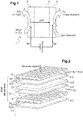
- the figure 2 shows an exploded view of elementary modules constituting the electrochemical stages of a high temperature water vapor electrolyser according to the state of the art.
- This EHT electrolyser comprises a plurality of electrolysis cells elementary Cl, C2 ... of solid oxide type (SOEC) stacked alternately with interconnectors 5.
- Each cell C1, C2 ... consists of a cathode 2.1, 2.2, ... and an anode 4.1, 4.2, between which is disposed an electrolyte 3.1, 3.2 .... All of the electrolysis cells are supplied in series by the electric current and in parallel by the gases.
- the interconnector 5 is a metal alloy component which ensures the separation between the cathode 50 and anode 51 compartments, defined by the volumes between the interconnector 5 and the adjacent cathode 2.1 and between the interconnector 5 and the adjacent anode 4.2 respectively. It also ensures the distribution of gases to the cells.
- the injection of water vapor into each elementary unit is carried out in the cathode compartment 50.
- the collection of the hydrogen produced and of the residual water vapor at the cathode 2.1, 2.2 ... is carried out in the cathode compartment 50 downstream of cell C1, C2 ... after dissociation of the water vapor by the latter.
- the collection of the oxygen produced at the anode 4.2 is carried out in the anode compartment 51 downstream of the cell C1, C2 ... after dissociation of the water vapor.
- the interconnector 5 ensures the passage of current between the cells C1 and C2 by direct contact with the adjacent electrodes, that is to say between the anode 4.2 and the cathode 2.1.
- the figure 3 shows an exploded view of elementary modules constituting the electrochemical stages of an SOFC fuel cell according to the state of the art: the same elementary patterns as those of the figure 2 are used for an SOFC fuel cell with cells of elementary cells C1, C2 and the interconnectors 5.
- the cathodes 2.1, 2.2 ... of the EHT electrolyzer are then used as anodes in the SOFC cell and the anodes 4.1, 4.2 ... of the EHT electrolyser are used as cathodes in SOFC cells.
- the injection of the air containing oxygen in each elementary unit is carried out in the cathode compartment SOFC 51.
- the water produced at the SOFC anode is collected in the anode compartment.
- the cells C1, C2 ... and interconnectors 5 used are the same components, but the operation is inverse of that of an EHT electrolyser as just explained with a reverse direction of the current, with air which supplies the SOFC cathode compartments and hydrogen as fuel which supplies the SOFC anode compartments .
- the operating point selected for the electrolysis reactor or the SOFC cell also fixes the thermal conditions in the stack.
- the energy ⁇ H necessary for the dissociation of the input molecule H2O or CO2
- electrochemical reactions necessary for the operation of this type of stack in an electrolyzer or SOFC fuel cell can be carried out under various electrical and thermal conditions, each having its own advantages and disadvantages.
- the exothermic mode for electrolysis as for the cell leads to a significant production either of hydrogen or of electricity, but the stack must be cooled, which can be difficult to achieve. Only a suitable interconnector design can provide cooling. The value of this exothermic mode then depends a lot on the cost of electricity and the use of excess heat.
- the elements internal to the SOFC cell or to the electrolyser, in particular the elementary cells, are made at least partly of ceramic, these are therefore very sensitive to temperature gradients and are not able to withstand a shock. thermal, nor too great a thermal gradient (a few tens of degrees between the inlet and the outlet of the gases).
- Some stack designs provide for adding tubes between the interconnection plates so as to circulate a gas in order to evacuate the calories: here we can cite the patent application WO2005 / 122302 .
- a stack of elementary patterns in an EHT electrolyser or in an SOFC stack also presents different boundary conditions from one adjacent pattern to another.
- the elementary patterns close to the ends of the stack can properly exchange heat with the external environment, which makes it possible to be able to manage their temperature to a certain extent.
- the elementary patterns at the center of the stack have no possible heat exchange with the external environment. For these reasons at the center of the stack, only the gases supplied to these zones can therefore make it possible to manage the thermal.
- Requirement WO2011 / 083691 concerns a SOEC electrolyser with the geometry of rectangular parallelepipedal blocks joined by heating elements, each block housing an electrolysis cell also of homothetic rectangular parallelepipedal shape consisting of a cathode, surrounded by an electrolyte membrane, itself surrounded by an anode, these components being deposited by the ALD (Atomic Layer Deposition) technique, each block being electrically isolated from those adjacent by means of an insulating layer also deposited by ALD or by CVD.
- ALD Atomic Layer Deposition
- the patent US4336122 describes an electrolyzer with electrodes in the form of superimposed metal plates being separated by annular spacers thereby defining spaces, the electrodes being connected in series.
- the liquid electrolyte circulates in the spaces and passes through the stack, certain spaces being shaped as baffles to circulate the electrolyte over the entire surface of the electrodes delimiting these spaces in order to cool the stack.
- WO2014 / 097101 refers to the simultaneous but separate co-electrolysis of water vapor and CO2.
- the interconnectors described comprise three flat sheets laminated and assembled together, forming electrochemical stages.
- Requirement EP 2980904 proposes to introduce fuel and air in the center of a stack.
- the air and fuel are supplied at the level of a heat exchanger stage arranged in the center of the stack.
- the gas circulates in a first part of the electrochemical cells and then passes into a second part of the electrochemical cells.
- air is simultaneously supplied to the level of the cathodes of the electrochemical cells.
- An aim of the invention is to respond at least in part to this need.
- the invention relates, under a first alternative, to a high temperature electrolysis reactor according to claim 1.
- the invention also relates, in a second alternative, to a high temperature fuel cell (SOFC) according to claim 2.
- SOFC high temperature fuel cell
- the electrical contact element allowing the gases to pass is a metal grid.
- the element can also be a set of discrete metal wires or a porous electronically conductive substrate.
- At least one of the two interconnectors of the thermal regulation stages consists of the same device as the interconnectors of the electrochemical stages, but do not include the seventh and eighth lights of the second end plate.
- the two interconnectors of the same electrochemical stage are each formed from three identical flat sheets but with the central sheet of one of the interconnectors turned over / below with respect to the central sheet of the other of the interconnectors.
- the invention essentially consists in creating a circuit of a heat transfer gas dedicated to the thermal regulation / management of the stack of an EHT reactor or of an SOFC fuel cell by eliminating certain cells in certain zones of stacking to replace them with electrical contact elements which can let the coolant gas through.
- a new type of stack is created in an EHT reactor or a SOFC fuel cell in which most of the usual electrochemical stages dedicated either to the (co-) electrolysis of water vapor are kept. or to the production of electricity by the battery, and stages with thermal regulation function are added to them instead of electrochemical stages in order to regulate the thermal reaction in these zones.
- the invention makes it possible not to have to make specific interconnectors with additions of tubes or with increased plate thicknesses or even with cooling fins in contact with outside.
- the thermal regulation stages according to the invention are produced with the same manufacturing, assembly and assembly tool as in a stack that does not integrate these stages.
- the coolant gas can be either the fuel, such as water vapor in (co-) electrolysis operating mode, or the draining gas or the oxidizer in SOFC cell operating mode.
- the fuel such as water vapor in (co-) electrolysis operating mode
- the draining gas or the oxidizer in SOFC cell operating mode For the two operating modes, SOFC or SOEC, provision is made to choose a porous material for the electrical contact which takes into account the oxidizing or reducing nature of the atmosphere of the heat transfer gas.
- the invention does not modify the reversibility of a stacked reactor which can be used both as an electrolysis or co-electrolysis reactor and as an SOFC cell with hydrogen or methane as fuel.
- the heat transfer gas (EH 2 (2)) is the fuel (water vapor H 2 O, or mixture of water vapor H 2 O and hydrogen H 2 , or mixture of water vapor H 2 O water H 2 O and carbon dioxide CO 2 ) or the draining gas, such as air, (E (02)).
- the fuel is preferably hydrogen or methane (CH 4 ).
- the fuel gas supply is connected in series to that of the coolant gas.
- the fuel gas supply can be in parallel (“coflow” in English) with that of the coolant gas.
- the fuel gas supply is counter-current to that of the coolant gas.
- an exothermic or endothermic chemical reaction can be carried out between the heat transfer gas and the electrical contact elements.
- support cathode cell is meant here and in the context of the invention the definition already given in the field of the electrolysis of water at high temperature EHT and designated by the English acronym CSC for “ Cathode- Supported Cell ”, that is to say a cell in which the electrolyte and the oxygen electrode (anode) are placed on the thicker hydrogen or carbon monoxide (cathode) electrode which therefore serves as a support .
- electrolysers described are of the solid oxide type (SOEC, acronym for “ Solid Oxide Electrosis Cell ”) operating at high temperature.
- SOEC Solid Oxide Electrosis Cell
- all the constituents (anode / electrolyte / cathode) of an electrolysis cell are ceramics.
- the high operating temperature of an electrolyser (electrolysis reactor) is typically between 600 ° C and 950 ° C.
- an SOEC elementary electrolysis cell suitable for the invention can be those indicated as follows in the table below.
- ⁇ b> ⁇ u>TABLE ⁇ /u> ⁇ /b> Electrolysis cell Unit Value Cathode 2 Constituent material Ni-YSZ Thickness ⁇ m 315 Thermal conductivity W m -1 K -1 13.1 Electrical conductivity ⁇ -1 m -1 10 5 Porosity 0.37 Permeability m 2 10 -13 Tortuousness 4 Current density Am -2 5300 Anode 4 Constituent material LSM Thickness ⁇ m 20 Thermal conductivity W m -1 K -1 9.6 Electrical conductivity ⁇ -1 m -1 1 10 4 Porosity 0.37 Permeability m 2 10 -13 Tortuousness 4 Current density Am -2 2000 Electrolyte 3 Constituent material YSZ Thickness ⁇ m 90 ⁇ m in support electrolyte and 5 ⁇ m in support electrode Resistivity ⁇ m 0.42
- the inventors have thought judiciously to integrate stages of thermal regulation within the stack by implementing flat sheet interconnectors very little modified in their structure compared to those dedicated to the electrochemical stages and by arranging electrical contact elements allowing the gases to pass instead of the cells of 'electrolysis.
- the coolant can advantageously be a mixture of water vapor and water. 'hydrogen.
- the hydrogen is present at at least 10% in order to avoid the oxidation of the contact elements 14, in particular in the form of a nickel grid.
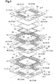
- This electrolysis reactor electrolyser comprises an alternating stack of an elementary electrolysis cell of SOEC type (C1) formed of a cathode 2.1, 2.2, an anode 4.1, 4.2 and an electrolyte 3.1, 3.2, intercalated between the cathode and the anode, and a metal grid 14.
- C1 elementary electrolysis cell of SOEC type
- This metal grid ensures electrical continuity in series through the thermal regulation stage.
- the electrochemical stage comprises two electrical and fluidic interconnectors 5.1, 5.2 arranged on either side of the elementary cell C1 with the cathode in electrical contact with the underside of the top interconnector 5.1 and the anode in electrical contact with the upper face of the interconnector from below 5.2.
- the thermal regulation stage also comprises two electrical and fluidic interconnectors 5.2, 5.3, of which the top one 5.2 is common with the electrochemical stage.
- the two interconnectors 5.2, 5.3 are arranged on either side of the metal grid 14.
- insulation and sealing frames 9 are also provided making it possible to ensure electrical insulation between interconnectors 5.1 and 5.2 on the one hand and between interconnectors 5.2, 5.3 on the other hand. It should be noted that between the two interconnectors 5.2 and 5.3, the frame 9 serves above all to achieve the seal, the electrical insulation not being required on the stage dedicated to thermal management.
- Each frame 9 is pierced with slots 99 adapted to accommodate tie rods for fixing the stack, as well as joints 10 provided for sealing around. lights for supplying H 2 O and Air gases and for recovering the gases produced H 2 , O 2 with Air, as well as around the clarinets dedicated to the heat transfer gas
- a contact layer 11, such as a nickel metal grid, makes it possible to ensure contact between the cathode of cell C1 and the interconnector 5.1 above.
- Another seal 12 is also provided at the periphery of the anode of the cell to seal the oxygen produced.
- the entire stack comprising the electrolysis cell C1 and the metal grid 11 for passing the heat transfer gas is traversed by the same electric current.
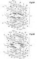
- an interconnector 5.3 dedicated to a thermal regulation stage is different from an interconnector 5.1 dedicated to an electrochemical stage in order to be able to provide only a supply of coolant gas, without the introduction of oxidizer, at a metal grid. 14.
- Each interconnector 5.1, 5.2 dedicated to an electrochemical stage makes it possible to ensure a circulation of the gas (H 2 O / H 2 ) at the cathodes of the cells with crossed current at 90 ° with the circulation of the recovered gas (02) and the draining gas at 90 °. the anode of the cells.
- the interconnector 5.1 or 5.2 consists of three flat sheets 6, 7, 8 elongated along two axes of symmetry (X, Y) orthogonal to each other, the flat sheets being laminated and assembled together by welding.
- a central sheet 7 is interposed between a first 6 and a second 8 end sheets.
- the first end plate 6 is intended to come into mechanical contact with the plane of a cathode 2.1 of the elementary electrolysis cell C1 and the central plate 7 is intended to come into mechanical contact with the plane of an anode 4.1.
- an adjacent elementary electrolysis cell each of the two adjacent elementary electrolysis cells (C1, C2) of SOEC type being formed of a cathode 2.1, 2.2, an anode 4.1, 4.2 and an electrolyte 3.1 , 3.2 interposed between the cathode and the anode.
- Each of the three flat sheets 6, 7, 8 has a central part 60, 70, 80.
- the central parts 60, 70 of the central sheet 7 and of the first end sheet 6 are not drilled while that 80 of the second end sheet 80 is pierced.
- Each sheet 6, 7, 8 is pierced, at the periphery of its central part, with six slots 61, 62, 63, 64, 65, 66; 71, 72, 73, 74, 75, 66; 81, 82, 83, 84, 85, 86.
- the first 61, 71, 81 to fourth 64, 74, 84 slots of each sheet are elongated over a length corresponding to part of the length of the central part 60, 70, 80 along one of the X axes of the sheets and are distributed in pairs on either side of said X axis.
- the fifth lumen 65, 75, 85 is elongated over a length corresponding substantially to the length of the central part 60, 70, 80 along the other of the Y axes.
- the sixth lumen 66, 76, 86 is elongated over a length corresponding substantially to the length of the central part 60, 70, 80 along the other of the Y axes.
- the first end plate 6 further comprises a seventh 67 and eighth 68 slots arranged symmetrically on either side of the X axis, inside its first to fourth slots 61 to 64, and are lying on a length corresponding substantially to the length of the central part along the X axis.
- the second 8 end plate further comprises a seventh light 87 and eighth 88 light arranged symmetrically on either side of the Y axis, inside respectively its fifth light 85 and its sixth light 86, and elongated. over a length substantially corresponding to the length of the central part along said Y axis.
- the first 71, third 73, fifth 75 and sixth 76 lights of the central sheet 7 are enlarged relative respectively to the first 61, 81, third 63, 83, fifth 65, 85 and sixth 66, 86 lights of each sheet of end 6, 8.
- the second 62, 72, 82 and fourth 64, 74, 84 lights of the three sheets are of substantially identical dimensions to each other.
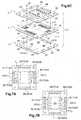
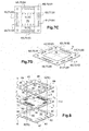
- the figures 9A and 9B show in detail the embodiment of the comb formed by the sheet metal tongues 710 at the level of the widened slot 71 of the central sheet and its arrangement between the two end sheets 6, 8 in order to allow the supply of a cell of electrolysis, here in water vapor H 2 O or of a metal grid 14 at a thermal regulation stage as detailed below.
- the formed comb 710, 711 allows the water vapor to pass from the supply clarinet 61, 71, 81 to the distribution slot 67 by passing through the space between the two end plates 6, 8
- the thickness of the central sheet 7 at the level of this comb 710, 711 gives it a spacer function and thus guarantees the height of the passage for the water vapor in the inter-end sheet space 6, 8
- Such a passage of the gases according to the invention through the interior of the interconnector 5.1 has the advantage of freeing a flat surface for producing the seals.
- interconnector 5.2 shown in figure 6B which makes it possible both to bring the draining gas to the level of the cell C1 and the heat transfer gas to the level of the metal grid 14, the same three flat sheets 6, 7, 8 are used as those used for the realization of the interconnector 5.1 but by only turning the central sheet 7 up and down before it is laminated and assembled with the two end sheets 6, 8.
- interconnector 5.3 shown in figure 8 which makes it possible not to bring draining gas or oxygen nor to recover oxidizing gas at the level of the metal grid 14, the same three flat sheets 6, 7, 8 as those used for the production of the interconnectors 5.1 and 5.2 are used, while retaining the 'set of lights dedicated to gas supply / recovery with the exception of lights 87, 88 which are deleted.
- interconnector 5.3 dedicated to a thermal regulation stage starting from exactly the same flat sheets 6, 7, 8 constituting the interconnectors 5.1, 5.2 dedicated to an electrochemical stage and removing them only the slots 87, 88 or slots usually dedicated to the function of supplying draining gas and recovering the oxygen O 2 produced.
- an alternating stack of thermal regulation stages and electrochemical stages is thus obtained, the thermal regulation of which, in particular at the center of the stack, is very effective and the production cost of which is lower compared to the solutions.
- all the interconnectors 5.1, 5.2, 5.3 are made with the same flat sheets 6, 7, 8 and therefore according to the same production ranges and certain electrolysis cells are replaced by metal grids which ensure electrical continuity through the stack.
- the first 61, 71, 81 lights are supplied with water vapor EH2 (1) from the interconnectors 5.1 to 5.3 and simultaneously the second 62, 72, 82 lights from the interconnector 5.1 to 5.3 with heat transfer gas EH2 (2).
- the heat transfer gas EH2 (2) passes through the interconnector 5.1 without being distributed to the cathode 2.1 of cell C1. It supplies the lights 62, 73, and 82 of interconnector 5.2.
- the water vapor EH2 (1) passes through the interconnector 5.2 without being distributed over the metal grid 14.
- the fifth light 65, 75, 85 of the three sheets 8 of each interconnector 5.1, 5.2, 5.3 is supplied with a draining gas E (O 2 ), such as air.
- the hydrogen produced SH2 (1) is thus recovered by the electrolysis of the water vapor at the level of the cell C1, in the third 63, 73, 83 ports of the interconnector 5.1.
- the heat transfer gas SH2 (2) having circulated for thermal management purposes at the level of the metal grid 14, in the fourth 64, 84 openings of the end plates and the first opening 71 of the interconnector 5.2 is separately recovered. .
- the oxygen O 2 produced S (O 2 ) is recovered in the sixth 66, 76, 86 ports of the three sheets 8 of each interconnector 5.1, 5.2.
- the supply of water vapor and recovery of produced hydrogen as well as the supply of draining gas and recovery of produced oxygen shown at figures 6A to 6C constitutes a circulation in co-current of fuel / heat transfer gas of a cell C1 with respect to the adjacent metal grid 14, and in cross-current with the circulation of draining gas / common product oxygen.
- interconnectors 5.1, 5.2 it is also possible, as a variant, to carry out countercurrent circulation of fuel / heat transfer gas from a cell C1 with respect to the adjacent metal grid 14, and at cross-current with the circulation of draining gas / oxygen produced.
- the three flat sheets 6, 7, 8 constituting each interconnector 5.1, 5.2, 5.3 according to the invention are thin flat metal sheets, drilled and assembled together by welding.
- the thin sheets are sheets of thickness less than 3 mm, typically of the order of 0.2 mm. All the welds between sheets made during manufacture, outside of any operation of the electrolyser can be advantageously carried out using a transparency laser technique, which is possible due to the low thickness of the thin sheets, typically of the order 0.2 mm.
- All the sheets are advantageously made of ferritic steel with around 20% chromium, preferably of CROFER® 22APU or FT18TNb, based on Nickel of the Inconel® 600 or Haynes® type in thicknesses typically between 0.1 and 1 mm.
- the three sheets 6, 7, 8 are pierced at their periphery with additional slots 69, 79, 89 adapted to accommodate tie rods.
- These fixing rods make it possible to apply a holding force to the stack of the various components of both the electrochemical stages and the thermal regulation stages of the electrolysis reactor.
- the heat transfer gas is of the water vapor type with hydrogen
- the draining gas is also the heat transfer gas.
- the heat transfer gas can be any gas, provided that it is suited to the material (s) of the contact elements 14, that is to say that it does not oxidize. these latter.
- the thermal regulation would be carried out by the draining gas (or oxidizing gas in an SOFC cell).
- the metal grid 14 is either a grid resistant to oxidation, or an electrical contact provided directly by welding to each other two successive interconnectors 5.2, 5.3. The welds between these two interconnectors 5.2, 5.3 must then ensure the seals and the passage of current.
- the electrochemical stages and the thermal regulation stages can be in parallel if the gas supply / recovery clarinets remain independent or in series if they are connected together outside the stack.
Landscapes
- Chemical & Material Sciences (AREA)
- Engineering & Computer Science (AREA)
- Chemical Kinetics & Catalysis (AREA)
- Electrochemistry (AREA)
- Organic Chemistry (AREA)
- Materials Engineering (AREA)
- Metallurgy (AREA)
- Sustainable Energy (AREA)
- Life Sciences & Earth Sciences (AREA)
- Manufacturing & Machinery (AREA)
- Sustainable Development (AREA)
- General Chemical & Material Sciences (AREA)
- Inorganic Chemistry (AREA)
- Automation & Control Theory (AREA)
- Combustion & Propulsion (AREA)
- Electrolytic Production Of Non-Metals, Compounds, Apparatuses Therefor (AREA)
- Fuel Cell (AREA)
Claims (15)
- Reaktor zur Hochtemperaturelektrolyse (HTE), der einen alternierenden Stapel aus zwei verschiedenen Gruppen von Stufen umfasst, darunter:- eine Gruppe aus einer Mehrzahl von Stufen, elektrochemische Stufen genannt, die jeweils aus einer elementaren Elektrolysezelle (C1, C2, C3) vom Festoxidtyp SOEC, die aus einer Kathode (2.1, 2.2, ...), einer Anode (4.1, 4.2, ...) und einem zwischen der Kathode und der Anode angeordneten Elektrolyten (3.1, 3.2 ...) gebildet ist, und aus zwei Interkonnektoren (5.1, 5.2), die jeweils zum elektrischen und fluidischen Verbinden geeignet sind und die beidseits der elementaren Zelle (C1, C2) angeordnet sind, bestehen,- eine Gruppe aus mindestens einer Stufe, Wärmeregulierungsstufe(n) genannt, die aus mindestens einem elektrischen Kontaktelement (14), das die Gase durchlässt, und aus zwei Interkonnektoren (5.2, 5.3), die jeweils zum elektrischen und fluidischen Verbinden geeignet sind und die beidseits des Kontaktelements angeordnet sind, besteht(bestehen), wobei das Kontaktelement ein Metallgitter, eine Anordnung aus diskreten Metalldrähten oder ein elektronisches leitfähiges poröses Substrat ist,wobei die Interkonnektoren der elektrochemischen Stufen und der thermischen Stufe(n) dazu geeignet sind, gleichzeitig:• durch den Stapel hindurch Wasserdampf (EH2(1)) oder ein Gemisch aus Wasserdampf H2O und Kohlendioxid CO2, ein Trocknungsgas wie Luft (E(O2)) und ein Wärmeträgergas (EH2(2)) strömen zu lassen,• den erzeugten Wasserstoff H2 (SH2(1)) oder das Synthesegas (Gemisch aus Kohlenmonoxid CO und Wasserstoff H2), das an den Kathoden der Zellen erzeugt wird, den an den Anoden der Zellen erzeugten Sauerstoff O2 (S(O2)) und das Trocknungsgas und das Wärmeträgergas (SH2(2)) am Auslass der Elemente (14) zurückzugewinnen, wobei der für die elektrochemischen Stufen dedizierte Teil der Interkonnektoren ferner dazu geeignet ist, gleichzeitig Wasserdampf (EH2(1)) oder das Gemisch aus Wasserdampf H2O und Kohlendioxid CO2 zu den Kathoden der Zellen und das Trocknungsgas (E(O2)) zu den Anoden der Zellen zu verteilen,während der für die Wärmeregulierungsstufe(n) dedizierte Teil der Interkonnektoren dazu geeignet ist, nur das Wärmeträgergas zu dem(den) elektrischen Kontaktelement(en) (14), das(die) die Gase durchlässt(durchlassen), zu verteilen.
- Hochtemperatur-Brennstoffzelle (SOFC), die einen alternierenden Stapel aus zwei verschiedenen Gruppen von Stufen umfasst, darunter:- eine Gruppe aus einer Mehrzahl von Stufen, elektrochemische Stufen genannt, die jeweils aus einer elementaren elektrochemischen Zelle (C1, C2, C3) vom Festoxidtyp SOFC, die aus einer Kathode (2.1, 2.2, ...), einer Anode (4.1, 4.2, ...) und einem zwischen der Kathode und der Anode angeordneten Elektrolyten (3.1, 3.2 ...) gebildet ist, und aus zwei Interkonnektoren (5.1, 5.2), die jeweils zum elektrischen und fluidischen Verbinden geeignet sind und die beidseits der elementaren Zelle (C1, C2) angeordnet sind, bestehen,- eine Gruppe aus mindestens einer Stufe, Wärmeregulierungsstufe(n) genannt, die aus mindestens einem elektrischen Kontaktelement (14), das die Gase durchlässt, und aus zwei Interkonnektoren (5.2, 5.3), die jeweils zum elektrischen und fluidischen Verbinden geeignet sind und die beidseits des Kontaktelements angeordnet sind, besteht(bestehen), wobei das Kontaktelement ein Metallgitter, eine Anordnung aus diskreten Metalldrähten oder ein elektronisches leitfähiges poröses Substrat ist,wobei die Interkonnektoren der elektrochemischen Stufen und der thermischen Stufe(n) dazu geeignet sind, gleichzeitig:• durch den Stapel hindurch einen Brennstoff (EH2(1)), ein Oxidationsmittel wie Luft (E(O2)) und ein Wärmeträgergas (EH2(2)) strömen zu lassen,• den Brennstoffüberschuss und das erzeugte Wasser (SH2(1)) an den Anoden der Zellen, den Oxidationsmittelüberschuss (S(O2)) an den Kathoden der Zellen und das Wärmeträgergas (SH2(2)) am Auslass der Elemente (14) zurückzugewinnen,wobei der für die elektrochemischen Stufen dedizierte Teil der Interkonnektoren ferner dazu geeignet ist, gleichzeitig den Brennstoff (EH2(1)) zu den Anoden der Zellen und das Oxidationsmittel (E(O2)) zu den Anoden der Zellen zu verteilen,
während der für die Wärmeregulierungsstufe(n) dedizierte Teil der Interkonnektoren dazu geeignet ist, nur das Wärmeträgergas zu dem (den) elektrischen Kontaktelement(en) (14), das(die) die Gase durchlässt(durchlassen), zu verteilen. - Reaktor zur Hochtemperaturelektrolyse (HTE) oder Hochtemperatur-Brennstoffzelle (SOFC) nach Anspruch 1 oder 2, wobei das die Gase durchlassende elektrische Kontaktelement ein Metallgitter ist.
- Reaktor zur Hochtemperaturelektrolyse (HTE) oder Hochtemperatur-Brennstoffzelle (SOFC) nach einem der Ansprüche 1 bis 3, wobei die Interkonnektoren der elektrochemischen Stufen jeweils in einer Vorrichtung bestehen, die aus drei ebenen Blechen (6, 7, 8) besteht, die entlang von zwei zueinander rechtwinkligen Symmetrieachsen (X, Y) langgestreckt sind, wobei eines der endständigen Bleche dazu bestimmt ist, mit der Ebene einer Kathode (2) einer elementaren Zelle (C2) in mechanischen Kontakt zu gelangen, und das andere der endständigen Bleche dazu bestimmt ist, mit der Ebene einer Anode (4) einer benachbarten elementaren Zelle (C1) in mechanischen Kontakt zu gelangen, wobei in der Vorrichtung:- die zentralen Teile (60, 70) des zentralen Blechs (7) und eines der endständigen Bleche, erstes endständiges Blech (6) genannt, nicht durchbrochen sind, während der zentrale Teil (8) des anderen endständigen Blechs, zweites endständiges Blech (8) genannt, durchbrochen ist (80),- jedes der drei ebenen Bleche (6, 7, 8) am Umfang seines zentralen Teils mit mindestens sechs Schlitzen (61, 62, 63, 64, 65, 66; 71, 72, 73, 74, 75, 76; 81, 82, 83, 84, 85, 86) durchbrochen ist, wobei die ersten bis vierten Schlitze (61 bis 64; 71 bis 74; 81 bis 84) jedes Blechs über eine Länge, die einem Teil der Länge des zentralen Teils entspricht, entlang einer der Achsen X der Bleche langgestreckt sind und paarweise beidseits der Achse X verteilt sind, während die fünften und sechsten Schlitze (65, 75, 85; 66, 76, 86) über eine Länge, die im Wesentlichen der Länge des zentralen Teils entspricht, entlang der anderen der Achsen Y langgestreckt sind,- das erste endständige Blech (6) ferner einen siebten (67) und einen achten (68) Schlitz umfasst, die symmetrisch beidseits der Achse X innerhalb seiner ersten bis vierten Schlitze (61, 62, 63, 64) angeordnet sind und über eine Länge, die im Wesentlichen der Länge des zentralen Teils entspricht, entlang der Achse X langgestreckt sind,- das zweite (8) der endständigen Bleche ferner einen siebten (87) und einen achten (88) Schlitz umfasst, die symmetrisch beidseits der Achse Y innerhalb seines fünften (85) beziehungsweise seines sechsten (86) Schlitzes angeordnet sind und über eine Länge, die im Wesentlichen der Länge des zentralen Teils entspricht, entlang der Achse Y langgestreckt sind,- die ersten (71), dritten (73), fünften (75) und sechsten Schlitze des zentralen Blechs (7) in Bezug auf die ersten (61, 81), dritten (63, 83), fünften (65, 85) beziehungsweise sechsten (66, 86) Schlitze jedes endständigen Blechs verbreitert sind, während die zweiten (62, 72, 82) und vierten (64, 74, 84) Schlitze der drei Bleche im Wesentlichen die gleichen Abmessungen haben,- alle verbreiterten Schlitze (71, 73, 75, 76) des zentralen Blechs (7) in ihrem verbreiterten Teil Blechzungen umfassen, die voneinander beabstandet sind und dabei einen Kamm bilden, wobei jeder der Spalte, der zwischen dem Rand eines verbreiterten Spalts (71, 73, 75, 76) und einer Zunge oder zwischen zwei aufeinander folgenden Zungen definiert ist, an einem der inneren Schlitze des ersten (6) oder zweiten (8) endständigen Blechs mündet,- die drei Bleche (6, 7, 8) so geschichtet und zusammengefügt sind, dass:• die Blechzungen Abstandsstege zwischen ersten (6) und zweiten (8) endständigen Blechen jeweils zwischen den ersten (61) und siebten (67) Schlitzen des ersten endständigen Blechs (6), zwischen den dritten (63) und achten (68) Schlitzen des ersten endständigen Blechs (6), zwischen den fünften (85) und siebten (87) Schlitzen des zweiten endständigen Blechs (8) und zwischen den sechsten (86) und achten (88) Schlitzen des zweiten endständigen Blechs (8) bilden,• jeder der ersten bis sechsten Schlitze (61 bis 66) des einen der drei Bleche einzeln in Fluidverbindung mit jeweils einem der entsprechenden ersten bis sechsten Schlitze (71 bis 76; 81 bis 86) der beiden anderen Bleche steht,• der erste (61) oder alternativ der zweite (62) Schlitz des ersten (6) endständigen Blechs in Fluidverbindung mit dem siebten (66) Schlitz des ersten (6) endständigen Blechs über Spalte des ersten (71) verbreiterten Schlitzes des zentralen Blechs (7) steht,• der dritte (63) oder alternativ der vierte (64) Schlitz des ersten (6) endständigen Blechs in Fluidverbindung mit dem achten (68) Schlitz des ersten (6) endständigen Blechs über Spalte des dritten (73) verbreiterten Schlitzes des zentralen Blechs (7) steht,• der fünfte (85) und der siebte (87) Schlitz des zweiten (8) endständigen Blechs in Fluidverbindung über Spalte des fünften (75) verbreiterten Schlitzes des zentralen Blechs (7) stehen,• der sechste (86) und der achte (88) Schlitz des zweiten (8) endständigen Blechs in Fluidverbindung über Spalte des sechsten (76) verbreiterten Schlitzes des zentralen Blechs (7) stehen.
- Reaktor zur Hochtemperaturelektrolyse (HTE) oder Hochtemperatur-Brennstoffzelle (SOFC) nach Anspruch 4, wobei mindestens einer der beiden Interkonnektoren der Wärmeregulierungsstufen aus den drei Blechen besteht, welche die Interkonnektoren der elektrochemischen Stufen, aber nicht die siebten (87) und achten (88) Schlitze des zweiten endständigen Blechs (8) umfassen.
- Reaktor zur Hochtemperaturelektrolyse (HTE) oder Hochtemperatur-Brennstoffzelle (SOFC) nach Anspruch 4 oder 5, wobei die beiden Interkonnektoren derselben elektrochemischen Stufe (5.1, 5.2) jeweils aus drei identischen ebenen Blechen (6, 7, 8) bestehen, wobei jedoch das zentrale Blech des einen der Interkonnektoren in Bezug auf das zentrale Blech des anderen der Interkonnektoren von oben nach unten gewendet ist.
- Reaktor zur Hochtemperaturelektrolyse (HTE) oder Hochtemperatur-Brennstoffzelle (SOFC) nach einem der vorhergehenden Ansprüche, umfassend eine Anzahl von Wärmeregulierungsstufen, die verschieden von der Anzahl der elektrochemischen Stufen ist.
- Reaktor zur Hochtemperaturelektrolyse (HTE) oder Hochtemperatur-Brennstoffzelle (SOFC) nach einem der vorhergehenden Ansprüche, umfassend eine Anzahl von Wärmeregulierungsstufen, die im Zentrum des Stapels größer als an den Enden des Stapels ist.
- Reaktor zur Hochtemperaturelektrolyse (HTE) oder Hochtemperatur-Brennstoffzelle (SOFC) nach einem der vorhergehenden Ansprüche, bei dem(der) keine Wärmeregulierungsstufe von außerhalb des Stapels sichtbar ist.
- Verfahren zur Hochtemperaturelektrolyse von Wasserdampf H2O oder zur Co-Elektrolyse von Wasserdampf H2O und Kohlendioxid CO2, das in einem Reaktor nach einem der Anspruche 1 oder 3 bis 9 durchgeführt wird, bei dem:- von den Interkonnektoren (5.1, 5.2) der elektrochemischen Stufen aus Wasserdampf (EH2(1)) oder ein Gemisch aus Wasserdampf H2O und Kohlendioxid CO2 als Brennstoff zugeführt wird und zu den Kathoden der Zellen verteilt wird, dann der erzeugte Wasserstoff H2 (SH2(1)) oder das Synthesegas (Gemisch aus Kohlenmonoxid CO und Wasserstoff H2) am Auslass der Kathoden zurückgewonnen werden,- von den Interkonnektoren (5.1, 5.2) der elektrochemischen Stufen aus ein Trocknungsgas wie Luft (E(O2)) zugeführt wird und zu den Anoden der Zellen verteilt wird, dann der erzeugte Sauerstoff O2 und das Trocknungsgas (S(O2)) am Auslass der Anoden zurückgewonnen werden,- von den Interkonnektoren (5.2, 5.3) der Wärmeregulierungsstufen aus ein Wärmeträgergas (EH2(2)) zugeführt wird und zu den elektrischen Kontaktelementen (14) verteilt wird, es dann am Auslass der Elemente (14) zurückgewonnen wird,wobei das Wärmeträgergas (EH2(2)) bevorzugt der Brennstoff (Wasserdampf H2O oder Gemisch aus Wasserdampf H2O und Wasserstoff H2 oder Gemisch aus Wasserdampf H2O und Kohlendioxid CO2) oder das Trocknungsgas wie Luft (E(O2)) ist.
- Verfahren zur Stromerzeugung bei hoher Temperatur, das in einer Festoxid-Brennstoffzelle (SOFC) nach einem der Ansprüche 2 bis 9 durchgeführt wird, bei dem:- von den Interkonnektoren (5.1, 5.2) der elektrochemischen Stufen aus der Brennstoff (EH2(1)) zugeführt wird und zu den Anoden der Zellen verteilt wird, dann der Brennstoffüberschuss und das erzeugte Wasser (SH2(1)) am Auslass der Anoden zurückgewonnen werden,- von den Interkonnektoren (5.1, 5.2) der elektrochemischen Stufen aus das Oxidationsmittel wie Luft (E(O2)) zugeführt wird und zu den Kathoden der Zellen verteilt wird, dann der Oxidationsmittelüberschuss (S(O2)) am Auslass der Kathoden zurückgewonnen wird,- von den Interkonnektoren (5.2, 5.3) der Wärmeregulierungsstufen aus ein Wärmeträgergas (EH2(2)) zugeführt und zu den elektrischen Kontaktelementen (14) verteilt wird, es dann am Auslass der Elemente (14) zurückgewonnen wird.wobei der Brennstoff bevorzugt Wasserstoff oder Methan (CH4) ist.
- Verfahren zur Hochtemperaturelektrolyse von Wasserdampf H2O oder zur Co-Elektrolyse von Wasserdampf H2O und Kohlendioxid CO2 nach Anspruch 10 und Verfahren zur Stromerzeugung bei hoher Temperatur nach Anspruch 12, bei dem die Zufuhr des Brennstoffgases in Reihe mit der des Wärmeträgergases angeschlossen ist.
- Verfahren zur Hochtemperaturelektrolyse von Wasserdampf H2O oder zur Co-Elektrolyse von Wasserdampf H2O und Kohlendioxid CO2 nach einem der Ansprüche 10 oder 12 und Verfahren zur Stromerzeugung bei hoher Temperatur nach einem der Ansprüche 11 oder 12, bei dem die Zufuhr des Brenngases parallel zu der des Wärmeträgergases ist.
- Verfahren zur Hochtemperaturelektrolyse von Wasserdampf H2O oder zur Co-Elektrolyse von Wasserdampf H2O und Kohlendioxid CO2 nach einem der Ansprüche 10 oder 12 und Verfahren zur Stromerzeugung bei hoher Temperatur nach einem der Ansprüche 11 oder 12, bei dem die Zufuhr des Brenngases im Gegenstrom zu der des Wärmeträgergases erfolgt.
- Verfahren zur Hochtemperaturelektrolyse von Wasserdampf H2O oder zur Co-Elektrolyse von Wasserdampf H2O und Kohlendioxid CO2 nach einem der Ansprüche 10 oder 12 bis 14 und Verfahren zur Stromerzeugung bei hoher Temperatur nach einem der Ansprüche 11 oder 12 bis 14, bei dem eine exotherme oder endotherme chemische Reaktion zwischen dem Wärmeträgergas und den elektrischen Kontaktelementen (14) durchgeführt wird.
Applications Claiming Priority (2)
| Application Number | Priority Date | Filing Date | Title |
|---|---|---|---|
| FR1556727A FR3038916B1 (fr) | 2015-07-16 | 2015-07-16 | Procedes d' (de co) electrolyse de l'eau (soec) ou de production d'electricite a haute temperature a echangeurs integres en tant qu'etages d'un empilement de reacteur (eht) ou d'une pile a combustible (sofc) |
| PCT/EP2016/066304 WO2017009238A1 (fr) | 2015-07-16 | 2016-07-08 | Procedes d' (de co) electrolyse de l'eau (soec) ou de production d'electricite a haute temperature a echangeurs integres en tant qu'etages d'un empilement de reacteur (eht) ou d'une pile a combustible (sofc) |
Publications (2)
| Publication Number | Publication Date |
|---|---|
| EP3322839A1 EP3322839A1 (de) | 2018-05-23 |
| EP3322839B1 true EP3322839B1 (de) | 2021-04-28 |
Family
ID=54608682
Family Applications (1)
| Application Number | Title | Priority Date | Filing Date |
|---|---|---|---|
| EP16736471.0A Active EP3322839B1 (de) | 2015-07-16 | 2016-07-08 | Verfahren zur (co)elektrolyse von wasser oder zur stromerzeugung bei hoher temperatur mit austauschern als stufen eines reaktorstapels oder einer brennstoffzelle |
Country Status (7)
| Country | Link |
|---|---|
| US (1) | US10597788B2 (de) |
| EP (1) | EP3322839B1 (de) |
| JP (1) | JP6620236B2 (de) |
| CA (1) | CA2992130C (de) |
| DK (1) | DK3322839T3 (de) |
| FR (1) | FR3038916B1 (de) |
| WO (1) | WO2017009238A1 (de) |
Families Citing this family (9)
| Publication number | Priority date | Publication date | Assignee | Title |
|---|---|---|---|---|
| FR3040061B1 (fr) * | 2015-08-12 | 2017-09-08 | Commissariat Energie Atomique | Procedes d' (de co-) electrolyse de l'eau (soec) ou de production d'electricite a haute temperature a faibles gradients thermiques au sein respectivement d'un reacteur ou d'une pile a combustible (sofc) |
| US11767600B2 (en) | 2018-11-06 | 2023-09-26 | Utility Global, Inc. | Hydrogen production system |
| US11761096B2 (en) | 2018-11-06 | 2023-09-19 | Utility Global, Inc. | Method of producing hydrogen |
| WO2020123389A1 (en) * | 2018-12-10 | 2020-06-18 | Utility Global, Inc. | Balance of plant for electrochemical reactors |
| CN109830732A (zh) * | 2019-01-25 | 2019-05-31 | 哈尔滨工业大学(深圳) | 一种不对称平板型结构高温固态燃料电池的电堆结构 |
| JP2022553873A (ja) * | 2019-11-12 | 2022-12-26 | レドックス パワー システムズ, エルエルシー | 固体酸化物電気化学セルのスタック構造体 |
| US11777126B2 (en) | 2019-12-05 | 2023-10-03 | Utility Global, Inc. | Methods of making and using an oxide ion conducting membrane |
| WO2023139504A1 (en) * | 2022-01-18 | 2023-07-27 | Bloom Energy Corporation | Compressor integration and safe operation start up for atmospheric operation of soec systems |
| AT525448B1 (de) * | 2022-06-27 | 2023-04-15 | H2i GreenHydrogen GmbH | Anschlusseinheit für Zellstapel |
Citations (1)
| Publication number | Priority date | Publication date | Assignee | Title |
|---|---|---|---|---|
| WO2014156314A1 (ja) * | 2013-03-29 | 2014-10-02 | 日本特殊陶業株式会社 | 燃料電池 |
Family Cites Families (13)
| Publication number | Priority date | Publication date | Assignee | Title |
|---|---|---|---|---|
| US4336122A (en) * | 1980-09-08 | 1982-06-22 | Ernst Spirig | Electrolysis apparatus |
| US4574112A (en) | 1983-12-23 | 1986-03-04 | United Technologies Corporation | Cooling system for electrochemical fuel cell |
| US7718293B2 (en) * | 2002-10-14 | 2010-05-18 | Reinz-Dichtungs-Gmbh | Electrochemical system with fluid passage integrated within a sealing bead |
| US20060105213A1 (en) | 2003-03-05 | 2006-05-18 | Kazuhiko Otsuka | Separator, fuel cell device, and temperature control method for fuel cell device |
| US20050064270A1 (en) * | 2003-09-24 | 2005-03-24 | Marianowski Leonard G. | Fuel cell bipolar separator plate |
| FR2870388B1 (fr) | 2004-05-12 | 2006-08-25 | Peugeot Citroen Automobiles Sa | Cellule de pile a combustible a electrolyte solide |
| IL173539A0 (en) * | 2006-02-05 | 2006-07-05 | Rami Noach | Flow distributor plate |
| FR2921390B1 (fr) * | 2007-09-25 | 2010-12-03 | Commissariat Energie Atomique | Electrolyseur haute temperature a dispositif d'homogeneisation de la temperature. |
| US9614232B2 (en) * | 2007-12-28 | 2017-04-04 | Altergy Systems | Modular unit fuel cell assembly |
| WO2011083691A1 (ja) * | 2010-01-07 | 2011-07-14 | コニカミノルタホールディングス株式会社 | 燃料電池 |
| FR2982085B1 (fr) | 2011-10-28 | 2014-05-16 | Commissariat Energie Atomique | Systeme electrochimique type electrolyseur ou pile a combustible haute temperature a gestion thermique amelioree |
| FR2999612B1 (fr) * | 2012-12-17 | 2015-02-20 | Commissariat Energie Atomique | Procede d'electrolyse a haute temperature de la vapeur d'eau et d'un autre gaz, interconnecteur, reacteur et procedes de fonctionnement associes |
| JP6110488B2 (ja) * | 2013-06-28 | 2017-04-05 | 京セラ株式会社 | セルユニット、セルスタック装置、セルユニット装置およびモジュール |
-
2015
- 2015-07-16 FR FR1556727A patent/FR3038916B1/fr not_active Expired - Fee Related
-
2016
- 2016-07-08 US US15/744,144 patent/US10597788B2/en active Active
- 2016-07-08 JP JP2018521695A patent/JP6620236B2/ja active Active
- 2016-07-08 EP EP16736471.0A patent/EP3322839B1/de active Active
- 2016-07-08 WO PCT/EP2016/066304 patent/WO2017009238A1/fr active Application Filing
- 2016-07-08 DK DK16736471.0T patent/DK3322839T3/da active
- 2016-07-08 CA CA2992130A patent/CA2992130C/fr active Active
Patent Citations (2)
| Publication number | Priority date | Publication date | Assignee | Title |
|---|---|---|---|---|
| WO2014156314A1 (ja) * | 2013-03-29 | 2014-10-02 | 日本特殊陶業株式会社 | 燃料電池 |
| EP2980904A1 (de) * | 2013-03-29 | 2016-02-03 | NGK Sparkplug Co., Ltd. | Brennstoffbatterie |
Also Published As
| Publication number | Publication date |
|---|---|
| US20180202055A1 (en) | 2018-07-19 |
| FR3038916B1 (fr) | 2017-07-28 |
| WO2017009238A1 (fr) | 2017-01-19 |
| JP6620236B2 (ja) | 2019-12-11 |
| CA2992130C (fr) | 2020-11-24 |
| CA2992130A1 (fr) | 2017-01-19 |
| DK3322839T3 (da) | 2021-07-26 |
| FR3038916A1 (fr) | 2017-01-20 |
| EP3322839A1 (de) | 2018-05-23 |
| JP2018528329A (ja) | 2018-09-27 |
| US10597788B2 (en) | 2020-03-24 |
Similar Documents
| Publication | Publication Date | Title |
|---|---|---|
| EP3322839B1 (de) | Verfahren zur (co)elektrolyse von wasser oder zur stromerzeugung bei hoher temperatur mit austauschern als stufen eines reaktorstapels oder einer brennstoffzelle | |
| EP3183379B1 (de) | Verfahren für hochtemperaturelektrolyse oder co-elektrolyse, verfahren zur erzeugung von strom mittels einer sofc-brennstoffzelle und zugehörige verbinder, reaktoren und betriebsverfahren | |
| EP2931943B1 (de) | Verfahren zur hochtemperaturelektrolyse von dampf und anderen gasen, zugehöriger interkonnektor, elektrolysereaktor und betriebsverfahren | |
| EP3516718B1 (de) | Verfahren zur co-elektrolyse von wasser und co2 (soec) oder zur hochtemperaturelektrizitätserzeugung (sofc) mit optionaler förderung von katalytischen reaktionen innerhalb der h2-elektrode | |
| CA3063286C (fr) | Reacteur d'electrolyse ou de co-electrolyse de l'eau (soec) ou pile a combustible (sofc) a fonctionnement sous pression et a systeme de serrage adapte a un tel fonctionnement | |
| WO2014097191A1 (fr) | Cadre d'isolation électrique et d'étanchéité pour réacteur d'électrolyse de l'eau (soec) ou pile à combustible (sofc) | |
| EP3516721B1 (de) | Wasserelektrolysereaktor (soec) oder brennstoffzelle (sofc) mit erhöhter wasserdampf- oder brennstoffeinsatzrate | |
| EP3955353A1 (de) | Elektrolyse- oder co-elektrolyse-reaktor (soec) oder brennstoffzelle (sofc) mit einem stapel elektrochemischer zellen in vormontierten modulen und entsprechendes herstellungsverfahren | |
| WO2015101924A1 (fr) | Interconnecteur electrique et fluidique pour electrolyseur eht ou pile a combustible sofc. | |
| EP3335264B1 (de) | Verfahren zur wasser (ko-)elektrolyse bzw. stromerzeugung bei hohen temperaturen, mit niedrigen thermischen gradienten, innerhalb eines elektrochemischen reaktors (soec) bzw. einer brennstoffzelle (sofc) | |
| EP3233270B1 (de) | Elementares modul für einen reaktor zur ausführung von wasserelektrolyse (hte) oder h2o/co2-co-elektrolyse oder eine sofc-brennstoffzelle und für einen reaktor zur katalytischen methanisierung oder reformierung | |
| EP3888168A1 (de) | Interkonnektor für reaktor zur elektrolyse oder co-elektrolyse von wasser (soec) oder brennstoffzelle (soefc), zugehöriges herstellungsverfahren | |
| WO2023052721A1 (fr) | Interconnecteur pour empilement de cellules à oxydes solides de type soec/sofc comportant des éléments en relief différents | |
| EP4315462A1 (de) | Verfahren zur herstellung eines soec/sofc-festoxidstapels und zugehöriger stapel | |
| CA3233399A1 (fr) | Interconnecteur pour empilement de cellules a oxydes solides de type soec/sofc comportant des languettes de geometrie optimisee |
Legal Events
| Date | Code | Title | Description |
|---|---|---|---|
| STAA | Information on the status of an ep patent application or granted ep patent |
Free format text: STATUS: THE INTERNATIONAL PUBLICATION HAS BEEN MADE |
|
| PUAI | Public reference made under article 153(3) epc to a published international application that has entered the european phase |
Free format text: ORIGINAL CODE: 0009012 |
|
| STAA | Information on the status of an ep patent application or granted ep patent |
Free format text: STATUS: REQUEST FOR EXAMINATION WAS MADE |
|
| 17P | Request for examination filed |
Effective date: 20180216 |
|
| AK | Designated contracting states |
Kind code of ref document: A1 Designated state(s): AL AT BE BG CH CY CZ DE DK EE ES FI FR GB GR HR HU IE IS IT LI LT LU LV MC MK MT NL NO PL PT RO RS SE SI SK SM TR |
|
| AX | Request for extension of the european patent |
Extension state: BA ME |
|
| DAV | Request for validation of the european patent (deleted) | ||
| DAX | Request for extension of the european patent (deleted) | ||
| STAA | Information on the status of an ep patent application or granted ep patent |
Free format text: STATUS: EXAMINATION IS IN PROGRESS |
|
| 17Q | First examination report despatched |
Effective date: 20181212 |
|
| GRAP | Despatch of communication of intention to grant a patent |
Free format text: ORIGINAL CODE: EPIDOSNIGR1 |
|
| STAA | Information on the status of an ep patent application or granted ep patent |
Free format text: STATUS: GRANT OF PATENT IS INTENDED |
|
| INTG | Intention to grant announced |
Effective date: 20201119 |
|
| GRAS | Grant fee paid |
Free format text: ORIGINAL CODE: EPIDOSNIGR3 |
|
| GRAA | (expected) grant |
Free format text: ORIGINAL CODE: 0009210 |
|
| STAA | Information on the status of an ep patent application or granted ep patent |
Free format text: STATUS: THE PATENT HAS BEEN GRANTED |
|
| AK | Designated contracting states |
Kind code of ref document: B1 Designated state(s): AL AT BE BG CH CY CZ DE DK EE ES FI FR GB GR HR HU IE IS IT LI LT LU LV MC MK MT NL NO PL PT RO RS SE SI SK SM TR |
|
| REG | Reference to a national code |
Ref country code: GB Ref legal event code: FG4D Free format text: NOT ENGLISH |
|
| REG | Reference to a national code |
Ref country code: CH Ref legal event code: EP |
|
| REG | Reference to a national code |
Ref country code: AT Ref legal event code: REF Ref document number: 1387129 Country of ref document: AT Kind code of ref document: T Effective date: 20210515 |
|
| REG | Reference to a national code |
Ref country code: DE Ref legal event code: R096 Ref document number: 602016056885 Country of ref document: DE |
|
| REG | Reference to a national code |
Ref country code: IE Ref legal event code: FG4D Free format text: LANGUAGE OF EP DOCUMENT: FRENCH |
|
| REG | Reference to a national code |
Ref country code: DK Ref legal event code: T3 Effective date: 20210720 |
|
| REG | Reference to a national code |
Ref country code: LT Ref legal event code: MG9D |
|
| REG | Reference to a national code |
Ref country code: AT Ref legal event code: MK05 Ref document number: 1387129 Country of ref document: AT Kind code of ref document: T Effective date: 20210428 |
|
| PG25 | Lapsed in a contracting state [announced via postgrant information from national office to epo] |
Ref country code: FI Free format text: LAPSE BECAUSE OF FAILURE TO SUBMIT A TRANSLATION OF THE DESCRIPTION OR TO PAY THE FEE WITHIN THE PRESCRIBED TIME-LIMIT Effective date: 20210428 Ref country code: LT Free format text: LAPSE BECAUSE OF FAILURE TO SUBMIT A TRANSLATION OF THE DESCRIPTION OR TO PAY THE FEE WITHIN THE PRESCRIBED TIME-LIMIT Effective date: 20210428 Ref country code: NL Free format text: LAPSE BECAUSE OF FAILURE TO SUBMIT A TRANSLATION OF THE DESCRIPTION OR TO PAY THE FEE WITHIN THE PRESCRIBED TIME-LIMIT Effective date: 20210428 Ref country code: HR Free format text: LAPSE BECAUSE OF FAILURE TO SUBMIT A TRANSLATION OF THE DESCRIPTION OR TO PAY THE FEE WITHIN THE PRESCRIBED TIME-LIMIT Effective date: 20210428 Ref country code: BG Free format text: LAPSE BECAUSE OF FAILURE TO SUBMIT A TRANSLATION OF THE DESCRIPTION OR TO PAY THE FEE WITHIN THE PRESCRIBED TIME-LIMIT Effective date: 20210728 Ref country code: AT Free format text: LAPSE BECAUSE OF FAILURE TO SUBMIT A TRANSLATION OF THE DESCRIPTION OR TO PAY THE FEE WITHIN THE PRESCRIBED TIME-LIMIT Effective date: 20210428 |
|
| PG25 | Lapsed in a contracting state [announced via postgrant information from national office to epo] |
Ref country code: NO Free format text: LAPSE BECAUSE OF FAILURE TO SUBMIT A TRANSLATION OF THE DESCRIPTION OR TO PAY THE FEE WITHIN THE PRESCRIBED TIME-LIMIT Effective date: 20210728 Ref country code: PT Free format text: LAPSE BECAUSE OF FAILURE TO SUBMIT A TRANSLATION OF THE DESCRIPTION OR TO PAY THE FEE WITHIN THE PRESCRIBED TIME-LIMIT Effective date: 20210830 Ref country code: PL Free format text: LAPSE BECAUSE OF FAILURE TO SUBMIT A TRANSLATION OF THE DESCRIPTION OR TO PAY THE FEE WITHIN THE PRESCRIBED TIME-LIMIT Effective date: 20210428 Ref country code: RS Free format text: LAPSE BECAUSE OF FAILURE TO SUBMIT A TRANSLATION OF THE DESCRIPTION OR TO PAY THE FEE WITHIN THE PRESCRIBED TIME-LIMIT Effective date: 20210428 Ref country code: SE Free format text: LAPSE BECAUSE OF FAILURE TO SUBMIT A TRANSLATION OF THE DESCRIPTION OR TO PAY THE FEE WITHIN THE PRESCRIBED TIME-LIMIT Effective date: 20210428 Ref country code: LV Free format text: LAPSE BECAUSE OF FAILURE TO SUBMIT A TRANSLATION OF THE DESCRIPTION OR TO PAY THE FEE WITHIN THE PRESCRIBED TIME-LIMIT Effective date: 20210428 Ref country code: GR Free format text: LAPSE BECAUSE OF FAILURE TO SUBMIT A TRANSLATION OF THE DESCRIPTION OR TO PAY THE FEE WITHIN THE PRESCRIBED TIME-LIMIT Effective date: 20210729 Ref country code: IS Free format text: LAPSE BECAUSE OF FAILURE TO SUBMIT A TRANSLATION OF THE DESCRIPTION OR TO PAY THE FEE WITHIN THE PRESCRIBED TIME-LIMIT Effective date: 20210828 |
|
| REG | Reference to a national code |
Ref country code: NL Ref legal event code: MP Effective date: 20210428 |
|
| PG25 | Lapsed in a contracting state [announced via postgrant information from national office to epo] |
Ref country code: RO Free format text: LAPSE BECAUSE OF FAILURE TO SUBMIT A TRANSLATION OF THE DESCRIPTION OR TO PAY THE FEE WITHIN THE PRESCRIBED TIME-LIMIT Effective date: 20210428 Ref country code: ES Free format text: LAPSE BECAUSE OF FAILURE TO SUBMIT A TRANSLATION OF THE DESCRIPTION OR TO PAY THE FEE WITHIN THE PRESCRIBED TIME-LIMIT Effective date: 20210428 Ref country code: CZ Free format text: LAPSE BECAUSE OF FAILURE TO SUBMIT A TRANSLATION OF THE DESCRIPTION OR TO PAY THE FEE WITHIN THE PRESCRIBED TIME-LIMIT Effective date: 20210428 Ref country code: EE Free format text: LAPSE BECAUSE OF FAILURE TO SUBMIT A TRANSLATION OF THE DESCRIPTION OR TO PAY THE FEE WITHIN THE PRESCRIBED TIME-LIMIT Effective date: 20210428 Ref country code: SM Free format text: LAPSE BECAUSE OF FAILURE TO SUBMIT A TRANSLATION OF THE DESCRIPTION OR TO PAY THE FEE WITHIN THE PRESCRIBED TIME-LIMIT Effective date: 20210428 Ref country code: SK Free format text: LAPSE BECAUSE OF FAILURE TO SUBMIT A TRANSLATION OF THE DESCRIPTION OR TO PAY THE FEE WITHIN THE PRESCRIBED TIME-LIMIT Effective date: 20210428 |
|
| REG | Reference to a national code |
Ref country code: DE Ref legal event code: R097 Ref document number: 602016056885 Country of ref document: DE |
|
| PLBE | No opposition filed within time limit |
Free format text: ORIGINAL CODE: 0009261 |
|
| STAA | Information on the status of an ep patent application or granted ep patent |
Free format text: STATUS: NO OPPOSITION FILED WITHIN TIME LIMIT |
|
| PG25 | Lapsed in a contracting state [announced via postgrant information from national office to epo] |
Ref country code: MC Free format text: LAPSE BECAUSE OF FAILURE TO SUBMIT A TRANSLATION OF THE DESCRIPTION OR TO PAY THE FEE WITHIN THE PRESCRIBED TIME-LIMIT Effective date: 20210428 |
|
| REG | Reference to a national code |
Ref country code: BE Ref legal event code: MM Effective date: 20210731 |
|
| 26N | No opposition filed |
Effective date: 20220131 |
|
| PG25 | Lapsed in a contracting state [announced via postgrant information from national office to epo] |
Ref country code: IS Free format text: LAPSE BECAUSE OF FAILURE TO SUBMIT A TRANSLATION OF THE DESCRIPTION OR TO PAY THE FEE WITHIN THE PRESCRIBED TIME-LIMIT Effective date: 20210828 Ref country code: LU Free format text: LAPSE BECAUSE OF NON-PAYMENT OF DUE FEES Effective date: 20210708 Ref country code: AL Free format text: LAPSE BECAUSE OF FAILURE TO SUBMIT A TRANSLATION OF THE DESCRIPTION OR TO PAY THE FEE WITHIN THE PRESCRIBED TIME-LIMIT Effective date: 20210428 |
|
| PG25 | Lapsed in a contracting state [announced via postgrant information from national office to epo] |
Ref country code: IE Free format text: LAPSE BECAUSE OF NON-PAYMENT OF DUE FEES Effective date: 20210708 Ref country code: BE Free format text: LAPSE BECAUSE OF NON-PAYMENT OF DUE FEES Effective date: 20210731 |
|
| PG25 | Lapsed in a contracting state [announced via postgrant information from national office to epo] |
Ref country code: HU Free format text: LAPSE BECAUSE OF FAILURE TO SUBMIT A TRANSLATION OF THE DESCRIPTION OR TO PAY THE FEE WITHIN THE PRESCRIBED TIME-LIMIT; INVALID AB INITIO Effective date: 20160708 |
|
| P01 | Opt-out of the competence of the unified patent court (upc) registered |
Effective date: 20230517 |
|
| PG25 | Lapsed in a contracting state [announced via postgrant information from national office to epo] |
Ref country code: CY Free format text: LAPSE BECAUSE OF FAILURE TO SUBMIT A TRANSLATION OF THE DESCRIPTION OR TO PAY THE FEE WITHIN THE PRESCRIBED TIME-LIMIT Effective date: 20210428 |
|
| PGFP | Annual fee paid to national office [announced via postgrant information from national office to epo] |
Ref country code: IT Payment date: 20230731 Year of fee payment: 8 Ref country code: GB Payment date: 20230724 Year of fee payment: 8 Ref country code: CH Payment date: 20230801 Year of fee payment: 8 |
|
| PGFP | Annual fee paid to national office [announced via postgrant information from national office to epo] |
Ref country code: FR Payment date: 20230724 Year of fee payment: 8 Ref country code: DK Payment date: 20230724 Year of fee payment: 8 Ref country code: DE Payment date: 20230720 Year of fee payment: 8 |
|
| REG | Reference to a national code |
Ref country code: GB Ref legal event code: 732E Free format text: REGISTERED BETWEEN 20240111 AND 20240117 |
|
| PG25 | Lapsed in a contracting state [announced via postgrant information from national office to epo] |
Ref country code: MK Free format text: LAPSE BECAUSE OF FAILURE TO SUBMIT A TRANSLATION OF THE DESCRIPTION OR TO PAY THE FEE WITHIN THE PRESCRIBED TIME-LIMIT Effective date: 20210428 |