EP3322579B1 - 3-d printing device - Google Patents
3-d printing device Download PDFInfo
- Publication number
- EP3322579B1 EP3322579B1 EP16757142.1A EP16757142A EP3322579B1 EP 3322579 B1 EP3322579 B1 EP 3322579B1 EP 16757142 A EP16757142 A EP 16757142A EP 3322579 B1 EP3322579 B1 EP 3322579B1
- Authority
- EP
- European Patent Office
- Prior art keywords
- printing
- unit
- head unit
- nozzle
- base plate
- Prior art date
- Legal status (The legal status is an assumption and is not a legal conclusion. Google has not performed a legal analysis and makes no representation as to the accuracy of the status listed.)
- Active
Links
- 238000007639 printing Methods 0.000 title claims description 441
- 239000000463 material Substances 0.000 claims description 206
- 238000010438 heat treatment Methods 0.000 claims description 192
- 238000010146 3D printing Methods 0.000 claims description 129
- 238000000034 method Methods 0.000 claims description 122
- 230000008569 process Effects 0.000 claims description 103
- 238000001816 cooling Methods 0.000 claims description 93
- 230000001105 regulatory effect Effects 0.000 claims description 56
- 238000001035 drying Methods 0.000 claims description 21
- 239000004033 plastic Substances 0.000 claims description 20
- 229920003023 plastic Polymers 0.000 claims description 20
- 238000005259 measurement Methods 0.000 claims description 19
- 230000001276 controlling effect Effects 0.000 claims description 9
- 230000008859 change Effects 0.000 claims description 7
- 229920006258 high performance thermoplastic Polymers 0.000 claims description 6
- 230000000087 stabilizing effect Effects 0.000 claims description 2
- 230000033228 biological regulation Effects 0.000 description 20
- 230000006870 function Effects 0.000 description 20
- 230000006641 stabilisation Effects 0.000 description 15
- 238000011105 stabilization Methods 0.000 description 15
- 239000000835 fiber Substances 0.000 description 14
- 239000004696 Poly ether ether ketone Substances 0.000 description 11
- JUPQTSLXMOCDHR-UHFFFAOYSA-N benzene-1,4-diol;bis(4-fluorophenyl)methanone Chemical compound OC1=CC=C(O)C=C1.C1=CC(F)=CC=C1C(=O)C1=CC=C(F)C=C1 JUPQTSLXMOCDHR-UHFFFAOYSA-N 0.000 description 11
- 229920002530 polyetherether ketone Polymers 0.000 description 11
- XLYOFNOQVPJJNP-UHFFFAOYSA-N water Substances O XLYOFNOQVPJJNP-UHFFFAOYSA-N 0.000 description 11
- 238000004519 manufacturing process Methods 0.000 description 9
- 229920001652 poly(etherketoneketone) Polymers 0.000 description 9
- 229920006260 polyaryletherketone Polymers 0.000 description 9
- 238000002844 melting Methods 0.000 description 7
- 230000008018 melting Effects 0.000 description 7
- 238000000576 coating method Methods 0.000 description 6
- 230000007423 decrease Effects 0.000 description 6
- XAGFODPZIPBFFR-UHFFFAOYSA-N aluminium Chemical compound [Al] XAGFODPZIPBFFR-UHFFFAOYSA-N 0.000 description 5
- 229910052782 aluminium Inorganic materials 0.000 description 5
- 230000006399 behavior Effects 0.000 description 5
- 239000011248 coating agent Substances 0.000 description 5
- 230000005855 radiation Effects 0.000 description 5
- 238000010586 diagram Methods 0.000 description 4
- 239000011521 glass Substances 0.000 description 3
- 238000009434 installation Methods 0.000 description 3
- 239000010445 mica Substances 0.000 description 3
- 229910052618 mica group Inorganic materials 0.000 description 3
- 239000000758 substrate Substances 0.000 description 3
- OKTJSMMVPCPJKN-UHFFFAOYSA-N Carbon Chemical compound [C] OKTJSMMVPCPJKN-UHFFFAOYSA-N 0.000 description 2
- 229920000049 Carbon (fiber) Polymers 0.000 description 2
- 239000000654 additive Substances 0.000 description 2
- 230000004888 barrier function Effects 0.000 description 2
- 229910052799 carbon Inorganic materials 0.000 description 2
- 239000004917 carbon fiber Substances 0.000 description 2
- 239000000919 ceramic Substances 0.000 description 2
- 239000004053 dental implant Substances 0.000 description 2
- 230000008021 deposition Effects 0.000 description 2
- 238000013461 design Methods 0.000 description 2
- 238000009826 distribution Methods 0.000 description 2
- 239000007788 liquid Substances 0.000 description 2
- 238000004886 process control Methods 0.000 description 2
- 239000007787 solid Substances 0.000 description 2
- 238000012360 testing method Methods 0.000 description 2
- UONOETXJSWQNOL-UHFFFAOYSA-N tungsten carbide Chemical compound [W+]#[C-] UONOETXJSWQNOL-UHFFFAOYSA-N 0.000 description 2
- 229910001369 Brass Inorganic materials 0.000 description 1
- 229920000106 Liquid crystal polymer Polymers 0.000 description 1
- 239000004977 Liquid-crystal polymers (LCPs) Substances 0.000 description 1
- 238000007545 Vickers hardness test Methods 0.000 description 1
- 230000004913 activation Effects 0.000 description 1
- 238000013459 approach Methods 0.000 description 1
- 229920003235 aromatic polyamide Polymers 0.000 description 1
- 239000010951 brass Substances 0.000 description 1
- 239000004566 building material Substances 0.000 description 1
- 239000007795 chemical reaction product Substances 0.000 description 1
- 210000000078 claw Anatomy 0.000 description 1
- 239000003086 colorant Substances 0.000 description 1
- 238000011109 contamination Methods 0.000 description 1
- 230000009849 deactivation Effects 0.000 description 1
- 210000004513 dentition Anatomy 0.000 description 1
- 238000001514 detection method Methods 0.000 description 1
- 238000011161 development Methods 0.000 description 1
- 230000018109 developmental process Effects 0.000 description 1
- 239000012153 distilled water Substances 0.000 description 1
- 230000000694 effects Effects 0.000 description 1
- 229920006351 engineering plastic Polymers 0.000 description 1
- 230000004927 fusion Effects 0.000 description 1
- 230000012447 hatching Effects 0.000 description 1
- 125000000623 heterocyclic group Chemical group 0.000 description 1
- 230000001771 impaired effect Effects 0.000 description 1
- 238000009413 insulation Methods 0.000 description 1
- 239000013067 intermediate product Substances 0.000 description 1
- 238000012423 maintenance Methods 0.000 description 1
- 230000007246 mechanism Effects 0.000 description 1
- 239000000155 melt Substances 0.000 description 1
- 230000000704 physical effect Effects 0.000 description 1
- 229920001643 poly(ether ketone) Polymers 0.000 description 1
- 229920001660 poly(etherketone-etherketoneketone) Polymers 0.000 description 1
- 229920001230 polyarylate Polymers 0.000 description 1
- 229920000642 polymer Polymers 0.000 description 1
- 229920001296 polysiloxane Polymers 0.000 description 1
- 238000003825 pressing Methods 0.000 description 1
- 238000012545 processing Methods 0.000 description 1
- 238000000275 quality assurance Methods 0.000 description 1
- 239000005336 safety glass Substances 0.000 description 1
- 239000011265 semifinished product Substances 0.000 description 1
- 238000007711 solidification Methods 0.000 description 1
- 230000008023 solidification Effects 0.000 description 1
- 238000003860 storage Methods 0.000 description 1
- 239000000126 substance Substances 0.000 description 1
- 238000001931 thermography Methods 0.000 description 1
- 229920001169 thermoplastic Polymers 0.000 description 1
- 239000004416 thermosoftening plastic Substances 0.000 description 1
- 230000036346 tooth eruption Effects 0.000 description 1
Images


Classifications
-
- B—PERFORMING OPERATIONS; TRANSPORTING
- B29—WORKING OF PLASTICS; WORKING OF SUBSTANCES IN A PLASTIC STATE IN GENERAL
- B29C—SHAPING OR JOINING OF PLASTICS; SHAPING OF MATERIAL IN A PLASTIC STATE, NOT OTHERWISE PROVIDED FOR; AFTER-TREATMENT OF THE SHAPED PRODUCTS, e.g. REPAIRING
- B29C64/00—Additive manufacturing, i.e. manufacturing of three-dimensional [3D] objects by additive deposition, additive agglomeration or additive layering, e.g. by 3D printing, stereolithography or selective laser sintering
- B29C64/10—Processes of additive manufacturing
- B29C64/106—Processes of additive manufacturing using only liquids or viscous materials, e.g. depositing a continuous bead of viscous material
- B29C64/118—Processes of additive manufacturing using only liquids or viscous materials, e.g. depositing a continuous bead of viscous material using filamentary material being melted, e.g. fused deposition modelling [FDM]
-
- B—PERFORMING OPERATIONS; TRANSPORTING
- B29—WORKING OF PLASTICS; WORKING OF SUBSTANCES IN A PLASTIC STATE IN GENERAL
- B29C—SHAPING OR JOINING OF PLASTICS; SHAPING OF MATERIAL IN A PLASTIC STATE, NOT OTHERWISE PROVIDED FOR; AFTER-TREATMENT OF THE SHAPED PRODUCTS, e.g. REPAIRING
- B29C64/00—Additive manufacturing, i.e. manufacturing of three-dimensional [3D] objects by additive deposition, additive agglomeration or additive layering, e.g. by 3D printing, stereolithography or selective laser sintering
- B29C64/10—Processes of additive manufacturing
- B29C64/106—Processes of additive manufacturing using only liquids or viscous materials, e.g. depositing a continuous bead of viscous material
-
- B—PERFORMING OPERATIONS; TRANSPORTING
- B29—WORKING OF PLASTICS; WORKING OF SUBSTANCES IN A PLASTIC STATE IN GENERAL
- B29C—SHAPING OR JOINING OF PLASTICS; SHAPING OF MATERIAL IN A PLASTIC STATE, NOT OTHERWISE PROVIDED FOR; AFTER-TREATMENT OF THE SHAPED PRODUCTS, e.g. REPAIRING
- B29C64/00—Additive manufacturing, i.e. manufacturing of three-dimensional [3D] objects by additive deposition, additive agglomeration or additive layering, e.g. by 3D printing, stereolithography or selective laser sintering
- B29C64/20—Apparatus for additive manufacturing; Details thereof or accessories therefor
- B29C64/205—Means for applying layers
- B29C64/209—Heads; Nozzles
-
- B—PERFORMING OPERATIONS; TRANSPORTING
- B29—WORKING OF PLASTICS; WORKING OF SUBSTANCES IN A PLASTIC STATE IN GENERAL
- B29C—SHAPING OR JOINING OF PLASTICS; SHAPING OF MATERIAL IN A PLASTIC STATE, NOT OTHERWISE PROVIDED FOR; AFTER-TREATMENT OF THE SHAPED PRODUCTS, e.g. REPAIRING
- B29C64/00—Additive manufacturing, i.e. manufacturing of three-dimensional [3D] objects by additive deposition, additive agglomeration or additive layering, e.g. by 3D printing, stereolithography or selective laser sintering
- B29C64/20—Apparatus for additive manufacturing; Details thereof or accessories therefor
- B29C64/245—Platforms or substrates
-
- B—PERFORMING OPERATIONS; TRANSPORTING
- B29—WORKING OF PLASTICS; WORKING OF SUBSTANCES IN A PLASTIC STATE IN GENERAL
- B29C—SHAPING OR JOINING OF PLASTICS; SHAPING OF MATERIAL IN A PLASTIC STATE, NOT OTHERWISE PROVIDED FOR; AFTER-TREATMENT OF THE SHAPED PRODUCTS, e.g. REPAIRING
- B29C64/00—Additive manufacturing, i.e. manufacturing of three-dimensional [3D] objects by additive deposition, additive agglomeration or additive layering, e.g. by 3D printing, stereolithography or selective laser sintering
- B29C64/20—Apparatus for additive manufacturing; Details thereof or accessories therefor
- B29C64/255—Enclosures for the building material, e.g. powder containers
- B29C64/259—Interchangeable
-
- B—PERFORMING OPERATIONS; TRANSPORTING
- B29—WORKING OF PLASTICS; WORKING OF SUBSTANCES IN A PLASTIC STATE IN GENERAL
- B29C—SHAPING OR JOINING OF PLASTICS; SHAPING OF MATERIAL IN A PLASTIC STATE, NOT OTHERWISE PROVIDED FOR; AFTER-TREATMENT OF THE SHAPED PRODUCTS, e.g. REPAIRING
- B29C64/00—Additive manufacturing, i.e. manufacturing of three-dimensional [3D] objects by additive deposition, additive agglomeration or additive layering, e.g. by 3D printing, stereolithography or selective laser sintering
- B29C64/20—Apparatus for additive manufacturing; Details thereof or accessories therefor
- B29C64/295—Heating elements
-
- B—PERFORMING OPERATIONS; TRANSPORTING
- B29—WORKING OF PLASTICS; WORKING OF SUBSTANCES IN A PLASTIC STATE IN GENERAL
- B29C—SHAPING OR JOINING OF PLASTICS; SHAPING OF MATERIAL IN A PLASTIC STATE, NOT OTHERWISE PROVIDED FOR; AFTER-TREATMENT OF THE SHAPED PRODUCTS, e.g. REPAIRING
- B29C64/00—Additive manufacturing, i.e. manufacturing of three-dimensional [3D] objects by additive deposition, additive agglomeration or additive layering, e.g. by 3D printing, stereolithography or selective laser sintering
- B29C64/30—Auxiliary operations or equipment
- B29C64/307—Handling of material to be used in additive manufacturing
- B29C64/321—Feeding
- B29C64/336—Feeding of two or more materials
-
- B—PERFORMING OPERATIONS; TRANSPORTING
- B29—WORKING OF PLASTICS; WORKING OF SUBSTANCES IN A PLASTIC STATE IN GENERAL
- B29C—SHAPING OR JOINING OF PLASTICS; SHAPING OF MATERIAL IN A PLASTIC STATE, NOT OTHERWISE PROVIDED FOR; AFTER-TREATMENT OF THE SHAPED PRODUCTS, e.g. REPAIRING
- B29C64/00—Additive manufacturing, i.e. manufacturing of three-dimensional [3D] objects by additive deposition, additive agglomeration or additive layering, e.g. by 3D printing, stereolithography or selective laser sintering
- B29C64/30—Auxiliary operations or equipment
- B29C64/386—Data acquisition or data processing for additive manufacturing
- B29C64/393—Data acquisition or data processing for additive manufacturing for controlling or regulating additive manufacturing processes
-
- B—PERFORMING OPERATIONS; TRANSPORTING
- B33—ADDITIVE MANUFACTURING TECHNOLOGY
- B33Y—ADDITIVE MANUFACTURING, i.e. MANUFACTURING OF THREE-DIMENSIONAL [3-D] OBJECTS BY ADDITIVE DEPOSITION, ADDITIVE AGGLOMERATION OR ADDITIVE LAYERING, e.g. BY 3-D PRINTING, STEREOLITHOGRAPHY OR SELECTIVE LASER SINTERING
- B33Y10/00—Processes of additive manufacturing
-
- B—PERFORMING OPERATIONS; TRANSPORTING
- B33—ADDITIVE MANUFACTURING TECHNOLOGY
- B33Y—ADDITIVE MANUFACTURING, i.e. MANUFACTURING OF THREE-DIMENSIONAL [3-D] OBJECTS BY ADDITIVE DEPOSITION, ADDITIVE AGGLOMERATION OR ADDITIVE LAYERING, e.g. BY 3-D PRINTING, STEREOLITHOGRAPHY OR SELECTIVE LASER SINTERING
- B33Y30/00—Apparatus for additive manufacturing; Details thereof or accessories therefor
-
- B—PERFORMING OPERATIONS; TRANSPORTING
- B33—ADDITIVE MANUFACTURING TECHNOLOGY
- B33Y—ADDITIVE MANUFACTURING, i.e. MANUFACTURING OF THREE-DIMENSIONAL [3-D] OBJECTS BY ADDITIVE DEPOSITION, ADDITIVE AGGLOMERATION OR ADDITIVE LAYERING, e.g. BY 3-D PRINTING, STEREOLITHOGRAPHY OR SELECTIVE LASER SINTERING
- B33Y50/00—Data acquisition or data processing for additive manufacturing
- B33Y50/02—Data acquisition or data processing for additive manufacturing for controlling or regulating additive manufacturing processes
-
- B—PERFORMING OPERATIONS; TRANSPORTING
- B33—ADDITIVE MANUFACTURING TECHNOLOGY
- B33Y—ADDITIVE MANUFACTURING, i.e. MANUFACTURING OF THREE-DIMENSIONAL [3-D] OBJECTS BY ADDITIVE DEPOSITION, ADDITIVE AGGLOMERATION OR ADDITIVE LAYERING, e.g. BY 3-D PRINTING, STEREOLITHOGRAPHY OR SELECTIVE LASER SINTERING
- B33Y70/00—Materials specially adapted for additive manufacturing
-
- B—PERFORMING OPERATIONS; TRANSPORTING
- B29—WORKING OF PLASTICS; WORKING OF SUBSTANCES IN A PLASTIC STATE IN GENERAL
- B29K—INDEXING SCHEME ASSOCIATED WITH SUBCLASSES B29B, B29C OR B29D, RELATING TO MOULDING MATERIALS OR TO MATERIALS FOR MOULDS, REINFORCEMENTS, FILLERS OR PREFORMED PARTS, e.g. INSERTS
- B29K2061/00—Use of condensation polymers of aldehydes or ketones or derivatives thereof, as moulding material
-
- B—PERFORMING OPERATIONS; TRANSPORTING
- B29—WORKING OF PLASTICS; WORKING OF SUBSTANCES IN A PLASTIC STATE IN GENERAL
- B29K—INDEXING SCHEME ASSOCIATED WITH SUBCLASSES B29B, B29C OR B29D, RELATING TO MOULDING MATERIALS OR TO MATERIALS FOR MOULDS, REINFORCEMENTS, FILLERS OR PREFORMED PARTS, e.g. INSERTS
- B29K2071/00—Use of polyethers, e.g. PEEK, i.e. polyether-etherketone or PEK, i.e. polyetherketone or derivatives thereof, as moulding material
-
- B—PERFORMING OPERATIONS; TRANSPORTING
- B29—WORKING OF PLASTICS; WORKING OF SUBSTANCES IN A PLASTIC STATE IN GENERAL
- B29K—INDEXING SCHEME ASSOCIATED WITH SUBCLASSES B29B, B29C OR B29D, RELATING TO MOULDING MATERIALS OR TO MATERIALS FOR MOULDS, REINFORCEMENTS, FILLERS OR PREFORMED PARTS, e.g. INSERTS
- B29K2995/00—Properties of moulding materials, reinforcements, fillers, preformed parts or moulds
- B29K2995/0018—Properties of moulding materials, reinforcements, fillers, preformed parts or moulds having particular optical properties, e.g. fluorescent or phosphorescent
- B29K2995/002—Coloured
Definitions
- the invention relates to a 3D printing device.
- a 3-D printing device in particular an FFF printing device, at least one printhead unit and with at least one feeding device, which is provided in at least one operating state to feed a printing material to the at least one printhead unit, the printhead unit being provided for this in at least one operating state to melt a printing material formed at least partially from a high-performance plastic, in particular a high-performance thermoplastic.
- the previously known 3-D printing device is provided with a base unit which is provided with at least one heatable, in particular controllably heatable, printing base plate on which printing is carried out during a printing process.
- a printing material which is suitable for a 3-D printing device, wherein at least one component of the printing material consists of PAEK, while another component of this printing material consists of a material different from the above-mentioned PAEK material.
- a 3-D printing device in particular an FFF printing device, with at least one print head unit and with at least one feed device, which is provided in at least one operating state for the at least one print head unit a printing material is fed, previously known.
- This print head unit is provided in at least one operating state to melt a print material formed at least partially from a high-performance plastic, in particular a high-performance thermoplastic, the 3-D printing device having a base unit with at least one heatable, in particular controllably heatable, printing base plate on which during a printing process is printed.
- a surface heating unit is arranged opposite this printing base plate, which is provided to at least partially heat a printing object arranged on the printing base plate from a direction different from the printing base plate.
- the at least one pressure base plate and the mentioned at least one surface heating unit are here executed movable relative to each other.
- a local heating unit is provided which, in an operating state, is able to partially heat a print object before another layer is imprinted by the at least one print head unit
- a 3D printing device in particular an FFF printing device, with at least one print head unit and with at least one feed device which is provided in at least one operating state to feed a printing material to the at least one print head unit is already known.
- this 3D printing device has a feed device with which printing material in the form of a filament is fed to the print head unit.
- this feed device is provided with a transport element in order to move the printing material at a defined feed rate.
- this printing device is provided with a heatable printing base plate.
- a 3D printing device is also previously known in which a cooling device is assigned to the printing base plate.
- a 3D printing device which has a chamber for receiving a substrate carrier, as well as a conveyor module for the printing material and a dispensing nozzle for dispensing the modeling substance, so that this is a 3D printer in which the three-dimensional printing form is applied during the printing process the substrate carrier is applied.
- a radiant heater is assigned to the substrate carrier, which is equipped with several temperature sensors and includes several separately controllable radiant heaters.
- the object of the invention is in particular to provide a device of the generic type with improved properties with regard to the processability of engineering plastics.
- the object is achieved according to the invention by the features of claim 1, while advantageous configurations and developments of the invention can be found in the subclaims.
- the invention is based on a 3D printing device, in particular an FFF printing device, with at least one print head unit and with at least one feed device, which is provided in at least one operating state to supply a printing material to the at least one print head unit.
- the print head unit is provided in at least one operating state to melt a printing material formed at least partially from a high-performance plastic, in particular a high-performance thermoplastic.
- the print head unit is preferably provided to melt a printing material formed at least partially from a PAEK, particularly preferably from a PEEK and / or PEKK.
- a “3D printing device” is to be understood in particular as a device which is provided for a three-dimensional structure of a workpiece.
- an FFF printing device is to be understood in particular as a 3D printing device in which a workpiece is built up by means of “fused filament fabrication”, in particular by means of “fused deposition modeling”.
- Fused Filament Fabrication describes in particular a manufacturing method from the field of rapid prototyping, in which a workpiece is built up in layers from a material, in particular from a plastic, particularly preferably from a filament.
- a “print head unit”, in particular a preferably movable unit of the 3D printing device, is to be understood through which printing material is applied directly to a printing surface in an operation.
- the print head unit preferably has at least one nozzle via which a printing material is applied, in particular extruded.
- a “feed device” is to be understood in particular as a device which is provided to feed a printing material to the print head unit during operation.
- the feed device is preferably provided for providing a printing material on the print head unit.
- Preferred should this is understood to mean in particular a device which is provided to transport a printing material from a memory to the print head unit. A transport takes place in particular in a defined amount and / or at a defined feed rate.
- “Provided” is to be understood in particular as specifically programmed, designed and / or equipped. The fact that an object is provided for a specific function should be understood in particular to mean that the object fulfills and / or executes this specific function in at least one application and / or operating state.
- a "high-performance plastic” is to be understood in particular as a plastic, preferably a thermoplastic, which has a heat resistance of more than 150.degree.
- Various high-performance plastics that appear sensible to a person skilled in the art are conceivable, such as, for example, polyaryls, polyarylates, polyaramides, heterocyclic polymers, liquid crystal polymers and / or polyaryletherketones.
- PAEK is to be understood in particular as the group of polyaryl ether ketones, to which, for example, PEEK, PEK, PEKEKK and PEKK belong.
- the inventive design of the 3D printing device can in particular provide a printing device by means of which at least high-performance plastics, in particular high-performance thermoplastics, can be processed. In this way, it can be achieved in particular that technical components and components that are exposed to high thermal loads can also be produced by means of a 3D printing device.
- the 3D printing device be designed as a 3D dental printing device.
- the 3D printing device can preferably be used to produce dental objects, in particular for the production of dental implants, temporaries, inlays and / or dentures.
- a "3D dental printing device” is to be understood as meaning, in particular, a 3D printing device that is provided for the production of elements in the dental field, in particular of dental objects such as semi-finished products, intermediate products and / or end products.
- an advantageous embodiment of the 3D printing device can be provided. In principle, however, other applications of the 3D printing device that appear sensible to a person skilled in the art are also conceivable.
- dental objects in particular individual dental objects, can advantageously be produced quickly and easily.
- the 3D printing device for the production of dental objects in particular for the production of dental implants, temporaries, inlays and / or dentures, is provided to apply a printing material to an individually three-dimensional printing surface.
- the printing surface is preferably formed by a dental positive impression model.
- a dental object can in particular be printed directly on an image of the patient's dentition.
- the use of support material can in particular be avoided.
- printing can thereby be realized particularly advantageously quickly.
- a corresponding possible implementation can be found in the German Offenlegungsschrift DE 10 2013 111 387 A1 can be removed.
- the 3D printing device has a base unit with at least one heatable, in particular controllably heatable, printing base plate on which printing is carried out during a printing process.
- the pressure base plate can preferably be heated in a controllable manner in segments.
- the segments of the pressure base plate are preferably designed to be separately controllable.
- the segments of the pressure base plate can be controlled separately via a control and / or regulating unit.
- the pressure base plate can preferably be heated to different degrees in this way via the control and / or regulating unit. In this way, in particular, targeted heating can be achieved. Furthermore, an advantageously efficient printing base plate can thereby be achieved.
- a “printing base plate” is to be understood as meaning in particular an element or a unit which at least partially forms a background for a print. Preferably, this is to be understood in particular as an element or a unit on which an object to be printed is built.
- a first layer of a print object is preferably built up directly on the print base plate.
- the printing base plate is preferably formed by a rectangular, in particular flat, plate on which printing is carried out during printing. In principle, however, an uneven, such as a curved shape of the plate would also be conceivable.
- a temperature of the pressure base plate is preferably at least controllable, particularly preferably regulatable. This allows an object to be printed to be advantageous be heated from a base. This can prevent an object to be printed from cooling down too quickly.
- the 3D printing device has at least one surface heating unit arranged opposite the printing base plate, which is provided to at least partially heat a printing object arranged on the printing base plate from a direction different from the printing base plate.
- the surface heating unit is preferably provided to at least partially heat a print object from one side and / or particularly preferably from above.
- the fact that “the surface heating unit is arranged opposite the printing base plate” is to be understood in this context in particular as the printing area in which a print object is built up during operation of the 3D printing device is at least partially arranged between the printing base plate and the surface heating unit.
- the surface heating unit is arranged at least partially in an area which extends upwards perpendicular to a pressure surface of the pressure base plate.
- a “surface heating unit” is to be understood as meaning, in particular, a unit which is provided at least partially for the planar generation of heating power.
- a heating power is preferably generated over an area of at least 10 cm 2 , preferably of at least 50 cm 2 and particularly preferably of at least 100 cm 2 .
- this is to be understood as a unit which is provided for the generation of planar heating radiation.
- heating radiation is particularly preferably aligned at least substantially perpendicular to a surface of the surface heating unit.
- the surface heating unit in principle, however, other configurations of the surface heating unit that appear sensible to a person skilled in the art are also conceivable.
- the surface heating unit it would also be conceivable for the surface heating unit to be designed as a microwave heating unit, which is provided for targeted emission of microwaves for partial heating of the printed object.
- the fact that “the surface heating unit is provided to partially heat a print object” is to be understood in this context in particular as meaning that the surface heating unit is provided to heat at least partial areas of an already printed part of the print object.
- the surface heating unit is preferably provided to specifically heat a sub-area of the print object in relation to a different sub-area.
- a temperature of the print object can advantageously be influenced in a targeted manner.
- a temperature of the print object can thereby advantageously be adapted to a printing process.
- the temperature of individual subregions of the print object can thereby be controlled in a targeted manner.
- an advantageously uniform heat distribution of the print object can also be achieved in a pressure chamber. This can preferably prevent temperature differences from occurring, which lead to a deformation of the printed object.
- macroscopic deformations of the printed object can be suppressed by specifically controlling a solidification process.
- a homogeneous color of the print object in particular similar to an initial color of the print material, can be achieved.
- advantageous mechanical properties of the print object can be achieved.
- the at least one pressure base plate and the at least one surface heating unit are designed to be movable relative to one another.
- the surface heating unit is preferably designed to be movable relative to the pressure base plate. It is particularly preferable for the surface heating unit to be designed to be movable relative to the pressure base plate and the pressure base plate to be movable relative to the surface heating unit.
- the surface heating unit is preferably arranged in a fixed position relative to the print head unit. However, it would also be conceivable for the surface heating unit to be designed to be movable independently of the print head unit. Particularly preferably, however, the surface heating unit is firmly connected to the print head unit.
- the printing object can be heated by the surface heating unit, in particular independently of a position of the printing base plate. If the surface heating unit is arranged in a fixed position relative to the print head unit, it can in particular be avoided that a movement of the print head unit negatively influences a heating effect of the surface heating unit, in particular by being covered. In particular, an advantageously flat surface heating unit can thereby be implemented.
- the feed device is provided to feed the printing material in the form of a filament to the print head unit.
- a “filament” is to be understood in particular as a material in the form of a thread and / or rod.
- this should be understood to mean, in particular, a material, in particular a plastic, which is present in a thread-like form, therefore in particular has a transverse extent that is many times smaller than a longitudinal extent along a central fiber.
- a transverse extension is preferably less than 1.5 cm, preferably less than 1 cm and particularly preferably less than 0.5 cm.
- the filament preferably has an at least approximately round cross section. Most preferably, the filament is in a form wound on a spool.
- “many times less” should be understood to mean in particular at least 10 times, preferably at least 50 times and particularly preferably at least 100 times less.
- a longitudinal extension of the filament along the central fiber preferably decreases during operation of the 3D printing device, so that a ratio of the transverse extension to a longitudinal extension is preferably based on an original state.
- a particularly advantageous feed can thereby be achieved.
- a feed quantity and / or a feed speed can thereby advantageously be controlled in a structurally simple manner.
- a melting of the printing material can thereby advantageously be achieved quickly.
- the feed device has at least one transport element which, in at least one operating state, is provided for moving the printing material at a defined feed rate.
- the transport element is preferably designed at least partially as a transport roller.
- a feed quantity of printing material can be set via the feed speed of the feed device.
- a “transport element” is to be understood in particular as an element of the feed device which is provided for direct transport of the printing material.
- this is to be understood as an element which is provided for providing a feed of the printing material in the direction of the print head unit.
- the transport element is particularly preferably provided to pull the printing material, in particular in the form of a filament, from a storage device, in particular a spool, and to convey it to the print head unit.
- the transport element is preferably provided for providing a printing material on the print head unit. This ensures that printing material is reliably fed. Furthermore, in particular the amount of media being fed can be affected. A reliable printing process can be guaranteed.
- the base unit have at least one cooling device which is provided for actively cooling the pressure base plate.
- the cooling device is preferably provided for a shock-like cooling of the pressure base plate.
- a cooling process of the pressure base plate can preferably be at least influenced, particularly preferably controlled, via the cooling device.
- a “cooling device” is to be understood in particular as a device which is provided for active cooling of the printing base plate. It is preferably to be understood as a device which, in particular after deactivation of a heating of the printing base plate, is provided for an active lowering of a temperature of the printing base plate. In particular, cooling goes beyond a pure heat release to an environment.
- cooling processes that appear sensible to a person skilled in the art are conceivable, in particular liquid cooling, such as water or oil cooling, and / or gas cooling, such as air or carbon cooling. Rapid cooling of the printing base plate can thereby advantageously be achieved.
- a cooling process of the cooling device can thereby be actively influenced, in particular controlled. In this way, for example, a printing object can be detached.
- "warping" of the print object due to incorrect cooling can thereby be avoided, for example.
- a cooling process can advantageously be adapted to a print object.
- Warping is to be understood as meaning, in particular, warping of the print object after printing. Warping occurs in particular due to unevenly distributed internal stresses in the filament as a result of different cooling speeds and temperatures of the individual layers. In particular, the warping is caused by the shrinkage of the plastic during the cooling process.
- the at least one surface heating unit has a plurality of heating elements which are designed to be controllable separately from one another.
- the heating elements are preferably designed to be separately controllable by a control and / or regulating unit.
- the heating elements of the surface heating unit are preferably arranged at least partially in one plane, preferably in a plane parallel to the pressure base plate.
- a “heating element” is to be understood in particular as an element of the surface heating unit which is provided for the direct generation of heating power.
- this is to be understood in particular as an element of the surface heating unit which is provided for the direct generation of heating radiation.
- the heating elements preferably form segments of the surface heating unit.
- the heating elements are particularly preferably designed to be at least partially electrically separated from one another.
- Each of the heating elements preferably has a separate heating means. In principle, however, it would also be conceivable for the heating elements to be activated separately from one another by targeted activation of the entire surface heating unit.
- the surface heating unit can advantageously be used variably. In particular, very precise heating of the print object can thereby be achieved. Furthermore, an advantageously efficient surface heating unit can also be provided as a result. In particular when the surface heating unit moves relative to the printing base plate, targeted heating of the printing object can be achieved despite everything. An undesirable heating of an environment can be avoided.
- the 3D printing device has at least one local heating unit which, in an operating state, is provided to partially heat a print object before a further layer is imprinted by the print head unit.
- the local heating unit is preferably provided to partially heat an uppermost print layer of the print object before a further layer is imprinted by the print head unit in order to improve the adhesion between the individual print layers.
- the heating by the local unit is deliberately partially dispensed with in order to avoid an adhesion in a targeted manner. This could in particular achieve that layers can be printed directly on top of one another without the layers fusing or being fused to one another.
- a "local heating unit” should be understood to mean, in particular, a unit which is provided at least partially for a point-based generation of heating power, with point-wise in particular on an area of less than 10 cm 2 , preferably less than 5 cm 2 and especially should be understood to be preferably less than 1 cm 2 .
- one unit should be included to be understood, which is provided for generating a point heating radiation.
- a heating radiation is particularly preferably aligned at least essentially in a defined direction.
- the local heating unit it would also be conceivable for the local heating unit to be designed as a local microwave heating unit, which is provided for targeted emission of microwaves for partial heating of the printed object. In this way, very precise heating of the print object can be achieved.
- an advantageously efficient heating unit can also be provided as a result.
- the print object can thereby advantageously be partially heated.
- a connection of the layers can thereby advantageously be achieved reliably.
- a very high temperature of the topmost layer must be provided to ensure that the layers melt together.
- the at least one local heating unit be arranged on the print head unit.
- the local heating unit is particularly preferably arranged so that it can rotate around the print head unit.
- the local heating unit rushes ahead of the print head unit. Rushing in advance can in turn ensure that an uppermost layer of the print object is heated, particularly preferably melted, immediately before a further layer is applied.
- a temperature of the layer can thereby be set very precisely. If the local heating unit is arranged rotatably around the print head unit, a position of the local heating unit can advantageously be adapted to a printing direction.
- the local heating unit rushes ahead of the print head unit. Furthermore, it can be achieved in particular that the local unit can be rotated in a targeted manner over an uppermost layer in order to achieve targeted heating.
- the local heating unit can basically be used both with the surface heating unit and without the surface heating unit.
- the print head unit have at least one nozzle.
- the nozzle preferably has a hardness of at least 200 HV 10, preferably of at least 600 HV 10, preferably of at least 1200 HV 10 and particularly preferably of at least 2000 HV 10 on an inner side.
- the nozzle of the print head unit preferably has a coating on an inside with a hardness of at least 200 HV 10, preferably of at least 600 HV 10, preferably of at least 1200 HV 10 and particularly preferably of at least 2000 HV 10.
- the at least one nozzle of the print head unit has a coating on an inner side which consists at least partially of a ceramic, such as, for example, tungsten carbide.
- a ceramic such as, for example, tungsten carbide.
- a hardness of at least 200 HV 10 should be understood to mean, in particular, that a hardness value of an inside of the nozzle is at least 200, the Vickers hardness test having to be carried out with a test force of 10 kp, therefore approx. 98.07N.
- advantageously low wear of the print head unit, in particular the nozzle of the print head unit can be achieved.
- it can thereby be achieved that a size and / or a shape of the outlet opening of the nozzle of the print head unit remains at least substantially constant over the duration of an operation.
- an advantageously long service life of the print head unit can be achieved.
- the 3D printing device have an active cooling unit which is provided for active cooling of at least one temperature-critical component.
- the active cooling unit is preferably designed as an active water cooling unit.
- the active cooling unit is preferably provided to cool temperature-critical components which are located in an environment, in particular in a direct environment, of the print head unit.
- an “active cooling unit” is to be understood in particular as a unit which is provided for active cooling of at least one component. This is preferably to be understood as a unit that is actively provided for dissipating heat from the component to be cooled.
- the unit is particularly preferably provided to actively lower a temperature of a component. In particular, cooling goes beyond a pure heat release to an environment.
- Various cooling methods that appear sensible to a person skilled in the art are conceivable, in particular liquid cooling, such as water or oil cooling, and / or gas cooling, such as air or carbon cooling. In this way, excessive heating of temperature-critical components can advantageously be prevented.
- this can prevent components from being damaged due to the high temperatures and / or the accuracy of the 3D printing device from being impaired due to thermal expansion.
- the active cooling unit is provided to actively cool at least one sensor unit arranged on the print head unit.
- the active cooling unit is preferably provided to cool a measurement sensor arranged on the print head unit.
- the active cooling unit is preferably provided to cool a sensor unit which is arranged on the printhead unit and is designed as a calibration sensor.
- the calibration sensor is particularly preferably provided for calibration.
- the calibration sensor is provided in particular to measure the printing base plate and / or a print object, since in order to ensure good print quality, flatness of the printing bed, in particular the printing base plate, must be guaranteed.
- a "sensor unit” is to be understood in particular as a unit which is provided to record at least one parameter and / or a physical property, the recording being active, in particular by generating and transmitting an electrical measurement signal, and / or passively, can take place in particular by detecting changes in properties of a sensor component.
- sensor units that appear useful to a person skilled in the art are conceivable.
- sensor units in particular temperature-critical sensor units, can advantageously be positioned on the print head unit. In this way, advantageous measurement positions in particular can be provided.
- the sensor unit is operated in an optimal temperature range. In this way, an advantageously accurate measurement result can be achieved.
- the 3D printing device has a cooling unit, which is provided to provide a barrier layer between a warm and a cold area in at least one operating state to generate a defined gas flow between the warm area and the cold area.
- the cooling unit is preferably provided to generate a defined air flow between the warm area and the cold area.
- the cooling unit is preferably provided to thermally insulate a cold area at least partially from the warm area.
- a “warm area” should be understood to mean, in particular, an area of the 3D printing device around the print object. Preferably, this should be understood to mean, in particular, an area of the 3D printing device in which a high temperature is required. Particularly preferably, this should be understood to mean an area between the printing base plate and the print head unit and / or the surface heating unit. As a result, a warm area can be separated from a cold area in a targeted manner. In particular, a high loss of heat in the warm area can thereby advantageously be avoided.
- the 3D printing device has a sensor unit which is provided for direct measurement of a pressure of the printing material in the at least one print head unit.
- the sensor unit is preferably provided for direct measurement of a relative pressure of the printing material in the at least one printhead unit relative to an ambient pressure.
- the sensor unit is preferably designed as a pressure sensor.
- a “pressure” should be understood to mean a physical pressure. Preferably, this should be understood to mean, in particular, a value of a force acting perpendicularly on a surface with the area A with the amount F, the pressure being formed from the quotient.
- a “pressure sensor” is to be understood in particular as a sensor unit which is provided to record at least one parameter of a physical pressure, with the recording being active, in particular by generating and transmitting an electrical measurement signal, and / or passively, in particular by a detection of changes in properties of a sensor component can take place.
- Various technical configurations are conceivable, for example as passive pressure sensors, relative pressure sensors, absolute pressure sensors and / or differential pressure sensors.
- a pressure in the print head unit can thereby advantageously be detected.
- a pressure of a printing material can thereby preferably be detected.
- a printing process can thereby advantageously be carried out depending on a printing of the printing material be adjusted.
- a pressure can thereby advantageously also be adapted, controlled and / or regulated.
- the sensor unit have at least one sensor element which is arranged in a nozzle of the print head unit.
- a measuring means of the sensor unit is preferably arranged in the nozzle of the print head unit.
- the 3D printing device have a control and / or regulating unit which is provided for controlling and / or regulating at least one printing parameter.
- the control and / or regulating unit is preferably provided for controlling and / or regulating at least one pressure parameter in real time.
- the control and / or regulating unit is used in particular to optimally adapt printing parameters to a printing process.
- the control and / or regulating unit is provided in particular to calculate an equation for a process quality.
- the control and / or regulating unit is preferably provided, depending on a desired quality of the print object and / or a desired printing speed, a printing speed, a temperature of the print head unit, a temperature of the printing base plate, a temperature of the print object or its surroundings and / or a pressure the media in the nozzle.
- control and / or regulating unit should in particular be understood to mean a unit with at least one control electronics.
- Control electronics are to be understood as meaning, in particular, a unit with a processor unit and with a memory unit and with an operating program stored in the memory unit. In this way, advantageous control and / or regulation of at least one pressure parameter can be achieved in particular.
- a control of the printing process can thereby preferably be achieved.
- a printing process can thereby be controlled in a targeted manner.
- the print head unit has at least one nozzle with at least one structural element which is provided for generating an at least partially turbulent flow in the nozzle.
- the structural element is preferably arranged in an interior of the nozzle.
- the structural element is preferably arranged on an inside of the nozzle.
- the structural element is particularly preferably formed by a spiral structure which guides the printing material in a spiral through the nozzle or causes a spiral movement of the printing material in the nozzle.
- a “structural element” is to be understood in particular as an element which is provided for generating an at least partially turbulent flow of the printing material in the nozzle.
- the structural element preferably forms at least one macroscopic structure and / or a surface with an average roughness R a of at least 10 ⁇ m, preferably of at least 100 ⁇ m and particularly preferably of at least 1000 ⁇ m, at least on an inside of the nozzle.
- a "macroscopic structure” is to be understood in particular as a structure which, viewed perpendicular to a main direction of extent of the nozzle, at least 0.1 mm, preferably at least 0.1 mm, compared to an in particular cylindrical basic shape of an inside of the nozzle 5 mm and particularly preferably at least 1 mm protrudes into an interior of the nozzle. In this way, in particular, a turbulent flow of the printing material in the nozzle can be achieved.
- fibers in particular carbon fibers
- clogging of the nozzle by the fibers can advantageously be avoided.
- the problem with fibers is that they usually block an outlet opening of the nozzle, since the nozzles are not intended for the transport of solid fibers. The blockage occurs due to the flow behavior the melt with the randomly oriented solid fibers. A turbulent flow within the nozzle generates such a flow that aligns the fibers along the flow path. In this way, the fibers pass through the outlet opening of the nozzle without clogging it.
- the print head unit has at least one nozzle change unit with at least two nozzles, which is provided for a changeover between the at least two nozzles without disassembly.
- the nozzle changing unit is preferably designed as a nozzle turret.
- the nozzles particularly preferably have different diameters and / or shapes of outlet openings.
- a “nozzle changing unit” is to be understood as meaning, in particular, a unit of the print head unit which has a plurality of nozzles between which it is possible to change without disassembly. It is preferably possible to switch between different nozzles for one use.
- the nozzles are permanently arranged on the print head unit and are merely exchanged, depending on which nozzle is currently to be used.
- a decision as to which nozzle is to be used can in principle be made by an operator and / or a control and / or regulating unit. If a corresponding decision is made by the control and / or regulating unit, for example a nozzle can be selected depending on a current print object.
- the nozzle changing unit is designed as a nozzle turret.
- a nozzle turret is designed like an objective turret in microscopes. In this way, a nozzle change can advantageously be achieved without having to dismantle a current nozzle and mount a new nozzle. This advantageously enables a nozzle to be selected automatically as a function of a current print object.
- the printhead unit has at least one base body and at least one nozzle, which is designed to be removable from the base body.
- the nozzle can preferably be dismantled independently of the base body of the print head unit.
- a “base body” of the printhead unit is to be understood in particular as a component of the printhead unit which takes up at least a substantial part of the structural elements of the printhead unit and / or to which at least a substantial part of the components of the printhead unit is attached.
- the base body preferably at least partially forms a housing of the print head unit.
- An “at least essential part” should be understood to mean in particular at least 50%, preferably at least 60% and particularly preferably at least 80% of the components of the printhead unit.
- the nozzle is designed so that it can be dismantled separately from the base body" is to be understood in this context in particular as meaning that the nozzle can be dismantled without having to remove the entire base body or preferably at least individual parts of the base body of the print head unit. A simple replacement of the nozzle can thereby advantageously be achieved.
- the printhead unit has at least one base body and at least one hot end, which is designed so that it can be dismantled separately, in particular without tools, from the base body.
- a “hot end” is to be understood in particular as a component of the printhead unit which is heated directly to melt the printing material and / or is provided for direct melting of the printing material.
- this should be understood to mean, in particular, a heatable nozzle of the print head unit.
- “without tools” should be understood in particular without additional aids, in particular without additional tools, such as screwdrivers or the like.
- the maintenance time can advantageously be kept short, in particular with high wear and / or rapid contamination of the hot end.
- the 3D printing device has a drying unit, which is provided to dry a printing material before it is fed to the print head unit.
- the drying unit is preferably arranged in front of the print head unit when viewed along the printing material.
- the drying unit is fully integrated into the 3D printing device.
- a “drying unit” is to be understood in particular as a unit which is provided for drying the printing material.
- the drying unit is preferably provided to remove at least a substantial part of the water contained therein from the printing material.
- the printing material is preferably dried by the drying unit by means of heat.
- the drying unit by means of heat.
- another method for drying the printing material that appears sensible to a person skilled in the art would also be conceivable. This can advantageously ensure that the printing material remains dry.
- a printing process can in turn advantageously be precisely controlled and monitored.
- the drying can improve printability of the printing material.
- the 3D printing device have a magazine for holding various printing materials. Different printing materials are preferably accommodated in the magazine, it being possible to switch between the different printing materials via the magazine.
- the magazine preferably has multiple holders for filament spools and / or multiple containers for different printing materials.
- the 3D printing device in particular controlled by the control and / or regulating unit, uses different printing materials depending on a color to be achieved and / or strength of the print object to be printed.
- the magazine can be used to automatically switch between the printing materials.
- it is provided in particular that only one print material is used per print object.
- print materials it would also be conceivable for print materials to be changed and / or mixed while a print object is being printed.
- the printing materials differ in particular in their color.
- print objects can in particular be produced automatically from different print materials.
- different colors of print objects can in particular be realized with the 3D printing device.
- the invention also requires the use of a special printing material for the 3D printing device. It is proposed that the 3D printing material has at least one component, which consists of PAEK, and at least one further component, which consists of a material that differs from PAEK. At least one component preferably consists of PEKK and / or PEEK and at least one component consists of a material that differs from PEKK and / or PEEK, preferably of a material that differs from PEAK. This means that the printing material can advantageously be adapted to individual requirements.
- the invention is also based on a method for operating the 3D printing device with a printing material formed at least partially from a high-performance plastic. It is proposed that a printing process be controlled and / or regulated by a control and / or regulating unit of the 3D printing device. In this way, advantageous control and / or regulation of at least one pressure parameter can be achieved in particular. In particular, a control of the printing process can thereby preferably be achieved. In particular, a printing process can thereby be controlled in a targeted manner.
- different heating elements of the surface heating unit be controlled as a function of at least one parameter.
- the heating elements of the surface heating unit are preferably controlled as a function of at least one parameter of the print object and / or at least one parameter of the printing process.
- the heating elements of the surface heating unit are particularly preferably controlled as a function of a shape and / or condition of the print object, a printing progress and / or temperature parameters of an already printed part of the print object.
- the surface heating unit can advantageously be used variably.
- very precise heating of the print object can thereby be achieved.
- advantageously efficient heating can thereby also be provided.
- a heating surface of the surface heating unit can preferably be adapted to a shape of the printed object in real time.
- partial areas of the print object are heated in a targeted manner by controlling different heating elements of the surface heating unit.
- partial areas of an already printed part of the print object are heated in a targeted manner.
- Targeted heating can be used to avoid warping. In this way, very precise heating of the print object can be achieved.
- advantageously efficient heating can thereby also be provided. An undesirable heating of an environment can be avoided.
- partial areas of the print object are heated which, in particular, should not be heated at a defined point in time of the printing process.
- a heating surface of the surface heating unit can preferably be adapted to a shape of the printed object in real time.
- a control of the printing process can thereby preferably be achieved.
- a printing process can thereby be controlled in a targeted manner.
- the print object is partially heated by the local heating unit before a further layer is printed on.
- the adhesion between the individual print layers is preferably improved via the local heating unit by partially heating an uppermost print layer of the print object before a further layer is imprinted by the print head unit.
- the heating by the local unit is deliberately partially dispensed with in order to specifically avoid adhesion. In this way it could be achieved in particular that layers can be printed directly on top of one another without the layers being fused together. In this way, very precise heating of the print object can be achieved.
- an advantageously efficient heating unit can also be provided as a result.
- the print object can thereby advantageously be partially heated.
- a connection of the layers can thereby advantageously be achieved reliably.
- a very high temperature of the topmost layer must be provided to ensure that the layers melt together.
- a printing speed be set as a function of the printing of the printing material in the print head unit.
- a printing speed is preferably controlled and / or regulated as a function of a pressure of the printing material in the print head unit.
- a printing speed is particularly preferably regulated, in particular in real time.
- a printing speed can advantageously be adapted to a printing process.
- a variable setting of a printing speed can thereby be achieved.
- a control of the printing process can thereby preferably be achieved.
- a printing process can thereby be controlled in a targeted manner.
- a shrinking process of the print object in the event of cooling after a printing process is calculated and / or taken into account before and / or during the printing process.
- a shrinkage behavior of the printing material is preferred calculated and / or taken into account before and / or during the printing process to achieve maximum printing accuracy.
- shrinkage behavior is calculated and / or taken into account in such a way that a print object shrinks to the desired dimensions after shrinkage caused by cooling, so more material is specifically applied during a printing process in order to compensate for shrinkage.
- shrinkage is to be understood in particular as an intentional or unintentional change in the dimensions of plastics when there is a change in temperature.
- advantageously high printing accuracy can be achieved.
- an advantageously high level of accuracy of a final print object can be achieved in this way.
- a control of the printing process can thereby preferably be achieved.
- a printing process can thereby be controlled in a targeted manner.
- a print object is at least partially measured during the printing process.
- the print object is preferably measured during the printing process by means of a camera and / or a calibration sensor.
- the print object is preferably at least partially measured during the printing process in order to determine possible deviations between the print object and a digital template stored on the control and / or regulating unit.
- the accuracy of the printing process can advantageously be monitored.
- possible deviations between the print object and a digital template stored on the control and / or regulating unit can preferably be determined.
- a control of the printing process can thereby preferably be achieved.
- a printing process can thereby be controlled in a targeted manner.
- the printing parameters of a printing process are at least partially adapted as a function of a measurement result.
- the print parameters of a printing process are preferably at least partially adapted as a function of a deviation between the print object and a digital template stored on the control and / or regulating unit.
- the 3D printing device can automatically carry out subsequent improvements on the print object as a function of a measurement result. If, for example, a considerable discrepancy should occur between the print object and a digital template stored on the control and / or regulating unit, targeted subsequent improvements could be carried out in order to improve the discrepancy. In this way, an advantageously accurate 3D printing device can be provided. An advantageously precise printing process can be made possible.
- a color of a print object to be printed is influenced by adapting at least one print parameter.
- a color of a print object to be printed is preferably influenced, in particular, by adapting a printing temperature and / or a pressure of the printing material in the print head unit.
- the control and / or regulating unit particularly preferably adapts a printing temperature and / or a pressure of the printing material as a function of a desired color of the printing object.
- other printing parameters that appear useful to a person skilled in the art are also conceivable for adapting a color of a print object to be printed.
- a color of the print object can advantageously be matched with the same print material. At least nuances of a color can thereby preferably be influenced. This also enables color gradients.
- a printing material is dried before it is fed to the print head unit.
- the printing material can be dried either directly in the 3D printing device or in a separate device.
- the printing material is preferably dried by the drying unit by means of heat.
- another method for drying the printing material that appears sensible to a person skilled in the art would also be conceivable. This can advantageously ensure that the printing material remains dry.
- a printing process can in turn advantageously be precisely controlled and monitored.
- the drying can improve printability of the printing material. In particular, a high level of control of the printing process can thereby preferably be achieved.
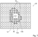
- a stabilization layer with a base area which is larger than a base area of a first layer of the print object is printed on the printing base plate.
- the stabilization layer preferably has at least partially rounded corners.
- the stabilization layer particularly preferably has an at least partially elliptical base area.
- a “stabilization layer” is to be understood in particular as a printed layer onto which a print object is printed during a printing process.
- the layer is preferably connected to the print object at least during a printing process.
- it is to be understood in particular as a layer which is provided to absorb stresses in the printed object and to dissipate them to the outside.
- the stabilization layer serves in particular to avoid warping on the print object itself, in that stresses which cause warping are diverted into the stabilization layer.
- the stabilization layer is preferably removed from the print object after a printing process. As a result, warping on the print object can advantageously be reliably avoided. In addition, a high level of control of the printing process can be achieved in particular.
- the printing base plate is actively cooled after a printing process to detach the printed object.
- the printing base plate is preferably cooled in a shock-like manner after a printing process.
- a cooling takes place in particular by means of the cooling device.
- a reliable detachment of the print object can be achieved.
- the print object has to be removed manually from the print base plate.
- an automatic detachment of the print object can thereby be achieved, even with a high level of adhesion of the print object on the printing base plate during the printing process itself.
- the 3D printing device according to the invention and the 3D printer, the printing material and the method are not intended to be restricted to the application and embodiment described above.
- the 3D printing device according to the invention and the 3D printer, the printing material and the method for fulfilling a mode of operation described herein can have a number of individual elements, components and units that differs from a number mentioned herein.
- the Figures 1 and 2 show a 3D printer with a 3D printing device 10.
- the 3D printing device 10 forms the 3D printer.
- the 3D printing device 10 is only designed as a kit which is provided for upgrading an already known 3D printer. It would therefore also be conceivable in principle that parts of the 3D printing device 10 could be assigned to the 3D printer.
- the 3D printing device 10 is designed as an FFF printing device, i. designed as a fused filament fabrication printing device.
- the 3D printing device 10 is useful as an FDM printing device, i. designed as a fused deposition modeling printing device.
- the 3D printing device 10 is intended for printing high-performance plastics.
- the 3D printing device 10 is provided for printing PAEK plastics.
- the 3D printing device 10 is used to print PEEK and / or PEKK.
- a printing material 16 is designed as a filament. Furthermore, the printing material 16 has a component which consists of PEEK and / or PEKK. Furthermore, the printing material 16 has a further component, which consists of one of PEEK and PEKK differing material. In principle, however, it would also be conceivable for the printing material 16 to consist entirely of PEEK and / or PEKK.
- the 3D printing device 10 has a frame 53.
- the frame 53 is designed as an aluminum frame.
- the frame 53 has, for example, the dimensions 350 mm in length, 560 mm in height and 350 mm in width. In principle, however, other dimensions that appear reasonable to a person skilled in the art would also be conceivable.
- the 3D printing device 10 also has a housing 54.
- the housing 54 has a plurality of plates which are fastened to the frame 53 in the form of a cover.
- the plates are made of anodized aluminum. In principle, however, another material that appears sensible to a person skilled in the art would also be conceivable.
- the housing 54 has an opening 56 on a front side, via which an installation space of the 3D printing device 10 is accessible.
- the opening 56 can be closed by a door that is not further visible.
- the door consists of a laminated safety glass.
- the installation space forms a lower level of the 3D printing device 10 ( Figure 1 ).
- a base unit 20 is located on an underside of the installation space.
- the 3D printing device 10 has the base unit 20.
- the base unit 20 has a printing base plate 22 which is printed on during a printing process.
- the pressure base plate 22 can be heated.
- the pressure base plate 22 is controllably heatable.
- the pressure base plate 22 is not further visible in segments so that it can be heated and regulated.
- a temperature of the printing base plate 22 can be regulated via a control and regulating unit 44 of the 3D printing device 10.
- the segments of the pressure base plate 22 are designed to be separately controllable.
- the segments of the printing base plate 22 can be separately heated to different degrees via the control and regulating unit 44 of the 3D printing device 10.
- the pressure base plate 22 is usually uniformly heated to 100 ° C. during operation. In principle, however, an alternative temperature control of the pressure base plate 22 would also be conceivable.
- the pressure base plate 22 has a glass plate 58 on an upper side.
- the glass plate 58 is printed on during a printing process.
- the glass plate 58 is required to allow the printing material 16, in particular the PEEK, to adhere during the printing process.
- the pressure base plate 22 is designed to be movable in the Z direction.
- the pressure base plate 22 is designed to be movable in the Z direction via a drive unit, which is not further visible.
- the drive unit of the pressure base plate 22, which is not further visible is activated by the control and regulation unit 44 of the 3D printing device 10.
- the base unit 20 also has a cooling device 24.
- the cooling device 24 is provided for active cooling of the pressure base plate 22.
- the cooling device 24 is provided for a shock-like cooling of the pressure base plate 22.
- a cooling process of the pressure base plate 22 can be controlled via the cooling device 24.
- the cooling device 24 is arranged below the pressure base plate 22.
- the cooling device 24 is designed as a water cooling device.
- cooling device 24 In order to cool the pressure base plate 22, water is circulated in the cooling device 24, which water is conducted at another point through cooling fins, which are not further visible, to give off heat. In principle, however, another configuration of the cooling device 24 that appears sensible to a person skilled in the art would also be conceivable.
- the print volume of the 3D printing device 10 is 155 mm by 155 mm by 155 mm, for example. In principle, however, another print volume that appears sensible to a person skilled in the art would also be conceivable.
- the 3D printing device 10 also has a print head unit 12.
- the print head unit 12 In an operating state, the print head unit 12 is provided to melt a printing material 16 formed from a high-performance plastic.
- the printhead unit 12 is provided in an operation to melt a printing material 16 formed from PEEK and / or PEKK.
- the print head unit 12 has a base body 46.
- the base body 46 of the print head unit 12 consists of an aluminum block.
- bearings 60, 62 for fastening an X positioning rod 64 and a Y positioning rod 66 are arranged on the base body 46.
- the print head unit 12 is connected to the frame 53 of the 3D printing device 10 via the X positioning rod 64 and the Y positioning rod 66, which cannot be seen any further.
- An XY positioning of the print head unit 12 is realized by stepping motors, which are not visible any further.
- the stepping motors which cannot be seen further, move the X-positioning rod 64 and the Y-positioning rod 66 of the print head unit 12.
- the stepping motors are each connected to the X-positioning rod 64 and the Y-positioning rod 66 via toothed belts that are not further visible.
- the stepper motors can be controlled by the control and regulation unit 44 of the 3D printing device 10.
- the print head unit 12 can be moved by the control and regulating unit 44 via the stepper motors.
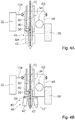
- the printhead unit 12 has a hot end 48.
- the hot end 48 is arranged on the base body 46 of the printhead unit 12.
- the hot end 48 is designed so that it can be removed separately from the base body 46.
- the hot end 48 is designed to be removable without tools.
- the hot end 48 has a nozzle 42 and a nozzle heater 68.
- the nozzle 42 of the print head unit 12 is connected to the base body 46 of the print head unit 12.
- the nozzle 42 is designed so that it can be removed separately from the base body 46.
- the nozzle 42 can be pulled downward out of the base body 46.
- the nozzle 42 is only secured against accidental falling out by a securing device, which is not further visible.
- the nozzle heater 68 is provided for heating the nozzle 42 during operation.
- the nozzle heater 68 has a 20 mm long aluminum block which is heated to approximately 340 ° C. to 400 ° C. by two resistance heating elements. The temperature is recorded and monitored by means of a thermocouple that is not visible any further.
- the aluminum block surrounds the nozzle 42. In principle, however, it would also be conceivable for the nozzle 42 to be arranged only after the nozzle heater 68 and for the printing material 16 to be melted directly in the nozzle heater 68. In principle, however, other configurations of the nozzle heater 68 that appear sensible to a person skilled in the art are also conceivable.
- a printing material 16 is directed into the nozzle 42 through a channel 70 in the base body 46 during operation in the printhead unit 12.
- the printing material 16 is melted via the nozzle heater 68 for it to be pressed out of the nozzle 42.
- the printing material 16 is melted in the area of the nozzle heater 68 and extruded through an outlet opening 72 of the nozzle 42.
- the nozzle 42 of the print head unit 12 has a hardness of at least 200 HV 10 on an inside 74.
- the nozzle 42 has a hardness of more than 2000 HV 10 on an inner side 74.
- the nozzle 42 of the print head unit 12 has a coating on an inner side 74 with a hardness of at least 200 HV 10.
- the nozzle 42 of the print head unit 12 has a coating on an inner side 74, which consists of a ceramic.
- the coating consists of tungsten carbide. In principle, however, other materials and / or coatings that appear sensible to a person skilled in the art are also conceivable for the nozzle 42 of the print head unit 12.
- a remainder of the nozzle 42 is made of brass.
- nozzle 42 of the print head unit 12 different shapes are conceivable. Three possible shapes are described below.
- the reference numbers of the various Nozzles 42, 42 ', 42 are each distinguished by apostrophes.
- the nozzles 42, 42', 42" can each be mounted on the base body 46 of the print head unit 12.
- the nozzle 42 has a short guide area 76 and a long mouth area 78.
- the mouth area 78 is divided into two sub-areas 80, 82.
- an internal pressure gauge of the nozzle 42 decreases from the guide area 76 along a main direction of extent 84 of the nozzle 42 in the direction of the outlet opening 72, with a decrease in the inside diameter in the direction of the second sub-area 82 at least approximately decreases to zero.
- an internal pressure gauge of the nozzle 42 decreases again along a main direction of extent 84 of the nozzle 42 in the direction of the outlet opening 72.
- the inside 74 of the nozzle 42 has an inner contour tapering conically towards the outlet opening 72.
- the inner contour of the outlet opening 72 of the nozzle 42 is cylindrical.
- a size of the outlet port 72 is large. This enables high printing speeds to be achieved.
- the multiple sub-areas 80, 82 of the mouth area 78 can prevent material deposits in the nozzle 42 ( Figure 5A ).
- the nozzle 42 ' has a long guide area 76' and a short mouth area 78 '.
- the guide area 76 ' has a constant inside diameter.
- Fine grooves are made on an inner side 74 'of the nozzle 42' in the guide area 76 '.
- the grooves extend parallel to a main direction of extent 84 'of the nozzle 42'.
- an advantageously high surface quality can thereby be achieved.
- an alignment of the fibers on a surface of the printing material 16 can be achieved.
- an internal pressure gauge of the nozzle 42' decreases from the guide area 76 'along a main extension direction 84' of the nozzle 42 'in the direction of the outlet opening 72'.
- the inside 74' of the nozzle 42 ' has a conical shape to the outlet opening 72 'tapering inner contour.
- the inner contour of the outlet opening 72 'of the nozzle 42' is cylindrical.
- a size of the outlet port 72 ' is small.
- the outlet opening 72 ' has a diameter of 0.4 mm. In principle, however, another diameter that appears reasonable to a person skilled in the art would also be conceivable. This enables high printing accuracy to be achieved ( Figure 5B ).
- the nozzle 42 has a long guide area 76" and a short mouth area 78 ". Furthermore, the nozzle 42" has a structural element 86 ".
- the structural element 86" is intended to generate a turbulent flow in the nozzle 42 "
- the structural element 86 " is arranged on an inner side 74" of the nozzle 42 ".
- the structural element 86 ′′ is formed by a spiral structure which guides the printing material 16 spirally through the nozzle 42 ′′ or causes a spiral movement of the printing material 16 in the nozzle 42 ′′. In principle, however, another embodiment of the would also be useful to a person skilled in the art Structural element 86 ′′ is conceivable.
- a turbulent flow in the nozzle 42 can in particular be achieved by the structural element 86".
- clogging of the outlet opening 72 ′′ can be avoided, in particular even with small outlet opening 72 ′′.
- clogging of the outlet opening 72 ′′ can be avoided when using fibers in the printing material 16 ( Figure 5C ).
- At least one of the nozzles 42, 42 ', 42 "or a further nozzle has an adjustable outlet opening 72, 72', 72". It would be particularly conceivable that a shape and / or a diameter of the outlet opening 72, 72 ', 72 "of the nozzle 42, 42', 42” can be changed. As a result, a shape and / or a diameter of the outlet opening 72, 72 ', 72 "could in particular be adapted to a current printing process. In particular, the outlet opening 72, 72', 72" of the nozzle 42, 42 ', 42 "could be adapted to current requirements, how in particular a thickness and / or a shape of a layer to be printed can be adapted.
- nozzle changing unit 45 can be mounted on the base body 46 of the print head unit 12.
- the nozzle changing unit 45 can in particular be mounted instead of a nozzle 42, 42 ', 42 ".
- the print head unit 12 has the nozzle changing unit 45.
- the nozzle changing unit 45 is designed as a nozzle turret.
- the nozzle changing unit 45 in turn has three nozzles 42, 42', 42" on. In principle, however, another number of nozzles 42, 42 ', 42 "that appears sensible to a person skilled in the art is also conceivable.
- the nozzle changing unit 45 here has, for example, the three nozzles 42, 42', 42" already described.
- the nozzle changing unit 45 generally has in particular nozzles 42, 42 ', 42 "with different diameters and / or shapes of outlet openings 72, 72', 72".
- the nozzle changing unit 45 also has a turntable 88 arranged opposite the base body 46 of the print head unit 12.
- the nozzles 42, 42 ′, 42 ′′ are arranged on a side of the rotary disk 88 facing away from the base body 46. By rotating the rotary disk 88, it is possible to manually select which nozzle 42, 42 ′, 42 ′′ is connected to the channel 70 in the base body 46 shall be.
- the nozzle changing unit 45 can be activated directly by the control and regulating unit 44 of the 3D printing device 10. In this way it could be achieved that the control and regulating unit 44 automatically selects an optimal nozzle 42, 42 ', 42 ′′ depending on a printing process. In principle, however, it would also be conceivable for the control and regulating unit 44 to be provided to an operator via a display unit that is not further visible indicates which nozzle 42, 42 ', 42 "is required for a current printing process.
- the 3D printing device 10 has a sensor unit 38 which is provided for a direct measurement of a pressure of the printing material 16 in the print head unit 12.
- the sensor unit 38 is provided for a direct measurement of a relative pressure of the printing material 16 in the printhead unit 12 relative to an ambient pressure.
- the sensor unit 38 is designed as a pressure sensor.
- the sensor unit 38 has at least one sensor element 40, which is arranged in a nozzle 42 of the print head unit 12.
- the sensor element 40 which is designed as a sensor tip and is provided for detecting a pressure, protrudes through an opening in the base body 46 and an opening in the nozzle 42 of the print head unit 12 into an interior of the nozzle 42.
- the sensor element 40 When using a nozzle exchange unit 45 the sensor element 40, which is provided for detecting a pressure, protrudes through the opening in the Base body 46 and an opening in the holder of the nozzle changing unit 45 of the print head unit 12 into an interior of the nozzle changing unit 45.
- the 3D printing device 10 has an active cooling unit 34.
- the active cooling unit 34 is designed as an active water cooling unit.
- the active cooling unit 34 is provided for active cooling of temperature-critical components.
- the active cooling unit 34 is provided to cool temperature-critical components that are in the direct vicinity of the print head unit 12.
- the active cooling unit 34 is provided, inter alia, to actively cool a sensor unit 36 arranged on the print head unit 12.
- the active cooling unit 34 is provided to cool a sensor unit 36 arranged on the print head unit 12 and designed as a measurement sensor.
- the sensor unit 36 is designed as a calibration sensor which is provided to measure the printing base plate 22 and / or a printing object 28 for a calibration but also for a real-time measurement of the printing object 28.
- the sensor unit 36 is arranged on the print head unit 12 in order to enable a movement of the sensor unit 36 without further actuators.
- the sensor unit 36 is arranged directly on the base body 46 of the print head unit 12.
- the cooling unit 34 is provided to cool the bearings 60, 62 of the X positioning rod 64 and the Y positioning rod 66.
- the active cooling unit 34 is integrated into the print head unit 12 for this purpose.
- the active cooling unit 34 has a cavity 90 in the interior of the main body 46 of the printhead unit 12. Distilled water, which is provided for cooling the bearings 60, 62 and the sensor unit 36, is conveyed into the cavity 90 via a pump, which is not further visible and is arranged outside the base body 46.
- the pump is connected to the cavity 90 via silicone hoses. The water is first conveyed through the cavity 90 and then through cooling fins, which are not further visible.
- the cooling fins are cooled by a fan.
- the cooling of the base body 46 of the printhead unit 12 also prevents the filament from melting prematurely and thus from sticking to the wall of the channel 70.
- the 3D printing device 10 has a cooling unit which is intended to provide a barrier layer between a warm and a cold area in at least one operating state, to generate a defined gas flow, in particular air flow, between the warm area and the cold area.
- the 3D printing device 10 also has a feed device 14.
- the feed device 14 is provided in at least one operation to feed a printing material 16 to the print head unit 12.
- the feed device 14 is provided to feed the printing material 16 in the form of a filament to the print head unit 12.
- the feed device 14 is arranged on a rear side of the housing 54 of the 3D printing device 10.
- the feed device 14 is designed as a Bowden extruder.
- the feed device 14 has a transport element 18.
- the transport element 18 is designed as a transport roller.
- the transport element 18 is driven by a drive unit of the feed device 14.
- the drive unit is designed as an electric motor.
- the transport element 18 is provided in at least one operating state for moving the printing material 16 at a defined feed speed.
- a printing material 16 in the form of a PEEK filament is conveyed in a defined manner via the feed device 14.
- the feed device 14 pulls the print material 16 from a print material receiving unit 92 of the 3D printing device 10.
- the printing material receiving unit 92 is also arranged on a rear side of the housing 54 of the 3D printing device 10.
- the printing material receiving unit 92 is screwed to a rear side of the housing 54.
- the printing material receiving unit 92 has a cylindrical basic shape.
- the printing material receiving unit 92 is used to rotatably accommodate a filament spool 94.
- the printing material receiving unit 92 has a cylindrical outer wall 96 which delimits the printing material 16 towards the outside in an inserted state. In the case of filaments in particular, this can prevent the printing material 16 from automatically unrolling due to its inherent tension.
- the use of the printing material 16 on a filament spool 94 is difficult. The reason for this is that the elastic energy stored in the material is so high that as soon as the material is deformed in an elastic area, it tends to return to its original shape.
- the printing material receiving unit 92 can prevent the printing material 16 from unrolling in an uncontrolled manner and possibly even becoming tangled.
- the printing material receiving unit 92 is designed for filament spools 94 with an outside diameter of 200 mm or 100 mm and with an inside diameter of not less than 43 mm. In principle, however, other dimensions that appear sensible to a person skilled in the art would also be conceivable.
- a slot 98 is arranged in the outer wall 96 of the printing material receiving unit 92.
- the slot 98 has, for example, a thickness of approximately 35 mm in width.
- the printing material 16 can be drawn out of the printing material receiving unit 92 by the feed device 14 via the slot 98.
- the feed device 14 and the printing material receiving unit 92 are arranged at a distance from one another. In this way, in particular, partial relaxation of the printing material 16 embodied as a filament can be achieved. In this way, processing can advantageously be improved.
- the alternative printing material receiving unit 92 ' also has a cylindrical basic shape.
- the alternative printing material receiving unit 92 ' is designed in the shape of a claw on an outer wall 96'.
- the printing material receiving unit 92 ′ is provided here to receive the printing material 16 directly.
- the printing material 16 is stored directly in the printing material receiving unit 92 '.
- the printing material receiving unit 92 ′ engages around the printing material 16, the printing material 16 ′, which is designed as a filament, pressing outwardly against the surrounding outer wall 96 ′ of the printing material receiving unit 92 ′ due to its internal stress.
- An additional filament spool 94 can thereby be dispensed with.
- the alternative printing material receiving unit 92 ′ can be used as an alternative to the printing material receiving unit 92.
- the 3D printing device 10 has an optional magazine 51 for receiving various printing materials 16.
- the magazine 51 is in the Figure 2 indicated by dashed lines.
- a plurality of printing material receiving units 92 are provided in the magazine 51 in particular different printing materials 16 were added.
- Different printing materials 16 are used by the 3-D printing device 10 depending on a color to be achieved and / or the strength of the printing object 28 to be printed.
- the print material 16 is conveyed from the print material receiving unit 92 to the print head unit 12 via the feed device 14.
- the pressure in the print head unit 12 is created by the printing material 16 itself, which is designed as a filament and which is conveyed by the feed device 14.
- the pressure in the print head unit 12 is controlled via the feed device 14.
- the feed device 14 is controlled by the control and regulating unit 44 of the 3D printing device 10.
- a pressure of the printing material 16 in the print head unit 12 can be reduced or increased.
- the printing material 16 is passed via an upper level located above the print head unit 12 into an interior space of the housing 54 of the 3D printing device 10 and is not further visible there, fed to the print head unit 12.
- a drying unit 50 is arranged between the feed device 14 and the print head unit 12.
- the 3D printing device 10 has the drying unit 50.
- the drying unit 50 is provided to dry the printing material 16 before it is fed to the print head unit 12.
- the drying unit 50 is provided to remove water from the printing material 16 before it is melted. The drying is no longer visible via heating elements.
- the drying process of the printing material 16 is integrated into the 3D printing device 10. In principle, however, it would also be conceivable for the printing material 16 to be dried separately before use.
- the 3D printing device 10 has at least one surface heating unit 26 arranged opposite the printing base plate 22.
- the surface heating unit 26 is provided to partially heat a printing object 28 arranged on the printing base plate 22 from a direction different from the printing base plate 22.
- the surface heating unit 26 is provided to partially heat the print object 28 from above.
- the surface heating unit 26 is provided to significantly increase a layer adhesion of the individually applied layers of printing material 16.
- the pressure base plate 22 and the surface heating unit 26 are designed to be movable relative to one another.
- the pressure base plate 22 is designed to be movable in the Z direction, whereas the surface heating unit 26 is designed to be movable in the X direction and Y direction.
- the surface heating unit 26 is arranged in a fixed position relative to the print head unit 12.
- the surface heating unit 26 is firmly connected to the at least one printhead unit 12.
- the surface heating unit 26 is moved along with the print head unit 12.
- the surface heating unit 26 is arranged in a plane 3 mm above and parallel to a printing plane of the nozzle 42 of the print head unit 12.
- the surface heating unit 26 is supplied with energy by a power supply unit which is not further visible.
- the surface heating unit 26 has a plurality of heating elements 30.
- the heating elements 30 have filaments. In principle, however, another configuration of the heating elements 30 that appears sensible to a person skilled in the art is also conceivable.
- the heating elements 30 are arranged on a mica plate 100.
- the mica plate 100 is arranged above the heating elements 30.
- the heating elements 30 are provided to heat the air layer between the print head unit 12 and the print object 28. The heat is transferred to the print object 28 via the air layer.
- the heat distribution of the printed object 28 can be improved by the additional heat.
- the temperature of this air layer is recorded and regulated by a temperature sensor that is not visible any further. In principle, however, it would also be conceivable for a temperature of the print object 28 to be monitored using a thermal imaging camera. A regulation takes place by means of the control and regulating unit 44. A partial thermal insulation towards the top can be achieved via the mica plate 100.
- the surface heating unit 26 can in particular have different geometries.
- the surface heating unit 26 is arranged in one plane so that a concentration of heat 102 occurs directly below the surface heating unit 26 ( Figure 6A ).
- a heat concentration 102 'of the surface heating unit 26' is increased in that the end areas of the surface heating unit 26 'are angled with respect to a central area ( Figure 6B ).
- the heating elements 30 of the surface heating unit 26 are designed to be controllable separately from one another. Each of the heating elements 30 is connected to a variable resistor, which is not visible any further, via which a heating output of the heating element 30 can be controlled. The heating elements 30 are activated by the control and regulation unit 44.
- the 3D printing device 10 has a local heating unit 32 which, in an operating state, is provided to partially heat a print object 28 before a further layer is printed by the print head unit 12.
- the local heating unit 32 is provided for the purpose of partially heating an uppermost print layer of the print object 28 before a further layer is imprinted by the print head unit 12 in order to improve the adhesion between the individual print layers.
- the heating by the local heating unit 32 is deliberately partially dispensed with in order to avoid deliberate adhesion.
- the local heating unit 32 is designed as a radiant heater, in particular as an infrared radiant heater.
- the local heating unit 32 is arranged on the print head unit 12.
- the local heating unit 32 is rotatably arranged around the print head unit 12.
- the local heating unit 32 is arranged on the base body 46 of the print head unit 12 via a guide system 104.
- the local heating unit 32 can be rotated relative to the print head unit 12 via the guide system 104 by means of a drive unit, which is not further visible. A rotation takes place in particular in the printing plane.
- the local heating unit 32 bypasses the print head unit 12.
- the control and regulating unit 44 controls a rotational position of the local heating unit 32.
- the control and regulating unit 44 controls a heating output of the local heating unit 32.
- the control and regulating unit 44 controls the local heating unit 32 in such a way that that the local heating unit 32 rushes the printhead unit 12 during a printing process. Rushing in advance can in turn ensure that an uppermost layer of the printed object 28 is melted on immediately before a further layer is applied.
- the 3D printing device 10 has the control and regulating unit 44.
- the control and regulation unit 44 is arranged in the upper level of the housing 54 of the 3D printing device 10.
- the control and regulation unit 44 is designed as a computing unit.
- the control and regulation unit 44 is designed as an integrated computer system.
- the control and regulation unit 44 has a touch LCD display, which is not visible any further Network connection and a USB port.
- the control and regulation unit 44 is provided for controlling and regulating pressure parameters.
- the control and regulating unit 44 is provided for controlling and regulating pressure parameters in real time.
- the control and regulating unit 44 is used to optimally adapt printing parameters to a printing process.
- the control and regulation unit 44 is provided for calculating an equation for a process quality.
- the control and regulating unit 44 is provided to, depending on a desired quality of the print object 28 and / or a desired print speed, a print speed, a temperature of the print head unit 12, a temperature of the printing base plate 22, a temperature of the print object 28 or its surroundings and / or adjust a pressure of the printing material 16 in the nozzle 42.
- the printing process is controlled and regulated by the control and regulating unit 44 of the 3D printing device 10.
- the object data of an object to be printed are transferred to the 3D printing device 10.
- the objects are transferred to the 3D printing device 10 in file formats such as .stl, .obj or .amf, which were created by CAD software.
- the object data of the object to be printed are preferably transferred to the 3D printing device 10 in a CAD file format specially developed for the 3D printing device 10.
- This special CAD file format contains additional information such as tolerances, dimensions, strength properties, etc. in a pure form.
- the CAD data is then divided into individual layers by means of a slicer software.
- the slicer software transforms the 3D model of the CAD software into a G-code of the 3D printing device 10.
- the division into layers can take place both externally and in the 3D printing device 10 itself.
- a resolution of the 3D model can be adapted to a print resolution of the 3D printing device 10.
- a shrinking process of the printed object 28 is calculated when it cools down after a printing process.
- the control and regulating unit 44 calculates a shrinkage behavior of the print object 28 as a function of a geometry of the print object 28 and fits a dimensioning of the layers of the print object 28 to this shrinkage behavior.
- the layers are in particular printed larger than the 3D model, since the print object 28 shrinks after the printing process.
- the printing routine of the individual layers is translated into machine code and sent to a microcontroller in the control and regulation unit 44.
- the software of the control and regulation unit 44 is a web-based application.
- a printing process can then be started.
- motors, the surface heating unit 26, the printing base plate 22, the active cooling unit 34, the local heating unit 32 etc. are controlled by a programmable microcontroller.
- the position information of the motors is read from the machine code by the microcontroller.
- process parameters such as temperatures of the print object 28 are displayed during the printing process.
- printing material 16 is drawn from the printing material receiving unit 92 by the feeding device 14.
- the feed device 14 conveys the printing material 16 to the print head unit 12.
- the printing material 16 is dried by means of the drying unit 50 before it is fed to the print head unit 12.
- the printing material 16 it would also be conceivable for the printing material 16 to be dried separately from a printing process.
- the printing material 16 formed by a filament is conveyed through the channel 70 of the base body 46 of the print head unit 12.
- the printing material 16 formed by a filament is actively cooled by the cooling unit 34 before it is melted.
- the printing material 16 is then conveyed into the nozzle 42 of the print head unit 12, where the printing material 16 is melted by the nozzle heater 68. After melting, the printing material 16 can be extruded through the outlet opening 72 of the nozzle 42.
- a stabilization layer 52 is printed onto the printing base plate 22.
- the stabilization layer 52 has a base area which is larger than a base area of a first layer of the printed object 28.
- the stabilization layer 52 is rounded all around and completely filled with material.
- the stabilization layer 52 has an elliptical base area. The layer is connected to the print object 28 during the printing process of the print object 28. Warping on the print object 28 can thereby be reliably avoided.
- the stabilization layer 52 is removed from the print object 28 after an entire printing process. The stabilization layer 52 is only required during the printing process.
- the print object 28 is printed directly onto the stabilization layer 52 ( Figure 10 ).
- different heating elements 30 of the surface heating unit 26 are activated as a function of parameters.
- the heating elements 30 of the surface heating unit 26 are controlled as a function of parameters of the print object 28 and parameters of the printing process.
- the heating elements 30 of the surface heating unit 26 are controlled as a function of a shape and a nature of an uppermost layer of the printed object 28.
- the heating elements 30 are controlled in such a way that precisely these heating elements 30 of the surface heating unit 26, which are located directly above the top layer of the printed object 28, are activated. This can prevent the top layer from cooling down.
- the shape of the top layer of the print object 28 is stylized by the line 106, whereas activated heating elements 30 of the surface heating unit 26 are shown by wavy hatching. Furthermore, partial areas of the print object 28 are heated in a targeted manner by controlling different heating elements 30 of the surface heating unit 26. If, by means of the temperature sensor, which is not further visible, it is determined that areas of the already printed sub-area of the printed object 28 are cooling too much, heating elements 30 are controlled in an increased manner over these areas in order to avoid further cooling.
- the print object 28 is partially heated by the local heating unit 32 before a further layer is printed on. In the process, an uppermost, already printed layer of the print object 28 is melted.
- the local heating unit 32 is arranged by the control and regulating unit 44 continuously in front of the print head unit 12 in the direction of movement of the print head unit 12 during the printing process. In this way, a targeted fusion of layers can be achieved.
- the print object 28 is partially measured during the printing process.
- the print object 28 is measured during the printing process by means of the sensor unit 36, which is designed as a calibration sensor.
- the print object 28 is measured during the printing process to identify possible deviations between the print object 28 and to determine a 3D model stored on the control and regulation unit 44.
- printing parameters of the printing process are partially adapted.
- the printing parameters of a printing process are adapted as a function of a deviation between the print object 28 and the 3D model stored on the control and regulation unit 44.
- the 3D printing device 10 can automatically carry out subsequent improvements to the print object 28 as a function of a measurement result. If, in the case of a measurement result, significant deviations occur between the print object 28 and a 3D model stored on the control and regulation unit 44, subsequent improvements can be carried out in a targeted manner in order to improve the deviations.
- the 3D printing device 10 has an integrated material test system, so that the strength properties of the printed object 28 can be checked during or after the printing process.
- control and regulating unit 44 constantly adjusts printing parameters during the printing process.
- the control and regulation unit 44 optimally adapts the printing parameters to a printing process.
- the control and regulation unit 44 calculates an equation for a process quality.
- the equation is used to calculate a required print speed, temperature of print head unit 12, temperature of print base plate 22, temperature of print object 28 or its surroundings and a required pressure of print material 16 in nozzle 42 depending on a desired quality of print object 28 and a desired print speed .
- the calculated printing speed, temperature of the print head unit 12, temperature of the printing base plate 22, temperature of the print object 28 or its surroundings and the calculated pressure of the printing material 16 in the nozzle 42 are then set by the control and regulating unit 44.
- a printing speed is thus set as a function of a printing of the printing material 16 in the print head unit 12. That in the Figure 9
- the diagram shown shows, in a simplified manner, a relationship between the printing parameters of the 3D printing device 10.
- the diagram shows a relationship between the nozzle temperature T D , the quality Q p of the print object 28 and the printing speed v p .
- the diagram also shows a first curve 108, which represents a direct relationship between the nozzle temperature T D and the quality Q p of the printed object 28, and a second curve 110, which represents a direct relationship between the printing speed v p and the quality Q p of the printed object 28.
- a color of a print object 28 to be printed is also influenced by adapting print parameters.
- a color of a print object 28 to be printed is influenced by adjusting a print temperature and a pressure of the print material 16 in the print head unit 12.
- the control and regulating unit 44 therefore adjusts a printing temperature and a pressure of the printing material 16 as a function of a desired color of the print object 28.
- other printing parameters that appear sensible to a person skilled in the art are also conceivable for adapting a color of a print object 28 to be printed.
- the printing base plate 22 is actively cooled in order to detach the printing object 28.
- the pressure base plate 22 is cooled via the cooling device 24. Due to the different thermal expansion coefficients of the printing base plate 22 and the printing object 28, an adhesion between the printing base plate 22 and the printing object 28 is released.
- the printing object 28 can then be removed from the 3D printing device 10 via the opening 56 in the housing 54.
Landscapes
- Chemical & Material Sciences (AREA)
- Engineering & Computer Science (AREA)
- Materials Engineering (AREA)
- Manufacturing & Machinery (AREA)
- Physics & Mathematics (AREA)
- Mechanical Engineering (AREA)
- Optics & Photonics (AREA)
- Ink Jet (AREA)
Description
Die Erfindung betrifft eine 3D-Druckvorrichtung.The invention relates to a 3D printing device.
In diesem Zusammenhang ist aus der
Außerdem ist aus der
Außerdem ist aus der
Aus der
Aus der
Auch aus der
Die Aufgabe der Erfindung besteht insbesondere darin, eine gattungsgemäße Vorrichtung mit verbesserten Eigenschaften hinsichtlich der Verarbeitbarkeit technischer Kunststoffe bereitzustellen. Die Aufgabe wird erfindungsgemäß durch die Merkmale des Patentanspruchs 1 gelöst, während vorteilhafte Ausgestaltungen und Weiterbildungen der Erfindung den Unteransprüchen entnommen werden können.The object of the invention is in particular to provide a device of the generic type with improved properties with regard to the processability of engineering plastics. The object is achieved according to the invention by the features of claim 1, while advantageous configurations and developments of the invention can be found in the subclaims.
Die Erfindung geht aus von einer 3D-Druckvorrichtung, insbesondere von einer FFF-Druckvorrichtung, mit zumindest einer Druckkopfeinheit und mit zumindest einer Zuführvorrichtung, welche in zumindest einem Betriebszustand dazu vorgesehen ist, der zumindest einen Druckkopfeinheit ein Druckmaterial zuzuführen.The invention is based on a 3D printing device, in particular an FFF printing device, with at least one print head unit and with at least one feed device, which is provided in at least one operating state to supply a printing material to the at least one print head unit.
Es wird vorgeschlagen, dass die Druckkopfeinheit in zumindest einem Betriebszustand dazu vorgesehen ist, ein zumindest teilweise von einem Hochleistungskunststoff, insbesondere einem Hochleistungsthermoplast, gebildetes Druckmaterial aufzuschmelzen. Vorzugsweise ist die Druckkopfeinheit in zumindest einem Betriebszustand dazu vorgesehen, ein zumindest teilweise von einem PAEK, besonders bevorzugt von einem PEEK und/oder PEKK, gebildetes Druckmaterial aufzuschmelzen. Unter einer "3D-Druckvorrichtung" soll in diesem Zusammenhang insbesondere eine Vorrichtung verstanden werden, die zu einem dreidimensionalen Aufbau eines Werkstücks vorgesehen ist. Vorzugsweise soll darunter insbesondere eine Vorrichtung verstanden werden, die zu einem, insbesondere schichtweisen Aufbau eines Werkstücks aus einem Werkstoff vorgesehen ist. Ein Aufbau des Werkstücks erfolgt dabei insbesondere additiv. Besonders bevorzugt soll darunter insbesondere eine computergesteuerte Vorrichtung verstanden werden, welche zu einer Herstellung eines individuellen Werkstücks, insbesondere gemäß einer CAD-Vorlage, vorgesehen ist. Ein Werkstück wird dabei insbesondere durch Aufschmelzen eines Werkstoffs aufgebaut. Ferner soll in diesem Zusammenhang unter einer FFF-Druckvorrichtung insbesondere eine 3D-Druckvorrichtung verstanden werden, bei welcher ein Werkstück mittels "Fused Filament Fabrication", insbesondere mittels "Fused Deposition Modeling" aufgebaut wird. "Fused Filament Fabrication" beschreibt dabei insbesondere ein Fertigungsverfahren aus dem Bereich des Rapid Prototyping, bei dem ein Werkstück schichtweise aus einem Werkstoff, insbesondere aus einem Kunststoff, besonders bevorzugt aus einem Filament, aufgebaut wird.It is proposed that the print head unit is provided in at least one operating state to melt a printing material formed at least partially from a high-performance plastic, in particular a high-performance thermoplastic. In at least one operating state, the print head unit is preferably provided to melt a printing material formed at least partially from a PAEK, particularly preferably from a PEEK and / or PEKK. In this context, a “3D printing device” is to be understood in particular as a device which is provided for a three-dimensional structure of a workpiece. Preferably, this should be understood to mean, in particular, a device which is provided for building a workpiece, in particular in layers, from a material. The workpiece is built up in particular additively. Particularly preferably, it is to be understood in particular as a computer-controlled device which is provided for the production of an individual workpiece, in particular according to a CAD template. A workpiece is built up by melting a material. Furthermore, in this context, an FFF printing device is to be understood in particular as a 3D printing device in which a workpiece is built up by means of “fused filament fabrication”, in particular by means of “fused deposition modeling”. "Fused Filament Fabrication" describes in particular a manufacturing method from the field of rapid prototyping, in which a workpiece is built up in layers from a material, in particular from a plastic, particularly preferably from a filament.
Des Weiteren soll in diesem Zusammenhang unter einer "Druckkopfeinheit", insbesondere eine vorzugsweise bewegliche Einheit der 3D-Druckvorrichtung verstanden werden, über welche in einem Betrieb direkt Druckmaterial auf eine Druckfläche aufgebracht wird. Vorzugsweise weist die Druckkopfeinheit zumindest eine Düse auf, über welche ein Druckmaterial ausgebracht, insbesondere extrudiert, wird.Furthermore, in this context, a “print head unit”, in particular a preferably movable unit of the 3D printing device, is to be understood through which printing material is applied directly to a printing surface in an operation. The print head unit preferably has at least one nozzle via which a printing material is applied, in particular extruded.
Unter einer "Zuführvorrichtung" soll in diesem Zusammenhang insbesondere eine Vorrichtung verstanden werden, die dazu vorgesehen ist, der Druckkopfeinheit während eines Betriebs ein Druckmaterial zuzuführen. Vorzugsweise ist die Zuführvorrichtung zu einer Bereitstellung eines Druckmaterials an der Druckkopfeinheit vorgesehen. Bevorzugt soll darunter insbesondere eine Vorrichtung verstanden werden, die dazu vorgesehen ist, ein Druckmaterial aus einem Speicher zu der Druckkopfeinheit zu transportieren. Ein Transport erfolgt dabei insbesondere in einer definierten Menge und/oder mit einer definierten Vorschubgeschwindigkeit. Unter "vorgesehen" soll insbesondere speziell programmiert, ausgelegt und/oder ausgestattet verstanden werden. Darunter, dass ein Objekt zu einer bestimmten Funktion vorgesehen ist, soll insbesondere verstanden werden, dass das Objekt diese bestimmte Funktion in zumindest einem Anwendungs- und/oder Betriebszustand erfüllt und/oder ausführt. Unter einem "Hochleistungskunstoff" soll in diesem Zusammenhang insbesondere ein Kunststoff, vorzugsweise ein Thermoplast, verstanden werden, der eine Wärmeformbeständigkeit von mehr als 150 °C aufweist. Es sind verschiedene, einem Fachmann als sinnvoll erscheinende Hochleistungskunststoffe denkbar, wie beispielsweise Polyaryle, Polyarylate, Polyaramide, Heterocyclische Polymere, Flüssigkristallpolymere und/oder Polyaryletherketone. Ferner soll unter "PAEK" insbesondere die Gruppe der Polyaryletherketone verstanden werden, zu welcher beispielsweise PEEK, PEK, PEKEKK und PEKK gehören.In this context, a “feed device” is to be understood in particular as a device which is provided to feed a printing material to the print head unit during operation. The feed device is preferably provided for providing a printing material on the print head unit. Preferred should this is understood to mean in particular a device which is provided to transport a printing material from a memory to the print head unit. A transport takes place in particular in a defined amount and / or at a defined feed rate. “Provided” is to be understood in particular as specifically programmed, designed and / or equipped. The fact that an object is provided for a specific function should be understood in particular to mean that the object fulfills and / or executes this specific function in at least one application and / or operating state. In this context, a "high-performance plastic" is to be understood in particular as a plastic, preferably a thermoplastic, which has a heat resistance of more than 150.degree. Various high-performance plastics that appear sensible to a person skilled in the art are conceivable, such as, for example, polyaryls, polyarylates, polyaramides, heterocyclic polymers, liquid crystal polymers and / or polyaryletherketones. Furthermore, “PAEK” is to be understood in particular as the group of polyaryl ether ketones, to which, for example, PEEK, PEK, PEKEKK and PEKK belong.
Durch die erfindungsgemäße Ausgestaltung der 3D-Druckvorrichtung kann insbesondere eine Druckvorrichtung bereitgestellt werden, mittels welcher zumindest Hochleistungskunststoffe, insbesondere Hochleistungsthermoplasten, verarbeitet werden können. Dadurch kann insbesondere erreicht werden, dass auch technische Bauteile und Bauteile, welche einer hohen thermischen Belastung ausgesetzt sind, mittels einer 3D-Druckvorrrichtung hergestellt werden können.The inventive design of the 3D printing device can in particular provide a printing device by means of which at least high-performance plastics, in particular high-performance thermoplastics, can be processed. In this way, it can be achieved in particular that technical components and components that are exposed to high thermal loads can also be produced by means of a 3D printing device.
Ferner wird vorgeschlagen, dass die 3D-Druckvorrichtung als eine 3D-Dentaldruckvor-richtung ausgebildet ist. Vorzugsweise kann die 3D-Druckvorrichtung zu einer Herstellung von Dentalobjekten, insbesondere zur Herstellung von dentalen Implantaten, Provisorien, Inlays und/oder Zahnersatz, verwendet werden. Unter einer "3D-Dentaldruckvor-richtung" soll in diesem Zusammenhang insbesondere eine 3D-Druck-vorrichtung verstanden werden, die zu einer Herstellung von Elementen im dentalen Bereich, insbesondere von Dentalobjekten wie beispielsweise Halbzeugen, Zwischenprodukten und/oder Endprodukten vorgesehen ist. Dadurch kann eine vorteilhafte Ausgestaltung der 3D-Druckvorrichtung bereitgestellt werden. Grundsätzlich sind jedoch auch anderen, einem Fachmann als sinnvoll erscheinende Anwendungen der 3D-Druckvorrichtung denkbar.It is also proposed that the 3D printing device be designed as a 3D dental printing device. The 3D printing device can preferably be used to produce dental objects, in particular for the production of dental implants, temporaries, inlays and / or dentures. In this context, a "3D dental printing device" is to be understood as meaning, in particular, a 3D printing device that is provided for the production of elements in the dental field, in particular of dental objects such as semi-finished products, intermediate products and / or end products. As a result, an advantageous embodiment of the 3D printing device can be provided. In principle, however, other applications of the 3D printing device that appear sensible to a person skilled in the art are also conceivable.
Insbesondere kann dadurch erreicht werden, dass Dentalobjekte, insbesondere individuelle Dentalobjekte, vorteilhaft schnell und einfach hergestellt werden können.In particular, it can thereby be achieved that dental objects, in particular individual dental objects, can advantageously be produced quickly and easily.
Ferner wäre dabei zudem denkbar, dass die 3D-Druckvorrichtung zu einer Herstellung von Dentalobjekten, insbesondere zur Herstellung von dentalen Implantaten, Provisorien, Inlays und/oder Zahnersatz, dazu vorgesehen ist, ein Druckmaterial auf eine individuell dreidimensional geformte Druckfläche aufzubringen. Vorzugsweise ist die Druckfläche dabei von einem dentalen Positivabdruckmodell gebildet. Dadurch kann ein Dentalobjekt insbesondere direkt auf ein Abbild eines Gebisses des Patienten gedruckt werden. Bei einem Druck kann dadurch insbesondere die Verwendung von Stützmaterial vermieden werden. Ferner kann dadurch ein Druck insbesondere vorteilhaft schnell realisiert werden. Eine entsprechende mögliche Realisierung kann der deutschen Offenlegungsschrift
Es wird weiter vorgeschlagen, dass die 3D-Druckvorrichtung eine Grundeinheit mit zumindest einer beheizbaren, insbesondere regelbar beheizbaren, Druckgrundplatte aufweist, auf welche während eines Druckvorgangs aufgedruckt wird. Vorzugsweise ist die Druckgrundplatte in Segmenten regelbar beheizbar. Bevorzugt sind die Segmente der Druckgrundplatte separat ansteuerbar ausgebildet. Besonders bevorzugt sind die Segmente der Druckgrundplatte über eine Steuer- und/oder Regeleinheit separat ansteuerbar. Bevorzugt kann die Druckgrundplatte so über die Steuer- und/oder Regeleinheit unterschiedlich stark erhitzt werden. Hierdurch kann insbesondere eine gezielte Erhitzung erreicht werden. Ferner kann dadurch eine vorteilhaft effiziente Druckgrundplatte erreicht werden. Unter einer "Druckgrundplatte" soll in diesem Zusammenhang insbesondere ein Element oder eine Einheit verstanden werden, das oder die zumindest teilweise einen Untergrund für einen Druck bildet. Vorzugsweise soll darunter insbesondere ein Element oder eine Einheit verstanden werden, auf welchem oder welcher ein zu druckendes Objekt aufgebaut wird. Vorzugsweise wird eine erste Schicht eines Druckobjekts direkt auf die Druckgrundplatte aufgebaut. Bevorzugt ist die Druckgrundplatte von einer rechteckigen insbesondere ebenen Platte gebildet, auf welche während eines Drucks aufgedruckt wird. Grundsätzlich wäre jedoch auch eine unebene, wie beispielsweise gebogene Form der Platte denkbar. Bevorzugt ist eine Temperatur der Druckgrundplatte zumindest steuerbar, besonders bevorzugt regelbar. Dadurch kann vorteilhaft ein zu druckendes Objekt von einer Basis her erwärmt werden. Hierdurch kann ein zu schnelles Abkühlen eines zu druckenden Objekts vermieden werden.It is further proposed that the 3D printing device has a base unit with at least one heatable, in particular controllably heatable, printing base plate on which printing is carried out during a printing process. The pressure base plate can preferably be heated in a controllable manner in segments. The segments of the pressure base plate are preferably designed to be separately controllable. Particularly preferably, the segments of the pressure base plate can be controlled separately via a control and / or regulating unit. The pressure base plate can preferably be heated to different degrees in this way via the control and / or regulating unit. In this way, in particular, targeted heating can be achieved. Furthermore, an advantageously efficient printing base plate can thereby be achieved. In this context, a “printing base plate” is to be understood as meaning in particular an element or a unit which at least partially forms a background for a print. Preferably, this is to be understood in particular as an element or a unit on which an object to be printed is built. A first layer of a print object is preferably built up directly on the print base plate. The printing base plate is preferably formed by a rectangular, in particular flat, plate on which printing is carried out during printing. In principle, however, an uneven, such as a curved shape of the plate would also be conceivable. A temperature of the pressure base plate is preferably at least controllable, particularly preferably regulatable. This allows an object to be printed to be advantageous be heated from a base. This can prevent an object to be printed from cooling down too quickly.
Ferner wird vorgeschlagen, dass die 3D-Druckvorrichtung zumindest eine gegenüber der Druckgrundplatte angeordnete Flächenheizungseinheit aufweist, welche dazu vorgesehen ist, ein auf der Druckgrundplatte angeordnetes Druckobjekt aus einer von der Druckgrundplatte differierenden Richtung zumindest partiell zu erhitzen. Vorzugsweise ist die Flächenheizungseinheit dazu vorgesehen, ein Druckobjekt von einer Seite und/oder besonders bevorzugt von oben zumindest partiell zu erhitzen. Darunter, dass "die Flächenheizungseinheit gegenüber der Druckgrundplatte angeordnet ist", soll in diesem Zusammenhang insbesondere verstanden werden, dass zwischen der Druckgrundplatte und der Flächenheizungseinheit zumindest teilweise der Druckbereich angeordnet ist, in welchem ein Druckobjekt während eines Betriebs der 3D-Druckvorrichtung aufgebaut wird. Vorzugsweise soll darunter insbesondere verstanden werden, dass die Flächenheizungseinheit zumindest teilweise in einem Bereich angeordnet ist, der sich senkrecht zu einer Druckfläche der Druckgrundplatte nach oben erstreckt. Ferner soll in diesem Zusammenhang unter einer "Flächenheizungseinheit" insbesondere eine Einheit verstanden werden, die zumindest teilweise zu einer flächigen Erzeugung einer Heizleistung vorgesehen ist. Vorzugsweise wird eine Heizleistung auf einer Fläche von zumindest 10 cm2, vorzugsweise von zumindest 50 cm2 und besonders bevorzugt von zumindest 100 cm2 erzeugt. Bevorzugt soll darunter eine Einheit verstanden werden, die zu einer Erzeugung einer flächigen Heizstrahlung vorgesehen ist. Besonders bevorzugt ist eine Heizstrahlung dabei zumindest im Wesentlichen senkrecht zu einer Fläche der Flächenheizungseinheit ausgerichtet. Grundsätzlich sind jedoch auch andere, einem Fachmann als sinnvoll erscheinende Ausgestaltungen der Flächenheizungseinheit denkbar. Grundsätzlich wäre auch denkbar, dass die Flächenheizungseinheit als eine Mikrowellenheizeinheit ausgebildet ist, welche zu einer gezielten Aussendung von Mikrowellen zu einer partiellen Erhitzung des Druckobjekts vorgesehen ist. Darunter, dass "die Flächenheizungseinheit dazu vorgesehen ist, ein Druckobjekt partiell zu erhitzen", soll in diesem Zusammenhang insbesondere verstanden werden, dass die Flächenheizungseinheit dazu vorgesehen ist, zumindest Teilbereiche eines bereits gedruckten Teils des Druckobjekts zu erhitzen. Vorzugsweise ist die Flächenheizungseinheit dazu vorgesehen, einen Teilbereich des Druckobjekts gezielt gegenüber einem differierenden Teilbereich zu erhitzen.It is further proposed that the 3D printing device has at least one surface heating unit arranged opposite the printing base plate, which is provided to at least partially heat a printing object arranged on the printing base plate from a direction different from the printing base plate. The surface heating unit is preferably provided to at least partially heat a print object from one side and / or particularly preferably from above. The fact that “the surface heating unit is arranged opposite the printing base plate” is to be understood in this context in particular as the printing area in which a print object is built up during operation of the 3D printing device is at least partially arranged between the printing base plate and the surface heating unit. Preferably, this is to be understood in particular as meaning that the surface heating unit is arranged at least partially in an area which extends upwards perpendicular to a pressure surface of the pressure base plate. Furthermore, in this context, a “surface heating unit” is to be understood as meaning, in particular, a unit which is provided at least partially for the planar generation of heating power. A heating power is preferably generated over an area of at least 10 cm 2 , preferably of at least 50 cm 2 and particularly preferably of at least 100 cm 2 . Preferably, this is to be understood as a unit which is provided for the generation of planar heating radiation. In this case, heating radiation is particularly preferably aligned at least substantially perpendicular to a surface of the surface heating unit. In principle, however, other configurations of the surface heating unit that appear sensible to a person skilled in the art are also conceivable. In principle, it would also be conceivable for the surface heating unit to be designed as a microwave heating unit, which is provided for targeted emission of microwaves for partial heating of the printed object. The fact that “the surface heating unit is provided to partially heat a print object” is to be understood in this context in particular as meaning that the surface heating unit is provided to heat at least partial areas of an already printed part of the print object. The surface heating unit is preferably provided to specifically heat a sub-area of the print object in relation to a different sub-area.
Dabei kann unter "erhitzen" jedoch auch lediglich das Halten einer Temperatur des Teilbereichs und/oder das Verhindern eines schnellen Absinkens einer Temperatur des Teilbereichs verstanden werden. Dadurch kann vorteilhaft eine Temperatur des Druckobjekts gezielt beeinflusst werden. Vorzugsweise kann dadurch vorteilhaft eine Temperatur des Druckobjekts an einen Druckprozess angepasst werden. Insbesondere kann dadurch gezielt die Temperatur einzelner Teilbereiche des Druckobjekts gesteuert werden. Insbesondere kann dadurch eine vorteilhaft gleichmäßige Wärmeverteilung des Druckobjekts auch in einer Druckkammer erreicht werden. Vorzugsweise kann dadurch verhindert werden, dass Temperaturdifferenzen auftreten, welche zu einer Verformung des Druckobjekts führen. Ferner können makroskopische Deformationen des Druckobjekts unterdrückt werden, indem ein Erstarrungsprozess gezielt gesteuert wird. Zudem kann eine homogene Farbe des Druckobjekts, insbesondere ähnlich einer Ausgangsfarbe des Druckmaterials, erreicht werden. Insbesondere können vorteilhafte mechanische Eigenschaften des Druckobjekts erreicht werden.In this context, however, “heating” can also be understood to mean merely maintaining a temperature of the sub-area and / or preventing a rapid drop in a temperature of the sub-area. As a result, a temperature of the print object can advantageously be influenced in a targeted manner. A temperature of the print object can thereby advantageously be adapted to a printing process. In particular, the temperature of individual subregions of the print object can thereby be controlled in a targeted manner. In particular, an advantageously uniform heat distribution of the print object can also be achieved in a pressure chamber. This can preferably prevent temperature differences from occurring, which lead to a deformation of the printed object. Furthermore, macroscopic deformations of the printed object can be suppressed by specifically controlling a solidification process. In addition, a homogeneous color of the print object, in particular similar to an initial color of the print material, can be achieved. In particular, advantageous mechanical properties of the print object can be achieved.
Des Weiteren wird vorgeschlagen, dass die zumindest eine Druckgrundplatte und die zumindest eine Flächenheizungseinheit relativ zueinander beweglich ausgeführt sind. Vorzugsweise ist die Flächenheizungseinheit relativ zu der Druckgrundplatte beweglich ausgeführt. Besonders bevorzugt ist die Flächenheizungseinheit relativ zu der Druckgrundplatte und die Druckgrundplatte relativ zu der Flächenheizungseinheit beweglich ausgeführt. Vorzugsweise ist die Flächenheizungseinheit relativ zu der Druckkopfeinheit positionsfest angeordnet. Es wäre jedoch auch denkbar, dass die Flächenheizungseinheit unabhängig von der Druckkopfeinheit beweglich ausgeführt ist. Besonders bevorzugt ist die Flächenheizungseinheit jedoch fest mit der Druckkopfeinheit verbunden. Dadurch kann eine Erhitzung des Druckobjekts durch die Flächenheizungseinheit, insbesondere unabhängig von einer Position der Druckgrundplatte erfolgen. Bei einer positionsfesten Anordnung der Flächenheizungseinheit relativ zu der Druckkopfeinheit kann insbesondere vermieden werden, dass eine Bewegung der Druckkopfeinheit eine Heizwirkung der Flächenheizungseinheit, insbesondere durch ein Verdecken, negativ beeinflusst. Insbesondere kann dadurch eine vorteilhaft flächige Flächenheizungseinheit realisiert werden.It is further proposed that the at least one pressure base plate and the at least one surface heating unit are designed to be movable relative to one another. The surface heating unit is preferably designed to be movable relative to the pressure base plate. It is particularly preferable for the surface heating unit to be designed to be movable relative to the pressure base plate and the pressure base plate to be movable relative to the surface heating unit. The surface heating unit is preferably arranged in a fixed position relative to the print head unit. However, it would also be conceivable for the surface heating unit to be designed to be movable independently of the print head unit. Particularly preferably, however, the surface heating unit is firmly connected to the print head unit. As a result, the printing object can be heated by the surface heating unit, in particular independently of a position of the printing base plate. If the surface heating unit is arranged in a fixed position relative to the print head unit, it can in particular be avoided that a movement of the print head unit negatively influences a heating effect of the surface heating unit, in particular by being covered. In particular, an advantageously flat surface heating unit can thereby be implemented.
Des Weiteren wird vorgeschlagen, dass die Zuführvorrichtung dazu vorgesehen ist, das Druckmaterial in Form eines Filaments der Druckkopfeinheit zuzuführen.It is also proposed that the feed device is provided to feed the printing material in the form of a filament to the print head unit.
Unter einem "Filament" soll in diesem Zusammenhang insbesondere ein faden- und/oder stabförmig vorliegender Werkstoff verstanden werden. Vorzugsweise soll darunter insbesondere ein Werkstoff, insbesondere ein Kunststoff, verstanden werden, der in einer fadenähnlichen Form vorliegt, daher insbesondere eine Quererstreckung aufweist, die um ein Vielfaches geringer ist als eine Längserstreckung entlang einer Mittelfaser. Vorzugsweise beträgt eine Quererstreckung weniger als 1,5cm, vorzugsweise weniger als 1cm und besonders bevorzugt weniger als 0,5cm. Bevorzugt weist das Filament einen zumindest annähernd runden Querschnitt auf. Besonders bevorzugt liegt das Filament in einer auf einer Spule aufgewickelten Form vor. Dabei soll unter "um ein Vielfaches geringer" insbesondere zumindest 10-mal, vorzugsweise zumindest 50-mal und besonders bevorzugt zumindest 100-mal geringer verstanden werden. Grundsätzlich muss jedoch berücksichtigt werden, dass sich eine Längserstreckung des Filaments entlang der Mittelfaser vorzugsweise während eines Betriebs der 3D-Druckvorrichtung verringert, sodass ein Verhältnis der Quererstreckung zu einer Längserstreckung vorzugsweise auf einen Ursprungszustand bezogen ist. Dadurch kann insbesondere eine besonders vorteilhafte Zuführung erreicht werden. Vorzugsweise kann dadurch vorteilhaft konstruktiv einfach eine Zuführmenge und/oder eine Zuführgeschwindigkeit gesteuert werden. Ferner kann dadurch vorteilhaft schnell ein Aufschmelzen des Druckmaterials erreicht werden.In this context, a “filament” is to be understood in particular as a material in the form of a thread and / or rod. Preferably, this should be understood to mean, in particular, a material, in particular a plastic, which is present in a thread-like form, therefore in particular has a transverse extent that is many times smaller than a longitudinal extent along a central fiber. A transverse extension is preferably less than 1.5 cm, preferably less than 1 cm and particularly preferably less than 0.5 cm. The filament preferably has an at least approximately round cross section. Most preferably, the filament is in a form wound on a spool. In this context, “many times less” should be understood to mean in particular at least 10 times, preferably at least 50 times and particularly preferably at least 100 times less. In principle, however, it must be taken into account that a longitudinal extension of the filament along the central fiber preferably decreases during operation of the 3D printing device, so that a ratio of the transverse extension to a longitudinal extension is preferably based on an original state. In particular, a particularly advantageous feed can thereby be achieved. A feed quantity and / or a feed speed can thereby advantageously be controlled in a structurally simple manner. Furthermore, a melting of the printing material can thereby advantageously be achieved quickly.
Es wird ferner vorgeschlagen, dass die Zuführvorrichtung zumindest ein Transportelement aufweist, das in zumindest einem Betriebszustand zu einer Bewegung des Druckmaterials mit einer definierten Vorschubgeschwindigkeit vorgesehen ist. Vorzugsweise ist das Transportelement zumindest teilweise als eine Transportrolle ausgebildet. Besonders bevorzugt kann über die Vorschubgeschwindigkeit der Zuführvorrichtung eine Zuführmenge von Druckmaterial eingestellt werden. Unter einem "Transportelement" soll in diesem Zusammenhang insbesondere ein Element der Zuführvorrichtung verstanden werden, welches zu einem direkten Transport des Druckmaterials vorgesehen ist. Vorzugsweise soll darunter ein Element verstanden werden, das zu einer Bereitstellung eines Vorschubs des Druckmaterials in Richtung der Druckkopfeinheit vorgesehen ist. Besonders bevorzugt ist das Transportelement dazu vorgesehen, das Druckmaterial, insbesondere in Form eines Filaments, aus einem Speicher, insbesondere einer Spule, zu ziehen und zu der Druckkopfeinheit zu fördern. Vorzugsweise ist das Transportelement zu einer Bereitstellung eines Druckmaterials an der Druckkopfeinheit vorgesehen. Dadurch kann zuverlässig eine Zufuhr von Druckmaterial gewährleistet werden. Ferner kann dadurch insbesondere eine Menge eines zugeführten Druckmaterials beeinflusst werden. Es kann ein zuverlässiger Druckprozess gewährleistet werden.It is further proposed that the feed device has at least one transport element which, in at least one operating state, is provided for moving the printing material at a defined feed rate. The transport element is preferably designed at least partially as a transport roller. Particularly preferably, a feed quantity of printing material can be set via the feed speed of the feed device. In this context, a “transport element” is to be understood in particular as an element of the feed device which is provided for direct transport of the printing material. Preferably, this is to be understood as an element which is provided for providing a feed of the printing material in the direction of the print head unit. The transport element is particularly preferably provided to pull the printing material, in particular in the form of a filament, from a storage device, in particular a spool, and to convey it to the print head unit. The transport element is preferably provided for providing a printing material on the print head unit. This ensures that printing material is reliably fed. Furthermore, in particular the amount of media being fed can be affected. A reliable printing process can be guaranteed.
Zudem wird vorgeschlagen, dass die Grundeinheit zumindest eine Kühlvorrichtung aufweist, die zu einer aktiven Abkühlung der Druckgrundplatte vorgesehen ist. Vorzugsweise ist die Kühlvorrichtung zu einer schockartigen Abkühlung der Druckgrundplatte vorgesehen. Bevorzugt kann über die Kühlvorrichtung ein Abkühlverlauf der Druckgrundplatte zumindest beeinflusst, besonders bevorzugt gesteuert werden. Unter einer "Kühlvorrichtung" soll in diesem Zusammenhang insbesondere eine Vorrichtung verstanden werden, welche zu einer aktiven Kühlung der Druckgrundplatte vorgesehen ist. Vorzugsweise soll darunter eine Vorrichtung verstanden werden, die, insbesondere nach einer Deaktivierung einer Beheizung der Druckgrundplatte, zu einer aktiven Senkung einer Temperatur der Druckgrundplatte vorgesehen ist. Eine Kühlung geht dabei insbesondere über eine reine Wärmeabgabe an eine Umgebung hinaus. Es sind dabei verschiedene, einem Fachmann als sinnvoll erscheinende Methoden zu einer Kühlung denkbar, wie insbesondere eine Flüssigkeitskühlung, wie beispielsweise eine Wasser- oder Ölkühlung, und/oder eine Gaskühlung, wie beispielsweise Luft- oder Kohlenstoffkühlung. Dadurch kann vorteilhaft ein schnelles Abkühlen der Druckgrundplatte erreicht werden. Insbesondere kann dadurch aktiv ein Abkühlverlauf der Kühlvorrichtung beeinflusst, insbesondere gesteuert werden. Dadurch kann insbesondere beispielsweise ein Ablösen eines Druckobjekts erreicht werden. Ferner kann dadurch beispielsweise ein "Warping" des Druckobjekts durch eine falsche Abkühlung vermieden werden. Ein Abkühlverlauf kann vorteilhaft an ein Druckobjekt angepasst werden. Dabei soll unter "Warping" insbesondere ein Verziehen des Druckobjekts nach einem Druck verstanden werden. Das Warping entsteht insbesondere aufgrund von ungleichmäßig verteilten Eigenspannungen im Filament als Folge unterschiedlicher Abkühlgeschwindigkeiten und -temperaturen der einzelnen Schichten. Insbesondere wird das Warping durch die Schrumpfung des Kunststoffs während des Abkühlvorgangs verursacht.It is also proposed that the base unit have at least one cooling device which is provided for actively cooling the pressure base plate. The cooling device is preferably provided for a shock-like cooling of the pressure base plate. A cooling process of the pressure base plate can preferably be at least influenced, particularly preferably controlled, via the cooling device. In this context, a “cooling device” is to be understood in particular as a device which is provided for active cooling of the printing base plate. It is preferably to be understood as a device which, in particular after deactivation of a heating of the printing base plate, is provided for an active lowering of a temperature of the printing base plate. In particular, cooling goes beyond a pure heat release to an environment. Various cooling methods that appear sensible to a person skilled in the art are conceivable, in particular liquid cooling, such as water or oil cooling, and / or gas cooling, such as air or carbon cooling. Rapid cooling of the printing base plate can thereby advantageously be achieved. In particular, a cooling process of the cooling device can thereby be actively influenced, in particular controlled. In this way, for example, a printing object can be detached. Furthermore, "warping" of the print object due to incorrect cooling can thereby be avoided, for example. A cooling process can advantageously be adapted to a print object. "Warping" is to be understood as meaning, in particular, warping of the print object after printing. Warping occurs in particular due to unevenly distributed internal stresses in the filament as a result of different cooling speeds and temperatures of the individual layers. In particular, the warping is caused by the shrinkage of the plastic during the cooling process.
Es wird ferner vorgeschlagen, dass die zumindest eine Flächenheizungseinheit mehrere Heizelemente aufweist, die getrennt voneinander ansteuerbar ausgebildet sind. Vorzugsweise sind die Heizelemente von einer Steuer- und/oder Regeleinheit separat ansteuerbar ausgebildet.It is further proposed that the at least one surface heating unit has a plurality of heating elements which are designed to be controllable separately from one another. The heating elements are preferably designed to be separately controllable by a control and / or regulating unit.
Bevorzugt sind die Heizelemente der Flächenheizungseinheit zumindest teilweise in einer Ebene, vorzugsweise in einer Ebene parallel zu der Druckgrundplatte, angeordnet. Unter einem "Heizelement" soll in diesem Zusammenhang insbesondere ein Element der Flächenheizungseinheit verstanden werden, welches zu einer direkten Erzeugung einer Heizleistung vorgesehen ist. Vorzugsweise soll darunter insbesondere ein Element der Flächenheizungseinheit verstanden werden, welches zu einer direkten Erzeugung einer Heizstrahlung vorgesehen ist. Bevorzugt bilden die Heizelemente Segmente der Flächenheizungseinheit. Besonders bevorzugt sind die Heizelemente zumindest teilweise elektrisch getrennt voneinander ausgebildet. Vorzugsweise weist jedes der Heizelemente ein separates Heizmittel auf. Grundsätzlich wäre jedoch auch denkbar, dass die Heizelemente durch gezielte Ansteuerung der gesamten Flächenheizungseinheit getrennt voneinander angesteuert werden. Dadurch kann die Flächenheizungseinheit vorteilhaft variabel genutzt werden. Insbesondere kann dadurch eine sehr präzise Erhitzung des Druckobjekts erreicht werden. Ferner kann dadurch zudem eine vorteilhaft effiziente Flächenheizungseinheit bereitgestellt werden. Insbesondere bei einer Bewegung der Flächenheizungseinheit relativ zu der Druckgrundplatte kann trotz allem eine gezielte Erhitzung des Druckobjekts erreicht werden. Es kann eine unerwünschte Erhitzung einer Umgebung vermieden werden.The heating elements of the surface heating unit are preferably arranged at least partially in one plane, preferably in a plane parallel to the pressure base plate. In this context, a “heating element” is to be understood in particular as an element of the surface heating unit which is provided for the direct generation of heating power. Preferably, this is to be understood in particular as an element of the surface heating unit which is provided for the direct generation of heating radiation. The heating elements preferably form segments of the surface heating unit. The heating elements are particularly preferably designed to be at least partially electrically separated from one another. Each of the heating elements preferably has a separate heating means. In principle, however, it would also be conceivable for the heating elements to be activated separately from one another by targeted activation of the entire surface heating unit. As a result, the surface heating unit can advantageously be used variably. In particular, very precise heating of the print object can thereby be achieved. Furthermore, an advantageously efficient surface heating unit can also be provided as a result. In particular when the surface heating unit moves relative to the printing base plate, targeted heating of the printing object can be achieved despite everything. An undesirable heating of an environment can be avoided.
Es wird weiter vorgeschlagen, dass die 3D-Druckvorrichtung zumindest eine Lokalheizeinheit aufweist, welche in einem Betriebszustand dazu vorgesehen, ein Druckobjekt vor dem Aufdruck einer weiteren Schicht durch die Druckkopfeinheit partiell zu erhitzen. Vorzugsweise ist die Lokalheizeinheit in einem Betriebszustand dazu vorgesehen, zur Verbesserung der Adhäsion zwischen den einzelnen Druckschichten eine oberste Druckschicht des Druckobjekts vor dem Aufdruck einer weiteren Schicht durch die Druckkopfeinheit partiell zu erhitzen. Dabei wäre zudem insbesondere denkbar, dass gezielt auf die Erhitzung durch die Lokaleinheit partiell verzichtet wird, um gezielt eine Adhäsion zu vermeiden. Dadurch könnte insbesondere erreicht werden, dass Schichten direkt aufeinander gedruckt werden können, ohne dass die Schichten miteinander verschmelzen bzw. verschmelzt sind. Unter einer "Lokalheizeinheit" soll in diesem Zusammenhang insbesondere eine Einheit verstanden werden, die zumindest teilweise zu einer punktuellen Erzeugung einer Heizleistung vorgesehen ist, wobei unter punktuell insbesondere auf einer Fläche von weniger als 10 cm2, vorzugsweise von weniger als 5 cm2 und besonders bevorzugt von weniger als 1 cm2 verstanden werden soll. Bevorzugt soll darunter eine Einheit verstanden werden, die zu einer Erzeugung einer punktuellen Heizstrahlung vorgesehen ist. Besonders bevorzugt ist eine Heizstrahlung dabei zumindest im Wesentlichen in eine definierte Richtung ausgerichtet. Grundsätzlich wäre auch denkbar, dass die Lokalheizeinheit als eine Lokal-Mikrowellenheizeinheit ausgebildet ist, welche zu einer gezielten Aussendung von Mikrowellen zu einer partiellen Erhitzung des Druckobjekts vorgesehen ist. Dadurch kann eine sehr präzise Erhitzung des Druckobjekts erreicht werden. Ferner kann dadurch zudem eine vorteilhaft Effiziente Heizeinheit bereitgestellt werden. Insbesondere kann das Druckobjekt dadurch vorteilhaft partiell erhitzt werden. Zudem kann dadurch vorteilhaft zuverlässig eine Verbindung der Schichten erreicht werden. Insbesondere aufgrund der hohen Schmelztemperaturen von Hochleistungskunststoffen muss zur Gewährleistung eines Zusammenschmelzens der Schichten eine sehr hohe Temperatur der obersten Schicht bereitgestellt werden.It is further proposed that the 3D printing device has at least one local heating unit which, in an operating state, is provided to partially heat a print object before a further layer is imprinted by the print head unit. In an operating state, the local heating unit is preferably provided to partially heat an uppermost print layer of the print object before a further layer is imprinted by the print head unit in order to improve the adhesion between the individual print layers. In addition, it would be particularly conceivable that the heating by the local unit is deliberately partially dispensed with in order to avoid an adhesion in a targeted manner. This could in particular achieve that layers can be printed directly on top of one another without the layers fusing or being fused to one another. In this context, a "local heating unit" should be understood to mean, in particular, a unit which is provided at least partially for a point-based generation of heating power, with point-wise in particular on an area of less than 10 cm 2 , preferably less than 5 cm 2 and especially should be understood to be preferably less than 1 cm 2 . Preferably one unit should be included to be understood, which is provided for generating a point heating radiation. A heating radiation is particularly preferably aligned at least essentially in a defined direction. In principle, it would also be conceivable for the local heating unit to be designed as a local microwave heating unit, which is provided for targeted emission of microwaves for partial heating of the printed object. In this way, very precise heating of the print object can be achieved. Furthermore, an advantageously efficient heating unit can also be provided as a result. In particular, the print object can thereby advantageously be partially heated. In addition, a connection of the layers can thereby advantageously be achieved reliably. In particular because of the high melting temperatures of high-performance plastics, a very high temperature of the topmost layer must be provided to ensure that the layers melt together.
Vorzugsweise wird vorgeschlagen, dass die zumindest eine Lokalheizeinheit an der Druckkopfeinheit angeordnet ist. Besonders bevorzugt ist die Lokalheizeinheit drehbar um die Druckkopfeinheit angeordnet. Durch eine Anordnung der Lokalheizeinheit an der Druckkopfeinheit kann insbesondere ermöglicht werden, dass die Lokalheizeinheit der Druckkopfeinheit vorrauseilt. Durch ein Vorrauseilen kann wiederum erreicht werden, dass eine oberste Schicht des Druckobjekts unmittelbar vor einem Aufbringen einer weiteren Schicht erhitzt, besonders bevorzugt angeschmolzen wird. Insbesondere kann dadurch sehr präzise eine Temperatur der Schicht eingestellt werden. Ist die Lokalheizeinheit drehbar um die Druckkopfeinheit angeordnet, kann eine Position der Lokalheizeinheit vorteilhaft an eine Druckrichtung angepasst werden. Dadurch kann insbesondere zuverlässig erreicht werden, dass die Lokalheizeinheit der Druckkopfeinheit vorrauseilt. Ferner kann dadurch insbesondere erreicht werden, dass die Lokaleinheit gezielt über eine oberste Schicht verdreht werden kann, um eine gezielte Erhitzung zu erreichen. Die Lokalheizeinheit kann grundsätzlich sowohl mit der Flächenheizungseinheit als auch ohne die Flächenheizungseinheit verwendet werden.It is preferably proposed that the at least one local heating unit be arranged on the print head unit. The local heating unit is particularly preferably arranged so that it can rotate around the print head unit. By arranging the local heating unit on the print head unit, it can be made possible in particular that the local heating unit rushes ahead of the print head unit. Rushing in advance can in turn ensure that an uppermost layer of the print object is heated, particularly preferably melted, immediately before a further layer is applied. In particular, a temperature of the layer can thereby be set very precisely. If the local heating unit is arranged rotatably around the print head unit, a position of the local heating unit can advantageously be adapted to a printing direction. As a result, it can be achieved in particular reliably that the local heating unit rushes ahead of the print head unit. Furthermore, it can be achieved in particular that the local unit can be rotated in a targeted manner over an uppermost layer in order to achieve targeted heating. The local heating unit can basically be used both with the surface heating unit and without the surface heating unit.
Ferner wird vorgeschlagen, dass die Druckkopfeinheit zumindest eine Düse aufweist. Vorzugsweise weist die Düse an einer Innenseite zumindest teilweise eine Härte von zumindest 200 HV 10, vorzugsweise von zumindest 600 HV 10, bevorzugt von zumindest 1200 HV 10 und besonders bevorzugt von zumindest 2000 HV 10 auf.It is also proposed that the print head unit have at least one nozzle. The nozzle preferably has a hardness of at least 200
Bevorzugt weist die Düse der Druckkopfeinheit auf einer Innenseite eine Beschichtung mit einer Härte von zumindest 200 HV 10, vorzugsweise von zumindest 600 HV 10, bevorzugt von zumindest 1200 HV 10 und besonders bevorzugt von zumindest 2000 HV 10 auf. Besonders bevorzugt weist die zumindest eine Düse der Druckkopfeinheit auf einer Innenseite eine Beschichtung auf, die zumindest teilweise aus einer Keramik, wie beispielsweise Wolframcarbid besteht. Grundsätzlich sind jedoch auch andere, einem Fachmann als sinnvoll erscheinende Materialien denkbar. Unter einer Härte von zumindest 200 HV 10 soll in diesem Zusammenhang insbesondere verstanden werden, dass ein Härtewert einer Innenseite der Düse zumindest 200 beträgt, wobei die Härteprüfung nach Vickers mit einer Prüfkraft von 10kp, daher von ca. 98,07N, durchzuführen ist. Dadurch kann insbesondere ein vorteilhaft geringer Verschleiß der Druckkopfeinheit, insbesondere der Düse der Druckkopfeinheit, erreicht werden. Vorzugsweise kann dadurch insbesondere erreicht werden, dass eine Größe und/oder eine Form der Auslassöffnung der Düse der Druckkopfeinheit über eine Dauer eines Betriebs zumindest im Wesentlichen konstant bleibt. Insbesondere bei der Verwendung von Zusätzen bei einem Druckmaterial, wie beispielsweise von Fasern, insbesondere Kohlefasern, kann eine vorteilhaft hohe Standzeit der Druckkopfeinheit erreicht werden.The nozzle of the print head unit preferably has a coating on an inside with a hardness of at least 200
Des Weiteren wird vorgeschlagen, dass die 3D-Druckvorrichtung eine aktive Kühleinheit aufweist, welche zu einer aktiven Kühlung zumindest eines temperaturkritischen Bauteils vorgesehen ist. Vorzugsweise ist die aktive Kühleinheit als eine aktive Wasserkühleinheit ausgebildet. Bevorzugt ist die aktive Kühleinheit dazu vorgesehen, temperaturkritische Bauteile, welche sich in einer Umgebung, insbesondere in einer direkten Umgebung, der Druckkopfeinheit befinden, zu kühlen. Unter einer "aktiven Kühleinheit" soll in diesem Zusammenhang insbesondere eine Einheit verstanden werden, die zu einer aktiven Kühlung zumindest eines Bauteils vorgesehen ist. Vorzugsweise soll darunter eine Einheit verstanden werden, die aktiv zu einer Abfuhr von Wärme von dem zu kühlenden Bauteil vorgesehen ist. Besonders bevorzugt ist die Einheit dazu vorgesehen, aktiv eine Temperatur eines Bauteils zu senken. Eine Kühlung geht dabei insbesondere über eine reine Wärmeabgabe an eine Umgebung hinaus. Es sind dabei verschiedene, einem Fachmann als sinnvoll erscheinende Methoden zu einer Kühlung denkbar, wie insbesondere eine Flüssigkeitskühlung, wie beispielsweise eine Wasser- oder Ölkühlung, und/oder eine Gaskühlung, wie beispielsweise Luft- oder Kohlenstoffkühlung. Dadurch kann vorteilhaft eine zu starke Erhitzung temperaturkritischer Bauteile verhindert werden.It is also proposed that the 3D printing device have an active cooling unit which is provided for active cooling of at least one temperature-critical component. The active cooling unit is preferably designed as an active water cooling unit. The active cooling unit is preferably provided to cool temperature-critical components which are located in an environment, in particular in a direct environment, of the print head unit. In this context, an “active cooling unit” is to be understood in particular as a unit which is provided for active cooling of at least one component. This is preferably to be understood as a unit that is actively provided for dissipating heat from the component to be cooled. The unit is particularly preferably provided to actively lower a temperature of a component. In particular, cooling goes beyond a pure heat release to an environment. Various cooling methods that appear sensible to a person skilled in the art are conceivable, in particular liquid cooling, such as water or oil cooling, and / or gas cooling, such as air or carbon cooling. In this way, excessive heating of temperature-critical components can advantageously be prevented.
Insbesondere kann dadurch verhindert werden, dass Bauteile aufgrund der hohen Temperaturen beschädigt werden und/oder eine Genauigkeit der 3D-Druckvorrichtung aufgrund von Wärmeausdehnungen beeinträchtigt wird.In particular, this can prevent components from being damaged due to the high temperatures and / or the accuracy of the 3D printing device from being impaired due to thermal expansion.
Es wird ferner vorgeschlagen, dass die aktive Kühleinheit dazu vorgesehen ist, zumindest eine an der Druckkopfeinheit angeordnete Sensoreinheit aktiv zu kühlen. Vorzugsweise ist die aktive Kühleinheit dazu vorgesehen, einen an der Druckkopfeinheit angeordneten Vermessungssensor zu kühlen. Bevorzugt ist die aktive Kühleinheit dazu vorgesehen, eine an der Druckkopfeinheit angeordnete Sensoreinheit zu kühlen, welche als ein Kalibrierungssensor ausgebildet ist. Besonders bevorzugt ist der Kalibrierungssensor zu einer Kalibrierung vorgesehen. Der Kalibrierungssensor ist hierfür insbesondere dazu vorgesehen, die Druckgrundplatte und/oder ein Druckobjekt zu vermessen, da, um eine gute Druckqualität zu gewährleisten, eine Ebenheit des Druckbetts, insbesondere der Druckgrundplatte, gewährleistet sein muss. Unter einer "Sensoreinheit" soll in diesem Zusammenhang insbesondere eine Einheit verstanden werden, die dazu vorgesehen ist, zumindest eine Kenngröße und/oder eine physikalische Eigenschaft aufzunehmen, wobei die Aufnahme aktiv, insbesondere durch Erzeugen und Aussenden eines elektrischen Messsignals, und/oder passiv, insbesondere durch eine Erfassung von Eigenschaftsänderungen eines Sensorbauteils, stattfinden kann. Es sind verschiedene, einem Fachmann als sinnvoll erscheinende Sensoreinheiten denkbar. Dadurch kann vorteilhaft erreicht werden, dass Sensoreinheiten, insbesondere temperaturkritische Sensoreinheit vorteilhaft an der Druckkopfeinheit positioniert werden können. Dadurch können insbesondere vorteilhafte Messpositionen bereitgestellt werden. Ferner kann dadurch erreicht werden, dass die Sensoreinheit in einem optimalen Temperaturbereich betrieben wird. Hierdurch kann ein vorteilhaft genaues Messergebnis erreicht werden.It is further proposed that the active cooling unit is provided to actively cool at least one sensor unit arranged on the print head unit. The active cooling unit is preferably provided to cool a measurement sensor arranged on the print head unit. The active cooling unit is preferably provided to cool a sensor unit which is arranged on the printhead unit and is designed as a calibration sensor. The calibration sensor is particularly preferably provided for calibration. For this purpose, the calibration sensor is provided in particular to measure the printing base plate and / or a print object, since in order to ensure good print quality, flatness of the printing bed, in particular the printing base plate, must be guaranteed. In this context, a "sensor unit" is to be understood in particular as a unit which is provided to record at least one parameter and / or a physical property, the recording being active, in particular by generating and transmitting an electrical measurement signal, and / or passively, can take place in particular by detecting changes in properties of a sensor component. Various sensor units that appear useful to a person skilled in the art are conceivable. As a result, it can advantageously be achieved that sensor units, in particular temperature-critical sensor units, can advantageously be positioned on the print head unit. In this way, advantageous measurement positions in particular can be provided. Furthermore, it can be achieved that the sensor unit is operated in an optimal temperature range. In this way, an advantageously accurate measurement result can be achieved.
Zudem oder alternativ wäre jedoch auch denkbar, dass die 3D-Druckvorrichtung eine Kühleinheit aufweist, welche zu einer Bereitstellung einer Sperrschicht zwischen einem Warm- und einem Kaltbereich in zumindest einem Betriebszustand dazu vorgesehen ist, zwischen dem Warmbereich und dem Kaltbereich einen definierten Gasstrom zu erzeugen. Vorzugsweise ist die Kühleinheit dazu vorgesehen, zwischen dem Warmbereich und dem Kaltbereich einen definierten Luftstrom zu erzeugen. Bevorzugt ist die Kühleinheit dazu vorgesehen einen Kaltbereich zumindest teilweise gegenüber dem Warmbereich thermisch zu isolieren.Additionally or alternatively, however, it would also be conceivable that the 3D printing device has a cooling unit, which is provided to provide a barrier layer between a warm and a cold area in at least one operating state to generate a defined gas flow between the warm area and the cold area. The cooling unit is preferably provided to generate a defined air flow between the warm area and the cold area. The cooling unit is preferably provided to thermally insulate a cold area at least partially from the warm area.
Dabei wäre insbesondere denkbar, dass temperaturkritische Bauteile zumindest teilweise in einem Kaltbereich angeordnet werden, um eine separate Kühlung zu vermeiden. Dabei soll unter einem "Warmbereich" insbesondere ein Bereich der 3D-Druckvorrichtung um das Druckobjekt herum verstanden werden. Vorzugsweise soll darunter insbesondere ein Bereich der 3D-Druckvorrichtung verstanden werden, in welchem eine hohe Temperatur benötigt wird. Besonders bevorzugt soll darunter ein Bereich zwischen der Druckgrundplatte und der Druckkopfeinheit und/oder der Flächenheizungseinheit verstanden werden. Dadurch kann insbesondere gezielt ein Warmbereich von einem Kaltbereich getrennt werden. Insbesondere kann dadurch vorteilhaft ein hoher Wärmeverlust in dem Warmbereich vermieden werden.In particular, it would be conceivable that temperature-critical components are at least partially arranged in a cold area in order to avoid separate cooling. A “warm area” should be understood to mean, in particular, an area of the 3D printing device around the print object. Preferably, this should be understood to mean, in particular, an area of the 3D printing device in which a high temperature is required. Particularly preferably, this should be understood to mean an area between the printing base plate and the print head unit and / or the surface heating unit. As a result, a warm area can be separated from a cold area in a targeted manner. In particular, a high loss of heat in the warm area can thereby advantageously be avoided.
Es wird weiter vorgeschlagen, dass die 3D-Druckvorrichtung eine Sensoreinheit aufweist, welche zu einer direkten Messung eines Drucks des Druckmaterials in der zumindest einen Druckkopfeinheit vorgesehen ist. Vorzugsweise ist die Sensoreinheit zu einer direkten Messung eines relativen Drucks des Druckmaterials in der zumindest einen Druckkopfeinheit relativ zu einem Umgebungsdruck vorgesehen. Bevorzugt ist die Sensoreinheit als ein Drucksensor ausgebildet. Unter einem "Druck" soll in diesem Zusammenhang ein physikalischer Druck verstanden werden. Vorzugsweise soll darunter insbesondere ein Wert einer senkrecht auf eine Fläche mit dem Flächeninhalt A wirkenden Kraft mit dem Betrag F verstanden werden, wobei der Druck aus dem Quotienten gebildet ist. Ferner soll in diesem Zusammenhang unter einem "Drucksensor" insbesondere eine Sensoreinheit verstanden werden, die dazu vorgesehen ist, zumindest eine Kenngröße eines physikalischen Drucks aufzunehmen, wobei die Aufnahme aktiv, insbesondere durch Erzeugen und Aussenden eines elektrischen Messsignals, und/oder passiv, insbesondere durch eine Erfassung von Eigenschaftsänderungen eines Sensorbauteils, stattfinden kann. Dabei sind verschiedene technische Ausgestaltungen wie beispielsweise als Passivdrucksensor, Relativdrucksensor, Absolutdrucksensor und/oder Differenzdrucksensor denkbar.It is further proposed that the 3D printing device has a sensor unit which is provided for direct measurement of a pressure of the printing material in the at least one print head unit. The sensor unit is preferably provided for direct measurement of a relative pressure of the printing material in the at least one printhead unit relative to an ambient pressure. The sensor unit is preferably designed as a pressure sensor. In this context, a “pressure” should be understood to mean a physical pressure. Preferably, this should be understood to mean, in particular, a value of a force acting perpendicularly on a surface with the area A with the amount F, the pressure being formed from the quotient. Furthermore, in this context, a “pressure sensor” is to be understood in particular as a sensor unit which is provided to record at least one parameter of a physical pressure, with the recording being active, in particular by generating and transmitting an electrical measurement signal, and / or passively, in particular by a detection of changes in properties of a sensor component can take place. Various technical configurations are conceivable, for example as passive pressure sensors, relative pressure sensors, absolute pressure sensors and / or differential pressure sensors.
Ferner sind verschiedene, einem Fachmann als sinnvoll erscheinende Drucksensoren denkbar wie beispielsweise piezoresistive Drucksensoren und/oder piezoelektrische Drucksensoren. Dadurch kann vorteilhaft ein Druck in der Druckkopfeinheit erfasst werden. Vorzugsweise kann dadurch ein Druck eines Druckmaterials erfasst werden. Bevorzugt kann dadurch vorteilhaft abhängig von einem Druck des Druckmaterials ein Druckprozess angepasst werden. Zudem kann dadurch vorteilhaft auch ein Druck angepasst, gesteuert und/oder geregelt werden.Furthermore, various pressure sensors that appear sensible to a person skilled in the art are conceivable, such as piezoresistive pressure sensors and / or piezoelectric pressure sensors. A pressure in the print head unit can thereby advantageously be detected. A pressure of a printing material can thereby preferably be detected. A printing process can thereby advantageously be carried out depending on a printing of the printing material be adjusted. In addition, a pressure can thereby advantageously also be adapted, controlled and / or regulated.
Ferner wird vorgeschlagen, dass die Sensoreinheit zumindest ein Sensorelement aufweist, welches in einer Düse der Druckkopfeinheit angeordnet ist. Vorzugsweise ist ein Messmittel der Sensoreinheit in der Düse der Druckkopfeinheit angeordnet. Dadurch kann vorteilhaft ein Druck des Druckmaterials direkt in der Düse gemessen werden. Dadurch kann insbesondere ein besonders zuverlässiges Messergebnis erreicht werden. Es kann insbesondere ein gegenüber einer Berechnung des Drucks verbessertes Messergebnis erreicht werden.It is also proposed that the sensor unit have at least one sensor element which is arranged in a nozzle of the print head unit. A measuring means of the sensor unit is preferably arranged in the nozzle of the print head unit. As a result, a pressure of the printing material can advantageously be measured directly in the nozzle. In particular, a particularly reliable measurement result can thereby be achieved. In particular, a measurement result that is better than a calculation of the pressure can be achieved.
Des Weiteren wird vorgeschlagen, dass die 3D-Druckvorrichtung eine Steuer- und/oder Regeleinheit aufweist, welche zu einer Steuerung und/oder Regelung zumindest eines Druckparameters vorgesehen ist. Vorzugsweise ist die Steuer- und/oder Regeleinheit zu einer Steuerung und/oder Regelung zumindest eines Druckparameters in Echtzeit vorgesehen. Die Steuer- und/oder Regeleinheit dient insbesondere einer optimalen Anpassung von Druckparametern an einen Druckprozess. Die Steuer- und/oder Regeleinheit ist dazu insbesondere zu einer Berechnung einer Gleichung zu einer Prozessqualität vorgesehen. Vorzugsweise ist die Steuer- und/oder Regeleinheit dazu vorgesehen, abhängig von einer gewünschten Qualität des Druckobjekts und/oder einer gewünschten Druckgeschwindigkeit eine Druckgeschwindigkeit, eine Temperatur der Druckkopfeinheit, eine Temperatur der Druckgrundplatte, eine Temperatur des Druckobjekts oder dessen Umgebung und/oder ein Druck des Druckmaterials in der Düse anzupassen.Furthermore, it is proposed that the 3D printing device have a control and / or regulating unit which is provided for controlling and / or regulating at least one printing parameter. The control and / or regulating unit is preferably provided for controlling and / or regulating at least one pressure parameter in real time. The control and / or regulating unit is used in particular to optimally adapt printing parameters to a printing process. For this purpose, the control and / or regulating unit is provided in particular to calculate an equation for a process quality. The control and / or regulating unit is preferably provided, depending on a desired quality of the print object and / or a desired printing speed, a printing speed, a temperature of the print head unit, a temperature of the printing base plate, a temperature of the print object or its surroundings and / or a pressure the media in the nozzle.
Um ein Prozesssteuerungswerkzeug für die 3D-Druckvorrichtung zu entwickeln, wird hierbei insbesondere ein numerischer Ansatz vorgeschlagen, welcher die Zusammenhänge zwischen dem Druckprozess selbst und den Materialeigenschaften des Druckmaterials berücksichtigt. Diese Zusammenhänge werden dabei vorzugsweise mit Gleichungen beschrieben, welche darstellen, wie die Parameter die Materialeigenschaften des gedruckten Druckmaterials beeinflussen. Die Gleichungen werden anschließend bevorzugt in eine einzige Gleichung mit Hilfe von mehreren Regressionsverfahren vereinheitlicht. Über diese Gleichung kann damit eine Prozesskontrolle sowie eine Qualitätssicherung erreicht werden.In order to develop a process control tool for the 3D printing device, a numerical approach is proposed in particular, which takes into account the relationships between the printing process itself and the material properties of the printing material. These relationships are preferably described with equations which show how the parameters influence the material properties of the printed printing material. The equations are then preferably unified into a single equation using multiple regression methods. Process control and quality assurance can thus be achieved using this equation.
Unter einer "Steuer- und/oder Regeleinheit" soll insbesondere eine Einheit mit zumindest einer Steuerelektronik verstanden werden. Unter einer "Steuerelektronik" soll insbesondere eine Einheit mit einer Prozessoreinheit und mit einer Speichereinheit sowie mit einem in der Speichereinheit gespeicherten Betriebsprogramm verstanden werden. Dadurch kann insbesondere eine vorteilhafte Steuerung und/oder Regelung zumindest eines Druckparameters erreicht werden. Vorzugsweise kann dadurch insbesondere eine Kontrolle des Druckprozesses erreicht werden. Insbesondere kann dadurch ein Druckprozess gezielt gesteuert werden.A “control and / or regulating unit” should in particular be understood to mean a unit with at least one control electronics. “Control electronics” are to be understood as meaning, in particular, a unit with a processor unit and with a memory unit and with an operating program stored in the memory unit. In this way, advantageous control and / or regulation of at least one pressure parameter can be achieved in particular. In particular, a control of the printing process can thereby preferably be achieved. In particular, a printing process can thereby be controlled in a targeted manner.
Zudem wird vorgeschlagen, dass die Druckkopfeinheit zumindest eine Düse mit zumindest einem Strukturelement aufweist, welches zu einer Erzeugung einer zumindest teilweise turbulenten Strömung in der Düse vorgesehen ist. Vorzugsweise ist das Strukturelement in einem Innenraum der Düse angeordnet. Bevorzugt ist das Strukturelement an einer Innenseite der Düse angeordnet. Besonders bevorzugt ist das Strukturelement von einer Spiralstruktur gebildet, welche das Druckmaterial spiralförmig durch die Düse führt bzw. eine spiralförmige Bewegung des Druckmaterials in der Düse bewirkt. Unter einem "Strukturelement" soll in diesem Zusammenhang insbesondere ein Element verstanden werden, welches zu einer Erzeugung einer zumindest teilweise turbulenten Strömung des Druckmaterials in der Düse vorgesehen ist. Vorzugsweise bildet das Strukturelement zumindest an einer Innenseite der Düse zumindest eine makroskopische Struktur aus und/oder eine Oberfläche mit einer mittleren Rauheit Ra von zumindest 10 µm, vorzugsweise von zumindest 100 µm und besonders bevorzugt von zumindest 1000 µm. Dabei soll unter einer "makroskopischen Struktur" in diesem Zusammenhang insbesondere eine Struktur verstanden werden, welche an zumindest einem Punkt, senkrecht zu einer Haupterstreckungsrichtung der Düse betrachtet, gegenüber einer insbesondere zylindrischen Grundform einer Innenseite der Düse zumindest 0,1 mm, vorzugsweise zumindest 0,5 mm und besonders bevorzugt zumindest 1 mm in einen Innenraum der Düse ragt. Dadurch kann insbesondere eine turbulente Strömung des Druckmaterials in der Düse erreicht werden. Hierdurch kann wiederum ein Verstopfen der Düse vermieden werden. Insbesondere bei der Verwendung von Zusätzen bei einem Druckmaterial, wie beispielsweise von Fasern, insbesondere Kohlefasern, kann vorteilhaft ein Verstopfen der Düse durch die Fasern vermieden werden. Das Problem bei Fasern ist, dass diese in der Regel eine Auslassöffnung der Düse blockieren, da die Düsen nicht für den Transport von festen Fasern vorgesehen sind. Die Blockade erfolgt dabei aufgrund des Strömungsverhaltens der Schmelze mit den zufällig ausgerichteten festen Fasern. Durch eine turbulente Strömung innerhalb der Düse wird eine derartige Strömung erzeugt, welche die Fasern entlang des Strömungspfades ausrichten. Auf diese Weise gelangen die Fasern durch die Auslassöffnung der Düse, ohne diese zu verstopfen.In addition, it is proposed that the print head unit has at least one nozzle with at least one structural element which is provided for generating an at least partially turbulent flow in the nozzle. The structural element is preferably arranged in an interior of the nozzle. The structural element is preferably arranged on an inside of the nozzle. The structural element is particularly preferably formed by a spiral structure which guides the printing material in a spiral through the nozzle or causes a spiral movement of the printing material in the nozzle. In this context, a “structural element” is to be understood in particular as an element which is provided for generating an at least partially turbulent flow of the printing material in the nozzle. The structural element preferably forms at least one macroscopic structure and / or a surface with an average roughness R a of at least 10 μm, preferably of at least 100 μm and particularly preferably of at least 1000 μm, at least on an inside of the nozzle. In this context, a "macroscopic structure" is to be understood in particular as a structure which, viewed perpendicular to a main direction of extent of the nozzle, at least 0.1 mm, preferably at least 0.1 mm, compared to an in particular cylindrical basic shape of an inside of the nozzle 5 mm and particularly preferably at least 1 mm protrudes into an interior of the nozzle. In this way, in particular, a turbulent flow of the printing material in the nozzle can be achieved. This in turn can prevent the nozzle from clogging. In particular when using additives in a printing material, such as fibers, in particular carbon fibers, clogging of the nozzle by the fibers can advantageously be avoided. The problem with fibers is that they usually block an outlet opening of the nozzle, since the nozzles are not intended for the transport of solid fibers. The blockage occurs due to the flow behavior the melt with the randomly oriented solid fibers. A turbulent flow within the nozzle generates such a flow that aligns the fibers along the flow path. In this way, the fibers pass through the outlet opening of the nozzle without clogging it.
Ferner wird vorgeschlagen, dass die Druckkopfeinheit zumindest eine Düsenwechseleinheit mit zumindest zwei Düsen aufweist, die zu einem demontagelosen Wechsel zwischen den zumindest zwei Düsen vorgesehen ist. Vorzugsweise ist die Düsenwechseleinheit als ein Düsen-Revolver ausgebildet. Besonders bevorzugt weisen die Düsen dabei verschiedene Durchmesser und/oder Formen von Auslassöffnungen auf. Unter einer "Düsenwechseleinheit" soll in diesem Zusammenhang insbesondere eine Einheit der Druckkopfeinheit verstanden werden, welche mehrere Düsen aufweist, zwischen welchen demontagelose gewechselt werden kann. Vorzugsweise kann zwischen verschiedenen Düsen zu einer Benutzung gewechselt werden. Die Düsen sind dabei insbesondere ständig an der Druckkopfeinheit angeordnet und werden lediglich durchgewechselt, je nachdem welche Düse aktuell benutzt werden soll. Eine Entscheidung welche Düse benutzt werden soll, kann dabei grundsätzlich von einem Bediener und/oder einer Steuer- und/oder Regeleinheit getroffen werden. Wird eine entsprechende Entscheidung von der Steuer- und/oder Regeleinheit getroffen, kann beispielsweise eine Düse abhängig von einem aktuellen Druckobjekt ausgewählt werden. Es sind verschiedene, einem Fachmann als sinnvoll erscheinende Mechanismen zu einer Realisierung einer Düsenwechseleinheit denkbar, insbesondere ist die Düsenwechseleinheit jedoch als ein Düsen-Revolver ausgebildet. Ein Düsen-Revolver ist dabei entsprechend einem Objektiv-Revolver bei Mikroskopen ausgebildet. Dadurch kann vorteilhaft ein Düsenwechsel erreicht werden, ohne eine aktuelle Düse demontieren und eine neue Düse montieren zu müssen. Vorzugsweise kann dadurch vorteilhaft ermöglicht werden, dass eine Düse selbsttätig abhängig von einem aktuellen Druckobjekt ausgewählt wird.It is further proposed that the print head unit has at least one nozzle change unit with at least two nozzles, which is provided for a changeover between the at least two nozzles without disassembly. The nozzle changing unit is preferably designed as a nozzle turret. The nozzles particularly preferably have different diameters and / or shapes of outlet openings. In this context, a “nozzle changing unit” is to be understood as meaning, in particular, a unit of the print head unit which has a plurality of nozzles between which it is possible to change without disassembly. It is preferably possible to switch between different nozzles for one use. In particular, the nozzles are permanently arranged on the print head unit and are merely exchanged, depending on which nozzle is currently to be used. A decision as to which nozzle is to be used can in principle be made by an operator and / or a control and / or regulating unit. If a corresponding decision is made by the control and / or regulating unit, for example a nozzle can be selected depending on a current print object. Various mechanisms that appear sensible to a person skilled in the art are conceivable for realizing a nozzle changing unit, but in particular the nozzle changing unit is designed as a nozzle turret. A nozzle turret is designed like an objective turret in microscopes. In this way, a nozzle change can advantageously be achieved without having to dismantle a current nozzle and mount a new nozzle. This advantageously enables a nozzle to be selected automatically as a function of a current print object.
Des Weiteren wird vorgeschlagen, dass die Druckkopfeinheit zumindest einen Grundkörper und zumindest eine Düse aufweist, welche getrennt von dem Grundkörper demontierbar ausgebildet ist. Vorzugsweise ist die Düse unabhängig von dem Grundkörper der Druckkopfeinheit demontierbar. Unter einem "Grundkörper" der Druckkopfeinheit soll in diesem Zusammenhang insbesondere ein Bauteil der Druckkopfeinheit verstanden werden, der zumindest einen wesentlichen Teil der Bauelemente der Druckkopfeinheit ausnimmt und/oder an dem zumindest ein wesentlicher Teil der Bauelemente der Druckkopfeinheit befestigt ist. Vorzugsweise bildet der Grundkörper zumindest teilweise ein Gehäuse der Druckkopfeinheit. Dabei soll unter einem "zumindest wesentlichen Teil" insbesondere zumindest 50%, vorzugsweise zumindest 60% und besonders bevorzugt zumindest 80% der Bauelemente der Druckkopfeinheit verstanden werden. Darunter, dass "die Düse getrennt von dem Grundkörper demontierbar ausgebildet ist" soll in diesem Zusammenhang insbesondere verstanden werden, dass die Düse demontiert werden kann, ohne den gesamten Grundkörper oder vorzugsweise zumindest Einzelteile des Grundkörpers der Druckkopfeinheit entfernen zu müssen. Dadurch kann vorteilhaft ein einfacher Austausch der Düse erreicht werden.It is further proposed that the printhead unit has at least one base body and at least one nozzle, which is designed to be removable from the base body. The nozzle can preferably be dismantled independently of the base body of the print head unit. In this context, a “base body” of the printhead unit is to be understood in particular as a component of the printhead unit which takes up at least a substantial part of the structural elements of the printhead unit and / or to which at least a substantial part of the components of the printhead unit is attached. The base body preferably at least partially forms a housing of the print head unit. An “at least essential part” should be understood to mean in particular at least 50%, preferably at least 60% and particularly preferably at least 80% of the components of the printhead unit. The fact that "the nozzle is designed so that it can be dismantled separately from the base body" is to be understood in this context in particular as meaning that the nozzle can be dismantled without having to remove the entire base body or preferably at least individual parts of the base body of the print head unit. A simple replacement of the nozzle can thereby advantageously be achieved.
Es wird ferner vorgeschlagen, dass die Druckkopfeinheit zumindest einen Grundkörper und zumindest ein Hot-End aufweist, welches getrennt, insbesondere werkzeuglos, von dem Grundkörper demontierbar ausgebildet ist. Unter einem "Hot-End" soll in diesem Zusammenhang insbesondere ein Bauteil der Druckkopfeinheit verstanden werden, welches direkt zu einer Aufschmelzung des Druckmaterials erhitzt wird und/oder zu einer direkten Aufschmelzung des Druckmaterials vorgesehen ist. Vorzugsweise soll darunter insbesondere eine erhitzbare Düse der Druckkopfeinheit verstanden werden. Ferner soll in diesem Zusammenhang unter "werkzeuglos" insbesondere ohne zusätzliche Hilfsmittel, insbesondere ohne zusätzliches Werkzeug, wie beispielsweise Schraubendreher oder Dergleichen, verstanden werden. Dadurch kann insbesondere ein schneller Austausch eines Hot-Ends der Druckkopfeinheit erreicht werden. Insbesondere bei einem hohen Verschleiß und/oder einer schnellen Verschmutzung des Hot-Ends kann die Wartungszeit vorteilhaft gering gehalten werden.It is further proposed that the printhead unit has at least one base body and at least one hot end, which is designed so that it can be dismantled separately, in particular without tools, from the base body. In this context, a “hot end” is to be understood in particular as a component of the printhead unit which is heated directly to melt the printing material and / or is provided for direct melting of the printing material. Preferably, this should be understood to mean, in particular, a heatable nozzle of the print head unit. Furthermore, in this context, “without tools” should be understood in particular without additional aids, in particular without additional tools, such as screwdrivers or the like. As a result, a quick replacement of a hot end of the print head unit can be achieved in particular. The maintenance time can advantageously be kept short, in particular with high wear and / or rapid contamination of the hot end.
Es wird weiter vorgeschlagen, dass die 3D-Druckvorrichtung eine Trocknungseinheit aufweist, welche dazu vorgesehen ist, ein Druckmaterial, vor einer Zuführung der Druckkopfeinheit zu trocknen. Vorzugsweise ist die Trocknungseinheit entlang des Druckmaterials betrachtet vor der Druckkopfeinheit angeordnet. Die Trocknungseinheit ist dabei vollständig in die 3D-Druckvorrichtung integriert. Unter einer "Trocknungseinheit" soll in diesem Zusammenhang insbesondere eine Einheit verstanden werden, die zu einer Trocknung des Druckmaterials vorgesehen ist. Vorzugsweise ist die Trocknungseinheit dazu vorgesehen, dem Druckmaterial zumindest einen wesentlichen Teil eines darin befindlichen Wassers zu entziehen.It is further proposed that the 3D printing device has a drying unit, which is provided to dry a printing material before it is fed to the print head unit. The drying unit is preferably arranged in front of the print head unit when viewed along the printing material. The drying unit is fully integrated into the 3D printing device. In this context, a “drying unit” is to be understood in particular as a unit which is provided for drying the printing material. The drying unit is preferably provided to remove at least a substantial part of the water contained therein from the printing material.
Eine Trocknung des Druckmaterials durch die Trocknungseinheit erfolgt vorzugsweise durch Hitze. Grundsätzlich wäre jedoch auch eine andere, einem Fachmann als sinnvoll erscheinende Methode zur Trocknung des Druckmaterials denkbar. Dadurch kann vorteilhaft eine gleichbleibende Trockenheit des Druckmaterials gewährleistet werden. Hierdurch kann wiederum ein Druckprozess vorteilhaft genau gesteuert und kontrolliert werden. Ferner kann durch die Trocknung eine Druckbarkeit des Druckmaterials verbessert werden.The printing material is preferably dried by the drying unit by means of heat. In principle, however, another method for drying the printing material that appears sensible to a person skilled in the art would also be conceivable. This can advantageously ensure that the printing material remains dry. As a result, a printing process can in turn advantageously be precisely controlled and monitored. Furthermore, the drying can improve printability of the printing material.
Zudem wird vorgeschlagen, dass die 3D-Druckvorrichtung ein Magazin zur Aufnahme verschiedener Druckmaterialien aufweist. Vorzugsweise sind in dem Magazin unterschiedliche Druckmaterialien aufgenommen, wobei über das Magazin zwischen den verschiedenen Druckmaterialien gewechselt werden kann. Bevorzugt weist das Magazin mehrere Halterungen für Filamentspulen und/oder mehrere Behälter für unterschiedliche Druckmaterialien auf. Besonders bevorzugt nutzt die 3D-Druckvorrichtung, insbesondere durch die Steuer- und/oder Regeleinheit gesteuert, abhängig von einer zu erzielenden Farbe und/oder Festigkeit des zu druckenden Druckobjekts verschiedene Druckmaterialien. Über das Magazin kann insbesondere selbsttätig zwischen den Druckmaterialien gewechselt werden. Grundsätzlich ist dabei insbesondere vorgesehen, dass pro Druckobjekt lediglich ein Druckmaterial verwendet wird. Grundsätzlich wäre jedoch auch denkbar, dass Druckmaterialien während des Drucks eines Druckobjekts gewechselt und/oder gemischt werden. Die Druckmaterialien unterscheiden sich insbesondere in ihrer Farbe. Dadurch können Druckobjekte insbesondere selbsttätig aus verschiedenen Druckmaterialien hergestellt werden. Hierdurch können mit der 3D-Druckvorrichtung insbesondere verschiedene Farben von Druckobjekten realisiert werden.It is also proposed that the 3D printing device have a magazine for holding various printing materials. Different printing materials are preferably accommodated in the magazine, it being possible to switch between the different printing materials via the magazine. The magazine preferably has multiple holders for filament spools and / or multiple containers for different printing materials. Particularly preferably, the 3D printing device, in particular controlled by the control and / or regulating unit, uses different printing materials depending on a color to be achieved and / or strength of the print object to be printed. In particular, the magazine can be used to automatically switch between the printing materials. Basically, it is provided in particular that only one print material is used per print object. In principle, however, it would also be conceivable for print materials to be changed and / or mixed while a print object is being printed. The printing materials differ in particular in their color. As a result, print objects can in particular be produced automatically from different print materials. As a result, different colors of print objects can in particular be realized with the 3D printing device.
Ferner setzt die Erfindung den Einsatz eines speziellen Druckmaterials für die 3D-Druckvorrichtung voraus. Es wird vorgeschlagen, dass das 3D-Druckmaterial zumindest einen Bestandteil aufweist, welcher aus PAEK besteht, und zumindest einen weiteren Bestandteil, welcher aus einem von PAEK differierenden Material besteht. Vorzugsweise besteht zumindest ein Bestandteil aus PEKK und/oder PEEK und zumindest ein Bestandteil aus einem von PEKK und/oder PEEK differierenden Material, vorzugsweise aus einem von PEAK differierenden Material. Dadurch kann das Druckmaterial vorteilhaft an individuelle Anforderungen angepasst werden.The invention also requires the use of a special printing material for the 3D printing device. It is proposed that the 3D printing material has at least one component, which consists of PAEK, and at least one further component, which consists of a material that differs from PAEK. At least one component preferably consists of PEKK and / or PEEK and at least one component consists of a material that differs from PEKK and / or PEEK, preferably of a material that differs from PEAK. This means that the printing material can advantageously be adapted to individual requirements.
Des Weiteren geht die Erfindung aus von einem Verfahren zum Betrieb der 3D-Druckvorrichtung mit einem zumindest teilweise von einem Hochleistungskunststoff gebildeten Druckmaterial. Es wird vorgeschlagen, dass ein Druckvorgang von einer Steuer- und/oder Regeleinheit der 3D-Druckvorrichtung gesteuert und/oder geregelt wird. Dadurch kann insbesondere eine vorteilhafte Steuerung und/oder Regelung zumindest eines Druckparameters erreicht werden. Vorzugsweise kann dadurch insbesondere eine Kontrolle des Druckprozesses erreicht werden. Insbesondere kann dadurch ein Druckprozess gezielt gesteuert werden.The invention is also based on a method for operating the 3D printing device with a printing material formed at least partially from a high-performance plastic. It is proposed that a printing process be controlled and / or regulated by a control and / or regulating unit of the 3D printing device. In this way, advantageous control and / or regulation of at least one pressure parameter can be achieved in particular. In particular, a control of the printing process can thereby preferably be achieved. In particular, a printing process can thereby be controlled in a targeted manner.
Es wird ferner vorgeschlagen, dass abhängig von zumindest einer Kenngröße unterschiedliche Heizelemente der Flächenheizungseinheit angesteuert werden. Vorzugsweise werden die Heizelemente der Flächenheizungseinheit abhängig von zumindest einer Kenngröße des Druckobjekts und/oder zumindest einer Kenngröße des Druckvorgangs angesteuert. Besonders bevorzugt werden die Heizelemente der Flächenheizungseinheit abhängig von einer Form und/oder Beschaffenheit des Druckobjekts, einem Druckfortschritt und/oder Temperaturkenngrößen eines bereits gedruckten Teils des Druckobjekts angesteuert. Dadurch kann die Flächenheizungseinheit vorteilhaft variabel genutzt werden. Insbesondere kann dadurch eine sehr präzise Erhitzung des Druckobjekts erreicht werden. Ferner kann dadurch zudem eine vorteilhaft effiziente Erhitzung bereitgestellt werden. Insbesondere bei einer Bewegung der Flächenheizungseinheit relativ zu der Druckgrundplatte kann trotz allem eine gezielte Erhitzung des Druckobjekts erreicht werden. Es kann eine unerwünschte Erhitzung einer Umgebung vermieden werden. Vorzugsweise kann dadurch eine Heizfläche der Flächenheizungseinheit in Echtzeit an eine Form des Druckobjekts angepasst werden.It is also proposed that different heating elements of the surface heating unit be controlled as a function of at least one parameter. The heating elements of the surface heating unit are preferably controlled as a function of at least one parameter of the print object and / or at least one parameter of the printing process. The heating elements of the surface heating unit are particularly preferably controlled as a function of a shape and / or condition of the print object, a printing progress and / or temperature parameters of an already printed part of the print object. As a result, the surface heating unit can advantageously be used variably. In particular, very precise heating of the print object can thereby be achieved. Furthermore, advantageously efficient heating can thereby also be provided. In particular when the surface heating unit moves relative to the printing base plate, targeted heating of the printing object can be achieved despite everything. An undesirable heating of an environment can be avoided. In this way, a heating surface of the surface heating unit can preferably be adapted to a shape of the printed object in real time.
Es wird weiter vorgeschlagen, dass durch Ansteuern unterschiedlicher Heizelemente der Flächenheizungseinheit gezielt Teilbereiche des Druckobjekts erhitzt werden. Dabei werden insbesondere gezielt Teilbereiche eines bereits gedruckten Teils des Druckobjekts erhitzt. Eine gezielte Erhitzung kann dabei zu einer Vermeidung von Warping genutzt werden. Dadurch kann eine sehr präzise Erhitzung des Druckobjekts erreicht werden. Ferner kann dadurch zudem eine vorteilhaft effiziente Erhitzung bereitgestellt werden. Es kann eine unerwünschte Erhitzung einer Umgebung vermieden werden. Zudem kann auch vermieden werden, dass Teilbereiche des Druckobjekts erhitzt werden, welche insbesondere zu einem definierten Zeitpunkt des Druckprozesses nicht erhitzt werden sollen.It is further proposed that partial areas of the print object are heated in a targeted manner by controlling different heating elements of the surface heating unit. In particular, partial areas of an already printed part of the print object are heated in a targeted manner. Targeted heating can be used to avoid warping. In this way, very precise heating of the print object can be achieved. Furthermore, advantageously efficient heating can thereby also be provided. An undesirable heating of an environment can be avoided. In addition, it can also be avoided that partial areas of the print object are heated which, in particular, should not be heated at a defined point in time of the printing process.
Vorzugsweise kann dadurch eine Heizfläche der Flächenheizungseinheit in Echtzeit an eine Form des Druckobjekts angepasst werden. Vorzugsweise kann dadurch insbesondere eine Kontrolle des Druckprozesses erreicht werden. Insbesondere kann dadurch ein Druckprozess gezielt gesteuert werden.In this way, a heating surface of the surface heating unit can preferably be adapted to a shape of the printed object in real time. In particular, a control of the printing process can thereby preferably be achieved. In particular, a printing process can thereby be controlled in a targeted manner.
Zudem wird vorgeschlagen, dass das Druckobjekt vor dem Aufdruck einer weiteren Schicht vorrauseilend partiell durch die Lokalheizeinheit erhitzt wird. Vorzugsweise wird über die Lokalheizeinheit die Adhäsion zwischen den einzelnen Druckschichten durch eine partielle Erhitzung einer obersten Druckschicht des Druckobjekts vor dem Aufdruck einer weiteren Schicht durch die Druckkopfeinheit verbessert. Dabei wäre zudem denkbar, dass gezielt auf die Erhitzung durch die Lokaleinheit partiell verzichtet wird, um gezielt eine Adhäsion zu vermeiden. Dadurch könnte insbesondere erreicht werden, dass Schichten direkt aufeinander gedruckt werden können, ohne dass die Schichten miteinander verschmelzt werden. Dadurch kann eine sehr präzise Erhitzung des Druckobjekts erreicht werden. Ferner kann dadurch zudem eine vorteilhaft effiziente Heizeinheit bereitgestellt werden. Insbesondere kann das Druckobjekt dadurch vorteilhaft partiell erhitzt werden. Zudem kann dadurch vorteilhaft zuverlässig eine Verbindung der Schichten erreicht werden. Insbesondere aufgrund der hohen Schmelztemperaturen von Hochleistungskunststoffen muss zur Gewährleistung eines Zusammenschmelzens der Schichten eine sehr hohe Temperatur der obersten Schicht bereitgestellt werden.It is also proposed that the print object is partially heated by the local heating unit before a further layer is printed on. The adhesion between the individual print layers is preferably improved via the local heating unit by partially heating an uppermost print layer of the print object before a further layer is imprinted by the print head unit. It would also be conceivable that the heating by the local unit is deliberately partially dispensed with in order to specifically avoid adhesion. In this way it could be achieved in particular that layers can be printed directly on top of one another without the layers being fused together. In this way, very precise heating of the print object can be achieved. Furthermore, an advantageously efficient heating unit can also be provided as a result. In particular, the print object can thereby advantageously be partially heated. In addition, a connection of the layers can thereby advantageously be achieved reliably. In particular because of the high melting temperatures of high-performance plastics, a very high temperature of the topmost layer must be provided to ensure that the layers melt together.
Ferner wird vorgeschlagen, dass abhängig von einem Druck des Druckmaterials in der Druckkopfeinheit eine Druckgeschwindigkeit eingestellt wird. Vorzugsweise wird eine Druckgeschwindigkeit abhängig von einem Druck des Druckmaterials in der Druckkopfeinheit gesteuert und/oder geregelt. Besonders bevorzugt wird eine Druckgeschwindigkeit dabei insbesondere in Echtzeit geregelt. Dadurch kann vorteilhaft eine Druckgeschwindigkeit an einen Druckprozess angepasst werden. Insbesondere kann dadurch eine variable Einstellung einer Druckgeschwindigkeit erreicht werden. Vorzugsweise kann dadurch insbesondere eine Kontrolle des Druckprozesses erreicht werden. Insbesondere kann dadurch ein Druckprozess gezielt gesteuert werden.It is further proposed that a printing speed be set as a function of the printing of the printing material in the print head unit. A printing speed is preferably controlled and / or regulated as a function of a pressure of the printing material in the print head unit. A printing speed is particularly preferably regulated, in particular in real time. As a result, a printing speed can advantageously be adapted to a printing process. In particular, a variable setting of a printing speed can thereby be achieved. In particular, a control of the printing process can thereby preferably be achieved. In particular, a printing process can thereby be controlled in a targeted manner.
Des Weiteren wird vorgeschlagen, dass ein Schrumpfprozess des Druckobjekts bei einer Abkühlung nach einem Druckvorgang vor und/oder während dem Druckvorgang berechnet und/oder berücksichtigt wird. Vorzugsweise wird ein Schrumpfverhalten des Druckmaterials zur Erreichung einer maximalen Druckgenauigkeit vor und/oder während dem Druckvorgang berechnet und/oder berücksichtigt.Furthermore, it is proposed that a shrinking process of the print object in the event of cooling after a printing process is calculated and / or taken into account before and / or during the printing process. A shrinkage behavior of the printing material is preferred calculated and / or taken into account before and / or during the printing process to achieve maximum printing accuracy.
Das Schrumpfverhalten wird dabei insbesondere derart berechnet und/oder berücksichtigt, dass ein Druckobjekt nach einem durch eine Abkühlung verursachten Schrumpfen auf die gewünschten Maße schrumpft, daher gezielt während eines Druckverfahrens mehr Material aufgebracht wird, um ein Schrumpfen auszugleichen. Dabei soll unter "Schrumpfen" in diesem Zusammenhang insbesondere eine beabsichtigte oder unbeabsichtigte Dimensionsänderung von Kunststoffen bei einer Temperaturänderung verstanden werden. Dadurch kann insbesondere eine vorteilhaft hohe Druckgenauigkeit erreicht werden. Insbesondere kann dadurch eine vorteilhaft hohe Genauigkeit eines endgültigen Druckobjekts erreicht werden. Vorzugsweise kann dadurch insbesondere eine Kontrolle des Druckprozesses erreicht werden. Insbesondere kann dadurch ein Druckprozess gezielt gesteuert werden.The shrinkage behavior is calculated and / or taken into account in such a way that a print object shrinks to the desired dimensions after shrinkage caused by cooling, so more material is specifically applied during a printing process in order to compensate for shrinkage. In this context, “shrinkage” is to be understood in particular as an intentional or unintentional change in the dimensions of plastics when there is a change in temperature. In this way, in particular, advantageously high printing accuracy can be achieved. In particular, an advantageously high level of accuracy of a final print object can be achieved in this way. In particular, a control of the printing process can thereby preferably be achieved. In particular, a printing process can thereby be controlled in a targeted manner.
Es wird ferner vorgeschlagen, dass ein Druckobjekt während des Druckvorgangs zumindest teilweise vermessen wird. Vorzugsweise wird das Druckobjekt während des Druckvorgangs mittels einer Kamera und/oder eines Kalibrierungssensors vermessen. Vorzugsweise wird das Druckobjekt während des Druckvorgangs zumindest teilweise vermessen, um mögliche Abweichungen zwischen dem Druckobjekt und einer auf der Steuer- und/oder Regeleinheit hinterlegten, digitalen Vorlage festzustellen. Dadurch kann vorteilhaft eine Genauigkeit des Druckvorgangs überwacht werden. Vorzugsweise können dadurch mögliche Abweichungen zwischen dem Druckobjekt und einer auf der Steuer- und/oder Regeleinheit hinterlegten, digitalen Vorlage festgestellt werden. Vorzugsweise kann dadurch insbesondere eine Kontrolle des Druckprozesses erreicht werden. Insbesondere kann dadurch ein Druckprozess gezielt gesteuert werden. Grundsätzlich wäre jedoch auch denkbar, dass eine Vermessung des Druckobjekts lediglich nach einem Druckvorgang durchgeführt wird. Dadurch kann vorteilhaft ein Rechenaufwand reduziert werden.It is also proposed that a print object is at least partially measured during the printing process. The print object is preferably measured during the printing process by means of a camera and / or a calibration sensor. The print object is preferably at least partially measured during the printing process in order to determine possible deviations between the print object and a digital template stored on the control and / or regulating unit. As a result, the accuracy of the printing process can advantageously be monitored. In this way, possible deviations between the print object and a digital template stored on the control and / or regulating unit can preferably be determined. In particular, a control of the printing process can thereby preferably be achieved. In particular, a printing process can thereby be controlled in a targeted manner. In principle, however, it would also be conceivable for the print object to be measured only after a printing process. Computational expenditure can advantageously be reduced as a result.
Es wird weiter vorgeschlagen, dass die Druckparameter eines Druckvorgangs abhängig von einem Vermessungsergebnis zumindest teilweise angepasst werden. Vorzugsweise werden die Druckparameter eines Druckvorgangs abhängig von einer Abweichung zwischen dem Druckobjekt und einer auf der Steuer- und/oder Regeleinheit hinterlegten, digitalen Vorlage zumindest teilweise angepasst.It is further proposed that the printing parameters of a printing process are at least partially adapted as a function of a measurement result. The print parameters of a printing process are preferably at least partially adapted as a function of a deviation between the print object and a digital template stored on the control and / or regulating unit.
Dadurch kann insbesondere erreicht werden, dass mögliche Druckungenauigkeiten, insbesondere während des Druckvorgangs, verbessert werden können. Zudem wäre auch denkbar, dass die 3D-Druckvorrichtung abhängig von einem Vermessungsergebnis selbsttätig Nachbesserungen an dem Druckobjekt durchführt. Sollte dabei insbesondere beispielsweise eine erhebliche Abweichung zwischen dem Druckobjekt und einer auf der Steuer- und/oder Regeleinheit hinterlegten, digitalen Vorlage auftreten, könnten gezielt Nachbesserungen durchgeführt werden, um die Abweichung zu verbessern. Dadurch kann eine vorteilhaft genaue 3D-Druckvorrichtung bereitgestellt werden. Es kann ein vorteilhaft genauer Druckprozess ermöglicht werden.It can thereby be achieved in particular that possible printing inaccuracies, in particular during the printing process, can be improved. In addition, it would also be conceivable for the 3D printing device to automatically carry out subsequent improvements on the print object as a function of a measurement result. If, for example, a considerable discrepancy should occur between the print object and a digital template stored on the control and / or regulating unit, targeted subsequent improvements could be carried out in order to improve the discrepancy. In this way, an advantageously accurate 3D printing device can be provided. An advantageously precise printing process can be made possible.
Zudem wird vorgeschlagen, dass eine Farbe eines zu druckenden Druckobjekts durch Anpassung wenigstens eines Druckparameters beeinflusst wird. Vorzugsweise wird eine Farbe eines zu druckenden Druckobjekts insbesondere durch Anpassung einer Drucktemperatur und/oder eines Drucks des Druckmaterials in der Druckkopfeinheit beeinflusst. Besonders bevorzugt passt die Steuer- und/oder Regeleinheit anhängig von einer gewünschten Farbe des Druckobjekts eine Drucktemperatur und/oder ein Druck des Druckmaterials an. Es sind jedoch auch andere, einem Fachmann als sinnvoll erscheinende Druckparameter zu einer Anpassung einer Farbe eines zu druckenden Druckobjekts denkbar. Dadurch kann vorteilhaft bei gleichem Druckmaterial eine Anpassung einer Farbe des Druckobjekts erfolgen. Vorzugsweise können dadurch zumindest Nuancen einer Farbe beeinflusst werden. Zudem können dadurch auch Farbverläufe ermöglicht werden.It is also proposed that a color of a print object to be printed is influenced by adapting at least one print parameter. A color of a print object to be printed is preferably influenced, in particular, by adapting a printing temperature and / or a pressure of the printing material in the print head unit. The control and / or regulating unit particularly preferably adapts a printing temperature and / or a pressure of the printing material as a function of a desired color of the printing object. However, other printing parameters that appear useful to a person skilled in the art are also conceivable for adapting a color of a print object to be printed. As a result, a color of the print object can advantageously be matched with the same print material. At least nuances of a color can thereby preferably be influenced. This also enables color gradients.
Ferner wird vorgeschlagen, dass ein Druckmaterial vor einer Zuführung der Druckkopfeinheit getrocknet wird. Eine Trocknung des Druckmaterials kann dabei sowohl direkt in der 3D-Druckvorrichtung als auch in einer separaten Vorrichtung erfolgen. Eine Trocknung des Druckmaterials durch die Trocknungseinheit erfolgt vorzugsweise durch Hitze. Grundsätzlich wäre jedoch auch eine andere, einem Fachmann als sinnvoll erscheinende Methode zur Trocknung des Druckmaterials denkbar. Dadurch kann vorteilhaft eine gleichbleibende Trockenheit des Druckmaterials gewährleistet werden. Hierdurch kann wiederum ein Druckprozess vorteilhaft genau gesteuert und kontrolliert werden. Ferner kann durch die Trocknung eine Druckbarkeit des Druckmaterials verbessert werden. Vorzugsweise kann dadurch insbesondere eine hohe Kontrolle des Druckprozesses erreicht werden.It is also proposed that a printing material is dried before it is fed to the print head unit. The printing material can be dried either directly in the 3D printing device or in a separate device. The printing material is preferably dried by the drying unit by means of heat. In principle, however, another method for drying the printing material that appears sensible to a person skilled in the art would also be conceivable. This can advantageously ensure that the printing material remains dry. As a result, a printing process can in turn advantageously be precisely controlled and monitored. Furthermore, the drying can improve printability of the printing material. In particular, a high level of control of the printing process can thereby preferably be achieved.
Des Weiteren wird vorgeschlagen, dass vor einem Druck eines Druckobjekts eine Stabilisierungsschicht mit einer Grundfläche auf die Druckgrundplatte aufgedruckt wird, welche größer als eine Grundfläche einer ersten Schicht des Druckobjekts ist. Vorzugsweise weist die Stabilisierungsschicht zumindest teilweise abgerundete Ecken auf. Besonders bevorzugt weist die Stabilisierungsschicht eine zumindest teilweise elliptische Grundfläche auf. Unter einer "Stabilisierungsschicht" soll in diesem Zusammenhang insbesondere eine gedruckte Schicht verstanden werden, auf welche während eines Druckvorgangs ein Druckobjekt aufgedruckt wird. Die Schicht ist dabei vorzugsweise zumindest während eines Druckvorgangs mit dem Druckobjekt verbunden. Besonders bevorzugt soll darunter insbesondere eine Schicht verstanden werden, welche dazu vorgesehen ist, Spannungen in dem Druckobjekt aufzunehmen und nach außen hin abzuleiten. Die Stabilisierungsschicht dient insbesondere zu einer Vermeidung von Warping an dem Druckobjekt selbst, indem Spannungen, welche Warping verursachen, in die Stabilisierungsschicht abgeleitet werden. Die Stabilisierungsschicht wird vorzugsweise nach einem Druckprozess von dem Druckobjekt entfernt. Dadurch kann vorteilhaft zuverlässig Warping an dem Druckobjekt vermieden werden. Zudem kann dadurch insbesondere eine hohe Kontrolle des Druckprozesses erreicht werden.Furthermore, it is proposed that, before a print object is printed, a stabilization layer with a base area which is larger than a base area of a first layer of the print object is printed on the printing base plate. The stabilization layer preferably has at least partially rounded corners. The stabilization layer particularly preferably has an at least partially elliptical base area. In this context, a “stabilization layer” is to be understood in particular as a printed layer onto which a print object is printed during a printing process. The layer is preferably connected to the print object at least during a printing process. Particularly preferably, it is to be understood in particular as a layer which is provided to absorb stresses in the printed object and to dissipate them to the outside. The stabilization layer serves in particular to avoid warping on the print object itself, in that stresses which cause warping are diverted into the stabilization layer. The stabilization layer is preferably removed from the print object after a printing process. As a result, warping on the print object can advantageously be reliably avoided. In addition, a high level of control of the printing process can be achieved in particular.
Es wird ferner vorgeschlagen, dass die Druckgrundplatte nach einem Druckverfahren zur Ablösung des Druckobjekts aktiv gekühlt wird. Vorzugsweise wird die Druckgrundplatte nach einem Druckverfahren schockartig abgekühlt. Eine Abkühlung erfolgt dabei insbesondere mittels der Kühlvorrichtung. Dadurch kann insbesondere ein zuverlässiges Ablösen des Druckobjekts erreicht werden, Es kann insbesondere vermieden werden, dass das Druckobjekt manuell von der Druckgrundplatte entfernt werden muss. Zudem kann dadurch ein selbsttätiges Ablösen des Druckobjekts, auch bei einer hohen Adhäsion des Druckobjekts auf der Druckgrundplatte während des Druckverfahrens selbst, erreicht werden.It is also proposed that the printing base plate is actively cooled after a printing process to detach the printed object. The printing base plate is preferably cooled in a shock-like manner after a printing process. A cooling takes place in particular by means of the cooling device. In this way, in particular, a reliable detachment of the print object can be achieved. In particular, it can be avoided that the print object has to be removed manually from the print base plate. In addition, an automatic detachment of the print object can thereby be achieved, even with a high level of adhesion of the print object on the printing base plate during the printing process itself.
Die erfindungsgemäße 3D-Druckvorrichtung sowie der 3D-Drucker, das Druckmaterial und das Verfahren sollen hierbei nicht auf die oben beschriebene Anwendung und Ausführungsform beschränkt sein. Insbesondere können die erfindungsgemäße 3D-Druckvorrichtung sowie der 3D-Drucker, das Druckmaterial und das Verfahren zu einer Erfüllung einer hierin beschriebenen Funktionsweise eine von einer hierin genannten Anzahl von einzelnen Elementen, Bauteilen und Einheiten abweichende Anzahl aufweisen.The 3D printing device according to the invention and the 3D printer, the printing material and the method are not intended to be restricted to the application and embodiment described above. In particular, the 3D printing device according to the invention and the 3D printer, the printing material and the method for fulfilling a mode of operation described herein can have a number of individual elements, components and units that differs from a number mentioned herein.
Weitere Vorteile ergeben sich aus der folgenden Zeichnungsbeschreibung. In den Zeichnungen ist ein Ausführungsbeispiel der Erfindung dargestellt. Die Zeichnungen, die Beschreibung und die Ansprüche enthalten zahlreiche Merkmale in Kombination. Der Fachmann wird die Merkmale zweckmäßigerweise auch einzeln betrachten und zu sinnvollen weiteren Kombinationen zusammenfassen.Further advantages emerge from the following description of the drawings. In the drawings, an embodiment of the invention is shown. The drawings, the description and the claims contain numerous features in combination. The person skilled in the art will expediently also consider the features individually and combine them into useful further combinations.
Es zeigen:
- Fig. 1
- einen 3D-Drucker mit einer erfindungsgemäßen 3D-Druckvorrichtung in einer schematischen Darstellung von vorne,
- Fig. 2
- den 3D-Drucker mit der erfindungsgemäßen 3D-Druckvorrichtung in einer schematischen Darstellung von hinten,
- Fig. 3
- eine Druckkopfeinheit und eine aktive Kühleinheit der erfindungsgemäßen 3D-Druckvorrichtung in einer schematischen Darstellung,
- Fig. 4A
- die Druckkopfeinheit, die aktive Kühleinheit und eine Sensoreinheit der erfindungsgemäßen 3D-Druckvorrichtung in einer schematischen Schnittdarstellung,
- Fig. 4B
- die Druckkopfeinheit mit einer Düsenwechseleinheit, die aktive Kühleinheit und eine Sensoreinheit der erfindungsgemäßen 3D-Druckvorrichtung in einer schematischen Schnittdarstellung,
- Fig. 5A
- einen Teilausschnitt einer Düse der Druckkopfeinheit der erfindungsgemäßen 3D-Druckvorrichtung in einer schematischen Schnittdarstellung,
- Fig. 5B
- einen Teilausschnitt einer alternativen Düse der Druckkopfeinheit der erfindungsgemäßen 3D-Druckvorrichtung in einer schematischen Schnittdarstellung,
- Fig. 5C
- eine weitere alternative Düse der Druckkopfeinheit der erfindungsgemäßen 3D-Druckvorrichtung in einer schematischen Schnittdarstellung,
- Fig. 6A
- eine Grundeinheit mit einer Druckgrundplatte, die Druckkopfeinheit und eine Flächenheizungseinheit der erfindungsgemäßen 3D-Druckvorrichtung in einer schematischen Darstellung,
- Fig. 6B
- die Grundeinheit mit der Druckgrundplatte, die Druckkopfeinheit und eine alternative Flächenheizungseinheit der erfindungsgemäßen 3D-Druckvorrichtung in einer schematischen Darstellung,
- Fig. 7
- die Druckkopfeinheit und die Flächenheizungseinheit der erfindungsgemäßen 3D-Druckvorrichtung in einer schematischen Darstellung in einem Betriebszustand,
- Fig. 8A
- ein Druckmaterial und eine Druckmaterialaufnahmeeinheit der 3D-Druckvorrichtung in einer schematischen Darstellung,
- Fig. 8B
- das Druckmaterial und eine alternative Druckmaterialaufnahmeeinheit der 3D-Druckvorrichtung in einer schematischen Darstellung,
- Fig. 9
- ein Diagramm zur Darstellung eines Zusammenhangs von Druckparametern der erfindungsgemäßen 3D-Druckvorrichtung in einer schematischen Darstellung und
- Fig. 10
- einen Teilausschnitt der Grundeinheit mit der Druckgrundplatte der erfindungsgemäßen 3D-Druckvorrichtung und ein Druckobjekt mit einer Stabilisierungsschicht in einer schematischen Darstellung.
- Fig. 1
- a 3D printer with a 3D printing device according to the invention in a schematic representation from the front,
- Fig. 2
- the 3D printer with the 3D printing device according to the invention in a schematic representation from behind,
- Fig. 3
- a print head unit and an active cooling unit of the 3D printing device according to the invention in a schematic representation,
- Figure 4A
- the print head unit, the active cooling unit and a sensor unit of the 3D printing device according to the invention in a schematic sectional view,
- Figure 4B
- the print head unit with a nozzle exchange unit, the active cooling unit and a sensor unit of the 3D printing device according to the invention in a schematic sectional view,
- Figure 5A
- a partial section of a nozzle of the print head unit of the 3D printing device according to the invention in a schematic sectional view,
- Figure 5B
- a partial section of an alternative nozzle of the print head unit of the 3D printing device according to the invention in a schematic sectional view,
- Figure 5C
- a further alternative nozzle of the print head unit of the 3D printing device according to the invention in a schematic sectional view,
- Figure 6A
- a basic unit with a printing base plate, the print head unit and a surface heating unit of the 3D printing device according to the invention in a schematic representation,
- Figure 6B
- the basic unit with the printing base plate, the print head unit and an alternative surface heating unit of the 3D printing device according to the invention in a schematic representation,
- Fig. 7
- the print head unit and the surface heating unit of the 3D printing device according to the invention in a schematic representation in an operating state,
- Figure 8A
- a printing material and a printing material receiving unit of the 3D printing device in a schematic representation,
- Figure 8B
- the printing material and an alternative printing material receiving unit of the 3D printing device in a schematic representation,
- Fig. 9
- a diagram to illustrate a relationship between printing parameters of the 3D printing device according to the invention in a schematic representation and
- Fig. 10
- a partial section of the base unit with the printing base plate of the 3D printing device according to the invention and a print object with a stabilizing layer in a schematic representation.
Die
Die 3D-Druckvorrichtung 10 ist als eine FFF-Druckvorrichtung, d.h. als eine Fused-Filament-Fabrication-Druckvorrichtung ausgebildet. Insbesondere ist die 3D-Druckvorrichtung 10 als eine FDM-Druckvorrichtung, d.h. als eine Fused-Deposition-Modeling-Druckvorrichtung ausgebildet. Die 3D-Druckvorrichtung 10 ist zu einem Drucken von Hochleistungskunststoffen vorgesehen. Die 3D-Druckvorrichtung 10 ist zu einem Drucken von PAEK Kunststoffen vorgesehen. Mit der 3D-Druckvorrichtung 10 wird PEEK und/oder PEKK gedruckt.The
Ein Druckmaterial 16 ist dabei als Filament ausgebildet. Ferner weist das Druckmaterial 16 einen Bestandteil auf, welcher aus PEEK und/oder PEKK besteht. Des Weiteren weist das Druckmaterial 16 einen weiteren Bestandteil auf, welcher aus einem von PEEK und PEKK differierenden Material besteht. Grundsätzlich wäre jedoch auch denkbar, dass das Druckmaterial 16 vollständig aus PEEK und/oder PEKK besteht.A
Die 3D-Druckvorrichtung 10 weist einen Rahmen 53 auf. Der Rahmen 53 ist als ein Aluminiumrahmen ausgebildet. Der Rahmen 53 weist beispielhaft die Maße 350mm in der Länge, 560 mm in der Höhe und 350 mm in der Breite auf. Grundsätzlich wären jedoch auch andere einem Fachmann als sinnvoll erscheinende Maße denkbar. Ferner weist die 3D-Druckvorrichtung 10 ein Gehäuse 54 auf. Das Gehäuse 54 weist mehrere Platten auf, die in Form einer Verkleidung an dem Rahmen 53 befestigt sind. Die Platten bestehen aus eloxiertem Aluminium. Grundsätzlich wäre jedoch auch ein anderes, einem Fachmann als sinnvoll erscheinendes Material denkbar. Das Gehäuse 54 weist an einer Vorderseite eine Öffnung 56 auf, über welche ein Bauraum der 3D-Druckvorrichtung 10 zugänglich ist. Die Öffnung 56 ist über eine nicht weiter sichtbare Türe verschließbar. Die Türe besteht aus einem Verbundsicherheitsglas. Der Bauraum bildet eine untere Ebene der 3D-Druckvorrichtung 10 (
Auf einer Unterseite des Bauraums befindet sich eine Grundeinheit 20. Die 3D-Druckvorrichtung 10 weist die Grundeinheit 20 auf. Die Grundeinheit 20 weist eine Druckgrundplatte 22 auf, auf welche während eines Druckvorgangs aufgedruckt wird. Die Druckgrundplatte 22 ist beheizbar. Die Druckgrundplatte 22 ist regelbar beheizbar. Die Druckgrundplatte 22 ist nicht weiter sichtbar in Segmenten regelbar beheizbar ausgebildet. Eine Temperatur der Druckgrundplatte 22 ist über eine Steuer- und Regeleinheit 44 der 3D-Druckvorrichtung 10 regelbar. Die Segmente der Druckgrundplatte 22 sind separat ansteuerbar ausgebildet. Die Segmente der Druckgrundplatte 22 können über die Steuer- und Regeleinheit 44 der 3D-Druckvorrichtung 10 separat unterschiedlich stark erhitzt werden. Die Druckgrundplatte 22 wird während eines Betriebs in der Regel gleichmäßig auf 100°C erhitzt. Grundsätzlich wäre jedoch auch eine alternative Temperaturansteuerung der Druckgrundplatte 22 denkbar.A
Ferner weist die Druckgrundplatte 22 auf einer Oberseite eine Glasplatte 58 auf. Auf die Glasplatte 58 wird während eines Druckvorgangs aufgedruckt. Die Glasplatte 58 wird benötigt, um das Druckmaterial 16, insbesondere das PEEK, während des Druckvorgangs haften zu lassen. Die Druckgrundplatte 22 ist in Z-Richtung bewegbar ausgebildet. Die Druckgrundplatte 22 ist über eine nicht weiter sichtbare Antriebseinheit in Z-Richtung beweglich ausgebildet. Die nicht weiter sichtbare Antriebseinheit der Druckgrundplatte 22 wird von der Steuer- und Regeleinheit 44 der 3D-Druckvorrichtung 10 angesteuert. Ferner weist die Grundeinheit 20 eine Kühlvorrichtung 24 auf. Die Kühlvorrichtung 24 ist zu einer aktiven Abkühlung der Druckgrundplatte 22 vorgesehen. Die Kühlvorrichtung 24 ist zu einer schockartigen Abkühlung der Druckgrundplatte 22 vorgesehen. Über die Kühlvorrichtung 24 kann ein Abkühlverlauf der Druckgrundplatte 22 gesteuert werden. Die Kühlvorrichtung 24 ist unterhalb der Druckgrundplatte 22 angeordnet. Die Kühlvorrichtung 24 ist als eine Wasserkühlvorrichtung ausgebildet.Furthermore, the
Zu einer Kühlung der Druckgrundplatte 22 wird in der Kühlvorrichtung 24 Wasser zirkuliert, welches an anderer Stelle durch nicht weiter sichtbare Kühlrippen zu einer Wärmeabgabe geleitet wird. Grundsätzlich wäre jedoch auch eine andere, einem Fachmann als sinnvoll erscheinende Ausgestaltung der Kühlvorrichtung 24 denkbar.In order to cool the
Das Druckvolumen der 3D-Druckvorrichtung 10 beträgt hier beispielhaft 155mm auf 155 mm auf 155 mm. Grundsätzlich wäre jedoch auch ein anderes, einem Fachmann als sinnvoll erscheinendes Druckvolumen denkbar.The print volume of the
Ferner weist die 3D-Druckvorrichtung 10 eine Druckkopfeinheit 12 auf. Die Druckkopfeinheit 12 ist in einem Betriebszustand dazu vorgesehen, ein von einem Hochleistungskunststoff gebildetes Druckmaterial 16 aufzuschmelzen. Die Druckkopfeinheit 12 ist in einem Betrieb dazu vorgesehen, ein von PEEK und/oder PEKK gebildetes Druckmaterial 16 aufzuschmelzen. Die Druckkopfeinheit 12 weist einen Grundkörper 46 auf. Der Grundkörper 46 der Druckkopfeinheit 12 besteht aus einem Aluminiumblock. Ferner sind an dem Grundkörper 46 Lager 60, 62 zur Befestigung einer X-Positionierstange 64 und einer Y-Positionierstange 66 angeordnet. Die Druckkopfeinheit 12 ist über die X-Positionierstange 64 und die Y-Positionierstange 66 nicht weiter sichtbar mit dem Rahmen 53 der 3D-Druckvorrichtung 10 verbunden. Eine X-Y-Positionierung der Druckkopfeinheit 12 wird durch nicht weiter sichtbare Schrittmotoren realisiert. Die nicht weiter sichtbaren Schrittmotoren bewegen die X-Positionierstange 64 und die Y-Positionierstange 66 der Drucckopfeinheit 12. Die Schrittmotoren sind jeweils über nicht weiter sichtbare Zahnriemen mit der X-Positionierstange 64 und der Y-Positionierstange 66 verbunden. Die Schrittmotoren sind von der Steuer- und Regeleinheit 44 der 3D-Druckvorrichtung 10 ansteuerbar. Über die Schrittmotoren kann die Druckkopfeinheit 12 von der Steuer- und Regeleinheit 44 bewegt werden.The
Des Weiteren weist die Druckkopfeinheit 12 ein Hot-End 48 auf. Das Hot-End 48 ist an dem Grundkörper 46 der Druckkopfeinheit 12 angeordnet. Das Hot-End 48 ist getrennt von dem Grundkörper 46 demontierbar ausgebildet. Das Hot-End 48 ist werkzeuglos demontierbar ausgebildet. Das Hot-End 48 weist eine Düse 42 und eine Düsenheizung 68 auf. Die Düse 42 der Druckkopfeinheit 12 ist mit dem Grundkörper 46 der Druckkopfeinheit 12 verbunden. Die Düse 42 ist getrennt von dem Grundkörper 46 demontierbar ausgebildet. Die Düse 42 kann nach unten hin aus dem Grundkörper 46 gezogen werden.Furthermore, the
Die Düse 42 ist dabei lediglich über eine nicht weiter sichtbare Sicherung gegen ein ungewolltes Herausfallen gesichert. Die Düsenheizung 68 ist in einem Betrieb zu einer Erhitzung der Düse 42 vorgesehen. Die Düsenheizung 68 weist einen 20 mm langen Aluminiumblock auf, der durch zwei Widerstandsheizelemente auf ca. 340°C bis 400°C erwärmt wird. Die Temperatur wird mittels eines nicht weiter sichtbaren Thermoelements erfasst und überwacht. Der Aluminiumblock umgibt die Düse 42. Grundsätzlich wäre es jedoch auch denkbar, dass die Düse 42 erst nach der Düsenheizung 68 angeordnet ist und das Druckmaterial 16 direkt in der Düsenheizung 68 aufgeschmolzen wird. Grundsätzlich sind jedoch auch andere, einem Fachmann als sinnvoll erscheinende Ausgestaltungen der Düsenheizung 68 denkbar. Ein Druckmaterial 16 wird während eines Betriebs in der Druckkopfeinheit 12 durch einen Kanal 70 in dem Grundkörper 46 in die Düse 42 geleitet. In der Düse 42 wird das Druckmaterial 16 für ein Auspressen aus der Düse 42 über die Düsenheizung 68 aufgeschmolzen. Das Druckmaterial 16 wird dabei im Bereich der Düsenheizung 68 aufgeschmolzen und über eine Auslassöffnung 72 der Düse 42 extrudiert.The
Die Düse 42 der Druckkopfeinheit 12 weist an einer Innenseite 74 eine Härte von zumindest 200 HV 10 auf. Die Düse 42 weist an einer Innenseite 74 eine Härte von mehr als 2000 HV 10 auf. Die Düse 42 der Druckkopfeinheit 12 weist auf einer Innenseite 74 eine Beschichtung mit einer Härte von zumindest 200 HV 10 auf. Die Düse 42 der Druckkopfeinheit 12 weist auf einer Innenseite 74 eine Beschichtung auf, die aus einer Keramik besteht. Die Beschichtung besteht aus Wolframcarbid. Grundsätzlich sind jedoch auch andere, einem Fachmann als sinnvoll erscheinende Materialien und/oder Beschichtungen für die Düse 42 der Druckkopfeinheit 12 denkbar. Ein Rest der Düse 42 besteht aus Messing.The
Ferner sind verschiedene Formgebungen der Düse 42 der Druckkopfeinheit 12 denkbar. Nachfolgend sind drei mögliche Formgebungen beschrieben. Die Bezugszeichen der verschiedenen Düsen 42, 42', 42" sind dabei jeweils mittels Apostrophen unterschieden. Die Düsen 42, 42', 42" können alle jeweils an dem Grundkörper 46 der Druckkopfeinheit 12 montiert werden.Furthermore, different shapes of the
In einer ersten Ausgestaltung weist die Düse 42 einen kurzen Führungsbereich 76 und einen langen Mündungsbereich 78 auf. Der Mündungsbereich 78 ist dabei in zwei Teilbereiche 80, 82 gegliedert. In einem ersten, der Auslassöffnung 72 abgewandten Teilbereich 80 des Mündungsbereichs 78 verringert sich ein Innendruckmesser der Düse 42 von dem Führungsbereich 76 entlang einer Haupterstreckungsrichtung 84 der Düse 42 in Richtung der Auslassöffnung 72, wobei eine Abnahme des Innendurchmessers in Richtung des zweiten Teilbereichs 82 zumindest annähernd auf null abnimmt. In einem zweiten, der Auslassöffnung 72 zugewandten Teilbereich 82 des Mündungsbereichs 78 verringert sich ein Innendruckmesser der Düse 42 entlang einer Haupterstreckungsrichtung 84 der Düse 42 in Richtung der Auslassöffnung 72 nochmals. In einem Bereich vor der Auslassöffnung 72 weist die Innenseite 74 der Düse 42 eine kegelförmig zu der Auslassöffnung 72 hin zulaufende Innenkontur auf. Die Innenkontur der Auslassöffnung 72 der Düse 42 ist zylindrisch. Eine Größe der Auslassöffnung 72 ist groß. Hierdurch können hohe Druckgeschwindigkeiten realisiert werden. Zudem können durch die mehreren Teilbereiche 80, 82 des Mündungsbereichs 78 Materialablagerungen in der Düse 42 vermieden werden (
In einer zweiten Ausgestaltung weist die Düse 42' einen langen Führungsbereich 76' und einen kurzen Mündungsbereich 78' auf. Der Führungsbereich 76' weist dabei einen konstanten Innendurchmesser auf. An einer Innenseite 74' der Düse 42' in dem Führungsbereich 76' sind feine Rillen eingebracht. Die Rillen erstrecken sich parallel zu einer Haupterstreckungsrichtung 84' der Düse 42'. Dadurch kann insbesondere eine vorteilhaft hohe Oberflächenqualität erreicht werden. Zudem kann bei der Verwendung von Druckmaterialien 16, welchen Fasern zugesetzt sind, eine Ausrichtung der Fasern an einer Oberfläche des Druckmaterials 16 erreicht werden.In a second embodiment, the nozzle 42 'has a long guide area 76' and a short mouth area 78 '. The guide area 76 'has a constant inside diameter. Fine grooves are made on an inner side 74 'of the nozzle 42' in the guide area 76 '. The grooves extend parallel to a main direction of extent 84 'of the nozzle 42'. In particular, an advantageously high surface quality can thereby be achieved. In addition, when using
Hierdurch kann wiederum eine hohe Oberflächenqualität auch bei der Verwendung von Fasern in dem Druckmaterial 16 erreicht werden. In dem Mündungsbereich 78' verringert sich ein Innendruckmesser der Düse 42' von dem Führungsbereich 76' entlang einer Haupterstreckungsrichtung 84' der Düse 42' in Richtung der Auslassöffnung 72'. In dem Mündungsbereich 78' weist die Innenseite 74' der Düse 42' eine kegelförmig zu der Auslassöffnung 72' hin zulaufende Innenkontur auf. Die Innenkontur der Auslassöffnung 72' der Düse 42' ist zylindrisch. Eine Größe der Auslassöffnung 72' ist klein. Die Auslassöffnung 72' weist einen Durchmesser von 0,4 mm auf. Grundsätzlich wäre jedoch auch ein anderer, einem Fachmann als sinnvoll erscheinender Durchmesser denkbar. Hierdurch kann eine hohe Druckgenauigkeit realisiert werden (
In einer dritten Ausgestaltung weist die Düse 42" einen langen Führungsbereich 76" und einen kurzen Mündungsbereich 78" auf. Ferner weist die Düse 42" ein Strukturelement 86" auf. Das Strukturelement 86" ist zu einer Erzeugung einer turbulenten Strömung in der Düse 42" vorgesehen. Das Strukturelement 86" ist an einer Innenseite 74" der Düse 42" angeordnet. Das Strukturelement 86" ist von einer Spiralstruktur gebildet, welche das Druckmaterial 16 spiralförmig durch die Düse 42" führt bzw. eine spiralförmige Bewegung des Druckmaterials 16 in der Düse 42" bewirkt. Grundsätzlich wäre jedoch auch eine andere, einem Fachmann als sinnvoll erscheinende Ausgestaltung des Strukturelements 86" denkbar. Durch das Strukturelement 86" kann insbesondere eine turbulente Strömung in der Düse 42" erreicht werden. Hierdurch kann insbesondere auch bei kleinen Auslassöffnung 72" ein Verstopfen der Auslassöffnung 72" vermieden werden. Insbesondere kann dadurch auch bei der Verwendung von Fasern in dem Druckmaterial 16 ein Verstopfen der Auslassöffnung 72" vermieden werden (
Zudem oder alternativ wäre es auch denkbar, dass zumindest eine der Düsen 42, 42', 42" oder eine weitere Düse eine verstellbare Auslassöffnung 72, 72', 72" aufweist. Dabei wäre es insbesondere denkbar, dass bei der Düse 42, 42', 42" eine Form und/oder ein Durchmesser der Auslassöffnung 72, 72', 72" verändert werden kann. Dadurch könnte insbesondere eine Form und/oder ein Durchmesser der Auslassöffnung 72, 72', 72" an einen aktuellen Druckprozess angepasst werden. Insbesondere könnte die Auslassöffnung 72, 72', 72" der Düse 42, 42', 42" an aktuelle Anforderungen, wie insbesondere eine Dicke und/oder eine Form einer zu druckenden Schicht, angepasst werden.In addition or as an alternative, it would also be conceivable that at least one of the
Während eines Betriebs kann zwischen den verschiedenen Düsen 42, 42', 42" gewechselt werden. Ein Wechsel der Düsen 42, 42', 42" erfolgt dabei manuell. Zudem kann jedoch auch anstatt einer einzelnen Düse 42, 42', 42" eine Düsenwechseleinheit 45 an dem Grundkörper 46 der Druckkopfeinheit 12 montiert werden. Die Düsenwechseleinheit 45 kann dabei insbesondere anstatt einer Düse 42, 42', 42" montiert werden. Die Druckkopfeinheit 12 weist die Düsenwechseleinheit 45 auf. Die Düsenwechseleinheit 45 ist als ein Düsen-Revolver ausgebildet. Die Düsenwechseleinheit 45 weist wiederum drei Düsen 42, 42', 42" auf. Grundsätzlich ist jedoch auch eine andere, einem Fachmann als sinnvoll erscheinende Anzahl von Düsen 42, 42', 42" denkbar. Die Düsenwechseleinheit 45 weist hier beispielhaft die drei bereits beschriebenen Düsen 42, 42', 42" auf.During operation, it is possible to switch between the
Grundsätzlich wäre jedoch auch denkbar, dass die Düsenwechseleinheit 45 weitere differierende Düsen aufweist. Die Düsenwechseleinheit 45 weist in der Regel insbesondere Düsen 42, 42', 42" mit verschiedenen Durchmessern und/oder Formen von Auslassöffnungen 72, 72', 72" auf. Ferner weist die Düsenwechseleinheit 45 eine gegenüber dem Grundkörper 46 der Druckkopfeinheit 12 angeordnete Drehscheibe 88 auf. Auf einer dem Grundkörper 46 abgewandten Seite der Drehscheibe 88 sind die Düsen 42, 42', 42" angeordnet. Durch Verdrehen der Drehscheibe 88 kann manuell ausgewählt werden, welche Düse 42, 42', 42" mit dem Kanal 70 in dem Grundkörper 46 verbunden werden soll.In principle, however, it would also be conceivable for the
Grundsätzlich wäre jedoch auch denkbar, dass die Düsenwechseleinheit 45 direkt von der Steuer- und Regeleinheit 44 der 3D-Druckvorrichtung 10 angesteuert werden kann. Hierdurch könnte erreicht werden, dass die Steuer- und Regeleinheit 44 abhängig von einem Druckprozess selbsttätig eine optimale Düse 42, 42', 42" auswählt. Grundsätzlich wäre jedoch auch denkbar, dass die Steuer- und Regeleinheit 44 über eine nicht weiter sichtbare Anzeigeeinheit einem Bediener anzeigt, welche Düse 42, 42', 42" für einen aktuellen Druckprozess benötigt wird.In principle, however, it would also be conceivable that the
Ferner weist die 3D-Druckvorrichtung 10 eine Sensoreinheit 38 auf, welche zu einer direkten Messung eines Drucks des Druckmaterials 16 in der Druckkopfeinheit 12 vorgesehen ist. Die Sensoreinheit 38 ist zu einer direkten Messung eines relativen Drucks des Druckmaterials 16 in der Druckkopfeinheit 12 relativ zu einem Umgebungsdruck vorgesehen. Die Sensoreinheit 38 ist als ein Drucksensor ausgebildet. Die Sensoreinheit 38 weist zumindest ein Sensorelement 40 auf, welches in einer Düse 42 der Druckkopfeinheit 12 angeordnet ist. Das Sensorelement 40, welches als eine Sensorspitze ausgebildet ist und zu einer Erfassung eines Drucks vorgesehen ist, ragt durch eine Öffnung in dem Grundkörper 46 sowie eine Öffnung in der Düse 42 der Druckkopfeinheit 12 in einen Innenraum der Düse 42. Bei der Verwendung einer Düsenwechseleinheit 45 ragt das Sensorelement 40, welches zu einer Erfassung eines Drucks vorgesehen ist, durch die Öffnung in dem Grundkörper 46 sowie eine Öffnung in der Halterung der Düsenwechseleinheit 45 der Druckkopfeinheit 12 in einen Innenraum der Düsenwechseleinheit 45.Furthermore, the
Des Weiteren weist die 3D-Druckvorrichtung 10 eine aktive Kühleinheit 34 auf. Die aktive Kühleinheit 34 ist als eine aktive Wasserkühleinheit ausgebildet. Die aktive Kühleinheit 34 ist zu einer aktiven Kühlung temperaturkritischer Bauteile vorgesehen.Furthermore, the
Die aktive Kühleinheit 34 ist dazu vorgesehen, temperaturkritische Bauteile, welche sich in einer direkten Umgebung der Druckkopfeinheit 12 befinden, zu kühlen. Die aktive Kühleinheit 34 ist unter anderem dazu vorgesehen, eine an der Druckkopfeinheit 12 angeordnete Sensoreinheit 36 aktiv zu kühlen. Die aktive Kühleinheit 34 ist dazu vorgesehen, eine an der Druckkopfeinheit 12 angeordnete, als Vermessungssensor ausgebildete Sensoreinheit 36 zu kühlen.The
Die Sensoreinheit 36 ist als ein Kalibrierungssensor ausgebildet, der dazu vorgesehen ist zu einer Kalibrierung aber auch zu einer Echtzeitvermessung des Druckobjekts 28 die Druckgrundplatte 22 und/oder ein Druckobjekt 28 zu vermessen. Die Sensoreinheit 36 ist an der Druckkopfeinheit 12 angeordnet, um ohne weitere Aktoren eine Bewegung der Sensoreinheit 36 zu ermöglichen. Die Sensoreinheit 36 ist direkt an dem Grundkörper 46 der Druckkopfeinheit 12 angeordnet. Ferner ist die Kühleinheit 34 dazu vorgesehen, die Lager 60, 62 der X-Positionierstange 64 und der Y-Positionierstange 66 zu kühlen. Die aktive Kühleinheit 34 ist hierzu in die Druckkopfeinheit 12 integriert.The
Die aktive Kühleinheit 34 weist einen Hohlraum 90 im Inneren des Grundkörpers 46 der Druckkopfeinheit 12 auf. In dem Hohlraum 90 wird über eine nicht weiter sichtbare, außerhalb des Grundkörpers 46 angeordnete Pumpe destilliertes Wasser gefördert, welches zu einer Kühlung der Lager 60, 62 sowie der Sensoreinheit 36 vorgesehen ist. Die Pumpe ist über Silikonschläuche mit dem Hohlraum 90 verbunden. Das Wasser wird dabei zuerst durch den Hohlraum 90 und anschließend durch nicht weiter sichtbare Kühlrippen gefördert. Die Kühlrippen werden durch einen Ventilator gekühlt. Das Kühlen des Grundkörpers 46 der Druckkopfeinheit 12 verhindert zudem ein vorzeitiges Aufschmelzen des Filaments und somit ein Festkleben an der Wand des Kanals 70.The
Zudem oder alternativ wäre auch denkbar, dass die 3D-Druckvorrichtung 10 eine Kühleinheit aufweist, welche zu einer Bereitstellung einer Sperrschicht zwischen einem Warm- und einem Kaltbereich in zumindest einem Betriebszustand dazu vorgesehen ist, zwischen dem Warmbereich und dem Kaltbereich einen definierten Gasstrom, insbesondere Luftstrom, zu erzeugen.In addition or as an alternative, it would also be conceivable that the
Ferner weist die 3D-Druckvorrichtung 10 eine Zuführvorrichtung 14 auf. Die Zuführvorrichtung 14 ist in zumindest einem Betrieb dazu vorgesehen, der Druckkopfeinheit 12 ein Druckmaterial 16 zuzuführen.The
Die Zuführvorrichtung 14 ist dazu vorgesehen, das Druckmaterial 16 in Form eines Filaments der Druckkopfeinheit 12 zuzuführen. Die Zuführvorrichtung 14 ist an einer Rückseite des Gehäuses 54 der 3D-Druckvorrichtung 10 angeordnet. Die Zuführvorrichtung 14 ist als ein Bowdenextruder ausgebildet.The
Grundsätzlich wäre jedoch auch eine andere, einem Fachmann als sinnvoll erscheinende Ausbildung der Zuführvorrichtung 14 denkbar. Die Zuführvorrichtung 14 weist ein Transportelement 18 auf. Das Transportelement 18 ist als eine Transportrolle ausgebildet. Das Transportelement 18 wird von einer Antriebseinheit der Zuführvorrichtung 14 angetrieben. Die Antriebseinheit ist als ein Elektromotor ausgebildet. Das Transportelement 18 ist in zumindest einem Betriebszustand zu einer Bewegung des Druckmaterials 16 mit einer definierten Vorschubgeschwindigkeit vorgesehen. Über die Zuführvorrichtung 14 wird ein als PEEK Filament ausgebildetes Druckmaterial 16 definiert gefördert. Die Zuführvorrichtung 14 zieht hierzu das Druckmaterial 16 aus einer Druckmaterialaufnahmeeinheit 92 der 3D-Druckvorrichtung 10.In principle, however, a different design of the
Die Druckmaterialaufnahmeeinheit 92 ist ebenfalls an einer Rückseite des Gehäuses 54 der 3D-Druckvorrichtung 10 angeordnet. Die Druckmaterialaufnahmeeinheit 92 ist an einer Rückseite des Gehäuses 54 angeschraubt. Die Druckmaterialaufnahmeeinheit 92 weist eine zylindrische Grundform auf. Die Druckmaterialaufnahmeeinheit 92 dient zu einer drehbaren Aufnahme einer Filamentspule 94. Die Druckmaterialaufnahmeeinheit 92 weist hierzu eine zylindrische Außenwand 96 auf, welche das Druckmaterial 16 in einem eingesetzten Zustand nach außen hin begrenzt. Insbesondere bei Filamenten kann dadurch verhindert werden, dass sich das Druckmaterial 16 selbsttätig aufgrund seiner Eigenspannung entrollt. Insbesondere bei polymeren Druckmaterialien 16 mit einem hohen Biegemodul ist das Verwenden des Druckmaterials 16 auf einer Filamentspule 94 schwierig. Der Grund hierfür ist, dass die elastische Energie, die in dem Material gespeichert wird, so hoch ist, dass sobald das Material in einem elastischen Bereich verformt wird, dieses dazu neigt, wieder in die Ausgangsform zurückzugehen.The printing
Da das Druckmaterial 16 jedoch zu einer Verwendung in der 3D-Druckvorrichtung 10 abgerollt werden muss, kann durch die Druckmaterialaufnahmeeinheit 92 verhindert werden, dass sich das Druckmaterial 16 unkontrolliert entrollt und sich möglicherweise sogar verheddert.However, since the
Die Druckmaterialaufnahmeeinheit 92 ist für Filamentspulen 94 mit einem Außendurchmesser von 200 mm oder 100 mm sowie mit einem Innendurchmesser von nicht weniger als 43 mm konzipiert. Grundsätzlich wären jedoch auch andere, einem Fachmann als sinnvoll erscheinende Dimensionen denkbar. In der Außenwand 96 der Druckmaterialaufnahmeeinheit 92 ist ein Schlitz 98 angeordnet. Der Schlitz 98 weist beispielhaft eine Dicke von ca. 35 mm in der Breite auf. Über den Schlitz 98 kann das Druckmaterial 16 von der Zuführvorrichtung 14 aus der Druckmaterialaufnahmeeinheit 92 gezogen werden. Die Zuführvorrichtung 14 und die Druckmaterialaufnahmeeinheit 92 sind beabstandet, zueinander angeordnet. Dadurch kann insbesondere eine teilweise Entspannung des als Filament ausgebildeten Druckmaterials 16 erreicht werden. Hierdurch kann eine Verarbeitung vorteilhaft verbessert werden.The printing
In der
Zudem weist die 3D-Druckvorrichtung 10 ein optionales Magazin 51 zur Aufnahme verschiedener Druckmaterialien 16 auf. Das Magazin 51 ist dabei in der
Über die Zuführvorrichtung 14 wird im Betrieb das Druckmaterial 16 von der Druckmaterialaufnahmeeinheit 92 zu der Druckkopfeinheit 12 gefördert. Der Druck in der Druckkopfeinheit 12 entsteht dabei durch das als Filament ausgebildete Druckmaterial 16 selbst, welches von der Zuführvorrichtung 14 gefördert wird. Der Druck in der Druckkopfeinheit 12 wird dabei über die Zuführvorrichtung 14 gesteuert. Die Zuführvorrichtung 14 wird von der Steuer- und Regeleinheit 44 der 3D-Druckvorrichtung 10 gesteuert. Abhängig von einer eingestellten Leistung der Antriebseinheit der Zuführvorrichtung 14 kann ein Druck des Druckmaterials 16 in der Druckkopfeinheit 12 gesenkt oder erhöht werden. Das Druckmaterial 16 wird über eine oberhalb der Druckkopfeinheit 12 befindliche obere Ebene in einen Innenraum des Gehäuses 54 der 3D-Druckvorrichtung 10 geleitet und dort nicht weiter sichtbar, der Druckkopfeinheit 12 zugeführt.During operation, the
Entlang des Druckmaterials 16 betrachtet, ist zwischen der Zuführvorrichtung 14 und der Druckkopfeinheit 12 eine Trocknungseinheit 50 angeordnet. Die 3D-Druckvorrichtung 10 weist die Trocknungseinheit 50 auf. Die Trocknungseinheit 50 ist dazu vorgesehen, das Druckmaterial 16 vor einer Zuführung zu der Druckkopfeinheit 12 zu trocken. Die Trocknungseinheit 50 ist dazu vorgesehen, dem Druckmaterial 16 vor einem Aufschmelzen Wasser zu entziehen. Die Trocknung erfolgt dabei nicht weiter sichtbar über Heizelemente. Der Trocknungsprozess des Druckmaterials 16 ist dabei in die 3D-Druckvorrichtung 10 integriert. Grundsätzlich wäre jedoch auch denkbar, dass das Druckmaterial 16 vor einer Nutzung separat getrocknet wird.Viewed along the
Ferner weist die 3D-Druckvorrichtung 10 zumindest eine gegenüber der Druckgrundplatte 22 angeordnete Flächenheizungseinheit 26 auf. Die Flächenheizungseinheit 26 ist dazu vorgesehen, ein auf der Druckgrundplatte 22 angeordnetes Druckobjekt 28 aus einer von der Druckgrundplatte 22 differierenden Richtung partiell zu erhitzen. Die Flächenheizungseinheit 26 ist dazu vorgesehen, das Druckobjekt 28 von oben partiell zu erhitzen. Die Flächenheizungseinheit 26 ist dazu vorgesehen, eine Schichthaftung der einzeln aufgebrachten Schichten von Druckmaterial 16 signifikant zu erhöhen. Die Druckgrundplatte 22 und die Flächenheizungseinheit 26 sind relativ zueinander beweglich ausgeführt. Die Druckgrundplatte 22 ist in Z-Richtung beweglich ausgeführt, wohingegen die Flächenheizungseinheit 26 in X-Richtung und Y-Richtung beweglich ausgeführt ist. Die Flächenheizungseinheit 26 ist dazu relativ zu der Druckkopfeinheit 12 positionsfest angeordnet.Furthermore, the
Die Flächenheizungseinheit 26 ist fest mit der zumindest einen Druckkopfeinheit 12 verbunden. Die Flächenheizungseinheit 26 wird dabei mit der Druckkopfeinheit 12 mitbewegt. Die Flächenheizungseinheit 26 ist in einer Ebene 3 mm über und parallel zu einer Druckebene der Düse 42 der Druckkopfeinheit 12 angeordnet. Die Flächenheizungseinheit 26 wird durch eine nicht weiter sichtbare Stromversorgungseinheit mit Energie versorgt. Die Flächenheizungseinheit 26 weist mehrere Heizelemente 30 auf. Die Heizelemente 30 weisen Glühdrähte auf. Grundsätzlich ist jedoch auch eine andere, einem Fachmann als sinnvoll erscheinende Ausgestaltung der Heizelemente 30 denkbar. Die Heizelemente 30 sind auf einer Glimmerplatte 100 angeordnet. Die Glimmerplatte 100 ist oberhalb der Heizelemente 30 angeordnet. Die Heizelemente 30 sind dazu vorgesehen, die Luftschicht zwischen der Druckkopfeinheit 12 und dem Druckobjekt 28 zu erwärmen. Die Wärme wird dabei über die Luftschicht auf das Druckobjekt 28 übertragen.The
Dadurch wird die Oberfläche der bereits gedruckten Schichten des Druckobjekts 28 aktiviert, um eine vorteilhafte Haftung mit einer nächsten Schicht zu gewährleisten. Zudem kann durch die zusätzliche Wärme die Wärmeverteilung des Druckobjekts 28 verbessert werden. Die Temperatur dieser Luftschicht wird über einen nicht weiter sichtbaren Temperatursensor erfasst und geregelt. Grundsätzlich wäre jedoch auch denkbar, dass eine Temperatur des Druckobjekts 28 über eine Wärmebildkamera überwacht wird. Eine Regelung erfolgt dabei mittels der Steuer- und Regeleinheit 44. Über die Glimmerplatte 100 kann eine teilweise thermische Isolierung nach oben erreicht werden.This activates the surface of the already printed layers of the
Die Flächenheizungseinheit 26 kann dabei insbesondere verschiedene Geometrien aufweist. In einer ersten Ausgestaltung ist die Flächenheizungseinheit 26 in einer Ebene angeordnet, sodass eine Wärmekonzentration 102 direkt unterhalb der Flächenheizungseinheit 26 erfolgt (
Die Heizelemente 30 der Flächenheizungseinheit 26 sind getrennt voneinander ansteuerbar ausgebildet. Jedes der Heizelemente 30 ist mit jeweils einem nicht weiter sichtbaren variablen Widerstand verbunden, über welchen eine Heizleistung des Heizelements 30 gesteuert werden kann. Die Heizelemente 30 werden von der Steuer- und Regeleinheit 44 angesteuert.The
Des Weiteren weist die 3D-Druckvorrichtung 10 eine Lokalheizeinheit 32 auf, welche in einem Betriebszustand dazu vorgesehen ist, ein Druckobjekt 28 vor dem Aufdruck einer weiteren Schicht durch die Druckkopfeinheit 12 partiell zu erhitzen. Die Lokalheizeinheit 32 ist dazu vorgesehen, zur Verbesserung der Adhäsion zwischen den einzelnen Druckschichten eine oberste Druckschicht des Druckobjekts 28, vor dem Aufdruck einer weiteren Schicht durch die Druckkopfeinheit 12 partiell zu erhitzen. Dabei wäre zudem insbesondere denkbar, dass gezielt auf die Erhitzung durch die Lokalheizeinheit 32 partiell verzichtet wird, um eine gezielte Adhäsion zu vermeiden. Die Lokalheizeinheit 32 ist als ein Heizstrahler, insbesondere als ein Infrarot-Heizstrahler, ausgebildet. Die Lokalheizeinheit 32 ist an der Druckkopfeinheit 12 angeordnet. Die Lokalheizeinheit 32 ist drehbar um die Druckkopfeinheit 12 angeordnet.Furthermore, the
Die Lokalheizeinheit 32 ist über ein Führungssystem 104 an dem Grundkörper 46 der Druckkopfeinheit 12 angeordnet. Die Lokalheizeinheit 32 ist über eine nicht weiter sichtbare Antriebseinheit über das Führungssystem 104 relativ zu der Druckkopfeinheit 12 verdrehbar. Eine Verdrehung erfolgt dabei insbesondere in der Druckebene. Die Lokalheizeinheit 32 umfährt dabei die Druckkopfeinheit 12. Die Steuer- und Regeleinheit 44 steuert eine Drehposition der Lokalheizeinheit 32. Zudem steuert die Steuer- und Regeleinheit 44 eine Heizleistung der Lokalheizeinheit 32. Die Steuer- und Regeleinheit 44 steuert dabei die Lokalheizeinheit 32 derart an, dass die Lokalheizeinheit 32 der Druckkopfeinheit 12 während eines Druckverfahrens vorrauseilt. Durch ein Vorrauseilen kann wiederum erreicht werden, dass eine oberste Schicht des Druckobjekts 28 unmittelbar vor einem Aufbringen einer weiteren Schicht angeschmolzen wird.The
Die 3D-Druckvorrichtung 10 weist die Steuer- und Regeleinheit 44 auf. Die Steuer- und Regeleinheit 44 ist in der oberen Ebene des Gehäuses 54 der 3D-Druckvorrichtung 10 angeordnet. Die Steuer- und Regeleinheit 44 ist als eine Recheneinheit ausgebildet. Die Steuer- und Regeleinheit 44 ist als ein integriertes Computersystem ausgebildet. Die Steuer- und Regeleinheit 44 weist einen nicht weiter sichtbaren Touch-LCD-Display, einen Netzwerkanschluss und einen USB.Anschluss auf. Ferner ist die Steuer- und Regeleinheit 44 zu einer Steuerung und Regelung von Druckparametern vorgesehen. Die Steuer- und Regeleinheit 44 ist zu einer Steuerung und Regelung von Druckparametern in Echtzeit vorgesehen. Die Steuer- und Regeleinheit 44 dient einer optimalen Anpassung von Druckparametern an einen Druckprozess.The
Die Steuer- und Regeleinheit 44 ist zur Berechnung einer Gleichung zu einer Prozessqualität vorgesehen. Die Steuer- und Regeleinheit 44 ist dazu vorgesehen, abhängig von einer gewünschten Qualität des Druckobjekts 28 und/oder einer gewünschten Druckgeschwindigkeit, eine Druckgeschwindigkeit, eine Temperatur der Druckkopfeinheit 12, eine Temperatur der Druckgrundplatte 22, eine Temperatur des Druckobjekts 28 oder dessen Umgebung und/oder ein Druck des Druckmaterials 16 in der Düse 42 anzupassen.The control and
Im Betrieb wird der Druckvorgang von der Steuer- und Regeleinheit 44 der 3D-Druckvorrichtung 10 gesteuert und geregelt.During operation, the printing process is controlled and regulated by the control and regulating
Vor dem eigentlichen Druckprozess werden die Objektdaten eines zu druckenden Objekts auf die 3D-Druckvorrichtung 10 übertragen. Die Objekte werden in Dateiformaten wie beispielsweise .stl, .obj oder .amf, die durch eine CAD Software erstellt wurden, auf die 3D-Druckvorrichtung 10 übertragen.Before the actual printing process, the object data of an object to be printed are transferred to the
Vorzugsweise werden die Objektdaten des zu druckenden Objekts jedoch in einem speziell für die 3D-Druckvorrichtung 10 entwickelten CAD Dateiformat auf die 3D-Druckvorrichtung 10 übertragen. Dieses spezielle CAD Dateiformat enthält über eine reine Form zusätzliche Informationen wie Toleranzen, Ausdehnungen, Festigkeitseigenschaften usw. Anschließend werden die CAD-Daten mittels einer Slicer-Software in einzelne Schichten aufgeteilt. Die Slicer-Software transformiert dabei das 3D-Model der CAD Software in einen G-Code der 3D-Druckvorrichtung 10. Das Aufteilen in Schichten kann dabei sowohl extern als auch in der 3D-Druckvorrichtung 10 selbst erfolgen.However, the object data of the object to be printed are preferably transferred to the
Hierdurch kann eine vorteilhaft hohe Druckqualität erreicht werden, da eine Auflösung des 3D-Models an eine Druckauflösung der 3D-Druckvorrichtung 10 angepasst werden kann. Zudem wird vor dem Druckvorgang ein Schrumpfprozess des Druckobjekts 28 bei einer Abkühlung nach einem Druckvorgang berechnet. Die Steuer- und Regeleinheit 44 berechnet dazu abhängig von einer Geometrie des Druckobjekts 28 ein Schrumpfverhalten des Druckobjekts 28 und passt eine Dimensionierung der Schichten des Druckobjekts 28 an dieses Schrumpfverhalten an. Die Schichten werden dabei insbesondere größer gedruckt als das 3D-Model, da das Druckobjekt 28 nach dem Druckvorgang schrumpft. Die Druckroutine der einzelnen Schichten wird in einen Maschinencode übersetzt und an einen Mikrokontroller der Steuer- und Regeleinheit 44 gesendet.This makes it possible to achieve an advantageously high print quality, since a resolution of the 3D model can be adapted to a print resolution of the
Die Software der Steuer- und Regeleinheit 44 ist eine webbasierte Anwendung. Anschließend kann ein Druckprozess gestartet werden. Während des Druckprozesses werden Motoren, die Flächenheizungseinheit 26, die Druckgrundplatte 22, die aktive Kühleinheit 34, die Lokalheizeinheit 32 usw. durch einen programmierbaren Mikrokontroller gesteuert. Die Positionsangaben der Motoren werden vom Mikrokontroller aus dem Maschinencode ausgelesen. Ferner werden Prozessparameter wie Temperaturen des Druckobjekts 28 während des Druckvorgangs angezeigt.The software of the control and
Für einen Druckvorgang wird von der Zuführvorrichtung 14 Druckmaterial 16 aus der Druckmaterialaufnahmeeinheit 92 gezogen. Die Zuführvorrichtung 14 fördert das Druckmaterial 16 zu der Druckkopfeinheit 12. Das Druckmaterial 16 wird vor einer Zuführung der Druckkopfeinheit 12 mittels der Trocknungseinheit 50 getrocknet. Grundsätzlich wäre jedoch auch denkbar, dass das Druckmaterial 16 von einem Druckprozess separat getrocknet wird. Anschließend wird das von einem Filament gebildete Druckmaterial 16 durch den Kanal 70 des Grundkörpers 46 der Druckkopfeinheit 12 gefördert. Hier wird das von einem Filament gebildete Druckmaterial 16 vor einer Aufschmelzung durch die Kühleinheit 34 aktiv gekühlt. Anschließend wird das Druckmaterial 16 in die Düse 42 der Druckkopfeinheit 12 gefördert, wo das Druckmaterial 16 von der Düsenheizung 68 aufgeschmolzen wird. Nach einem Aufschmelzen kann das Druckmaterial 16 über die Auslassöffnung 72 der Düse 42 extrudiert werden.For a printing process, printing
Vor einem Druck des Druckobjekts 28, wird eine Stabilisierungsschicht 52 auf die Druckgrundplatte 22 aufgedruckt. Die Stabilisierungsschicht 52 weist eine Grundfläche auf, welche größer als eine Grundfläche einer ersten Schicht des Druckobjekts 28 ist. Die Stabilisierungsschicht 52 ist rundherum abgerundet und vollständig mit Material ausgefüllt. Die Stabilisierungsschicht 52 weist eine elliptische Grundfläche auf. Die Schicht ist dabei während des Druckvorgangs des Druckobjekts 28 mit dem Druckobjekt 28 verbunden. Dadurch kann zuverlässig Warping an dem Druckobjekt 28 vermieden werden. Die Stabilisierungsschicht 52 wird nach einem gesamten Druckprozess von dem Druckobjekt 28 entfernt. Die Stabilisierungsschicht 52 wird lediglich während des Druckvorgangs benötigt.Before the
Nach einem Druck der Stabilisierungsschicht 52 wird das Druckobjekt 28 direkt auf die Stabilisierungsschicht 52 aufgedruckt (
Während des Druckprozesses werden abhängig von Kenngrößen unterschiedliche Heizelemente 30 der Flächenheizungseinheit 26 angesteuert.During the printing process,
Die Heizelemente 30 der Flächenheizungseinheit 26 werden abhängig von Kenngrößen des Druckobjekts 28 und Kenngrößen des Druckvorgangs angesteuert. Die Heizelemente 30 der Flächenheizungseinheit 26 werden abhängig von einer Form und einer Beschaffenheit einer obersten Schicht des Druckobjekts 28 angesteuert. Die Heizelemente 30 werden dabei derart angesteuert, dass genau diese Heizelemente 30 der Flächenheizungseinheit 26 aktiviert werden, welche sich direkt über der obersten Schicht des Druckobjekts 28 befinden. Dadurch kann erreicht werden, dass ein Abkühlen der obersten Schicht verhindert wird.The
In der
Zusätzlich zu der Flächenheizungseinheit 26 wird das Druckobjekt 28 vor dem Aufdruck einer weiteren Schicht vorrauseilend partiell durch die Lokalheizeinheit 32 erhitzt. Dabei wird eine oberste, bereits gedruckte Schicht des Druckobjekts 28 aufgeschmolzen. Die Lokalheizeinheit 32 wird dazu von der Steuer- und Regeleinheit 44 während des Druckprozesses ständig in Bewegungsrichtung der Druckkopfeinheit 12 vor der Druckkopfeinheit 12 angeordnet. Dadurch kann ein gezieltes Verschmelzen von Schichten erreicht werden.In addition to the
Ferner wird das Druckobjekt 28 während des Druckvorgangs teilweise vermessen. Das Druckobjekt 28 wird während des Druckvorgangs mittels der Sensoreinheit 36, welche als Kalibrierungssensor ausgebildet ist, vermessen. Das Druckobjekt 28 wird während des Druckvorgangs vermessen, um mögliche Abweichungen zwischen dem Druckobjekt 28 und einem auf der Steuer- und Regeleinheit 44 hinterlegten 3D-Model festzustellen. Abhängig von einem Vermessungsergebnis werden Druckparameter des Druckvorgangs teilweise angepasst. Die Druckparameter eines Druckvorgangs werden abhängig von einer Abweichung zwischen dem Druckobjekt 28 und dem auf der Steuer- und Regeleinheit 44 hinterlegten 3D-Model angepasst.Furthermore, the
Dadurch können mögliche Druckungenauigkeiten während des Druckvorgangs verbessert werden. Zudem kann die 3D-Druckvorrichtung 10 abhängig von einem Vermessungsergebnis selbsttätig Nachbesserungen an dem Druckobjekt 28 durchführt. Sollten bei einem Vermessungsergebnis erhebliche Abweichungen zwischen dem Druckobjekt 28 und einem auf der Steuer- und Regeleinheit 44 hinterlegten 3D-Model auftreten, können gezielt Nachbesserungen durchgeführt werden, um die Abweichungen zu verbessern.This can improve possible printing inaccuracies during the printing process. In addition, the
Zusätzlich wäre auch denkbar, dass die 3D-Druckvorrichtung 10 ein integriertes Materialtestsystem aufweist, sodass während oder nach dem Druckvorgang die Festigkeitseigenschaften des Druckobjekts 28 überprüft werden können.In addition, it would also be conceivable that the
Des Weiteren findet während des Druckvorgangs ständig eine Anpassung von Druckparametern durch die Steuer- und Regeleinheit 44 statt. Die Steuer- und Regeleinheit 44 passt die Druckparameter optimal an einen Druckprozess. Die Steuer- und Regeleinheit 44 berechnet hierzu eine Gleichung zu einer Prozessqualität. Über die Gleichung wird abhängig von einer gewünschten Qualität des Druckobjekts 28 und einer gewünschten Druckgeschwindigkeit, eine benötigte Druckgeschwindigkeit, Temperatur der Druckkopfeinheit 12, Temperatur der Druckgrundplatte 22, Temperatur des Druckobjekts 28 oder dessen Umgebung und ein benötigter Druck des Druckmaterials 16 in der Düse 42 berechnet. Die berechnete Druckgeschwindigkeit, Temperatur der Druckkopfeinheit 12, Temperatur der Druckgrundplatte 22, Temperatur des Druckobjekts 28 oder dessen Umgebung und der berechnete Druck des Druckmaterials 16 in der Düse 42 wird anschließend von der Steuer- und Regeleinheit 44 eingestellt. Diese Druckparameter werden von der Steuer- und Regeleinheit 44 überwacht und geregelt, um ein optimales Druckergebnis zu erhalten. So wird abhängig von einem Druck des Druckmaterials 16 in der Druckkopfeinheit 12 eine Druckgeschwindigkeit eingestellt. Das in der
Ferner wird zudem eine Farbe eines zu druckenden Druckobjekts 28 durch Anpassung von Druckparametern beeinflusst. Eine Farbe eines zu druckenden Druckobjekts 28 wird durch Anpassung einer Drucktemperatur und eines Drucks des Druckmaterials 16 in der Druckkopfeinheit 12 beeinflusst. Die Steuer- und Regeleinheit 44 passt daher abhängig von einer gewünschten Farbe des Druckobjekts 28 eine Drucktemperatur und ein Druck des Druckmaterials 16 an. Es sind jedoch auch andere, einem Fachmann als sinnvoll erscheinende Druckparameter zu einer Anpassung einer Farbe eines zu druckenden Druckobjekts 28 denkbar.Furthermore, a color of a
Nach einem Druckverfahren wird die Druckgrundplatte 22 zur Ablösung des Druckobjekts 28 aktiv gekühlt. Die Druckgrundplatte 22 wird hierbei über die Kühlvorrichtung 24 gekühlt. Durch die unterschiedlichen thermischen Ausdehnungskoeffizienten der Druckgrundplatte 22 und des Druckobjekts 28 löst sich eine Haftung zwischen der Druckgrundplatte 22 und dem Druckobjekt 28. Anschließend kann das Druckobjekt 28 über die Öffnung 56 in dem Gehäuse 54 aus der 3D-Druckvorrichtung 10 entnommen werden.After a printing process, the
Claims (27)
- 3D printing device, in particular FFF printing device, having at least one printing head unit (12) and having at least one feeding device (14) which, in at least one operating state, is provided for the purpose of feeding a printing material (16) to the at least one printing head unit (12), wherein, by means of the printing head unit (12), in at least one operating state, a printing material (16) which is at least partially composed of a high-performance plastic, namely a high-performance thermoplastic, can be melted, and wherein the 3D printing device has a base unit (20) having at least one heatable, in particular controllably heatable, printing base plate (22) onto which printing is carried out during a printing process, characterized in that at least one surface heating unit (26, 26') arranged opposite the printing base plate (22) is provided, which is adapted to at least partially heat a printing object (28) arranged on the printing base plate (22) from a direction differing from the printing base plate (22), and the at least one printing base plate (22) and the at least one surface heating unit (26, 26') are designed to be movable relative to one another, and additionally a local heating unit (32) is provided which, in an operating state, is provided to partially heat a printing object (28) before printing a further layer by the at least one printing head unit (12), wherein the base unit (20) has at least one cooling device (24) which is provided for active cooling of the at least one printing base plate (22).
- 3D printing device according to claim 1, characterized in that the at least one feeding device (14) is provided for feeding the printing material (16) in the form of a filament to the at least one printing head unit (12).
- 3D printing device according to claim 2, characterized in that the at least one feeding device (14) has at least one transport element (18) which is provided in at least one operating state for moving the printing material (16) at a defined feed speed.
- 3D printing device according to one or more of the preceding claims, characterized in that the at least one surface heating unit (26, 26') has several heating elements (30) which are designed to be controllable separately from one another.
- 3D printing device according to one or more of the preceding claims, characterized by an active cooling unit (34), in particular an active water-cooling unit, which is provided for active cooling of at least one temperature-critical component.
- 3D printing device according to claim 5, characterized in that the active cooling unit (34) is provided for actively cooling at least one sensor unit (36) arranged on the at least one printing head unit (12).
- 3D printing device according to one of the preceding claims, characterized by a sensor unit (38) which is provided for directly measuring a pressure of the printing material (16) in the at least one printing head unit (12).
- 3D printing device according to claim 7, characterized in that the sensor unit (38) comprises at least one sensor element (40) which is arranged in a nozzle (42, 42', 42") of the at least one printing head unit (12).
- 3D printing device according to one of the preceding claims, characterized by a control and/or regulating unit (44) which is provided for controlling and/or regulating at least one printing parameter.
- 3D printing device according to one of the preceding claims, characterized in that the at least one printing head unit (12) has at least one nozzle changing unit (45) with at least two nozzles (42, 42', 42"), which is provided for a disassembly-free change between the at least two nozzles (42, 42', 42").
- 3D printing device according to one of the preceding claims, characterized in that the at least one printing head unit (12) has at least one base body (46) and at least one nozzle (42, 42', 42") which is designed to be dismountable separately from the base body (46).
- 3D printing device according to one of the preceding claims, characterized in that the at least one printing head unit (12) has at least one base body (46) and at least one hot end (48), which is designed to be removable separately, in particular without tools, from the base body (46).
- 3D printing device according to one of the preceding claims, characterized by a drying unit (50), which is provided for drying a printing material (16) before feeding it to the printing head unit (12).
- 3D printing device according to one of the preceding claims, characterized by a magazine (51) for holding various printing materials (16).
- Method for operating a 3D printing device (10) according to one of the claims 1 to 14 with a printing material (16) formed at least partially by a high-performance plastic, namely a high-performance thermoplastic.
- Method according to claim 15, characterized in that a printing process is controlled and/or regulated by a control and/or regulating unit (44) of the 3D printing device (10).
- Method according to claim 16, characterized in that different heating elements (30) of the surface heating unit (26) are controlled depending on at least one characteristic variable.
- Method according to claim 17, characterized in that partial areas of the printing object (28) are heated in a targeted manner by controlling different heating elements (30) of the surface heating unit (26).
- Method according to one of claims 15 to 18, characterized in that the printing object (28) is partially heated by the local heating unit (32) before the printing of a further layer.
- Method according to one of claims 15 to 19, characterized in that a printing speed is set in the at least one printing head unit (12) depending on a printing of the printing material (16).
- Method according to one of claims 15 to 20, characterized in that a shrinking process of the printing object (28) during cooling after a printing process before and/or during the printing process is calculated and/or taken into account.
- Method according to one of claims 16 to 21, characterized in that a printing object (28) is at least partially measured during the printing process.
- Method according to claim 22, characterized in that the printing parameters of a printing process are at least partially adjusted depending on a measurement result.
- Method according to one of claims 15 to 23, characterized in that a color of a printing object (28) to be printed is influenced by adjusting at least one printing parameter.
- Method according to one of claims 15 to 24, characterized in that a printing material (16) is dried before feeding the at least one printing head unit (12).
- Method according to one of claims 15 to 25, characterized in that before a printing of a printing object (28), a stabilizing layer (52) with a base area which is larger than a base area of a first layer of the printing object (28) is printed onto the printing base plate (22).
- Method according to one of claims 15 to 26, characterized in that the printing base plate (22) is actively cooled after a printing process for detaching the printing object (28).
Priority Applications (1)
| Application Number | Priority Date | Filing Date | Title |
|---|---|---|---|
| PL16757142T PL3322579T3 (en) | 2015-07-15 | 2016-07-15 | 3-d printing device |
Applications Claiming Priority (2)
| Application Number | Priority Date | Filing Date | Title |
|---|---|---|---|
| DE102015111504.2A DE102015111504A1 (en) | 2015-07-15 | 2015-07-15 | 3D printing device |
| PCT/DE2016/100318 WO2017008789A1 (en) | 2015-07-15 | 2016-07-15 | 3-d printing device |
Publications (2)
| Publication Number | Publication Date |
|---|---|
| EP3322579A1 EP3322579A1 (en) | 2018-05-23 |
| EP3322579B1 true EP3322579B1 (en) | 2020-09-02 |
Family
ID=56801328
Family Applications (1)
| Application Number | Title | Priority Date | Filing Date |
|---|---|---|---|
| EP16757142.1A Active EP3322579B1 (en) | 2015-07-15 | 2016-07-15 | 3-d printing device |
Country Status (8)
| Country | Link |
|---|---|
| US (1) | US10946578B2 (en) |
| EP (1) | EP3322579B1 (en) |
| JP (1) | JP6761859B2 (en) |
| KR (1) | KR102424584B1 (en) |
| AU (1) | AU2016292469B2 (en) |
| DE (1) | DE102015111504A1 (en) |
| PL (1) | PL3322579T3 (en) |
| WO (1) | WO2017008789A1 (en) |
Families Citing this family (91)
| Publication number | Priority date | Publication date | Assignee | Title |
|---|---|---|---|---|
| US11097974B2 (en) | 2014-07-31 | 2021-08-24 | Corning Incorporated | Thermally strengthened consumer electronic glass and related systems and methods |
| BR112018009758B1 (en) * | 2015-11-12 | 2021-06-01 | 3M Innovative Properties Company | METHOD FOR CONSTRUCTION OF A DENTAL OBJECT |
| US10518472B2 (en) * | 2015-12-08 | 2019-12-31 | Stratasys, Inc. | Thermal drying system for additive manufacturing device |
| KR101795559B1 (en) * | 2016-01-07 | 2017-11-08 | 주식회사 티앤알바이오팹 | Cell Printing Device for Heat-sensitive Cell-printing Composition |
| US10052813B2 (en) | 2016-03-28 | 2018-08-21 | Arevo, Inc. | Method for additive manufacturing using filament shaping |
| PL230139B1 (en) | 2016-04-11 | 2018-09-28 | Omni3D Spolka Z Ograniczona Odpowiedzialnoscia | Printer head for three-dimensional printing |
| WO2017210490A1 (en) | 2016-06-01 | 2017-12-07 | Arevo, Inc. | Localized heating to improve interlayer bonding in 3d printing |
| US20210221056A1 (en) * | 2016-08-05 | 2021-07-22 | Jabil Inc. | Apparatus, system and method of providing a fff printing nozzle |
| WO2018038750A1 (en) * | 2016-08-23 | 2018-03-01 | Stratasys, Inc. | Pressure sensing in an additive manufacturing system |
| WO2018038751A1 (en) | 2016-08-23 | 2018-03-01 | Stratasys, Inc. | Predictive flow control responses in an additive manufacturing system |
| TW201819317A (en) * | 2016-11-28 | 2018-06-01 | 美商康寧公司 | Additive manufacturing system |
| US11117362B2 (en) | 2017-03-29 | 2021-09-14 | Tighitco, Inc. | 3D printed continuous fiber reinforced part |
| NL2018720B1 (en) * | 2017-04-14 | 2018-10-24 | Bond High Performance 3D Tech B V | Three-dimensional modeling method and system |
| US11911958B2 (en) | 2017-05-04 | 2024-02-27 | Stratasys, Inc. | Method and apparatus for additive manufacturing with preheat |
| JP7174432B2 (en) * | 2017-05-16 | 2022-11-17 | 南京三迭▲紀▼医▲藥▼科技有限公司 | 3D printing device and method |
| WO2018217650A1 (en) | 2017-05-22 | 2018-11-29 | Arevo, Inc. | Methods and systems for three-dimensional printing of composite objects |
| JP2020521653A (en) * | 2017-05-30 | 2020-07-27 | シグニファイ ホールディング ビー ヴィSignify Holding B.V. | FDM printer and method with force feedback for printing non-uniform filaments |
| DE102017212305A1 (en) * | 2017-07-19 | 2019-01-24 | Robert Bosch Gmbh | Apparatus and method for the additive production of a three-dimensional workpiece Local heating of additively manufactured parts during the construction process |
| WO2019016022A1 (en) * | 2017-07-20 | 2019-01-24 | Philips Lighting Holding B.V. | Hiding optical defect lines on parts of fdm printed luminaires with metallic look |
| CN107199706A (en) * | 2017-07-26 | 2017-09-26 | 南通壹选工业设计有限公司 | A kind of 3D printer bottom plate and its printer |
| WO2019022766A1 (en) * | 2017-07-28 | 2019-01-31 | Hewlett-Packard Development Company, L.P. | Controlled cooling for print heads |
| JP7200225B2 (en) * | 2017-08-23 | 2023-01-06 | エバプコ・インコーポレイテッド | Additive manufacturing with selective liquid cooling |
| EP4253009A2 (en) * | 2017-08-23 | 2023-10-04 | Evapco, INC. | Additive manufacturing by selective liquid cooling |
| JP6969288B2 (en) * | 2017-10-30 | 2021-11-24 | セイコーエプソン株式会社 | Molten material supply equipment, 3D modeling equipment |
| JP6926819B2 (en) * | 2017-08-24 | 2021-08-25 | セイコーエプソン株式会社 | 3D modeling equipment |
| EP3797971B1 (en) | 2017-08-24 | 2022-02-16 | Seiko Epson Corporation | Three-dimensional shaping apparatus |
| US10933586B2 (en) * | 2017-09-13 | 2021-03-02 | Thermwood Corporation | Apparatus and method for printing large thermoplastic parts during additive manufacturing |
| DE102017122849A1 (en) | 2017-10-02 | 2019-04-04 | Stefan Fischer | Fluid supply system for a 3D printer |
| DE102017122944A1 (en) * | 2017-10-04 | 2019-04-04 | Homag Bohrsysteme Gmbh | Device for the formation of solids |
| US10596759B2 (en) * | 2017-10-25 | 2020-03-24 | Chromalox, Inc. | Extrusion assembly for an additive manufacturing system |
| JP7005426B2 (en) * | 2017-11-09 | 2022-01-21 | エス.ラボ株式会社 | How to manufacture modeling equipment and objects |
| CN107993830B (en) * | 2017-11-28 | 2020-07-07 | 中北大学 | Device and method for 3D printing of magnetic material |
| TWI785156B (en) | 2017-11-30 | 2022-12-01 | 美商康寧公司 | Non-iox glasses with high coefficient of thermal expansion and preferential fracture behavior for thermal tempering |
| WO2019109114A1 (en) * | 2017-12-05 | 2019-06-13 | Schreiner Konrad | Printhead for the layer-by-layer application of material |
| CN109878090A (en) * | 2017-12-06 | 2019-06-14 | 三纬国际立体列印科技股份有限公司 | The update method and print system cut layer method, cut layer data |
| CN109895370A (en) * | 2017-12-11 | 2019-06-18 | 三纬国际立体列印科技股份有限公司 | Print module and the three-dimensional printing device for applying it |
| US10201503B1 (en) | 2018-01-09 | 2019-02-12 | Triastek, Inc. | Precision pharmaceutical 3D printing device |
| DE102018200566B4 (en) * | 2018-01-15 | 2021-07-15 | Fraunhofer-Gesellschaft zur Förderung der angewandten Forschung e.V. | System and method for monitoring the manufacturing accuracy in the additive manufacturing of three-dimensional components |
| CN108312542B (en) * | 2018-01-31 | 2020-10-02 | 泉州市同通电子设备有限公司 | 3D printer with closed-loop control function based on Internet of things |
| US10751934B2 (en) * | 2018-02-01 | 2020-08-25 | Divergent Technologies, Inc. | Apparatus and methods for additive manufacturing with variable extruder profiles |
| WO2019149890A1 (en) * | 2018-02-02 | 2019-08-08 | Evonik Degussa Gmbh | Functionally graded polymer knee implant for enhanced fixation, wear resistance, and mechanical properties and the fabrication thereof |
| US10245788B1 (en) * | 2018-02-14 | 2019-04-02 | Thermwood Corporation | Methods and apparatus for thermal compensation during additive manufacturing |
| WO2019172935A1 (en) * | 2018-03-09 | 2019-09-12 | Hewlett-Packard Development Company, L.P. | Virtual object volumes |
| JP7023145B2 (en) * | 2018-03-12 | 2022-02-21 | エス.ラボ株式会社 | Modeling equipment and modeling method |
| JP7019465B2 (en) * | 2018-03-12 | 2022-02-15 | 三菱重工業株式会社 | 3D laminated modeling method and 3D laminated modeling equipment |
| WO2020036930A1 (en) * | 2018-08-13 | 2020-02-20 | University Of South Carolina | Systems and methods for printing 3-dimensional objects from thermoplastics |
| JP6511577B1 (en) * | 2018-08-21 | 2019-05-15 | 独立行政法人国立高等専門学校機構 | Molding apparatus and molding method |
| US11964427B2 (en) | 2018-10-03 | 2024-04-23 | Bond High Performance 3D Technology B.V. | Liquefier tube for an additive manufacturing system |
| EP3632681A1 (en) * | 2018-10-03 | 2020-04-08 | Bond high performance 3D technology B.V. | Liquefier tube for an additive manufacturing system |
| EP3632682A1 (en) * | 2018-10-03 | 2020-04-08 | Bond high performance 3D technology B.V. | Liquefier tube for an additive manufacturing system |
| US20210252785A1 (en) * | 2018-11-22 | 2021-08-19 | Hewlett-Packard Development Company, L.P. | Calibrating cameras in three-dimensional printer devices |
| JP7159814B2 (en) | 2018-11-28 | 2022-10-25 | セイコーエプソン株式会社 | Three-dimensional modeling apparatus and method for manufacturing three-dimensional model |
| KR102156086B1 (en) * | 2018-11-28 | 2020-09-15 | 인하대학교 산학협력단 | Method and system for cooling automatic heating bed for 3d printer output disconnection using peltier effect device |
| CN111483137A (en) * | 2019-01-25 | 2020-08-04 | 东莞一迈智能科技有限公司 | Support 3D printer that a plurality of models were queued and were printed |
| JP7376320B2 (en) * | 2019-02-18 | 2023-11-08 | エス.ラボ株式会社 | Printing equipment, printing method, and printing system |
| JP6565025B1 (en) * | 2019-02-22 | 2019-08-28 | 谷口 秀夫 | Three-dimensional printer, three-dimensional printer module device, and three-dimensional object modeling method |
| CN109760316B (en) * | 2019-02-28 | 2020-10-16 | 北京矩阵空间科技有限公司 | 3D printing device capable of achieving segmented temperature control forming |
| DE102019106259A1 (en) * | 2019-03-12 | 2020-09-17 | Baumann Dental GmbH | Method and device for producing a toothed ring model by means of an additive manufacturing process |
| JP2020192705A (en) * | 2019-05-27 | 2020-12-03 | 株式会社リコー | Molding system, control device, molding method, and program |
| IT201900009828A1 (en) * | 2019-06-21 | 2020-12-21 | Roboze Spa | COOLED EXTRUDER FIXABLE TO A PRINT CARRIAGE OF A FAST PROTOTYPING MACHINE WITH FILLER MATERIAL WIRE |
| RU194407U1 (en) * | 2019-07-12 | 2019-12-09 | Федеральное государственное бюджетное образовательное учреждение высшего образования "Санкт-Петербургский государственный лесотехнический университет имени С.М. Кирова" | Extruder for the manufacture of products by FDM printing |
| CN116811379A (en) | 2019-08-06 | 2023-09-29 | 康宁股份有限公司 | Glass laminate with embedded stress spike for crack prevention and method of making same |
| DE102019121658A1 (en) * | 2019-08-12 | 2021-02-18 | Röchling Automotive SE & Co. KG | Apparatus with a climatic chamber arrangement for carrying out a melt layering process |
| US11458684B2 (en) | 2020-07-30 | 2022-10-04 | Triastek, Inc. | High-throughput and high-precision pharmaceutical additive manufacturing system |
| DE102019122291A1 (en) | 2019-08-20 | 2021-02-25 | Kumovis GmbH | Positioning system for an additive manufacturing system as well as an additive manufacturing system |
| DE102019122286B4 (en) | 2019-08-20 | 2024-09-19 | Kumovis GmbH | 3D printer for 3D printing of plastics for medical applications |
| AU2020334695B2 (en) | 2019-08-20 | 2022-07-07 | Triastek, Inc. | High-throughput and high-preciscion pharmaceutical additive manufacturing system |
| DE102019122302A1 (en) | 2019-08-20 | 2021-02-25 | Kumovis GmbH | Print head for an additive manufacturing system as well as an additive manufacturing system |
| DE102019214386A1 (en) * | 2019-09-20 | 2021-03-25 | Kolb Design Technology GmbH & Co. KG | Application device for applying a modeling clay |
| RU2740562C1 (en) * | 2019-10-31 | 2021-01-15 | Василий Алексеевич Сычев | Method to increase permissible volume of extruding construction mixture by building 3d printer |
| WO2021118615A1 (en) * | 2019-12-09 | 2021-06-17 | Essentium, Inc. | Split spool assembly for a three-dimensional printer |
| JP7528559B2 (en) | 2020-06-26 | 2024-08-06 | セイコーエプソン株式会社 | 3D modeling equipment |
| WO2022010032A1 (en) * | 2020-07-09 | 2022-01-13 | 지니코딩에듀(주) | Smart heat-resistant fusion laminator |
| DE102020126764A1 (en) | 2020-10-12 | 2022-04-14 | Kumovis GmbH | ADDITIVE MANUFACTURING EQUIPMENT, PROCESS AND MEDICAL DEVICE RELATED |
| DE102020131584B4 (en) | 2020-11-28 | 2023-09-28 | Hans Weber Maschinenfabrik Gmbh | Device and method for the extrusion-based production of a three-dimensional object |
| JP2022100655A (en) | 2020-12-24 | 2022-07-06 | セイコーエプソン株式会社 | Three-dimensional molding apparatus, and method for manufacturing three-dimensional molded object |
| CN112873838B (en) * | 2021-02-02 | 2022-04-05 | 中山大学 | Biological ink printing condition screening platform and screening method |
| US12005622B2 (en) * | 2021-04-05 | 2024-06-11 | University Of North Texas | Devices and methods for passive fiber control |
| US20220324167A1 (en) * | 2021-04-07 | 2022-10-13 | Us Synthetic Corporation | Nozzles, nozzle assemblies, and related methods |
| US11135771B1 (en) * | 2021-04-09 | 2021-10-05 | Curiteva, Inc. | System and method of manufacturing a medical implant |
| JP2022170965A (en) | 2021-04-30 | 2022-11-11 | セイコーエプソン株式会社 | Three-dimensional molding apparatus and method for manufacturing three-dimensional molded object |
| EP4341070A1 (en) * | 2021-05-19 | 2024-03-27 | E3D-Online Limited | Liquefier nozzle for an additive manufacturing system |
| DE102021129750A1 (en) | 2021-11-15 | 2023-05-17 | Kumovis GmbH | Process for manufacturing a component and component |
| JP2023078601A (en) * | 2021-11-26 | 2023-06-07 | セイコーエプソン株式会社 | Three-dimensional molding device |
| DE102021131525A1 (en) | 2021-12-01 | 2023-06-01 | Profine Gmbh | Nozzle device 3D nozzle |
| DE102022203819A1 (en) | 2022-04-19 | 2023-10-19 | Volkswagen Aktiengesellschaft | Additive manufacturing process for producing components using melt layering of filament material |
| EP4293445A1 (en) * | 2022-06-14 | 2023-12-20 | Ivoclar Vivadent AG | Method for producing a dental object |
| KR102574382B1 (en) * | 2022-07-05 | 2023-09-01 | 주식회사 에이엠솔루션즈 | 3D Printer Nozzle and 3D Printer |
| WO2024076564A1 (en) * | 2022-10-04 | 2024-04-11 | Us Synthetic Corporation | Nozzles, nozzle assemblies, and related methods |
| AT526878A1 (en) * | 2023-01-24 | 2024-08-15 | Florian Rohrmoser | Extrusion head for additive manufacturing |
| WO2024185695A1 (en) * | 2023-03-06 | 2024-09-12 | 株式会社Polyuse | Nozzle module, 3d printer, and method for manufacturing molded object |
Family Cites Families (20)
| Publication number | Priority date | Publication date | Assignee | Title |
|---|---|---|---|---|
| US5764521A (en) * | 1995-11-13 | 1998-06-09 | Stratasys Inc. | Method and apparatus for solid prototyping |
| US6776602B2 (en) * | 1999-04-20 | 2004-08-17 | Stratasys, Inc. | Filament cassette and loading system |
| US6869559B2 (en) * | 2003-05-05 | 2005-03-22 | Stratasys, Inc. | Material and method for three-dimensional modeling |
| DE102007024469B4 (en) | 2007-05-25 | 2009-04-23 | Eos Gmbh Electro Optical Systems | Method of layering a three-dimensional object |
| EP2329935A1 (en) * | 2009-12-04 | 2011-06-08 | Günther Battenberg | Modelling device |
| DE102011075540A1 (en) * | 2011-05-10 | 2012-11-15 | Evonik Röhm Gmbh | Multicolored fused deposition modeling printing |
| US9321608B2 (en) * | 2011-12-22 | 2016-04-26 | Stratasys, Inc. | Spool assembly with locking mechanism for additive manufacturing system, and methods of use thereof |
| US9481134B2 (en) * | 2012-06-08 | 2016-11-01 | Makerbot Industries, Llc | Build platform leveling with tactile feedback |
| US9511543B2 (en) * | 2012-08-29 | 2016-12-06 | Cc3D Llc | Method and apparatus for continuous composite three-dimensional printing |
| DE102013004940A1 (en) * | 2012-10-15 | 2014-04-17 | Voxeljet Ag | Method and device for producing three-dimensional models with tempered printhead |
| WO2014153535A2 (en) * | 2013-03-22 | 2014-09-25 | Gregory Thomas Mark | Three dimensional printing |
| US9714318B2 (en) * | 2013-07-26 | 2017-07-25 | Stratasys, Inc. | Polyglycolic acid support material for additive manufacturing systems |
| CN104416902B (en) * | 2013-08-23 | 2017-03-01 | 三纬国际立体列印科技股份有限公司 | Three-dimensional printing device |
| US9327447B2 (en) * | 2013-10-04 | 2016-05-03 | Stratasys, Inc. | Liquefier assembly for additive manufacturing systems, and methods of use thereof |
| DE102013111387A1 (en) | 2013-10-15 | 2015-04-16 | Renfert Gmbh | Dental printing device |
| KR20160086826A (en) | 2013-11-21 | 2016-07-20 | 사빅 글로벌 테크놀러지스 비.브이. | Reduced density article |
| KR101430582B1 (en) * | 2014-01-17 | 2014-08-21 | 비즈텍코리아 주식회사 | 3D printer with extruder including multi feeder and rotable multi nozzle and thereof operating method |
| US20160096327A1 (en) * | 2014-10-03 | 2016-04-07 | Tyco Electronics Corporation | Apparatus and method for producing objects utilizing three-dimensional printing |
| DE202014008106U1 (en) * | 2014-10-09 | 2014-11-13 | F&B Rapid Production Ug (Haftungsbeschränkt) | 3D printhead consisting of heating block with nozzle (English Hot End) for 3D printers that work according to the fused deposition modeling method, for melting filament material |
| CN104669623B (en) * | 2015-02-09 | 2017-01-18 | 浙江大学 | Wire feeding speed control system and method of FDM rapid molding machine |
-
2015
- 2015-07-15 DE DE102015111504.2A patent/DE102015111504A1/en not_active Withdrawn
-
2016
- 2016-07-15 US US15/743,363 patent/US10946578B2/en active Active
- 2016-07-15 WO PCT/DE2016/100318 patent/WO2017008789A1/en active Application Filing
- 2016-07-15 EP EP16757142.1A patent/EP3322579B1/en active Active
- 2016-07-15 KR KR1020187001842A patent/KR102424584B1/en active IP Right Grant
- 2016-07-15 PL PL16757142T patent/PL3322579T3/en unknown
- 2016-07-15 JP JP2018521460A patent/JP6761859B2/en active Active
- 2016-07-15 AU AU2016292469A patent/AU2016292469B2/en active Active
Non-Patent Citations (1)
| Title |
|---|
| None * |
Also Published As
| Publication number | Publication date |
|---|---|
| WO2017008789A1 (en) | 2017-01-19 |
| PL3322579T3 (en) | 2021-02-08 |
| US20180200955A1 (en) | 2018-07-19 |
| DE102015111504A1 (en) | 2017-01-19 |
| JP2018528109A (en) | 2018-09-27 |
| KR102424584B1 (en) | 2022-07-22 |
| AU2016292469A1 (en) | 2018-01-25 |
| EP3322579A1 (en) | 2018-05-23 |
| KR20180026730A (en) | 2018-03-13 |
| AU2016292469B2 (en) | 2019-02-21 |
| JP6761859B2 (en) | 2020-09-30 |
| US10946578B2 (en) | 2021-03-16 |
Similar Documents
| Publication | Publication Date | Title |
|---|---|---|
| EP3322579B1 (en) | 3-d printing device | |
| DE102015016464B4 (en) | Method and device for producing 3D molded parts | |
| DE102006021504B4 (en) | Gas curtain for window cleaning of a laser sintering process chamber in a laser sintering system | |
| EP3541604B1 (en) | 3d printhead comprising additional temperature control means | |
| WO2017084648A1 (en) | Method and device for 3d printing with a narrow wavelength spectrum | |
| DE102016222306A1 (en) | Better controllable printhead for 3D printers | |
| EP3934888B1 (en) | 3d printing device having a temperature control device for applied print material | |
| EP3106290A1 (en) | Method and device for depositing a substance, control device, 3d print head, 3d printer and machine tool | |
| WO2019002271A1 (en) | 3d printing process with path-dependent control of the printing path | |
| DE102019119172A1 (en) | SYSTEM AND METHOD FOR MAINTAINING THE VALVE ELEMENT PATH IN A MULTI-NOZZLE EXTRUDER | |
| DE102017124352A1 (en) | Plant, printhead and method for producing three-dimensional structures | |
| DE102016222315A1 (en) | 3D print head with improved reproducibility of the print result | |
| DE102017131463B4 (en) | 3D printing device | |
| DE112020000895T5 (en) | Additive manufacturing laser heating and temperature monitoring system and method | |
| EP2891553A1 (en) | Method and device for producing a three dimensional object | |
| AT520657B1 (en) | Print head for applying material in layers | |
| EP4225581B1 (en) | Print head and method for starting up a print head | |
| DE102017214752A1 (en) | Printhead and method of making 3D printed parts | |
| EP3925765A1 (en) | Device for welding thermoplastic materials | |
| WO2004060637A1 (en) | Method and device for control of the thickness of extruded film | |
| DE102010037091B4 (en) | Device for post-coextrusion and use of the device | |
| EP3529046A1 (en) | Method and device for producing a three-dimensional object | |
| DE102022134640A1 (en) | Print head unit and method for layer-by-layer construction of molded parts |
Legal Events
| Date | Code | Title | Description |
|---|---|---|---|
| STAA | Information on the status of an ep patent application or granted ep patent |
Free format text: STATUS: THE INTERNATIONAL PUBLICATION HAS BEEN MADE |
|
| PUAI | Public reference made under article 153(3) epc to a published international application that has entered the european phase |
Free format text: ORIGINAL CODE: 0009012 |
|
| STAA | Information on the status of an ep patent application or granted ep patent |
Free format text: STATUS: REQUEST FOR EXAMINATION WAS MADE |
|
| 17P | Request for examination filed |
Effective date: 20180209 |
|
| AK | Designated contracting states |
Kind code of ref document: A1 Designated state(s): AL AT BE BG CH CY CZ DE DK EE ES FI FR GB GR HR HU IE IS IT LI LT LU LV MC MK MT NL NO PL PT RO RS SE SI SK SM TR |
|
| AX | Request for extension of the european patent |
Extension state: BA ME |
|
| DAV | Request for validation of the european patent (deleted) | ||
| DAX | Request for extension of the european patent (deleted) | ||
| STAA | Information on the status of an ep patent application or granted ep patent |
Free format text: STATUS: EXAMINATION IS IN PROGRESS |
|
| 17Q | First examination report despatched |
Effective date: 20190619 |
|
| REG | Reference to a national code |
Ref country code: DE Ref legal event code: R079 Ref document number: 502016011049 Country of ref document: DE Free format text: PREVIOUS MAIN CLASS: B29C0067000000 Ipc: B29C0064118000 |
|
| GRAP | Despatch of communication of intention to grant a patent |
Free format text: ORIGINAL CODE: EPIDOSNIGR1 |
|
| STAA | Information on the status of an ep patent application or granted ep patent |
Free format text: STATUS: GRANT OF PATENT IS INTENDED |
|
| RIC1 | Information provided on ipc code assigned before grant |
Ipc: B29C 64/295 20170101ALI20200403BHEP Ipc: B29C 64/118 20170101AFI20200403BHEP Ipc: B29C 64/209 20170101ALI20200403BHEP Ipc: B33Y 30/00 20150101ALI20200403BHEP Ipc: B33Y 70/00 20200101ALI20200403BHEP |
|
| INTG | Intention to grant announced |
Effective date: 20200422 |
|
| RIN1 | Information on inventor provided before grant (corrected) |
Inventor name: OKOLO, BRANDO Inventor name: TRAN-MAI, TONY Inventor name: HOELLDORFER, ANDREAS JOHANN WALTER Inventor name: POPP, UWE WOLFGANG Inventor name: PFOTZER, LARS |
|
| GRAS | Grant fee paid |
Free format text: ORIGINAL CODE: EPIDOSNIGR3 |
|
| GRAA | (expected) grant |
Free format text: ORIGINAL CODE: 0009210 |
|
| STAA | Information on the status of an ep patent application or granted ep patent |
Free format text: STATUS: THE PATENT HAS BEEN GRANTED |
|
| AK | Designated contracting states |
Kind code of ref document: B1 Designated state(s): AL AT BE BG CH CY CZ DE DK EE ES FI FR GB GR HR HU IE IS IT LI LT LU LV MC MK MT NL NO PL PT RO RS SE SI SK SM TR |
|
| REG | Reference to a national code |
Ref country code: GB Ref legal event code: FG4D Free format text: NOT ENGLISH |
|
| REG | Reference to a national code |
Ref country code: AT Ref legal event code: REF Ref document number: 1308336 Country of ref document: AT Kind code of ref document: T Effective date: 20200915 Ref country code: CH Ref legal event code: EP |
|
| RAP2 | Party data changed (patent owner data changed or rights of a patent transferred) |
Owner name: APIUM ADDITIVE TECHNOLOGIES GMBH |
|
| REG | Reference to a national code |
Ref country code: DE Ref legal event code: R096 Ref document number: 502016011049 Country of ref document: DE |
|
| REG | Reference to a national code |
Ref country code: IE Ref legal event code: FG4D Free format text: LANGUAGE OF EP DOCUMENT: GERMAN |
|
| REG | Reference to a national code |
Ref country code: NL Ref legal event code: FP |
|
| REG | Reference to a national code |
Ref country code: LT Ref legal event code: MG4D |
|
| PG25 | Lapsed in a contracting state [announced via postgrant information from national office to epo] |
Ref country code: SE Free format text: LAPSE BECAUSE OF FAILURE TO SUBMIT A TRANSLATION OF THE DESCRIPTION OR TO PAY THE FEE WITHIN THE PRESCRIBED TIME-LIMIT Effective date: 20200902 Ref country code: HR Free format text: LAPSE BECAUSE OF FAILURE TO SUBMIT A TRANSLATION OF THE DESCRIPTION OR TO PAY THE FEE WITHIN THE PRESCRIBED TIME-LIMIT Effective date: 20200902 Ref country code: FI Free format text: LAPSE BECAUSE OF FAILURE TO SUBMIT A TRANSLATION OF THE DESCRIPTION OR TO PAY THE FEE WITHIN THE PRESCRIBED TIME-LIMIT Effective date: 20200902 Ref country code: BG Free format text: LAPSE BECAUSE OF FAILURE TO SUBMIT A TRANSLATION OF THE DESCRIPTION OR TO PAY THE FEE WITHIN THE PRESCRIBED TIME-LIMIT Effective date: 20201202 Ref country code: LT Free format text: LAPSE BECAUSE OF FAILURE TO SUBMIT A TRANSLATION OF THE DESCRIPTION OR TO PAY THE FEE WITHIN THE PRESCRIBED TIME-LIMIT Effective date: 20200902 Ref country code: NO Free format text: LAPSE BECAUSE OF FAILURE TO SUBMIT A TRANSLATION OF THE DESCRIPTION OR TO PAY THE FEE WITHIN THE PRESCRIBED TIME-LIMIT Effective date: 20201202 Ref country code: GR Free format text: LAPSE BECAUSE OF FAILURE TO SUBMIT A TRANSLATION OF THE DESCRIPTION OR TO PAY THE FEE WITHIN THE PRESCRIBED TIME-LIMIT Effective date: 20201203 |
|
| PG25 | Lapsed in a contracting state [announced via postgrant information from national office to epo] |
Ref country code: RS Free format text: LAPSE BECAUSE OF FAILURE TO SUBMIT A TRANSLATION OF THE DESCRIPTION OR TO PAY THE FEE WITHIN THE PRESCRIBED TIME-LIMIT Effective date: 20200902 Ref country code: LV Free format text: LAPSE BECAUSE OF FAILURE TO SUBMIT A TRANSLATION OF THE DESCRIPTION OR TO PAY THE FEE WITHIN THE PRESCRIBED TIME-LIMIT Effective date: 20200902 |
|
| PG25 | Lapsed in a contracting state [announced via postgrant information from national office to epo] |
Ref country code: SM Free format text: LAPSE BECAUSE OF FAILURE TO SUBMIT A TRANSLATION OF THE DESCRIPTION OR TO PAY THE FEE WITHIN THE PRESCRIBED TIME-LIMIT Effective date: 20200902 Ref country code: EE Free format text: LAPSE BECAUSE OF FAILURE TO SUBMIT A TRANSLATION OF THE DESCRIPTION OR TO PAY THE FEE WITHIN THE PRESCRIBED TIME-LIMIT Effective date: 20200902 Ref country code: CZ Free format text: LAPSE BECAUSE OF FAILURE TO SUBMIT A TRANSLATION OF THE DESCRIPTION OR TO PAY THE FEE WITHIN THE PRESCRIBED TIME-LIMIT Effective date: 20200902 Ref country code: RO Free format text: LAPSE BECAUSE OF FAILURE TO SUBMIT A TRANSLATION OF THE DESCRIPTION OR TO PAY THE FEE WITHIN THE PRESCRIBED TIME-LIMIT Effective date: 20200902 Ref country code: PT Free format text: LAPSE BECAUSE OF FAILURE TO SUBMIT A TRANSLATION OF THE DESCRIPTION OR TO PAY THE FEE WITHIN THE PRESCRIBED TIME-LIMIT Effective date: 20210104 |
|
| PG25 | Lapsed in a contracting state [announced via postgrant information from national office to epo] |
Ref country code: IS Free format text: LAPSE BECAUSE OF FAILURE TO SUBMIT A TRANSLATION OF THE DESCRIPTION OR TO PAY THE FEE WITHIN THE PRESCRIBED TIME-LIMIT Effective date: 20210102 Ref country code: ES Free format text: LAPSE BECAUSE OF FAILURE TO SUBMIT A TRANSLATION OF THE DESCRIPTION OR TO PAY THE FEE WITHIN THE PRESCRIBED TIME-LIMIT Effective date: 20200902 Ref country code: AL Free format text: LAPSE BECAUSE OF FAILURE TO SUBMIT A TRANSLATION OF THE DESCRIPTION OR TO PAY THE FEE WITHIN THE PRESCRIBED TIME-LIMIT Effective date: 20200902 |
|
| REG | Reference to a national code |
Ref country code: DE Ref legal event code: R097 Ref document number: 502016011049 Country of ref document: DE |
|
| PG25 | Lapsed in a contracting state [announced via postgrant information from national office to epo] |
Ref country code: SK Free format text: LAPSE BECAUSE OF FAILURE TO SUBMIT A TRANSLATION OF THE DESCRIPTION OR TO PAY THE FEE WITHIN THE PRESCRIBED TIME-LIMIT Effective date: 20200902 |
|
| PLBE | No opposition filed within time limit |
Free format text: ORIGINAL CODE: 0009261 |
|
| STAA | Information on the status of an ep patent application or granted ep patent |
Free format text: STATUS: NO OPPOSITION FILED WITHIN TIME LIMIT |
|
| 26N | No opposition filed |
Effective date: 20210603 |
|
| PG25 | Lapsed in a contracting state [announced via postgrant information from national office to epo] |
Ref country code: SI Free format text: LAPSE BECAUSE OF FAILURE TO SUBMIT A TRANSLATION OF THE DESCRIPTION OR TO PAY THE FEE WITHIN THE PRESCRIBED TIME-LIMIT Effective date: 20200902 Ref country code: DK Free format text: LAPSE BECAUSE OF FAILURE TO SUBMIT A TRANSLATION OF THE DESCRIPTION OR TO PAY THE FEE WITHIN THE PRESCRIBED TIME-LIMIT Effective date: 20200902 |
|
| REG | Reference to a national code |
Ref country code: CH Ref legal event code: PL |
|
| GBPC | Gb: european patent ceased through non-payment of renewal fee |
Effective date: 20210715 |
|
| PG25 | Lapsed in a contracting state [announced via postgrant information from national office to epo] |
Ref country code: MC Free format text: LAPSE BECAUSE OF FAILURE TO SUBMIT A TRANSLATION OF THE DESCRIPTION OR TO PAY THE FEE WITHIN THE PRESCRIBED TIME-LIMIT Effective date: 20200902 |
|
| REG | Reference to a national code |
Ref country code: BE Ref legal event code: MM Effective date: 20210731 |
|
| PG25 | Lapsed in a contracting state [announced via postgrant information from national office to epo] |
Ref country code: LI Free format text: LAPSE BECAUSE OF NON-PAYMENT OF DUE FEES Effective date: 20210731 Ref country code: GB Free format text: LAPSE BECAUSE OF NON-PAYMENT OF DUE FEES Effective date: 20210715 Ref country code: CH Free format text: LAPSE BECAUSE OF NON-PAYMENT OF DUE FEES Effective date: 20210731 |
|
| PG25 | Lapsed in a contracting state [announced via postgrant information from national office to epo] |
Ref country code: LU Free format text: LAPSE BECAUSE OF NON-PAYMENT OF DUE FEES Effective date: 20210715 Ref country code: FR Free format text: LAPSE BECAUSE OF NON-PAYMENT OF DUE FEES Effective date: 20210731 |
|
| PG25 | Lapsed in a contracting state [announced via postgrant information from national office to epo] |
Ref country code: IE Free format text: LAPSE BECAUSE OF NON-PAYMENT OF DUE FEES Effective date: 20210715 Ref country code: BE Free format text: LAPSE BECAUSE OF NON-PAYMENT OF DUE FEES Effective date: 20210731 |
|
| REG | Reference to a national code |
Ref country code: AT Ref legal event code: MM01 Ref document number: 1308336 Country of ref document: AT Kind code of ref document: T Effective date: 20210715 |
|
| PG25 | Lapsed in a contracting state [announced via postgrant information from national office to epo] |
Ref country code: AT Free format text: LAPSE BECAUSE OF NON-PAYMENT OF DUE FEES Effective date: 20210715 |
|
| PG25 | Lapsed in a contracting state [announced via postgrant information from national office to epo] |
Ref country code: HU Free format text: LAPSE BECAUSE OF FAILURE TO SUBMIT A TRANSLATION OF THE DESCRIPTION OR TO PAY THE FEE WITHIN THE PRESCRIBED TIME-LIMIT; INVALID AB INITIO Effective date: 20160715 |
|
| P01 | Opt-out of the competence of the unified patent court (upc) registered |
Effective date: 20230503 |
|
| PG25 | Lapsed in a contracting state [announced via postgrant information from national office to epo] |
Ref country code: CY Free format text: LAPSE BECAUSE OF FAILURE TO SUBMIT A TRANSLATION OF THE DESCRIPTION OR TO PAY THE FEE WITHIN THE PRESCRIBED TIME-LIMIT Effective date: 20200902 |
|
| PGFP | Annual fee paid to national office [announced via postgrant information from national office to epo] |
Ref country code: PL Payment date: 20230630 Year of fee payment: 8 Ref country code: NL Payment date: 20230720 Year of fee payment: 8 |
|
| PGFP | Annual fee paid to national office [announced via postgrant information from national office to epo] |
Ref country code: IT Payment date: 20230731 Year of fee payment: 8 |
|
| PGFP | Annual fee paid to national office [announced via postgrant information from national office to epo] |
Ref country code: DE Payment date: 20230720 Year of fee payment: 8 |
|
| REG | Reference to a national code |
Ref country code: DE Ref legal event code: R082 Ref document number: 502016011049 Country of ref document: DE Ref country code: DE Ref legal event code: R082 Ref document number: 502016011049 Country of ref document: DE Representative=s name: GEITZ PATENTANWAELTE PARTG MBB, DE |
|
| PG25 | Lapsed in a contracting state [announced via postgrant information from national office to epo] |
Ref country code: MK Free format text: LAPSE BECAUSE OF FAILURE TO SUBMIT A TRANSLATION OF THE DESCRIPTION OR TO PAY THE FEE WITHIN THE PRESCRIBED TIME-LIMIT Effective date: 20200902 |
|
| REG | Reference to a national code |
Ref country code: DE Ref legal event code: R082 Ref document number: 502016011049 Country of ref document: DE |
|
| PG25 | Lapsed in a contracting state [announced via postgrant information from national office to epo] |
Ref country code: TR Free format text: LAPSE BECAUSE OF FAILURE TO SUBMIT A TRANSLATION OF THE DESCRIPTION OR TO PAY THE FEE WITHIN THE PRESCRIBED TIME-LIMIT Effective date: 20200902 |