EP3322250B1 - Random access of station operating in wireless lan system - Google Patents
Random access of station operating in wireless lan system Download PDFInfo
- Publication number
- EP3322250B1 EP3322250B1 EP16821586.1A EP16821586A EP3322250B1 EP 3322250 B1 EP3322250 B1 EP 3322250B1 EP 16821586 A EP16821586 A EP 16821586A EP 3322250 B1 EP3322250 B1 EP 3322250B1
- Authority
- EP
- European Patent Office
- Prior art keywords
- sta
- random access
- frame
- value
- obo
- Prior art date
- Legal status (The legal status is an assumption and is not a legal conclusion. Google has not performed a legal analysis and makes no representation as to the accuracy of the status listed.)
- Active
Links
- 238000000034 method Methods 0.000 claims description 74
- 230000005540 biological transmission Effects 0.000 claims description 33
- OVGWMUWIRHGGJP-WTODYLRWSA-N (z)-7-[(1r,3s,4s,5r)-3-[(e,3r)-3-hydroxyoct-1-enyl]-6-thiabicyclo[3.1.1]heptan-4-yl]hept-5-enoic acid Chemical compound OC(=O)CCC\C=C/C[C@H]1[C@H](/C=C/[C@H](O)CCCCC)C[C@H]2S[C@@H]1C2 OVGWMUWIRHGGJP-WTODYLRWSA-N 0.000 description 26
- 101100366889 Caenorhabditis elegans sta-2 gene Proteins 0.000 description 26
- 230000004044 response Effects 0.000 description 23
- 238000007726 management method Methods 0.000 description 15
- 101150081243 STA1 gene Proteins 0.000 description 13
- 238000010586 diagram Methods 0.000 description 11
- 239000000523 sample Substances 0.000 description 9
- 238000004891 communication Methods 0.000 description 7
- VYLDEYYOISNGST-UHFFFAOYSA-N bissulfosuccinimidyl suberate Chemical compound O=C1C(S(=O)(=O)O)CC(=O)N1OC(=O)CCCCCCC(=O)ON1C(=O)C(S(O)(=O)=O)CC1=O VYLDEYYOISNGST-UHFFFAOYSA-N 0.000 description 6
- 230000006870 function Effects 0.000 description 6
- 230000015654 memory Effects 0.000 description 6
- 230000007704 transition Effects 0.000 description 6
- 230000009471 action Effects 0.000 description 4
- 238000013468 resource allocation Methods 0.000 description 4
- 230000000694 effects Effects 0.000 description 3
- 230000006978 adaptation Effects 0.000 description 2
- 230000001413 cellular effect Effects 0.000 description 2
- 238000010276 construction Methods 0.000 description 2
- 239000013256 coordination polymer Substances 0.000 description 2
- 125000004122 cyclic group Chemical group 0.000 description 2
- 230000003247 decreasing effect Effects 0.000 description 2
- 230000001419 dependent effect Effects 0.000 description 2
- 239000012634 fragment Substances 0.000 description 2
- 230000007246 mechanism Effects 0.000 description 2
- 238000012986 modification Methods 0.000 description 2
- 230000004048 modification Effects 0.000 description 2
- 230000008569 process Effects 0.000 description 2
- 238000012549 training Methods 0.000 description 2
- 101000741965 Homo sapiens Inactive tyrosine-protein kinase PRAG1 Proteins 0.000 description 1
- 102100038659 Inactive tyrosine-protein kinase PRAG1 Human genes 0.000 description 1
- 108700026140 MAC combination Proteins 0.000 description 1
- 238000003491 array Methods 0.000 description 1
- 238000005516 engineering process Methods 0.000 description 1
- 230000000977 initiatory effect Effects 0.000 description 1
- 230000007774 longterm Effects 0.000 description 1
- 230000001151 other effect Effects 0.000 description 1
- 238000012545 processing Methods 0.000 description 1
- 230000008054 signal transmission Effects 0.000 description 1
- 238000012384 transportation and delivery Methods 0.000 description 1
- 239000002699 waste material Substances 0.000 description 1
Images


Classifications
-
- H—ELECTRICITY
- H04—ELECTRIC COMMUNICATION TECHNIQUE
- H04W—WIRELESS COMMUNICATION NETWORKS
- H04W52/00—Power management, e.g. TPC [Transmission Power Control], power saving or power classes
- H04W52/02—Power saving arrangements
- H04W52/0209—Power saving arrangements in terminal devices
- H04W52/0212—Power saving arrangements in terminal devices managed by the network, e.g. network or access point is master and terminal is slave
- H04W52/0216—Power saving arrangements in terminal devices managed by the network, e.g. network or access point is master and terminal is slave using a pre-established activity schedule, e.g. traffic indication frame
-
- H—ELECTRICITY
- H04—ELECTRIC COMMUNICATION TECHNIQUE
- H04L—TRANSMISSION OF DIGITAL INFORMATION, e.g. TELEGRAPHIC COMMUNICATION
- H04L27/00—Modulated-carrier systems
- H04L27/26—Systems using multi-frequency codes
-
- H—ELECTRICITY
- H04—ELECTRIC COMMUNICATION TECHNIQUE
- H04L—TRANSMISSION OF DIGITAL INFORMATION, e.g. TELEGRAPHIC COMMUNICATION
- H04L27/00—Modulated-carrier systems
- H04L27/26—Systems using multi-frequency codes
- H04L27/2601—Multicarrier modulation systems
-
- H—ELECTRICITY
- H04—ELECTRIC COMMUNICATION TECHNIQUE
- H04L—TRANSMISSION OF DIGITAL INFORMATION, e.g. TELEGRAPHIC COMMUNICATION
- H04L5/00—Arrangements affording multiple use of the transmission path
- H04L5/0001—Arrangements for dividing the transmission path
- H04L5/0003—Two-dimensional division
- H04L5/0005—Time-frequency
- H04L5/0007—Time-frequency the frequencies being orthogonal, e.g. OFDM(A), DMT
-
- H—ELECTRICITY
- H04—ELECTRIC COMMUNICATION TECHNIQUE
- H04L—TRANSMISSION OF DIGITAL INFORMATION, e.g. TELEGRAPHIC COMMUNICATION
- H04L5/00—Arrangements affording multiple use of the transmission path
- H04L5/003—Arrangements for allocating sub-channels of the transmission path
- H04L5/0053—Allocation of signaling, i.e. of overhead other than pilot signals
-
- H—ELECTRICITY
- H04—ELECTRIC COMMUNICATION TECHNIQUE
- H04W—WIRELESS COMMUNICATION NETWORKS
- H04W72/00—Local resource management
- H04W72/02—Selection of wireless resources by user or terminal
-
- H—ELECTRICITY
- H04—ELECTRIC COMMUNICATION TECHNIQUE
- H04W—WIRELESS COMMUNICATION NETWORKS
- H04W74/00—Wireless channel access, e.g. scheduled or random access
- H04W74/002—Transmission of channel access control information
-
- H—ELECTRICITY
- H04—ELECTRIC COMMUNICATION TECHNIQUE
- H04W—WIRELESS COMMUNICATION NETWORKS
- H04W74/00—Wireless channel access, e.g. scheduled or random access
- H04W74/002—Transmission of channel access control information
- H04W74/006—Transmission of channel access control information in the downlink, i.e. towards the terminal
-
- H—ELECTRICITY
- H04—ELECTRIC COMMUNICATION TECHNIQUE
- H04W—WIRELESS COMMUNICATION NETWORKS
- H04W74/00—Wireless channel access, e.g. scheduled or random access
- H04W74/08—Non-scheduled or contention based access, e.g. random access, ALOHA, CSMA [Carrier Sense Multiple Access]
- H04W74/0833—Non-scheduled or contention based access, e.g. random access, ALOHA, CSMA [Carrier Sense Multiple Access] using a random access procedure
- H04W74/0841—Non-scheduled or contention based access, e.g. random access, ALOHA, CSMA [Carrier Sense Multiple Access] using a random access procedure with collision treatment
- H04W74/085—Non-scheduled or contention based access, e.g. random access, ALOHA, CSMA [Carrier Sense Multiple Access] using a random access procedure with collision treatment collision avoidance
-
- H—ELECTRICITY
- H04—ELECTRIC COMMUNICATION TECHNIQUE
- H04L—TRANSMISSION OF DIGITAL INFORMATION, e.g. TELEGRAPHIC COMMUNICATION
- H04L27/00—Modulated-carrier systems
- H04L27/26—Systems using multi-frequency codes
- H04L27/2601—Multicarrier modulation systems
- H04L27/2602—Signal structure
- H04L27/261—Details of reference signals
- H04L27/2613—Structure of the reference signals
-
- H—ELECTRICITY
- H04—ELECTRIC COMMUNICATION TECHNIQUE
- H04L—TRANSMISSION OF DIGITAL INFORMATION, e.g. TELEGRAPHIC COMMUNICATION
- H04L5/00—Arrangements affording multiple use of the transmission path
- H04L5/003—Arrangements for allocating sub-channels of the transmission path
- H04L5/0048—Allocation of pilot signals, i.e. of signals known to the receiver
-
- H—ELECTRICITY
- H04—ELECTRIC COMMUNICATION TECHNIQUE
- H04W—WIRELESS COMMUNICATION NETWORKS
- H04W84/00—Network topologies
- H04W84/02—Hierarchically pre-organised networks, e.g. paging networks, cellular networks, WLAN [Wireless Local Area Network] or WLL [Wireless Local Loop]
- H04W84/10—Small scale networks; Flat hierarchical networks
- H04W84/12—WLAN [Wireless Local Area Networks]
-
- Y—GENERAL TAGGING OF NEW TECHNOLOGICAL DEVELOPMENTS; GENERAL TAGGING OF CROSS-SECTIONAL TECHNOLOGIES SPANNING OVER SEVERAL SECTIONS OF THE IPC; TECHNICAL SUBJECTS COVERED BY FORMER USPC CROSS-REFERENCE ART COLLECTIONS [XRACs] AND DIGESTS
- Y02—TECHNOLOGIES OR APPLICATIONS FOR MITIGATION OR ADAPTATION AGAINST CLIMATE CHANGE
- Y02D—CLIMATE CHANGE MITIGATION TECHNOLOGIES IN INFORMATION AND COMMUNICATION TECHNOLOGIES [ICT], I.E. INFORMATION AND COMMUNICATION TECHNOLOGIES AIMING AT THE REDUCTION OF THEIR OWN ENERGY USE
- Y02D30/00—Reducing energy consumption in communication networks
- Y02D30/70—Reducing energy consumption in communication networks in wireless communication networks
Definitions
- the present invention relates to a Wireless Local Area Network (WLAN) system, and more particularly, to a method and apparatus for efficiently performing random access to an Access Point (AP) by a Station (STA) in a WLAN system.
- WLAN Wireless Local Area Network
- IEEE 802.11a and 802.11b use an unlicensed band at 2.4GHz or 5GHz.
- IEEE 802.11b provides a transmission rate of 11Mbps
- IEEE 802.11a provides a transmission rate of 54Mbps.
- IEEE 802.11g provides a transmission rate of 54Mbps by applying Orthogonal Frequency Division Multiplexing (OFDM) at 2.4GHz.
- IEEE 802.11n provides a transmission rate of 300Mbps for four spatial streams by applying Multiple Input Multiple Output-OFDM (MIMO-OFDM).
- MIMO-OFDM Multiple Input Multiple Output-OFDM
- IEEE 802.11ac that supports a transmission rate of up to 1 Gbit/s by using a bandwidth of up to 160MHz and supporting eight spatial streams
- IEEE 802.11ax standardization is under discussion.
- Non-patent disclosure Chittabrata Ghosh (Intel): "Random Access with Trigger Frames using OFDMA", IEEE draft, vol. 802.11ax, 11 May 2015, XP068094472 , outlines a random access mechanism with Trigger frames for UL MU transmissions.
- the Trigger frames are described to support allocation of resource units for random access and STAs are disclosed to randomly select among the resource units for their UL MU PPDU transmissions.
- An object of the present invention is to provide an efficient random access method and a method for efficiently transmitting and receiving data using the random access method, in a Wireless Local Area Network (WLAN) system.
- WLAN Wireless Local Area Network
- the present invention is not limited to the above object, and other objects of the present invention will be apparent from the embodiments of the present invention.
- a method for performing uplink Orthogonal Frequency Division Multiple Access (UL OFDMA) based random access to an Access Point (AP) by a Station (STA) in a Wireless Local Area Network (WLAN) system includes setting a random value within an OFDMA Contention Window (CWO) as an OFDMA Back-Off (OBO) value, receiving a beacon frame from the AP, the beacon frame including transmission start time information of one or more Trigger Frames for Random Access (TF-Rs), decrementing the OBO value based on reception of the one or more TF-Rs, and if the OBO value reaches 0, transmitting a random access request frame in a resource selected randomly from among resources allocated to the STA.
- CWO OFDMA Contention Window
- OFDMA Back-Off OFDMA Back-Off
- the STA may operate in a doze state until a transmission start time indicated by the transmission start time information of the one or more TF-Rs.
- the STA may decrement the OBO value by a value corresponding to the number of random access resource units allocated to the STA by the specific TF-R.
- the specific TF-R may allocate a plurality of random access resource units to the STA.
- the STA may additionally check information about the number of random access resource units within a beacon interval through the beacon frame, and if the number of random access resource units in the beacon interval is smaller than the OBO value of the STA, the STA may operate in the doze state during the beacon interval. Herein, the STA may reset the OBO value to a value obtained by decrementing the OBO value by a value corresponding to the number of random access resource units in the beacon interval. If the information about the number of random access resource units in the beacon interval of the beacon frame has a specific value, the STA may operate, assuming that the AP is not capable of determining the number of random access resource units in the beacon interval.
- the STA may additionally check information about the number of random access resource units in the beacon interval through an initial TF-R of the one or more TF-Rs, and if the number of random access resource units in the beacon interval is smaller than the OBO value of the STA, the STA may operate in the doze state during the beacon interval.
- the STA may reset the OBO value to a value obtained by decrementing the OBO value by a value corresponding to the number of random access resource units in the beacon interval.
- the STA may operate, assuming that the AP is not capable of determining the number of random access resource units in the beacon interval.
- Each of the one or more TF-Rs may include a 1-bit cascade indicator indicating whether the TF-R is cascaded.
- the STA may operate in an awake state until receiving a TF-R having a cascade indicator set to 0.
- the STA may additionally check information about the number of random access resource units in the beacon interval through an initial TF-R of a plurality of cascaded TF-Rs, and if the number of random access resource units in the beacon interval is smaller than the OBO value of the STA, the STA may operate in the doze state during the beacon interval.
- an STA for performing random access to an AP based on uplink OFDMA in a WLAN system includes a transceiver configured to transmit and receive wireless signals to and from the AP, and a processor connected to the transceiver and configured to set a random value within a CWO as an OBO value, to receive a beacon frame from the AP, the beacon frame including transmission start time information of one or more TF-Rs, to decrement the OBO value based on reception of the one or more TF-Rs, and if the OBO value reaches 0, to transmit a random access request frame in a resource selected randomly from among resources allocated to the STA.
- the processor may be configured to decrement the OBO value by a value corresponding to the number of random access resource units allocated to the STA by the specific TF-R.
- the specific TF-R may allocate a plurality of random access resource units to the STA.
- Each of the one or more TF-Rs may include a 1-bit cascade indicator indicating whether the TF-R is cascaded.
- a Station can perform random access with a decreased collision probability, while minimizing its power consumption in a Wireless Local Area Network (WLAN) system.
- WLAN Wireless Local Area Network
- random access resources can be allocated flexibly, using a beacon frame and a Trigger Frame for Random access (TF-R).
- TF-R Trigger Frame for Random access
- the embodiments of the present invention may be supported by standard specifications disclosed for at least one of wireless access systems including an Institute of Electrical and Electronics Engineers (IEEE) 802 system, a 3 rd Generation Partnership Project (3GPP) system, a 3GPP Long Term Evolution (LTE) system, and a 3GPP2 system.
- IEEE Institute of Electrical and Electronics Engineers
- 3GPP 3 rd Generation Partnership Project
- LTE 3GPP Long Term Evolution
- 3GPP2 3 rd Generation Partnership Project 2
- FIG. 1 is a view illustrating an exemplary configuration of a Wireless Local Area Network (WLAN) system.
- WLAN Wireless Local Area Network
- the WLAN system includes at least one Basic Service Set (BSS).
- BSS is a set of STAs that are able to communicate with each other through successful acquisition of synchronization.
- An STA is a logical entity including a physical layer interface between a Medium Access Control (MAC) layer and a wireless medium.
- STAs may include an AP and a non-AP STA.
- a portable terminal manipulated by a user is a non-AP STA. If an STA is simply mentioned, the STA refers to a non-AP STA.
- the non-AP STA may also be referred to as a terminal, a Wireless Transmit/Receive Unit (WTRU), a User Equipment (UE), a Mobile Station (MS), a mobile terminal, or a mobile subscriber unit.
- WTRU Wireless Transmit/Receive Unit
- UE User Equipment
- MS Mobile Station
- mobile terminal or a mobile subscriber unit.
- An AP is an entity that provides access to a Distribution System (DS) to an associated STA through a wireless medium.
- the AP may also be referred to as a centralized controller, a Base Station (BS), a Node-B, a Base Transceiver System (BTS), or a site controller.
- BS Base Station
- BTS Base Transceiver System
- BSSs may be classified into infrastructure BSS and Independent BSS (IBSS).
- IBSS Independent BSS
- the BSSs illustrated in FIG. 1 are IBSSs.
- An IBSS refers to a BSS that does not include an AP. Since the IBSS does not include an AP, the IBSS is not allowed to access the DS and thus forms a self-contained network.
- FIG. 2 is a diagram illustrating another exemplary configuration of a WLAN system.
- Each infrastructure BSS includes one or more STAs and one or more APs. Although communication between non-AP STAs is basically conducted through an AP in the infrastructure BSS, if a direct link is established between the non-AP STAs, direct communication may be performed between the non-AP STAs.
- a plurality of infrastructure BSSs may be interconnected via a DS.
- the BSSs interconnected via the DS are called an Extended Service Set (ESS).
- STAs included in the ESS may communicate with each other and a non-AP STA within the same ESS may move from one BSS to another BSS while conducting seamless communication.
- ESS Extended Service Set
- the DS is a mechanism that connects a plurality of APs to one another.
- the DS is not necessarily a network. As long as it provides a specific distribution service, the DS is not limited to any specific type.
- the DS may be a wireless network such as a mesh network, or a physical structure that connects APs to one another.
- FIG. 3 is a view illustrating an exemplary structure of a WLAN system.
- an exemplary infrastructure BSS including a DS is illustrated.
- a first BSS (BSS 1) and a second BSS (BSS 2) form an ESS.
- An STA is a device operating in conformance to the Medium Access Control/Physical (MAC/PHY) regulations of IEEE 802.11 in the WLAN system.
- STAs include an AP STA and a non-AP STA.
- the non-AP STA is a device typically manipulated directly by a user, like a mobile phone.
- STA 1, STA 3, and STA 4 are non-AP STAs
- STA 2 and STA 5 are AP STAs.
- non-AP STA is interchangeably used with terminal, WTRU, UE, MS, Mobile Subscriber Station (MSS), or the like.
- An AP conceptually corresponds to a BS, a Node-B, an evolved No-B (eNB), a BTS, a femto BS, and so on in other wireless communication fields.
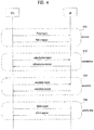
- FIG. 4 is a diagram illustrating a signal flow for a general link setup procedure
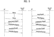
- FIG. 5 is a diagram illustrating signal flows for an active scanning method and a passive scanning method.
- the STA In order to set up a link with a network and transmit/receive data to/from the network, the STA should perform network discovery, authentication, association, and authentication for security.
- the link setup procedure may also be referred to as a session initiation procedure or a session setup procedure.
- discovery, authentication, association, and security setup steps of the link setup procedure may collectively be referred to as an association procedure.
- the STA may perform network discovery.
- the network discovery may include scanning of the STA. That is, the STA should search for an available network so as to access the network.
- the STA should identify a compatible network before joining in a wireless network.
- the process of identifying a network in a specific region is referred to as scanning.
- FIG. 4 illustrates a network discovery operation including active scanning
- the network discovery operation may involve passive scanning.
- a scanning STA transmits a probe request frame and waits for a response to the probe request frame, while switching channels one after another in order to discover an AP around the STA.
- a responder transmits a probe response frame as a response to the probe request frame to the STA that has transmitted the probe request frame.
- the responder may be the last STA that has transmitted a beacon frame in a BSS of a scanned channel. In a BSS, since an AP transmits a beacon frame, the AP is a responder, whereas in an IBSS, since STAs of the IBSS sequentially transmit beacon frames, the responder is not constant.
- an STA may store BSS information included in the received probe response frame, move to the next channel (for example, channel 2), and perform scanning on the next channel in the same manner (i.e., probe request/response transmission/reception on channel 2).
- the scanning operation may also be carried out by passive scanning.
- An STA that performs passive scanning waits for a beacon frame, while switching channels one after another.
- the beacon frame is one of management frames in IEEE 802.11, which is periodically transmitted to indicate the presence of a wireless network, and enable the scanning STA to search for the wireless network and join in the wireless network.
- an AP periodically transmits a beacon frame
- STAs of the IBSS sequentially transmit beacon frames.
- an STA Upon receipt of a beacon frame during scanning, an STA stores BSS information included in the beacon frame, switches to another channel, and records beacon frame information for each channel.
- an STA Upon receipt of a beacon frame during scanning, an STA stores BSS information included in the received beacon frame, switches to the next channel, and performs scanning on the next channel in the same manner.
- a comparison between active scanning and passive scanning reveals that active scanning advantageously has a shorter delay and less power consumption than passive scanning.
- the STA may perform an authentication procedure in step S520.
- the authentication procedure may be referred to as a first authentication procedure to clearly distinguish the authentication procedure from a security setup procedure of step S540.
- the authentication procedure may include transmission of an authentication request frame to an AP by the STA, and transmission of an authentication response frame to the STA by the AP in response to the authentication request frame.
- the authentication frame used for an authentication request/response may be a management frame.
- the authentication frame may include information about an authentication algorithm number, an authentication transaction sequence number, a status code, challenge text, a Robust Security Network (RSN), a Finite Cyclic Group (FCG), and so on.
- the above-mentioned information may be an example of part of information that may be included in the authentication request/response frame, and may be replaced with other information or include additional information.
- the STA may transmit the authentication request frame to the AP.
- the AP may determine whether to authenticate the STA based on information included in the received authentication request frame.
- the AP may provide the result of the authentication to the STA in the authentication response frame.
- the association procedure may involve transmitting an association request frame to the AP by the STA, and transmitting an association response frame to the STA by the AP in response to the association request frame.
- the association request frame may include information about various capabilities, a beacon listen interval, a Service Set Identifier (SSID), supported rates, supported channels, an RSN, a mobility domain, supported operating classes, a Traffic Indication Map (TIM) broadcast request, interworking service capability, and so on.
- SSID Service Set Identifier
- TIM Traffic Indication Map
- the association response frame may include information about various capabilities, a status code, an Association ID (AID), supported rates, an Enhanced Distributed Channel Access (EDCA) parameter set, a Received Channel Power Indicator (RCPI), a Received Signal to Noise Indicator (RSNI), a mobility domain, a timeout interval (association comeback time), an overlapping BSS scan parameter, a TIM broadcast response, a Quality of Service (QoS) map, and so on.
- AID Association ID
- EDCA Enhanced Distributed Channel Access
- RCPI Received Channel Power Indicator
- RSNI Received Signal to Noise Indicator
- mobility domain a timeout interval (association comeback time)
- association comeback time an overlapping BSS scan parameter
- a TIM broadcast response a Quality of Service (QoS) map, and so on.
- QoS Quality of Service
- the above-mentioned information may be an example of part of information that may be included in the association request/response frame, and may be replaced with other information or include additional information.
- a security setup procedure may be carried out in step S540.
- the security setup procedure of step S540 may be referred to as an authentication procedure based on a Robust Security Network Association (RSNA) request/response.
- the authentication procedure of step S520 may be referred to as the first authentication procedure, and the security setup procedure of step S540 may also be simply referred to as an authentication procedure.
- RSNA Robust Security Network Association
- the security setup procedure of step S540 may include, for example, a private key setup procedure through 4-way handshaking based on an Extensible Authentication Protocol over LAN (EAPOL) frame.
- the security setup procedure may also be carried out in a security scheme that has not been defined in the IEEE 802.11 standards.
- FIGS. 6, 7, and 8 are diagrams depicting an operation of an STA in response to reception of a TIM.
- the STA may transition from a sleep state to an awake state in order to receive a beacon frame including a TIM from an AP, and may determine the presence of buffered traffic to be transmitted to the STA by interpreting a received TIM element.
- PS-Poll Power Save-Poll
- the STA may transmit the PS-Poll frame to the AP to request transmission of a data frame.
- the AP may transmit a data frame to the STA.
- the STA may receive the data frame and transmit an ACKnowledgement (ACK) frame for the received data frame to the AP. Then, the STA may return to the sleep state.
- ACK ACKnowledgement
- the AP may transmit the data frame a predetermined time (e.g., a Short Inter-Frame Space (SIFS)) after receiving the PS-Poll frame from the STA, that is, the AP may operate in an immediate response scheme.
- a predetermined time e.g., a Short Inter-Frame Space (SIFS)
- SIFS Short Inter-Frame Space
- the AP may operate in a deferred response scheme, which will be described with reference to FIG. 7 .
- the STA transitions from the sleep state to the awake state, receives a TIM from the AP, and transmits a PS-Poll frame to the AP after contention in the same manner as in the example of FIG. 6 .
- the AP may transmit an ACK frame to the STA, instead of the data frame.
- the AP may transmit the data frame to the STA after contention.
- the STA may transmit an ACK frame indicating successful reception of the data frame to the AP, and then transition to the sleep state.
- FIG. 8 is a view illustrating exemplary transmission of a Delivery TIM (DTIM) from an AP.
- STAs may transition from the sleep state to the awake state to receive a beacon frame including a DTIM element from the AP.
- the STAs may determine from the received DTIM that a multicast/broadcast frame will be transmitted.
- the AP may transmit data (i.e., the multicast/broadcast frame) immediately without transmitting/receiving a PS-Poll frame.
- the STAs may receive data, maintaining the awake state after receiving the beacon frame including the DTIM, and return to the sleep state, after completion of the data reception.
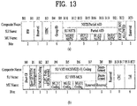
- FIGS. 9 to 13 are views illustrating exemplary frame structures in an IEEE 802.11 system.
- An STA may receive a Physical Layer Convergence Protocol (PLCP) Packet Data Unit (PPDU).
- PLCP Physical Layer Convergence Protocol
- PPDU Packet Data Unit
- a PPDU frame format may include Short Training Field (STF), Long Training Field (LTF), SIGNAL (SIG), and Data.
- STF Short Training Field
- LTF Long Training Field
- SIGNAL SIGNAL
- Data Data
- a PPDU format may be configured according to the type of the PPDU frame format.
- a non-High Throughput (non-HT) PPDU frame format may include only Legacy-STF (L-STF), Legacy-LTF (L-LTF), SIG, and Data.
- L-STF Legacy-STF
- L-LTF Legacy-LTF
- SIG SIG
- Data Data
- the type of a PPDU frame format be one of HT-mixed format PPDU and HT-greenfield format PPDU.
- An additional STF, LTF, and SIG field (or an STF, an LTF, and a SIG field of a different type) may be included between the SIG field and the Data field in the above-described PPDU formats.
- VHT Very High Throughput
- An additional STF, LTF, and SIG field may also be included between the SIG field and the Data field in the VHT PPDU format. More specifically, at least one of VHT-SIG-A, VHT-STF, VHT-LTF, and VHT-SIG-B may be included between the L-SIG field and the Data field in the VHT PPDU format.
- STF may be a signal used for Automatic Gain Control (AGC), diversity selection, fine time synchronization, and so on.
- LTF may be a signal used for channel estimation, frequency error estimation, and so on.
- STF and LTF may be collectively called a PLCP preamble, and the PLCP preamble may be a signal used for synchronization and channel estimation at an OFDM physical layer.
- the SIG field may include RATE and LENGTH.
- the RATE field may include information about modulation and a coding rate of data
- the LENGTH field may include information about the length of the data.
- the SIG field may include a parity bit, SIG TAIL bits, and so on.
- the Data field may include a SERVICE field, a PLCP Service Data Unit (PSDU), and PPDU TAIL bits. When needed, the Data field may further include padding bits.
- PSDU PLCP Service Data Unit
- PPDU TAIL bits When needed, the Data field may further include padding bits.
- a part of the bits of the SERVICE field may be used for synchronization of a descrambler in a receiver, and another part of the bits of the SERVICE field may be reserved.
- the PSDU corresponds to a MAC Protocol Data Unit (MAC PDU) defined in the MAC layer, and may include data generated/used in a higher layer.
- the PPDU TAIL bits may be used to return an encoder to a zero state.
- the padding bits may be used to match the length of the Data field on a predetermined unit basis.
- the VHT PPDU format may include an additional STF, LTF, and SIG field (or an STF, LTF, and SIG field of a different type), as described before.
- L-STF, L-LTF, and L-SIG of a VHT PPDU may be a non-VHT part
- VHT-SIG-A, VHT-STF, VHT-LTF, and VHT-SIG-B of the VHT PPDU may be a VHT part.
- areas for non-VHT fields and VHT fields may be defined separately in the VHT PPDU.
- VHT-SIG-A may include information used to interpret the VHT PPDU.
- VHT-SIG-A may include VHT-SIG-A1 ((a) of FIG. 13 ) and VHT-SIG-2 ((b) of FIG. 13 ).
- Each of VHT-SIG-A1 and VHT-SIG-A2 may include 24 data bits, and VHT-SIG-A1 may be transmitted before VHT-SIG-A2.
- VHT-SIG-A1 may include BandWidth (BW), Space Time Block Coding (STBC), Group ID, Number of Space-Time Streams/Partial Association ID (NSTS/Partial AID), TXOP_PS_NOT_ALLOWED, and Reserved.
- VHT-SIG-2 may include Short Guard Interval (GI), Short GI NSYM Disambiguation, Single User/Multi-User[0] Coding (SU/MU[0] Coding), Low Density Parity Check (LDPC) Extra OFDM Symbol, SU VHT-MCS/MU[1-3] Coding, Beamformed, Cyclic Redundancy Check (CRC), Tail, and Reserved. Information about a VHT PPDU may be acquired from these fields.
- GI Short Guard Interval
- SU/MU[0] Coding Single User/Multi-User[0] Coding
- LDPC Low Density Parity Check
- Extra OFDM Symbol SU VHT-MCS/MU[1-3] Coding
- Beamformed Cyclic Redundancy Check (CRC)
- CRC Cyclic Redundancy Check
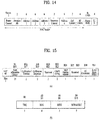
- FIGS. 14, 15 , and 16 are views illustrating a MAC frame format.
- An STA may receive a PPDU in one of the above-described PPDU formats.
- a PSDU in a data part of the PPDU frame format may include a MAC PDU.
- the MAC PDU may be defined in various MAC frame formats, and a basic MAC frame may include a MAC header, Frame Body, and Frame Check Sequence (FCS).
- FCS Frame Check Sequence
- the MAC header may include Frame Control, Duration/ID, Address, Sequence Control, QoS Control, and HT Control.
- the Frame Control field may include control information required for frame transmission/reception.
- the Duration/ID field may be set to a time required to transmit a frame.
- the Address fields may include identification information about a transmitter and a receiver, which will be described later.
- Sequence Control, QoS Control, and HT Control fields refer to the IEEE 802.11 standard specifications.
- the HT Control field may be configured in two types, HT variant and VHT variant, and include different information according to the types.
- a VHT subfield of the HT Control field may indicate whether the HT Control field is of the HT-variant type or the VHT-variant type. For example, if the VHT subfield is set to '0', the HT Control field may be of the HT-variant type, and if the VHT subfield is set to '1', the HT Control field may be of the VHT-variant type.
- the HT Control field may include Link Adaptation Control, Calibration Position, Calibration Sequence, CSI/Steering, HT NDP Announcement, AC constraint, RDG/More PPDU, and Reserved.
- the Link Adaptation Control field may include TRQ, MAI, MFSI, and MFB/ASELC. For more details, refer to the IEEE 802.11 standard specifications.
- the HT Control field may include MRQ, MSI, MFSI/GID-LM, MFB GID-H, Coding Type, FB Tx Type, Unsolicited MFB, AC constraint, RDG/More PPDU, and Reserved.
- the MFB field may include VHT N_STS, MCS, BW, and SNR.
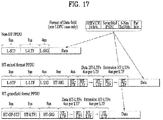
- FIG. 17 is a diagram illustrating a Short MAC frame format.
- a MAC frame may be configured as a Short MAC frame by reducing unnecessary information when needed, to prevent waste of radio resources.
- the MAC header of a Short MAC frame may always include a Frame Control field, an A1 field, and an A2 field.
- the MAC header may selectively include a Sequence Control field, an A3 field, and an A4 field. Since information unnecessary for a MAC frame is not included in a Short MAC frame in this manner, radio resources may be conserved.
- the Frame Control field of the MAC header may include Protocol Version, Type, PTID/Subtype, From DS, More Fragment, Power Management, More Data, Protected Frame, End of Service Period, Relayed Frame, and Ack Policy.
- Protocol Version For a description of each subfield of the Frame Control field, refer to the IEEE 802.11 standard specifications.
- the Type field is 3 bits in the Frame Control field of the MAC header, with value 0 to value 3 providing address information and value 4 to value 7 being reserved. New address information may be provided using the reserved values in the present invention, which will be described later.
- the From DS field may be 1 bit.
- Each of the More Fragment, Power Management, More Data, Protected Frame, End of Service Period, Relayed Frame, and Ack Policy fields may be 1 bit.
- the Ack Policy field may provide ACKnowledgement/Negative ACKnowledgement (ACK/NACK) information in 1 bit.
- an AP VHT STA may support a non-AP VHT STA operating in a Transmit Opportunity (TXOP) power save mode in a BSS.
- TXOP Transmit Opportunity
- the AP VHT STA may switch the non-AP VHT STA to the doze state during a TXOP.
- the AP VHT STA may command the non-AP VHT STA to switch to the doze state by transmitting a VHT PPDU with a TXVECTOR parameter, TXOP_PS_NOT_ALLOWED set to 0. Parameters in TXVECTOR transmitted along with the VHT PPDU by the AP VHT STA may be changed from 1 to 0 and maintained during the TXOP. Therefore, power may be saved during the remaining TXOP.
- TXOP_PS_NOT_ALLOWED is set to 1 and thus power saving is not performed, the parameters in TXVECTOR may be kept unchanged.
- the non-AP VHT STA may switch to the doze state in the TXOP power save mode during a TXOP, if the following conditions are satisfied.
- the AP VHT STA may include a Duration/ID value set to the remaining TXOP interval and a NAV-SET Sequence (e.g., Ready To Send/Clear To Send (RTS/CTS)).
- RTS/CTS Ready To Send/Clear To Send
- the AP VHT STA may not transmit a frame to a non-AP VHT STA switching to the doze state based on the above-described conditions during the remaining TXOP.
- the AP VHT STA may not transmit a VHT SU PPDU.
- the AP VHT STA may not transmit a frame to a VHT STA that has switched to the doze state before timeout of a NAV set at the start of a TXOP.
- the AP VHT STA may retransmit the frame at least once in the same TXOP. For example, if the AP VHT STA fails to receive an ACK for a retransmission in the last frame of the same TXOP, the AP VHT STA may retransmit the frame after waiting until the next TXOP.
- MSDU MAC Service Data Unit
- A-MSDU Aggregated-MSDU
- MMPDU MAC Management Protocol Data Unit
- the AP VHT STA may receive a Block Ack frame from a VHT STA operating in the TXOP power save mode.
- the Block Ack frame may be a response to an A-MPDU including an MPDU with More Data set to 0.
- the AP VHT STA is in the doze state and may not receive a response to the sub-sequence of a retransmitted MPDU during the same TXOP.
- a VHT STA that has operated in the TXOP power save mode and switched to the doze state may activate a NAV timer while it stays in the doze state. For example, upon expiration of the timer, the VHT STA may transition to the awake state.
- the STA may contend for medium access, upon expiration of the NAV timer.
- a UE performs random access to transmit a UL signal, with no resources allocated by an eNB.
- a WLAN system does not need random access much, compared to the cellular system, because a frame is transmitted in a contention-based manner between an AP and an STA or between STAs.
- FIG. 18 is a view illustrating a random access method in a WLAN system according to an embodiment of the present invention.
- an afore-mentioned beacon frame and a trigger frame may be used for efficient random access in a WLAN system.
- random access resources are allocated to an STA by a Trigger Frame for Random Access (TF-R), and information about transmission times of one or more TF-Rs is transmitted by a beacon frame.
- TF-R Trigger Frame for Random Access
- an AP may include TF-R transmission start information (e.g., TF-R Start Timer 1 and TF-R Start Timer 2) in a beacon frame. If random access resources are allocated to STA 1 and STA 2 by a TF-R transmitted at a time point indicated by TF-R Start Time 1 in FIG. 18 , STA 1 and STA 2 preferably operate in the doze state until the time point indicated by TF-R Start Time 1, thereby minimizing power consumption.
- TF-R transmission start information e.g., TF-R Start Timer 1 and TF-R Start Timer 2
- each of a plurality of TF-Rs illustrated in FIG. 18 includes a 1-bit cascade indicator indicating whether the TF-Rs are cascaded. It may occur that it is difficult to allocate random access resources with one TF-R, and an embodiment of the present invention proposes that random access resource allocation through a plurality of TF-Rs is supported by means of the cascade indicator.
- the STAs may select random resources from the random access resources allocated by the TF-R information, and transmit a random access request message in a UL data frame using the selected resources.
- a back-off procedure may be defined to reduce a collision probability in the case where STA 1 or STA 2 randomly selects random access resources and transmits a UL frame.
- the back-off procedure may be defined as OFDMA Back-Off (OBO) or simply Back-Off (BO).
- FIG. 19 is a diagram illustrating a method for performing random access based on OBO according to an embodiment of the present invention.
- each STA may select a value randomly within a specific window and set the selected value as an OBO value.
- the window used for the OBO operation is defined as an OFDMA Contention Window (CWO).
- CWO OFDMA Contention Window
- STA 1 sets 3 as a BO value
- STA 2 sets 5 as a BO value.
- These BO (OBO) values are selected randomly from the range of a predetermined CWO.
- An AP may transmit information needed for CWO value setting of each STA in a beacon frame or its equivalent frame.
- STAs decrement their OBO (BO) values, each time by a random access resource allocation unit, and if the OBO (BO) value of an STA reaches 0, the STA transmits a UL frame in resources selected randomly from among random access resources allocated to the STA. While each TF-R transmission unit is assumed to be one random access resource unit in the example of FIG. 19 , there is no need for limiting the random access resource unit to a TF-R transmission unit.
- STA 1 and STA 2 decrement their OBO values by 1 every TF-R reception unit (every random access resource allocation unit) in the example of FIG. 19 .
- STA 1 may transmit UL data after three random access resource units because it has started back-off with a BO of 3
- STA 2 may transmit UL data after five random access resource units because it has started back-off with a BO of 5.
- an STA receiving a TF-R with a cascade indicator set to 1 does not operate in the doze state until receiving a TF-R with a cascade indicator set to 0.
- an STA receiving a TF-R with a cascade indicator set to 0 may enter the doze state until another TF-R reception time.
- STAs perform back-off countdown, while continuously receiving TF-Rs according to their selected OBO values.
- efficiency may be decreased in terms of power consumption of the STA.
- an AP indicates the number of random access resource units in a corresponding beacon interval to each STA by a beacon frame, and if its OBO value is larger than the number of random access resource units in the beacon interval, the STA operates in the doze state during the beacon interval.
- the STA may decrement its OBO value by the number of random access resource units in the beacon interval and perform a back-off procedure in another beacon interval.
- FIG. 20 is a view illustrating a method for indicating the number of random access resource units in a corresponding beacon interval by a beacon frame according to a preferred embodiment of the present invention.
- FIG. 20 a case in which with a selected BO of 4, STA 2 operates in the doze state during a beacon interval in the above-described method is compared with a case in which with a selected BO of 4, STA 2 does not operate in the doze state during a beacon interval.
- STA 2 In a general back-off method, with a BO of 4, STA 2 operates in the doze state until a time point indicated by TF-R Start Time 1 and then receives TF-Rs. STA 2 decrements the BO value by 1 every random access resource unit, and finally transmits a UL frame after four random access resource units.
- the first of one or more TF-Rs provides information about the number of random access resource units in a corresponding beacon interval, instead of a beacon frame.
- FIG. 21 is a view illustrating a method for providing information about the number of random access resource units by a first TF-R according to a preferred example not falling within the scope of the present invention.
- STA 2 may receive each TF-R and decrement its BO value by 1 each time.
- STA 2 which uses information about the number of random access units, included in a first TF-R according to an example not falling within the scope of the present invention, operates in the doze state from a corresponding time to the next beacon reception time, and control its OB value accordingly.
- a random access resource allocation unit corresponds to one TF-R interval in the foregoing examples not falling within the scope of the present invention
- a plurality of random access resource units may be allocated by one TF-R. If a plurality of random access resource units are allocated by one TF-R, each STA may decrement its OBO (OB) value by the number of random access resource units allocated to the STA, which will be described later with reference to FIG. 21 .
- OB OBO
- an AP may restrict STAs which may transmit UL frames in resources for UL OFDMA random access in order to reduce a collision probability during UL OFDMA random access of STAs.
- the AP may allow an STA with an odd-numbered AID to transmit a signal in resources for UL OFDMA random access allocated by a specific trigger frame, and an STA with an even-numbered AID to transmit a signal in resources for UL OFDMA random access allocated by another trigger frame.
- the AP may allow only STAs having Received Signal Strength Indicator (RSSI) values equal to or larger than a predetermined value to transmit a signal in random resources for UL OFDMA random access.
- RSSI Received Signal Strength Indicator
- the AP may transmit information corresponding to these conditions in a trigger frame or a beacon frame.
- the AP may transmit information about the number of back-off units for random access (e.g., TF-Rs, slots, or random access resource units) in a current beacon interval or cascaded TF-Rs by a beacon frame or a TF-R (the first of the cascaded TF-Rs) in order to save power of STAs performing UL OFDMA random access.
- the AP may need to indicate, by the beacon frame or the first of the cascaded TF-Rs, whether information for restricting access of the STAs performing UL OFDMA random access in the cascaded TF-Rs is transmitted.
- an STA receiving the beacon frame may compare its back-off count with the number of BO units supposed to be transmitted during a current Target Beacon Transmission Time (TBTT) (the number of BO units may be indicated in the beacon frame by the AP). If the back-off count is larger than the number of BO units, the STA may maintain the doze mode until the next TBTT (herein, the STA decrements its back-off count by the number of BO units to be transmitted during the current beacon interval). Otherwise, the STA performs random access, maintaining the awake mode.
- TBTT Target Beacon Transmission Time
- an STA may compare its back-off count with the number of BO units to be transmitted during the current cascaded TF-Rs. If the back-off count is larger than the number of BO units to be transmitted during the current cascaded TF-Rs, the STA indicates a target transmission time by a beacon and then maintain the doze mode until the next trigger frame (or the first of the next cascaded TF-Rs) (herein, the STA decrements its back-off count by the number of BO units to be transmitted during the current beacon interval). Otherwise, the STA performs random access, maintaining the awake mode.
- the AP allocates resources for UL OFDMA random access by a TF or a TF-R
- STAs receiving the TF or TF-R may determine the number of back-off units for random access (e.g., TF-Rs or random access resource units) in the multiple slots allocated by the TF or the TF-R, and save power during the multiple slots by comparing the number of back-off units for random access with their back-off counts.
- FIG. 22 is a view illustrating a method for performing a back-off procedure according to resource units allocated on an STA basis according to an embodiment of the present invention.
- FIG. 22 is based on the assumption that random access is performed using multiple slots indicated by a TF-R. For example, if BO values is 2 and 4, respectively for STA 1 and STA 2, STA 1 and STA 2 may switch from the doze state to the awake state and receive a TF-R at a TF-R target transmission time indicated by a beacon frame.
- STA 1 and STA 2 may determine the number of back-off units allocated by the TF-R based on information transmitted in the TF-R (e.g., the number of multiple slots or the number of Random Access-Resource Units (RA-RUs): this information may be indicated explicitly (by a common field or the like) or may be known from information about resources allocated for random access by the AP), and determine whether they may occupy a channel by random access, based on the determined number of back-off units. That is, an STA may determine whether a BO value is decremented to 0 and thus a UL frame may be transmitted.
- RA-RUs Random Access-Resource Units
- STA 1 and STA 2 are capable of determining that the number of back-off units for resources allocated by a TF-R by receiving the TF-R, they may compare their back-off counts with the number of resource back-off units allocated by the TF-R. If its back-off count is larger than the number of resource back-off units allocated by the TF-R, an STA may transition to the doze state and maintain the doze state until the target transmission time of the next TF-R. That is, the STA may switch to the awake mode at the next TF-R target transmission time and receive the next TF-R. Preferably, the STA decrements its back-off count by the number of back-off units (e.g., the number of slots or random access resource units) known from the TF-R received in the previous operation.
- the number of back-off units e.g., the number of slots or random access resource units
- the STA may perform random access, maintaining the awake mode.
- the STA may maintain the awake mode, without saving power.
- the AP may indicate the number of back-off units according to each restriction condition. For example, if UL OFDMA random access of STAs is restricted according to odd and even numbers, the AP may indicate the number of back-off units transmitted in a current beacon interval or TF-R interval, for each case. Or the AP may indicate the number of back-off units for each group ID. In this case, the STA may determine whether to perform a power save procedure according to a predefined back-off rule.
- the STA may perform the foregoing operation by comparing the number of the back-off units with its back-off count. Or if the STA follows the back-off rule unconditionally, the STA may compare the sum of the indicated numbers of back-off units for the respective conditions with its back-off count, and perform the afore-mentioned power save procedure irrespective of odd/even numbers.
- FIGS. 23 , 24 , and 25 are views illustrating various methods for restricting random access of STAs by an AP according to an example not falling within the scope of the present invention.
- an STA may decrement a back-off count by 1 every back-off unit for random access (e.g., every TF-R, slot, or random access resource unit), only if an access restriction condition indicated by the trigger frame is satisfied.
- the STA selects resources randomly from resources allocated by the trigger frame and transmit a
- FIG. 23 illustrates a case in which a back-off unit is a TF-R.
- STA 1 has an even-numbered AID
- STA 2 has an odd-numbered AID, by way of example.
- Each STA decrements a BO by 1 every TF-R corresponding to a back-off unit allocated to the STA, instead of every TF-R corresponding to a back-off unit.
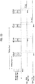
- FIG. 24 is a view illustrating a case in which a back-off unit is a slot.
- five slots are allocated by one TF-R.
- An odd-numbered slot is allocated to an STA having an odd-numbered AID
- an even-numbered slot is allocated to an STA having an even-numbered AID.
- each of STA 1 and STA 2 may decrement a BO value by 1 every even-numbered or odd-numbered slot.
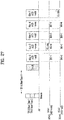
- FIG. 25 is a view illustrating a case in which a back-off unit is a random access resource unit in the frequency domain.
- a plurality of random access resources in the frequency domain are allocated by one TF-R.
- a specific random access resource may be allocated to an STA having an even-numbered AID, and another specific random access resource may be allocated to an STA having an odd-numbered AID.
- each STA may decrement its BO value by the number of random access resource units allocated to the STA.
- an STA receiving the information may compare its back-off count with the number of back-off units for a condition If the back-off count is larger than the number of back-off units, the STA may enter the doze state, and otherwise, the STA may transmit a UL frame, maintaining the awake state. When entering the doze state, the STA may decrement its back-off count by the number of back-off units for the condition, indicated by the AP.
- each STA may decrement a BO value even in a back-off unit in which resources are not allocated to the STA.
- FIGS. 26 , 27 , and 28 are views illustrating methods for decrementing a BO value every back-off unit according to another example not falling within the scope of the present invention.
- FIG. 26 illustrates a case in which a back-off unit is a TF-R
- FIG. 27 illustrates a case in which a back-off unit is a slot
- FIG. 28 illustrates a case in which a back-off unit is a random access resource unit.
- an STA receiving the information may compare its back-off count with the number of back-off units for a condition. If the back-off count is larger than the number of back-off units, the STA may enter the doze state, and otherwise, the STA may transmit a UL frame, maintaining the awake state. When entering the doze state, the STA may decrement its back-off count by the number of back-off units for the condition, indicated by the AP.
- the STA may also decrement the back-off count by 1 every back-off unit (e.g., every TF-R, slot, or random access resource unit) irrespective of whether the UL OFDMA random access restriction condition indicated by the AP is satisfied. In this case, if the condition is not satisfied although the back-off count is 0, the STA preferably maintains the back-off count to be 0 without transmitting a UL frame. Then, the STA may select a random value again from a range of [0 CWmin] after transmitting the UL frame.
- every back-off unit e.g., every TF-R, slot, or random access resource unit
- the foregoing embodiments propose a method for saving more power for STAs by indicating the total number of Resource Units (RUs), for UL OFDMA random access.
- an AP should have prior knowledge of the number of RUs or calculate the number of RUs to indicate the total number of RUs by a beacon frame or a TF-R. If the AP is not capable of calculating or preliminarily determining the number of RUs, the AP should enable STAs to operate based on the existing cascade indication.
- a total RU number information bit is set to 0. Since the total number of RUs is not indicated, this may be considered to indicate explicitly that an existing cascade indication is used.
- 2-bit total RU number information is provided. If this information is set to 0, this may indicate that the total number of RUs will be indicated. If this information is set to 255 (or a maximum value of the bits), this may indicate that the total number of RUs will not be indicated.
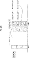
- FIG. 29 is a view illustrating an exemplary High Efficiency (HE) PPDU format according to an example not falling within the scope of the present invention.
- HE High Efficiency
- IEEE 802.11ax a legacy 1x symbol structure (3.2 ⁇ s) is adopted for a part of the frame up to HE-SIG-A, and a frame structure as illustrated in FIG. 29 may be used for the remaining part of the frame from HE-SIG-B, as illustrated in FIG. 29 .
- a legacy 1x symbol structure (3.2 ⁇ s) is adopted for a part of the frame up to HE-SIG-A, and a frame structure as illustrated in FIG. 29 may be used for the remaining part of the frame from HE-SIG-B, as illustrated in FIG. 29 .
- An L-part may be configured as in a legacy Wireless Fidelity (WiFi) system, and thus may include L-STF, L-LTF, and L-SIG.
- L-SIG preferably provides packet length information.
- a HE-part is a new part configured for the 11ax standard (High Efficiency).
- HE-SIG (HE-SIGA and HE-SIGB) may be interposed between the L-part and HE-STF, providing common control information and user-specific information.
- HE-SIGA may provide common control information
- HE-SIGB may provide user-specific information.
- information of HE-SIG has not been defined yet in IEEE 802.11ax
- HE-SIGA and HE-SIGB may include the following information.
- GI Guard Interval
- MU indication Indicating whether a PPDU is an SU-MIMO PPDU or an MU-MIMO PPDU
- Table 2 Field Description Partial AID MCS Indicating the MCS of Data for each STA Stream information Indicating the number of spatial streams for each STA, encoding Indicating whether BCC or LDPC beam formed Indicating whether beam forming or not Guard Interval (GI) indication Indicating the CP length of Data for each STA Allocation information Indicating a resource block (subchannel index or subband index) allocated to each STA in a bandwidth in which a PPDU is transmitted STBC Space Time Block Coding length Indicating the length of HE PPDU is transmitted in a bandwidth
- FIG. 30 is a block diagram illustrating an exemplary structure of an AP (or BS) and an STA (or UE) according to an embodiment of the present invention.
- An AP 100 may include a processor 110, a memory 120, and a transceiver 130.
- An STA 150 may include a processor 160, a memory 170, and a transceiver 180.
- the transceivers 130 and 180 may transmit and receive wireless signals, for example, implement the Physical (PHY) layer in an IEEE 802 system.
- the processors 110 and 160 may be connected to the transceivers 130 and 180, and implement the PHY layer and/or the MAC layer in the IEEE 802 system.
- the processors 110 and 160 may be configured to perform one or a combination of two or more of the foregoing various embodiments of the present invention.
- modules that perform AP and STA operations according to the foregoing various embodiments of the present invention may be stored in the memories 120 and 170 and executed by the processors 110 and 160.
- the memories 120 and 170 may be included inside the processors 110 and 160, or may be installed outside the processors 110 and 160 and connected to the processors 110 and 160 by known means.
- the above descriptions of the AP 100 and the STA 150 are applicable to a BS and a UE, respectively in other wireless communication systems (e.g., an LTE/LTE-A system).
- FIG. 31 is a view illustrating an exemplary structure of a processor in an AP or STA according to an example not falling within the scope of the present invention.
- the processor of the AP or STA may have a multi-layered structure.
- FIG. 31 focuses on a MAC sublayer 3810 of a Data Link Layer (DLL) and a PHY layer 3820 among a plurality of layers.
- the PHY layer 3820 may include a PLCP entity 3821, and a Physical Medium Dependent (PMD) entity 3822.
- PMD Physical Medium Dependent
- Each of the MAC sublayer 3810 and the PHY layer 3820 includes a management entity conceptually called MAC sublayer Management Entity (MLME) 3811.
- MLME MAC sublayer Management Entity
- a Station Management Entity (SME) 3830 is present in each STA.
- the SME 3830 is a layer-independent entity that may be viewed as residing in a separate management plane or as residing off to the side.
- the exact functions of the SME 3830 are not specified herein, but in general, this entity may be viewed as being responsible for such functions as gathering of information about layer-dependent statuses from various Layer Management Entities (LMEs) and similar setting of the values of layer-specific parameters.
- LMEs Layer Management Entities
- the SME 3830 may typically perform such functions on behalf of general system management entities and may implement standard management protocols.
- FIG. 31 illustrates a couple of examples of exchanging GET/SET primitives.
- An XX-GET.request primitive is used to request the value of a given Management Information Base (MIB) attribute.
- MIB Management Information Base
- An XX-GET.confirm primitive returns an appropriate MIB attribute value if Status is set to "success" and otherwise, returns an error indication in a Status field.
- An XX-SET.request primitive is used to request that an indicated MIB attribute be set to a given value. If this MIB attribute implies a specific action, then this requests that the action be performed.
- An XX-SET.confirm primitive confirms that an indicated MIB attribute was set to a requested value, if Status is set to "success,” and otherwise, it returns an error condition in the Status field. If this MIB attribute implies a specific action, then this confirms that the action was performed.
- the MLME 381 and the SME 3830 may exchange various MLME_GET/SET primitives via an MLME Service Access Point (MLME_SAP) 3850.
- various PLCM_GET/SET primitives may be exchanged between the PLME 3821 and the SME 3830 via a PLME_SAP 3860 and between the MLME 3811 and the PLME 3870 via an MLME-PLME_SAP 3870.
- the embodiments of the present invention may be implemented by various means, for example, in hardware, firmware, software, or a combination thereof.
- the method according to the embodiments of the present invention may be implemented by one or more Application Specific Integrated Circuits (ASICs), Digital Signal Processors (DSPs), Digital Signal Processing Devices (DSPDs), Programmable Logic Devices (PLDs), Field Programmable Gate Arrays (FPGAs), processors, controllers, microcontrollers, microprocessors, or the like.
- ASICs Application Specific Integrated Circuits
- DSPs Digital Signal Processors
- DSPDs Digital Signal Processing Devices
- PLDs Programmable Logic Devices
- FPGAs Field Programmable Gate Arrays
- processors controllers, microcontrollers, microprocessors, or the like.
- the method according to the embodiments of the present invention may be implemented in the form of modules, procedures, functions, or the like that perform the above-described functions or operations.
- Software code may be stored in a memory unit and executed by a processor.
- the memory unit may be located at the interior or exterior of the processor and may transmit and receive data to and from the processor via various known means.
- the embodiments of the present invention are applicable to various wireless communication systems including an IEEE 802.11 system.
Description
- The present invention relates to a Wireless Local Area Network (WLAN) system, and more particularly, to a method and apparatus for efficiently performing random access to an Access Point (AP) by a Station (STA) in a WLAN system.
- While a proposed random access method as set forth below is applicable to various types of wireless communication, the random access method will be described below in the context of a WLAN system as an example of a system to which the present invention is applicable.
- Standards for a WLAN technology have been developed as Institute of Electrical and Electronics Engineers (IEEE) 802.11 standards. IEEE 802.11a and 802.11b use an unlicensed band at 2.4GHz or 5GHz. IEEE 802.11b provides a transmission rate of 11Mbps, and IEEE 802.11a provides a transmission rate of 54Mbps. IEEE 802.11g provides a transmission rate of 54Mbps by applying Orthogonal Frequency Division Multiplexing (OFDM) at 2.4GHz. IEEE 802.11n provides a transmission rate of 300Mbps for four spatial streams by applying Multiple Input Multiple Output-OFDM (MIMO-OFDM). IEEE 802.11n supports a channel bandwidth of up to 40MHz and, in this case, provides a transmission rate of 600Mbps.
- The above-described WLAN standards have evolved into IEEE 802.11ac that supports a transmission rate of up to 1 Gbit/s by using a bandwidth of up to 160MHz and supporting eight spatial streams, and IEEE 802.11ax standardization is under discussion.
- Non-patent disclosure Chittabrata Ghosh (Intel): "Random Access with Trigger Frames using OFDMA", IEEE draft, vol. 802.11ax, 11 May 2015, XP068094472, outlines a random access mechanism with Trigger frames for UL MU transmissions. In the document, the Trigger frames are described to support allocation of resource units for random access and STAs are disclosed to randomly select among the resource units for their UL MU PPDU transmissions.
- An object of the present invention is to provide an efficient random access method and a method for efficiently transmitting and receiving data using the random access method, in a Wireless Local Area Network (WLAN) system.
- The present invention is not limited to the above object, and other objects of the present invention will be apparent from the embodiments of the present invention.
- Preferred embodiments of the present disclosure are provided as defined in the appended claims. In one aspect of the present disclosure, a method for performing uplink Orthogonal Frequency Division Multiple Access (UL OFDMA) based random access to an Access Point (AP) by a Station (STA) in a Wireless Local Area Network (WLAN) system includes setting a random value within an OFDMA Contention Window (CWO) as an OFDMA Back-Off (OBO) value, receiving a beacon frame from the AP, the beacon frame including transmission start time information of one or more Trigger Frames for Random Access (TF-Rs), decrementing the OBO value based on reception of the one or more TF-Rs, and if the OBO value reaches 0, transmitting a random access request frame in a resource selected randomly from among resources allocated to the STA.
- After receiving the beacon frame, the STA may operate in a doze state until a transmission start time indicated by the transmission start time information of the one or more TF-Rs.
- When the STA receives a specific TF-R among the one or more TF-Rs, the STA may decrement the OBO value by a value corresponding to the number of random access resource units allocated to the STA by the specific TF-R.
- The specific TF-R may allocate a plurality of random access resource units to the STA.
- The STA may additionally check information about the number of random access resource units within a beacon interval through the beacon frame, and if the number of random access resource units in the beacon interval is smaller than the OBO value of the STA, the STA may operate in the doze state during the beacon interval. Herein, the STA may reset the OBO value to a value obtained by decrementing the OBO value by a value corresponding to the number of random access resource units in the beacon interval. If the information about the number of random access resource units in the beacon interval of the beacon frame has a specific value, the STA may operate, assuming that the AP is not capable of determining the number of random access resource units in the beacon interval.
- On the other hand, the STA may additionally check information about the number of random access resource units in the beacon interval through an initial TF-R of the one or more TF-Rs, and if the number of random access resource units in the beacon interval is smaller than the OBO value of the STA, the STA may operate in the doze state during the beacon interval. Herein, the STA may reset the OBO value to a value obtained by decrementing the OBO value by a value corresponding to the number of random access resource units in the beacon interval. If the information about the number of random access resource units in the beacon interval, included in the first of the one or more TF-Rs has a specific value, the STA may operate, assuming that the AP is not capable of determining the number of random access resource units in the beacon interval. Each of the one or more TF-Rs may include a 1-bit cascade indicator indicating whether the TF-R is cascaded.
- If the STA receives a TF-R having a cascade indicator set to 1, the STA may operate in an awake state until receiving a TF-R having a cascade indicator set to 0.
- Further, the STA may additionally check information about the number of random access resource units in the beacon interval through an initial TF-R of a plurality of cascaded TF-Rs, and if the number of random access resource units in the beacon interval is smaller than the OBO value of the STA, the STA may operate in the doze state during the beacon interval.
- In another aspect of the present disclosure, an STA for performing random access to an AP based on uplink OFDMA in a WLAN system includes a transceiver configured to transmit and receive wireless signals to and from the AP, and a processor connected to the transceiver and configured to set a random value within a CWO as an OBO value, to receive a beacon frame from the AP, the beacon frame including transmission start time information of one or more TF-Rs, to decrement the OBO value based on reception of the one or more TF-Rs, and if the OBO value reaches 0, to transmit a random access request frame in a resource selected randomly from among resources allocated to the STA.
- Upon receipt of a specific TF-R among the one or more TF-Rs, the processor may be configured to decrement the OBO value by a value corresponding to the number of random access resource units allocated to the STA by the specific TF-R.
- The specific TF-R may allocate a plurality of random access resource units to the STA.
- Each of the one or more TF-Rs may include a 1-bit cascade indicator indicating whether the TF-R is cascaded.
- According to an embodiment of the present invention, a Station (STA) can perform random access with a decreased collision probability, while minimizing its power consumption in a Wireless Local Area Network (WLAN) system.
- Further, random access resources can be allocated flexibly, using a beacon frame and a Trigger Frame for Random access (TF-R).
- The effects of the present invention are not limited to the above-described effects and other effects which are not described herein will be understood by those skilled in the art from the following description of the embodiments of the present invention.
-
-
FIG. 1 is a view illustrating an exemplary configuration of a Wireless Local Area Network (WLAN) system. -
FIG. 2 is a view illustrating another exemplary configuration of a WLAN system. -
FIG. 3 is a view illustrating an exemplary structure of a WLAN system. -
FIG. 4 is a diagram illustrating a signal flow for a general link setup procedure. -
FIG. 5 is a diagram illustrating signal flows for an active scanning method and a passive scanning method. -
FIGS. 6, 7, and 8 are views illustrating operations of a Station (STA) in response to reception of a Traffic Indication Map (TIM). -
FIGS. 9 to 13 are views illustrating exemplary frame structures in an Institute of Electrical and Electronics Engineers (IEEE) 802.11 system. -
FIGS. 14, 15 , and16 are views illustrating a Medium Access Control (MAC) frame format. -
FIG. 17 is a view illustrating a Short MAC frame format. -
FIG. 18 is a view illustrating a random access method in a WLAN system according to an embodiment of the present invention. -
FIG. 19 is a view illustrating a method for performing random access based on Orthogonal Frequency Division Multiple Access (OFDMA) Back-Off (OBO) according to an embodiment of the present invention. -
FIG. 20 is a view illustrating a method for indicating the number of random access resource units in a beacon interval by a beacon frame according to a preferred example not falling within the scope of the present invention. -
FIG. 21 is a view illustrating a method for indicating the number of random access resources units by a first Trigger Frame for Random access (TF-R) according to a preferred example not falling within the scope of the present invention. -
FIG. 22 is a view illustrating a method for performing a back-off procedure according to a resource unit allocated on an STA basis according to an embodiment of the present invention. -
FIGS. 23 ,24 , and25 are views illustrating various methods for restricting random access of STAs by an Access Point (AP) according to an example not falling within the scope of the present invention. -
FIGS. 26 ,27 , and28 are views illustrating methods for decrementing a Back-Off (BO) value every back-off unit according to another example not falling within the scope of the present invention. -
FIG. 29 is a view illustrating an exemplary High Efficiency (HE) Physical Layer Convergence Protocol (PLCP) Packet Data Unit (PPDU) format according to an example not falling within the scope of the present invention. -
FIG. 30 is a block diagram illustrating exemplary configurations of an AP (or Base Station (BS)) and an STA (or User Equipment (UE)) according to an example not falling within the scope of the present invention. -
FIG. 31 is a view illustrating an exemplary structure of a processor in an AP or STA according to an example not falling within the scope of the present invention. - Reference will now be made in detail to preferred embodiments of the present invention, examples of which are illustrated in the accompanying drawings. The detailed description, which will be given below with reference to the accompanying drawings, is intended to explain exemplary embodiments of the present invention, rather than to show the only embodiments that can be implemented according to the present invention. The following detailed description includes specific details in order to provide a thorough understanding of the present invention. However, it will be apparent to those skilled in the art that the present invention may be practiced without such specific details.
- The embodiments of the present invention described below are combinations of elements and features of the present invention in specific forms. The elements or features may be considered selective unless otherwise mentioned. Each element or feature may be practiced without being combined with other elements or features. Further, an embodiment of the present invention may be constructed by combining parts of the elements and/or features. Operation orders described in embodiments of the present invention may be changed. Some constructions or elements of any embodiment may be included in another embodiment, or may be replaced with corresponding constructions or features of another embodiment.
- Specific terms as used in the following description are provided to help understanding of the present invention, and these specific terms may be replaced with other terms within the scope of the present invention.
- In some instances, known structures and devices are omitted or are shown in block diagram form, focusing on important features of the structures and devices, so as not to obscure the concept of the present invention. Like reference numerals denote the same components throughout the present disclosure.
- The embodiments of the present invention may be supported by standard specifications disclosed for at least one of wireless access systems including an Institute of Electrical and Electronics Engineers (IEEE) 802 system, a 3rd Generation Partnership Project (3GPP) system, a 3GPP Long Term Evolution (LTE) system, and a 3GPP2 system. In other words, the steps or parts, which are not described to clearly reveal the technical idea of the present invention, in the embodiments of the present invention may be explained by the above standard specifications. All terms used in the embodiments of the present invention may be explained by the standard specifications.
-
FIG. 1 is a view illustrating an exemplary configuration of a Wireless Local Area Network (WLAN) system. - As illustrated in
FIG. 1 , the WLAN system includes at least one Basic Service Set (BSS). The BSS is a set of STAs that are able to communicate with each other through successful acquisition of synchronization. - An STA is a logical entity including a physical layer interface between a Medium Access Control (MAC) layer and a wireless medium. STAs may include an AP and a non-AP STA. Among STAs, a portable terminal manipulated by a user is a non-AP STA. If an STA is simply mentioned, the STA refers to a non-AP STA. The non-AP STA may also be referred to as a terminal, a Wireless Transmit/Receive Unit (WTRU), a User Equipment (UE), a Mobile Station (MS), a mobile terminal, or a mobile subscriber unit.
- An AP is an entity that provides access to a Distribution System (DS) to an associated STA through a wireless medium. The AP may also be referred to as a centralized controller, a Base Station (BS), a Node-B, a Base Transceiver System (BTS), or a site controller.
- BSSs may be classified into infrastructure BSS and Independent BSS (IBSS).
- The BSSs illustrated in
FIG. 1 are IBSSs. An IBSS refers to a BSS that does not include an AP. Since the IBSS does not include an AP, the IBSS is not allowed to access the DS and thus forms a self-contained network. -
FIG. 2 is a diagram illustrating another exemplary configuration of a WLAN system. - BSSs illustrated in
FIG. 2 are infrastructure BSSs. Each infrastructure BSS includes one or more STAs and one or more APs. Although communication between non-AP STAs is basically conducted through an AP in the infrastructure BSS, if a direct link is established between the non-AP STAs, direct communication may be performed between the non-AP STAs. - As illustrated in
FIG. 2 , a plurality of infrastructure BSSs may be interconnected via a DS. The BSSs interconnected via the DS are called an Extended Service Set (ESS). STAs included in the ESS may communicate with each other and a non-AP STA within the same ESS may move from one BSS to another BSS while conducting seamless communication. - The DS is a mechanism that connects a plurality of APs to one another. The DS is not necessarily a network. As long as it provides a specific distribution service, the DS is not limited to any specific type. For example, the DS may be a wireless network such as a mesh network, or a physical structure that connects APs to one another.
-
FIG. 3 is a view illustrating an exemplary structure of a WLAN system. InFIG. 3 , an exemplary infrastructure BSS including a DS is illustrated. - In the example of
FIG. 3 , a first BSS (BSS 1) and a second BSS (BSS 2) form an ESS. An STA is a device operating in conformance to the Medium Access Control/Physical (MAC/PHY) regulations of IEEE 802.11 in the WLAN system. STAs include an AP STA and a non-AP STA. The non-AP STA is a device typically manipulated directly by a user, like a mobile phone. In the example ofFIG. 3 ,STA 1,STA 3, andSTA 4 are non-AP STAs, andSTA 2 andSTA 5 are AP STAs. - In the following description, the term non-AP STA is interchangeably used with terminal, WTRU, UE, MS, Mobile Subscriber Station (MSS), or the like. An AP conceptually corresponds to a BS, a Node-B, an evolved No-B (eNB), a BTS, a femto BS, and so on in other wireless communication fields.
-
FIG. 4 is a diagram illustrating a signal flow for a general link setup procedure, andFIG. 5 is a diagram illustrating signal flows for an active scanning method and a passive scanning method. - In order to set up a link with a network and transmit/receive data to/from the network, the STA should perform network discovery, authentication, association, and authentication for security. The link setup procedure may also be referred to as a session initiation procedure or a session setup procedure. In addition, discovery, authentication, association, and security setup steps of the link setup procedure may collectively be referred to as an association procedure.
- An exemplary link setup procedure will be described with reference to
FIG. 4 . - In step S410, the STA may perform network discovery. The network discovery may include scanning of the STA. That is, the STA should search for an available network so as to access the network. The STA should identify a compatible network before joining in a wireless network. The process of identifying a network in a specific region is referred to as scanning.
- Scanning is classified into active scanning and passive scanning. While
FIG. 4 illustrates a network discovery operation including active scanning, the network discovery operation may involve passive scanning. - In the case of active scanning, a scanning STA transmits a probe request frame and waits for a response to the probe request frame, while switching channels one after another in order to discover an AP around the STA. A responder transmits a probe response frame as a response to the probe request frame to the STA that has transmitted the probe request frame. The responder may be the last STA that has transmitted a beacon frame in a BSS of a scanned channel. In a BSS, since an AP transmits a beacon frame, the AP is a responder, whereas in an IBSS, since STAs of the IBSS sequentially transmit beacon frames, the responder is not constant. For example, if an STA transmits a probe request frame on
channel 1 and receives a probe response frame onchannel 1, the STA may store BSS information included in the received probe response frame, move to the next channel (for example, channel 2), and perform scanning on the next channel in the same manner (i.e., probe request/response transmission/reception on channel 2). - Referring to
FIG. 5 , the scanning operation may also be carried out by passive scanning. An STA that performs passive scanning waits for a beacon frame, while switching channels one after another. The beacon frame is one of management frames in IEEE 802.11, which is periodically transmitted to indicate the presence of a wireless network, and enable the scanning STA to search for the wireless network and join in the wireless network. In a BSS, an AP periodically transmits a beacon frame, whereas in an IBSS, STAs of the IBSS sequentially transmit beacon frames. Upon receipt of a beacon frame during scanning, an STA stores BSS information included in the beacon frame, switches to another channel, and records beacon frame information for each channel. Upon receipt of a beacon frame during scanning, an STA stores BSS information included in the received beacon frame, switches to the next channel, and performs scanning on the next channel in the same manner. - A comparison between active scanning and passive scanning reveals that active scanning advantageously has a shorter delay and less power consumption than passive scanning.
- After the STA discovers the network, the STA may perform an authentication procedure in step S520. The authentication procedure may be referred to as a first authentication procedure to clearly distinguish the authentication procedure from a security setup procedure of step S540.
- The authentication procedure may include transmission of an authentication request frame to an AP by the STA, and transmission of an authentication response frame to the STA by the AP in response to the authentication request frame. The authentication frame used for an authentication request/response may be a management frame.
- The authentication frame may include information about an authentication algorithm number, an authentication transaction sequence number, a status code, challenge text, a Robust Security Network (RSN), a Finite Cyclic Group (FCG), and so on. The above-mentioned information may be an example of part of information that may be included in the authentication request/response frame, and may be replaced with other information or include additional information.
- The STA may transmit the authentication request frame to the AP. The AP may determine whether to authenticate the STA based on information included in the received authentication request frame. The AP may provide the result of the authentication to the STA in the authentication response frame.
- After the STA is successfully authenticated, the association procedure may be carried out in step S530. The association procedure may involve transmitting an association request frame to the AP by the STA, and transmitting an association response frame to the STA by the AP in response to the association request frame.
- For example, the association request frame may include information about various capabilities, a beacon listen interval, a Service Set Identifier (SSID), supported rates, supported channels, an RSN, a mobility domain, supported operating classes, a Traffic Indication Map (TIM) broadcast request, interworking service capability, and so on.
- For example, the association response frame may include information about various capabilities, a status code, an Association ID (AID), supported rates, an Enhanced Distributed Channel Access (EDCA) parameter set, a Received Channel Power Indicator (RCPI), a Received Signal to Noise Indicator (RSNI), a mobility domain, a timeout interval (association comeback time), an overlapping BSS scan parameter, a TIM broadcast response, a Quality of Service (QoS) map, and so on.
- The above-mentioned information may be an example of part of information that may be included in the association request/response frame, and may be replaced with other information or include additional information.
- After the STA is successfully associated with the network, a security setup procedure may be carried out in step S540. The security setup procedure of step S540 may be referred to as an authentication procedure based on a Robust Security Network Association (RSNA) request/response. The authentication procedure of step S520 may be referred to as the first authentication procedure, and the security setup procedure of step S540 may also be simply referred to as an authentication procedure.
- For example, the security setup procedure of step S540 may include, for example, a private key setup procedure through 4-way handshaking based on an Extensible Authentication Protocol over LAN (EAPOL) frame. In addition, the security setup procedure may also be carried out in a security scheme that has not been defined in the IEEE 802.11 standards.
-
FIGS. 6, 7, and 8 are diagrams depicting an operation of an STA in response to reception of a TIM. - Referring to
FIG. 6 , the STA may transition from a sleep state to an awake state in order to receive a beacon frame including a TIM from an AP, and may determine the presence of buffered traffic to be transmitted to the STA by interpreting a received TIM element. After contending with other STAs to gain medium access for transmission of a Power Save-Poll (PS-Poll) frame, the STA may transmit the PS-Poll frame to the AP to request transmission of a data frame. Upon receipt of the PS-Poll frame from the STA, the AP may transmit a data frame to the STA. The STA may receive the data frame and transmit an ACKnowledgement (ACK) frame for the received data frame to the AP. Then, the STA may return to the sleep state. - As illustrated in
FIG. 6 , the AP may transmit the data frame a predetermined time (e.g., a Short Inter-Frame Space (SIFS)) after receiving the PS-Poll frame from the STA, that is, the AP may operate in an immediate response scheme. On the other hand, if the AP does not prepare the data frame to be transmitted to the STA during the SIFS after receiving the PS-Poll frame from the STA, the AP may operate in a deferred response scheme, which will be described with reference toFIG. 7 . - In the example of
FIG. 7 , the STA transitions from the sleep state to the awake state, receives a TIM from the AP, and transmits a PS-Poll frame to the AP after contention in the same manner as in the example ofFIG. 6 . If the AP does not prepare a data frame during an SIFS in spite of reception of the PS-Poll frame, the AP may transmit an ACK frame to the STA, instead of the data frame. If the AP prepares a data frame after transmitting the ACK frame, the AP may transmit the data frame to the STA after contention. The STA may transmit an ACK frame indicating successful reception of the data frame to the AP, and then transition to the sleep state. -
FIG. 8 is a view illustrating exemplary transmission of a Delivery TIM (DTIM) from an AP. STAs may transition from the sleep state to the awake state to receive a beacon frame including a DTIM element from the AP. The STAs may determine from the received DTIM that a multicast/broadcast frame will be transmitted. After transmitting the beacon frame including the DTIM, the AP may transmit data (i.e., the multicast/broadcast frame) immediately without transmitting/receiving a PS-Poll frame. The STAs may receive data, maintaining the awake state after receiving the beacon frame including the DTIM, and return to the sleep state, after completion of the data reception. -
FIGS. 9 to 13 are views illustrating exemplary frame structures in an IEEE 802.11 system. - An STA may receive a Physical Layer Convergence Protocol (PLCP) Packet Data Unit (PPDU). A PPDU frame format may include Short Training Field (STF), Long Training Field (LTF), SIGNAL (SIG), and Data. For example, a PPDU format may be configured according to the type of the PPDU frame format.
- For example, a non-High Throughput (non-HT) PPDU frame format may include only Legacy-STF (L-STF), Legacy-LTF (L-LTF), SIG, and Data.
- The type of a PPDU frame format be one of HT-mixed format PPDU and HT-greenfield format PPDU. An additional STF, LTF, and SIG field (or an STF, an LTF, and a SIG field of a different type) may be included between the SIG field and the Data field in the above-described PPDU formats.
- Referring to
FIG. 10 , a Very High Throughput (VHT) PPDU format may be configured. An additional STF, LTF, and SIG field (or an STF, LTF, and SIG field of a different type) may also be included between the SIG field and the Data field in the VHT PPDU format. More specifically, at least one of VHT-SIG-A, VHT-STF, VHT-LTF, and VHT-SIG-B may be included between the L-SIG field and the Data field in the VHT PPDU format. - STF may be a signal used for Automatic Gain Control (AGC), diversity selection, fine time synchronization, and so on. LTF may be a signal used for channel estimation, frequency error estimation, and so on. STF and LTF may be collectively called a PLCP preamble, and the PLCP preamble may be a signal used for synchronization and channel estimation at an OFDM physical layer.
- Referring to
FIG. 11 , the SIG field may include RATE and LENGTH. The RATE field may include information about modulation and a coding rate of data, and the LENGTH field may include information about the length of the data. Additionally, the SIG field may include a parity bit, SIG TAIL bits, and so on. - The Data field may include a SERVICE field, a PLCP Service Data Unit (PSDU), and PPDU TAIL bits. When needed, the Data field may further include padding bits.
- Referring to
FIG. 12 , a part of the bits of the SERVICE field may be used for synchronization of a descrambler in a receiver, and another part of the bits of the SERVICE field may be reserved. The PSDU corresponds to a MAC Protocol Data Unit (MAC PDU) defined in the MAC layer, and may include data generated/used in a higher layer. The PPDU TAIL bits may be used to return an encoder to a zero state. The padding bits may be used to match the length of the Data field on a predetermined unit basis. - For example, the VHT PPDU format may include an additional STF, LTF, and SIG field (or an STF, LTF, and SIG field of a different type), as described before. L-STF, L-LTF, and L-SIG of a VHT PPDU may be a non-VHT part, and VHT-SIG-A, VHT-STF, VHT-LTF, and VHT-SIG-B of the VHT PPDU may be a VHT part. In other words, areas for non-VHT fields and VHT fields may be defined separately in the VHT PPDU. For example, VHT-SIG-A may include information used to interpret the VHT PPDU.
- For example, referring to
FIG. 13 , VHT-SIG-A may include VHT-SIG-A1 ((a) ofFIG. 13 ) and VHT-SIG-2 ((b) ofFIG. 13 ). Each of VHT-SIG-A1 and VHT-SIG-A2 may include 24 data bits, and VHT-SIG-A1 may be transmitted before VHT-SIG-A2. VHT-SIG-A1 may include BandWidth (BW), Space Time Block Coding (STBC), Group ID, Number of Space-Time Streams/Partial Association ID (NSTS/Partial AID), TXOP_PS_NOT_ALLOWED, and Reserved. VHT-SIG-2 may include Short Guard Interval (GI), Short GI NSYM Disambiguation, Single User/Multi-User[0] Coding (SU/MU[0] Coding), Low Density Parity Check (LDPC) Extra OFDM Symbol, SU VHT-MCS/MU[1-3] Coding, Beamformed, Cyclic Redundancy Check (CRC), Tail, and Reserved. Information about a VHT PPDU may be acquired from these fields. -
FIGS. 14, 15 , and16 are views illustrating a MAC frame format. - An STA may receive a PPDU in one of the above-described PPDU formats. A PSDU in a data part of the PPDU frame format may include a MAC PDU. The MAC PDU may be defined in various MAC frame formats, and a basic MAC frame may include a MAC header, Frame Body, and Frame Check Sequence (FCS).
- For example, referring to
FIG. 14 , the MAC header may include Frame Control, Duration/ID, Address, Sequence Control, QoS Control, and HT Control. In the MAC header, the Frame Control field may include control information required for frame transmission/reception. The Duration/ID field may be set to a time required to transmit a frame. The Address fields may include identification information about a transmitter and a receiver, which will be described later. For the Sequence Control, QoS Control, and HT Control fields, refer to the IEEE 802.11 standard specifications. - For example, the HT Control field may be configured in two types, HT variant and VHT variant, and include different information according to the types. Referring to
FIGS. 15 and16 , a VHT subfield of the HT Control field may indicate whether the HT Control field is of the HT-variant type or the VHT-variant type. For example, if the VHT subfield is set to '0', the HT Control field may be of the HT-variant type, and if the VHT subfield is set to '1', the HT Control field may be of the VHT-variant type. - For example, referring to
FIG. 15 , if the HT Control field is of the HT-variant type, the HT Control field may include Link Adaptation Control, Calibration Position, Calibration Sequence, CSI/Steering, HT NDP Announcement, AC constraint, RDG/More PPDU, and Reserved. For example, referring to (b) ofFIG. 15 , the Link Adaptation Control field may include TRQ, MAI, MFSI, and MFB/ASELC. For more details, refer to the IEEE 802.11 standard specifications. - For example, referring to
FIG. 16 , if the HT Control field is of the VHT-variant type, the HT Control field may include MRQ, MSI, MFSI/GID-LM, MFB GID-H, Coding Type, FB Tx Type, Unsolicited MFB, AC constraint, RDG/More PPDU, and Reserved. For example, referring to (b) ofFIG. 16 , the MFB field may include VHT N_STS, MCS, BW, and SNR. -
FIG. 17 is a diagram illustrating a Short MAC frame format. A MAC frame may be configured as a Short MAC frame by reducing unnecessary information when needed, to prevent waste of radio resources. For example, referring toFIG. 17 , the MAC header of a Short MAC frame may always include a Frame Control field, an A1 field, and an A2 field. The MAC header may selectively include a Sequence Control field, an A3 field, and an A4 field. Since information unnecessary for a MAC frame is not included in a Short MAC frame in this manner, radio resources may be conserved. - For example, the Frame Control field of the MAC header may include Protocol Version, Type, PTID/Subtype, From DS, More Fragment, Power Management, More Data, Protected Frame, End of Service Period, Relayed Frame, and Ack Policy. For a description of each subfield of the Frame Control field, refer to the IEEE 802.11 standard specifications.
- Meanwhile, the Type field is 3 bits in the Frame Control field of the MAC header, with
value 0 tovalue 3 providing address information andvalue 4 tovalue 7 being reserved. New address information may be provided using the reserved values in the present invention, which will be described later. - In the Frame Control field of the MAC header, the From DS field may be 1 bit.
- Each of the More Fragment, Power Management, More Data, Protected Frame, End of Service Period, Relayed Frame, and Ack Policy fields may be 1 bit. The Ack Policy field may provide ACKnowledgement/Negative ACKnowledgement (ACK/NACK) information in 1 bit.
- Regarding STAs using a frame constructed in the above-described format, an AP VHT STA may support a non-AP VHT STA operating in a Transmit Opportunity (TXOP) power save mode in a BSS. For example, the non-AP VHT STA may operate in the TXOP power save mode in the active state. The AP VHT STA may switch the non-AP VHT STA to the doze state during a TXOP. For example, the AP VHT STA may command the non-AP VHT STA to switch to the doze state by transmitting a VHT PPDU with a TXVECTOR parameter, TXOP_PS_NOT_ALLOWED set to 0. Parameters in TXVECTOR transmitted along with the VHT PPDU by the AP VHT STA may be changed from 1 to 0 and maintained during the TXOP. Therefore, power may be saved during the remaining TXOP.
- On the contrary, if TXOP_PS_NOT_ALLOWED is set to 1 and thus power saving is not performed, the parameters in TXVECTOR may be kept unchanged.
- For example, as described before, the non-AP VHT STA may switch to the doze state in the TXOP power save mode during a TXOP, if the following conditions are satisfied.
- A VHT MU PPDU is received, and the STA is not indicated as a group member by an RXVECTOR parameter, Group_ID.
- An SU PPDU is received, and an RXVECTOR parameter, PARTIAL_AID is not 0 or does not match the partial AID of the STA.
- Although the STA determines that the RXVECTOR parameter, PARTIAL_AID matches the partial AID of the STA, the Receiver Address (RA) of the MAC header does not match the MAC address of the STA.
- Although the RXVECTOR parameter, Group_ID indicates that the STA is a group member, an RXVECTOR parameter, NUM_STS is set to 0.
- A VHT NDP Announcement frame is received, and the RXVECTOR parameter, PARTIAL_AID is set to 0 and does not match the AID of an Info field for the STA.
- The STA receives a frame with More Data set to 0 and Ack Policy set to No Ack, or transmits an ACK with Ack Policy set to a value other than No Ack.
- The AP VHT STA may include a Duration/ID value set to the remaining TXOP interval and a NAV-SET Sequence (e.g., Ready To Send/Clear To Send (RTS/CTS)). Herein, the AP VHT STA may not transmit a frame to a non-AP VHT STA switching to the doze state based on the above-described conditions during the remaining TXOP.
- For example, if the AP VHT STA transmits a VHT PPDU with the TXVECTOR parameter, TXOP_PS_NOT_ALLOWED set to 0 in the same TXOP and does not want the STA to switch from the awake state to the doze state, the AP VHT STA may not transmit a VHT SU PPDU.
- For example, the AP VHT STA may not transmit a frame to a VHT STA that has switched to the doze state before timeout of a NAV set at the start of a TXOP.
- If the AP VHT STA fails to receive an ACK after transmitting a frame including at least one of a MAC Service Data Unit (MSDU), an Aggregated-MSDU (A-MSDU), and a MAC Management Protocol Data Unit (MMPDU), with More Data set to 0, the AP VHT STA may retransmit the frame at least once in the same TXOP. For example, if the AP VHT STA fails to receive an ACK for a retransmission in the last frame of the same TXOP, the AP VHT STA may retransmit the frame after waiting until the next TXOP.
- For example, the AP VHT STA may receive a Block Ack frame from a VHT STA operating in the TXOP power save mode. The Block Ack frame may be a response to an A-MPDU including an MPDU with More Data set to 0. Herein, the AP VHT STA is in the doze state and may not receive a response to the sub-sequence of a retransmitted MPDU during the same TXOP.
- Further, a VHT STA that has operated in the TXOP power save mode and switched to the doze state may activate a NAV timer while it stays in the doze state. For example, upon expiration of the timer, the VHT STA may transition to the awake state.
- Further, the STA may contend for medium access, upon expiration of the NAV timer.
- Now, a detailed description will be given of a method for performing random access based on OFDMA in a WLAN system, based on the above description.
- In a 3GPP cellular system, a UE performs random access to transmit a UL signal, with no resources allocated by an eNB. In contrast, a WLAN system does not need random access much, compared to the cellular system, because a frame is transmitted in a contention-based manner between an AP and an STA or between STAs.
- However, as MU and OFDMA are supported for simultaneous signal transmissions between one AP and a plurality of STAs, random access is required to enable an STA having no resources to transmit a frame to an AP.
-
FIG. 18 is a view illustrating a random access method in a WLAN system according to an embodiment of the present invention. - To allocate resources for random access to STAs, an afore-mentioned beacon frame and a trigger frame may be used for efficient random access in a WLAN system. According to an embodiment of the present invention, random access resources are allocated to an STA by a Trigger Frame for Random Access (TF-R), and information about transmission times of one or more TF-Rs is transmitted by a beacon frame.
- As illustrated in
FIG. 18 , an AP may include TF-R transmission start information (e.g., TF-R Start Timer 1 and TF-R Start Timer 2) in a beacon frame. If random access resources are allocated toSTA 1 andSTA 2 by a TF-R transmitted at a time point indicated by TF-R Start Time 1 inFIG. 18 ,STA 1 andSTA 2 preferably operate in the doze state until the time point indicated by TF-R Start Time 1, thereby minimizing power consumption. - Meanwhile, it is proposed that each of a plurality of TF-Rs illustrated in
FIG. 18 includes a 1-bit cascade indicator indicating whether the TF-Rs are cascaded. It may occur that it is difficult to allocate random access resources with one TF-R, and an embodiment of the present invention proposes that random access resource allocation through a plurality of TF-Rs is supported by means of the cascade indicator. - Upon receipt of a TF-R, the STAs may select random resources from the random access resources allocated by the TF-R information, and transmit a random access request message in a UL data frame using the selected resources.
- Meanwhile, a back-off procedure may be defined to reduce a collision probability in the case where
STA 1 orSTA 2 randomly selects random access resources and transmits a UL frame. In an embodiment of the present invention, the back-off procedure may be defined as OFDMA Back-Off (OBO) or simply Back-Off (BO). -
FIG. 19 is a diagram illustrating a method for performing random access based on OBO according to an embodiment of the present invention. - As illustrated in
FIG. 19 , each STA may select a value randomly within a specific window and set the selected value as an OBO value. In the embodiment, the window used for the OBO operation is defined as an OFDMA Contention Window (CWO). In the example ofFIG. 19 ,STA 1sets 3 as a BO value, andSTA 2sets 5 as a BO value. These BO (OBO) values are selected randomly from the range of a predetermined CWO. An AP may transmit information needed for CWO value setting of each STA in a beacon frame or its equivalent frame. - In an embodiment of the present invention, it is proposed that STAs decrement their OBO (BO) values, each time by a random access resource allocation unit, and if the OBO (BO) value of an STA reaches 0, the STA transmits a UL frame in resources selected randomly from among random access resources allocated to the STA. While each TF-R transmission unit is assumed to be one random access resource unit in the example of
FIG. 19 , there is no need for limiting the random access resource unit to a TF-R transmission unit. - In other words,
STA 1 andSTA 2 decrement their OBO values by 1 every TF-R reception unit (every random access resource allocation unit) in the example ofFIG. 19 .STA 1 may transmit UL data after three random access resource units because it has started back-off with a BO of 3, andSTA 2 may transmit UL data after five random access resource units because it has started back-off with a BO of 5. - Meanwhile, it is preferred that an STA receiving a TF-R with a cascade indicator set to 1 does not operate in the doze state until receiving a TF-R with a cascade indicator set to 0. On the other hand, an STA receiving a TF-R with a cascade indicator set to 0 may enter the doze state until another TF-R reception time.
- In the foregoing embodiment, STAs perform back-off countdown, while continuously receiving TF-Rs according to their selected OBO values. However, if an STA selects a large OBO value and monitors TF-Rs continuously during one or more beacon intervals, like
STA 2 inFIG. 19 , efficiency may be decreased in terms of power consumption of the STA. - In this context, a preferred embodiment of the present invention proposes that an AP indicates the number of random access resource units in a corresponding beacon interval to each STA by a beacon frame, and if its OBO value is larger than the number of random access resource units in the beacon interval, the STA operates in the doze state during the beacon interval. Preferably, the STA may decrement its OBO value by the number of random access resource units in the beacon interval and perform a back-off procedure in another beacon interval.
-
FIG. 20 is a view illustrating a method for indicating the number of random access resource units in a corresponding beacon interval by a beacon frame according to a preferred embodiment of the present invention. - In
FIG. 20 , a case in which with a selected BO of 4,STA 2 operates in the doze state during a beacon interval in the above-described method is compared with a case in which with a selected BO of 4,STA 2 does not operate in the doze state during a beacon interval. - In a general back-off method, with a BO of 4,
STA 2 operates in the doze state until a time point indicated by TF-R Start Time 1 and then receives TF-Rs.STA 2 decrements the BO value by 1 every random access resource unit, and finally transmits a UL frame after four random access resource units. - On the other hand, if
STA 2, which uses information about the number of random access units in a corresponding beacon interval, included in a beacon frame according to a preferred example not falling within the scope of the present invention, determines that the number of random access resource units in the beacon interval is less than the BO value,STA 2 may operate in the doze state until receiving another beacon frame. Further,STA 2 preferably decrements its OB value to 1 (=4 - 3) to operate in the doze state until another beacon interval. - Meanwhile, another preferred example not falling within the scope of the present invention proposes that the first of one or more TF-Rs provides information about the number of random access resource units in a corresponding beacon interval, instead of a beacon frame.
-
FIG. 21 is a view illustrating a method for providing information about the number of random access resource units by a first TF-R according to a preferred example not falling within the scope of the present invention. - In
FIG. 21 , a case in which with a selected BO of 4,STA 2 uses the number of random access resource units is compared with a case in which a selected BO of 4,STA 2 does not use the number of random access resource units. - As is the case with
FIG. 20 , ifSTA 2 does not use information about the number of random access resource units,STA 2 may receive each TF-R and decrement its BO value by 1 each time. On the other hand,STA 2, which uses information about the number of random access units, included in a first TF-R according to an example not falling within the scope of the present invention, operates in the doze state from a corresponding time to the next beacon reception time, and control its OB value accordingly. - While it has been described above that a random access resource allocation unit corresponds to one TF-R interval in the foregoing examples not falling within the scope of the present invention, a plurality of random access resource units may be allocated by one TF-R. If a plurality of random access resource units are allocated by one TF-R, each STA may decrement its OBO (OB) value by the number of random access resource units allocated to the STA, which will be described later with reference to
FIG. 21 . - Meanwhile, an AP may restrict STAs which may transmit UL frames in resources for UL OFDMA random access in order to reduce a collision probability during UL OFDMA random access of STAs. For example, the AP may allow an STA with an odd-numbered AID to transmit a signal in resources for UL OFDMA random access allocated by a specific trigger frame, and an STA with an even-numbered AID to transmit a signal in resources for UL OFDMA random access allocated by another trigger frame. In another example, the AP may allow only STAs having Received Signal Strength Indicator (RSSI) values equal to or larger than a predetermined value to transmit a signal in random resources for UL OFDMA random access. The AP may transmit information corresponding to these conditions in a trigger frame or a beacon frame.
- In addition, the AP may transmit information about the number of back-off units for random access (e.g., TF-Rs, slots, or random access resource units) in a current beacon interval or cascaded TF-Rs by a beacon frame or a TF-R (the first of the cascaded TF-Rs) in order to save power of STAs performing UL OFDMA random access. Herein, the AP may need to indicate, by the beacon frame or the first of the cascaded TF-Rs, whether information for restricting access of the STAs performing UL OFDMA random access in the cascaded TF-Rs is transmitted.
- For example, if the AP indicates no STA access restriction by a beacon frame, an STA receiving the beacon frame may compare its back-off count with the number of BO units supposed to be transmitted during a current Target Beacon Transmission Time (TBTT) (the number of BO units may be indicated in the beacon frame by the AP). If the back-off count is larger than the number of BO units, the STA may maintain the doze mode until the next TBTT (herein, the STA decrements its back-off count by the number of BO units to be transmitted during the current beacon interval). Otherwise, the STA performs random access, maintaining the awake mode.
- In another example, if the AP transmits information indicating no STA access restriction by the first of cascaded TF-Rs, upon receipt of the information, an STA may compare its back-off count with the number of BO units to be transmitted during the current cascaded TF-Rs. If the back-off count is larger than the number of BO units to be transmitted during the current cascaded TF-Rs, the STA indicates a target transmission time by a beacon and then maintain the doze mode until the next trigger frame (or the first of the next cascaded TF-Rs) (herein, the STA decrements its back-off count by the number of BO units to be transmitted during the current beacon interval). Otherwise, the STA performs random access, maintaining the awake mode.
- Or in the case where the AP allocates resources for UL OFDMA random access by a TF or a TF-R, if the AP allocates multiple slots in time, STAs receiving the TF or TF-R may determine the number of back-off units for random access (e.g., TF-Rs or random access resource units) in the multiple slots allocated by the TF or the TF-R, and save power during the multiple slots by comparing the number of back-off units for random access with their back-off counts.
- While the above description is given in the context of allocation of random access resources in multiple slots by a TF-R, this is done for the convenience. Thus, the above-described power save procedure may be applied in a similar manner to a case where a single slot is allocated.
-
FIG. 22 is a view illustrating a method for performing a back-off procedure according to resource units allocated on an STA basis according to an embodiment of the present invention. - Specifically,
FIG. 22 is based on the assumption that random access is performed using multiple slots indicated by a TF-R. For example, if BO values is 2 and 4, respectively forSTA 1 andSTA 2,STA 1 andSTA 2 may switch from the doze state to the awake state and receive a TF-R at a TF-R target transmission time indicated by a beacon frame. Herein,STA 1 andSTA 2 may determine the number of back-off units allocated by the TF-R based on information transmitted in the TF-R (e.g., the number of multiple slots or the number of Random Access-Resource Units (RA-RUs): this information may be indicated explicitly (by a common field or the like) or may be known from information about resources allocated for random access by the AP), and determine whether they may occupy a channel by random access, based on the determined number of back-off units. That is, an STA may determine whether a BO value is decremented to 0 and thus a UL frame may be transmitted. - For example, if
STA 1 andSTA 2 are capable of determining that the number of back-off units for resources allocated by a TF-R by receiving the TF-R, they may compare their back-off counts with the number of resource back-off units allocated by the TF-R. If its back-off count is larger than the number of resource back-off units allocated by the TF-R, an STA may transition to the doze state and maintain the doze state until the target transmission time of the next TF-R. That is, the STA may switch to the awake mode at the next TF-R target transmission time and receive the next TF-R. Preferably, the STA decrements its back-off count by the number of back-off units (e.g., the number of slots or random access resource units) known from the TF-R received in the previous operation. - In another example, if its back-off count is equal to or smaller than the number of resource back-off units allocated by the TF-R, the STA may perform random access, maintaining the awake mode.
- In the case where the AP indicates restriction of access of STAs performing UL OFDMA random access through a trigger frame by an indication transmitted in a beacon frame or a TF-R (the first of cascaded TF-Rs), even though its back-off count is larger than the number of back-off units transmitted in a current beacon interval or the cascaded TF-Rs, the STA may maintain the awake mode, without saving power.
- Or if the AP restricts UL OFDMA random access of STAs in a beacon frame or trigger frame by a beacon frame or a TF-R (the first of cascaded TF-Rs), the AP may indicate the number of back-off units according to each restriction condition. For example, if UL OFDMA random access of STAs is restricted according to odd and even numbers, the AP may indicate the number of back-off units transmitted in a current beacon interval or TF-R interval, for each case. Or the AP may indicate the number of back-off units for each group ID. In this case, the STA may determine whether to perform a power save procedure according to a predefined back-off rule. If the STA performs the power save procedure only with back-off units satisfying the back-off rule, the STA may perform the foregoing operation by comparing the number of the back-off units with its back-off count. Or if the STA follows the back-off rule unconditionally, the STA may compare the sum of the indicated numbers of back-off units for the respective conditions with its back-off count, and perform the afore-mentioned power save procedure irrespective of odd/even numbers.
- A detailed description will be given of a back-off rule for STAs, when an AP restricts random access of STAs performing UL OFDMA random access.
-
FIGS. 23 ,24 , and25 are views illustrating various methods for restricting random access of STAs by an AP according to an example not falling within the scope of the present invention. - If the AP restricts UL OFDMA random access by a trigger frame or a beacon frame, an STA may decrement a back-off count by 1 every back-off unit for random access (e.g., every TF-R, slot, or random access resource unit), only if an access restriction condition indicated by the trigger frame is satisfied.
- Subsequently, if a condition that allows the STA to perform random access, as indicated by the trigger frame or the beacon frame, is satisfied and its back-off count is 0, the STA selects resources randomly from resources allocated by the trigger frame and transmit a
- UL frame in the selected resources.
- Specifically,
FIG. 23 illustrates a case in which a back-off unit is a TF-R. - Referring to
FIG. 23 ,STA 1 has an even-numbered AID, andSTA 2 has an odd-numbered AID, by way of example. Each STA decrements a BO by 1 every TF-R corresponding to a back-off unit allocated to the STA, instead of every TF-R corresponding to a back-off unit. -
FIG. 24 is a view illustrating a case in which a back-off unit is a slot. - Referring to
FIG. 24 , five slots are allocated by one TF-R. An odd-numbered slot is allocated to an STA having an odd-numbered AID, and an even-numbered slot is allocated to an STA having an even-numbered AID. - Accordingly, each of
STA 1 andSTA 2 may decrement a BO value by 1 every even-numbered or odd-numbered slot. -
FIG. 25 is a view illustrating a case in which a back-off unit is a random access resource unit in the frequency domain. - That is, a plurality of random access resources in the frequency domain are allocated by one TF-R. A specific random access resource may be allocated to an STA having an even-numbered AID, and another specific random access resource may be allocated to an STA having an odd-numbered AID.
- Therefore, each STA may decrement its BO value by the number of random access resource units allocated to the STA.
- If the AP transmits information indicating the number of back-off units for random accesses (e.g., the number of TF-Rs, slots, or random access resource units) for each restriction condition, an STA receiving the information may compare its back-off count with the number of back-off units for a condition If the back-off count is larger than the number of back-off units, the STA may enter the doze state, and otherwise, the STA may transmit a UL frame, maintaining the awake state. When entering the doze state, the STA may decrement its back-off count by the number of back-off units for the condition, indicated by the AP.
- Meanwhile, in another example not falling within the scope of the present invention, each STA may decrement a BO value even in a back-off unit in which resources are not allocated to the STA.
-
FIGS. 26 ,27 , and28 are views illustrating methods for decrementing a BO value every back-off unit according to another example not falling within the scope of the present invention. - Specifically,
FIG. 26 illustrates a case in which a back-off unit is a TF-R,FIG. 27 illustrates a case in which a back-off unit is a slot, andFIG. 28 illustrates a case in which a back-off unit is a random access resource unit. - If the AP transmits information indicating the number of back-off units for random access (e.g., the number of TF-Rs, slots, or random access resource units) for each restriction condition, an STA receiving the information may compare its back-off count with the number of back-off units for a condition. If the back-off count is larger than the number of back-off units, the STA may enter the doze state, and otherwise, the STA may transmit a UL frame, maintaining the awake state. When entering the doze state, the STA may decrement its back-off count by the number of back-off units for the condition, indicated by the AP.
- In the case where the AP restricts UL OFDMA random access by a trigger frame or a beacon frame, the STA may also decrement the back-off count by 1 every back-off unit (e.g., every TF-R, slot, or random access resource unit) irrespective of whether the UL OFDMA random access restriction condition indicated by the AP is satisfied. In this case, if the condition is not satisfied although the back-off count is 0, the STA preferably maintains the back-off count to be 0 without transmitting a UL frame. Then, the STA may select a random value again from a range of [0 CWmin] after transmitting the UL frame.
- The foregoing embodiments propose a method for saving more power for STAs by indicating the total number of Resource Units (RUs), for UL OFDMA random access. However, to implement this method, an AP should have prior knowledge of the number of RUs or calculate the number of RUs to indicate the total number of RUs by a beacon frame or a TF-R. If the AP is not capable of calculating or preliminarily determining the number of RUs, the AP should enable STAs to operate based on the existing cascade indication.
- For this purpose, the situation in which an AP has no way to determine the total number of RUs is defined as unknown and indicated explicitly as follows in an example not falling within the scope of the present invention.
- First, a total RU number information bit is set to 0. Since the total number of RUs is not indicated, this may be considered to indicate explicitly that an existing cascade indication is used.
- 2-bit total RU number information is provided. If this information is set to 0, this may indicate that the total number of RUs will be indicated. If this information is set to 255 (or a maximum value of the bits), this may indicate that the total number of RUs will not be indicated.
- While a frame structure for IEEE 802.11ax has not been specified yet, the following frame structure is expected
-
FIG. 29 is a view illustrating an exemplary High Efficiency (HE) PPDU format according to an example not falling within the scope of the present invention. - In IEEE 802.11ax, a
legacy 1x symbol structure (3.2µs) is adopted for a part of the frame up to HE-SIG-A, and a frame structure as illustrated inFIG. 29 may be used for the remaining part of the frame from HE-SIG-B, as illustrated inFIG. 29 . As far as the following description is applicable, there is no problem with applying the present invention even though the above structure is changed. - An L-part may be configured as in a legacy Wireless Fidelity (WiFi) system, and thus may include L-STF, L-LTF, and L-SIG. Generally, L-SIG preferably provides packet length information.
- A HE-part is a new part configured for the 11ax standard (High Efficiency). HE-SIG (HE-SIGA and HE-SIGB) may be interposed between the L-part and HE-STF, providing common control information and user-specific information. Specifically, HE-SIGA may provide common control information, and HE-SIGB may provide user-specific information. Although information of HE-SIG has not been defined yet in IEEE 802.11ax, HE-SIGA and HE-SIGB may include the following information.
- [Table 1] below lists exemplary information that may be transmitted in HE-SIGA, and [Table 2] below lists exemplary information that may be transmitted in HE-SIGB.
[Table 1] Field Description Bandwidth Indicating a bandwidth in which a PPDU is transmitted. For example, 20 MHz, 40 MHz, 80 MHz Color bits indicating an BSS ID MCS Indicating the MCS of HE-SIGB N_sym Indicating the number of symbol for HE-SIG B Guard Interval (GI) indication Indicating the CP length of HE-SIGB (ex. 0.4, 0.8, 1.6, 2.4) MU indication Indicating whether a PPDU is an SU-MIMO PPDU or an MU-MIMO PPDU [Table 2] Field Description Partial AID MCS Indicating the MCS of Data for each STA Stream information Indicating the number of spatial streams for each STA, encoding Indicating whether BCC or LDPC beam formed Indicating whether beam forming or not Guard Interval (GI) indication Indicating the CP length of Data for each STA Allocation information Indicating a resource block (subchannel index or subband index) allocated to each STA in a bandwidth in which a PPDU is transmitted STBC Space Time Block Coding length Indicating the length of HE PPDU is transmitted in a bandwidth -
FIG. 30 is a block diagram illustrating an exemplary structure of an AP (or BS) and an STA (or UE) according to an embodiment of the present invention. - An
AP 100 may include aprocessor 110, amemory 120, and atransceiver 130. AnSTA 150 may include aprocessor 160, amemory 170, and atransceiver 180. - The
transceivers processors transceivers processors memories processors memories processors processors processors - The above descriptions of the
AP 100 and theSTA 150 are applicable to a BS and a UE, respectively in other wireless communication systems (e.g., an LTE/LTE-A system). - The above specific configurations of an AP and an STA may be implemented in such a manner that the various embodiments of the present invention may be implemented independently or simultaneously in a combination of two or more of them. Redundant descriptions will not be provided herein, for clarity.
-
FIG. 31 is a view illustrating an exemplary structure of a processor in an AP or STA according to an example not falling within the scope of the present invention. - The processor of the AP or STA may have a multi-layered structure.
FIG. 31 focuses on a MAC sublayer 3810 of a Data Link Layer (DLL) and aPHY layer 3820 among a plurality of layers. Referring toFIG. 31 , thePHY layer 3820 may include aPLCP entity 3821, and a Physical Medium Dependent (PMD)entity 3822. Each of the MAC sublayer 3810 and thePHY layer 3820 includes a management entity conceptually called MAC sublayer Management Entity (MLME) 3811. Theseentities - In order to provide a correct MAC operation, a Station Management Entity (SME) 3830 is present in each STA. The
SME 3830 is a layer-independent entity that may be viewed as residing in a separate management plane or as residing off to the side. The exact functions of theSME 3830 are not specified herein, but in general, this entity may be viewed as being responsible for such functions as gathering of information about layer-dependent statuses from various Layer Management Entities (LMEs) and similar setting of the values of layer-specific parameters. TheSME 3830 may typically perform such functions on behalf of general system management entities and may implement standard management protocols. - The entities illustrated in
FIG. 31 interact with one another in various ways.FIG. 31 illustrates a couple of examples of exchanging GET/SET primitives. An XX-GET.request primitive is used to request the value of a given Management Information Base (MIB) attribute. An XX-GET.confirm primitive returns an appropriate MIB attribute value if Status is set to "success" and otherwise, returns an error indication in a Status field. An XX-SET.request primitive is used to request that an indicated MIB attribute be set to a given value. If this MIB attribute implies a specific action, then this requests that the action be performed. An XX-SET.confirm primitive confirms that an indicated MIB attribute was set to a requested value, if Status is set to "success," and otherwise, it returns an error condition in the Status field. If this MIB attribute implies a specific action, then this confirms that the action was performed. - As illustrated in
FIG. 31 , the MLME 381 and theSME 3830 may exchange various MLME_GET/SET primitives via an MLME Service Access Point (MLME_SAP) 3850. Also, various PLCM_GET/SET primitives may be exchanged between thePLME 3821 and theSME 3830 via aPLME_SAP 3860 and between theMLME 3811 and thePLME 3870 via an MLME-PLME_SAP 3870. - The embodiments of the present invention may be implemented by various means, for example, in hardware, firmware, software, or a combination thereof.
- In a hardware configuration, the method according to the embodiments of the present invention may be implemented by one or more Application Specific Integrated Circuits (ASICs), Digital Signal Processors (DSPs), Digital Signal Processing Devices (DSPDs), Programmable Logic Devices (PLDs), Field Programmable Gate Arrays (FPGAs), processors, controllers, microcontrollers, microprocessors, or the like.
- In a firmware or software configuration, the method according to the embodiments of the present invention may be implemented in the form of modules, procedures, functions, or the like that perform the above-described functions or operations. Software code may be stored in a memory unit and executed by a processor. The memory unit may be located at the interior or exterior of the processor and may transmit and receive data to and from the processor via various known means.
- The detailed description of the preferred embodiments of the present invention has been given to enable those skilled in the art to implement and practice the invention. Although the invention has been described with reference to the preferred embodiments, those skilled in the art will appreciate that various modifications and variations can be made in the present invention without departing from the scope of the invention described in the appended claims. Accordingly, the invention should not be limited to the specific embodiments described herein, but should be accorded the broadest scope consistent with the principles and novel features disclosed herein. While the preferred embodiments of the present disclosure have been illustrated and described, the present disclosure is not limited to the foregoing specific embodiments, and those skilled in the art can make various modifications within the scope of the present disclosure claimed in the appended claims. Further, these modified embodiments should not be understood individually from the technical perspective of the present disclosure.
- Both a product invention and a process invention are described in the present disclosure, and the descriptions of the inventions may be applied complementarily, when needed.
- As described before, the embodiments of the present invention are applicable to various wireless communication systems including an IEEE 802.11 system.
Claims (4)
- A method for performing uplink orthogonal frequency division multiple access, UL OFDMA, based random access to an access point, AP, by a station, STA, in a wireless local area network, WLAN, system, the method comprising:setting a random value within an OFDMA contention window, OCW, as an OFDMA back-off, OBO, value;receiving a beacon frame from the AP, wherein the beacon frame comprises transmission start time information of at least one first trigger frame for random access, TF-R;receiving the at least one first TF-R allocating at least one first slot for random access;decrementing the OBO value based on the number of first slots allocated by the at least one first TF-R; andbased on that the OBO value decrements to 0 according to decrementing the OBO value based on the number of first slots:randomly selecting a slot from the at least one first slot; andtransmitting a frame in the slot.
- The method of claim 1, further comprising:after receiving the beacon frame, entering a doze state until a transmission start time identified based on the transmission start time information; andafter the transmission start time, transitioning to an awake state to receive the at least one first TF-R.
- The method of claim 2, further comprising:
based on that the OBO value decrements to a nonzero value according to decrementing the OBO value based on the number of the at least one first slot:entering the doze state; andmaintaining the decremented nonzero OBO value until at least one second TF-R allocating at least one slot for random access is received. - A station, STA, (150) for performing uplink orthogonal frequency division multiple access, UL OFDMA, based random access to an access point, AP, in a wireless local area network, WLAN, system, the STA (150) comprising:a transceiver (180) and; andat least one processor (160) connected to the transceiver (180),wherein the at least one processor (160) is configured to:set a random value within an OFDMA contention window, OCW, as an OFDMA back-off, OBO, value;receive a beacon frame from the AP, wherein the beacon frame comprises transmission start time information of at least one first trigger frame for random access, TF-R;receive the at least one first TF-R allocating at least one first slot for random access;decrement the OBO value based on the number of first slots allocated by the at least one first TF-R; andbased on that the OBO value decrements to 0 according to decrementing the OBO value based on the number of first slots:randomly select a slot from the at least one first slot; andtransmit a frame in the slot.
Applications Claiming Priority (6)
| Application Number | Priority Date | Filing Date | Title |
|---|---|---|---|
| US201562190714P | 2015-07-09 | 2015-07-09 | |
| US201562190757P | 2015-07-10 | 2015-07-10 | |
| US201562192049P | 2015-07-13 | 2015-07-13 | |
| US201562192040P | 2015-07-13 | 2015-07-13 | |
| US201662275799P | 2016-01-07 | 2016-01-07 | |
| PCT/KR2016/007103 WO2017007180A1 (en) | 2015-07-09 | 2016-07-01 | Random access of station operating in wireless lan system |
Publications (3)
| Publication Number | Publication Date |
|---|---|
| EP3322250A1 EP3322250A1 (en) | 2018-05-16 |
| EP3322250A4 EP3322250A4 (en) | 2019-02-13 |
| EP3322250B1 true EP3322250B1 (en) | 2021-09-01 |
Family
ID=57685849
Family Applications (1)
| Application Number | Title | Priority Date | Filing Date |
|---|---|---|---|
| EP16821586.1A Active EP3322250B1 (en) | 2015-07-09 | 2016-07-01 | Random access of station operating in wireless lan system |
Country Status (4)
| Country | Link |
|---|---|
| US (1) | US10728846B2 (en) |
| EP (1) | EP3322250B1 (en) |
| KR (1) | KR102594901B1 (en) |
| WO (1) | WO2017007180A1 (en) |
Families Citing this family (14)
| Publication number | Priority date | Publication date | Assignee | Title |
|---|---|---|---|---|
| US9930660B2 (en) * | 2015-05-28 | 2018-03-27 | Intel IP Corporation | Scheduling trigger frames in a high efficiency wireless local-area network |
| CN108924945B (en) * | 2015-12-25 | 2019-08-06 | 华为技术有限公司 | A kind of cut-in method and device |
| WO2017182092A1 (en) * | 2016-04-22 | 2017-10-26 | Telefonaktiebolaget Lm Ericsson (Publ) | A communications device, an access point and methods therein for accessing a resource unit |
| WO2017196104A1 (en) | 2016-05-11 | 2017-11-16 | 주식회사 윌러스표준기술연구소 | Wireless communication terminal and wireless communication method for random access-based uplink multi-user transmission |
| GB2552497B (en) * | 2016-07-25 | 2020-12-02 | Canon Kk | Transmission method for trigger frame by a 802.11ax access-point |
| US11006461B2 (en) | 2016-09-08 | 2021-05-11 | Panasonic Intellectual Property Corporation Of America | Orthogonal frequency division multiple access communication apparatus and communication method |
| JP6746805B2 (en) * | 2016-12-27 | 2020-08-26 | ウィルス インスティテュート オブ スタンダーズ アンド テクノロジー インコーポレイティド | Wireless communication method using OFDMA random access and wireless communication terminal using the same |
| CN116546653A (en) | 2017-04-28 | 2023-08-04 | 中兴通讯股份有限公司 | Network access method and device |
| US10673674B2 (en) * | 2017-07-12 | 2020-06-02 | Qualcomm Incorporated | Techniques and apparatuses for multiplexing schemes for millimeter wave downlink single carrier waveforms |
| SG10201810672RA (en) * | 2018-11-28 | 2020-06-29 | Panasonic Ip Corp America | Communication Apparatus And Communication Method For Multi-Band Random Access |
| KR20210143171A (en) * | 2019-01-30 | 2021-11-26 | 텔레폰악티에볼라겟엘엠에릭슨(펍) | Content-based multi-layer transmission |
| CN113906701A (en) * | 2019-05-10 | 2022-01-07 | 交互数字专利控股公司 | System and method for conflict resolution in WIFi OFDMA systems |
| CN113727457A (en) * | 2020-05-25 | 2021-11-30 | 华为技术有限公司 | Communication method and device |
| CN114340032B (en) * | 2021-12-14 | 2023-12-26 | 深圳市联平半导体有限公司 | Method and device for determining contention window and wireless communication station |
Family Cites Families (17)
| Publication number | Priority date | Publication date | Assignee | Title |
|---|---|---|---|---|
| US8306050B2 (en) * | 2009-01-30 | 2012-11-06 | Texas Instruments Incorporated | Smart adjustment of backoff counter and contention window for improved random access |
| KR20120123997A (en) * | 2011-05-02 | 2012-11-12 | 주식회사 팬택 | Apparatus And Method For Random Access |
| EP2568760B1 (en) * | 2011-09-07 | 2016-03-23 | BlackBerry Limited | Scheduling and power saving with unscheduled service periods in a wireless system |
| WO2013191448A1 (en) | 2012-06-18 | 2013-12-27 | 엘지전자 주식회사 | Method and apparatus for initial access distribution over wireless lan |
| KR20150073165A (en) | 2012-10-16 | 2015-06-30 | 엘지전자 주식회사 | Method and apparatus for accessing channel in wireless lan |
| WO2015020377A1 (en) * | 2013-08-04 | 2015-02-12 | 엘지전자 주식회사 | Method and apparatus for accessing channel |
| US9699807B2 (en) * | 2014-11-19 | 2017-07-04 | Intel IP Corporation | High-efficiency Wi-Fi (HEW) station and access point (AP) and method for random access contention |
| US10149314B2 (en) * | 2015-02-03 | 2018-12-04 | Intel IP Corporation | Cascaded trigger frame indication |
| US9930695B2 (en) | 2015-02-03 | 2018-03-27 | Intel IP Corporation | Orthogonal frequency-division multiple access distributed channel access |
| WO2016129979A1 (en) * | 2015-02-13 | 2016-08-18 | 주식회사 윌러스표준기술연구소 | Wireless communication terminal for multi-user uplink transmission, and wireless communication method |
| US20160262185A1 (en) * | 2015-03-03 | 2016-09-08 | Intel IP Corporation | Orthogonal frequency division multiple access based distributed channel access |
| US10231182B2 (en) * | 2015-03-12 | 2019-03-12 | Intel IP Corporation | Techniques for implicit indication of trigger frame start times |
| US9706577B2 (en) * | 2015-04-13 | 2017-07-11 | Intel IP Corporation | User station (STA) and access point (AP) and method for random access contention using cascaded trigger frames |
| US10116360B2 (en) * | 2015-04-23 | 2018-10-30 | Newracom, Inc. | Method and apparatus for uplink multi-user transmission in a high efficiency wireless LAN |
| EP3790349B1 (en) * | 2015-05-27 | 2024-02-14 | Huawei Technologies Co., Ltd. | Channel access method and apparatus |
| US9930660B2 (en) * | 2015-05-28 | 2018-03-27 | Intel IP Corporation | Scheduling trigger frames in a high efficiency wireless local-area network |
| EP3657723B1 (en) * | 2015-10-30 | 2024-04-10 | International Semiconductor Group | Wireless communication device and wireless communication method |
-
2016
- 2016-07-01 EP EP16821586.1A patent/EP3322250B1/en active Active
- 2016-07-01 WO PCT/KR2016/007103 patent/WO2017007180A1/en active Application Filing
- 2016-07-01 US US15/560,092 patent/US10728846B2/en active Active
- 2016-07-01 KR KR1020177011808A patent/KR102594901B1/en active IP Right Grant
Also Published As
| Publication number | Publication date |
|---|---|
| KR102594901B1 (en) | 2023-10-27 |
| EP3322250A1 (en) | 2018-05-16 |
| US20180092032A1 (en) | 2018-03-29 |
| EP3322250A4 (en) | 2019-02-13 |
| US10728846B2 (en) | 2020-07-28 |
| KR20180018472A (en) | 2018-02-21 |
| WO2017007180A1 (en) | 2017-01-12 |
Similar Documents
| Publication | Publication Date | Title |
|---|---|---|
| EP3322250B1 (en) | Random access of station operating in wireless lan system | |
| US10939414B2 (en) | Method for transmitting/receiving signal in wireless LAN system and device therefor | |
| EP3182677B1 (en) | Method and device for enabling station to receive signal in wireless communication system | |
| US10560896B2 (en) | Method and device for receiving signals by station in wireless communication system | |
| US11296828B2 (en) | Method for transmitting or receiving frame in wireless LAN, and device therefor | |
| EP3188564B1 (en) | Method and device by which station transmits signal in wireless communication system | |
| US10469302B2 (en) | Method for transmitting and receiving signal in wireless LAN and apparatus therefor | |
| US10045338B2 (en) | Method for resource allocation of wideband frame in wireless LAN system and apparatus therefor | |
| EP3252984B1 (en) | Method for transmitting data transmission resource allocation information in wireless lan system, and apparatus therefor | |
| US11096153B2 (en) | Wireless frame transmission method on basis of signaling field sorting of each band and device for same | |
| US10779264B2 (en) | Method for transmitting wireless frame including multiple signaling fields, and device therefor | |
| US10349283B2 (en) | Method for transceiving signal in wireless LAN system and apparatus therefor | |
| US10735235B2 (en) | Method for transmitting and receiving signal in wireless LAN system and device for same |
Legal Events
| Date | Code | Title | Description |
|---|---|---|---|
| STAA | Information on the status of an ep patent application or granted ep patent |
Free format text: STATUS: THE INTERNATIONAL PUBLICATION HAS BEEN MADE |
|
| PUAI | Public reference made under article 153(3) epc to a published international application that has entered the european phase |
Free format text: ORIGINAL CODE: 0009012 |
|
| STAA | Information on the status of an ep patent application or granted ep patent |
Free format text: STATUS: REQUEST FOR EXAMINATION WAS MADE |
|
| 17P | Request for examination filed |
Effective date: 20170123 |
|
| AK | Designated contracting states |
Kind code of ref document: A1 Designated state(s): AL AT BE BG CH CY CZ DE DK EE ES FI FR GB GR HR HU IE IS IT LI LT LU LV MC MK MT NL NO PL PT RO RS SE SI SK SM TR |
|
| AX | Request for extension of the european patent |
Extension state: BA ME |
|
| DAV | Request for validation of the european patent (deleted) | ||
| DAX | Request for extension of the european patent (deleted) | ||
| A4 | Supplementary search report drawn up and despatched |
Effective date: 20190114 |
|
| RIC1 | Information provided on ipc code assigned before grant |
Ipc: H04W 72/02 20090101ALI20190108BHEP Ipc: H04W 74/08 20090101AFI20190108BHEP Ipc: H04L 27/26 20060101ALI20190108BHEP Ipc: H04W 84/12 20090101ALI20190108BHEP Ipc: H04W 74/00 20090101ALI20190108BHEP |
|
| STAA | Information on the status of an ep patent application or granted ep patent |
Free format text: STATUS: EXAMINATION IS IN PROGRESS |
|
| 17Q | First examination report despatched |
Effective date: 20191216 |
|
| STAA | Information on the status of an ep patent application or granted ep patent |
Free format text: STATUS: EXAMINATION IS IN PROGRESS |
|
| REG | Reference to a national code |
Ref country code: DE Ref legal event code: R079 Ref document number: 602016063197 Country of ref document: DE Free format text: PREVIOUS MAIN CLASS: H04W0074080000 Ipc: H04W0074000000 |
|
| GRAP | Despatch of communication of intention to grant a patent |
Free format text: ORIGINAL CODE: EPIDOSNIGR1 |
|
| STAA | Information on the status of an ep patent application or granted ep patent |
Free format text: STATUS: GRANT OF PATENT IS INTENDED |
|
| RIC1 | Information provided on ipc code assigned before grant |
Ipc: H04W 84/12 20090101ALN20210121BHEP Ipc: H04W 74/08 20090101ALI20210121BHEP Ipc: H04W 52/02 20090101ALI20210121BHEP Ipc: H04L 27/26 20060101ALI20210121BHEP Ipc: H04W 74/00 20090101AFI20210121BHEP Ipc: H04L 5/00 20060101ALI20210121BHEP |
|
| RIC1 | Information provided on ipc code assigned before grant |
Ipc: H04L 5/00 20060101ALI20210122BHEP Ipc: H04W 52/02 20090101ALI20210122BHEP Ipc: H04L 27/26 20060101ALI20210122BHEP Ipc: H04W 84/12 20090101ALN20210122BHEP Ipc: H04W 74/08 20090101ALI20210122BHEP Ipc: H04W 74/00 20090101AFI20210122BHEP |
|
| INTG | Intention to grant announced |
Effective date: 20210208 |
|
| GRAS | Grant fee paid |
Free format text: ORIGINAL CODE: EPIDOSNIGR3 |
|
| GRAA | (expected) grant |
Free format text: ORIGINAL CODE: 0009210 |
|
| STAA | Information on the status of an ep patent application or granted ep patent |
Free format text: STATUS: THE PATENT HAS BEEN GRANTED |
|
| AK | Designated contracting states |
Kind code of ref document: B1 Designated state(s): AL AT BE BG CH CY CZ DE DK EE ES FI FR GB GR HR HU IE IS IT LI LT LU LV MC MK MT NL NO PL PT RO RS SE SI SK SM TR |
|
| REG | Reference to a national code |
Ref country code: GB Ref legal event code: FG4D |
|
| REG | Reference to a national code |
Ref country code: CH Ref legal event code: EP Ref country code: AT Ref legal event code: REF Ref document number: 1427621 Country of ref document: AT Kind code of ref document: T Effective date: 20210915 |
|
| REG | Reference to a national code |
Ref country code: DE Ref legal event code: R096 Ref document number: 602016063197 Country of ref document: DE |
|
| REG | Reference to a national code |
Ref country code: IE Ref legal event code: FG4D |
|
| REG | Reference to a national code |
Ref country code: LT Ref legal event code: MG9D |
|
| REG | Reference to a national code |
Ref country code: NL Ref legal event code: MP Effective date: 20210901 |
|
| PG25 | Lapsed in a contracting state [announced via postgrant information from national office to epo] |
Ref country code: RS Free format text: LAPSE BECAUSE OF FAILURE TO SUBMIT A TRANSLATION OF THE DESCRIPTION OR TO PAY THE FEE WITHIN THE PRESCRIBED TIME-LIMIT Effective date: 20210901 Ref country code: SE Free format text: LAPSE BECAUSE OF FAILURE TO SUBMIT A TRANSLATION OF THE DESCRIPTION OR TO PAY THE FEE WITHIN THE PRESCRIBED TIME-LIMIT Effective date: 20210901 Ref country code: HR Free format text: LAPSE BECAUSE OF FAILURE TO SUBMIT A TRANSLATION OF THE DESCRIPTION OR TO PAY THE FEE WITHIN THE PRESCRIBED TIME-LIMIT Effective date: 20210901 Ref country code: FI Free format text: LAPSE BECAUSE OF FAILURE TO SUBMIT A TRANSLATION OF THE DESCRIPTION OR TO PAY THE FEE WITHIN THE PRESCRIBED TIME-LIMIT Effective date: 20210901 Ref country code: ES Free format text: LAPSE BECAUSE OF FAILURE TO SUBMIT A TRANSLATION OF THE DESCRIPTION OR TO PAY THE FEE WITHIN THE PRESCRIBED TIME-LIMIT Effective date: 20210901 Ref country code: NO Free format text: LAPSE BECAUSE OF FAILURE TO SUBMIT A TRANSLATION OF THE DESCRIPTION OR TO PAY THE FEE WITHIN THE PRESCRIBED TIME-LIMIT Effective date: 20211201 Ref country code: BG Free format text: LAPSE BECAUSE OF FAILURE TO SUBMIT A TRANSLATION OF THE DESCRIPTION OR TO PAY THE FEE WITHIN THE PRESCRIBED TIME-LIMIT Effective date: 20211201 Ref country code: LT Free format text: LAPSE BECAUSE OF FAILURE TO SUBMIT A TRANSLATION OF THE DESCRIPTION OR TO PAY THE FEE WITHIN THE PRESCRIBED TIME-LIMIT Effective date: 20210901 |
|
| REG | Reference to a national code |
Ref country code: AT Ref legal event code: MK05 Ref document number: 1427621 Country of ref document: AT Kind code of ref document: T Effective date: 20210901 |
|
| PG25 | Lapsed in a contracting state [announced via postgrant information from national office to epo] |
Ref country code: PL Free format text: LAPSE BECAUSE OF FAILURE TO SUBMIT A TRANSLATION OF THE DESCRIPTION OR TO PAY THE FEE WITHIN THE PRESCRIBED TIME-LIMIT Effective date: 20210901 Ref country code: LV Free format text: LAPSE BECAUSE OF FAILURE TO SUBMIT A TRANSLATION OF THE DESCRIPTION OR TO PAY THE FEE WITHIN THE PRESCRIBED TIME-LIMIT Effective date: 20210901 Ref country code: GR Free format text: LAPSE BECAUSE OF FAILURE TO SUBMIT A TRANSLATION OF THE DESCRIPTION OR TO PAY THE FEE WITHIN THE PRESCRIBED TIME-LIMIT Effective date: 20211202 |
|
| PG25 | Lapsed in a contracting state [announced via postgrant information from national office to epo] |
Ref country code: AT Free format text: LAPSE BECAUSE OF FAILURE TO SUBMIT A TRANSLATION OF THE DESCRIPTION OR TO PAY THE FEE WITHIN THE PRESCRIBED TIME-LIMIT Effective date: 20210901 |
|
| PG25 | Lapsed in a contracting state [announced via postgrant information from national office to epo] |
Ref country code: IS Free format text: LAPSE BECAUSE OF FAILURE TO SUBMIT A TRANSLATION OF THE DESCRIPTION OR TO PAY THE FEE WITHIN THE PRESCRIBED TIME-LIMIT Effective date: 20220101 Ref country code: SM Free format text: LAPSE BECAUSE OF FAILURE TO SUBMIT A TRANSLATION OF THE DESCRIPTION OR TO PAY THE FEE WITHIN THE PRESCRIBED TIME-LIMIT Effective date: 20210901 Ref country code: SK Free format text: LAPSE BECAUSE OF FAILURE TO SUBMIT A TRANSLATION OF THE DESCRIPTION OR TO PAY THE FEE WITHIN THE PRESCRIBED TIME-LIMIT Effective date: 20210901 Ref country code: RO Free format text: LAPSE BECAUSE OF FAILURE TO SUBMIT A TRANSLATION OF THE DESCRIPTION OR TO PAY THE FEE WITHIN THE PRESCRIBED TIME-LIMIT Effective date: 20210901 Ref country code: PT Free format text: LAPSE BECAUSE OF FAILURE TO SUBMIT A TRANSLATION OF THE DESCRIPTION OR TO PAY THE FEE WITHIN THE PRESCRIBED TIME-LIMIT Effective date: 20220103 Ref country code: NL Free format text: LAPSE BECAUSE OF FAILURE TO SUBMIT A TRANSLATION OF THE DESCRIPTION OR TO PAY THE FEE WITHIN THE PRESCRIBED TIME-LIMIT Effective date: 20210901 Ref country code: EE Free format text: LAPSE BECAUSE OF FAILURE TO SUBMIT A TRANSLATION OF THE DESCRIPTION OR TO PAY THE FEE WITHIN THE PRESCRIBED TIME-LIMIT Effective date: 20210901 Ref country code: CZ Free format text: LAPSE BECAUSE OF FAILURE TO SUBMIT A TRANSLATION OF THE DESCRIPTION OR TO PAY THE FEE WITHIN THE PRESCRIBED TIME-LIMIT Effective date: 20210901 Ref country code: AL Free format text: LAPSE BECAUSE OF FAILURE TO SUBMIT A TRANSLATION OF THE DESCRIPTION OR TO PAY THE FEE WITHIN THE PRESCRIBED TIME-LIMIT Effective date: 20210901 |
|
| REG | Reference to a national code |
Ref country code: DE Ref legal event code: R097 Ref document number: 602016063197 Country of ref document: DE |
|
| PLBE | No opposition filed within time limit |
Free format text: ORIGINAL CODE: 0009261 |
|
| STAA | Information on the status of an ep patent application or granted ep patent |
Free format text: STATUS: NO OPPOSITION FILED WITHIN TIME LIMIT |
|
| PG25 | Lapsed in a contracting state [announced via postgrant information from national office to epo] |
Ref country code: IT Free format text: LAPSE BECAUSE OF FAILURE TO SUBMIT A TRANSLATION OF THE DESCRIPTION OR TO PAY THE FEE WITHIN THE PRESCRIBED TIME-LIMIT Effective date: 20210901 Ref country code: DK Free format text: LAPSE BECAUSE OF FAILURE TO SUBMIT A TRANSLATION OF THE DESCRIPTION OR TO PAY THE FEE WITHIN THE PRESCRIBED TIME-LIMIT Effective date: 20210901 |
|
| 26N | No opposition filed |
Effective date: 20220602 |
|
| PG25 | Lapsed in a contracting state [announced via postgrant information from national office to epo] |
Ref country code: SI Free format text: LAPSE BECAUSE OF FAILURE TO SUBMIT A TRANSLATION OF THE DESCRIPTION OR TO PAY THE FEE WITHIN THE PRESCRIBED TIME-LIMIT Effective date: 20210901 |
|
| PG25 | Lapsed in a contracting state [announced via postgrant information from national office to epo] |
Ref country code: MC Free format text: LAPSE BECAUSE OF FAILURE TO SUBMIT A TRANSLATION OF THE DESCRIPTION OR TO PAY THE FEE WITHIN THE PRESCRIBED TIME-LIMIT Effective date: 20210901 |
|
| REG | Reference to a national code |
Ref country code: CH Ref legal event code: PL |
|
| REG | Reference to a national code |
Ref country code: BE Ref legal event code: MM Effective date: 20220731 |
|
| PG25 | Lapsed in a contracting state [announced via postgrant information from national office to epo] |
Ref country code: LU Free format text: LAPSE BECAUSE OF NON-PAYMENT OF DUE FEES Effective date: 20220701 Ref country code: LI Free format text: LAPSE BECAUSE OF NON-PAYMENT OF DUE FEES Effective date: 20220731 Ref country code: FR Free format text: LAPSE BECAUSE OF NON-PAYMENT OF DUE FEES Effective date: 20220731 Ref country code: CH Free format text: LAPSE BECAUSE OF NON-PAYMENT OF DUE FEES Effective date: 20220731 |
|
| PG25 | Lapsed in a contracting state [announced via postgrant information from national office to epo] |
Ref country code: BE Free format text: LAPSE BECAUSE OF NON-PAYMENT OF DUE FEES Effective date: 20220731 |
|
| PG25 | Lapsed in a contracting state [announced via postgrant information from national office to epo] |
Ref country code: IE Free format text: LAPSE BECAUSE OF NON-PAYMENT OF DUE FEES Effective date: 20220701 |
|
| PGFP | Annual fee paid to national office [announced via postgrant information from national office to epo] |
Ref country code: GB Payment date: 20230607 Year of fee payment: 8 |
|
| PGFP | Annual fee paid to national office [announced via postgrant information from national office to epo] |
Ref country code: DE Payment date: 20230607 Year of fee payment: 8 |
|
| PG25 | Lapsed in a contracting state [announced via postgrant information from national office to epo] |
Ref country code: HU Free format text: LAPSE BECAUSE OF FAILURE TO SUBMIT A TRANSLATION OF THE DESCRIPTION OR TO PAY THE FEE WITHIN THE PRESCRIBED TIME-LIMIT; INVALID AB INITIO Effective date: 20160701 |